Embed Size (px)
Citation preview
Year built:from 02/2004en_INT
Sanpress Inox G
Instructions for Use

Sanpress Inox G 2 from 27
Table of contents
1 About these instructions for use 4
1.1 Target groups 4
1.2 Labelling of notes 4
1.3 About this translated version 5
2 Product information 6
2.1 Standards and regulations 6
2.2 Intended use 8
2.2.1 Areas of use 8
2.2.2 Media 9
2.3 Product description 9
2.3.1 Overview 9
2.3.2 Pipes 10
2.3.3 Press connectors 12
2.3.4 Sealing elements 13
2.3.5 Markings on components 14
2.4 Information for use 16
2.4.1 Corrosion 16
3 Handling 17
3.1 Transport 17
3.2 Storage 17
3.3 Assembly information 17
3.3.1 Mounting instructions 17
3.3.2 Permitted exchange of sealing elements 19
3.3.3 Space requirements and intervals 19
3.3.4 Required tools 21
3.4 Assembly 22
3.4.1 Replacing the sealing element 22
3.4.2 Bending pipes 23
3.4.3 Shortening the pipes 23
3.4.4 Deburring the pipes 24
3.4.5 Pressing the connection 25
3.4.6 Leakage test 26
3.5 Maintenance 26
3.6 Disposal 27
Table of contents
Sanpress Inox G 3 from 27
1 About these instructions for useTrade mark rights exist for this document, further information can befound at viega.com/legal.
1.1 Target groupsThe information in this instruction manual is directed at the followinggroups of people:
n contract installers registered in the installers' register of a utility com-pany
n professional specialist companies for the construction, maintenanceand alteration of a natural or liquid gas system
Liquid gas systems may only be constructed, maintained or altered bycompanies that have the necessary qualification and experience.
It is not permitted for individuals without the abovementioned training orqualification to mount, install and, if required, maintain this product. Thisrestriction does not extend to possible operating instructions.
The installation of Viega products must take place in accordance withthe general rules of engineering and the Viega instructions for use.
1.2 Labelling of notesWarning and advisory texts are set aside from the remainder of the textand are labelled with the relevant pictographs.
DANGER! This symbol warns against possible life-threatening injury.
WARNING! This symbol warns against possible serious injury.
CAUTION! This symbol warns against possible injury.
NOTICE! This symbol warns against possible damage to property.
About these instructions for use
Sanpress Inox G 4 from 27

Notes give you additional helpful tips.
1.3 About this translated versionThis instruction for use contains important information about the choiceof product or system, assembly and commissioning as well as intendeduse and, if required, maintenance measures. The information about theproducts, their properties and application technology are based on thecurrent standards in Europe (e. g. EN) and/or in Germany(e. g. DIN/DVGW).
Some passages in the text may refer to technical codes in Europe/Germany. These should serve as recommendations in the absence ofcorresponding national regulations. The relevant national laws, stand-ards, regulations, directives and other technical provisions take priorityover the German/European directives specified in this manual: Theinformation herein is not binding for other countries and regions; as saidabove, they should be understood as a recommendation.
About these instructions for use
Sanpress Inox G 5 from 27
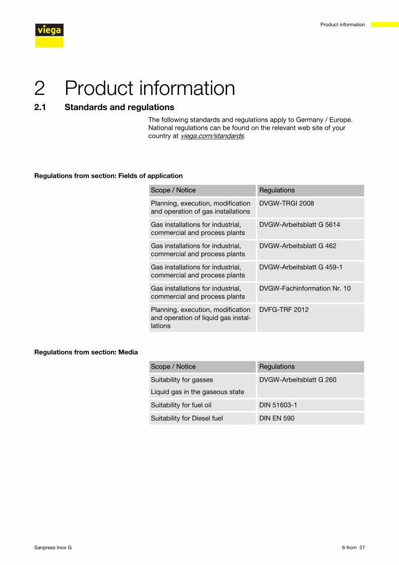
2 Product information2.1 Standards and regulations
The following standards and regulations apply to Germany / Europe.National regulations can be found on the relevant web site of yourcountry at viega.com/standards.
Scope / Notice Regulations
Planning, execution, modificationand operation of gas installations
DVGW-TRGI 2008
Gas installations for industrial,commercial and process plants
DVGW-Arbeitsblatt G 5614
Gas installations for industrial,commercial and process plants
DVGW-Arbeitsblatt G 462
Gas installations for industrial,commercial and process plants
DVGW-Arbeitsblatt G 459-1
Gas installations for industrial,commercial and process plants
DVGW-Fachinformation Nr. 10
Planning, execution, modificationand operation of liquid gas instal-lations
DVFG-TRF 2012
Scope / Notice Regulations
Suitability for gasses
Liquid gas in the gaseous state
DVGW-Arbeitsblatt G 260
Suitability for fuel oil DIN 51603-1
Suitability for Diesel fuel DIN EN 590
Regulations from section: Fields of application
Regulations from section: Media
Product information
Sanpress Inox G 6 from 27
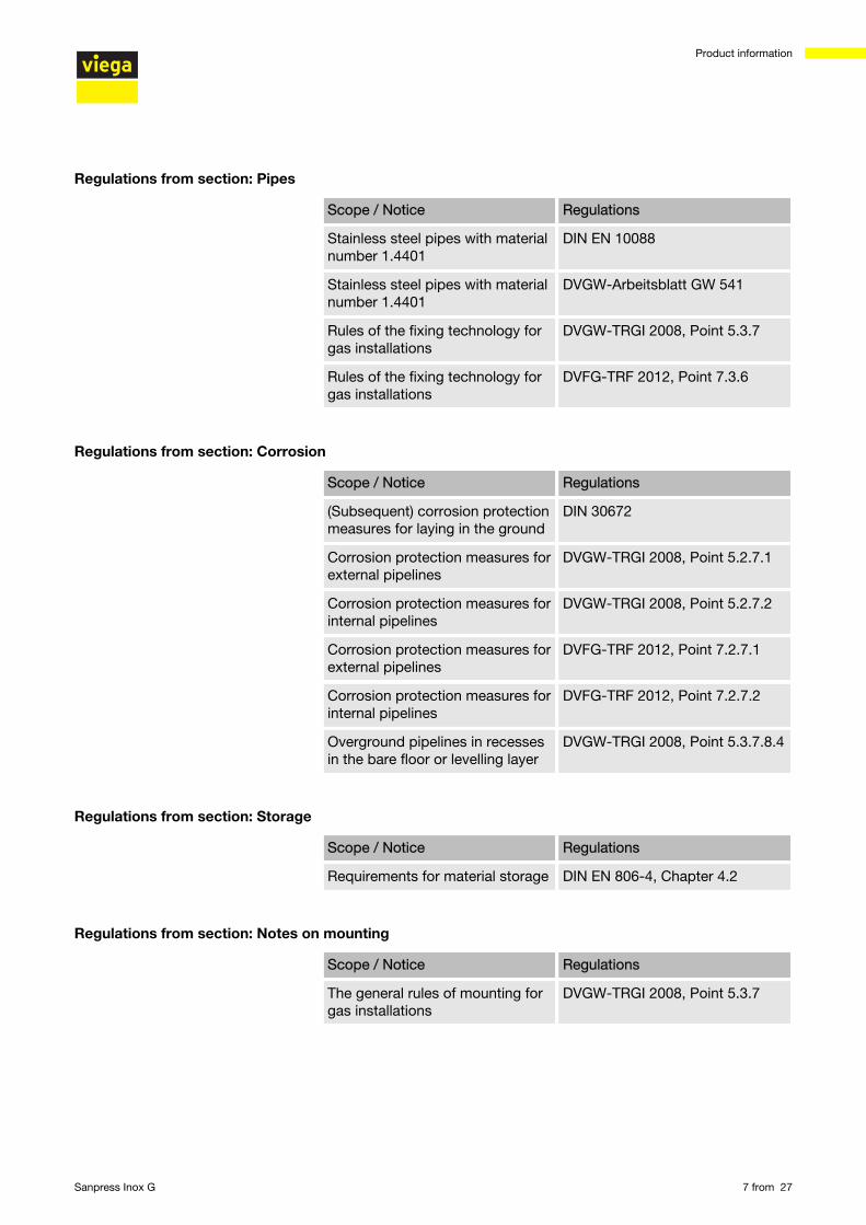
Scope / Notice Regulations
Stainless steel pipes with materialnumber 1.4401
DIN EN 10088
Stainless steel pipes with materialnumber 1.4401
DVGW-Arbeitsblatt GW 541
Rules of the fixing technology forgas installations
DVGW-TRGI 2008, Point 5.3.7
Rules of the fixing technology forgas installations
DVFG-TRF 2012, Point 7.3.6
Scope / Notice Regulations
(Subsequent) corrosion protectionmeasures for laying in the ground
DIN 30672
Corrosion protection measures forexternal pipelines
DVGW-TRGI 2008, Point 5.2.7.1
Corrosion protection measures forinternal pipelines
DVGW-TRGI 2008, Point 5.2.7.2
Corrosion protection measures forexternal pipelines
DVFG-TRF 2012, Point 7.2.7.1
Corrosion protection measures forinternal pipelines
DVFG-TRF 2012, Point 7.2.7.2
Overground pipelines in recessesin the bare floor or levelling layer
DVGW-TRGI 2008, Point 5.3.7.8.4
Scope / Notice Regulations
Requirements for material storage DIN EN 806-4, Chapter 4.2
Scope / Notice Regulations
The general rules of mounting forgas installations
DVGW-TRGI 2008, Point 5.3.7
Regulations from section: Pipes
Regulations from section: Corrosion
Regulations from section: Storage
Regulations from section: Notes on mounting
Product information
Sanpress Inox G 7 from 27
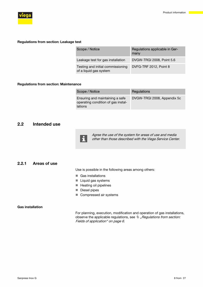
Scope / Notice Regulations applicable in Ger-many
Leakage test for gas installation DVGW-TRGI 2008, Point 5.6
Testing and initial commissioningof a liquid gas system
DVFG-TRF 2012, Point 8
Scope / Notice Regulations
Ensuring and maintaining a safeoperating condition of gas instal-lations
DVGW-TRGI 2008, Appendix 5c
2.2 Intended use
Agree the use of the system for areas of use and mediaother than those described with the Viega Service Center.
2.2.1 Areas of useUse is possible in the following areas among others:
n Gas installationsn Liquid gas systemsn Heating oil pipelinesn Diesel pipesn Compressed air systems
For planning, execution, modification and operation of gas installations,observe the applicable regulations, see Ä „Regulations from section:Fields of application“ on page 6.
Regulations from section: Leakage test
Regulations from section: Maintenance
Gas installation
Product information
Sanpress Inox G 8 from 27
Use is possible in the gas installations described below:
n Gas installations– low pressure range ≤ 100 hPa (100 mbar)– medium pressure range from 100 hPa (100 mbar) up to 0.1 MPa (1 bar)– industrial, commercial and process technical systems with the
corresponding directives and technical regulationsn Liquid gas systems
– with liquid gas tank in medium pressure range downstream ofthe pressure regulating valve, 1st level on theliquid gas tank > 100 hPa (100 mbar) up to a permitted operatingpressure of 0.5 MPa (5 bar)
– with liquid gas tank in the low pressure range≤ 100 hPa (100 mbar) behind the pressure regulating valve, 2ndlevel
– with liquid gas pressurised container (liquid gas bottles) < 16 kgbehind the small bottle pressure regulating valve
– with liquid gas tank (liquid gas bottle) ≥ 16 kgbehind the large bottle pressure regulating device
2.2.2 MediaThe system is suitable for the following media, amongst others:
For the applicable directives, see Ä „Regulations from section:Media“ on page 6.
n Gasesn Liquid gases, only in the gaseous state for domestic and commercial
applicationsn Fuel oiln Diesel fueln Compressed air
2.3 Product description2.3.1 Overview
The piping system consists of press connectors in connection withstainless steel pipes and the corresponding press tools.
Product information
Sanpress Inox G 9 from 27
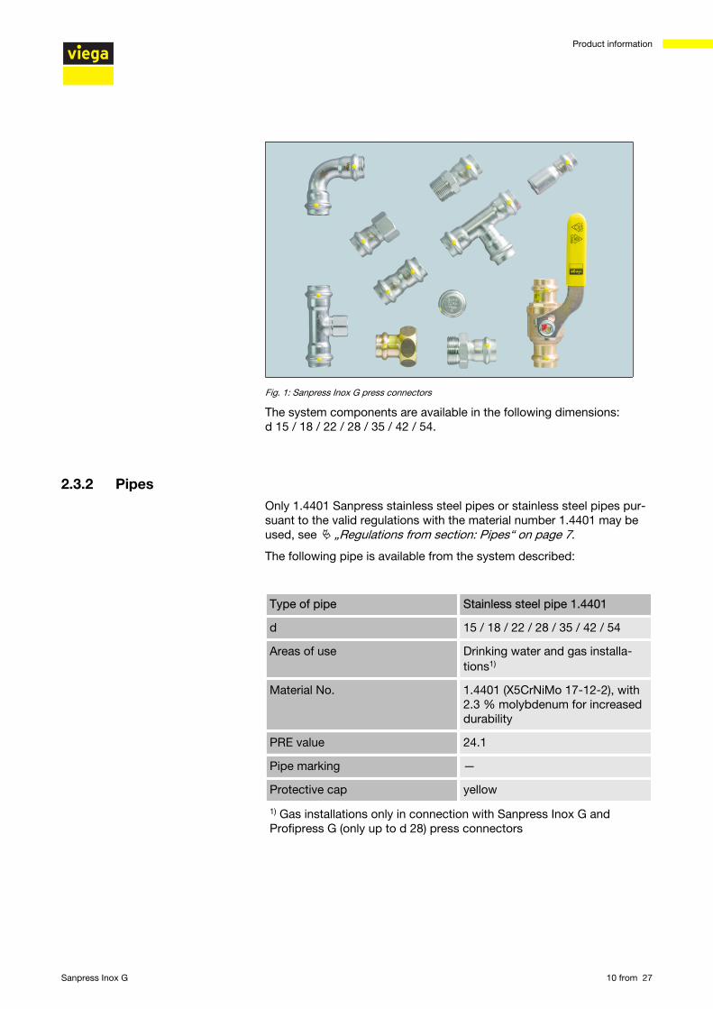
Fig. 1: Sanpress Inox G press connectors
The system components are available in the following dimensions:d 15 / 18 / 22 / 28 / 35 / 42 / 54.
2.3.2 PipesOnly 1.4401 Sanpress stainless steel pipes or stainless steel pipes pur-suant to the valid regulations with the material number 1.4401 may beused, see Ä „Regulations from section: Pipes“ on page 7.
The following pipe is available from the system described:
Type of pipe Stainless steel pipe 1.4401
d 15 / 18 / 22 / 28 / 35 / 42 / 54
Areas of use Drinking water and gas installa-tions1)
Material No. 1.4401 (X5CrNiMo 17-12-2), with2.3 % molybdenum for increaseddurability
PRE value 24.1
Pipe marking —
Protective cap yellow
1) Gas installations only in connection with Sanpress Inox G andProfipress G (only up to d 28) press connectors
Product information
Sanpress Inox G 10 from 27
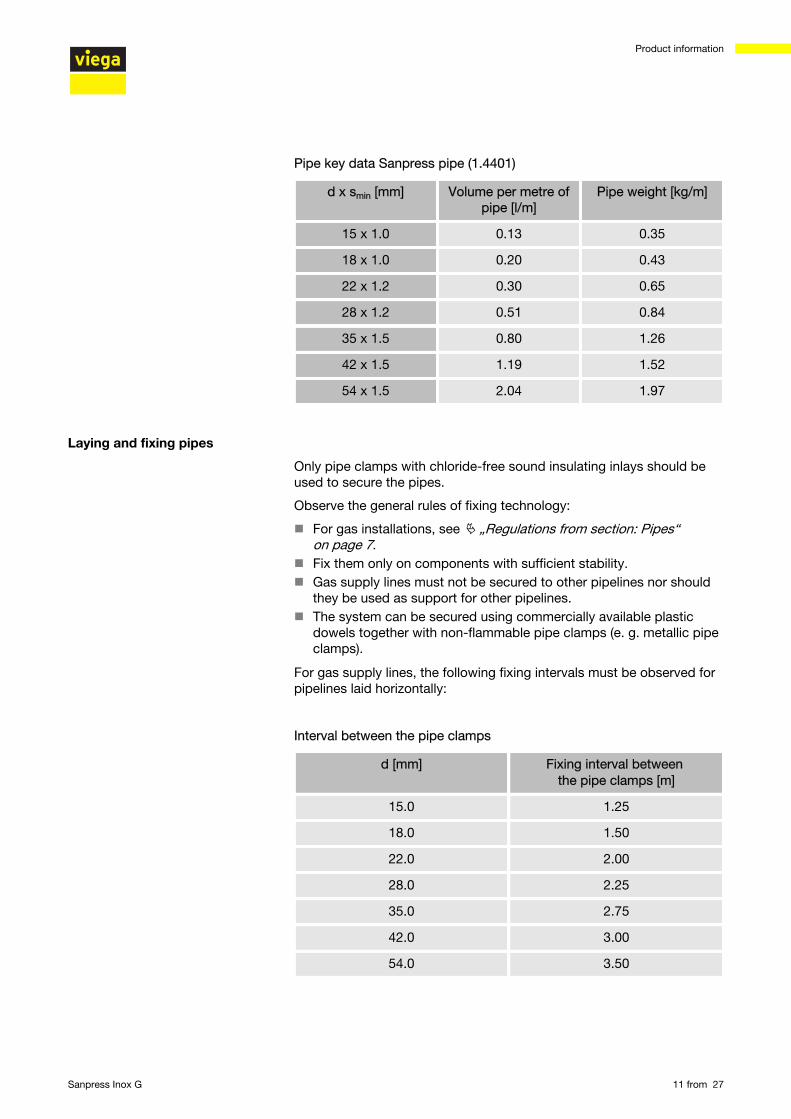
Pipe key data Sanpress pipe (1.4401)
d x smin [mm] Volume per metre ofpipe [l/m]
Pipe weight [kg/m]
15 x 1.0 0.13 0.35
18 x 1.0 0.20 0.43
22 x 1.2 0.30 0.65
28 x 1.2 0.51 0.84
35 x 1.5 0.80 1.26
42 x 1.5 1.19 1.52
54 x 1.5 2.04 1.97
Only pipe clamps with chloride-free sound insulating inlays should beused to secure the pipes.
Observe the general rules of fixing technology:
n For gas installations, see Ä „Regulations from section: Pipes“on page 7.
n Fix them only on components with sufficient stability.n Gas supply lines must not be secured to other pipelines nor should
they be used as support for other pipelines.n The system can be secured using commercially available plastic
dowels together with non-flammable pipe clamps (e. g. metallic pipeclamps).
For gas supply lines, the following fixing intervals must be observed forpipelines laid horizontally:
Interval between the pipe clamps
d [mm] Fixing interval between the pipe clamps [m]
15.0 1.25
18.0 1.50
22.0 2.00
28.0 2.25
35.0 2.75
42.0 3.00
54.0 3.50
Laying and fixing pipes
Product information
Sanpress Inox G 11 from 27
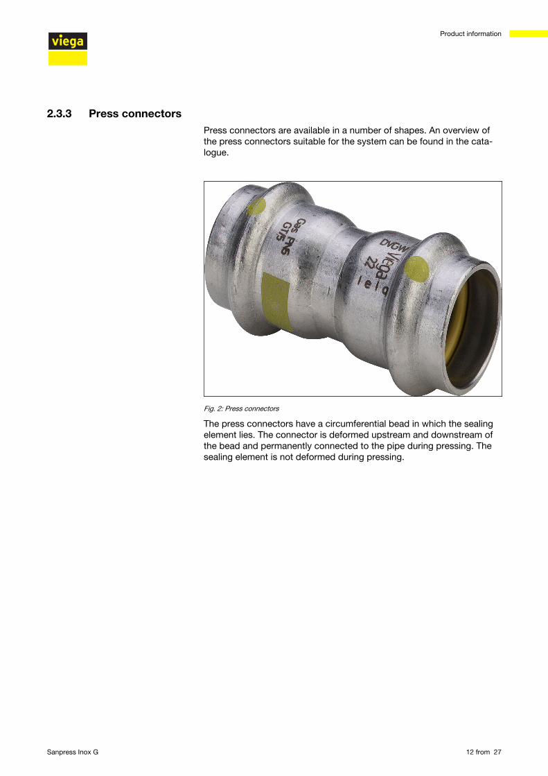
2.3.3 Press connectorsPress connectors are available in a number of shapes. An overview ofthe press connectors suitable for the system can be found in the cata-logue.
Fig. 2: Press connectors
The press connectors have a circumferential bead in which the sealingelement lies. The connector is deformed upstream and downstream ofthe bead and permanently connected to the pipe during pressing. Thesealing element is not deformed during pressing.
Product information
Sanpress Inox G 12 from 27
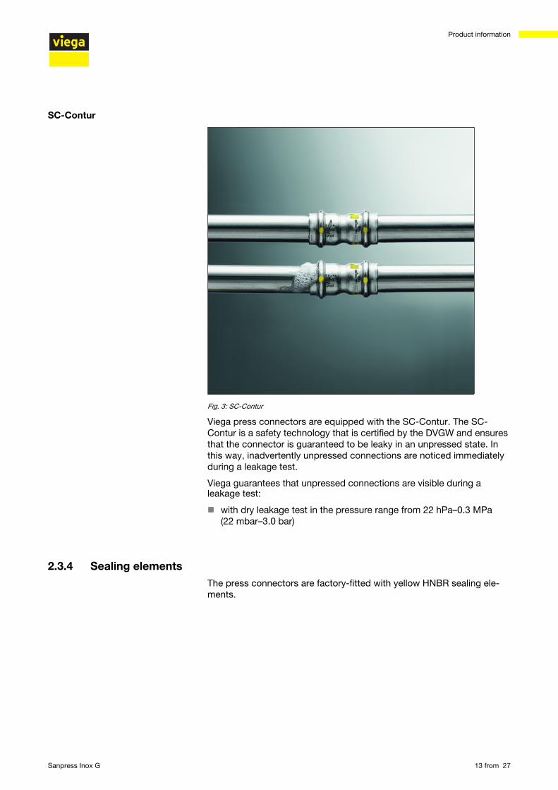
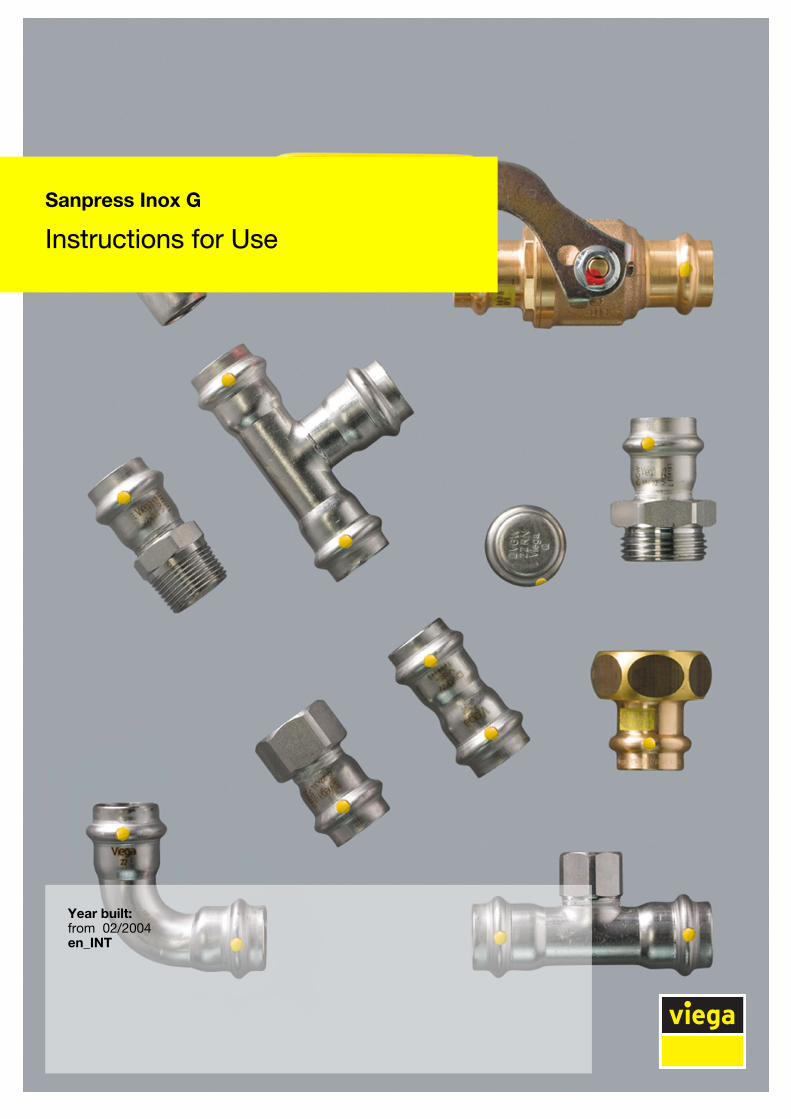
Fig. 3: SC-Contur
Viega press connectors are equipped with the SC-Contur. The SC-Contur is a safety technology that is certified by the DVGW and ensuresthat the connector is guaranteed to be leaky in an unpressed state. Inthis way, inadvertently unpressed connections are noticed immediatelyduring a leakage test.
Viega guarantees that unpressed connections are visible during aleakage test:
n with dry leakage test in the pressure range from 22 hPa–0.3 MPa(22 mbar–3.0 bar)
2.3.4 Sealing elementsThe press connectors are factory-fitted with yellow HNBR sealing ele-ments.
SC-Contur
Product information
Sanpress Inox G 13 from 27
Use Gas installation Liquid gas installation Heating oil and dieselpipelines
Operating temperature -20 °C up to +70 °C -20 °C up to +70 °C ≤ 40 °C
Operating pressure ≤ 0.5 MPa (5 bar)(MOP 5)
≤ 0.5 MPa (5 bar) (HTR /GT5)1)
≤ 0.5 MPa (5 bar)(MOP 5)
≤ 0.5 MPa (5 bar) (HTR /GT5)1)
≤ 0.5 MPa (5 bar)
1) Operating pressure at HTR requirement max. 0.5 MPa (5 bar) (GT5)
2.3.5 Markings on components
The pipe markings contain important information regarding the materialconfiguration and manufacture of the pipes. Their meaning is as follows:
n manufacturern system namen pipe materialn certificationn dimensionn supplier's markn date of manufacturen batch numbern CE markn DOP and DOP numbern manufacturing standard
The press connectors are marked with a coloured dot. This identifiesthe SC-Contur, where the test medium would escape in the case of aninadvertently unpressed connection.
Pipe marking
Markings on press connectors
Product information
Sanpress Inox G 14 from 27
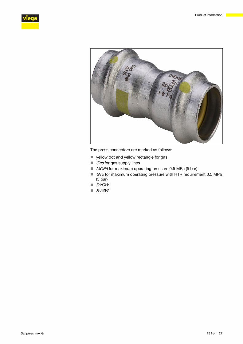
The press connectors are marked as follows:
n yellow dot and yellow rectangle for gasn Gas for gas supply linesn MOP5 for maximum operating pressure 0.5 MPa (5 bar)n GT5 for maximum operating pressure with HTR requirement 0.5 MPa
(5 bar)n DVGWn SVGW
Product information
Sanpress Inox G 15 from 27
2.4 Information for use2.4.1 Corrosion
Depending on the area of use, corrosion protection measures may haveto be taken into account. One differentiates between external pipelines(underground and overground external pipelines), as well as internalpipelines.
Information about the area of use, also see Ä Chapter 2.2.1 „Areas ofuse“ on page 8.
The pertinent guidelines must be observed for corrosion protection, seeÄ „Regulations from section: Corrosion“ on page 7.
Overground pipes and fittings in rooms do not normally require externalcorrosion protection.
There are exceptions in the following cases:
n There is external contact with materials containing chloride.n Stainless steel pipes must not come into contact with building mate-
rials or mortar containing chloride.n in aggressive surroundingsn In recesses within bare floors or in the compensating layer, they
must be treated in the same way as buried external pipelines, seeÄ „Regulations from section: Corrosion“ on page 7.
Product information
Sanpress Inox G 16 from 27
3 Handling3.1 Transport
Observe the following when transporting pipes:
n Do not pull the pipes over the sill. The surface could be damaged.n Secure pipes during transportation. Pipes may become bent due to
shifting.n Do not damage the protective caps on the pipe ends and do not
remove them until immediately before mounting. Damaged pipeends may not be pressed.
3.2 StorageFor storage, comply with the requirements specified in the applicableregulations, see Ä „Regulations from section: Storage“ on page 7:
n Store components in a clean and dry place.n Do not store the components directly on the floor.n Provide at least three points of support for the storage of pipes.n Where possible, store different sizes separately.
Store small sizes on top of larger sizes if separate storage is not pos-sible.
n Only use stainless steel cleaning agent to clean surfaces.n To prevent contact corrosion, store pipes of different materials sepa-
rately.
3.3 Assembly information3.3.1 Mounting instructions
System components may, in some cases, become damaged throughtransportation and storage.
n Check all parts.n Replace damaged components.n Do not repair damaged components.n Contaminated components may not be installed.
Checking system components
Handling
Sanpress Inox G 17 from 27
NOTICE! Active and possibly passive protection measures arerequired to protect a gas installation from tampering byunauthorised persons, see Ä „Regulations from section:Notes on mounting“ on page 7.
Active protective measures (e. g. gas flow monitor) mustalways be taken.
Passive protective measures (e.g. gas safety plugs andcaps) must be selected and employed depending on theinstallation.
The following conditions amongst others are valid when laying gassupply lines:
n Lay gas supply lines with clearance from the installation body, con-cealed without hollow spaces or in ventilated ducts or shafts.
n Do not install gas supply lines with operating pressures > 100 hPa(100 mbar) concealed in the wall.
n Arrange gas supply lines in such a way that condense water or waterdripping from other pipes and components does not affect them.
n Do not lay gas supply lines in screed.n Shut-off systems and detachable connections must be easily acces-
sible.
Requirements on concealed installations:
n Lay stress-free.n Apply corrosion protection.n Do not use any detachable connections (screw fittings).
Continuous, connection-free gas supply lines may be laid inhollow spaces (pre-wall constructions) to be connected to agas device or a gas socket.
Ventilation is not required.
The general rules of mounting for gas supply lines
Handling
Sanpress Inox G 18 from 27
3.3.2 Permitted exchange of sealing elements
Important instructionWith their material-specific qualities, sealing elements inpress connectors are adapted for use with the corre-sponding media and/or the areas of use of the piping sys-tems and are generally only certified for them.
The exchange of a sealing element is generally permitted.The sealing element must be replaced by a sealing elementof the same material Ä Chapter 2.3.4 „Sealing elements“on page 13. The use of other sealing elements is not per-mitted.
If the sealing element in the press connector is obviously damaged, itshould be exchanged for a Viega replacement sealing element made ofthe same material.
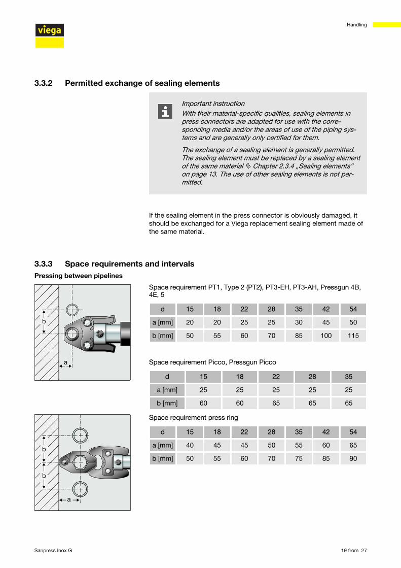
3.3.3 Space requirements and intervals
Space requirement PT1, Type 2 (PT2), PT3-EH, PT3-AH, Pressgun 4B,4E, 5
d 15 18 22 28 35 42 54
a [mm] 20 20 25 25 30 45 50
b [mm] 50 55 60 70 85 100 115
Space requirement Picco, Pressgun Picco
d 15 18 22 28 35
a [mm] 25 25 25 25 25
b [mm] 60 60 65 65 65
Space requirement press ring
d 15 18 22 28 35 42 54
a [mm] 40 45 45 50 55 60 65
b [mm] 50 55 60 70 75 85 90
Pressing between pipelines
Handling
Sanpress Inox G 19 from 27
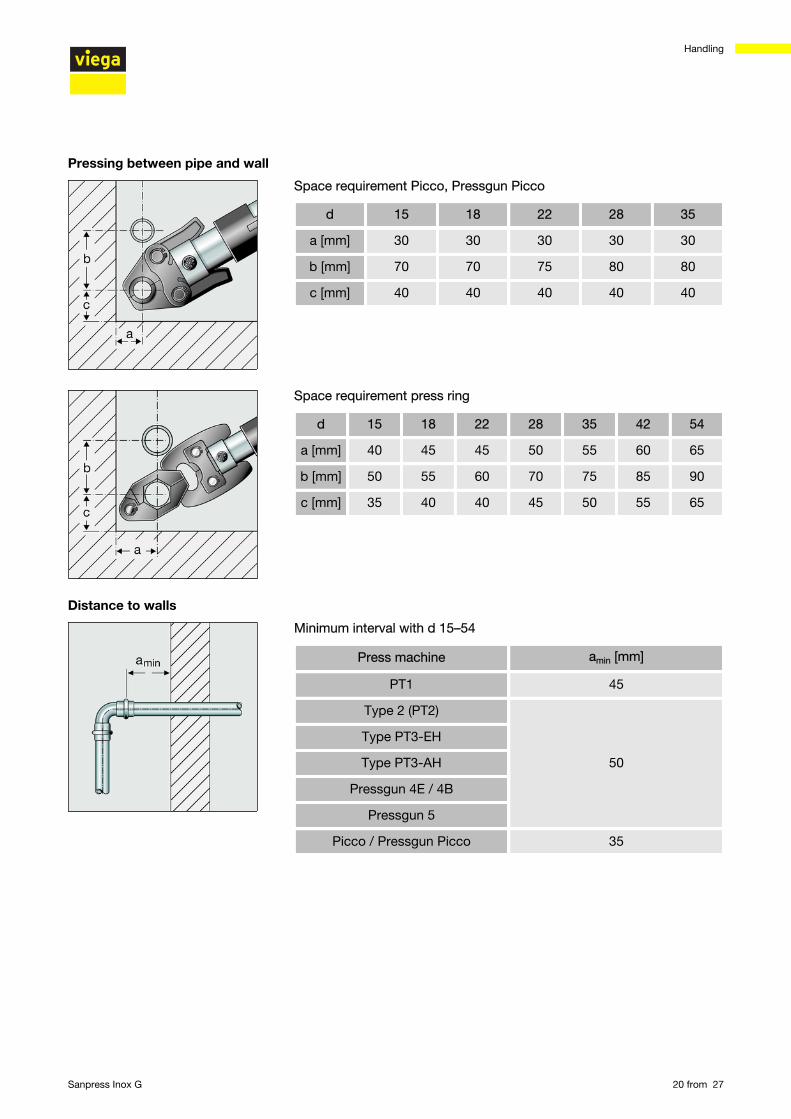
Space requirement Picco, Pressgun Picco
d 15 18 22 28 35
a [mm] 30 30 30 30 30
b [mm] 70 70 75 80 80
c [mm] 40 40 40 40 40
Space requirement press ring
d 15 18 22 28 35 42 54
a [mm] 40 45 45 50 55 60 65
b [mm] 50 55 60 70 75 85 90
c [mm] 35 40 40 45 50 55 65
Minimum interval with d 15–54
Press machine amin [mm]
PT1 45
Type 2 (PT2)
50
Type PT3-EH
Type PT3-AH
Pressgun 4E / 4B
Pressgun 5
Picco / Pressgun Picco 35
Pressing between pipe and wall
Distance to walls
Handling
Sanpress Inox G 20 from 27
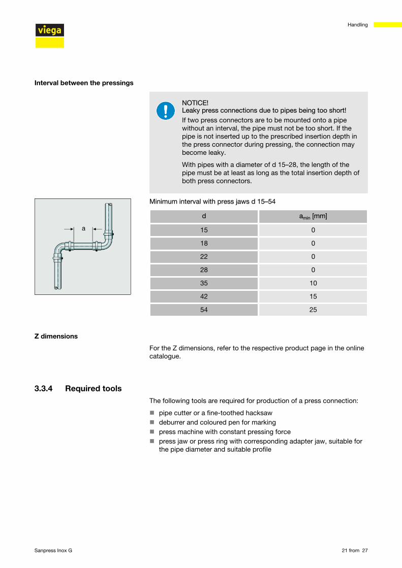
NOTICE! Leaky press connections due to pipes being too short!If two press connectors are to be mounted onto a pipewithout an interval, the pipe must not be too short. If thepipe is not inserted up to the prescribed insertion depth inthe press connector during pressing, the connection maybecome leaky.
With pipes with a diameter of d 15–28, the length of thepipe must be at least as long as the total insertion depth ofboth press connectors.
Minimum interval with press jaws d 15–54
d amin [mm]
15 0
18 0
22 0
28 0
35 10
42 15
54 25
For the Z dimensions, refer to the respective product page in the onlinecatalogue.
3.3.4 Required toolsThe following tools are required for production of a press connection:
n pipe cutter or a fine-toothed hacksawn deburrer and coloured pen for markingn press machine with constant pressing forcen press jaw or press ring with corresponding adapter jaw, suitable for
the pipe diameter and suitable profile
Interval between the pressings
Z dimensions
Handling
Sanpress Inox G 21 from 27
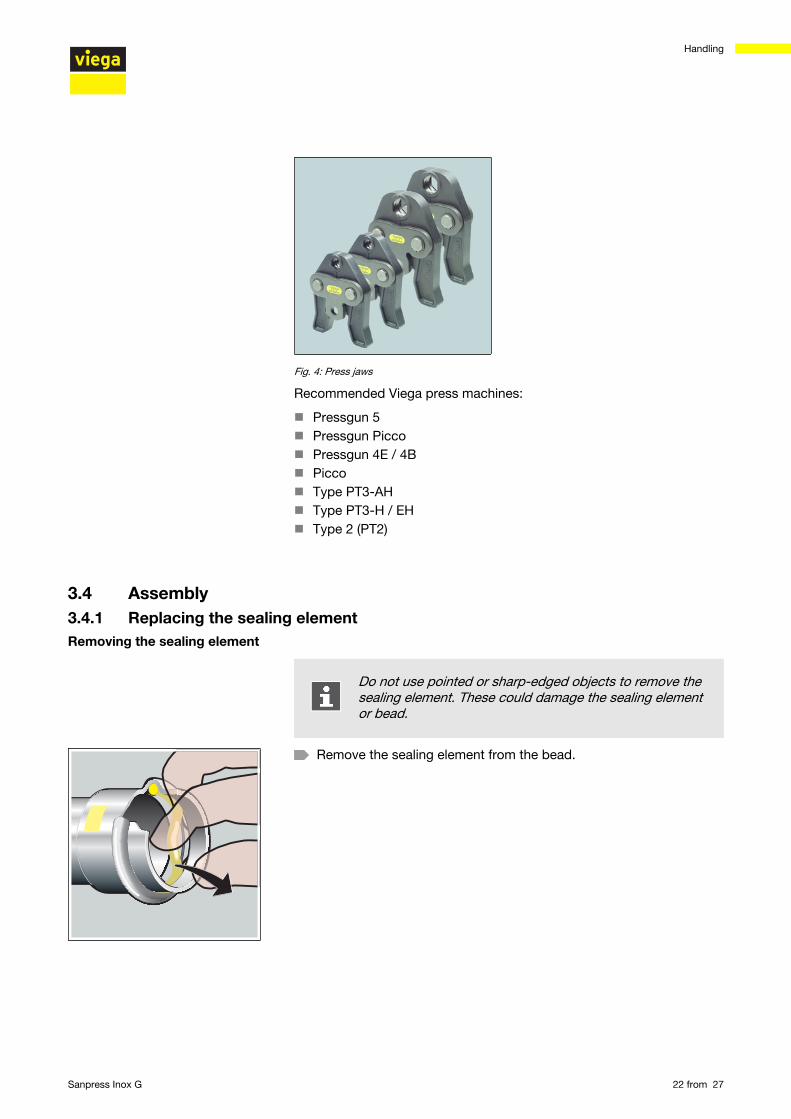
Fig. 4: Press jaws
Recommended Viega press machines:
n Pressgun 5n Pressgun Piccon Pressgun 4E / 4Bn Piccon Type PT3-AHn Type PT3-H / EHn Type 2 (PT2)
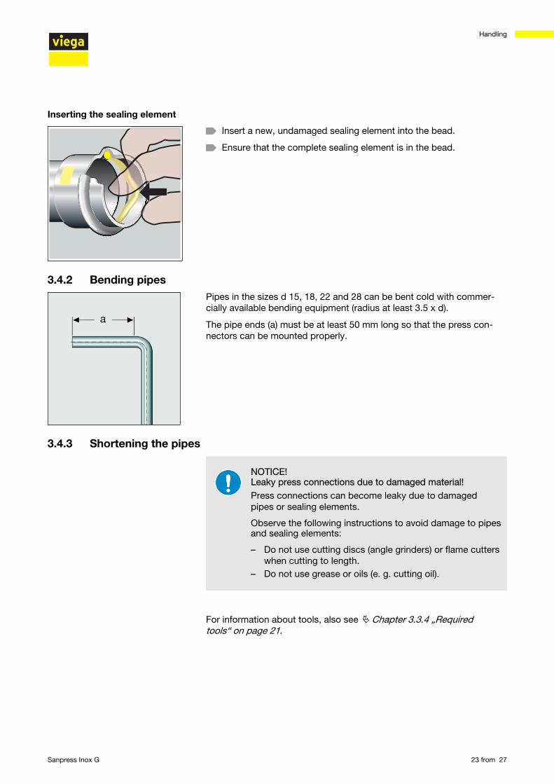
3.4 Assembly3.4.1 Replacing the sealing element
Do not use pointed or sharp-edged objects to remove thesealing element. These could damage the sealing elementor bead.
Remove the sealing element from the bead.
Removing the sealing element
Handling
Sanpress Inox G 22 from 27
Insert a new, undamaged sealing element into the bead.
Ensure that the complete sealing element is in the bead.
3.4.2 Bending pipesPipes in the sizes d 15, 18, 22 and 28 can be bent cold with commer-cially available bending equipment (radius at least 3.5 x d).
The pipe ends (a) must be at least 50 mm long so that the press con-nectors can be mounted properly.
3.4.3 Shortening the pipes
NOTICE! Leaky press connections due to damaged material!Press connections can become leaky due to damagedpipes or sealing elements.
Observe the following instructions to avoid damage to pipesand sealing elements:
– Do not use cutting discs (angle grinders) or flame cutterswhen cutting to length.
– Do not use grease or oils (e. g. cutting oil).
For information about tools, also see Ä Chapter 3.3.4 „Requiredtools“ on page 21.
Inserting the sealing element
Handling
Sanpress Inox G 23 from 27
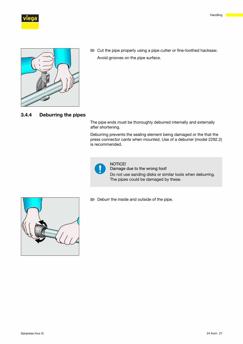
Cut the pipe properly using a pipe cutter or fine-toothed hacksaw.
Avoid grooves on the pipe surface.
3.4.4 Deburring the pipesThe pipe ends must be thoroughly deburred internally and externallyafter shortening.
Deburring prevents the sealing element being damaged or the that thepress connector cants when mounted. Use of a deburrer (model 2292.2)is recommended.
NOTICE! Damage due to the wrong tool!Do not use sanding disks or similar tools when deburring.The pipes could be damaged by these.
Deburr the inside and outside of the pipe.
Handling
Sanpress Inox G 24 from 27
3.4.5 Pressing the connection
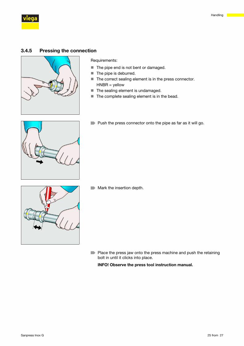
Requirements:
n The pipe end is not bent or damaged.n The pipe is deburred.n The correct sealing element is in the press connector.
HNBR = yellown The sealing element is undamaged.n The complete sealing element is in the bead.
Push the press connector onto the pipe as far as it will go.
Mark the insertion depth.
Place the press jaw onto the press machine and push the retainingbolt in until it clicks into place.
INFO! Observe the press tool instruction manual.
Handling
Sanpress Inox G 25 from 27
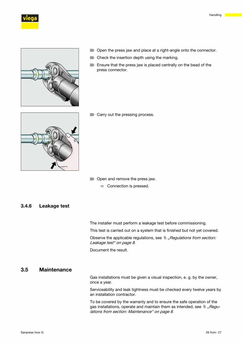
Open the press jaw and place at a right-angle onto the connector.
Check the insertion depth using the marking.
Ensure that the press jaw is placed centrally on the bead of thepress connector.
Carry out the pressing process.
Open and remove the press jaw.
ð Connection is pressed.
3.4.6 Leakage test
The installer must perform a leakage test before commissioning.
This test is carried out on a system that is finished but not yet covered.
Observe the applicable regulations, see Ä „Regulations from section:Leakage test“ on page 8.
Document the result.
3.5 MaintenanceGas installations must be given a visual inspection, e. g. by the owner,once a year.
Serviceability and leak tightness must be checked every twelve years byan installation contractor.
To be covered by the warranty and to ensure the safe operation of thegas installations, operate and maintain them as intended, see Ä „Regu-lations from section: Maintenance“ on page 8.
Handling
Sanpress Inox G 26 from 27
3.6 DisposalSeparate the product and packaging materials (e. g. paper, metal,plastic or non-ferrous metals) and dispose of in accordance with validnational legal requirements.
Handling
Sanpress Inox G 27 from 27