Embed Size (px)
Citation preview
FPS-80, FPS-150, and FPS-210Instructions
• Digital, Touchscreen, or Mechanical timer• Featuring Separ Filter fuel water separator• Shutdown and visual / audio alarms
Fuel Polishing System Contact Us
Reverso Pumps, Inc4001 SW 47th Ave, Suite 201Davie, FL 33314Ph: (954) [email protected]
2 Reverso Pumps, Inc.
Table of ContentsSystem Overview.............................................................................................................................. 3Electrical and Piping Installation ....................................................................................................... 4Control Panel with Digital Timer: Overview, Alarms, Reset .............................................................. 5Digital Control ................................................................................................................................... 6Touchscreen Control: Program Setup .............................................................................................. 7Touchscreen Control: Alarm Status .................................................................................................. 8Touchscreen Control: System Time Setup and System Log ............................................................ 9Touchscreen Control: System Overview......................................................................................... 10Touchscreen Control: Maintenance ................................................................................................ 11Mechanical Control ......................................................................................................................... 12Filter Maintenance .......................................................................................................................... 13FPS-80 Technical Specifications .................................................................................................... 14FPS-80 Dimensions........................................................................................................................ 15FPS-150 Technical Specifications .................................................................................................. 16FPS-150 Dimensions...................................................................................................................... 17FPS-210 Technical Specifications .................................................................................................. 18FPS-210 Dimensions...................................................................................................................... 19Troubleshooting .............................................................................................................................. 20
The information herein is the property of Reverso Pumps, Inc. Without written permission, any copying, transmitting to others, and other use except for which it is loaned is prohibited.
3Reverso Pumps, Inc.
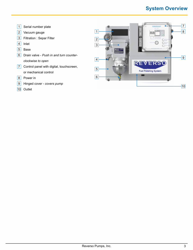
System Overview
Serial number plate
Vacuum gauge
Filtration : Separ Filter
Inlet
Base
Drain valve - Push in and turn counter-
clockwise to open
Control panel with digital, touchscreen,
or mechanical control
Power in
Hinged cover - covers pump
Outlet
8
10
9
7
3
6
5
4
1
2
1
5
3
7
8
9
10
2
6
4
4 Reverso Pumps, Inc.
Primary Inspection• Upon delivery inspect the Fuel Polishing System
(FPS) for any damage that may have occurred during shipment.
• Inspect the interior of the unit for mechanical or electrical damage.
• If the unit is damaged upon delivery, contact the shipping company immediately.
Mounting• The FPS should be wall mounted on a hard, vertical
surface capable of supporting the weight of the unit (using the bushing).
• A unit without an enclosure should be located under shelter, out of the weather if possible. The unit with the optional enclosure can be located in any location accessible to the operator.
• In all cases the unit should be located as close as possible to the tank being serviced. (refer to Max. Lift in Technical Specifications).
• When installing the unit below the level of the fuel on above ground fuel tanks, consideration should be made to the installation of an anti-siphon valve to prevent fuel spillage in the case of a leak in the piping system.
Electrical• Installation of unit should only be performed by
qualified installation personnel who have thoroughly read and understand the installation instructions covered in this manual.
• To avoid the risk of electric shock, make sure that the power supply is disconnected. Ensure that the power supply is at zero volts with a multimeter before making any electrical connections.
• To ensure operator safety the system must be connected to properly grounded power sources.
• Make sure that your unit and power supply are configured for the same voltage rating.
• Dry contacts are for external use.• External control voltage must be supplied by
customer.
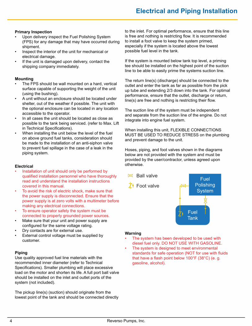
PipingUse quality approved fuel line materials with the recommended inner diameter (refer to Technical Specifications). Smaller plumbing will place excessive load on the motor and shorten its life. A full port ball valve should be installed on the inlet and outlet ports of the system (not included).
The pickup line(s) (suction) should originate from the lowest point of the tank and should be connected directly
to the inlet. For optimal performance, ensure that this line is free and nothing is restricting flow. It is recommended to install a foot valve to keep the system primed, especially if the system is located above the lowest possible fuel level in the tank.
If the system is mounted below tank top level, a priming tee should be installed on the highest point of the suction line to be able to easily prime the systems suction line.
The return line(s) (discharge) should be connected to the outlet and enter the tank as far as possible from the pick up tube and extending 2/3 down into the tank. For optimal performance, ensure that the outlet, discharge or return, line(s) are free and nothing is restricting their flow.
The suction line of the system must be independent and separate from the suction line of the engine. Do not integrate into engine fuel system.
When installing this unit, FLEXIBLE CONNECTIONS MUST BE USED TO REDUCE STRESS on the plumbing and prevent damage to the unit.
Hoses, piping, and foot valves shown in the diagrams below are not provided with the system and must be provided by the user/contractor, unless agreed upon otherwise.
Electrical and Piping Installation
FuelPolishing System
Fuel Tank Foot valve
Ball valve
FuelPolishing System
Fuel Tank Foot valve
Ball valve
Warning• The system has been developed to be used with
diesel fuel only. DO NOT USE WITH GASOLINE. • The system is designed to meet environmental
standards for safe operation (NOT for use with fluids that have a flash point below 100°F (38°C) (e. g. gasoline, alcohol).
5Reverso Pumps, Inc.
Control Panel with Digital Timer: Overview, Alarms, Reset
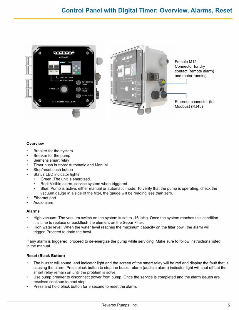
• Breaker for the system• Breaker for the pump• Siemens smart relay• Timer push buttons: Automatic and Manual• Stop/reset push button• Status LED indicator lights:
• Green: The unit is energized.• Red: Visible alarm, service system when triggered.• Blue: Pump is active, either manual or automatic mode. To verify that the pump is operating, check the
vacuum gauge in a side of the filter, the gauge will be reading less than zero. • Ethernet port• Audio alarm
• High vacuum: The vacuum switch on the system is set to -16 inHg. Once the system reaches this condition it is time to replace or backflush the element on the Separ Filter.
• High water level: When the water level reaches the maximum capacity on the filter bowl, the alarm will trigger. Proceed to drain the bowl.
If any alarm is triggered, proceed to de-energize the pump while servicing. Make sure to follow instructions listed in the manual.
• The buzzer will sound, and indicator light and the screen of the smart relay will be red and display the fault that is causing the alarm. Press black button to stop the buzzer alarm (audible alarm) indicator light will shut off but the smart relay remain on until the problem is solve.
• Use pump breaker to disconnect power from pump. Once the service is completed and the alarm issues are resolved continue to next step.
• Press and hold black button for 3 second to reset the alarm.
Overview
Alarms
Reset (Black Button)
Ethernet connector (for Modbus) (RJ45)
Female M12 Connector for dry contact (remote alarm) and motor running
6 Reverso Pumps, Inc.
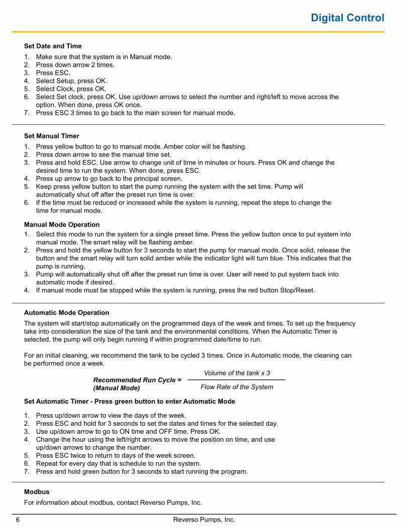
1. Make sure that the system is in Manual mode.2. Press down arrow 2 times.3. Press ESC.4. Select Setup, press OK. 5. Select Clock, press OK. 6. Select Set clock, press OK. Use up/down arrows to select the number and right/left to move across the
option. When done, press OK once.7. Press ESC 3 times to go back to the main screen for manual mode.
Digital Control
Set Date and Time
1. Select this mode to run the system for a single preset time. Press the yellow button once to put system into manual mode. The smart relay will be flashing amber.
2. Press and hold the yellow button for 3 seconds to start the pump for manual mode. Once solid, release the button and the smart relay will turn solid amber while the indicator light will turn blue. This indicates that the pump is running.
3. Pump will automatically shut off after the preset run time is over. User will need to put system back into automatic mode if desired.
4. If manual mode must be stopped while the system is running, press the red button Stop/Reset.
Manual Mode Operation
1. Press yellow button to go to manual mode. Amber color will be flashing.2. Press down arrow to see the manual time set.3. Press and hold ESC. Use arrow to change unit of time in minutes or hours. Press OK and change the
desired time to run the system. When done, press ESC.4. Press up arrow to go back to the principal screen.5. Keep press yellow button to start the pump running the system with the set time. Pump will
automatically shut off after the preset run time is over.6. If the time must be reduced or increased while the system is running, repeat the steps to change the
time for manual mode.
Set Manual Timer
Automatic Mode Operation
Modbus
Set Automatic Timer - Press green button to enter Automatic Mode
The system will start/stop automatically on the programmed days of the week and times. To set up the frequency take into consideration the size of the tank and the environmental conditions. When the Automatic Timer is selected, the pump will only begin running if within programmed date/time to run.
For an initial cleaning, we recommend the tank to be cycled 3 times. Once in Automatic mode, the cleaning can be performed once a week.
For information about modbus, contact Reverso Pumps, Inc.
Recommended Run Cycle = (Manual Mode)
Volume of the tank x 3
Flow Rate of the System
1. Press up/down arrow to view the days of the week.2. Press ESC and hold for 3 seconds to set the dates and times for the selected day.3. Use up/down arrow to go to ON time and OFF time. Press OK. 4. Change the hour using the left/right arrows to move the position on time, and use
up/down arrows to change the number.5. Press ESC twice to return to days of the week screen.6. Repeat for every day that is schedule to run the system.7. Press and hold green button for 3 seconds to start running the program.
7Reverso Pumps, Inc.
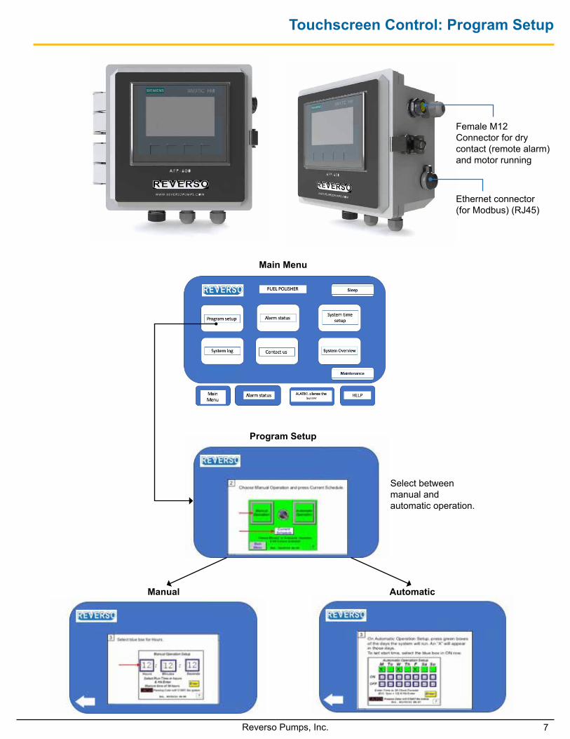
Touchscreen Control: Program Setup
Select between manual and automatic operation.
Manual
Main Menu
Program Setup
Automatic
Ethernet connector (for Modbus) (RJ45)
Female M12 Connector for dry contact (remote alarm) and motor running
8 Reverso Pumps, Inc.
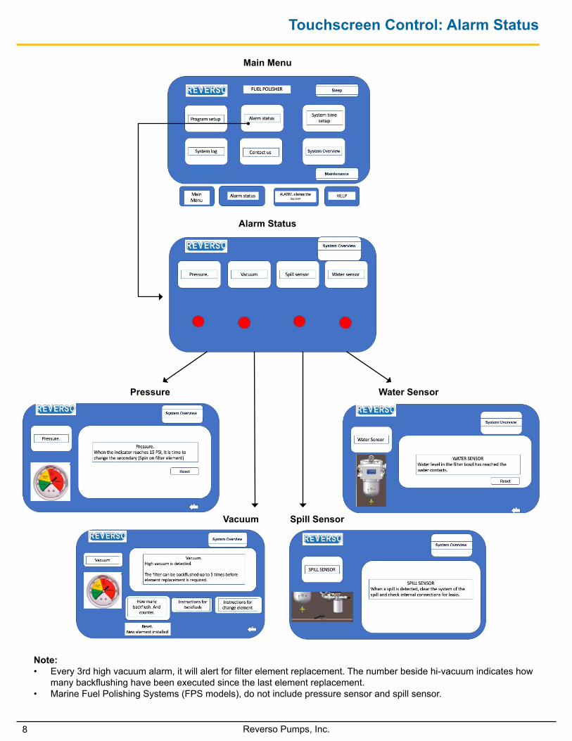
Touchscreen Control: Alarm Status
Main Menu
Alarm Status
Pressure Water Sensor
Vacuum Spill Sensor
Note: • Every 3rd high vacuum alarm, it will alert for filter element replacement. The number beside hi-vacuum indicates how
many backflushing have been executed since the last element replacement.• Marine Fuel Polishing Systems (FPS models), do not include pressure sensor and spill sensor.
9Reverso Pumps, Inc.
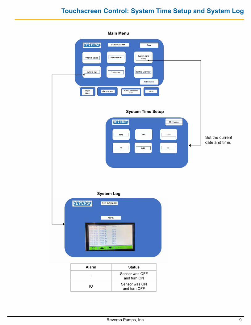
Touchscreen Control: System Time Setup and System Log
Set the current date and time.
Main Menu
System Time Setup
System Log
Alarm Status
I Sensor was OFF and turn ON
IO Sensor was ON and turn OFF
10 Reverso Pumps, Inc.
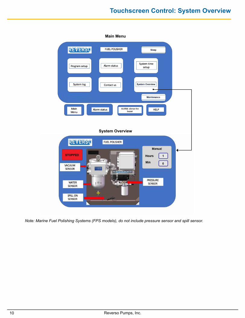
Touchscreen Control: System Overview
Main Menu
System Overview
Note: Marine Fuel Polishing Systems (FPS models), do not include pressure sensor and spill sensor.
11Reverso Pumps, Inc.
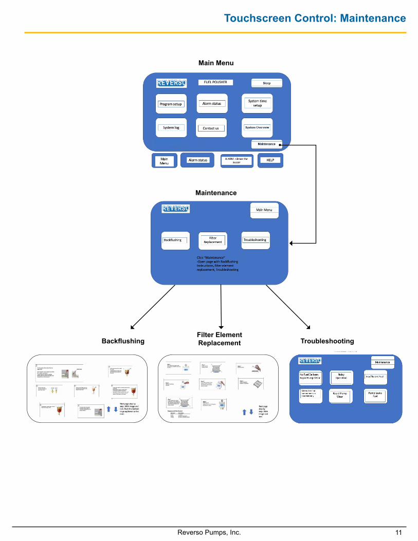
Touchscreen Control: Maintenance
BackflushingFilter ElementReplacement
Main Menu
Maintenance
Troubleshooting
12 Reverso Pumps, Inc.
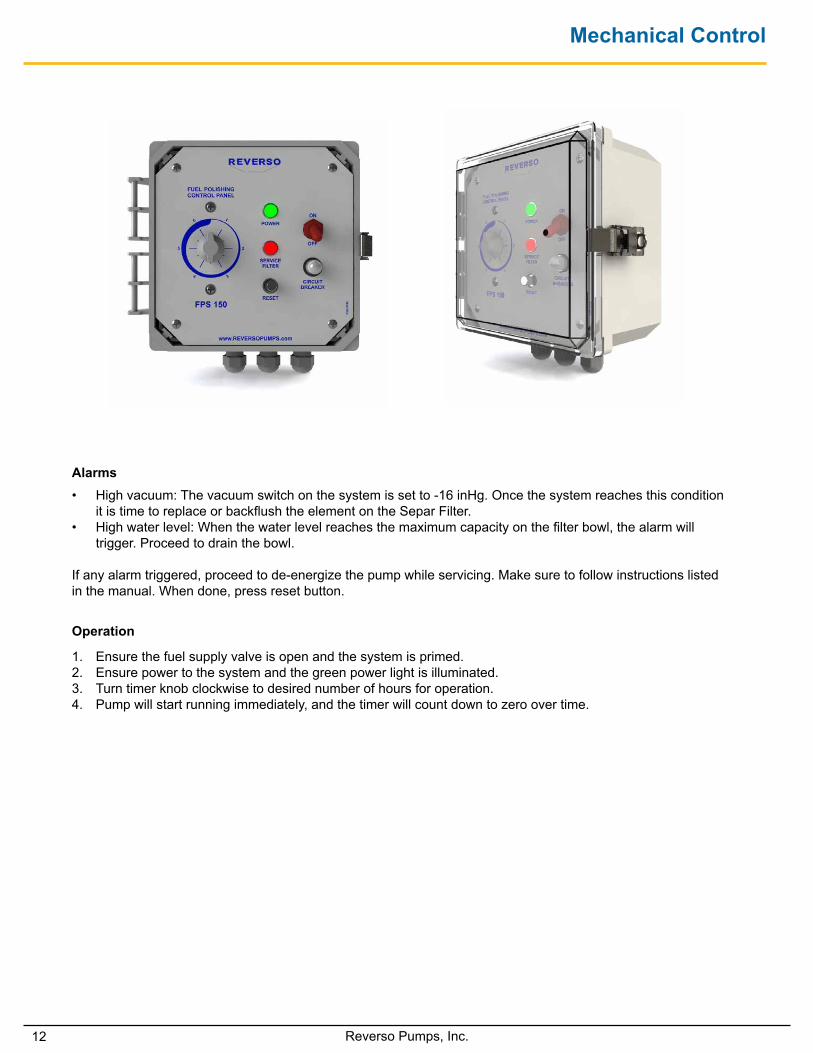
Mechanical Control
• High vacuum: The vacuum switch on the system is set to -16 inHg. Once the system reaches this condition it is time to replace or backflush the element on the Separ Filter.
• High water level: When the water level reaches the maximum capacity on the filter bowl, the alarm will trigger. Proceed to drain the bowl.
If any alarm triggered, proceed to de-energize the pump while servicing. Make sure to follow instructions listed in the manual. When done, press reset button.
Alarms
1. Ensure the fuel supply valve is open and the system is primed.2. Ensure power to the system and the green power light is illuminated.3. Turn timer knob clockwise to desired number of hours for operation. 4. Pump will start running immediately, and the timer will count down to zero over time.
Operation
13Reverso Pumps, Inc.
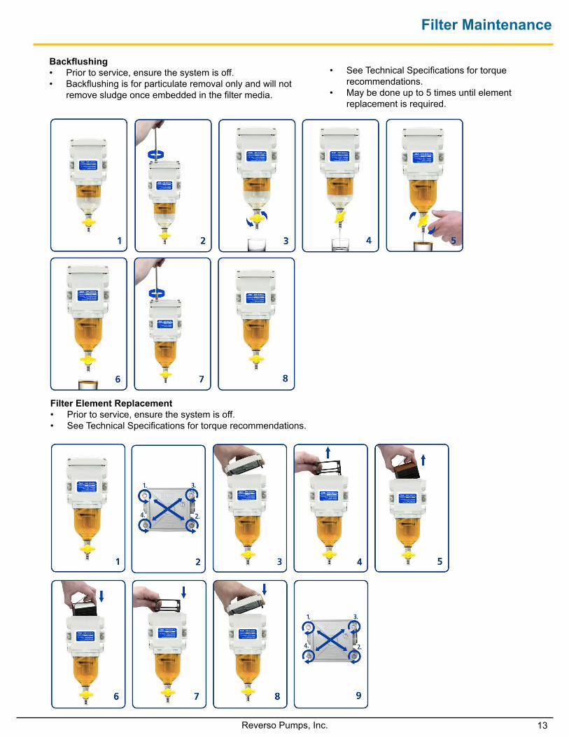
Filter Maintenance
Backflushing• Prior to service, ensure the system is off.• Backflushing is for particulate removal only and will not
remove sludge once embedded in the filter media.
Filter Element Replacement• Prior to service, ensure the system is off.• See Technical Specifications for torque recommendations.
• See Technical Specifications for torque recommendations.
• May be done up to 5 times until element replacement is required.
14 Reverso Pumps, Inc.
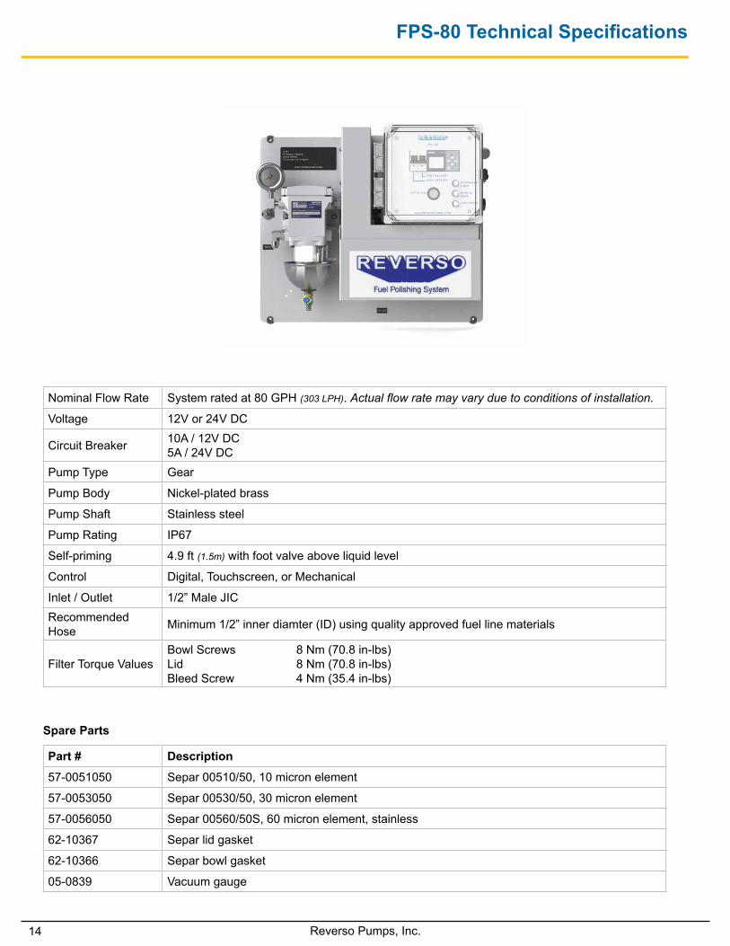
FPS-80 Technical Specifications
Nominal Flow Rate System rated at 80 GPH (303 LPH). Actual flow rate may vary due to conditions of installation.
Voltage 12V or 24V DC
Circuit Breaker 10A / 12V DC 5A / 24V DC
Pump Type Gear
Pump Body Nickel-plated brass
Pump Shaft Stainless steel
Pump Rating IP67
Self-priming 4.9 ft (1.5m) with foot valve above liquid level
Control Digital, Touchscreen, or Mechanical
Inlet / Outlet 1/2” Male JICRecommended Hose Minimum 1/2” inner diamter (ID) using quality approved fuel line materials
Filter Torque ValuesBowl Screws 8 Nm (70.8 in-lbs)Lid 8 Nm (70.8 in-lbs)Bleed Screw 4 Nm (35.4 in-lbs)
Spare Parts
Part # Description
57-0051050 Separ 00510/50, 10 micron element
57-0053050 Separ 00530/50, 30 micron element
57-0056050 Separ 00560/50S, 60 micron element, stainless
62-10367 Separ lid gasket
62-10366 Separ bowl gasket
05-0839 Vacuum gauge
15Reverso Pumps, Inc.
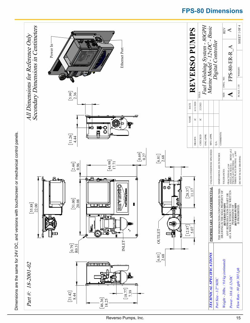
FPS-80 Dimensions
51
.00
20.0
8
44
.98
17.7
1
2.
440.
96 0.
690.
27
0.79
R0.
31
INLE
T
11
.26
4.44
5.99
2.36
46
.36
18.2
5
18
.77
7.39
21
.42
8.44
55
.88
22.0
0
Pow
er In
Ethe
rnet
Por
t
28
.37
11.1
7
12
.87
5.07
6.
812.
68
6.
812.
68
OU
TLET
Fuel
Pol
ishin
g Sy
stem
- 80
GPH
M
arin
e M
odel
- 12
vDC
- Bas
ic
Dig
ital C
ontro
ller
A
DO
NO
T SC
ALE
DR
AW
ING
FPS-
80-E
R-R_
ASH
EET
1 O
F 4
2/2/
2021
JC
UN
LESS
OTH
ERW
ISE
SPEC
IFIE
D:
SCA
LE: 1
:10
WEI
GH
T:
REV
DW
G.
NO
.
ASIZE
TITL
E:REV
ERSO
PU
MPS
NA
ME
DA
TE
COM
MEN
TS:
Q.A
.
MFG
APP
R.
ENG
APP
R.
CHEC
KED
DR
AW
N
DIM
ENSI
ON
S A
RE IN
INCH
ES
TOLE
RAN
CES:
FRA
CTIO
NA
L1/
64A
NG
ULA
R: M
AC
H
BEN
D
0.2
TWO
PLA
CE
DEC
IMA
L
.01
THRE
E PL
ACE
DEC
IMA
L
.005
PRO
PRIE
TAR
Y A
ND
CO
NFI
DEN
TIA
L
THE
INFO
RMA
TIO
N C
ON
TAIN
ED IN
TH
ISD
RAW
ING
IS T
HE
SOLE
PRO
PERT
Y O
FR
EVER
SO P
UM
PS
AN
Y R
EPR
OD
UC
TIO
N IN
PA
RT
OR
A
S A
WH
OLE
WIT
HO
UT
THE
WR
ITTE
N
PERM
ISSI
ON
OF
REV
ERSO
PU
MPS
IS
PRO
HIB
ITED
.
Part
#: 1
8-20
01-0
2A
ll D
imen
sions
for R
efer
ence
Onl
ySe
cond
ary
Dim
ensio
ns in
Cen
timet
ers
TEC
HN
ICA
L SP
ECIF
ICA
TIO
NS
Port
Size
- 1/
2" M
JIC
Wei
ght -
20l
bs. /
9.0
kg
(esti
mat
ed)
Pow
er -
10A
@ 1
2vD
C
Flow
Rat
e - 8
0 gp
h/ 3
03 L
ph
JC
6/11
/202
0
Dim
ensi
ons
are
the
sam
e fo
r 24V
DC
, and
ver
sion
s w
ith to
uchs
cree
n or
mec
hani
cal c
ontro
l pan
els.
16 Reverso Pumps, Inc.
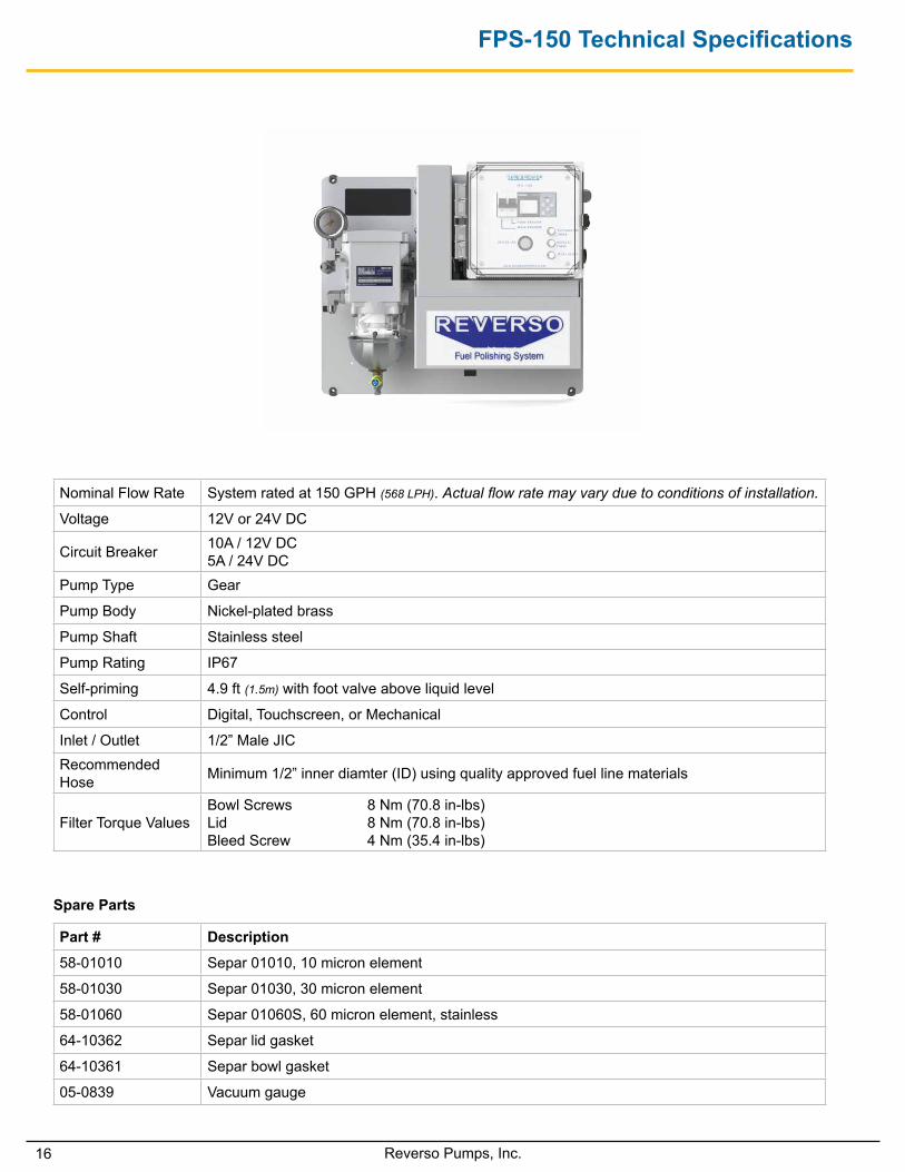
FPS-150 Technical Specifications
Nominal Flow Rate System rated at 150 GPH (568 LPH). Actual flow rate may vary due to conditions of installation.
Voltage 12V or 24V DC
Circuit Breaker 10A / 12V DC 5A / 24V DC
Pump Type Gear
Pump Body Nickel-plated brass
Pump Shaft Stainless steel
Pump Rating IP67
Self-priming 4.9 ft (1.5m) with foot valve above liquid level
Control Digital, Touchscreen, or Mechanical
Inlet / Outlet 1/2” Male JICRecommended Hose Minimum 1/2” inner diamter (ID) using quality approved fuel line materials
Filter Torque ValuesBowl Screws 8 Nm (70.8 in-lbs)Lid 8 Nm (70.8 in-lbs)Bleed Screw 4 Nm (35.4 in-lbs)
Spare Parts
Part # Description
58-01010 Separ 01010, 10 micron element
58-01030 Separ 01030, 30 micron element
58-01060 Separ 01060S, 60 micron element, stainless
64-10362 Separ lid gasket
64-10361 Separ bowl gasket
05-0839 Vacuum gauge
17Reverso Pumps, Inc.
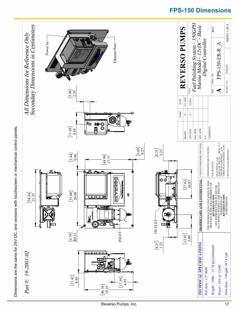
FPS-150 Dimensions
44
.98
17.7
1
0.
690.
27
51
.00
20.0
8
2.
440.
96
0.79
R0.
31
INLE
T
11
.26
4.44
5.98
2.35
46
.36
18.2
5
21
.42
8.44
17
.59
6.93
54
.24
21.3
5
Pow
er In
Ethe
rnet
Por
t
27
.62
10.8
7
8.
213.
23
12
.92
5.09
8.
213.
23
OU
TLET
Fuel
Pol
ishin
g Sy
stem
- 15
0GPH
M
arin
e M
odel
- 12
vDC
- Bas
ic
Dig
ital C
ontro
ller
DO
NO
T SC
ALE
DR
AW
ING
FPS-
150-
ER-R
_ASH
EET
1 O
F 4
2/2/
2021
JC
UN
LESS
OTH
ERW
ISE
SPEC
IFIE
D:
SCA
LE: 1
:10
WEI
GH
T:
REV
DW
G.
NO
.
ASIZE
TITL
E:REV
ERSO
PU
MPS
NA
ME
DA
TE
COM
MEN
TS:
Q.A
.
MFG
APP
R.
ENG
APP
R.
CHEC
KED
DR
AW
N
DIM
ENSI
ON
S A
RE IN
INCH
ES
TOLE
RAN
CES:
FRA
CTIO
NA
L1/
64A
NG
ULA
R: M
AC
H
BEN
D
0.2
TWO
PLA
CE
DEC
IMA
L
.01
THRE
E PL
ACE
DEC
IMA
L
.005
PRO
PRIE
TAR
Y A
ND
CO
NFI
DEN
TIA
L
THE
INFO
RMA
TIO
N C
ON
TAIN
ED IN
TH
ISD
RAW
ING
IS T
HE
SOLE
PRO
PERT
Y O
FR
EVER
SO P
UM
PS
AN
Y R
EPR
OD
UC
TIO
N IN
PA
RT
OR
A
S A
WH
OLE
WIT
HO
UT
THE
WR
ITTE
N
PERM
ISSI
ON
OF
REV
ERSO
PU
MPS
IS
PRO
HIB
ITED
.
Part
#: 1
9-20
01-0
2A
ll D
imen
sions
for R
efer
ence
Onl
ySe
cond
ary
Dim
ensio
ns in
Cen
timet
ers
TEC
HN
ICA
L SP
ECIF
ICA
TIO
NS
Port
Size
- 1/
2" M
JIC
Wei
ght -
25l
bs. /
11.
34 k
g (e
stim
ated
)
Pow
er -
10A
@ 1
2vD
C
Flow
Rat
e - 1
50 g
ph/ 5
67.8
Lph
JC
6/11
/202
0
Dim
ensi
ons
are
the
sam
e fo
r 24V
DC
, and
ver
sion
s w
ith to
uchs
cree
n or
mec
hani
cal c
ontro
l pan
els.
18 Reverso Pumps, Inc.
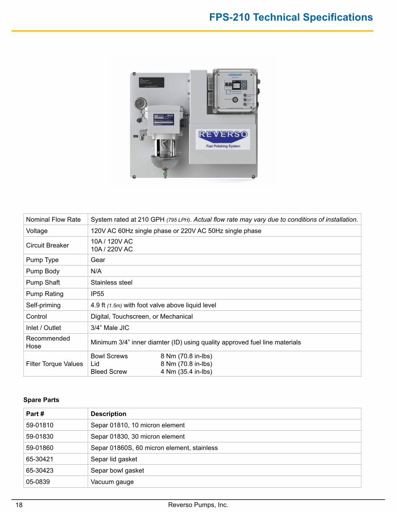
FPS-210 Technical Specifications
Nominal Flow Rate System rated at 210 GPH (795 LPH). Actual flow rate may vary due to conditions of installation.
Voltage 120V AC 60Hz single phase or 220V AC 50Hz single phase
Circuit Breaker 10A / 120V AC 10A / 220V AC
Pump Type Gear
Pump Body N/A
Pump Shaft Stainless steel
Pump Rating IP55
Self-priming 4.9 ft (1.5m) with foot valve above liquid level
Control Digital, Touchscreen, or Mechanical
Inlet / Outlet 3/4” Male JICRecommended Hose Minimum 3/4” inner diamter (ID) using quality approved fuel line materials
Filter Torque ValuesBowl Screws 8 Nm (70.8 in-lbs)Lid 8 Nm (70.8 in-lbs)Bleed Screw 4 Nm (35.4 in-lbs)
Spare Parts
Part # Description
59-01810 Separ 01810, 10 micron element
59-01830 Separ 01830, 30 micron element
59-01860 Separ 01860S, 60 micron element, stainless
65-30421 Separ lid gasket
65-30423 Separ bowl gasket
05-0839 Vacuum gauge
19Reverso Pumps, Inc.
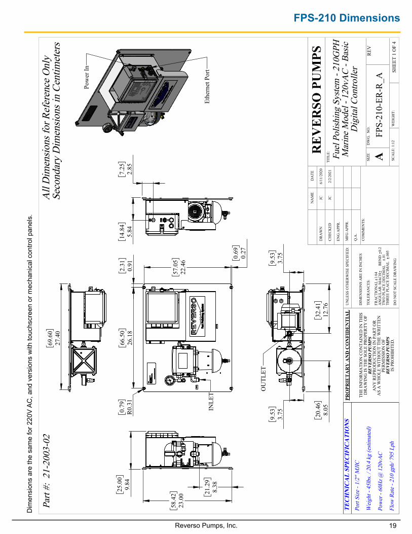
FPS-210 Dimensions
66
.50
26.1
8
0.79
R0.
31
2.31
0.91
57
.05
22.4
6
0.
690.
27
INLE
T
14
.84
5.84
7.25
2.85
58
.42
23.0
0
25
.00
9.84
21
.29
8.38
69
.60
27.4
0
Pow
er In
Ethe
rnet
Por
t
9.
533.
75
32
.41
12.7
6
20
.46
8.05
9.
533.
75
OU
TLET
Fuel
Pol
ishin
g Sy
stem
- 21
0GPH
M
arin
e Mod
el -
120v
AC
- Bas
ic
Dig
ital C
ontro
ller
DO
NO
T SC
ALE
DR
AW
ING
FPS-
210-
ER-R
_ASH
EET
1 O
F 4
2/2/
2021
JC
UN
LESS
OTH
ERW
ISE
SPEC
IFIE
D:
SCA
LE: 1
:12
WEI
GH
T:
REV
DW
G.
NO
.
ASIZE
TITL
E:REV
ERSO
PU
MPS
NA
ME
DA
TE
COM
MEN
TS:
Q.A
.
MFG
APP
R.
ENG
APP
R.
CHEC
KED
DR
AW
N
DIM
ENSI
ON
S A
RE IN
INCH
ES
TOLE
RAN
CES:
FRA
CTIO
NA
L1/
64A
NG
ULA
R: M
AC
H
BEN
D
0.2
TWO
PLA
CE
DEC
IMA
L
.01
THRE
E PL
ACE
DEC
IMA
L
.005
PRO
PRIE
TAR
Y A
ND
CO
NFI
DEN
TIA
L
THE
INFO
RMA
TIO
N C
ON
TAIN
ED IN
TH
ISD
RAW
ING
IS T
HE
SOLE
PRO
PERT
Y O
FR
EVER
SO P
UM
PS
AN
Y R
EPR
OD
UC
TIO
N IN
PA
RT
OR
A
S A
WH
OLE
WIT
HO
UT
THE
WR
ITTE
N
PERM
ISSI
ON
OF
REV
ERSO
PU
MPS
IS
PRO
HIB
ITED
.
Part
#: 2
1-20
03-0
2A
ll D
imen
sions
for R
efer
ence
Onl
ySe
cond
ary
Dim
ensio
ns in
Cen
timet
ers
TEC
HN
ICA
L SP
ECIF
ICA
TIO
NS
Port
Size
- 1/
2" M
JIC
Wei
ght -
45l
bs. /
20.
4 kg
(esti
mat
ed)
Pow
er -
60H
z @ 1
20vA
C
Flow
Rat
e - 2
10 g
ph/ 7
95 L
ph
JC
6/11
/202
0
Dim
ensi
ons
are
the
sam
e fo
r 220
V A
C, a
nd v
ersi
ons
with
touc
hscr
een
or m
echa
nica
l con
trol p
anel
s.
20 Reverso Pumps, Inc.
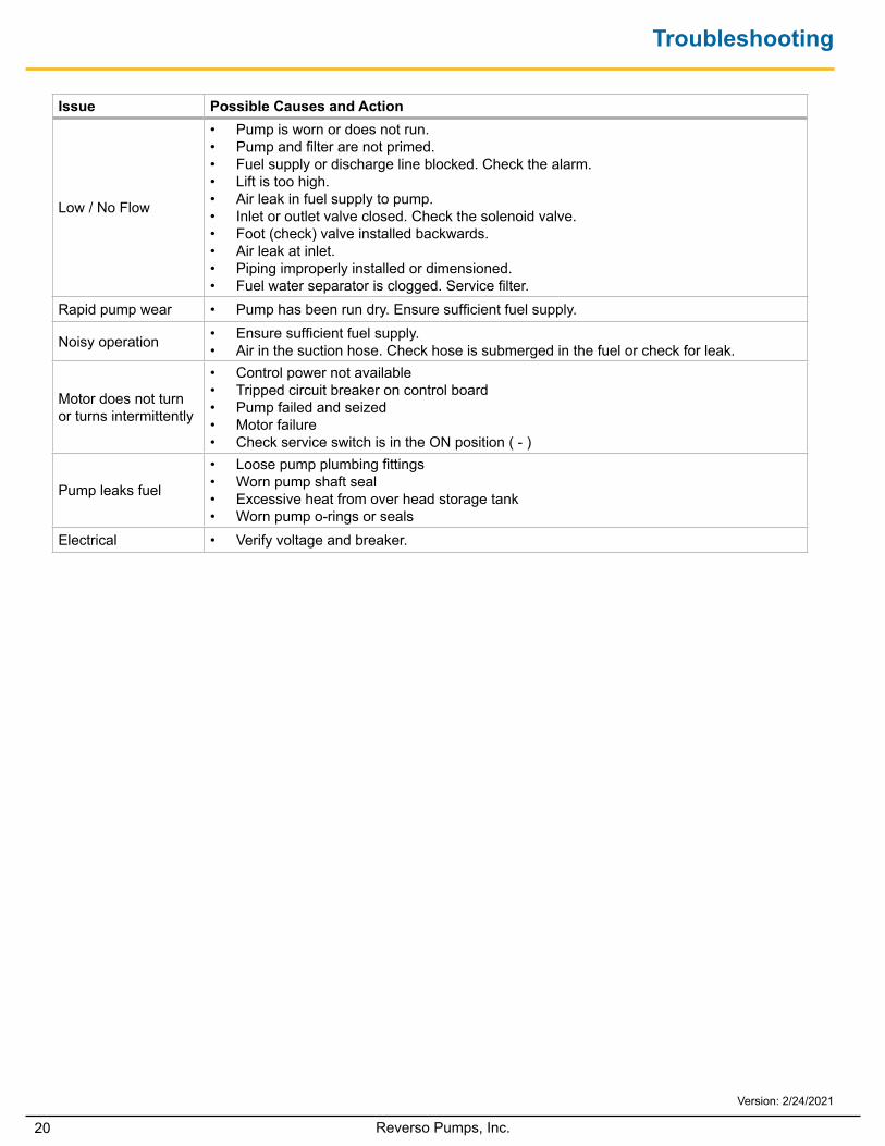
Troubleshooting
Version: 2/24/2021
Issue Possible Causes and Action
Low / No Flow
• Pump is worn or does not run.• Pump and filter are not primed.• Fuel supply or discharge line blocked. Check the alarm.• Lift is too high.• Air leak in fuel supply to pump.• Inlet or outlet valve closed. Check the solenoid valve.• Foot (check) valve installed backwards.• Air leak at inlet.• Piping improperly installed or dimensioned.• Fuel water separator is clogged. Service filter.
Rapid pump wear • Pump has been run dry. Ensure sufficient fuel supply.
Noisy operation • Ensure sufficient fuel supply.• Air in the suction hose. Check hose is submerged in the fuel or check for leak.
Motor does not turn or turns intermittently
• Control power not available• Tripped circuit breaker on control board• Pump failed and seized• Motor failure• Check service switch is in the ON position ( - )
Pump leaks fuel
• Loose pump plumbing fittings• Worn pump shaft seal• Excessive heat from over head storage tank• Worn pump o-rings or seals
Electrical • Verify voltage and breaker.