Embed Size (px)
Citation preview
INSTRUCTIONS & SPARE PARTSCONVEYING AND SUCTION MODULE FOR TRULASER 3030 (L20)
TRULASER 3030 (L20)

20 - 2 - CONVEYING AND SUCTION MODULE FOR
TruLaser 3030 (L20)2/20
1 INTRODUCTION 3
1.1 General information 3
1.2 Instructions for use of the module 3
1.3 Guarantees 4
1.4 Safety instructions 4
1.5 Electrical lock-out of the conveying and suction module 4
2 TRANSPORT AND HANDLING 4
3 COMMISSIONING 6
3.1 First time start-up 5
3.1.1 General 5
3.1.2 Conveyor drive 5
3.1.3 Suction valves 5
3.2 Use in normal operation 5
3.3 Protection in case of overload 5
3.4 Electrical connections 5
4 ADJUSTMENTS 7
4.1 Tension adjustment of conveyor belt 6
4.1.1 Check the tension of the conveyor belt 6
4.1.2 Adjusting the tension of the conveyor belt 6
4.2 Centering the conveyor belt 7
4.3 Adjusting the stops 7
5 MAINTENANCE OF THE MODULE 9
5.1 Maintenance 8
5.1.1 Emptying the waste bins 8
5.1.2 Servicing the drive mechanism 9
5.1.2.1 Oils 9
5.1.2.2 Chart of lubricants for NORD gear motor 9
5.1.2.3 Level and quantity of lubricant 10
5.1.3 Servicing the belt 10
5.1.3.1 Cleaning / Oiling the belt 10
5.1.3.2 Lubrication of chains 10
5.1.3.3 Adjusting the tension and centering the belt 10
5.1.3.4 Changing the belt 10
5.1.4 Servicing the suction part 12
5.1.4.1 Servicing the actuators 12
5.1.4.2 Servicing the bearings 12
5.1.4.3 Servicing the ASi directional control valve 12
5.1.4.4 Dismantling/Reassembling the suction valves 13
5.1.5 Servicing the conveying and suction module 13
5.2 Shut-down of conveyor 13
5.3 Possible incidents 14
6 SPARE PARTS 14
6.1 Sub-assembly 1 : Drive unit 15
6.2 Sub-assembly 2 : Return unit 15
6.3 Sub-assembly 3 : Belt 16
6.4 Sub-assembly 4 : Lubrication 16
6.5 Sub-assembly 5 : Distribution unit 16
6.6 Sub-assembly 6 : Casing components 17
6.7 Sub-assembly 7 : Suction unit 18
CONVEYING AND SUCTION MODULE FOR
TruLaser 3030 (L20) 3/20
1 INTRODUCTION
1.1 General information
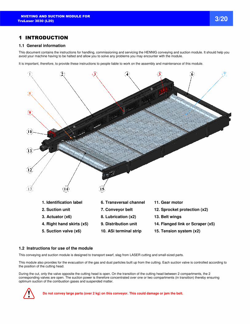
This document contains the instructions for handling, commissioning and servicing the HENNIG conveying and suction module. It should help you avoid your machine having to be halted and allow you to solve any problems you may encounter with the module.
It is important, therefore, to provide these instructions to people liable to work on the assembly and maintenance of this module.
1. Identification label 6. Transversal channel 11. Gear motor
2. Suction unit 7. Conveyor belt 12. Sprocket protection (x2)
3. Actuator (x6) 8. Lubrication (x2) 13. Belt wings
4. Right hand skirts (x5) 9. Distribution unit 14. Flanged link or Scraper (x5)
5. Suction valve (x6) 10. ASi terminal strip 15. Tension system (x2)
1.2 Instructions for use of the module
This conveying and suction module is designed to transport swarf, slag from LASER cutting and small-sized parts.
This module also provides for the evacuation of the gas and dust particles built up from the cutting. Each suction valve is controlled according to the position of the cutting head.
During the cut, only the valve opposite the cutting head is open. On the transition of the cutting head between 2 compartments, the 2 corresponding valves are open. The suction power is therefore concentrated over one or two compartments (in transition) thereby ensuring optimum suction of the combustion gases and suspended matter.
Do not convey large parts (over 2 kg) on this conveyor. This could damage or jam the belt.
20 - 4 -
CONVEYING AND SUCTION MODULE FOR
TruLaser 3030 (L20) 4/20
1.3 Guarantees
In compliance with our general conditions of sale, this module is guaranteed solely for hidden defects resulting from the design, material or execution and which occur during the guarantee period. Similarly, this guarantee only applies to equipment installed according to good professional practice and provided that the purchaser can prove full compliance with the maintenance conditions. In any event, any fault noted must be reported to HENNIG which undertakes to correct the problem if responsible for it. Wear of spare parts termed "wear parts" does not constitute a fault (see Section 6). It is pointed out that a certain number of components on the module have their own “manufacturer's" guarantee, such as the actuators, the pneumatic directional control valve, the gear motor, etc. Therefore, no intervention must be made on our products, apart from servicing operations, without obtaining our agreement. Important note: Parts termed "wear parts", which are scheduled to be replaced and for which the guarantee does not apply, are excluded from the legal and contractual warranty, except in the case of excessive wear due to a quality fault affecting the part. In case of an exchange under guarantee, replacement of the faulty parts does not prolong the warranty period.
1.4 Safety Instructions
• Observe the contents of this manual.
• Only allow approved electricians to carry out electrical work.
• Servicing and repair operations must be entrusted only to qualified staff, trained as required.
• Never override the safety devices (for example the motor protection cut-outs). Their operation should always be assured.
• Never put your hands into the conveyor system when it is running.
• Never walk on the belt while the conveyor is running.
• If the conveyor jams, only remove chips or parts with suitable tools (chip shovel) and protective equipment (gloves). The power should be cut off at the main switch for such operations.
• Never put your hands inside the suction system (valves and actuators) when the module is in operation.
• When servicing the suction channel, only remove dust, swarf or parts with suitable tooling (swarf scoop) and protection equipment (gloves, goggles, etc).
• Never take action on the module when in operation and when the control of the machine is connected.
• When the operators need to intervene in the neighborhood of the module, it must be suitably illuminated to allow the operators to move and work without any risk of danger, in particular falling.
• Non-observance of the safety instructions may result in bodily injury or damage to the equipment.
1.5 Electrical lock-out of the conveying and suction module
Prior to servicing, module must be properly “Locked Out” per OSHA 29 CFR Part 1910.147
2 TRANSPORT AND HANDLING
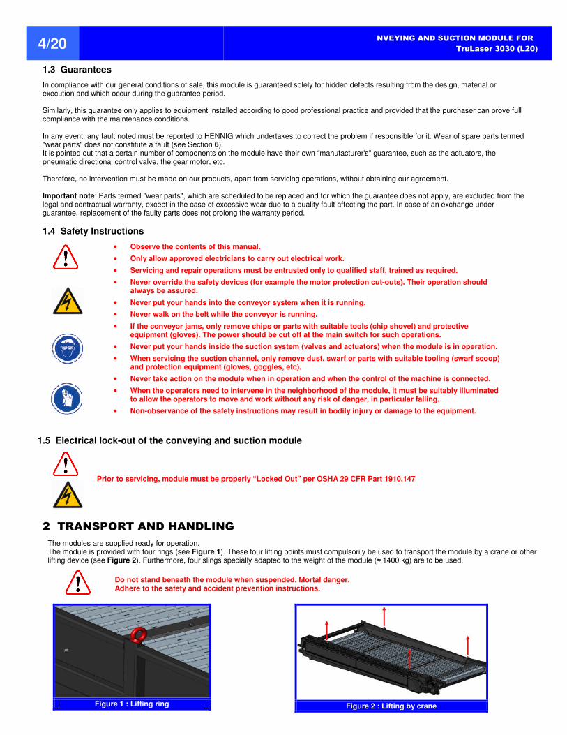
The modules are supplied ready for operation. The module is provided with four rings (see Figure 1). These four lifting points must compulsorily be used to transport the module by a crane or other lifting device (see Figure 2). Furthermore, four slings specially adapted to the weight of the module (≈ 1400 kg) are to be used.
Do not stand beneath the module when suspended. Mortal danger. Adhere to the safety and accident prevention instructions.
Figure 1 : Lifting ring
Figure 2 : Lifting by crane
CONVEYING AND SUCTION MODULE FOR
TruLaser 3030 (L20) 5/20
3 COMMISSIONING
3.1 First time start-up
The following checks must be made prior to first time start-up:
3.1.1 General
Check that the module is incorporated into the TRUMPF installation in a workmanlike manner and in accordance with the safety instructions.
Check the tension of the hinged belt. The modules come out of our factory with a belt duly taut. However, the belt can slacken during transport or
inspection.
Check the automatic lubrication of the side chains.
Check the electrical connection to your company's installation.
3.1.2 Conveyor drive
The conveyor belt is driven by a helical-bevel gear motor. It is assembled by HENNIG on the right hand side of the conveyor. This unit is serviced as described in section 5.1.2. Unless otherwise specified, each drive mechanism comes out of our factory filled with lubricant adapted to the reduction gear and its use. It is,
however, worth checking the oil level. Oil (dripping) at the sealing ring is considered normal during operation.
3.1.3 Suction valves
Each suction valve assembly (6 in total) is previously adjusted in the factory to ensure optimum operation, however, a check must be made to
ensure the shutter pivots without local friction or banging. If not, refer to section 4.3.
3.2 Use in normal operation
Do not walk on the conveyor belt when it is in service.
It is essential to make sure that the parts conveyed are loaded evenly on the belt.
3.3 Protection in case of overload
Protection in the event of overload is provided by an electrical component incorporated in the machine electrical cabinet.
Make sure circuit breakers are functioning properly.
3.4 Electrical connections
All electrical connections on the module are ready for installation. All factory installed electrical connectors and AS-I wiring is in compliance with
NFPA 70 and NFPA 79. All electrical connections MUST be carried out by Authorized Trained Personnel in accordance with OSHA 29 CFR Part
1910.301.
The conveyors are fitted with a backward operation device.
20 - 6 -
CONVEYING AND SUCTION MODULE FOR
TruLaser 3030 (L20) 6/20
4 ADJUSTMENTS
For any action on the module, the wearing of personal protection equipment: goggles, dust mask, safety footwear and protective gloves is compulsory in order to protect from any splashes of swarf or dust when cleaning and in order to handle the components and tools required in optimum safety conditions.
Never take action on the module when in operation and when the control of the machine is connected. To do this, perform electrical lock-out of the machine (Section 1.5, page 4).
Maintenance or servicing operations must only be entrusted to qualified staff, trained as required, namely if it is required to be in contact with the moving parts, belts, valves, etc.
4.1 Tension adjustment of conveyor belt
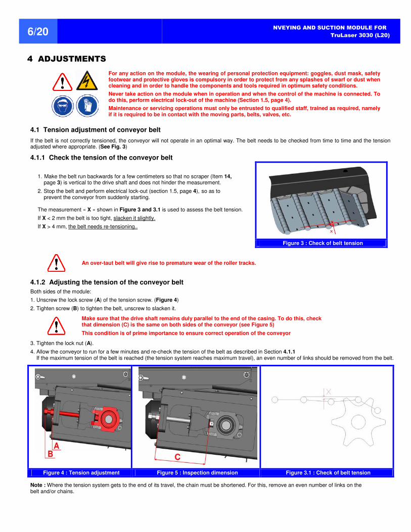
If the belt is not correctly tensioned, the conveyor will not operate in an optimal way. The belt needs to be checked from time to time and the tension adjusted where appropriate. (See Fig. 3)
4.1.1 Check the tension of the conveyor belt
1. Make the belt run backwards for a few centimeters so that no scraper (Item 14, page 3) is vertical to the drive shaft and does not hinder the measurement.
2. Stop the belt and perform electrical lock-out (section 1.5, page 4), so as to prevent the conveyor from suddenly starting.
The measurement « X » shown in Figure 3 and 3.1 is used to assess the belt tension.
If X < 2 mm the belt is too tight, slacken it slightly.
If X > 4 mm, the belt needs re-tensioning..
Figure 3 : Check of belt tension
An over-taut belt will give rise to premature wear of the roller tracks.
4.1.2 Adjusting the tension of the conveyor belt
Both sides of the module:
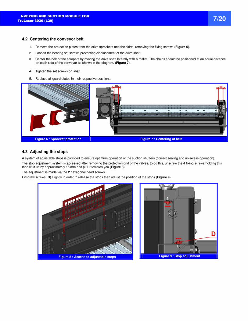
1. Unscrew the lock screw (A) of the tension screw. (Figure 4)
2. Tighten screw (B) to tighten the belt, unscrew to slacken it.
Make sure that the drive shaft remains duly parallel to the end of the casing. To do this, check that dimension (C) is the same on both sides of the conveyor (see Figure 5)
This condition is of prime importance to ensure correct operation of the conveyor
3. Tighten the lock nut (A).
4. Allow the conveyor to run for a few minutes and re-check the tension of the belt as described in Section 4.1.1 If the maximum tension of the belt is reached (the tension system reaches maximum travel), an even number of links should be removed from the belt.
Figure 4 : Tension adjustment Figure 5 : Inspection dimension Figure 3.1 : Check of belt tension
Note : Where the tension system gets to the end of its travel, the chain must be shortened. For this, remove an even number of links on the belt and/or chains.
CONVEYING AND SUCTION MODULE FOR
TruLaser 3030 (L20) 7/20
4.2 Centering the conveyor belt
1. Remove the protection plates from the drive sprockets and the skirts, removing the fixing screws (Figure 6).
2. Loosen the bearing set screws preventing displacement of the drive shaft.
3. Center the belt or the scrapers by moving the drive shaft laterally with a mallet. The chains should be positioned at an equal distance on each side of the conveyor as shown in the diagram. (Figure 7).
4. Tighten the set screws on shaft. 5. Replace all guard plates in their respective positions.
Figure 6 : Sprocket protection Figure 7 : Centering of belt
4.3 Adjusting the stops
A system of adjustable stops is provided to ensure optimum operation of the suction shutters (correct sealing and noiseless operation).
The stop adjustment system is accessed after removing the protection grid of the valves, to do this, unscrew the 4 fixing screws holding this then lift it up by approximately 15 mm and pull it towards you (Figure 8)
The adjustment is made via the 2 hexagonal head screws.
Unscrew screws (D) slightly in order to release the stops then adjust the position of the stops (Figure 9).
Figure 8 : Access to adjustable stops
Figure 9 : Stop adjustment
20 - 8 -
CONVEYING AND SUCTION MODULE FOR
TruLaser 3030 (L20) 8/20
5 MAINTENANCE OF THE MODULE
For any action on the module, the wearing of personal protection equipment: goggles, dust mask, safety footwear and protective gloves is compulsory in order to protect yourself from any splashes of swarf or dust when cleaning and in order to handle the components and tools required in optimum safety conditions.
Never take action on the module when in operation and when the control of the machine is connected. To do this, perform electrical lock-out of the machine (Section 1.5, page 4).
Maintenance or servicing operations must only be entrusted to qualified staff, trained as required, namely if it is required to be in contact with the moving parts, belts, valves, etc.
5.1 Maintenance
Maintenance summary (for use in one shift):
Component Actions
Frequency (hours)
40 500 1.000 5.000 10.000
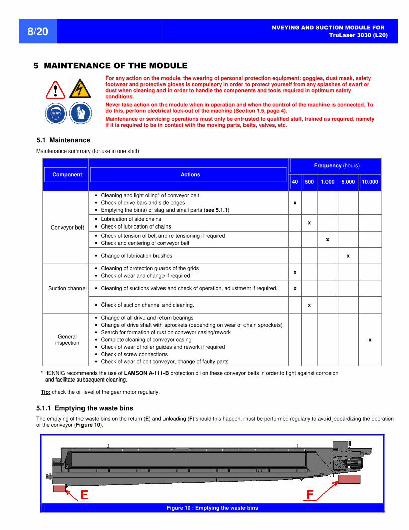
Conveyor belt
• Cleaning and light oiling* of conveyor belt
• Check of drive bars and side edges
• Emptying the bin(s) of slag and small parts (see 5.1.1)
x
• Lubrication of side chains
• Check of lubrication of chains x
• Check of tension of belt and re-tensioning if required
• Check and centering of conveyor belt x
• Change of lubrication brushes x
Suction channel
• Cleaning of protection guards of the grids
• Check of wear and change if required x
• Cleaning of suctions valves and check of operation, adjustment if required. x
• Check of suction channel and cleaning. x
General inspection
• Change of all drive and return bearings
• Change of drive shaft with sprockets (depending on wear of chain sprockets)
• Search for formation of rust on conveyor casing/rework
• Complete cleaning of conveyor casing
• Check of wear of roller guides and rework if required
• Check of screw connections
• Check of wear of belt conveyor, change of faulty parts
x
* HENNIG recommends the use of LAMSON A-111-B protection oil on these conveyor belts in order to fight against corrosion and facilitate subsequent cleaning.
Tip: check the oil level of the gear motor regularly.
5.1.1 Emptying the waste bins
The emptying of the waste bins on the return (E) and unloading (F) should this happen, must be performed regularly to avoid jeopardizing the operation of the conveyor (Figure 10).
Figure 10 : Emptying the waste bins
CONVEYING AND SUCTION MODULE FOR
TruLaser 3030 (L20) 9/20
5.1.2 Servicing the drive mechanism
For optimal operation, the accumulation of dust, slag and dirt on the geared motor drive is to be avoided. The openings in the hood and the cooling fins are important elements of the motor. Make sure that they remain clean. The main maintenance required on the gear motor is to check the oil level on a regular basis. The instructions for checking the lubricant level are described in Section 5.1.2.3 Note: The presence of oil around the sealing ring should be considered normal during operation.
5.1.2.1 Oils
Unless otherwise specified, each drive mechanism comes out of our factory filled with lubricant adapted to the type of reduction gear, its assembly position and its use. Refer to the lubricants chart for NORD gear motor in section 5.1.2.2 for the use of other oils or greases. The bearings of the reduction gears and motors are filled at the factory with greases indicated in section 5.1.2.2
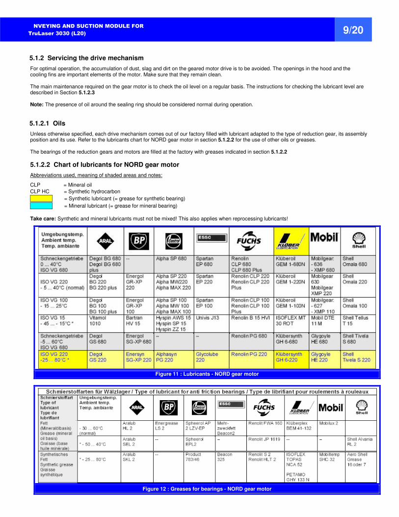
5.1.2.2 Chart of lubricants for NORD gear motor
Abbreviations used, meaning of shaded areas and notes:
CLP = Mineral oil
CLP HC = Synthetic hydrocarbon
1 = Synthetic lubricant (= grease for synthetic bearing)
1 = Mineral lubricant (= grease for mineral bearing)
Take care: Synthetic and mineral lubricants must not be mixed! This also applies when reprocessing lubricants!
Figure 11 : Lubricants - NORD gear motor
Figure 12 : Greases for bearings - NORD gear motor
20 - 10 -
CONVEYING AND SUCTION MODULE FOR
TruLaser 3030 (L20) 10/20
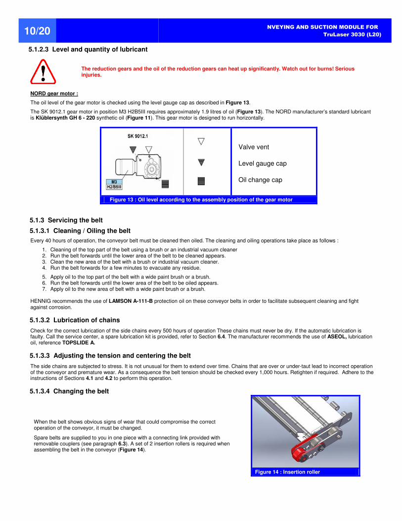
5.1.2.3 Level and quantity of lubricant
The reduction gears and the oil of the reduction gears can heat up significantly. Watch out for burns! Serious injuries.
NORD gear motor :
The oil level of the gear motor is checked using the level gauge cap as described in Figure 13.
The SK 9012.1 gear motor in position M3 H2B5III requires approximately 1.9 litres of oil (Figure 13). The NORD manufacturer’s standard lubricant is Klüblersynth GH 6 - 220 synthetic oil (Figure 11). This gear motor is designed to run horizontally.
Valve vent
Level gauge cap
Oil change cap
Figure 13 : Oil level according to the assembly position of the gear motor
5.1.3 Servicing the belt
5.1.3.1 Cleaning / Oiling the belt
Every 40 hours of operation, the conveyor belt must be cleaned then oiled. The cleaning and oiling operations take place as follows :
1. Cleaning of the top part of the belt using a brush or an industrial vacuum cleaner 2. Run the belt forwards until the lower area of the belt to be cleaned appears. 3. Clean the new area of the belt with a brush or industrial vacuum cleaner. 4. Run the belt forwards for a few minutes to evacuate any residue.
5. Apply oil to the top part of the belt with a wide paint brush or a brush. 6. Run the belt forwards until the lower area of the belt to be oiled appears. 7. Apply oil to the new area of belt with a wide paint brush or a brush.
HENNIG recommends the use of LAMSON A-111-B protection oil on these conveyor belts in order to facilitate subsequent cleaning and fight against corrosion.
5.1.3.2 Lubrication of chains
Check for the correct lubrication of the side chains every 500 hours of operation These chains must never be dry. If the automatic lubrication is faulty. Call the service center, a spare lubrication kit is provided, refer to Section 6.4. The manufacturer recommends the use of ASEOL, lubrication oil, reference TOPSLIDE A.
5.1.3.3 Adjusting the tension and centering the belt
The side chains are subjected to stress. It is not unusual for them to extend over time. Chains that are over or under-taut lead to incorrect operation of the conveyor and premature wear. As a consequence the belt tension should be checked every 1,000 hours. Retighten if required. Adhere to the instructions of Sections 4.1 and 4.2 to perform this operation.
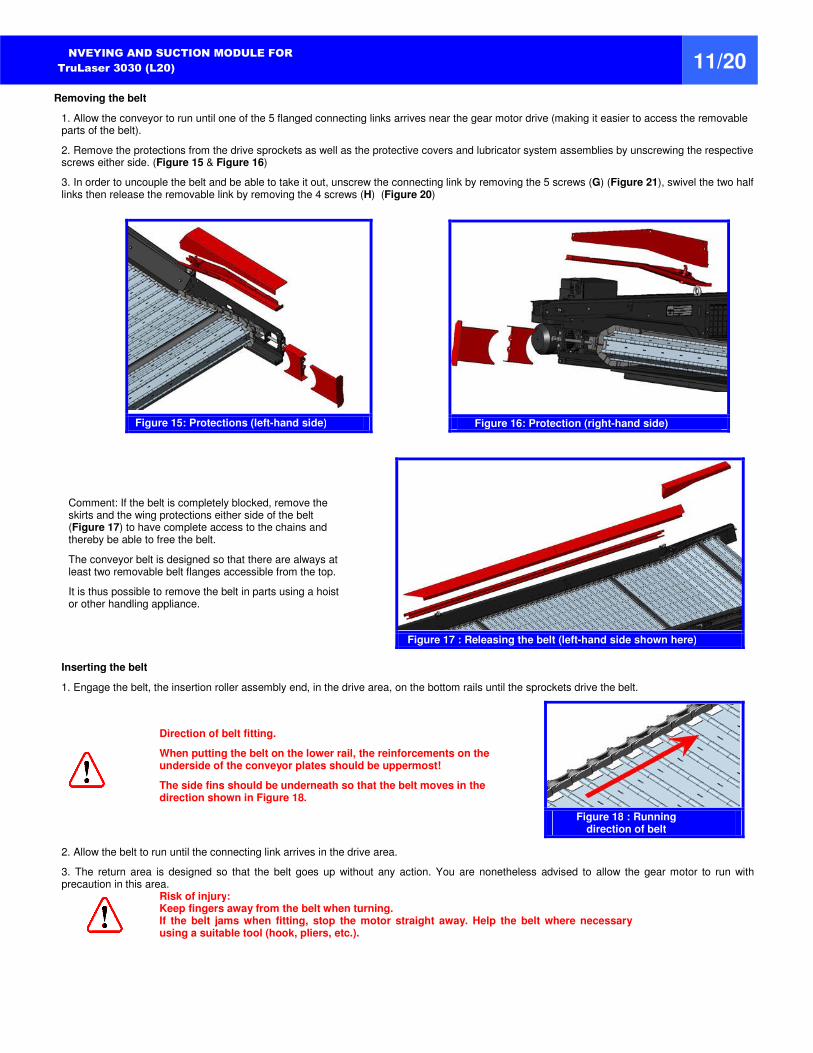
5.1.3.4 Changing the belt
When the belt shows obvious signs of wear that could compromise the correct operation of the conveyor, it must be changed.
Spare belts are supplied to you in one piece with a connecting link provided with removable couplers (see paragraph 6.3). A set of 2 insertion rollers is required when assembling the belt in the conveyor (Figure 14).
Figure 14 : Insertion roller
CONVEYING AND SUCTION MODULE FOR
TruLaser 3030 (L20) 11/20
Removing the belt
1. Allow the conveyor to run until one of the 5 flanged connecting links arrives near the gear motor drive (making it easier to access the removable parts of the belt).
2. Remove the protections from the drive sprockets as well as the protective covers and lubricator system assemblies by unscrewing the respective screws either side. (Figure 15 & Figure 16)
3. In order to uncouple the belt and be able to take it out, unscrew the connecting link by removing the 5 screws (G) (Figure 21), swivel the two half links then release the removable link by removing the 4 screws (H) (Figure 20)
Figure 15: Protections (left-hand side)
Figure 16: Protection (right-hand side)
Comment: If the belt is completely blocked, remove the skirts and the wing protections either side of the belt (Figure 17) to have complete access to the chains and thereby be able to free the belt.
The conveyor belt is designed so that there are always at least two removable belt flanges accessible from the top.
It is thus possible to remove the belt in parts using a hoist or other handling appliance.
Figure 17 : Releasing the belt (left-hand side shown here)
Inserting the belt
1. Engage the belt, the insertion roller assembly end, in the drive area, on the bottom rails until the sprockets drive the belt.
Direction of belt fitting.
When putting the belt on the lower rail, the reinforcements on the underside of the conveyor plates should be uppermost!
The side fins should be underneath so that the belt moves in the direction shown in Figure 18.
Figure 18 : Running
direction of belt
2. Allow the belt to run until the connecting link arrives in the drive area.
3. The return area is designed so that the belt goes up without any action. You are nonetheless advised to allow the gear motor to run with precaution in this area.
Risk of injury: Keep fingers away from the belt when turning. If the belt jams when fitting, stop the motor straight away. Help the belt where necessary using a suitable tool (hook, pliers, etc.).
20 - 12 -
CONVEYING AND SUCTION MODULE FOR
TruLaser 3030 (L20) 12/20
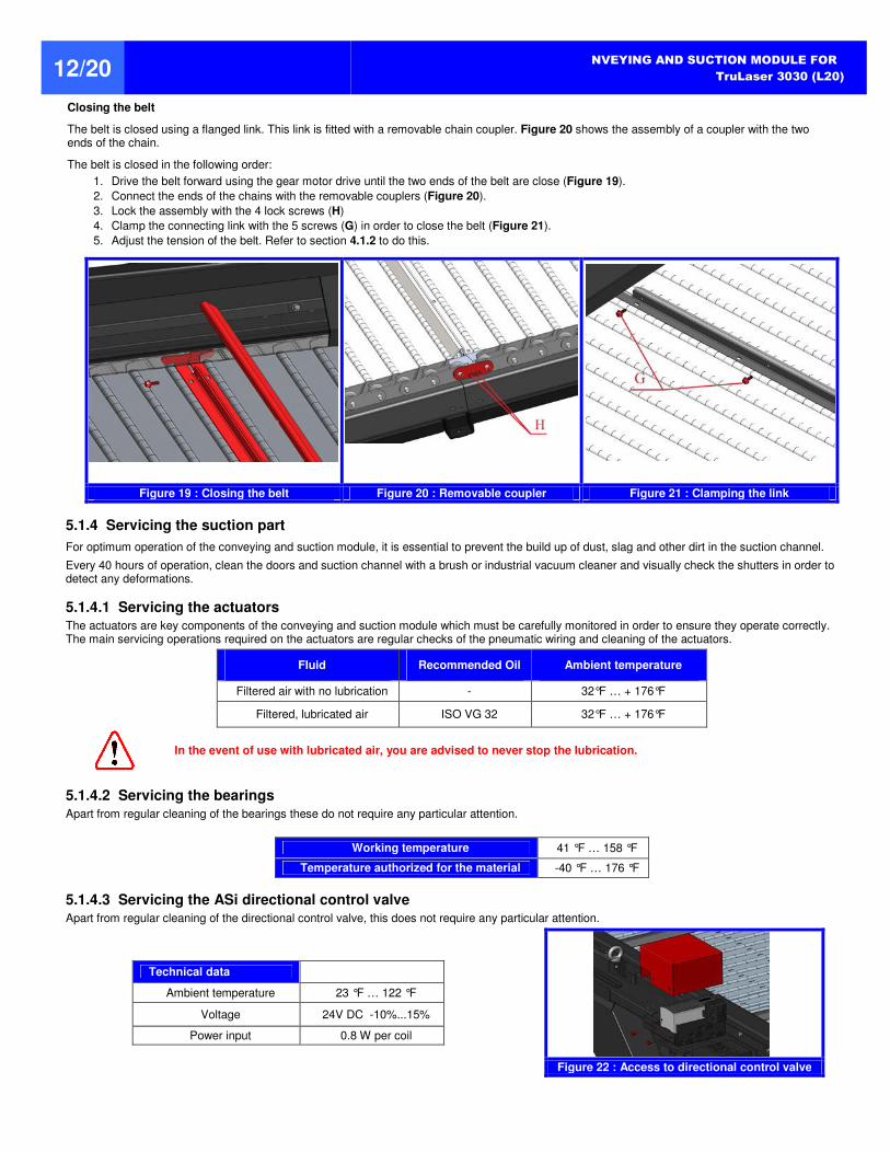
Closing the belt
The belt is closed using a flanged link. This link is fitted with a removable chain coupler. Figure 20 shows the assembly of a coupler with the two ends of the chain.
The belt is closed in the following order:
1. Drive the belt forward using the gear motor drive until the two ends of the belt are close (Figure 19).
2. Connect the ends of the chains with the removable couplers (Figure 20).
3. Lock the assembly with the 4 lock screws (H)
4. Clamp the connecting link with the 5 screws (G) in order to close the belt (Figure 21).
5. Adjust the tension of the belt. Refer to section 4.1.2 to do this.
Figure 19 : Closing the belt Figure 20 : Removable coupler Figure 21 : Clamping the link
5.1.4 Servicing the suction part
For optimum operation of the conveying and suction module, it is essential to prevent the build up of dust, slag and other dirt in the suction channel.
Every 40 hours of operation, clean the doors and suction channel with a brush or industrial vacuum cleaner and visually check the shutters in order to detect any deformations.
5.1.4.1 Servicing the actuators
The actuators are key components of the conveying and suction module which must be carefully monitored in order to ensure they operate correctly. The main servicing operations required on the actuators are regular checks of the pneumatic wiring and cleaning of the actuators.
Fluid Recommended Oil Ambient temperature
Filtered air with no lubrication - 32°F … + 176°F
Filtered, lubricated air ISO VG 32 32°F … + 176°F
In the event of use with lubricated air, you are advised to never stop the lubrication.
5.1.4.2 Servicing the bearings
Apart from regular cleaning of the bearings these do not require any particular attention.
Working temperature 41 °F … 158 °F
Temperature authorized for the material -40 °F … 176 °F
5.1.4.3 Servicing the ASi directional control valve
Apart from regular cleaning of the directional control valve, this does not require any particular attention.
Technical data
Ambient temperature 23 °F … 122 °F
Voltage 24V DC -10%...15%
Power input 0.8 W per coil
Figure 22 : Access to directional control valve
CONVEYING AND SUCTION MODULE FOR
TruLaser 3030 (L20) 13/20
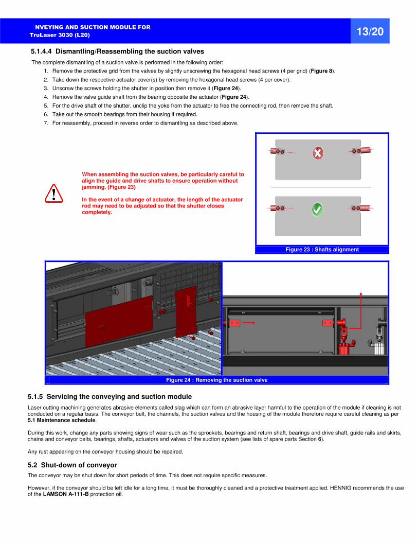
5.1.4.4 Dismantling/Reassembling the suction valves
The complete dismantling of a suction valve is performed in the following order:
1. Remove the protective grid from the valves by slightly unscrewing the hexagonal head screws (4 per grid) (Figure 8).
2. Take down the respective actuator cover(s) by removing the hexagonal head screws (4 per cover).
3. Unscrew the screws holding the shutter in position then remove it (Figure 24).
4. Remove the valve guide shaft from the bearing opposite the actuator (Figure 24).
5. For the drive shaft of the shutter, unclip the yoke from the actuator to free the connecting rod, then remove the shaft.
6. Take out the smooth bearings from their housing if required.
7. For reassembly, proceed in reverse order to dismantling as described above.
When assembling the suction valves, be particularly careful to align the guide and drive shafts to ensure operation without jamming. (Figure 23) In the event of a change of actuator, the length of the actuator rod may need to be adjusted so that the shutter closes completely.
Figure 23 : Shafts alignment
Figure 24 : Removing the suction valve
5.1.5 Servicing the conveying and suction module
Laser cutting machining generates abrasive elements called slag which can form an abrasive layer harmful to the operation of the module if cleaning is not conducted on a regular basis. The conveyor belt, the channels, the suction valves and the housing of the module therefore require careful cleaning as per 5.1 Maintenance schedule. During this work, change any parts showing signs of wear such as the sprockets, bearings and return shaft, bearings and drive shaft, guide rails and skirts, chains and conveyor belts, bearings, shafts, actuators and valves of the suction system (see lists of spare parts Section 6). Any rust appearing on the conveyor housing should be repaired.
5.2 Shut-down of conveyor
The conveyor may be shut down for short periods of time. This does not require specific measures. However, if the conveyor should be left idle for a long time, it must be thoroughly cleaned and a protective treatment applied. HENNIG recommends the use of the LAMSON A-111-B protection oil.
20 - 14 -
CONVEYING AND SUCTION MODULE FOR
TruLaser 3030 (L20) 14/20
5.3 Possible incidents
Incident Likely cause What to do
The conveyor is struggling although no part seems to be jamming it.
The belt is not sufficiently tensioned. Check and adjust the belt tension. Refer to section 4.1
The belt is jammed. Presence of parts which are incompatible with the conveyor’s capabilities
Move the conveyor backwards in steps. If this method does not work, the belt will need to be removed, see 5.1.3.4
The side fins are worn. The belt is not parallel to the casing Tighten and re-center the belt as per Section 4.1 to 4.2, and make sure that the belt remains parallel to the casing.
The geared motor drive heats up. Lack of oil in the geared motor drive Add more oil to the geared motor drive.
A valve is blocked
The actuator does not work Check the actuator is correctly supplied (condition of supply pipes, etc.)
Presence of parts blocking the shutter Remove the part(s) blocking the shutter. Refer to section 5.1.4
All the valves are blocked. Pneumatic problem
Check for the correct operation of the directional control valve.
Check that the directional control valve is correctly supplied with air and electricity
For the correct operation of the conveyor, it must be allowed to run non-stop, even if the machine no longer produces swarf or scrap.
6 SPARE PARTS
To speed up any enquiry or order you wish to make, you are asked to write down the TRUMPF identification no. and the data on the identification label affixed close to the slope of the slide rail, on the right hand side (Item #1, page 3). The parts lists below are provided for you to identify your requirements and to forward them to us correctly.
The spare parts of the module are broken down into 7 sub-assemblies:
Sub-assembly 1 : Drive unit (6.1)
Sub-assembly 2 : Return unit (6.2)
Sub-assembly 3 : Belt (6.3)
Sub-assembly 4 : Lubrication (6.4)
Sub-assembly 5 : Distribution unit (6.5)
Sub-assembly 6 : Casing components (6.6)
Sub-assembly 7 : Suction unit (6.7)
Figure 25 : Identification label
For each of these sub-assemblies, the following paragraphs describe :
the sets uses
the quantities
the identification of these sets
the assembly of sub-assemblies
CONVEYING AND SUCTION MODULE FOR
TruLaser 3030 (L20) 15/20
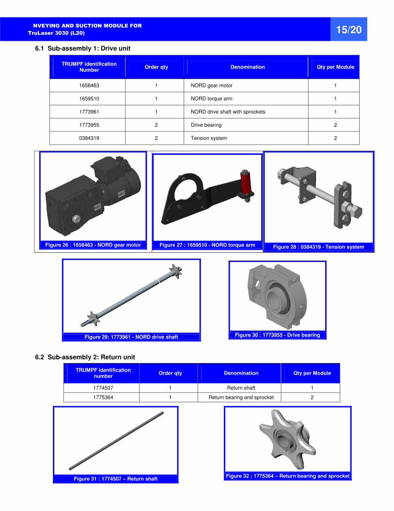
6.1 Sub-assembly 1: Drive unit
TRUMPF identification Number
Order qty Denomination Qty per Module
1658463 1 NORD gear motor 1
1659510 1 NORD torque arm 1
1773961 1 NORD drive shaft with sprockets 1
1773955 2 Drive bearing 2
0384319 2 Tension system 2
Figure 26 : 1658463 - NORD gear motor
Figure 27 : 1659510 - NORD torque arm
Figure 28 : 0384319 - Tension system
Figure 29: 1773961 - NORD drive shaft
Figure 30 : 1773955 - Drive bearing
6.2 Sub-assembly 2: Return unit
TRUMPF identification number
Order qty Denomination Qty per Module
1774507 1 Return shaft 1
1775364 1 Return bearing and sprocket 2
Figure 31 : 1774507 – Return shaft
Figure 32 : 1775364 – Return bearing and sprocket
20 - 16 -
CONVEYING AND SUCTION MODULE FOR
TruLaser 3030 (L20) 16/20
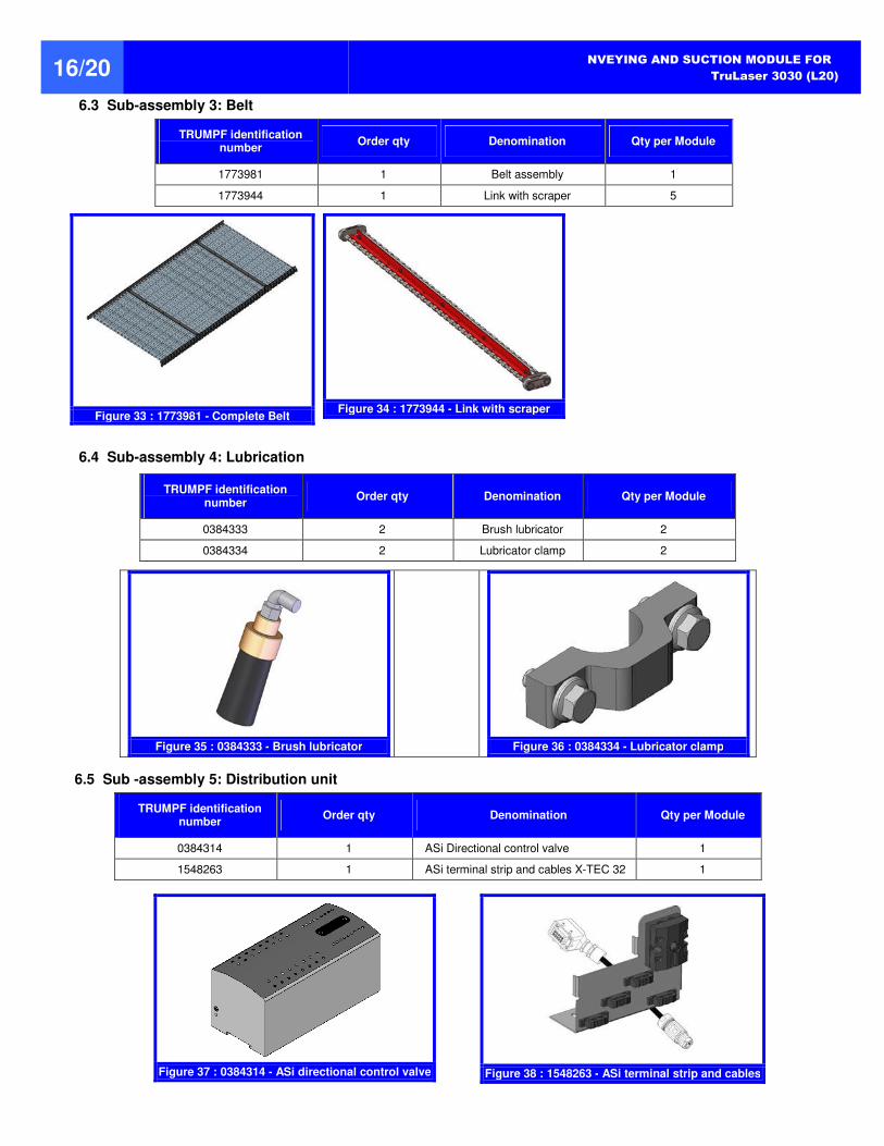
6.3 Sub-assembly 3: Belt
TRUMPF identification number
Order qty Denomination Qty per Module
1773981 1 Belt assembly 1
1773944 1 Link with scraper 5
Figure 33 : 1773981 - Complete Belt
Figure 34 : 1773944 - Link with scraper
6.4 Sub-assembly 4: Lubrication
TRUMPF identification number
Order qty Denomination Qty per Module
0384333 2 Brush lubricator 2
0384334 2 Lubricator clamp 2
Figure 35 : 0384333 - Brush lubricator
Figure 36 : 0384334 - Lubricator clamp
6.5 Sub -assembly 5: Distribution unit
TRUMPF identification number
Order qty Denomination Qty per Module
0384314 1 ASi Directional control valve 1
1548263 1 ASi terminal strip and cables X-TEC 32 1
Figure 37 : 0384314 - ASi directional control valve
Figure 38 : 1548263 - ASi terminal strip and cables
CONVEYING AND SUCTION MODULE FOR
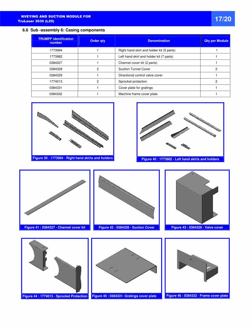
TruLaser 3030 (L20) 17/20 6.6 Sub -assembly 6: Casing components
TRUMPF identification number
Order qty Denomination Qty per Module
1773994 1 Right hand skirt and holder kit (5 parts) 1
1773982 1 Left hand skirt and holder kit (7 parts) 1
0384327 1 Channel cover kit (2 parts) 1
0384328 2 Suction Tunnel Cover 2
0384329 1 Directional control valve cover 1
1774013 2 Sprocket protection 2
0384331 1 Cover plate for gratings 1
0384332 1 Machine frame cover plate 1
Figure 39 : 1773994 - Right hand skirts and holders
Figure 40 : 1773982 - Left hand skirts and holders
Figure 41 : 0384327 - Channel cover kit
Figure 42 : 0384328 - Suction Cover
Figure 43 : 0384329 - Valve cover
Figure 44 : 1774013 - Sprocket Protection
Figure 45 : 0384331- Gratings cover plate
Figure 46 : 0384332 - Frame cover plate
20 - 18 -
CONVEYING AND SUCTION MODULE FOR
TruLaser 3030 (L20) 18/20
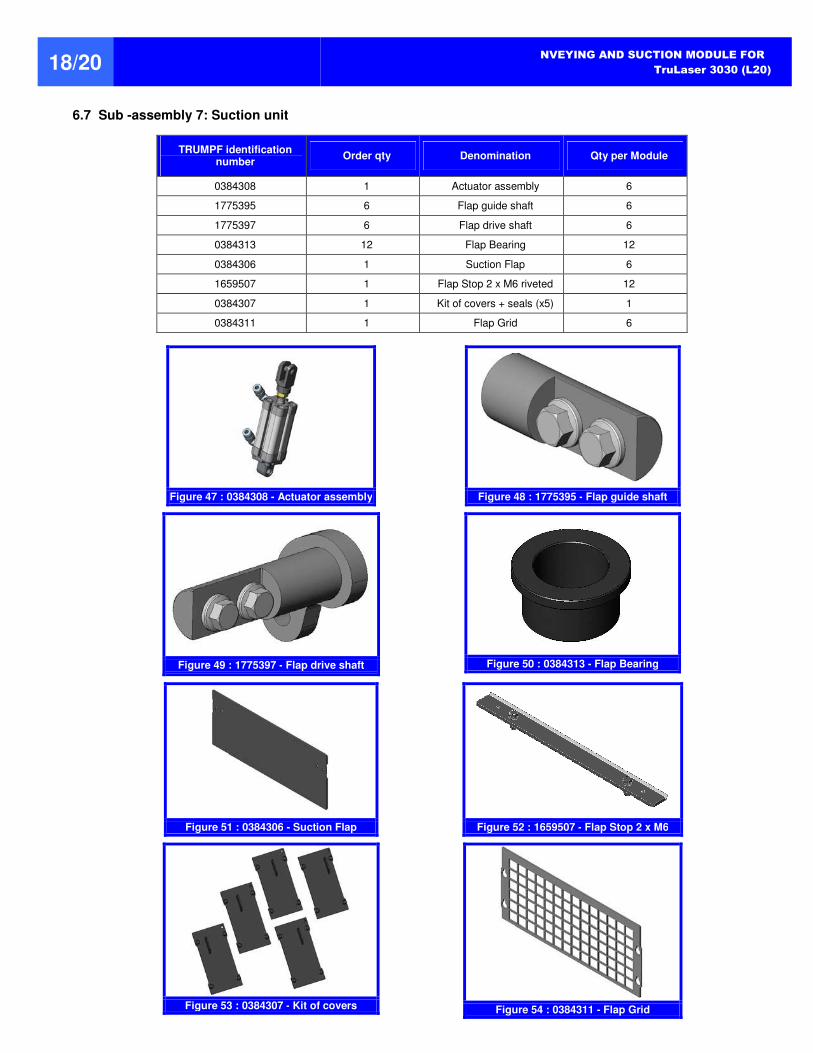
6.7 Sub -assembly 7: Suction unit
TRUMPF identification number
Order qty Denomination Qty per Module
0384308 1 Actuator assembly 6
1775395 6 Flap guide shaft 6
1775397 6 Flap drive shaft 6
0384313 12 Flap Bearing 12
0384306 1 Suction Flap 6
1659507 1 Flap Stop 2 x M6 riveted 12
0384307 1 Kit of covers + seals (x5) 1
0384311 1 Flap Grid 6
Figure 47 : 0384308 - Actuator assembly
Figure 48 : 1775395 - Flap guide shaft
Figure 49 : 1775397 - Flap drive shaft
Figure 50 : 0384313 - Flap Bearing
Figure 51 : 0384306 - Suction Flap
Figure 52 : 1659507 - Flap Stop 2 x M6
Figure 53 : 0384307 - Kit of covers
Figure 54 : 0384311 - Flap Grid
CONVEYING AND SUCTION MODULE FOR
TruLaser 3030 (L20) 19/20
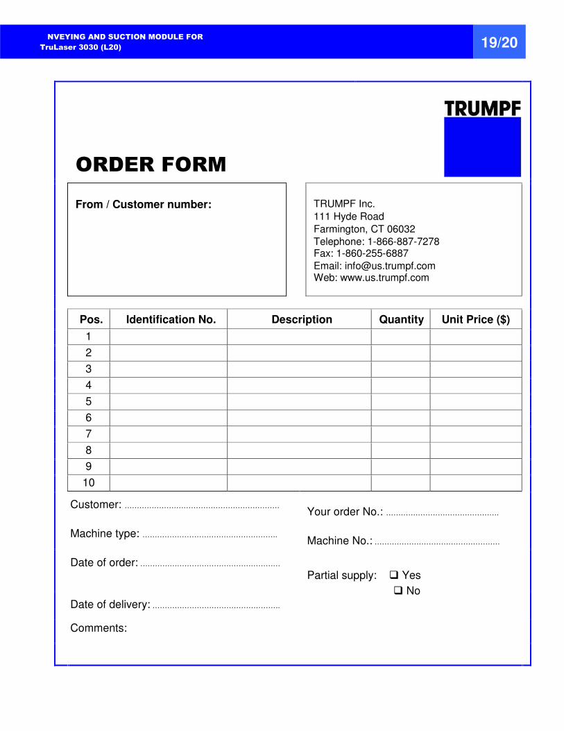
ORDER FORM
From / Customer number: TRUMPF Inc. 111 Hyde Road
Farmington, CT 06032
Telephone: 1-866-887-7278 Fax: 1-860-255-6887
Email: [email protected] Web: www.us.trumpf.com
Pos. Identification No. Description Quantity Unit Price ($)
1
2
3
4
5
6
7
8
9
10
Customer: ………………………………………………………
Your order No.: ……………………………………….
Machine type: ………………………………………………. Machine No.: ……………………………………………
Date of order: ………………………………………………… Partial supply: Yes
No
Date of delivery: …………………………………………….
Comments:

Hennig, Inc | 9900 N Alpine Rd, Rockford, IL 61115 | 815-636-9900 | www.hennig-inc.comData subject to change. CS-0914 Printed in USA Copyright © 2014
Innovative People, Products and Processes
At AME, innovation is part of our culture. You can see the resultin our processes, partnerships, people and services and in the precision engineered components, machines and servicesshowcased here. Learn more about AME and our innovative approach to precision machining, call 815-962-6076.
www.ame.com
Global Excellence in Machine Protection
For 50 years Hennig has been designing and producing custom machine protection and chip/coolant management products for state-of-the-art machine tools. Hennig products are reliable, durable, and perfectly tailored to protect against corrosion, debris and common workplace contaminants. There’s no better way to protect your investment on the shop floor.
www.hennigworldwide.com


![MACHINERY & PLANT LIST - KMF Group · Trumpf Trulaser 3030 L20 2011 Trumpf Trulaser 5030 L41 [Fibre] 2011 Trumpf Quicksharp 2011 ALL TRUMPF CHILLERS N/A Trumpf …](https://img.pdfslide.net/doc/110x75/5b7a8b9e7f8b9aad4c8c4fd2/machinery-plant-list-kmf-trumpf-trulaser-3030-l20-2011-trumpf-trulaser-5030.jpg)


![Pos. article: piece: price 1. LA-100 1 pc. EXW Laser ... · Type TruLaser 3030 - 4000W (L20) CNC Control Siemens Sinumerik 840 D SL Working area XxYxZ [mm] 3000x1500x115 Laser-Type:](https://img.pdfslide.net/doc/110x75/5b7a8b9e7f8b9aad4c8c4fb5/pos-article-piece-price-1-la-100-1-pc-exw-laser-type-trulaser-3030.jpg)