Embed Size (px)
Citation preview
www.swagelok.com
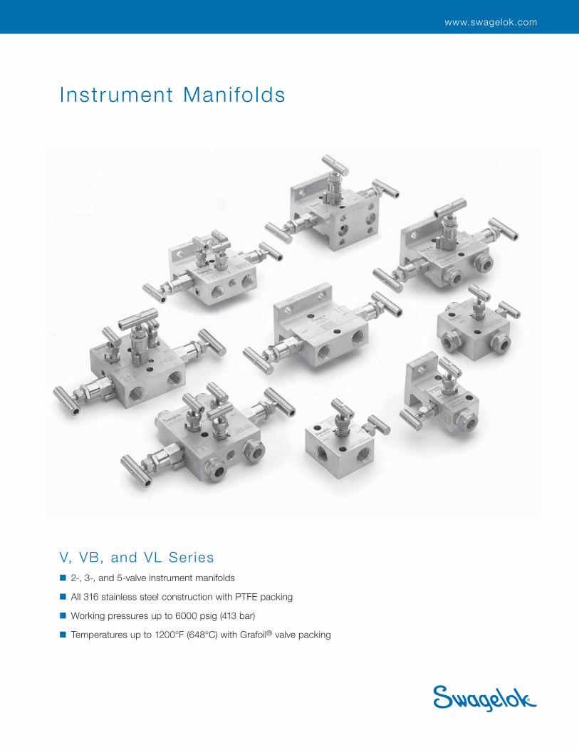
Instrument Mani fo lds
V, VB, and VL Ser ies
■ 2-, 3-, and 5-valve instrument manifolds
■ All 316 stainless steel construction with PTFE packing
■ Working pressures up to 6000 psig (413 bar)
■ Temperatures up to 1200°F (648°C) with Grafoil® valve packing
2 Instrument Manifolds—V, VB, and VL Series
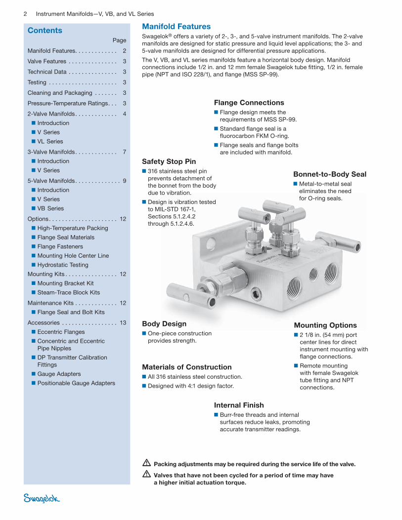
Manifold FeaturesSwagelok® offers a variety of 2-, 3-, and 5-valve instrument manifolds. The 2-valve
manifolds are designed for static pressure and liquid level applications; the 3- and
5-valve manifolds are designed for differential pressure applications.
The V, VB, and VL series manifolds feature a horizontal body design. Manifold
connections include 1/2 in. and 12 mm female Swagelok tube fi tting, 1/2 in. female
pipe (NPT and ISO 228/1), and fl ange (MSS SP-99).
Flange Connections
■ Flange design meets the
requirements of MSS SP-99.
■ Standard flange seal is a
fluorocarbon FKM O-ring.
■ Flange seals and flange bolts
are included with manifold.
Bonnet-to-Body Seal
■ Metal-to-metal seal
eliminates the need
for O-ring seals.
Mounting Options
■ 2 1/8 in. (54 mm) port
center lines for direct
instrument mounting with
fl ange connections.
■ Remote mounting
with female Swagelok
tube fi tting and NPT
connections.
Materials of Construction
■ All 316 stainless steel construction.
■ Designed with 4:1 design factor.
Body Design
■ One-piece construction
provides strength.
Internal Finish
■ Burr-free threads and internal
surfaces reduce leaks, promoting
accurate transmitter readings.
Safety Stop Pin
■ 316 stainless steel pin
prevents detachment of
the bonnet from the body
due to vibration.
■ Design is vibration tested
to MIL-STD 167-1,
Sections 5.1.2.4.2
through 5.1.2.4.6.
Contents Page
Manifold Features. . . . . . . . . . . . . 2
Valve Features . . . . . . . . . . . . . . . 3
Technical Data . . . . . . . . . . . . . . . 3
Testing . . . . . . . . . . . . . . . . . . . . . 3
Cleaning and Packaging . . . . . . . 3
Pressure-Temperature Ratings. . . 3
2-Valve Manifolds. . . . . . . . . . . . . 4
■ Introduction
■ V Series
■ VL Series
3-Valve Manifolds. . . . . . . . . . . . . 7
■ Introduction
■ V Series
5-Valve Manifolds. . . . . . . . . . . . . . 9
■ Introduction
■ V Series
■ VB Series
Options. . . . . . . . . . . . . . . . . . . . . 12
■ High-Temperature Packing
■ Flange Seal Materials
■ Flange Fasteners
■ Mounting Hole Center Line
■ Hydrostatic Testing
Mounting Kits . . . . . . . . . . . . . . . . 12
■ Mounting Bracket Kit
■ Steam-Trace Block Kits
Maintenance Kits . . . . . . . . . . . . . 12
■ Flange Seal and Bolt Kits
Accessories . . . . . . . . . . . . . . . . . 13
■ Eccentric Flanges
■ Concentric and Eccentric
Pipe Nipples
■ DP Transmitter Calibration
Fittings
■ Gauge Adapters
■ Positionable Gauge Adapters
� Packing adjustments may be required during the service life of the valve.
� Valves that have not been cycled for a period of time may have
a higher initial actuation torque.
Instrument Manifolds—V, VB, and VL Series 3
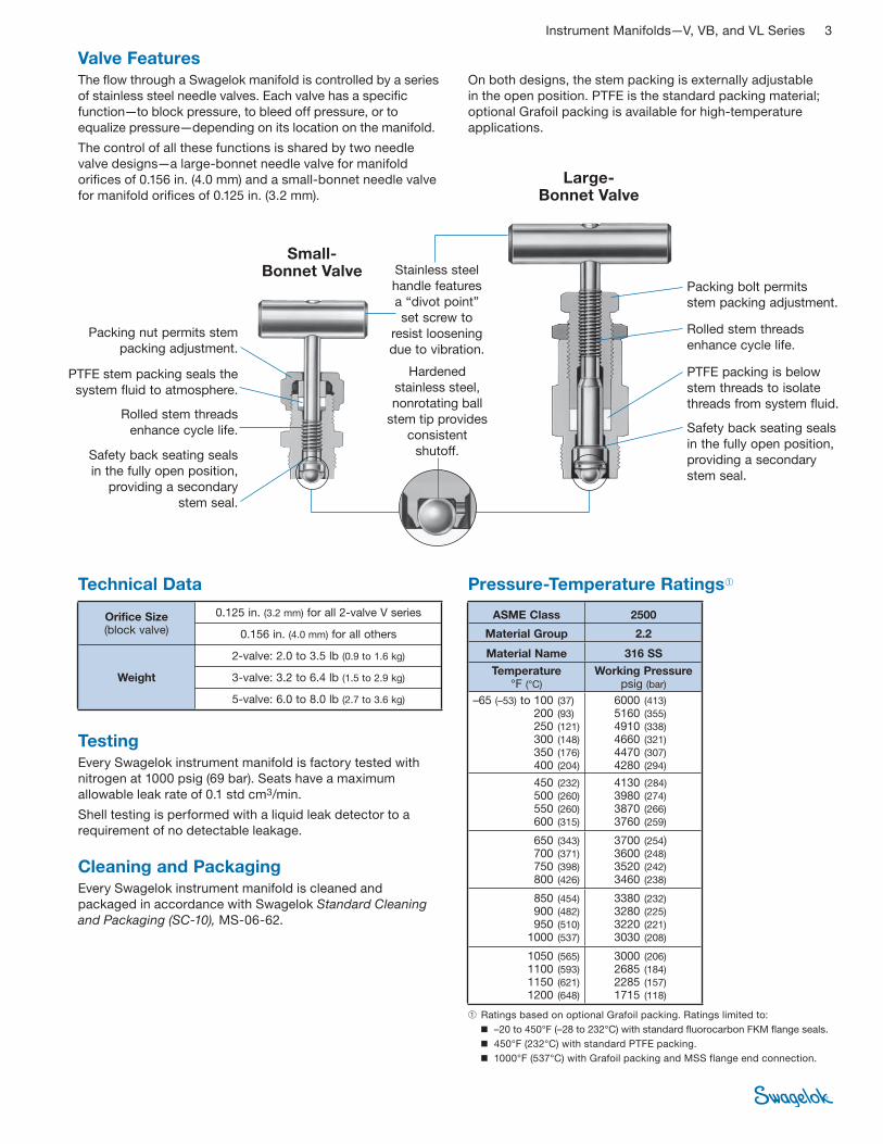
Valve FeaturesThe fl ow through a Swagelok manifold is controlled by a series
of stainless steel needle valves. Each valve has a specifi c
function—to block pressure, to bleed off pressure, or to
equalize pressure—depending on its location on the manifold.
The control of all these functions is shared by two needle
valve designs—a large-bonnet needle valve for manifold
orifi ces of 0.156 in. (4.0 mm) and a small-bonnet needle valve
for manifold orifi ces of 0.125 in. (3.2 mm).
Large- Bonnet Valve
Technical Data Pressure-Temperature Ratings➀
Packing bolt permits
stem packing adjustment.
Hardened
stainless steel,
nonrotating ball
stem tip provides
consistent
shutoff.
Rolled stem threads
enhance cycle life.
PTFE packing is below
stem threads to isolate
threads from system fluid.
Small- Bonnet Valve
Safety back seating seals
in the fully open position,
providing a secondary
stem seal.
➀ Ratings based on optional Grafoil packing. Ratings limited to:
■ –20 to 450°F (–28 to 232°C) with standard fluorocarbon FKM flange seals.
■ 450°F (232°C) with standard PTFE packing.
■ 1000°F (537°C) with Grafoil packing and MSS flange end connection.
On both designs, the stem packing is externally adjustable
in the open position. PTFE is the standard packing material;
optional Grafoil packing is available for high-temperature
applications.
Stainless steel
handle features
a “divot point”
set screw to
resist loosening
due to vibration.
Packing nut permits stem
packing adjustment.
Rolled stem threads
enhance cycle life.
PTFE stem packing seals the
system fluid to atmosphere.
Safety back seating seals
in the fully open position,
providing a secondary
stem seal.
TestingEvery Swagelok instrument manifold is factory tested with
nitrogen at 1000 psig (69 bar). Seats have a maximum
allowable leak rate of 0.1 std cm3/min.
Shell testing is performed with a liquid leak detector to a
require ment of no detectable leakage.
Cleaning and PackagingEvery Swagelok instrument manifold is cleaned and
packaged in accordance with Swagelok Standard Cleaning
and Packaging (SC-10), MS-06-62.
ASME Class 2500
Material Group 2.2
Material Name 316 SS
Temperature °F (°C)
Working Pressure psig (bar)
–65 (–53) to 100 (37) 200 (93) 250 (121) 300 (148) 350 (176)
400 (204)
6000 (413)
5160 (355) 4910 (338) 4660 (321)
4470 (307) 4280 (294)
450 (232) 500 (260) 550 (260) 600 (315)
4130 (284) 3980 (274) 3870 (266) 3760 (259)
650 (343) 700 (371) 750 (398) 800 (426)
3700 (254) 3600 (248) 3520 (242) 3460 (238)
850 (454) 900 (482) 950 (510) 1000 (537)
3380 (232) 3280 (225) 3220 (221) 3030 (208)
1050 (565) 1100 (593) 1150 (621) 1200 (648)
3000 (206) 2685 (184) 2285 (157) 1715 (118)
Orifice Size (block valve)
0.125 in. (3.2 mm) for all 2-valve V series
0.156 in. (4.0 mm) for all others
Weight
2-valve: 2.0 to 3.5 lb (0.9 to 1.6 kg)
3-valve: 3.2 to 6.4 lb (1.5 to 2.9 kg)
5-valve: 6.0 to 8.0 lb (2.7 to 3.6 kg)
4 Instrument Manifolds—V, VB, and VL Series
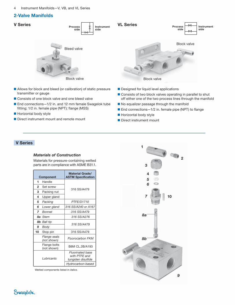
Materials of Construction
Materials for pressure-containing wetted
parts are in compliance with ASME B31.1.
2
4
5
6
7
8a
8b
9
Wetted components listed in italics.
1
3
10
2-Valve Manifolds
V Series VL Series
■ Designed for liquid level applications
■ Consists of two block valves operating in parallel to shut
off either one of the two process lines through the manifold
■ No equalizer passage through the manifold
■ End connections—1/2 in. female pipe (NPT) to flange
■ Horizontal body style
■ Direct instrument mount
■ Allows for block and bleed (or calibration) of static pressure
transmitter or gauge
■ Consists of one block valve and one bleed valve
■ End connections—1/2 in. and 12 mm female Swagelok tube
fitting; 1/2 in. female pipe (NPT); flange (MSS)
■ Horizontal body style
■ Direct instrument mount and remote mount
V Series
Block valve
Block valveBlock valve
Bleed valve
Instrument side
Process side
Instrument side
Process side
Component Material Grade/
ASTM Specification
1 Handle
316 SS/A479 2 Set screw
3 Packing nut
4 Upper gland
5 Packing PTFE/D1710
6 Lower gland 316 SS/A240 or A167
7 Bonnet 316 SS/A479
8a Stem 316 SS/A276
8b Ball tip 316 SS/A479
9 Body
10 Stop pin 316 SS/A479
Flange seals (not shown)
Fluorocarbon FKM
Flange bolts (not shown)
B8M CL.2B/A193
Lubricants
Fluorinated base with PTFE and
tungsten disulfide
Hydrocarbon-based
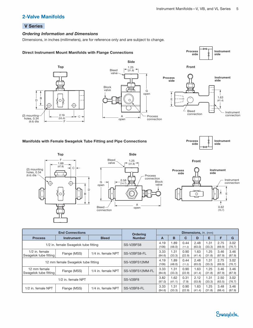
Instrument Manifolds—V, VB, and VL Series 5
Ordering Information and Dimensions
Dimensions, in inches (millimeters), are for reference only and are subject to change.
2-Valve Manifolds
Direct Instrument Mount Manifolds with Flange Connections
Manifolds with Female Swagelok Tube Fitting and Pipe Connections
(2) mounting holes, 0.34
(8.6) dia
Block valve
FrontBleed valve
Side
1.63 (41.4)
2.19 (55.6)
A open
Top
C
B ED
F
G open
1.25 (31.8)
Instrument side
Process side
Bleed connection
Instrument connectionProcess
connection
V Series
Instrument side
Process side
Top
B
Bleed valve
Front
Side
Block valve
1.25 (31.8)
F
C
D
E
1.88 (47.8)
Bleed connection
Process connection
Instrument connection
A open
G open
0.58 (14.7)
0.62 (15.7)
Instrument side
Process side
(2) mounting holes, 0.34 (8.6) dia
Instrument side
Process side
End Connections Ordering Number
Dimensions, in. (mm)
Process Instrument Bleed A B C D E F G
1/2 in. female Swagelok tube fitting SS-V2BFS8 4.19 (106)
1.89 (48.0)
0.44 (11.2)
2.48 (63.0)
1.31 (33.3)
2.75 (69.9)
3.02 (76.7)
1/2 in. female Swagelok tube fitting
Flange (MSS) 1/4 in. female NPT SS-V2BFS8-FL 3.33 (84.6)
1.31 (33.3)
0.90 (22.9)
1.63 (41.4)
1.25 (31.8)
3.46 (87.9)
3.46 (87.9)
12 mm female Swagelok tube fitting SS-V2BFS12MM 4.19 (106)
1.89 (48.0)
0.44 (11.2)
2.48 (63.0)
1.31 (33.3)
2.75 (69.9)
3.02 (76.7)
12 mm female Swagelok tube fitting
Flange (MSS) 1/4 in. female NPT SS-V2BFS12MM-FL 3.33 (84.6)
1.31 (33.3)
0.90 (22.9)
1.63 (41.4)
1.25 (31.8)
3.46 (87.9)
3.46 (87.9)
1/2 in. female NPT SS-V2BF8 3.82 (97.0)
1.62 (41.1)
0.31 (7.9)
2.12 (53.8)
1.31 (33.3)
2.50 (63.5)
3.02 (76.7)
1/2 in. female NPT Flange (MSS) 1/4 in. female NPT SS-V2BF8-FL 3.33 (84.6)
1.31 (33.3)
0.90 (22.9)
1.63 (41.4)
1.25 (31.8)
3.48 (88.4)
3.46 (87.9)
6 Instrument Manifolds—V, VB, and VL Series
2
45
6
7a
7b
9 1
3
8
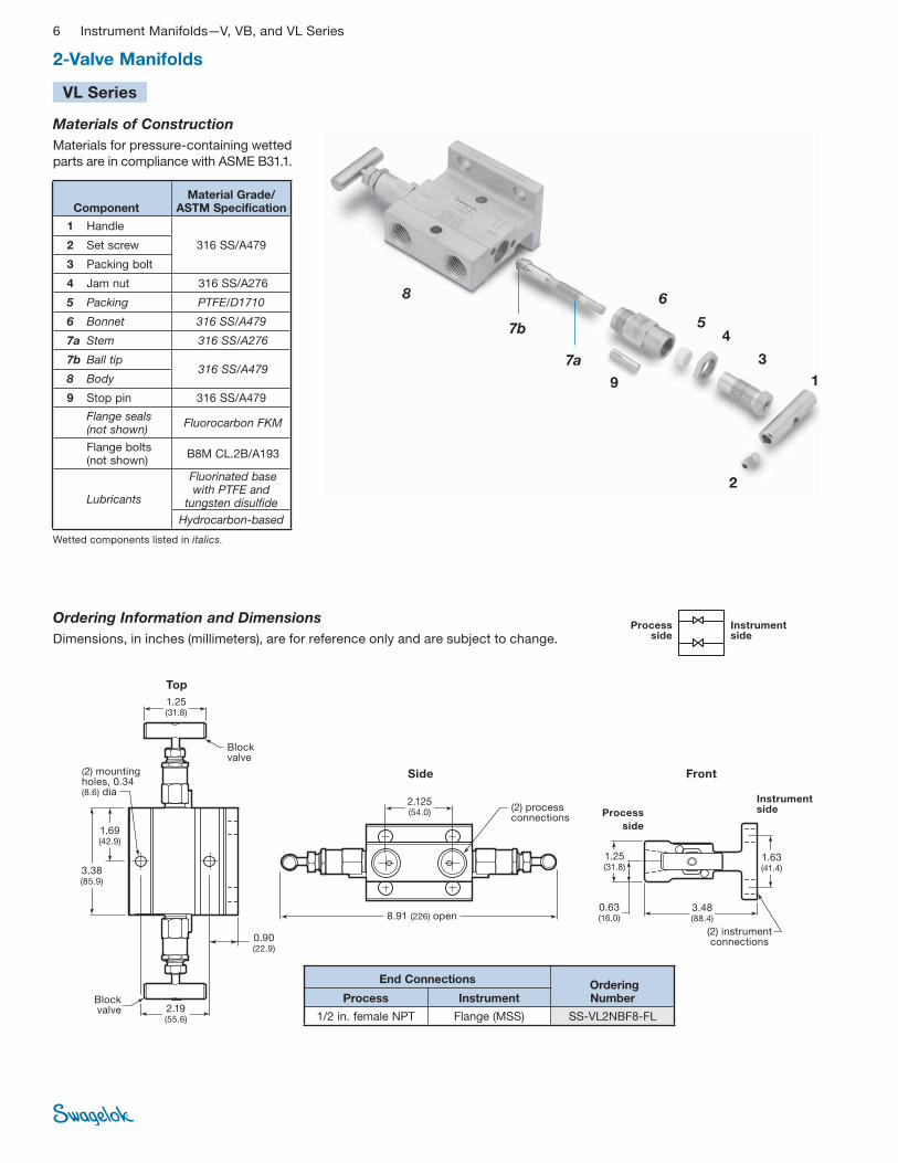
2-Valve Manifolds
VL Series
Wetted components listed in italics.
Materials of Construction
Materials for pressure-containing wetted
parts are in compliance with ASME B31.1.
Ordering Information and Dimensions
Dimensions, in inches (millimeters), are for reference only and are subject to change.Instrument side
Process side
Block valve
Side
Instrument side
Top
Block valve
(2) mounting holes, 0.34 (8.6) dia
1.63(41.4)
1.25 (31.8)
2.19 (55.6)
Process
side
Front
(2) process connections
3.38 (85.9)
1.69 (42.9)
0.90 (22.9)
8.91 (226) open
1.25 (31.8)
0.63 (16.0)
3.48 (88.4)
2.125 (54.0)
(2) instrument connections
Component Material Grade/
ASTM Specification
1 Handle
316 SS/A479 2 Set screw
3 Packing bolt
4 Jam nut 316 SS/A276
5 Packing PTFE/D1710
6 Bonnet 316 SS/A479
7a Stem 316 SS/A276
7b Ball tip 316 SS/A479
8 Body
9 Stop pin 316 SS/A479
Flange seals (not shown)
Fluorocarbon FKM
Flange bolts (not shown)
B8M CL.2B/A193
Lubricants
Fluorinated base with PTFE and
tungsten disulfide
Hydrocarbon-based
End Connections Ordering Number Process Instrument
1/2 in. female NPT Flange (MSS) SS-VL2NBF8-FL
Instrument Manifolds—V, VB, and VL Series 7
2
4
5
6
7a
7b
8
1
3
9
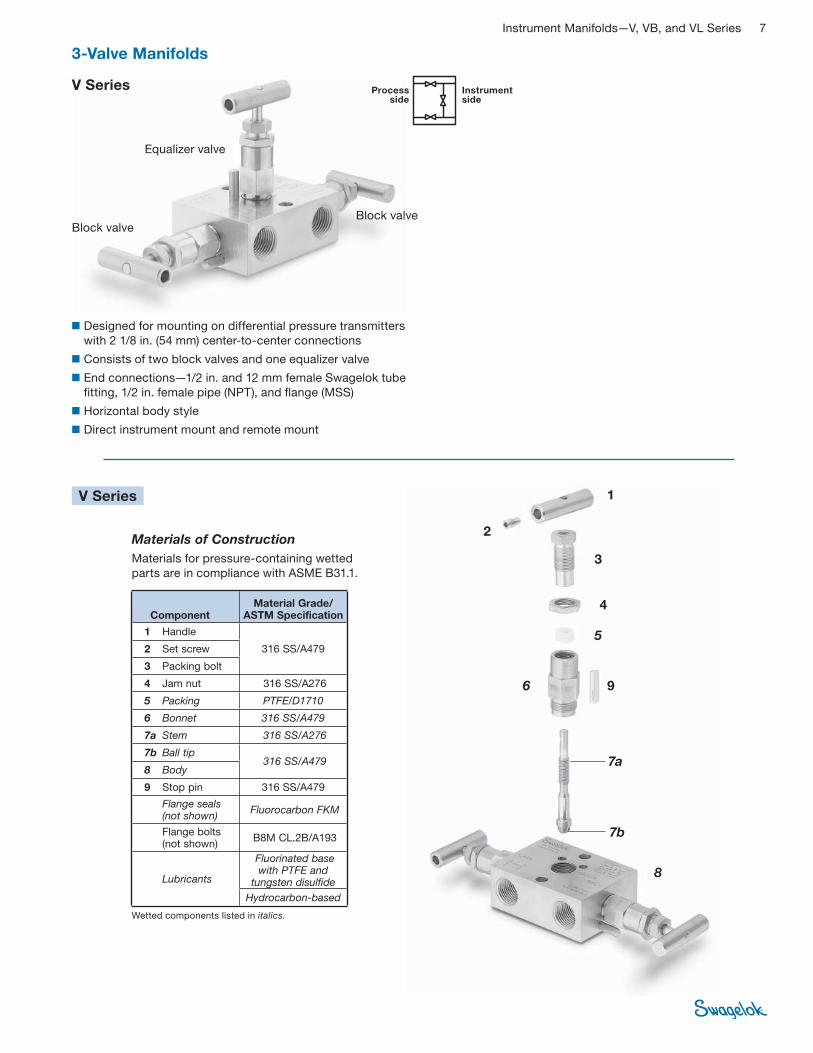
3-Valve Manifolds
■ Designed for mounting on differential pressure transmitters
with 2 1/8 in. (54 mm) center-to-center connections
■ Consists of two block valves and one equalizer valve
■ End connections—1/2 in. and 12 mm female Swagelok tube
fi tting, 1/2 in. female pipe (NPT), and fl ange (MSS)
■ Horizontal body style
■ Direct instrument mount and remote mount
V Series
Block valveBlock valve
Equalizer valve
V Series
Wetted components listed in italics.
Materials of Construction
Materials for pressure-containing wetted
parts are in compliance with ASME B31.1.
Instrument side
Process side
Component Material Grade/
ASTM Specification
1 Handle
316 SS/A479 2 Set screw
3 Packing bolt
4 Jam nut 316 SS/A276
5 Packing PTFE/D1710
6 Bonnet 316 SS/A479
7a Stem 316 SS/A276
7b Ball tip 316 SS/A479
8 Body
9 Stop pin 316 SS/A479
Flange seals (not shown)
Fluorocarbon FKM
Flange bolts (not shown)
B8M CL.2B/A193
Lubricants
Fluorinated base with PTFE and
tungsten disulfide
Hydrocarbon-based
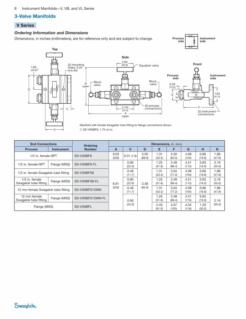
8 Instrument Manifolds—V, VB, and VL Series
3-Valve Manifolds
V Series
Instrument side
Process side
(2) mounting holes, 0.34 (8.6) dia
Top
Side
2.00 (50.8)
E
C
Block valve
Process side
Instrument side
Block valve
Equalizer valve Front
1.63 (41.4)H
(2) process connections
Manifold with female Swagelok tube fitting-to-flange connections shown.
➀ SS-V3NBF8: 1.75 (44.4).
(2) instrument connections
0.59 (15.0)
1.60(42.9)➀
K
G open
2.125(54.0)
A open
D
F
Ordering Information and Dimensions
Dimensions, in inches (millimeters), are for reference only and are subject to change.
End Connections Ordering Number
Dimensions, in. (mm)
Process Instrument A C D E F G H K
1/2 in. female NPT SS-V3NBF8 9.03 (229)
0.31 (7.9) 3.50 (88.9)
1.31 (33.3)
2.50 (63.5)
4.08 (104)
0.66 (16.8)
1.88 (47.8)
1/2 in. female NPT Flange (MSS) SS-V3NBF8-FL
8.91 (226)
0.90 (22.9)
3.38 (85.9)
1.25 (31.8)
3.48 (88.4)
4.51 (115)
0.63 (16.0)
2.19 (55.6)
1/2 in. female Swagelok tube fitting SS-V3NBFS8 0.46 (11.7)
1.31 (33.3)
3.04 (77.2)
4.08 (104)
0.66 (16.8)
1.88 (47.8)
1/2 in. female Swagelok tube fitting
Flange (MSS) SS-V3NBFS8-FL 0.90 (22.9)
1.25 (31.8)
3.48 (88.4)
4.51 (115)
0.63 (16.0)
2.19 (55.6)
12 mm female Swagelok tube fitting SS-V3NBFS12MM 0.46 (11.7)
1.31 (33.3)
3.04 (77.2)
4.08 (104)
0.66 (16.8)
1.88 (47.8)
12 mm female Swagelok tube fitting
Flange (MSS) SS-V3NBFS12MM-FL 0.90 (22.9)
1.25 (31.8)
3.48 (88.4)
4.51 (115)
0.63 (16.0) 2.19
(55.6) Flange (MSS) SS-V3NBFL
2.40 (61.0)
4.07 (103)
4.55 (116)
1.20 (30.5)
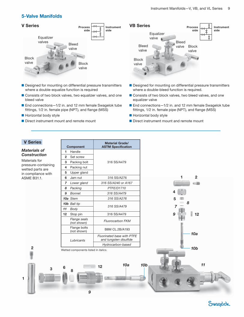
Instrument Manifolds—V, VB, and VL Series 9
5-Valve Manifolds
V Series VB Series
■ Designed for mounting on differential pressure transmitters
where a double-equalize function is required
■ Consists of two block valves, two equalizer valves, and one
bleed valve
■ End connections—1/2 in. and 12 mm female Swagelok tube
fittings, 1/2 in. female pipe (NPT), and flange (MSS)
■ Horizontal body style
■ Direct instrument mount and remote mount
■ Designed for mounting on differential pressure transmitters
where a double-bleed function is required.
■ Consists of two block valves, two bleed valves, and one
equalizer valve
■ End connections—1/2 in. and 12 mm female Swagelok tube
fittings, 1/2 in. female pipe (NPT), and flange (MSS)
■ Horizontal body style
■ Direct instrument mount and remote mount
2
4
5
86
7
10b
8
1
3
9
Materials of Construction
Materials for
pressure-containing
wetted parts are
in compliance with
ASME B31.1.
V Series
10a
11
9
10b10a
12
2
1
12
Block
valve
Equalizer
valves
Equalizer
valveBleed
valveBleed
valve
Bleed
valveBlock
valve
Block
valveBlock
valve
Wetted components listed in italics.
Instrument side
Processside
Instrument side
Processside
Component Material Grade/
ASTM Specification
1 Handle
316 SS/A479
2 Set screw
3 Packing bolt
4 Packing nut
5 Upper gland
6 Jam nut 316 SS/A276
7 Lower gland 316 SS/A240 or A167
8 Packing PTFE/D1710
9 Bonnet 316 SS/A479
10a Stem 316 SS/A276
10b Ball tip 316 SS/A479
11 Body
12 Stop pin 316 SS/A479
Flange seals (not shown)
Fluorocarbon FKM
Flange bolts (not shown)
B8M CL.2B/A193
Lubricants
Fluorinated base with PTFE and tungsten disulfide
Hydrocarbon-based
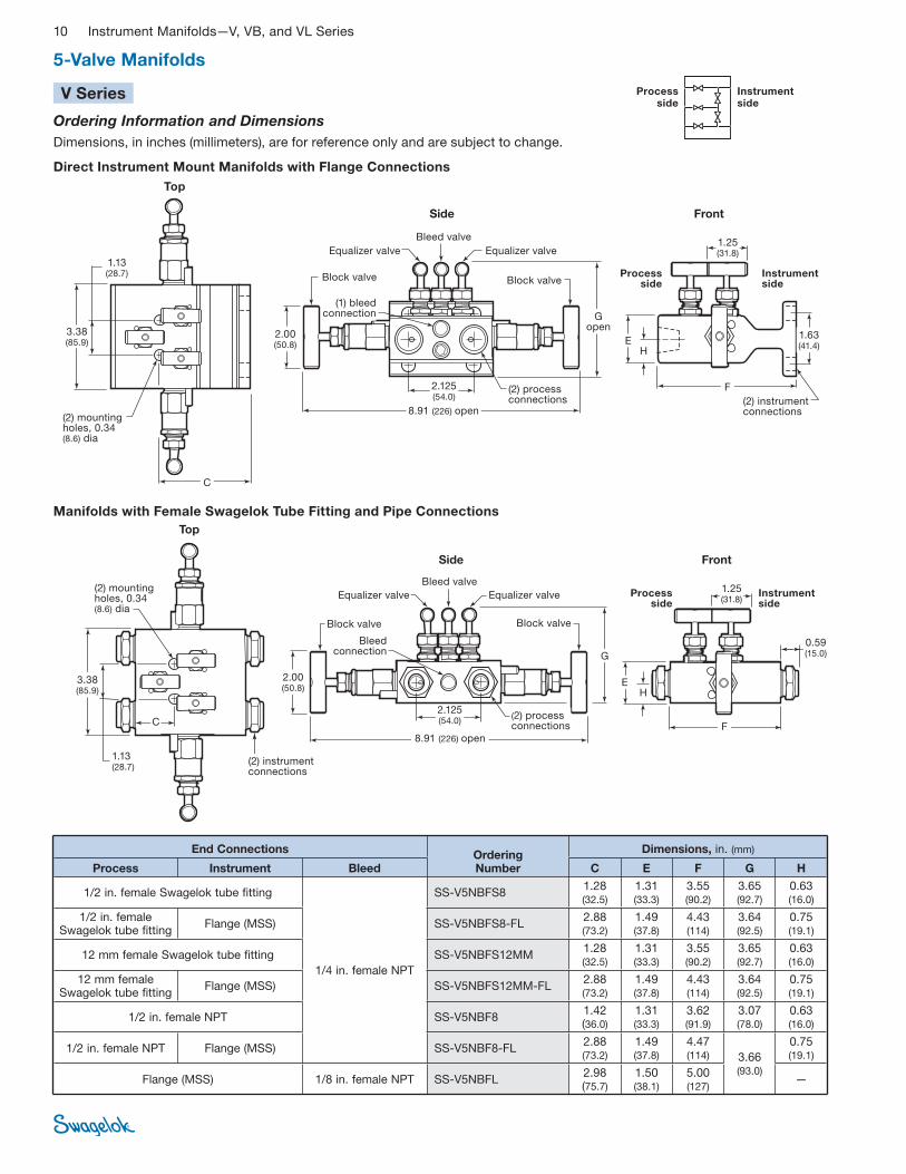
10 Instrument Manifolds—V, VB, and VL Series
(2) mounting holes, 0.34 (8.6) dia
Top
Side
2.00 (50.8) E
1.13 (28.7)
C
Block valve Block valve
Equalizer valve
Front
1.63 (41.4)
F2.125 (54.0)
1.25(31.8)Equalizer valve
Bleed valve
(1) bleed connection
(2) process connections
G open
H
Direct Instrument Mount Manifolds with Flange Connections
(2) instrument connections
Manifolds with Female Swagelok Tube Fitting and Pipe Connections
8.91 (226) open
3.38 (85.9)
Instrument side
Processside
Process side
Instrument side
Top
Side Front
1.25 (31.8)
E
F
H
(2) mounting holes, 0.34 (8.6) dia
1.13 (28.7)
2.00 (50.8)
Block valveBlock valve
Equalizer valve Equalizer valve
Bleed valve
Bleed connection
(2) process connections
G
C
(2) instrument connections
0.59 (15.0)
8.91 (226) open
3.38 (85.9)
2.125 (54.0)
Process side
Instrument side
5-Valve Manifolds
V Series
Ordering Information and Dimensions
Dimensions, in inches (millimeters), are for reference only and are subject to change.
End Connections Ordering Number
Dimensions, in. (mm)
Process Instrument Bleed C E F G H
1/2 in. female Swagelok tube fitting
1/4 in. female NPT
SS-V5NBFS8 1.28 (32.5)
1.31 (33.3)
3.55 (90.2)
3.65 (92.7)
0.63 (16.0)
1/2 in. female Swagelok tube fitting
Flange (MSS) SS-V5NBFS8-FL 2.88 (73.2)
1.49 (37.8)
4.43 (114)
3.64 (92.5)
0.75 (19.1)
12 mm female Swagelok tube fitting SS-V5NBFS12MM 1.28 (32.5)
1.31 (33.3)
3.55 (90.2)
3.65 (92.7)
0.63 (16.0)
12 mm female Swagelok tube fitting
Flange (MSS) SS-V5NBFS12MM-FL 2.88 (73.2)
1.49 (37.8)
4.43 (114)
3.64 (92.5)
0.75 (19.1)
1/2 in. female NPT SS-V5NBF8 1.42 (36.0)
1.31 (33.3)
3.62 (91.9)
3.07 (78.0)
0.63 (16.0)
1/2 in. female NPT Flange (MSS) SS-V5NBF8-FL 2.88 (73.2)
1.49 (37.8)
4.47 (114) 3.66
(93.0)
0.75 (19.1)
Flange (MSS) 1/8 in. female NPT SS-V5NBFL 2.98 (75.7)
1.50 (38.1)
5.00 (127)
—
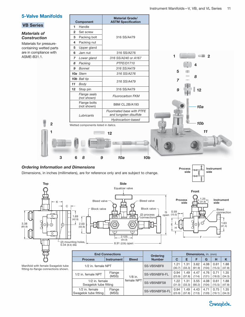
Instrument Manifolds—V, VB, and VL Series 11
2
4
5
86
7
10b
8
1
3
9
10a
11
9 10b10a
12
2
1
5-Valve Manifolds
Manifold with female Swagelok tube fitting-to-flange connections shown.
12
Wetted components listed in italics.
Ordering Information and Dimensions
Dimensions, in inches (millimeters), are for reference only and are subject to change.
VB Series
Materials of Construction
Materials for pressure-
containing wetted parts
are in compliance with
ASME-B31.1.
Instrument side
Processside
Top Side
Front
1.25 (31.8)
E
F
H
(2) mounting holes, 0.34 (8.6) dia
1.69 (42.9)
2.00 (50.8)
Block valveBlock valve
Equalizer valve
Bleed valve
Bleed connection
(2) process connections
G open
C
K
1.63 (41.4)
Bleed valve
3.38 (85.9)
0.59 (15.0)
8.91 (226) open
2.125 (54.0)
Process side
Instrument side
Component Material Grade/
ASTM Specification
1 Handle
316 SS/A479
2 Set screw
3 Packing bolt
4 Packing nut
5 Upper gland
6 Jam nut 316 SS/A276
7 Lower gland 316 SS/A240 or A167
8 Packing PTFE/D1710
9 Bonnet 316 SS/A479
10a Stem 316 SS/A276
10b Ball tip 316 SS/A479
11 Body
12 Stop pin 316 SS/A479
Flange seals (not shown)
Fluorocarbon FKM
Flange bolts (not shown)
B8M CL.2B/A193
Lubricants
Fluorinated base with PTFE and tungsten disulfide
Hydrocarbon-based
End Connections Ordering Number
Dimensions, in. (mm)
Process Instrument Bleed C E F G H K
1/2 in. female NPT
1/8 in. female NPT
SS-VB5NBF8 1.21 (30.7)
1.31 (33.3)
3.62 (91.9)
4.08 (104)
0.61 (15.5)
1.88 (47.8)
1/2 in. female NPT Flange (MSS)
SS-VB5NBF8-FL 0.94 (23.9)
1.49 (37.8)
4.47 (114)
4.76 (121)
0.71 (18.0)
1.35 (34.3)
1/2 in. female Swagelok tube fitting
SS-VB5NBFS8 1.22 (31.0)
1.31 (33.3)
3.55 (90.2)
4.08 (104)
0.61 (15.5)
1.88 (47.8)
1/2 in. female Swagelok tube fitting
Flange (MSS)
SS-VB5NBFS8-FL 0.94 (23.9)
1.49 (37.8)
4.43 (113)
4.71 (120)
0.75 (19.1)
1.35 (34.3)
12 Instrument Manifolds—V, VB, and VL Series
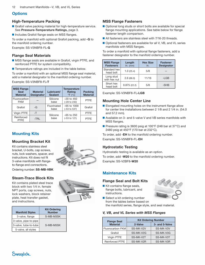
MSS Flange Fasteners
■ Optional long studs or short bolts are available for special
fl ange mounting applications. See table below for fl ange
fastener length comparison.
■ All fasteners are stainless steel with 7/16-20 threads.
■ Optional fasteners are available for all V, VB, and VL series
manifolds with MSS fl anges.
To order a manifold with optional fl ange fasteners, add a
fastener designator to the manifold ordering number.
Example: SS-V3NBF8-FL-LGB
Mounting Hole Center Line
■ Elongated mounting holes on the instrument flange allow
for center line installations between 2 1/8 and 2 1/4 in. (54.0
and 57.2 mm).
■ Available on 3- and 5-valve V and VB series manifolds with
MSS fl anges.
■ Pressure rating is 3600 psig at 100°F (248 bar at 37°C) and
2480 psig at 450°F (170 bar at 232°C).
To order, add -EH to the manifold ordering number.
Example: SS-V5NBF8-FL-EH
Hydrostatic Testing
Hydrostatic testing is available as an option.
To order, add -W20 to the manifold ordering number.
Example: SS-V2BF8-W20
MSS Flange Fasteners
Length in. (mm)
Hex Size in.
Fastener Designator
Standard hex head bolt
1.0 (25.4) 5/8 —
Long stud with hex nut
2.6 (66.0) 11/16 -LGB
Short hex head bolt
0.875 (22.2) 5/8 -SHB
Flange Seal and Bolt Kits
■ Kit contains fl ange seals,
fl ange bolts, lubricant, and
instructions.
■ Select a kit ordering number
from the tables below based on
the manifold series, fl ange style, and seal material.
Mounting Bracket Kit
Kit contains stainless steel
bracket, U-bolts, cap screws,
nuts, lock washers, spacer, and
instructions. Kit does not fi t
3-valve manifolds with fl ange-
to-fl ange end connections.
Ordering number: SS-MB-VBK
Steam-Trace Block Kits
Kit contains plated steel trace
block with two 1/4 in. female
NPT ports, cap screws, nuts,
lock washers, block retainer
plate, heat transfer gasket,
and instructions.
Mounting Kits
Maintenance Kits
V, VB, and VL Series with MSS Flanges
High-Temperature Packing
■ Grafoil valve packing material for high-temperature service.
See Pressure-Temperature Ratings, page 3.
■ Includes Grafoil flange seals on MSS flanges.
To order a manifold with optional Grafoil packing, add -G to
the manifold ordering number.
Example: SS-V3NBF8-FL-G
Flange Seal Materials
■ MSS flange seals are available in Grafoil, virgin PTFE, and
reinforced PTFE for system compatibility.
■ Temperature ratings are included in the table below.
To order a manifold with an optional MSS fl ange seal material,
add a material designator to the manifold ordering number.
Example: SS-V3NBF8-FL-T
Options
MSS Flange Seal
Material Material
Designator Lubricant/
Sealant
Temperature Rating °F (°C)
Packing Material
Fluorocarbon FKM
— Silicone
base –20 to 450 (–28 to 232)
PTFE
Grafoil -G Fluorinated
base –65 to 1000 (–53 to 537)
Grafoil
Virgin PTFE -T Silicone
base –65 to 250 (–53 to 121)
PTFE
Reinforced PTFE
-TRL PTFE
Flange Seal Material
Kit Ordering Number
2-Valve 3- and 5-Valve
Fluorocarbon FKM SS-MK-V2V SS-MK-V3V
Grafoil SS-MK-V2G SS-MK-V3G
Virgin PTFE SS-MK-V2T SS-MK-V3T
Reinforced PTFE SS-MK-V2R SS-MK-V3R
Manifold StylesKit Ordering
Number
3-valve, flange S-MB-M3SK
3-valve, pipe-to-pipe
S-MB-M5SK3-valve, tube-to-tube
5-valve, all styles
Instrument Manifolds—V, VB, and VL Series 13
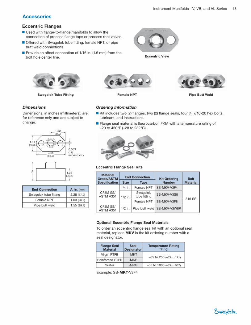
Ordering Information
■ Kit includes two (2) flanges, two (2) flange seals, four (4) 7/16-20 hex bolts,
lubricant, and instructions.
■ Flange seal material is fl uorocarbon FKM with a temperature rating of
–20 to 450°F (–28 to 232°C).
Accessories
Dimensions
Dimensions, in inches (millimeters), are
for reference only and are subject to
change.
Optional Eccentric Flange Seal Materials
To order an eccentric fl ange seal kit with an optional seal
material, replace MKV in the kit ordering number with a
seal designator.
Eccentric Flange Seal Kits
Female NPT Pipe Butt WeldSwagelok Tube Fitting
A
0.063 (1.6)eccentricity
1.03 (26.2)
1.22 (31.0)
1.31 (33.3)
2.45 (62.2)
Eccentric View
Eccentric Flanges
■ Used with flange-to-flange manifolds to allow the
connection of process flange taps or process root valves.
■ Offered with Swagelok tube fi tting, female NPT, or pipe
butt weld connections.
■ Provide an offset connection of 1/16 in. (1.6 mm) from the
bolt hole center line.
Example: SS-MKT-V3F4
End Connection A, in. (mm)
Swagelok tube fitting 2.25 (57.2)
Female NPT 1.03 (26.2)
Pipe butt weld 1.55 (39.4)
Material Grade/ASTM Specification
End Connection Kit Ordering
Number Bolt
Material Size Type
CF8M SS/ ASTM A351
1/4 in. Female NPT SS-MKV-V3F4
316 SS 1/2 in.
Swagelok tube fitting
SS-MKV-V3S8
Female NPT SS-MKV-V3F8
CF3M SS/ ASTM A351
1/2 in. Pipe butt weld SS-MKV-V3W8P
Flange Seal Material
Seal Designator
Temperature Rating °F (°C)
Virgin PTFE -MKT –65 to 250 (–53 to 121)
Reinforced PTFE -MKR
Grafoil -MKG –65 to 1000 (–53 to 537)
14 Instrument Manifolds—V, VB, and VL Series
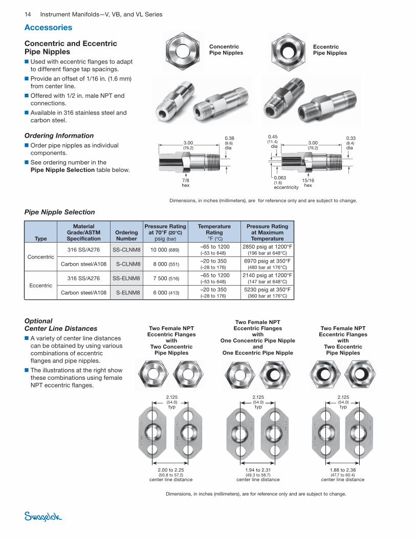
Concentric and Eccentric Pipe Nipples
■ Used with eccentric flanges to adapt
to different flange tap spacings.
■ Provide an offset of 1/16 in. (1.6 mm)
from center line.
■ Offered with 1/2 in. male NPT end
connections.
■ Available in 316 stainless steel and
carbon steel.
Ordering Information
■ Order pipe nipples as individual
components.
■ See ordering number in the
Pipe Nipple Selection table below.
Concentric Pipe Nipples
Eccentric Pipe Nipples
Pipe Nipple Selection
OptionalCenter Line Distances
■ A variety of center line distances
can be obtained by using various
combinations of eccentric
flanges and pipe nipples.
■ The illustrations at the right show
these combinations using female
NPT eccentric fl anges.
Accessories
Two Female NPTEccentric Flanges
with Two Concentric
Pipe Nipples
Two Female NPT Eccentric Flanges
with Two Eccentric Pipe Nipples
Two Female NPT Eccentric Flanges
with One Concentric Pipe Nipple
and One Eccentric Pipe Nipple
2.125 (54.0)typ
2.00 to 2.25(50.8 to 57.2)
center line distance
1.88 to 2.38(47.7 to 60.4)
center line distance
1.94 to 2.31(49.3 to 58.7)
center line distance
3.00 (76.2)
0.38 (9.6) dia
0.063(1.6) eccentricity
0.45 (11.4)
dia
0.33 (8.4) dia
7/8 hex
15/16 hex
Dimensions, in inches (millimeters), are for reference only and are subject to change.
Dimensions, in inches (millimeters), are for reference only and are subject to change.
2.125 (54.0)typ
Type
Material Grade/ASTM Specification
Ordering Number
Pressure Rating at 70°F (20°C)
psig (bar)
Temperature Rating °F (°C)
Pressure Rating at Maximum Temperature
Concentric
316 SS/A276 SS-CLNM8 10 000 (689) –65 to 1200 (–53 to 648)
2850 psig at 1200°F (196 bar at 648°C)
Carbon steel/A108 S-CLNM8 8 000 (551) –20 to 350 (–28 to 176)
6970 psig at 350°F (480 bar at 176°C)
Eccentric
316 SS/A276 SS-ELNM8 7 500 (516) –65 to 1200 (–53 to 648)
2140 psig at 1200°F (147 bar at 648°C)
Carbon steel/A108 S-ELNM8 6 000 (413) –20 to 350 (–28 to 176)
5230 psig at 350°F (360 bar at 176°C)
2.125 (54.0)typ
3.00 (76.2)
Instrument Manifolds—V, VB, and VL Series 15
Additional Manifold ProductsFor direct-mount
manifolds, see the
Swagelok Direct-
Mount Manifolds—
VE Series catalog,
MS-02-308.
For remote-mount
manifolds, see the
Swagelok Remote-
Mount Manifold—
Two Valve catalog,
MS-02-330.
For bellows-sealed
3-valve manifolds,
see the Swagelok
Bellows-Sealed
3-Valve Manifolds—
V3 Series catalog,
MS-02-07. The
manifolds use B or
U series bellows-sealed valves for systems with diffi cult fl uid
containment requirements.
Gauge Adapters
■ Adapt female BSP/ISO parallel thread
to male NPT threads.
■ Are offered in 1/4, 3/8, and 1/2 in.
male NPT sizes.
■ Are available in 316 stainless steel
material.
For more information, see the Swagelok Pipe Fittings catalog,
MS-01-147.
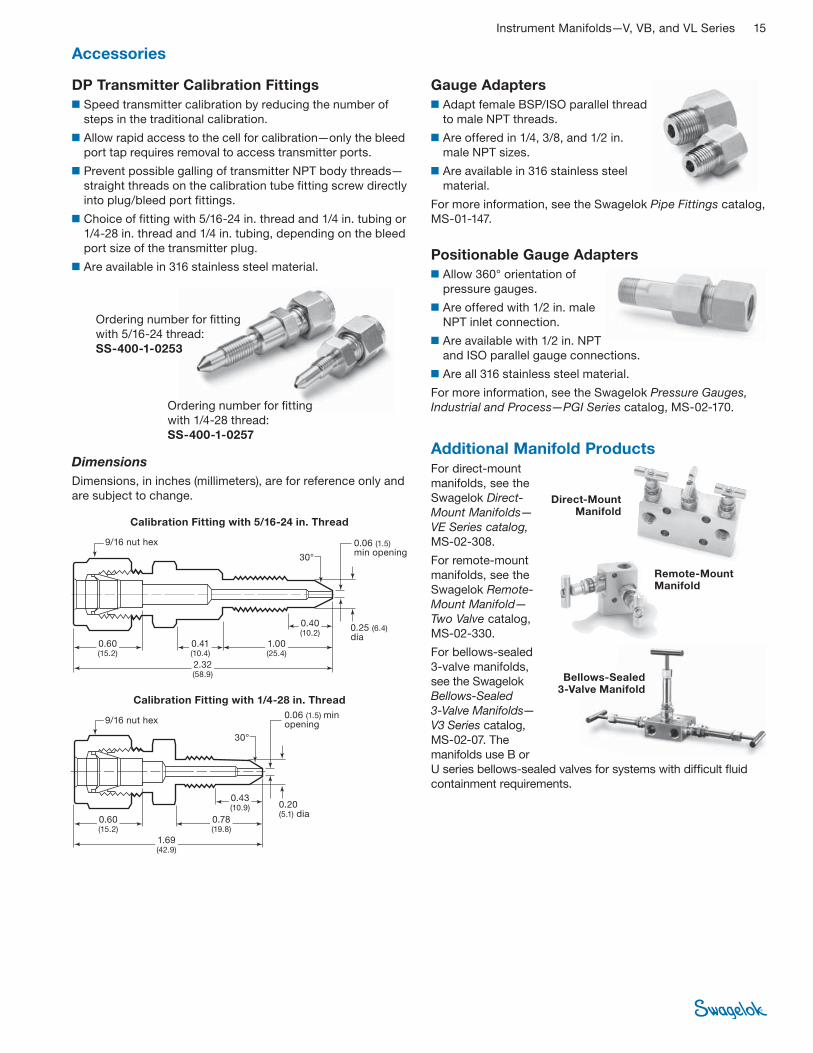
DP Transmitter Calibration Fittings
■ Speed transmitter calibration by reducing the number of
steps in the traditional calibration.
■ Allow rapid access to the cell for calibration—only the bleed
port tap requires removal to access transmitter ports.
■ Prevent possible galling of transmitter NPT body threads—
straight threads on the calibration tube fitting screw directly
into plug/bleed port fittings.
■ Choice of fitting with 5/16-24 in. thread and 1/4 in. tubing or
1/4-28 in. thread and 1/4 in. tubing, depending on the bleed
port size of the transmitter plug.
■ Are available in 316 stainless steel material.
Ordering number for fi tting
with 1/4-28 thread:
SS-400-1-0257
Ordering number for fi tting
with 5/16-24 thread:
SS-400-1-0253
Accessories
Dimensions
Dimensions, in inches (millimeters), are for reference only and
are subject to change.
0.60 (15.2)
0.41 (10.4)
2.32 (58.9)
1.00 (25.4)
0.25 (6.4) dia
9/16 nut hex
30°
0.06 (1.5) min opening
0.40 (10.2)
Calibration Fitting with 5/16-24 in. Thread
Calibration Fitting with 1/4-28 in. Thread
0.60 (15.2)
0.78 (19.8)
1.69 (42.9)
0.20 (5.1) dia
30°
0.06 (1.5) min opening
0.43 (10.9)
9/16 nut hex
Positionable Gauge Adapters
■ Allow 360° orientation of
pressure gauges.
■ Are offered with 1/2 in. male
NPT inlet connection.
■ Are available with 1/2 in. NPT
and ISO parallel gauge connections.
■ Are all 316 stainless steel material.
For more information, see the Swagelok Pressure Gauges,
Industrial and Process—PGI Series catalog, MS-02-170.
Direct-Mount Manifold
Remote-Mount Manifold
Bellows-Sealed 3-Valve Manifold

Safe Product Selection
When selecting a product, the total system design must
be considered to ensure safe, trouble-free performance.
Function, material compatibility, adequate ratings,
proper installation, operation, and maintenance are the
responsibilities of the system designer and user.
Caution: Do not mix or interchange parts with those of
other manufacturers.
Warranty InformationSwagelok products are backed by The Swagelok Limited
Lifetime Warranty. For a copy, visit swagelok.com or contact
your authorized Swagelok representative.
Swagelok—TM Swagelok CompanyGrafoil—TM UCAR Carbon Company Inc.© 2002, 2005, 2007 Swagelok CompanyPrinted in U.S.A., MIJune 2007, R4MS-01-178