Embed Size (px)
Citation preview
INSULATED CROSS-ARM AND
WORLDWIDE EXPERIENCE OF COMPACT LINES
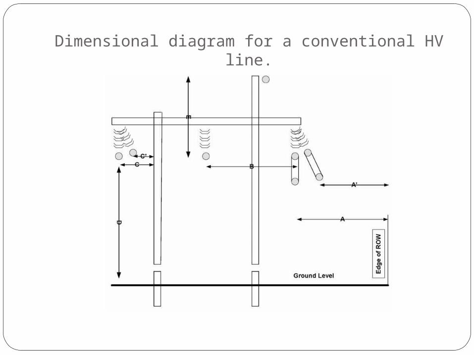
Dimensional diagram for a conventional HV line.
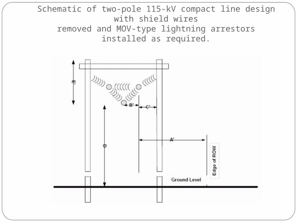
Schematic of two-pole 115-kV compact line design with shield wires
removed and MOV-type lightning arrestors installed as required.
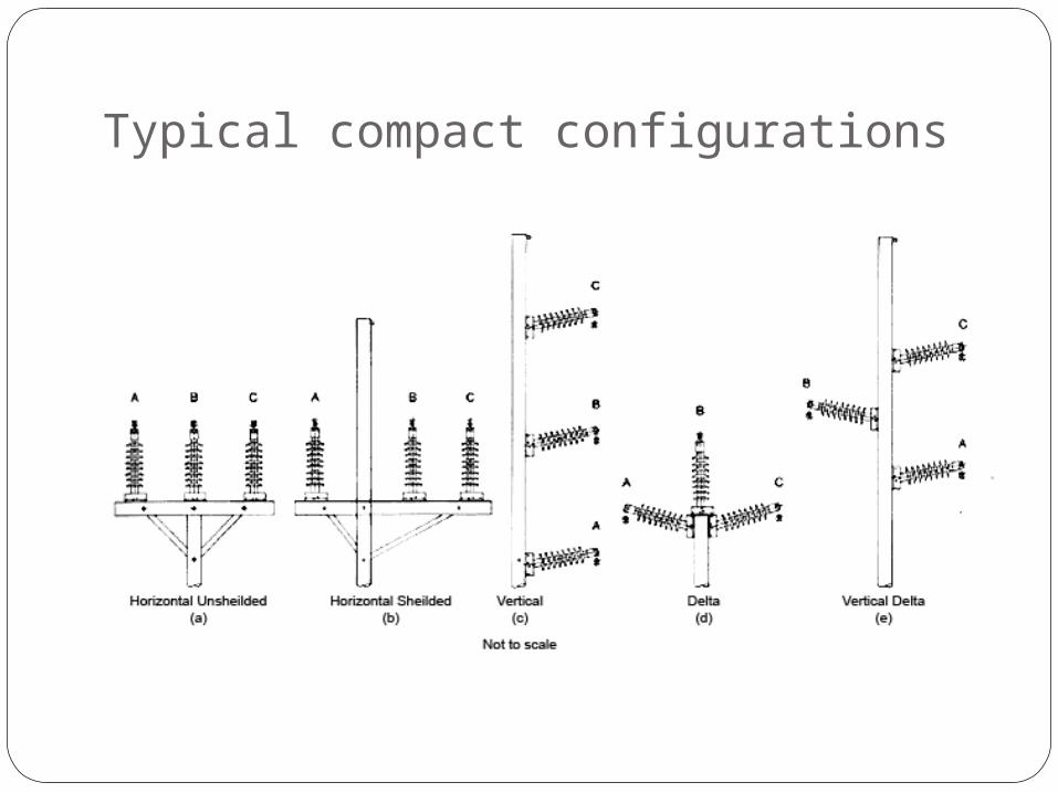
Typical compact configurations
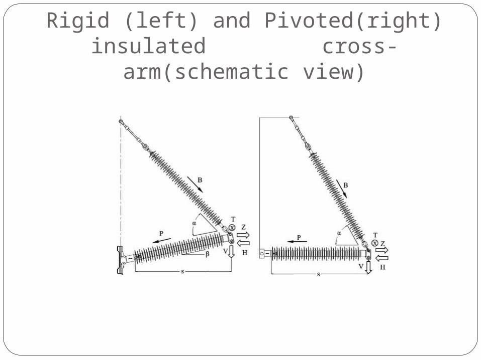
Rigid (left) and Pivoted(right) insulated cross-arm(schematic
view)
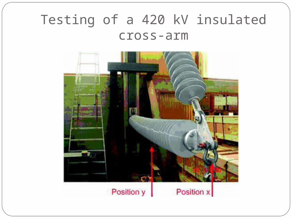
Testing of a 420 kV insulated cross-arm
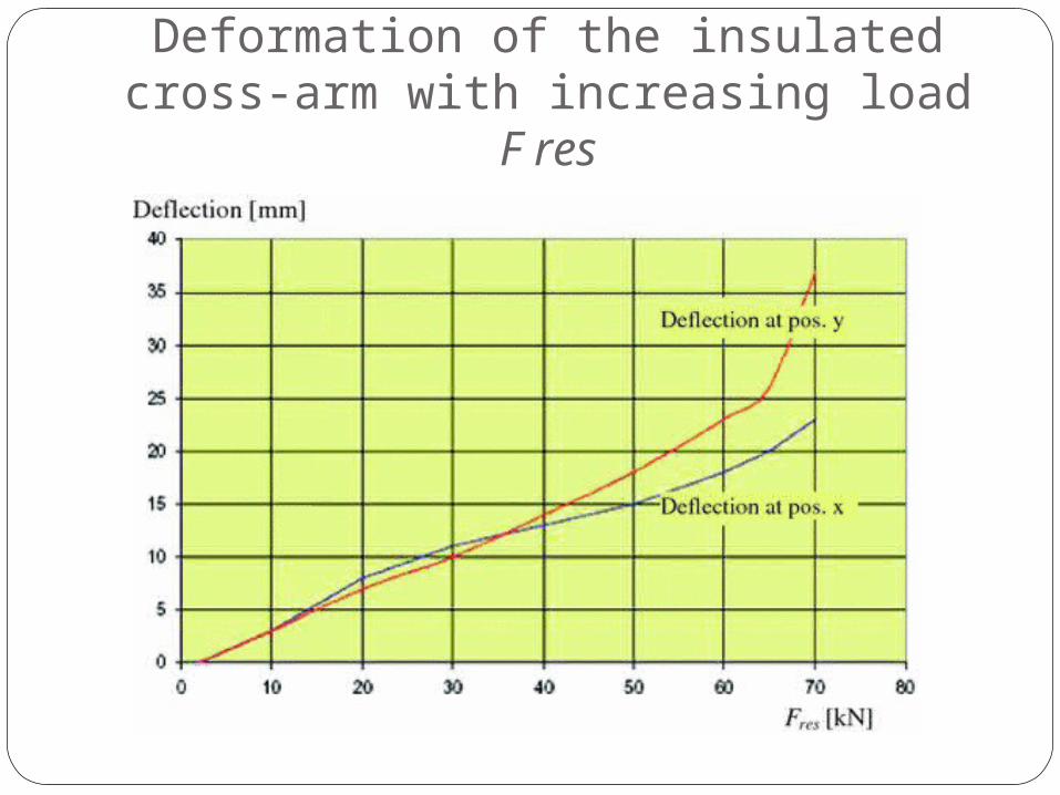
Deformation of the insulated cross-arm with increasing load F res
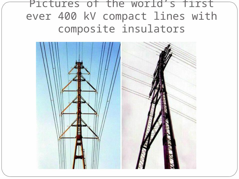
Pictures of the world’s first ever 400 kV compact lines with composite
insulators
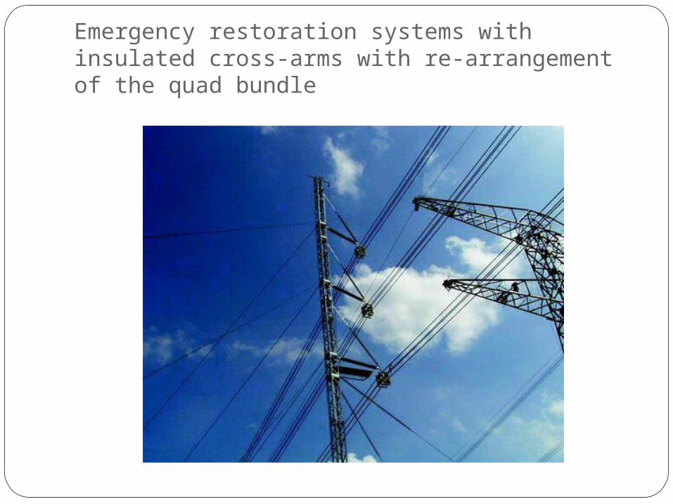
Emergency restoration systems with insulated cross-arms with re-arrangement of the quad bundle
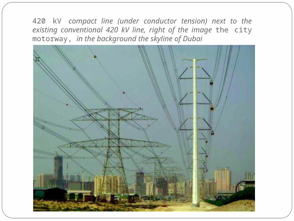
420 kV compact line (under conductor tension) next to the existing conventional 420 kV line, right of the image the city motorway, in the background the skyline of Dubai
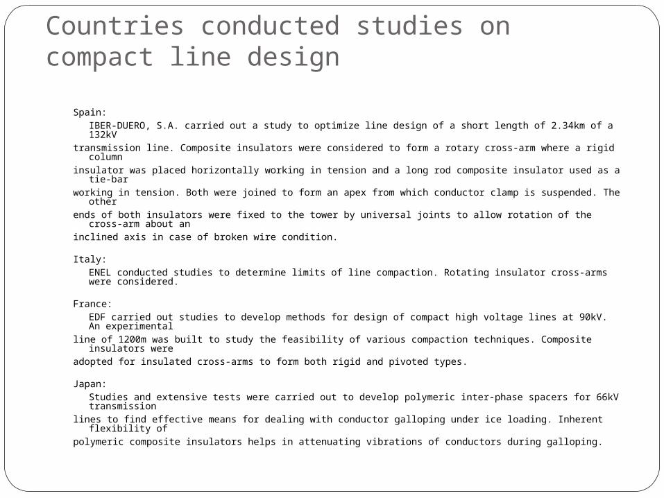
Countries conducted studies on compact line design
Spain:IBER-DUERO, S.A. carried out a study to optimize line design of a short length of 2.34km of a 132kV
transmission line. Composite insulators were considered to form a rotary cross-arm where a rigid column
insulator was placed horizontally working in tension and a long rod composite insulator used as a tie-bar working in tension. Both were joined to form an apex from which conductor clamp is suspended. The
other ends of both insulators were fixed to the tower by universal joints to allow rotation of the cross-arm
about an inclined axis in case of broken wire condition.
Italy:ENEL conducted studies to determine limits of line compaction. Rotating insulator cross-arms were considered.
France:EDF carried out studies to develop methods for design of compact high voltage lines at 90kV. An experimental
line of 1200m was built to study the feasibility of various compaction techniques. Composite insulators were
adopted for insulated cross-arms to form both rigid and pivoted types.
Japan:Studies and extensive tests were carried out to develop polymeric inter-phase spacers for 66kV transmission
lines to find effective means for dealing with conductor galloping under ice loading. Inherent flexibility of polymeric composite insulators helps in attenuating vibrations of conductors during galloping.
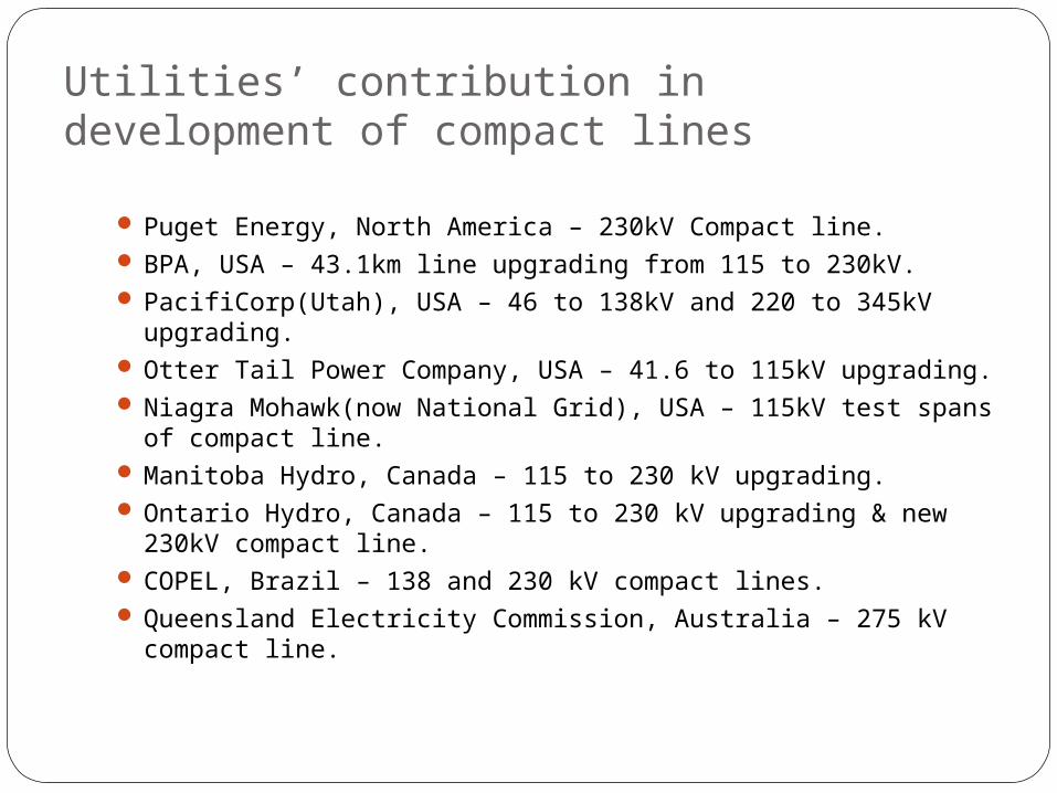
Utilities’ contribution in development of compact lines
Puget Energy, North America – 230kV Compact line. BPA, USA – 43.1km line upgrading from 115 to 230kV. PacifiCorp(Utah), USA – 46 to 138kV and 220 to 345kV
upgrading. Otter Tail Power Company, USA – 41.6 to 115kV upgrading. Niagra Mohawk(now National Grid), USA – 115kV test spans of
compact line. Manitoba Hydro, Canada – 115 to 230 kV upgrading. Ontario Hydro, Canada – 115 to 230 kV upgrading & new
230kV compact line. COPEL, Brazil – 138 and 230 kV compact lines. Queensland Electricity Commission, Australia – 275 kV
compact line.
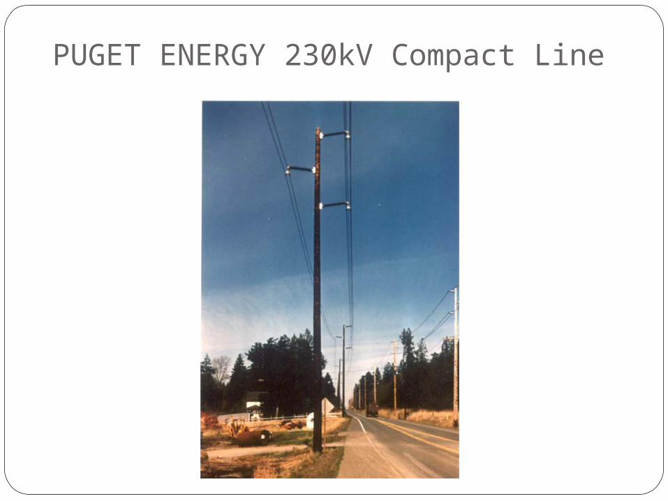
PUGET ENERGY 230kV Compact Line
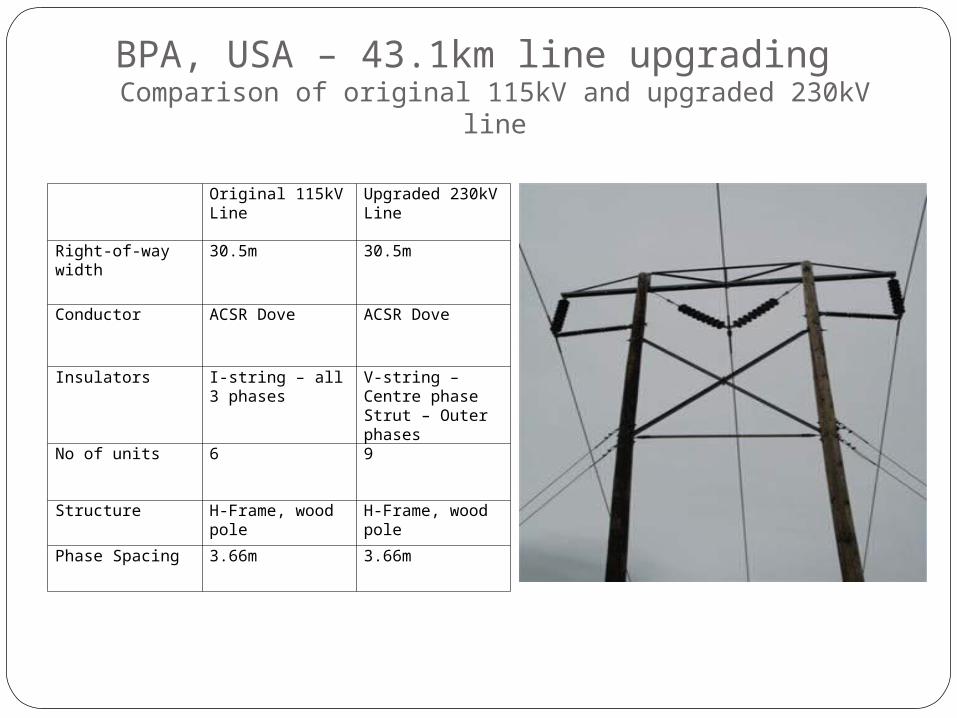
BPA, USA – 43.1km line upgrading Comparison of original 115kV and upgraded 230kV line
Original 115kV Line Upgraded 230kV Line
Right-of-way width 30.5m 30.5m
Conductor ACSR Dove ACSR Dove
Insulators I-string – all 3 phases V-string – Centre phaseStrut – Outer phases
No of units 6 9
Structure H-Frame, wood pole H-Frame, wood pole
Phase Spacing 3.66m 3.66m
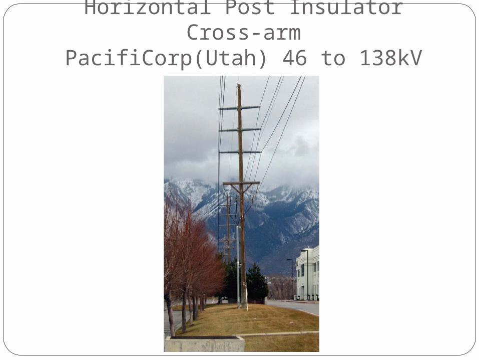
Horizontal Post Insulator Cross-armPacifiCorp(Utah) 46 to 138kV
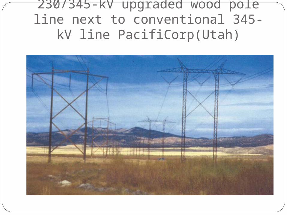
230/345-kV upgraded wood pole line next to conventional 345-kV line
PacifiCorp(Utah)
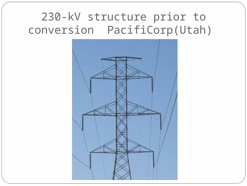
230-kV structure prior to conversion PacifiCorp(Utah)
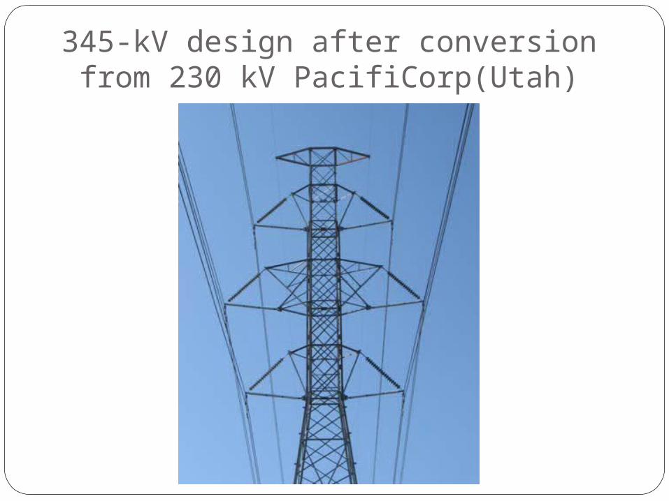
345-kV design after conversion from 230 kV PacifiCorp(Utah)
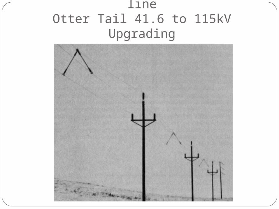
Midspan spacers used on test lineOtter Tail 41.6 to 115kV Upgrading
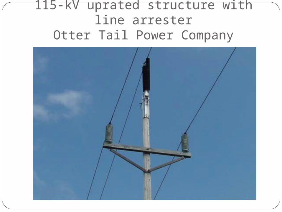
115-kV uprated structure with line arrester
Otter Tail Power Company
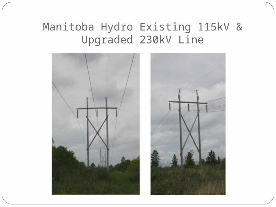
Manitoba Hydro Existing 115kV & Upgraded 230kV Line
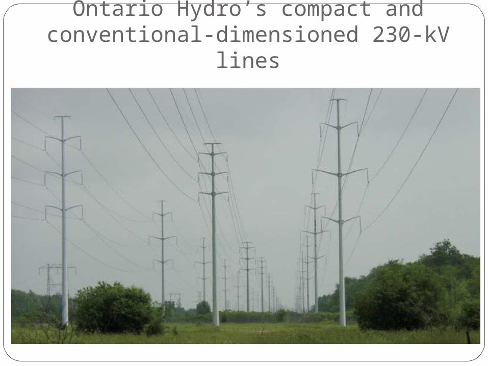
Ontario Hydro’s compact and conventional-dimensioned 230-kV
lines
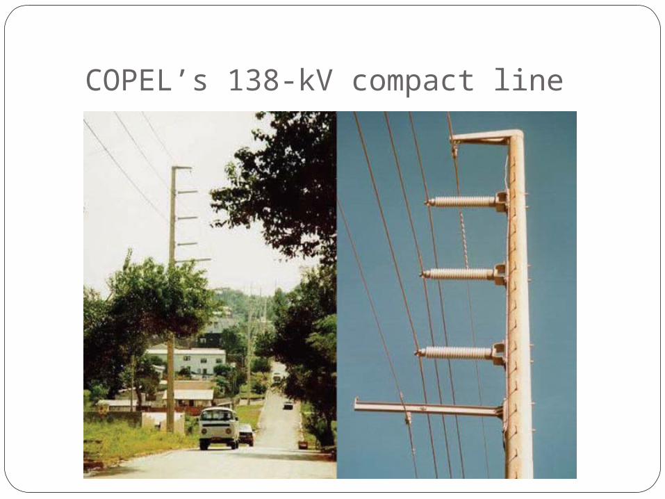
COPEL’s 138-kV compact line
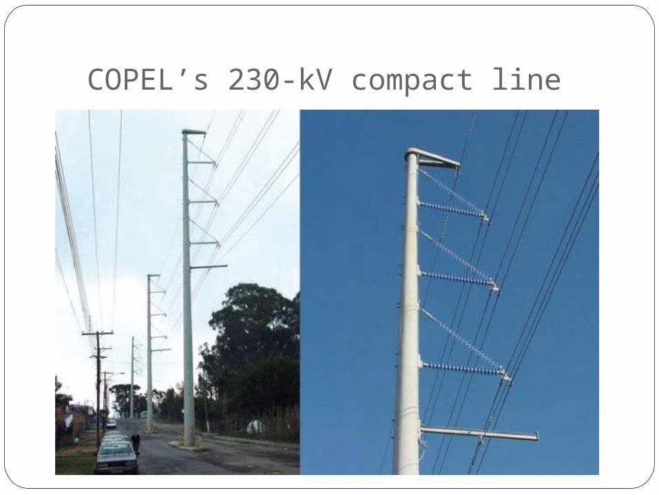
COPEL’s 230-kV compact line
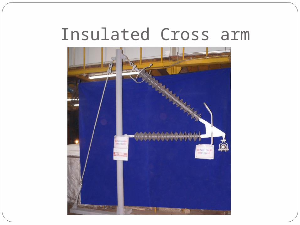
Insulated Cross arm
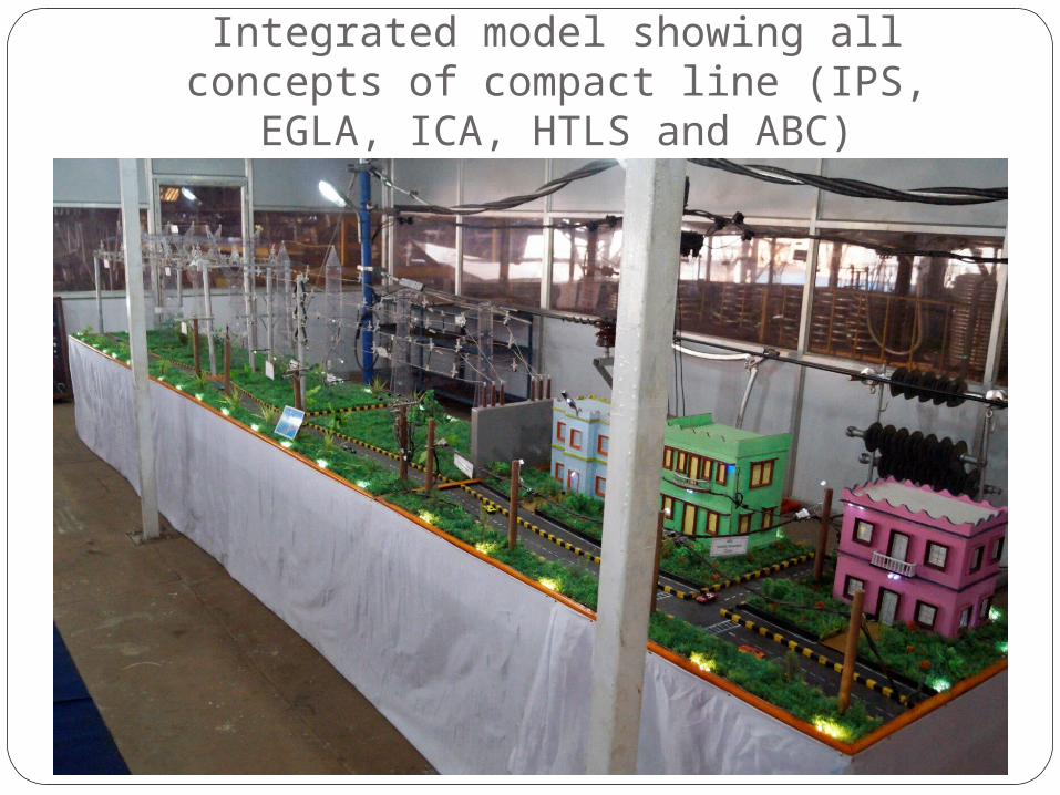
Integrated model showing all concepts of compact line (IPS, EGLA, ICA, HTLS and
ABC)

ACKNOWLEDGEMENT
Acknowledgement is expressed to EPRI, USA.
Reference and Photographs extracted for presentation from EPRI Transmission Line Reference Book – 115-345kV Compact Line design and Book on Silicon Composite Insulators by K. Papailiou et. al.
Regards and Thanks to all associates

THANK YOU