Embed Size (px)
Citation preview
Intelect® Mobile 2
ElectrotherapyUser Manual
EN
2 CONTENTS EN
INTELECT® MOBILE 2 ELECTROTHERAPY USER MANUAL
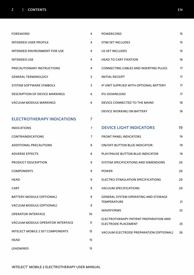
FOREWORD 4
INTENDED USER PROFILE 4
INTENDED ENVIRONMENT FOR USE 4
INTENDED USE 4
PRECAUTIONARY INSTRUCTIONS 4
GENERAL TERMINOLOGY 5
SYSTEM SOFTWARE SYMBOLS 5
DESCRIPTION OF DEVICE MARKINGS 6
VACUUM MODULE MARKINGS 6
ELECTROTHERAPY INDICATIONS 7
INDICATIONS 7
CONTRAINDICATIONS 7
ADDITIONAL PRECAUTIONS 8
ADVERSE EFFECTS 8
PRODUCT DESCRIPTION 9
COMPONENTS 9
HEAD 9
CART 9
BATTERY MODULE (OPTIONAL) 9
VACUUM MODULE (OPTIONAL) 9
OPERATOR INTERFACE 10
VACUUM MODULE OPERATOR INTERFACE 11
INTELECT MOBILE 2 SET COMPONENTS 15
HEAD 15
LEADWIRES 15
POWERCORD 15
STIM SET INCLUDES 15
US SET INCLUDES 15
HEAD TO CART FIXATION 16
CONNECTING CABLES AND INSERTING PLUGS 17
INITIAL RECEIPT 17
IF UNIT SUPPLIED WITH OPTIONAL BATTERY 17
IFU DOWNLOAD 17
DEVICE CONNECTED TO THE MAINS 18
DEVICE WORKING ON BATTERY 18
DEVICE LIGHT INDICATORS 19
FRONT PANEL INDICATORS 19
ON/OFF BUTTON BLUE INDICATOR: 19
PLAY/PAUSE BUTTON BLUE INDICATOR 19
SYSTEM SPECIFICATIONS AND DIMENSIONS 20
POWER 20
ELECTRO STIMULATION SPECIFICATIONS 20
VACUUM SPECIFICATIONS 20
GENERAL SYSTEM OPERATING AND STORAGE TEMPERATURE 21
WAVEFORMS 22
ELECTROTHERAPY PATIENT PREPARATION AND ELECTRODE PLACEMENT 25
VACUUM ELECTRODE PREPARATION (OPTIONAL) 26
3 CONTENTS EN
INTELECT® MOBILE 2 ELECTROTHERAPY USER MANUAL
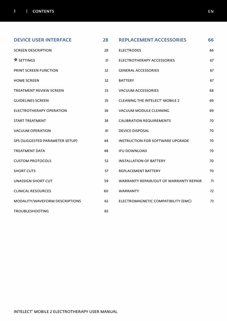
DEVICE USER INTERFACE 28
SCREEN DESCRIPTION 28
SETTINGS 31
PRINT SCREEN FUNCTION 32
HOME SCREEN 32
TREATMENT REVIEW SCREEN 33
GUIDELINES SCREEN 35
ELECTROTHERAPY OPERATION 36
START TREATMENT 38
VACUUM OPERATION 41
SPS (SUGGESTED PARAMETER SETUP) 44
TREATMENT DATA 48
CUSTOM PROTOCOLS 53
SHORT CUTS 57
UNASSIGN SHORT CUT 59
CLINICAL RESOURCES 60
MODALITY/WAVEFORM DESCRIPTIONS 63
TROUBLESHOOTING 65
REPLACEMENT ACCESSORIES 66
ELECTRODES 66
ELECTROTHERAPY ACCESSORIES 67
GENERAL ACCESSORIES 67
BATTERY 67
VACUUM ACCESSORIES 68
CLEANING THE INTELECT® MOBILE 2 69
VACUUM MODULE CLEANING 69
CALIBRATION REQUIREMENTS 70
DEVICE DISPOSAL 70
INSTRUCTION FOR SOFTWARE UPGRADE 70
IFU DOWNLOAD 70
INSTALLATION OF BATTERY 70
REPLACEMENT BATTERY 70
WARRANTY REPAIR/OUT OF WARRANTY REPAIR 71
WARRANTY 72
ELECTROMAGNETIC COMPATIBILITY (EMC) 73
4 INTRODUCTION EN
INTELECT® MOBILE 2 ELECTROTHERAPY USER MANUAL
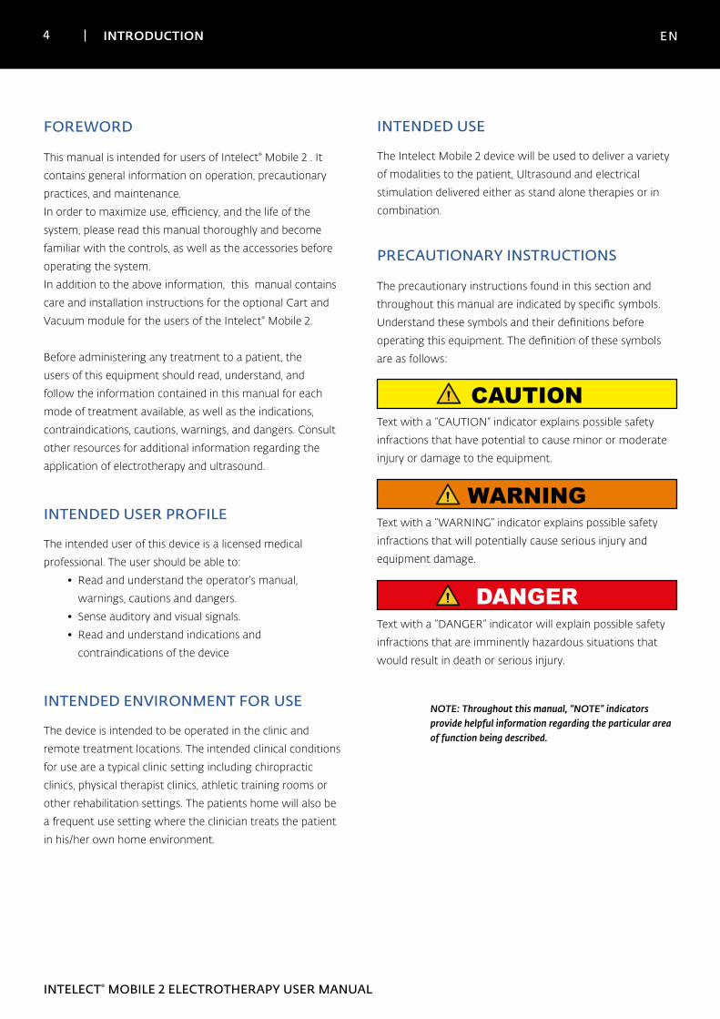
This manual is intended for users of Intelect® Mobile 2 . It
contains general information on operation, precautionary
practices, and maintenance.
In order to maximize use, efficiency, and the life of the
system, please read this manual thoroughly and become
familiar with the controls, as well as the accessories before
operating the system.
In addition to the above information, this manual contains
care and installation instructions for the optional Cart and
Vacuum module for the users of the Intelect® Mobile 2.
Before administering any treatment to a patient, the
users of this equipment should read, understand, and
follow the information contained in this manual for each
mode of treatment available, as well as the indications,
contraindications, cautions, warnings, and dangers. Consult
other resources for additional information regarding the
application of electrotherapy and ultrasound.
INTENDED USER PROFILE
The intended user of this device is a licensed medical
professional. The user should be able to:
• Read and understand the operator’s manual,
warnings, cautions and dangers.
• Sense auditory and visual signals.
• Read and understand indications and
contraindications of the device
INTENDED ENVIRONMENT FOR USE
The device is intended to be operated in the clinic and
remote treatment locations. The intended clinical conditions
for use are a typical clinic setting including chiropractic
clinics, physical therapist clinics, athletic training rooms or
other rehabilitation settings. The patients home will also be
a frequent use setting where the clinician treats the patient
in his/her own home environment.
FOREWORD
NOTE: Throughout this manual, “NOTE” indicators provide helpful information regarding the particular area of function being described.
CAUTIONText with a “CAUTION” indicator explains possible safety
infractions that have potential to cause minor or moderate
injury or damage to the equipment.
Text with a “WARNING” indicator explains possible safety
infractions that will potentially cause serious injury and
equipment damage.
Text with a “DANGER” indicator will explain possible safety
infractions that are imminently hazardous situations that
would result in death or serious injury.
The precautionary instructions found in this section and
throughout this manual are indicated by specific symbols.
Understand these symbols and their definitions before
operating this equipment. The definition of these symbols
are as follows:
PRECAUTIONARY INSTRUCTIONS
WARNING
DANGER
INTENDED USE
The Intelect Mobile 2 device will be used to deliver a variety
of modalities to the patient, Ultrasound and electrical
stimulation delivered either as stand alone therapies or in
combination.
5 INTRODUCTION EN
INTELECT® MOBILE 2 ELECTROTHERAPY USER MANUAL
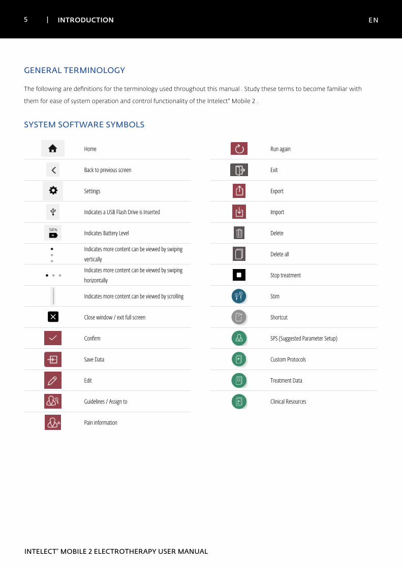
GENERAL TERMINOLOGY
The following are definitions for the terminology used throughout this manual . Study these terms to become familiar with
them for ease of system operation and control functionality of the Intelect® Mobile 2 .
SYSTEM SOFTWARE SYMBOLS
Home
Back to previous screen
Settings
Indicates a USB Flash Drive is Inserted
Indicates Battery Level
Indicates more content can be viewed by swiping
vertically
Indicates more content can be viewed by swiping
horizontally
Indicates more content can be viewed by scrolling
Close window / exit full screen
Confirm
Save Data
Edit
Guidelines / Assign to
Pain information
Run again
Exit
Export
Import
Delete
Delete all
Stop treatment
Stim
Shortcut
SPS (Suggested Parameter Setup)
Custom Protocols
Treatment Data
Clinical Resources
6 INTRODUCTION EN
INTELECT® MOBILE 2 ELECTROTHERAPY USER MANUAL
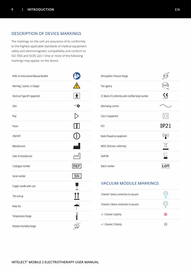
DESCRIPTION OF DEVICE MARKINGS
The markings on the unit are assurance of its conformity
to the highest applicable standards of medical equipment
safety and electromagnetic compatibility and conform to
ISO 7010 and ISO15-223-1 One or more of the following
markings may appear on the device:
Refer to Instructional Manual Booklet
Warning, Caution, or Danger
Electrical Type BF Equipment
Stim
Play
Pause
ON/OFF
Manufacturer
Date of manufacture
Catalogue number
Serial number
Fragile, handle with care
This end up
Keep dry
Temperature Range
Relative Humidity Range
Atmospheric Pressure Range
Test agency
CE Mark of Conformity with notified body number
Alternating current
Class II equipment
IP21
Radio frequency equipment
WEEE Directive conformity
Shelf life
Batch number
VACUUM MODULE MARKINGS
Channel 1 device connection to vacuum 1 2
Channel 2 device connection to vacuum 1 2
+/- Channel 1 polarity
1 2
+/- Channel 2 Polarity
1 2
7 INDICATIONS FOR USE EN
INTELECT® MOBILE 2 ELECTROTHERAPY USER MANUAL
INDICATIONS
TENS
• Symptomatic relief of chronic pain
• Management of post-operative pain
NMES
• Muscle re-education
• Increasing local blood supply
• Relaxation of muscle spasms
• Maintaining/Increasing range of motion
CONTRAINDICATIONS
The Intelect® Mobile 2 should NOT be used under the
following conditions:
• Do not use for symptomatic local pain relief unless
etiology is established or unless a pain syndrome has
been diagnosed.
• Do not use when cancerous lesions are present in the
treatment area.
• Do not apply stimulation over swollen, infected,
inflamed areas or skin eruptions (e.g., phlebitis,
thrombophlebitis, varicose veins, etc.).
• Do not use when patient is suspected or known to
have infectious disease and/or disease where it is
advisable, for general medical purposes, to suppress
heat or fevers.
• Do not place electrode placements to the carotid
sinus region (anterior neck) or transcerebrally
(through the head).
• Do not use on pregnant women. Safety has not
been established for the use of therapeutic electrical
stimulation during pregnancy.
• Do not use Intelect® Mobile 2 on patients who have
or have had implantable neurostimulating cardiac
demand pacemakers, ICD, or other implantable
electronic devices.
• Do not use Intelect® Mobile 2 on patients with body
worn electro mechanical medical devices, i.e. insulin
pump.
• Do not use this system in an MRI or CT environment.
The Intelect® Mobile 2, its components, and
accessories are not to be present in an MRI or CT
environment.
• Do not apply stimulation transthoraticorally or on the
chest, the introduction of electrical current into the
heart may cause cardiac arrhythmia
• Do not apply stimulation over the anterior neck or
mouth. Severe spasm of the laryngeal and pharyngeal
muscles may occur and the contractions may be
strong enough to close the airway or cause difficulty
in breathing.
ELECTROTHERAPY INDICATIONS
8 INDICATIONS FOR USE EN
INTELECT® MOBILE 2 ELECTROTHERAPY USER MANUAL
ADDITIONAL PRECAUTIONS
• Use caution for patients with suspected or diagnosed
heart problems.
• Use caution for patients with suspected or diagnosed
epilepsy.
• Use caution in the presence of the following:
» When there is a tendency to hemorrhage
following acute trauma or fracture
» Following recent surgical procedures when
muscle contraction may disrupt the healing
process
» Over a menstruating or pregnant uterus
» Over areas of the skin that lack normal
sensation
• Powered muscle stimulators should be used only
with the lead wires and electrodes recommended for
use by the manufacturer.
• With TENS waveforms, isolated cases of skin irritation
may occur at the site of electrode placement
following long-term application.
• The effective management of pain by TENS
waveforms is highly dependent upon patient
selection by a person qualified in pain management.
ELECTROTHERAPY INDICATIONS (CONTINUED)
ADVERSE EFFECTS
• Skin irritation and burns beneath the electrodes
have been reported with the use of powered muscle
stimulators. The irritation can usually be reduced
by using an alternative conductive medium or an
alternative electrode placement
• Potential adverse effects with TENS are skin irritation
and electrode burns
Note: 1. Skin irritation and burns beneath the electrodes can be reduced or avoided by using appropriate electrode size and ensuring optimal contact quality. If any question arises as to the proper electrode size, consult a licensed practitioner prior to therapy session.
2.Some people, with very sensitive skin, may experience redness under the electrodes after a session. Generally, this redness is totally harmless and usually disappears after 10 to 20 minutes. However, do not start another stimulation session on the same area if the redness is still visible
9 DEVICE DESCRIPTION EN
INTELECT® MOBILE 2 ELECTROTHERAPY USER MANUAL
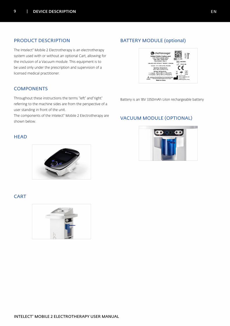
PRODUCT DESCRIPTION
The Intelect® Mobile 2 Electrotherapy is an electrotherapy
system used with or without an optional Cart, allowing for
the inclusion of a Vacuum module. This equipment is to
be used only under the prescription and supervision of a
licensed medical practitioner.
COMPONENTS
Throughout these instructions the terms “left” and“right”
referring to the machine sides are from the perspective of a
user standing in front of the unit.
The components of the Intelect® Mobile 2 Electrotherapy are
shown below.
HEAD
CART
BATTERY MODULE (optional)
Battery is an 18V 3350mAh LiIon rechargeable battery
VACUUM MODULE (OPTIONAL)
10 DEVICE DESCRIPTION EN
INTELECT® MOBILE 2 ELECTROTHERAPY USER MANUAL
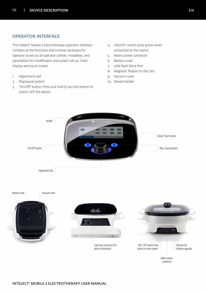
OPERATOR INTERFACE
4. ON/OFF switch (only active when
connected to the mains)
5. Mains power connector
6. Battery cover
7. USB Flash Drive Port
8. Magnetic fixation to the cart
9. Vacuum cover
10. Device handle
The Intelect® Mobile 2 Electrotherapy Operator Interface
contains all the functions and controls necessary for
operator access to all operator utilities, modalities, and
parameters for modification and system set up. Color
Display and touch screen
1. Adjustment dial
2. Play/pause button
3. “On/Off“ button. Press and hold (2 sec) the button to
switch OFF the device.
Lead wire connectors for electro stimulation
ON / OFF switch only active on mains power
USB port for software upgrade
Mains power connector
Battery cover Vacuum cover
Handle
Colour Touch Screen
Play / pause button
Adjustment dial
“On/Off“ button
1 1 DEVICE DESCRIPTION EN
INTELECT® MOBILE 2 ELECTROTHERAPY USER MANUAL
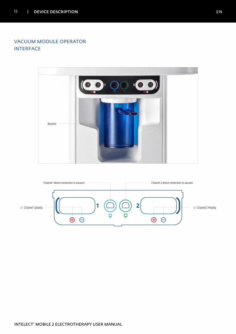
1 2
Channel 2 device connection to vacuumChannel 1 device connection to vacuum
+/- Channel 1 polarity +/- Channel 2 Polarity
VACUUM MODULE OPERATOR INTERFACE
Resevoir
12 GENERAL WARNINGS AND PRECAUTIONS EN
INTELECT® MOBILE 2 ELECTROTHERAPY USER MANUAL
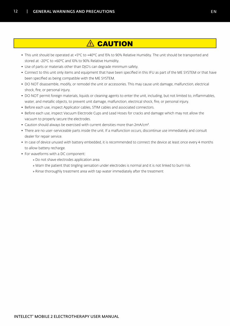
CAUTION
• This unit should be operated at +5°C to +40°C and 15% to 90% Relative Humidity. The unit should be transported and
stored at -20°C to +60°C and 10% to 90% Relative Humidity.
• Use of parts or materials other than DJO’s can degrade minimum safety.
• Connect to this unit only items and equipment that have been specified in this IFU as part of the ME SYSTEM or that have
been specified as being compatible with the ME SYSTEM.
• DO NOT disassemble, modify, or remodel the unit or accessories. This may cause unit damage, malfunction, electrical
shock, fire, or personal injury.
• DO NOT permit foreign materials, liquids or cleaning agents to enter the unit, including, but not limited to, inflammables,
water, and metallic objects, to prevent unit damage, malfunction, electrical shock, fire, or personal injury.
• Before each use, inspect Applicator cables, STIM cables and associated connectors.
• Before each use, inspect Vacuum Electrode Cups and Lead Hoses for cracks and damage which may not allow the
vacuum to properly secure the electrodes.
• Caution should always be exercised with current densities more than 2mA/cm².
• There are no user-serviceable parts inside the unit. If a malfunction occurs, discontinue use immediately and consult
dealer for repair service.
• In case of device unused with battery embedded, it is recommended to connect the device at least once every 4 months
to allow battery recharge.
• For waveforms with a DC component:
» Do not shave electrodes application area
» Warn the patient that tingling sensation under electrodes is normal and it is not linked to burn risk.
» Rinse thoroughly treatment area with tap water immediately after the treatment
13 GENERAL WARNINGS AND PRECAUTIONS EN
INTELECT® MOBILE 2 ELECTROTHERAPY USER MANUAL
WARNING
• This device should be used only under the continued supervision of a physician or licensed practitioner.
• Contaminated sponges, electrodes, leadwires, and gel can lead to infection.
• Use of electrode on multiple patients can lead to infection.
• Do not apply electro stimulation treatment during bath, shower, sauna,..
• DO NOT operate the Intelect® Mobile 2 within the vicinity or environment of an ultrasonic diathermy system.
• DO NOT operate the Intelect® Mobile 2 within the vicinity or environment of any microware and RF shortwave
diathermy system.
• DO NOT operate this unit in an environment where other devices are being used that intentionally radiate
electromagnetic energy in an unshielded manner.
• Electronic monitoring equipment (such as ECG monitors and ECG alarms) may not operate properly when electrical
stimulation is in use.
• Simultaneous connection of a PATIENT to a high frequency surgical ME EQUIPMENT may result in burns at the site of the
STIMULATOR electrodes and possible damage to the STIMULATOR.
• Portable RF communications equipment should be used no closer than 30 cm (12 inches) to any part of the Intelect
Mobile 2, including cables specified by the manufacturer. Otherwise, degradation of the performance of this equipment
could result.
• Use of accessories, transducers and cables other than those specified or provided by the manufacturer of this equipment
could result in increased electromagnetic emissions or decreased electromagnetic immunity of this equipment and result
in improper operation.
• Battery replacement by inadequately trained personnel could result in fire or explosion. Please read carefully the battery
replacement instructions in the Mobile 2 IFU before attempting to replace the battery.
• Device is designed to comply with electromagnetic safety standards. This equipment generates, uses, and can radiate
radio frequency energy and, if not installed and used in accordance with instructions for use, may cause harmful
interference to other devices in the vicinity. Harmful interference to other devices can be determined by turning this
equipment on and off. Try to correct the interference using one or more of the following:
» Reorient or relocate the receiving device
» Increase the separation between the equipment
» Connect the equipment to an outlet on a different circuit from that to which the other device(s) are connected
» Consult your authorized DJO dealer for help.
• Disconnect the system from the power source before attempting any maintenance, installation, removal, or replacement
procedures to prevent electrical shock and possible damage to system.
• The Intelect® Mobile 2 may be susceptible to Electro-Static Discharge (ESD) at greater than ±6 kV when first grasping
the Ultrasound applicator. In the event of such a discharge, the Intelect® Mobile 2 may display a permanent error. The
Intelect® Mobile 2 will terminate all active outputs (stim, ultrasound,), automatically place the unit in a safe state.
14 GENERAL WARNINGS AND PRECAUTIONS EN
INTELECT® MOBILE 2 ELECTROTHERAPY USER MANUAL
DANGER
• DO NOT connect the unit to an electrical supply without first verifying that the power supply is the correct voltage.
Incorrect voltage may cause unit damage, malfunction, electrical shock, fire, or personal injury. Your unit was constructed
to operate only on the electrical voltage specified on the Voltage Rating and Serial Number Plate. Contact your DJO
dealer if the unit is not properly rated.
• Device is not designed to be used in oxygen rich environment, Explosion hazard if the device is used in the presence of
flammable anesthetic mixture with air, oxygen, or nitrous oxide.
15 DETAIL DEVICE DESCRIPTION EN
INTELECT® MOBILE 2 ELECTROTHERAPY USER MANUAL
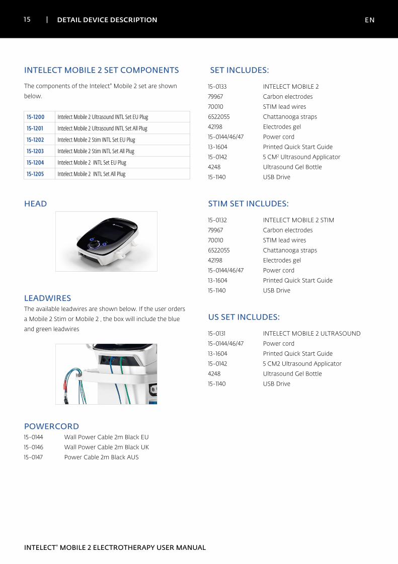
The components of the Intelect® Mobile 2 set are shown
below.
15-1200 Intelect Mobile 2 Ultrasound INTL Set EU Plug
15-1201 Intelect Mobile 2 Ultrasound INTL Set All Plug
15-1202 Intelect Mobile 2 Stim INTL Set EU Plug
15-1203 Intelect Mobile 2 Stim INTL Set All Plug
15-1204 Intelect Mobile 2 INTL Set EU Plug
15-1205 Intelect Mobile 2 INTL Set All Plug
HEAD
LEADWIRESThe available leadwires are shown below. If the user orders
a Mobile 2 Stim or Mobile 2 , the box will include the blue
and green leadwires
POWERCORD15-0144 Wall Power Cable 2m Black EU
15-0146 Wall Power Cable 2m Black UK
15-0147 Power Cable 2m Black AUS
INTELECT MOBILE 2 SET COMPONENTS SET INCLUDES:
15-0133 INTELECT MOBILE 2
79967 Carbon electrodes
70010 STIM lead wires
6522055 Chattanooga straps
42198 Electrodes gel
15-0144/46/47 Power cord
13-1604 Printed Quick Start Guide
15-0142 5 CM2 Ultrasound Applicator
4248 Ultrasound Gel Bottle
15-1140 USB Drive
STIM SET INCLUDES:
15-0132 INTELECT MOBILE 2 STIM
79967 Carbon electrodes
70010 STIM lead wires
6522055 Chattanooga straps
42198 Electrodes gel
15-0144/46/47 Power cord
13-1604 Printed Quick Start Guide
15-1140 USB Drive
US SET INCLUDES:
15-0131 INTELECT MOBILE 2 ULTRASOUND
15-0144/46/47 Power cord
13-1604 Printed Quick Start Guide
15-0142 5 CM2 Ultrasound Applicator
4248 Ultrasound Gel Bottle
15-1140 USB Drive
16 SETUP INSTRUCTIONS EN
INTELECT® MOBILE 2 ELECTROTHERAPY USER MANUAL
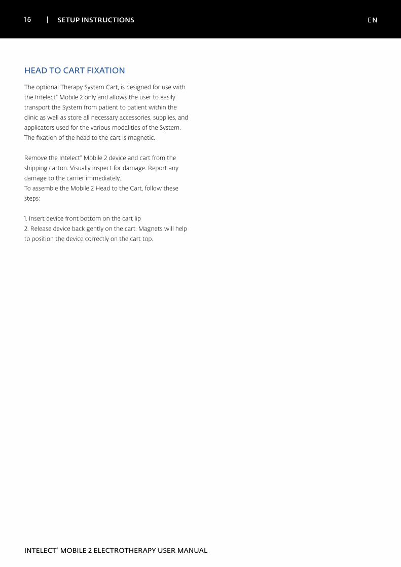
The optional Therapy System Cart, is designed for use with
the Intelect® Mobile 2 only and allows the user to easily
transport the System from patient to patient within the
clinic as well as store all necessary accessories, supplies, and
applicators used for the various modalities of the System.
The fixation of the head to the cart is magnetic.
Remove the Intelect® Mobile 2 device and cart from the
shipping carton. Visually inspect for damage. Report any
damage to the carrier immediately.
To assemble the Mobile 2 Head to the Cart, follow these
steps:
1. Insert device front bottom on the cart lip
2. Release device back gently on the cart. Magnets will help
to position the device correctly on the cart top.
HEAD TO CART FIXATION
17 SETUP INSTRUCTIONS EN
INTELECT® MOBILE 2 ELECTROTHERAPY USER MANUAL
CONNECTING CABLES AND INSERTING PLUGS
When inserting the plugs, be sure to align the flat side of the
plug with the flat side of the slot and push in gently. This is
to avoid bending the pins in the plug.
Insert cable into the appropriate connector prior to starting
therapy.
INITIAL RECEIPT
Remove all packaging
IF UNIT SUPPLIED WITH OPTIONAL BATTERY
After unpacking Intelect Mobile 2 to fit the battery follow
the following steps
1. Unscrew the battery cover from the base of the device by
removing the 2 screws see below
2. Remove the battery cover
3. Plug the battery into the battery connector on the device
4. Insert the battery into its location
5. Replace the 2 screws to close the battery cover
POWERING UP THE DEVICEFirst time use always use mains power even if battery
connected. Insert the power cord into the back of the unit,
insert the plug into a power outlet, do not position the
Intelect Mobile 2 in such a way that makes it difficult to
disconnect from the mains power.
Switch device on with ON/OFF switch switch on the back of
the unit
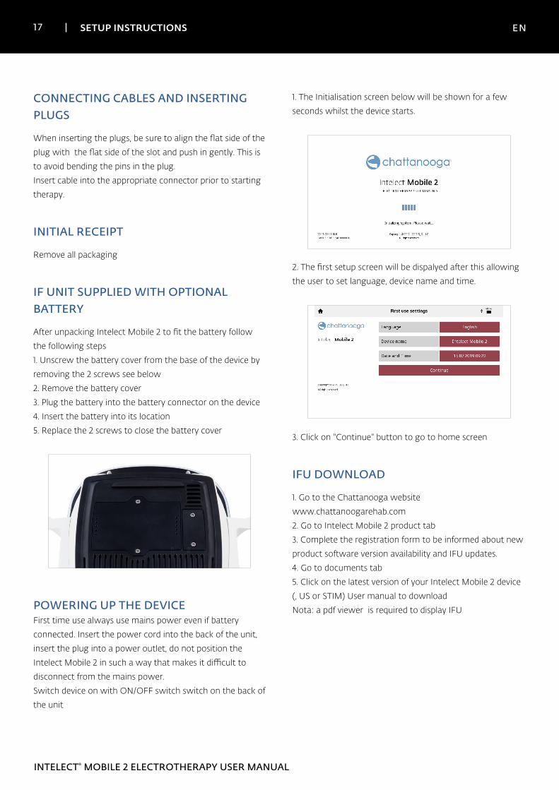
1. The Initialisation screen below will be shown for a few
seconds whilst the device starts.
2. The first setup screen will be dispalyed after this allowing
the user to set language, device name and time.
3. Click on "Continue" button to go to home screen
IFU DOWNLOAD
1. Go to the Chattanooga website
www.chattanoogarehab.com
2. Go to Intelect Mobile 2 product tab
3. Complete the registration form to be informed about new
product software version availability and IFU updates.
4. Go to documents tab
5. Click on the latest version of your Intelect Mobile 2 device
(, US or STIM) User manual to download
Nota: a pdf viewer is required to display IFU
18 SETUP INSTRUCTIONS EN
INTELECT® MOBILE 2 ELECTROTHERAPY USER MANUAL
DEVICE CONNECTED TO THE MAINS
1. Plug the Power cord into the back of device. Plug the other
end of the cord into an electrical outlet.
NOTE: The Power Cord may be unplugged from the back of
the unit in an emergency situation.
2. Turn on the ON/OFF switch located on the back of the
device.
3. Select desired function on the Home Screen
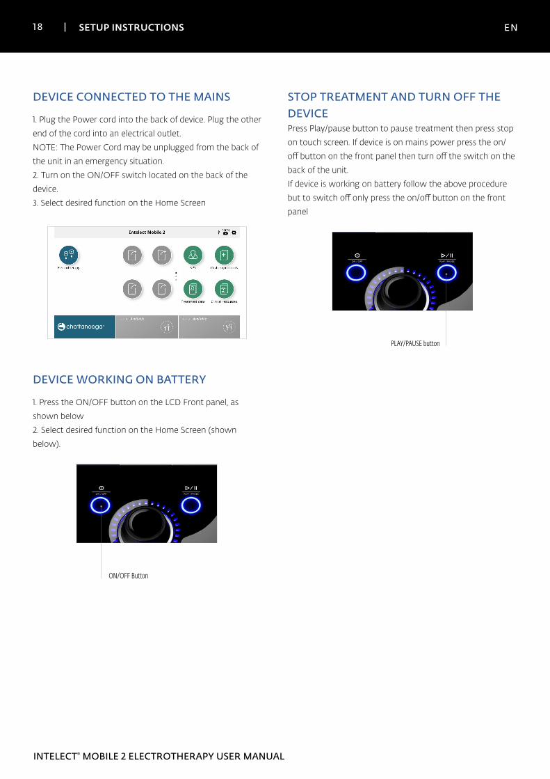
DEVICE WORKING ON BATTERY
1. Press the ON/OFF button on the LCD Front panel, as
shown below
2. Select desired function on the Home Screen (shown
below).
ON/OFF Button
STOP TREATMENT AND TURN OFF THE DEVICEPress Play/pause button to pause treatment then press stop
on touch screen. If device is on mains power press the on/
off button on the front panel then turn off the switch on the
back of the unit.
If device is working on battery follow the above procedure
but to switch off only press the on/off button on the front
panel
PLAY/PAUSE button
19 SETUP INSTRUCTIONS EN
INTELECT® MOBILE 2 ELECTROTHERAPY USER MANUAL
Intelect Mobile 2 ELECTROTHERAPY has several light
indicators:
FRONT PANEL INDICATORS:
1. Colors:
• Dark blue indicator around Electrostimulation
Channel 1
• Green indicator around Electrostimulation Channel 2
2. Behaviour:
• Steady when modality is selected and output is not
active
• Flashing when output is active
• Quickly flashing when treatment is interrupted and
user action is requested
ON/OFF BUTTON BLUE INDICATOR:
• steady ON from device connection to the mains
• Flashing while powering ON/OFF
PLAY/PAUSE BUTTON BLUE INDICATOR:
• It flashes when user can start/resume a treatment.
Otherwise, steady.
DEVICE LIGHT INDICATORS
20 SYSTEM EN
INTELECT® MOBILE 2 ELECTROTHERAPY USER MANUAL
POWER
Input 100 - 240 V AC, 1.0 to 0.42 A, 50/60 Hz
Electrical Class CLASS II
Mode of Operation Continuous
Note: Mains isolation is achieved by use of the double pole switch located on the rear panel.
Electrical Type (Degree of Protection)
Electrotherapy .TYPE BF
Electrotherapy Vacuum .TYPE BF
ELECTRO STIMULATION SPECIFICATIONS
Output specifications are described for each waveform from
pages 24-26.
Unless otherwise specified, electrotherapy controls accuracy
is: ± 20 %.
Load impedance: 500-1000 Ohm
CC = constant current, effect of load impedance on voltage
CV = constant voltage, effect of load impedance on current
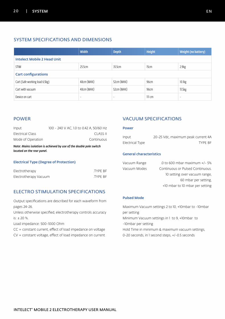
SYSTEM SPECIFICATIONS AND DIMENSIONS
Width Depth Height Weight (no battery)
Intelect Mobile 2 Head Unit
STIM 25.5cm 35.5cm 15cm 2.9kg
Cart configurations
Cart (Safe working load 6.5kg) 48cm (MAX) 52cm (MAX) 96cm 10.1kg
Cart with vacuum 48cm (MAX) 52cm (MAX) 96cm 11.5kg
Device on cart - - 111 cm -
VACUUM SPECIFICATIONS
Power
Input 20-25 Vdc, maximum peak current 4A
Electrical Type TYPE BF
General characteristics
Vacuum Range .0 to 600 mbar maximum +/- 5%
Vacuum Modes Continuous or Pulsed Continuous.
10 setting over vacuum range,
60 mbar per setting,
+10 mbar to 10 mbar per setting
Pulsed Mode
Maximum Vacuum settings 2 to 10, +10mbar to -10mbar
per setting
Minimum Vacuum settings in 1 to 9, +10mbar to
-10mbar per setting
Hold Time in minimum & maximum vacuum settings,
0-20 seconds, in 1 second steps, +/-0.5 seconds
21 SYSTEM EN
INTELECT® MOBILE 2 ELECTROTHERAPY USER MANUAL
GENERAL SYSTEM OPERATING AND STORAGE TEMPERATURE
Operating Conditions
The device will meet its requirement under the following
conditions:
Temperature: 5°C to 40°C
Relative Humidity: 15% to 90%
Atmospheric Pressure: 70kPa to 106kPa
Transport and Storage Conditions
The device will remain in proper condition under the
following conditions:
Temperature: -20°C to 60°C
Relative Humidity: 10% to 90%
Atmospheric Pressure: 50kPa to 106kPa
Time required for the Intelect Mobile 2 to warm from the
minimum storage temperature between uses until the
Intelect Mobile 2 is ready for its INTENDED USE when the
ambient temperature is 20 °C: 5h
Time required for the Intelect Mobile 2 to cool from the
maximum storage temperature between uses until the
Intelect Mobile 2 is ready for its INTENDED USE when the
ambient temperature is 20 °C: 5h
IPXX Rating for Unit
Rated to IP21
IP2* Protection against fingers or other object not greater
than 80mm in length and 12mm in diameter
*1 Protection from vertically dripping water
IPXX Rating for US applicator
Rated to IPX7
IPX7 Protection from immersed in water (up to 1m depth)
RED
RF transmitter/receiver characteristics:
- Frequency Band transmission: 2400–2483.5 MHz
- Modulation type: GFSK
- Data rate: up to 2Mbps 500kHz deviation at 2Mbps
- Effective radiated power: +6dBm
22 SYSTEM EN
INTELECT® MOBILE 2 ELECTROTHERAPY USER MANUAL
Advice on size and type of electrodes to be used is given in
device GUI treatment guidelines. For additional information
on Waveforms and output energy, refer to APPENDIX 3 on
page 88.
CC: Constant Current CV: Constant Voltage
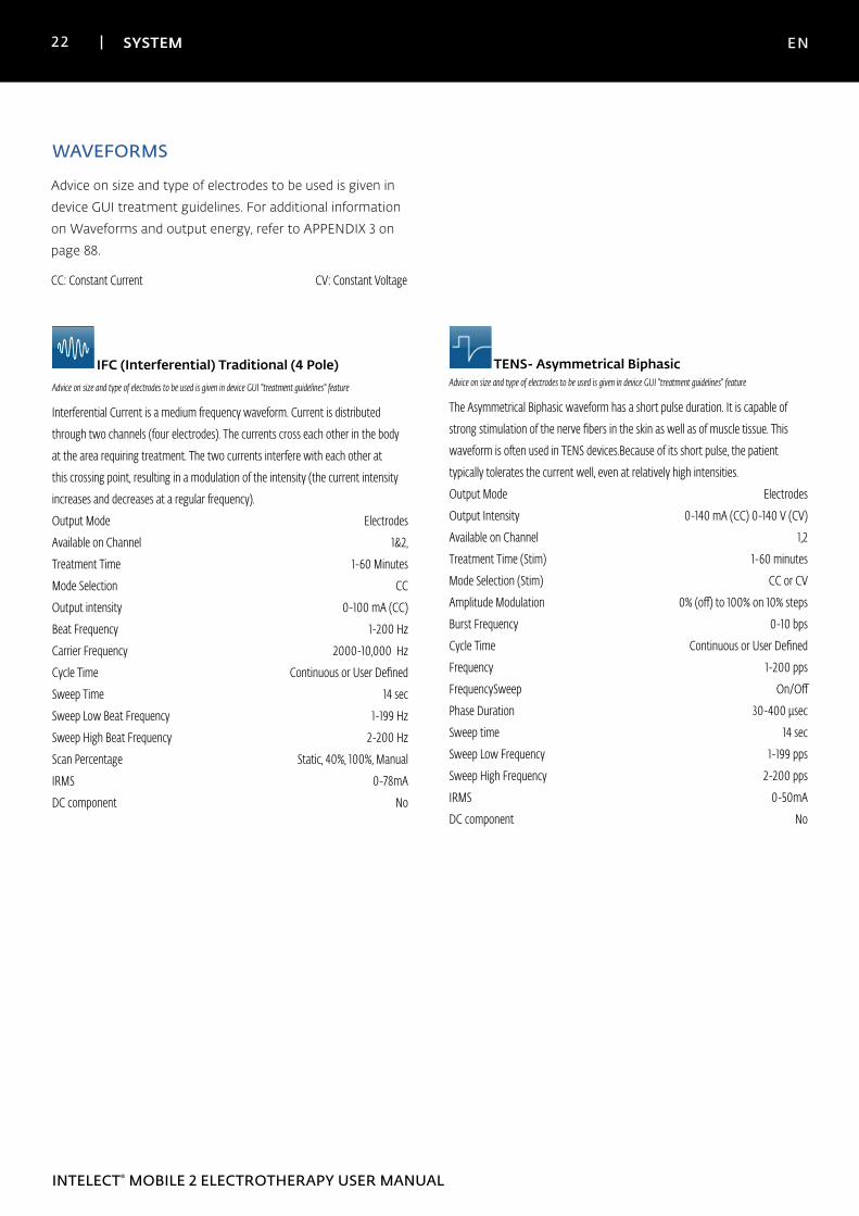
WAVEFORMS
TENS- Asymmetrical BiphasicAdvice on size and type of electrodes to be used is given in device GUI "treatment guidelines" feature
The Asymmetrical Biphasic waveform has a short pulse duration. It is capable of
strong stimulation of the nerve fibers in the skin as well as of muscle tissue. This
waveform is often used in TENS devices.Because of its short pulse, the patient
typically tolerates the current well, even at relatively high intensities.
Output Mode Electrodes
Output Intensity 0-140 mA (CC) 0-140 V (CV)
Available on Channel 1,2
Treatment Time (Stim) 1-60 minutes
Mode Selection (Stim) CC or CV
Amplitude Modulation 0% (off) to 100% on 10% steps
Burst Frequency 0-10 bps
Cycle Time Continuous or User Defined
Frequency 1-200 pps
FrequencySweep On/Off
Phase Duration 30-400 µsec
Sweep time 14 sec
Sweep Low Frequency 1-199 pps
Sweep High Frequency 2-200 pps
IRMS 0-50mA
DC component No
IFC (Interferential) Traditional (4 Pole)Advice on size and type of electrodes to be used is given in device GUI "treatment guidelines" feature
Interferential Current is a medium frequency waveform. Current is distributed
through two channels (four electrodes). The currents cross each other in the body
at the area requiring treatment. The two currents interfere with each other at
this crossing point, resulting in a modulation of the intensity (the current intensity
increases and decreases at a regular frequency).
Output Mode Electrodes
Available on Channel 1&2,
Treatment Time 1-60 Minutes
Mode Selection CC
Output intensity 0-100 mA (CC)
Beat Frequency 1-200 Hz
Carrier Frequency 2000-10,000 Hz
Cycle Time Continuous or User Defined
Sweep Time 14 sec
Sweep Low Beat Frequency 1-199 Hz
Sweep High Beat Frequency 2-200 Hz
Scan Percentage Static, 40%, 100%, Manual
IRMS 0-78mA
DC component No
23 SYSTEM EN
INTELECT® MOBILE 2 ELECTROTHERAPY USER MANUAL
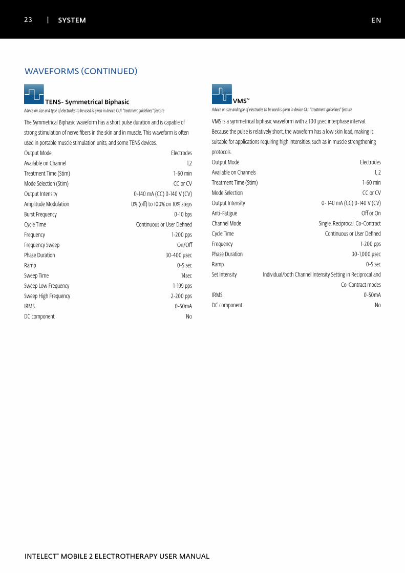
WAVEFORMS (CONTINUED)
TENS- Symmetrical BiphasicAdvice on size and type of electrodes to be used is given in device GUI "treatment guidelines" feature
The Symmetrical Biphasic waveform has a short pulse duration and is capable of
strong stimulation of nerve fibers in the skin and in muscle. This waveform is often
used in portable muscle stimulation units, and some TENS devices.
Output Mode Electrodes
Available on Channel 1,2
Treatment Time (Stim) 1-60 min
Mode Selection (Stim) CC or CV
Output Intensity 0-140 mA (CC) 0-140 V (CV)
Amplitude Modulation 0% (off) to 100% on 10% steps
Burst Frequency 0-10 bps
Cycle Time Continuous or User Defined
Frequency 1-200 pps
Frequency Sweep On/Off
Phase Duration 30-400 µsec
Ramp 0-5 sec
Sweep Time 14sec
Sweep Low Frequency 1-199 pps
Sweep High Frequency 2-200 pps
IRMS 0-50mA
DC component No
VMS™
Advice on size and type of electrodes to be used is given in device GUI "treatment guidelines" feature
VMS is a symmetrical biphasic waveform with a 100 µsec interphase interval.
Because the pulse is relatively short, the waveform has a low skin load, making it
suitable for applications requiring high intensities, such as in muscle strengthening
protocols.
Output Mode Electrodes
Available on Channels 1, 2
Treatment Time (Stim) 1-60 min
Mode Selection CC or CV
Output Intensity 0- 140 mA (CC) 0-140 V (CV)
Anti-Fatigue Off or On
Channel Mode Single, Reciprocal, Co-Contract
Cycle Time Continuous or User Defined
Frequency 1-200 pps
Phase Duration 30-1,000 µsec
Ramp 0-5 sec
Set Intensity Individual/both Channel Intensity Setting in Reciprocal and
Co-Contract modes
IRMS 0-50mA
DC component No
24 SYSTEM EN
INTELECT® MOBILE 2 ELECTROTHERAPY USER MANUAL
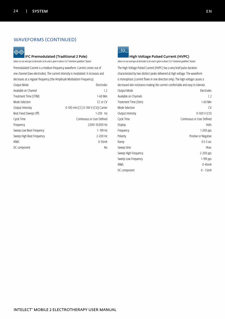
IFC Premodulated (Traditional 2 Pole)Advice on size and type of electrodes to be used is given in device GUI "treatment guidelines" feature
Premodulated Current is a medium frequency waveform. Current comes out of
one channel (two electrodes). The current intensity is modulated: it increases and
decreases at a regular frequency (the Amplitude Modulation Frequency).
Output Mode Electrodes
Available on Channel 1, 2
Treatment Time (STIM) 1-60 Min
Mode Selection CC or CV
Output Intensity 0-100 mA (CC) 0-100 V (CV)) Carrier
Beat Fixed (Sweep Off) 1-200 Hz
Cycle Time Continuous or User Defined
Frequency 2,000-10,000 Hz
Sweep Low Beat Frequency 1- 199 Hz
Sweep High Beat Frequency 2-200 Hz
IRMS 0-55mA
DC component No
WAVEFORMS (CONTINUED)
High Voltage Pulsed Current (HVPC)Advice on size and type of electrodes to be used is given in device GUI "treatment guidelines" feature
The High Voltage Pulsed Current (HVPC) has a very brief pulse duration
characterized by two distinct peaks delivered at high voltage. The waveform
is monophasic (current flows in one direction only). The high voltage causes a
decreased skin resistance making the current comfortable and easy to tolerate.
Output Mode Electrodes
Available on Channels 1, 2
Treatment Time (Stim) 1-60 Min
Mode Selection CV
Output Intensity 0-500 V (CV)
Cycle Time Continuous or User Defined
Display Volts
Frequency 1-200 pps
Polarity Positive or Negative
Ramp 0.5-5 sec
Sweep time 14sec
Sweep High Frequency 2-200 pps
Sweep Low Frequency 1-199 pps
IRMS 0-45mA
DC component 0 - 1.5mA

25 PATIENT PREPARATION EN
INTELECT® MOBILE 2 ELECTROTHERAPY USER MANUAL
DURA-STICK® Electrode Instructions
Connecting Lead Wires1. Insert the lead with the Red (+) electrode connector into
one DURA-STICK® Electrode.
2. Insert the lead with the Black (-) electrode connector
into the other electrode.
3. Make certain the lead wires are seated completely into
the electrodes.
NOTE: Use of conductive medium or sponges is not required or recommended. DURA-STICK® electrodes are manufactured to ensure the optimum conductivity during therapy when properly applied.
Securing Electrodes1. Remove the DURA-STICK® Electrodes from the
protective backing.
2. Apply to the treatment area as prescribed.
3. Ensure the entire electrode surface is in contact with
patient skin by pressing into place.
• Examine the skin for any wounds and clean the skin.
• Apply the electrodes to the treatment area.
• Ensure the electrodes are applied securely to the skin.
• Ensure good contact between each electrode and the
skin.
• Check the electrode contact regularly during the
treatment.
• Examine the skin again after the treatment.
• Choose electrodes that fit the anatomy.
• View the Electrode Placement recommendations
in the Treatment Review screen for the particular
modality being used for treatment as a reference
point only prior to administering treatment.
• Follow electrode manufacturer instructions.
• Please note the smaller the electrode size the higher
the current density.
DURA-STICK® ElectrodesDURA-STICK® Electrodes are a self adhesive, disposable
product designed specifically for use with Intelect® Mobile 2.
It is recommended that DURA-STICK® Electrodes be used
whenever possible to ensure the highest level of contact
with the treatment area and most uniform delivery of the
prescribed electrotherapy treatment.
For Electrotherapy operation refer to page 42
ELECTROTHERAPY PATIENT PREPARATION AND ELECTRODE PLACEMENT
26 PATIENT PREPARATION EN
INTELECT® MOBILE 2 ELECTROTHERAPY USER MANUAL
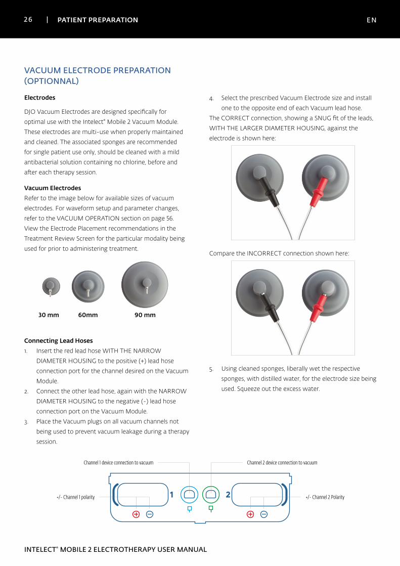
DJO Vacuum Electrodes are designed specifically for
optimal use with the Intelect® Mobile 2 Vacuum Module.
These electrodes are multi-use when properly maintained
and cleaned. The associated sponges are recommended
for single patient use only, should be cleaned with a mild
antibacterial solution containing no chlorine, before and
after each therapy session.
Vacuum ElectrodesRefer to the image below for available sizes of vacuum
electrodes. For waveform setup and parameter changes,
refer to the VACUUM OPERATION section on page 56.
View the Electrode Placement recommendations in the
Treatment Review Screen for the particular modality being
used for prior to administering treatment.
30 mm 60mm 90 mm
Connecting Lead Hoses1. Insert the red lead hose WITH THE NARROW
DIAMETER HOUSING to the positive (+) lead hose
connection port for the channel desired on the Vacuum
Module.
2. Connect the other lead hose, again with the NARROW
DIAMETER HOUSING to the negative (-) lead hose
connection port on the Vacuum Module.
3. Place the Vacuum plugs on all vacuum channels not
being used to prevent vacuum leakage during a therapy
session.
VACUUM ELECTRODE PREPARATION (OPTIONNAL)
Electrodes 4. Select the prescribed Vacuum Electrode size and install
one to the opposite end of each Vacuum lead hose.
The CORRECT connection, showing a SNUG fit of the leads,
WITH THE LARGER DIAMETER HOUSING, against the
electrode is shown here:
Compare the INCORRECT connection shown here:
5. Using cleaned sponges, liberally wet the respective
sponges, with distilled water, for the electrode size being
used. Squeeze out the excess water.
1 2
Channel 2 device connection to vacuumChannel 1 device connection to vacuum
+/- Channel 1 polarity +/- Channel 2 Polarity
27 PATIENT PREPARATION EN
INTELECT® MOBILE 2 ELECTROTHERAPY USER MANUAL
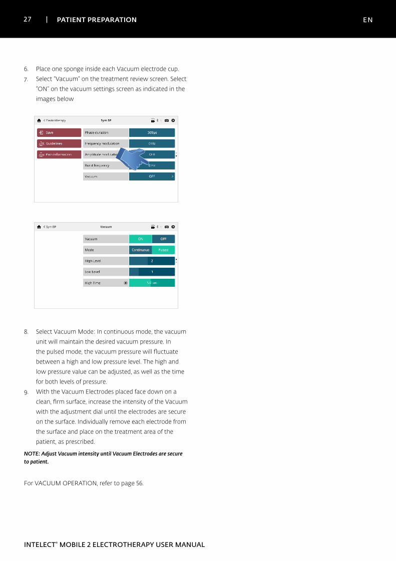
6. Place one sponge inside each Vacuum electrode cup.
7. Select “Vacuum” on the treatment review screen. Select
“ON” on the vacuum settings screen as indicated in the
images below
8. Select Vacuum Mode: In continuous mode, the vacuum
unit will maintain the desired vacuum pressure. In
the pulsed mode, the vacuum pressure will fluctuate
between a high and low pressure level. The high and
low pressure value can be adjusted, as well as the time
for both levels of pressure.
9. With the Vacuum Electrodes placed face down on a
clean, firm surface, increase the intensity of the Vacuum
with the adjustment dial until the electrodes are secure
on the surface. Individually remove each electrode from
the surface and place on the treatment area of the
patient, as prescribed.
NOTE: Adjust Vacuum intensity until Vacuum Electrodes are secure to patient.
For VACUUM OPERATION, refer to page 56.
28 USER INTERFACE EN
INTELECT® MOBILE 2 ELECTROTHERAPY USER MANUAL
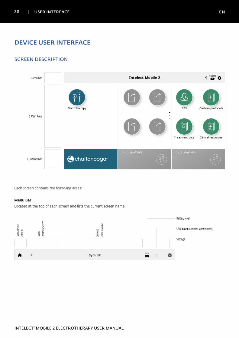
DEVICE USER INTERFACE
SCREEN DESCRIPTION
1. Menu Bar
2. Main Area
3. Channel Bar
Each screen contains the following areas:
Menu BarLocated at the top of each screen and lists the current screen name.
Go to
Hom
e Sc
reem
Go to
Pr
eviou
s Scre
en
Curre
nt
Scre
en N
ame
Battery level
USB (Black connected, Grey inacctive)
Settings
29 USER INTERFACE EN
INTELECT® MOBILE 2 ELECTROTHERAPY USER MANUAL
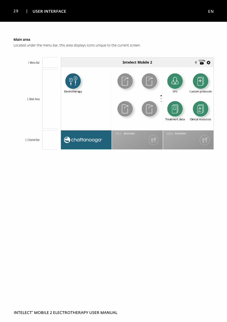
Main areaLocated under the menu bar, this area displays icons unique to the current screen.
1. Menu Bar
2. Main Area
3. Channel Bar
30 USER INTERFACE EN
INTELECT® MOBILE 2 ELECTROTHERAPY USER MANUAL
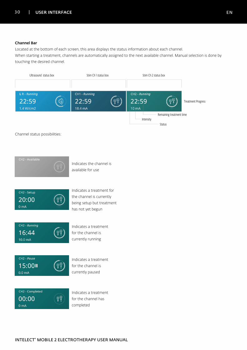
Channel BarLocated at the bottom of each screen, this area displays the status information about each channel.
When starting a treatment, channels are automatically assigned to the next available channel. Manual selection is done by
touching the desired channel.
Ultrasound status box Stim Ch 1 status box Stim Ch 2 status box
IntensityRemaining treatment time
Treatment Progress
Status
Channel status possibilities:
Indicates the channel is
available for use
Indicates a treatment for
the channel is currently
being setup but treatment
has not yet begun
Indicates a treatment
for the channel is
currently running
Indicates a treatment
for the channel is
currently paused
Indicates a treatment
for the channel has
completed
31 USER INTERFACE EN
INTELECT® MOBILE 2 ELECTROTHERAPY USER MANUAL
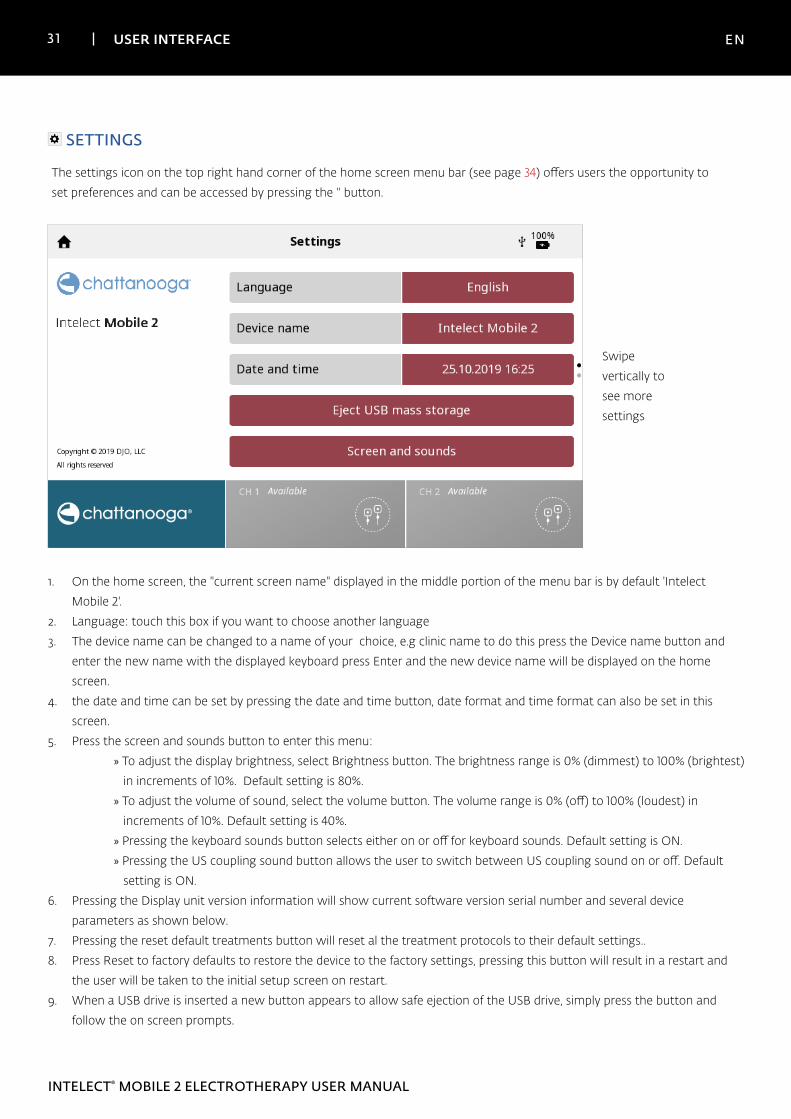
SETTINGS
The settings icon on the top right hand corner of the home screen menu bar (see page 34) offers users the opportunity to
set preferences and can be accessed by pressing the '' button.
Swipe
vertically to
see more
settings
1. On the home screen, the "current screen name" displayed in the middle portion of the menu bar is by default 'Intelect
Mobile 2'.
2. Language: touch this box if you want to choose another language
3. The device name can be changed to a name of your choice, e.g clinic name to do this press the Device name button and
enter the new name with the displayed keyboard press Enter and the new device name will be displayed on the home
screen.
4. the date and time can be set by pressing the date and time button, date format and time format can also be set in this
screen.
5. Press the screen and sounds button to enter this menu:
» To adjust the display brightness, select Brightness button. The brightness range is 0% (dimmest) to 100% (brightest)
in increments of 10%. Default setting is 80%.
» To adjust the volume of sound, select the volume button. The volume range is 0% (off) to 100% (loudest) in
increments of 10%. Default setting is 40%.
» Pressing the keyboard sounds button selects either on or off for keyboard sounds. Default setting is ON.
» Pressing the US coupling sound button allows the user to switch between US coupling sound on or off. Default
setting is ON.
6. Pressing the Display unit version information will show current software version serial number and several device
parameters as shown below.
7. Pressing the reset default treatments button will reset al the treatment protocols to their default settings..
8. Press Reset to factory defaults to restore the device to the factory settings, pressing this button will result in a restart and
the user will be taken to the initial setup screen on restart.
9. When a USB drive is inserted a new button appears to allow safe ejection of the USB drive, simply press the button and
follow the on screen prompts.
32 USER INTERFACE EN
INTELECT® MOBILE 2 ELECTROTHERAPY USER MANUAL
PRINT SCREEN FUNCTION
The Intelect Mobile 2 device has a built in function allowing the user to print screen fro example to print a treatment session this
performed by:
» 1. insert USB drive into the USB port on the back of the Mobile 2 device
» 2. Press the play pause button and the On/Off button for around 1 second the screen will flash and the image is
captured on the USB drive.
» 3. in the setting menu eject the USB drive to enable safe removal from the Mobile 2 device.
» 4.The format of the file is a bitmap file and it is date & Time coded in the filename.
Note : The print screen function should not be used during treatment
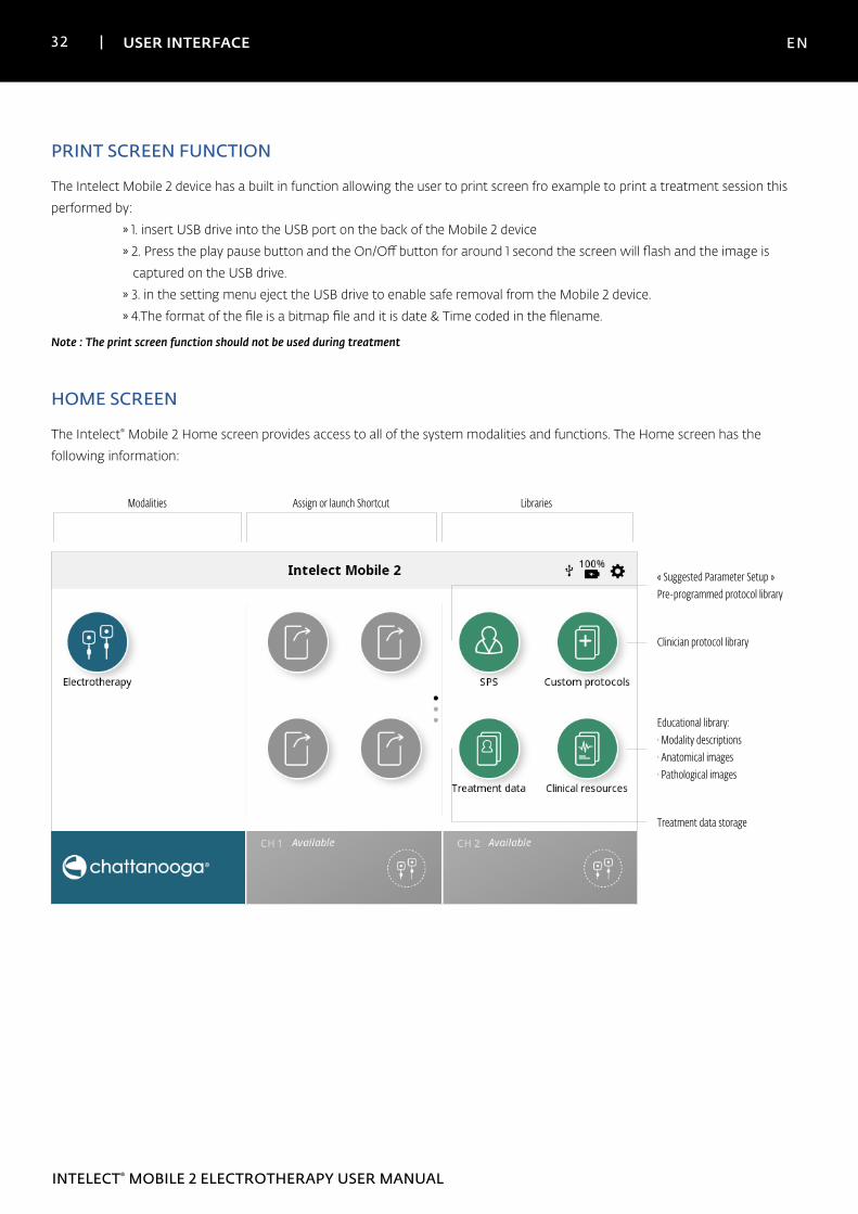
HOME SCREEN
The Intelect® Mobile 2 Home screen provides access to all of the system modalities and functions. The Home screen has the
following information:
Modalities Assign or launch Shortcut Libraries
Clinician protocol library
« Suggested Parameter Setup »Pre-programmed protocol library
Educational library:· Modality descriptions· Anatomical images· Pathological images
Treatment data storage
33 USER INTERFACE EN
INTELECT® MOBILE 2 ELECTROTHERAPY USER MANUAL
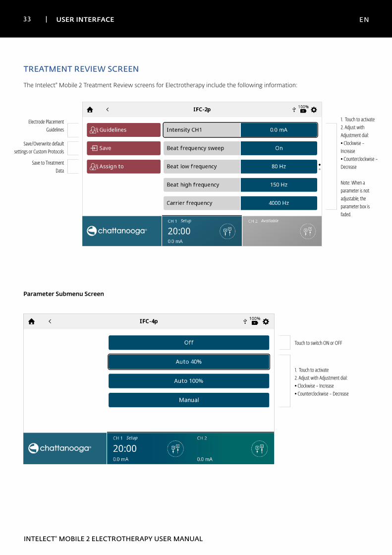
TREATMENT REVIEW SCREEN
The Intelect® Mobile 2 Treatment Review screens for Electrotherapy include the following information:
Electrode Placement Guidelines
Save/Overwrite default settings or Custom Protocols
1. Touch to activate2. Adjust with Adjustment dial:• Clockwise – Increase• Counterclockwise – Decrease
Note: When a parameter is not adjustable, the parameter box is faded.
Save to Treatment Data
Parameter Submenu Screen
Touch to switch ON or OFF
1. Touch to activate2. Adjust with Adjustment dial:• Clockwise – Increase• Counterclockwise – Decrease
34 USER INTERFACE EN
INTELECT® MOBILE 2 ELECTROTHERAPY USER MANUAL
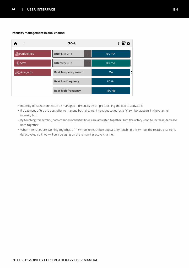
Intensity management in dual channel
• Intensity of each channel can be managed individually by simply touching the box to activate it
• If treatment offers the possibility to manage both channel intensities together, a "+" symbol appears in the channel
intensity box
• By touching this symbol, both channel intensities boxes are activated together. Turn the rotary knob to increase/decrease
both together
• When intensities are working together, a "-" symbol on each box appears. By touching this symbol the related channel is
desactivated so knob will only be aging on the remaining active channel.
35 USER INTERFACE EN
INTELECT® MOBILE 2 ELECTROTHERAPY USER MANUAL
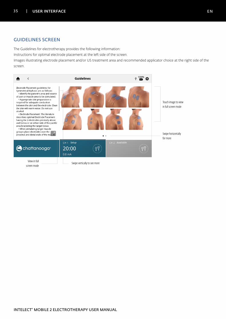
GUIDELINES SCREEN
The Guidelines for electrotherapy provides the following information:
Instructions for optimal electrode placement at the left side of the screen.
Images illustrating electrode placement and/or US treatment area and recommended applicator choice at the right side of the
screen.
Swipe vertically to see more
Touch image to view in full screen mode
View in full screen mode
Swipe horizontally for more
36 USER INTERFACE EN
INTELECT® MOBILE 2 ELECTROTHERAPY USER MANUAL
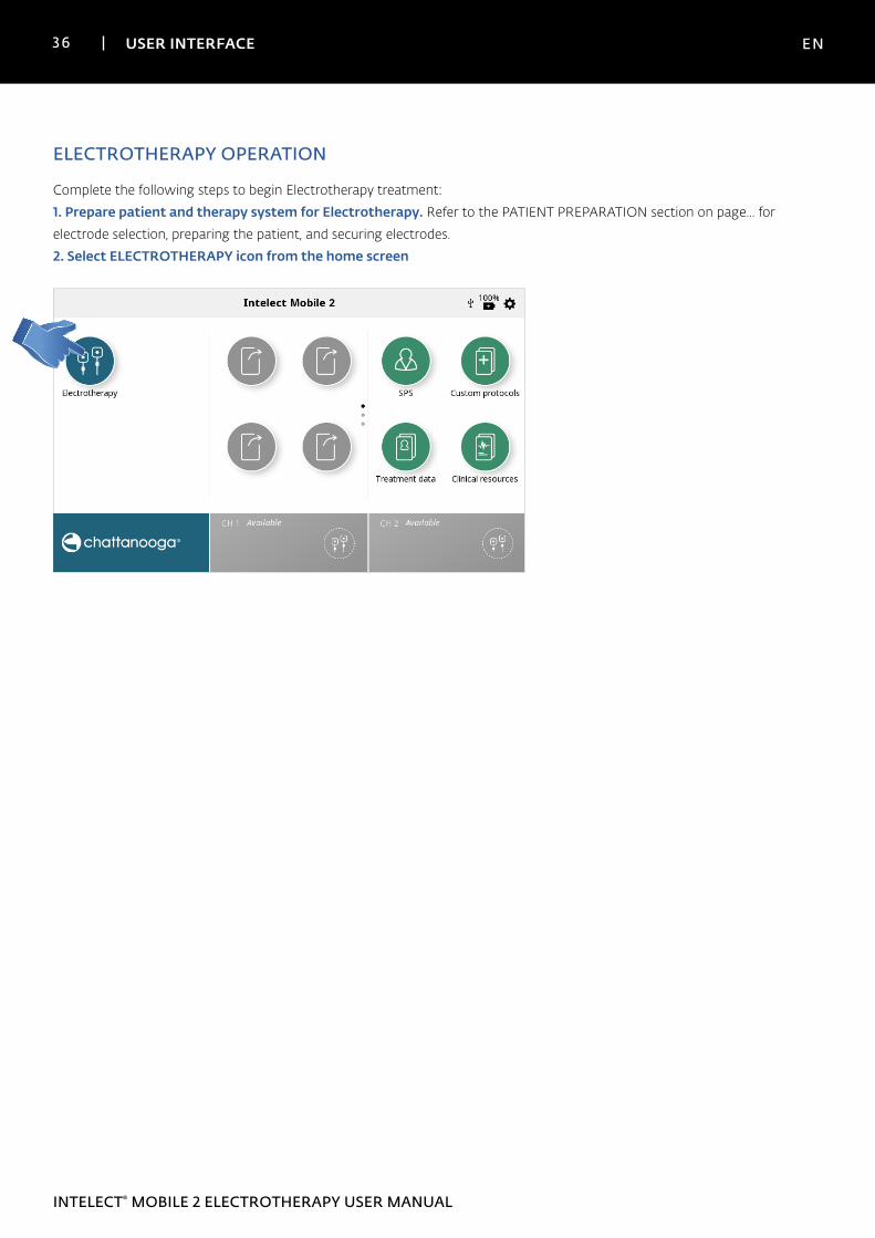
ELECTROTHERAPY OPERATION
Complete the following steps to begin Electrotherapy treatment:
1. Prepare patient and therapy system for Electrotherapy. Refer to the PATIENT PREPARATION section on page... for
electrode selection, preparing the patient, and securing electrodes.
2. Select ELECTROTHERAPY icon from the home screen
37 USER INTERFACE EN
INTELECT® MOBILE 2 ELECTROTHERAPY USER MANUAL
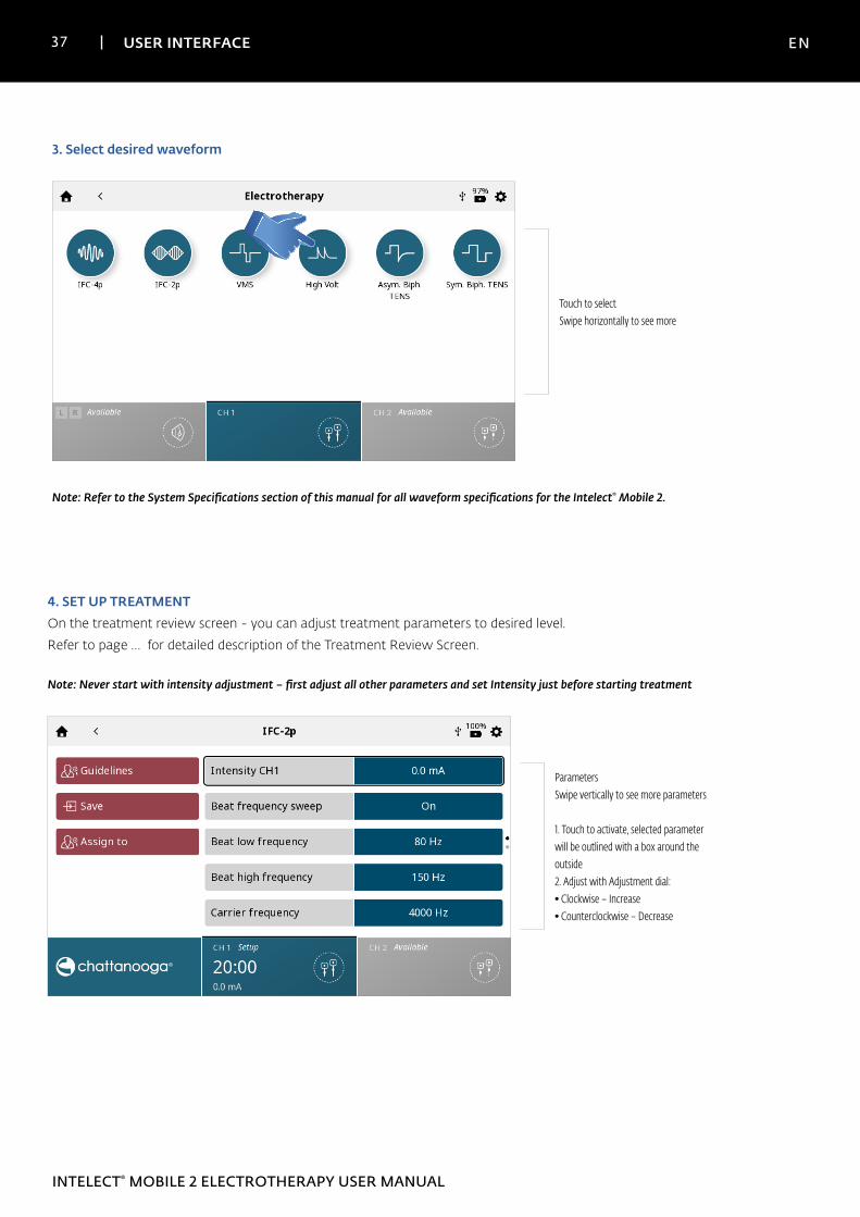
4. SET UP TREATMENT On the treatment review screen - you can adjust treatment parameters to desired level.
Refer to page … for detailed description of the Treatment Review Screen.
Note: Never start with intensity adjustment – first adjust all other parameters and set Intensity just before starting treatment
ParametersSwipe vertically to see more parameters
1. Touch to activate, selected parameter will be outlined with a box around the outside2. Adjust with Adjustment dial:• Clockwise – Increase• Counterclockwise – Decrease
3. Select desired waveform
Touch to selectSwipe horizontally to see more
Note: Refer to the System Specifications section of this manual for all waveform specifications for the Intelect® Mobile 2.
38 USER INTERFACE EN
INTELECT® MOBILE 2 ELECTROTHERAPY USER MANUAL
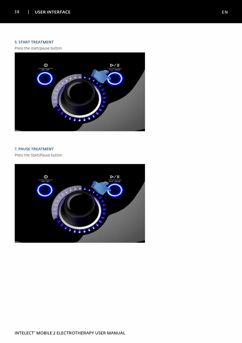
7. PAUSE TREATMENTPress the Start/Pause button
5. START TREATMENT Press the start/pause button
39 USER INTERFACE EN
INTELECT® MOBILE 2 ELECTROTHERAPY USER MANUAL
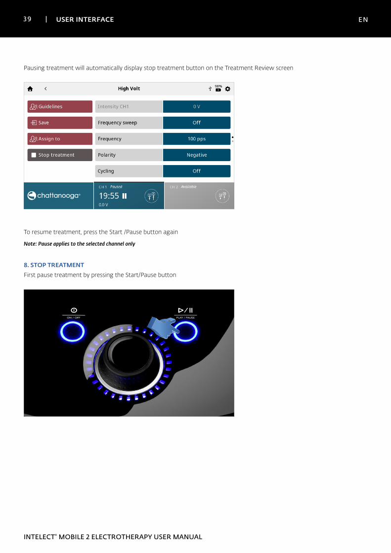
Pausing treatment will automatically display stop treatment button on the Treatment Review screen
To resume treatment, press the Start /Pause button again
Note: Pause applies to the selected channel only
8. STOP TREATMENTFirst pause treatment by pressing the Start/Pause button
40 USER INTERFACE EN
INTELECT® MOBILE 2 ELECTROTHERAPY USER MANUAL
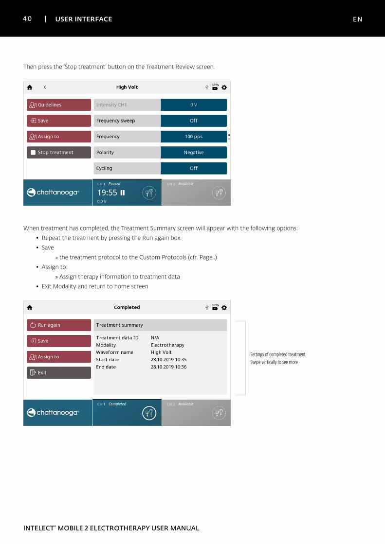
Then press the ‘Stop treatment‘ button on the Treatment Review screen.
When treatment has completed, the Treatment Summary screen will appear with the following options:
• Repeat the treatment by pressing the Run again box.
• Save
» the treatment protocol to the Custom Protocols (cfr. Page..)
• Assign to:
» Assign therapy information to treatment data
• Exit Modality and return to home screen
Settings of completed treatmentSwipe vertically to see more
41 USER INTERFACE EN
INTELECT® MOBILE 2 ELECTROTHERAPY USER MANUAL
VACUUM OPERATION
Complete the following steps to begin Electrotherapy with Vacuum treatment:
1. Prepare patient and therapy system for Vacuum Electrotherapy. Refer to the PATIENT PREPARATION section on page...
for electrode selection, preparing the patient, and securing electrodes.
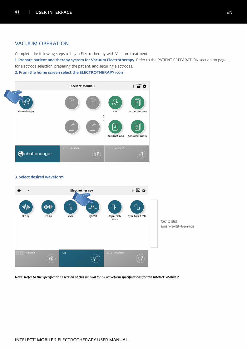
2. From the home screen select the ELECTROTHERAPY icon
3. Select desired waveform
Touch to selectSwipe horizontally to see more
Note: Refer to the Specifications section of this manual for all waveform specifications for the Intelect® Mobile 2.
42 USER INTERFACE EN
INTELECT® MOBILE 2 ELECTROTHERAPY USER MANUAL
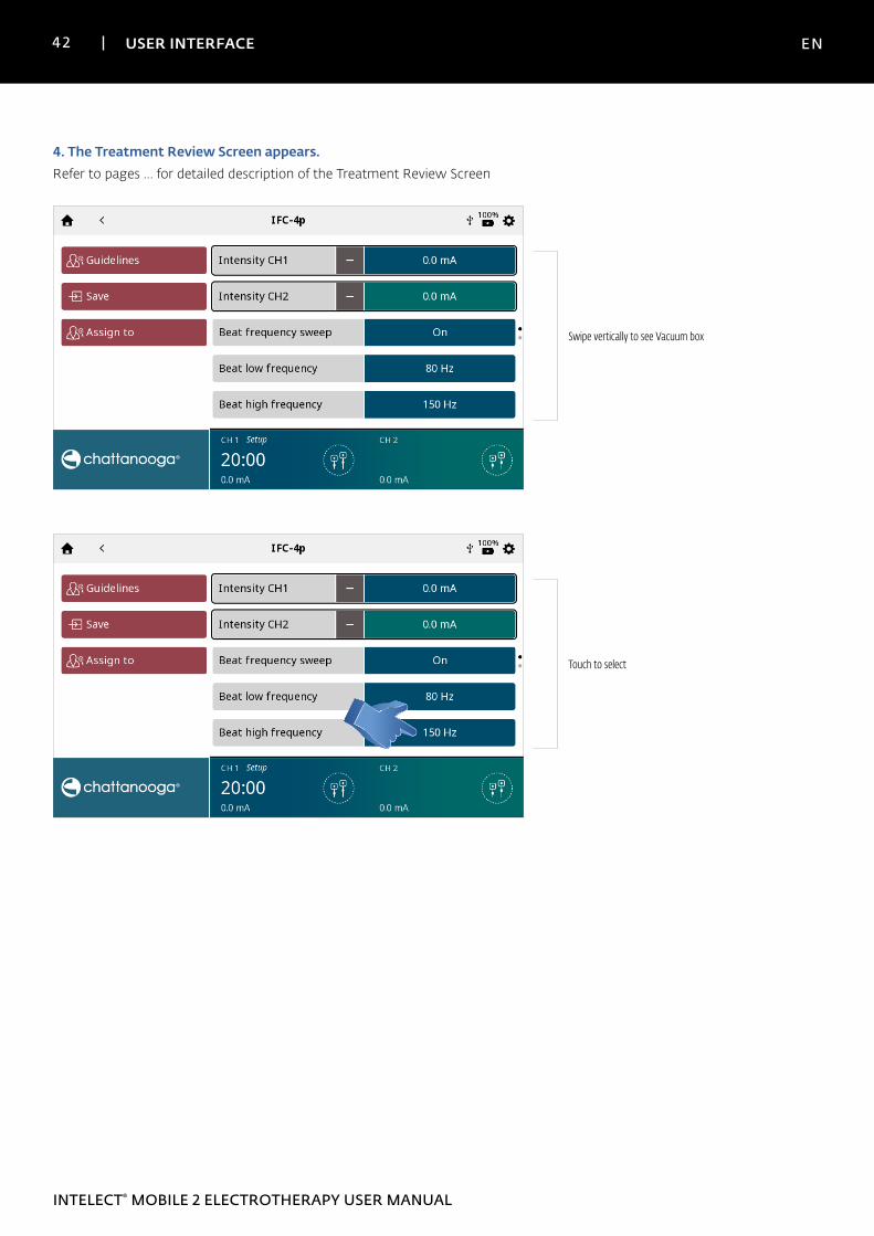
4. The Treatment Review Screen appears.Refer to pages … for detailed description of the Treatment Review Screen
Swipe vertically to see Vacuum box
Touch to select
43 USER INTERFACE EN
INTELECT® MOBILE 2 ELECTROTHERAPY USER MANUAL
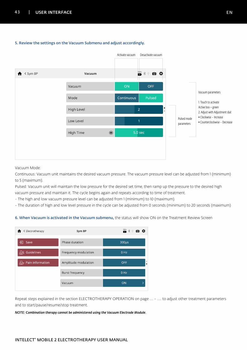
5. Review the settings on the Vacuum Submenu and adjust accordingly.
Activate vacuum
Vacuum parameters
1. Touch to activateActive box = green2. Adjust with Adjustment dial:• Clockwise – Increase• Counterclockwise – Decrease
Desactivate vacuum
Pulsed mode parameters
Vacuum Mode:
Continuous: Vacuum unit maintains the desired vacuum pressure. The vacuum pressure level can be adjusted from 1 (minimum)
to 5 (maximum).
Pulsed: Vacuum unit will maintain the low pressure for the desired set time, then ramp up the pressure to the desired high
vacuum pressure and maintain it. The cycle begins again and repeats according to time of treatment.
- The high and low vacuum pressure level can be adjusted from 1 (minimum) to 10 (maximum).
- The duration of high and low level pressure in the cycle can be adjusted from 0 seconds (minimum) to 20 seconds (maximum)
6. When Vacuum is activated in the Vacuum submenu, the status will show ON on the Treatment Review Screen
Repeat steps explained in the section ELECTROTHERAPY OPERATION on page …. - ….. to adjust other treatment parameters
and to start/pause/resume/stop treatment.
NOTE: Combination therapy cannot be administered using the Vacuum Electrode Module.
44 USER INTERFACE EN
INTELECT® MOBILE 2 ELECTROTHERAPY USER MANUAL
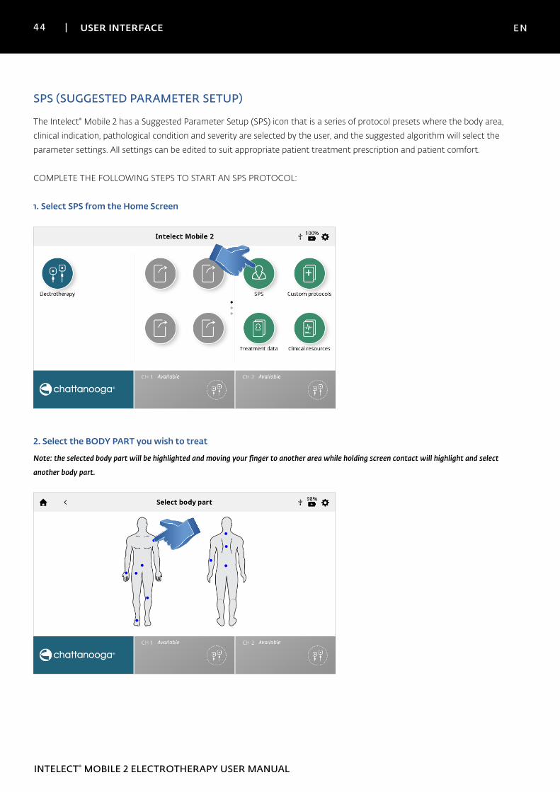
SPS (SUGGESTED PARAMETER SETUP)
The Intelect® Mobile 2 has a Suggested Parameter Setup (SPS) icon that is a series of protocol presets where the body area,
clinical indication, pathological condition and severity are selected by the user, and the suggested algorithm will select the
parameter settings. All settings can be edited to suit appropriate patient treatment prescription and patient comfort.
COMPLETE THE FOLLOWING STEPS TO START AN SPS PROTOCOL:
1. Select SPS from the Home Screen
2. Select the BODY PART you wish to treat
Note: the selected body part will be highlighted and moving your finger to another area while holding screen contact will highlight and select
another body part.
45 USER INTERFACE EN
INTELECT® MOBILE 2 ELECTROTHERAPY USER MANUAL
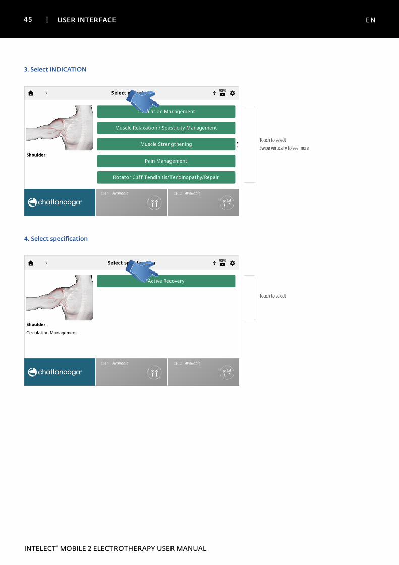
3. Select INDICATION
Touch to selectSwipe vertically to see more
4. Select specification
Touch to select
46 USER INTERFACE EN
INTELECT® MOBILE 2 ELECTROTHERAPY USER MANUAL
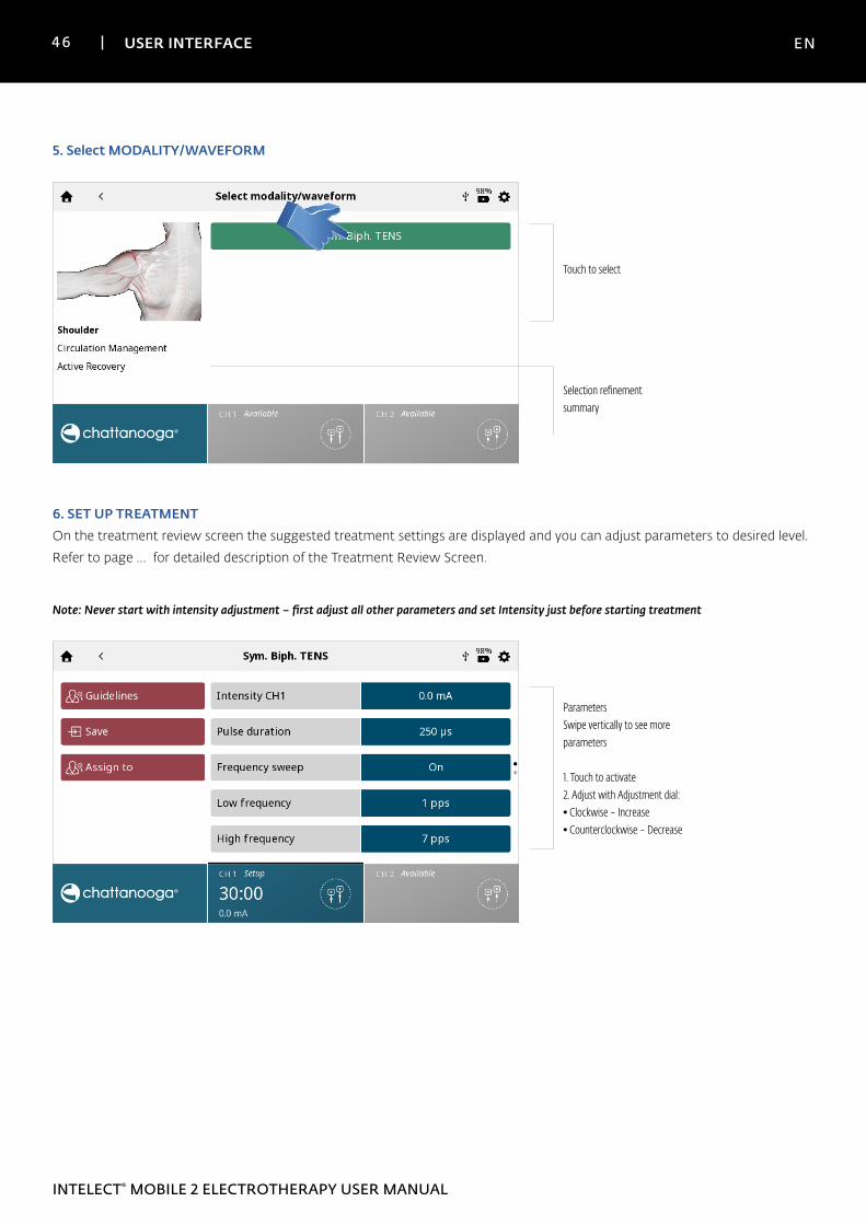
5. Select MODALITY/WAVEFORM
Touch to select
Selection refinement summary
6. SET UP TREATMENTOn the treatment review screen the suggested treatment settings are displayed and you can adjust parameters to desired level.
Refer to page … for detailed description of the Treatment Review Screen.
Note: Never start with intensity adjustment – first adjust all other parameters and set Intensity just before starting treatment
ParametersSwipe vertically to see more parameters
1. Touch to activate2. Adjust with Adjustment dial:• Clockwise – Increase• Counterclockwise – Decrease
47 USER INTERFACE EN
INTELECT® MOBILE 2 ELECTROTHERAPY USER MANUAL
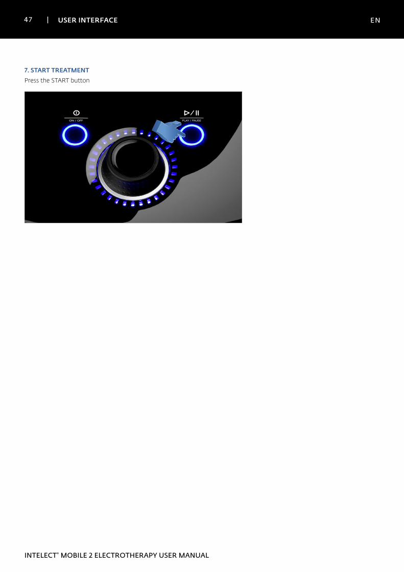
7. START TREATMENTPress the START button
48 USER INTERFACE EN
INTELECT® MOBILE 2 ELECTROTHERAPY USER MANUAL
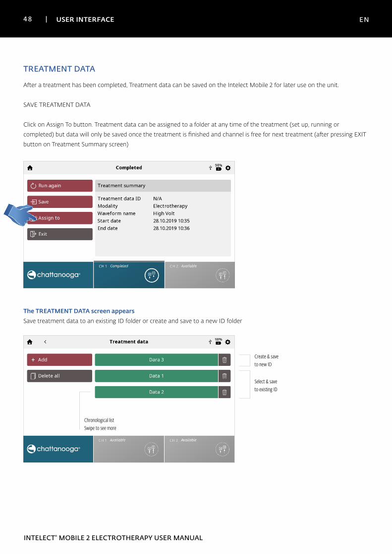
TREATMENT DATA
After a treatment has been completed, Treatment data can be saved on the Intelect Mobile 2 for later use on the unit.
SAVE TREATMENT DATA
Click on Assign To button. Treatment data can be assigned to a folder at any time of the treatment (set up, running or
completed) but data will only be saved once the treatment is finished and channel is free for next treatment (after pressing EXIT
button on Treatment Summary screen)
The TREATMENT DATA screen appearsSave treatment data to an existing ID folder or create and save to a new ID folder
Select & save to existing ID
Create & save to new ID
Chronological listSwipe to see more
49 USER INTERFACE EN
INTELECT® MOBILE 2 ELECTROTHERAPY USER MANUAL
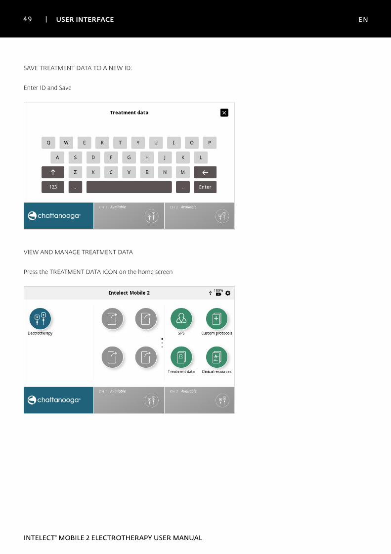
SAVE TREATMENT DATA TO A NEW ID:
Enter ID and Save
VIEW AND MANAGE TREATMENT DATA
Press the TREATMENT DATA ICON on the home screen
50 USER INTERFACE EN
INTELECT® MOBILE 2 ELECTROTHERAPY USER MANUAL
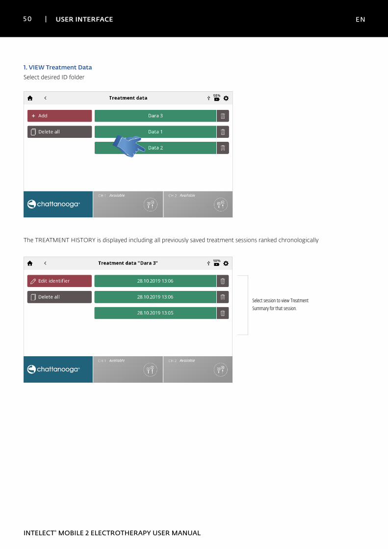
1. VIEW Treatment Data Select desired ID folder
The TREATMENT HISTORY is displayed including all previously saved treatment sessions ranked chronologically
Select session to view Treatment Summary for that session.
51 USER INTERFACE EN
INTELECT® MOBILE 2 ELECTROTHERAPY USER MANUAL
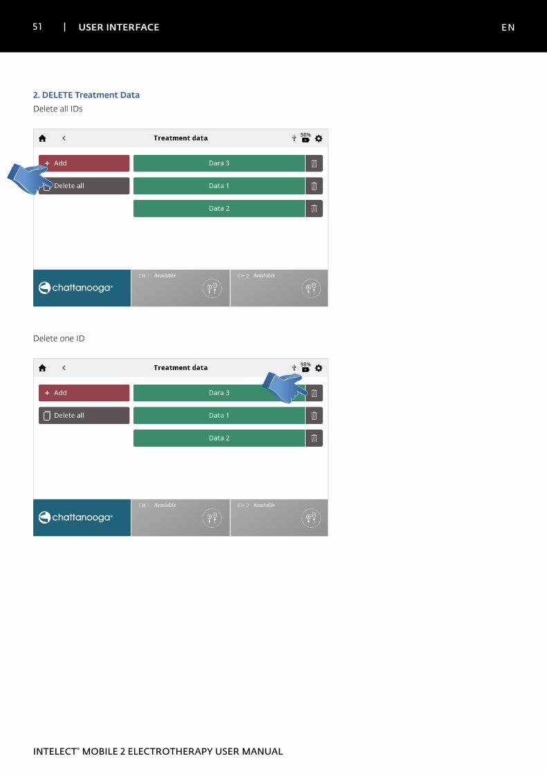
2. DELETE Treatment DataDelete all IDs
Delete one ID
52 USER INTERFACE EN
INTELECT® MOBILE 2 ELECTROTHERAPY USER MANUAL
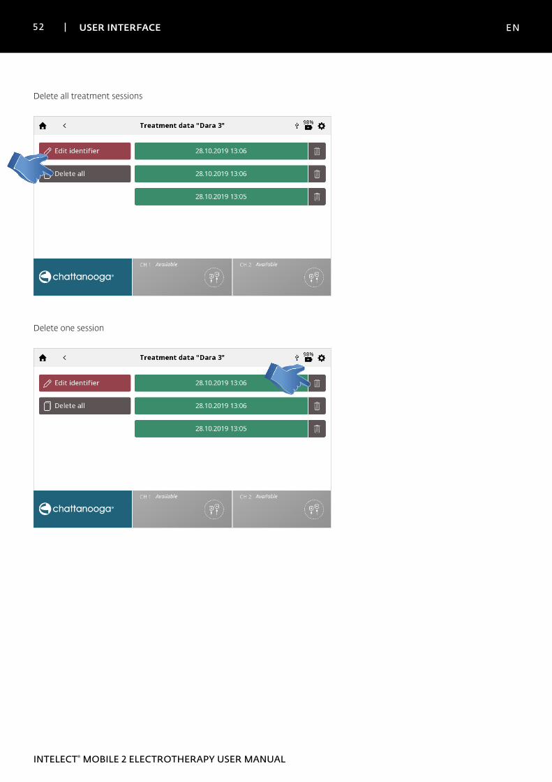
Delete all treatment sessions
Delete one session
53 USER INTERFACE EN
INTELECT® MOBILE 2 ELECTROTHERAPY USER MANUAL
CUSTOM PROTOCOLS
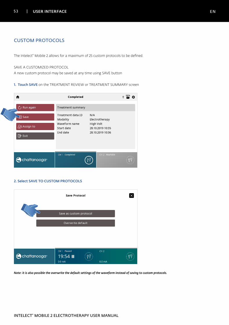
The Intelect® Mobile 2 allows for a maximum of 25 custom protocols to be defined.
SAVE A CUSTOMIZED PROTOCOL
A new custom protocol may be saved at any time using SAVE button
1. Touch SAVE on the TREATMENT REVIEW or TREATMENT SUMMARY screen
2. Select SAVE TO CUSTOM PROTOCOLS
Note: it is also possible the overwrite the default settings of the waveform instead of saving to custom protocols.
54 USER INTERFACE EN
INTELECT® MOBILE 2 ELECTROTHERAPY USER MANUAL
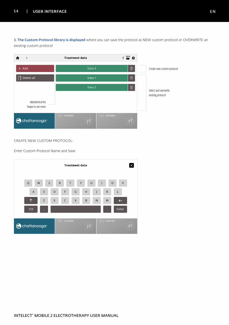
3. The Custom Protocol library is displayed where you can save the protocol as NEW custom protocol or OVERWRITE an
existing custom protocol
Select and overwrite existing protocol
Create new custom protocol
Alphabetical listSwipe to see more
CREATE NEW CUSTOM PROTOCOL:
Enter Custom Protocol Name and Save
55 USER INTERFACE EN
INTELECT® MOBILE 2 ELECTROTHERAPY USER MANUAL
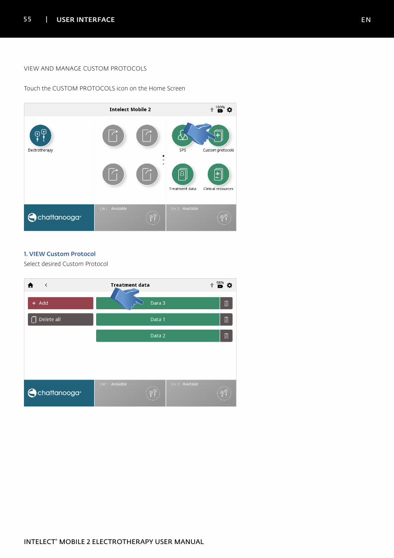
VIEW AND MANAGE CUSTOM PROTOCOLS
Touch the CUSTOM PROTOCOLS icon on the Home Screen
1. VIEW Custom ProtocolSelect desired Custom Protocol
56 USER INTERFACE EN
INTELECT® MOBILE 2 ELECTROTHERAPY USER MANUAL
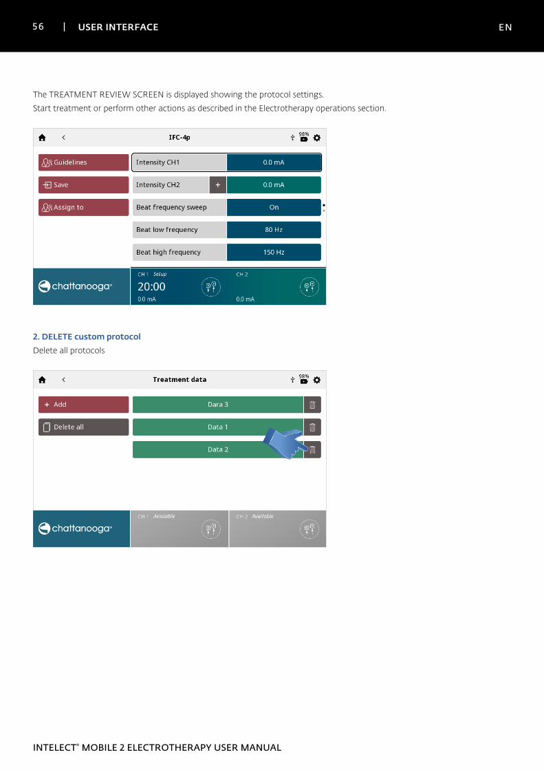
The TREATMENT REVIEW SCREEN is displayed showing the protocol settings.
Start treatment or perform other actions as described in the Electrotherapy operations section.
2. DELETE custom protocolDelete all protocols
57 USER INTERFACE EN
INTELECT® MOBILE 2 ELECTROTHERAPY USER MANUAL
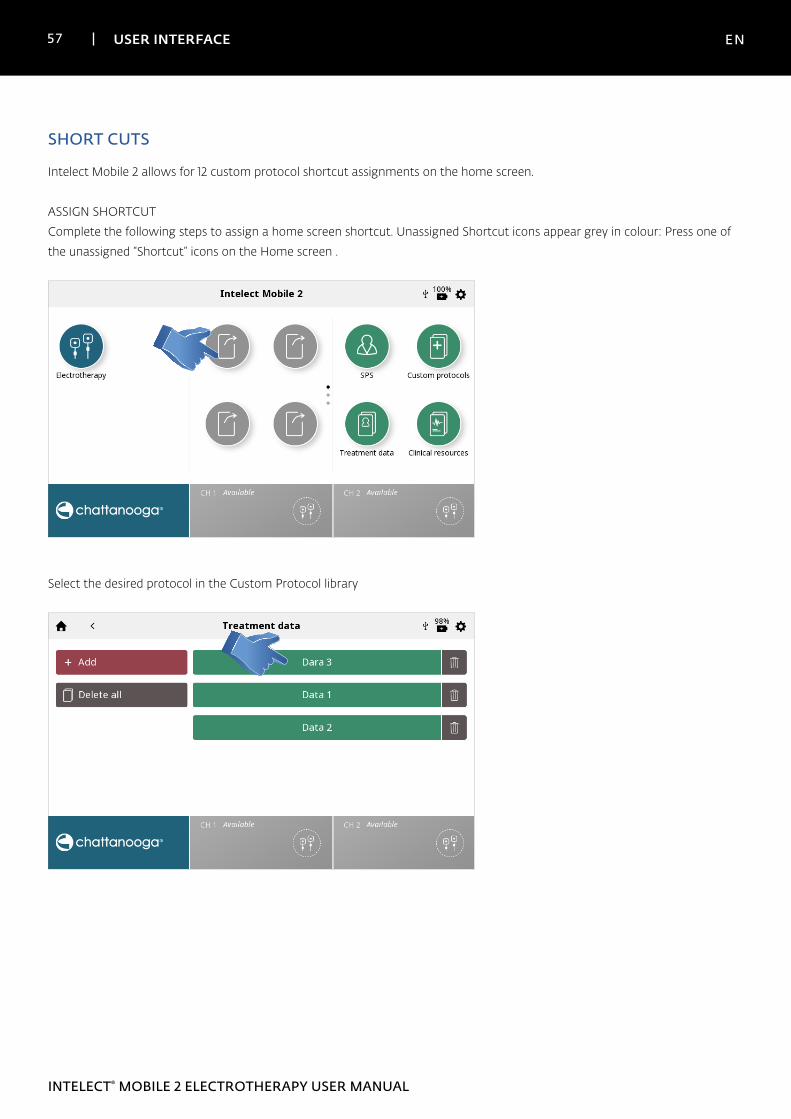
SHORT CUTS
Intelect Mobile 2 allows for 12 custom protocol shortcut assignments on the home screen.
ASSIGN SHORTCUT
Complete the following steps to assign a home screen shortcut. Unassigned Shortcut icons appear grey in colour: Press one of
the unassigned “Shortcut” icons on the Home screen .
Select the desired protocol in the Custom Protocol library
58 USER INTERFACE EN
INTELECT® MOBILE 2 ELECTROTHERAPY USER MANUAL
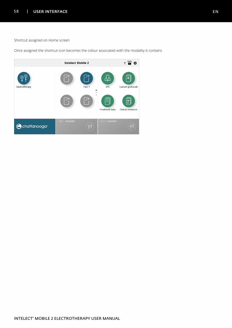
Shortcut assigned on Home screen
Once assigned the shortcut icon becomes the colour associated with the modality it contains
59 USER INTERFACE EN
INTELECT® MOBILE 2 ELECTROTHERAPY USER MANUAL
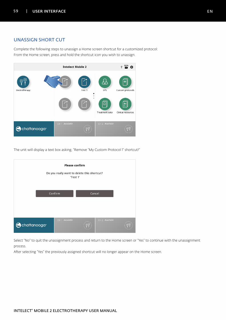
UNASSIGN SHORT CUT
Complete the following steps to unassign a Home screen shortcut for a customized protocol:
From the Home screen, press and hold the shortcut icon you wish to unassign.
The unit will display a text box asking, “Remove “My Custom Protocol 1” shortcut?”
Select “No” to quit the unassignment process and return to the Home screen or “Yes” to continue with the unassignment
process.
After selecting “Yes” the previously assigned shortcut will no longer appear on the Home screen.
60 USER INTERFACE EN
INTELECT® MOBILE 2 ELECTROTHERAPY USER MANUAL
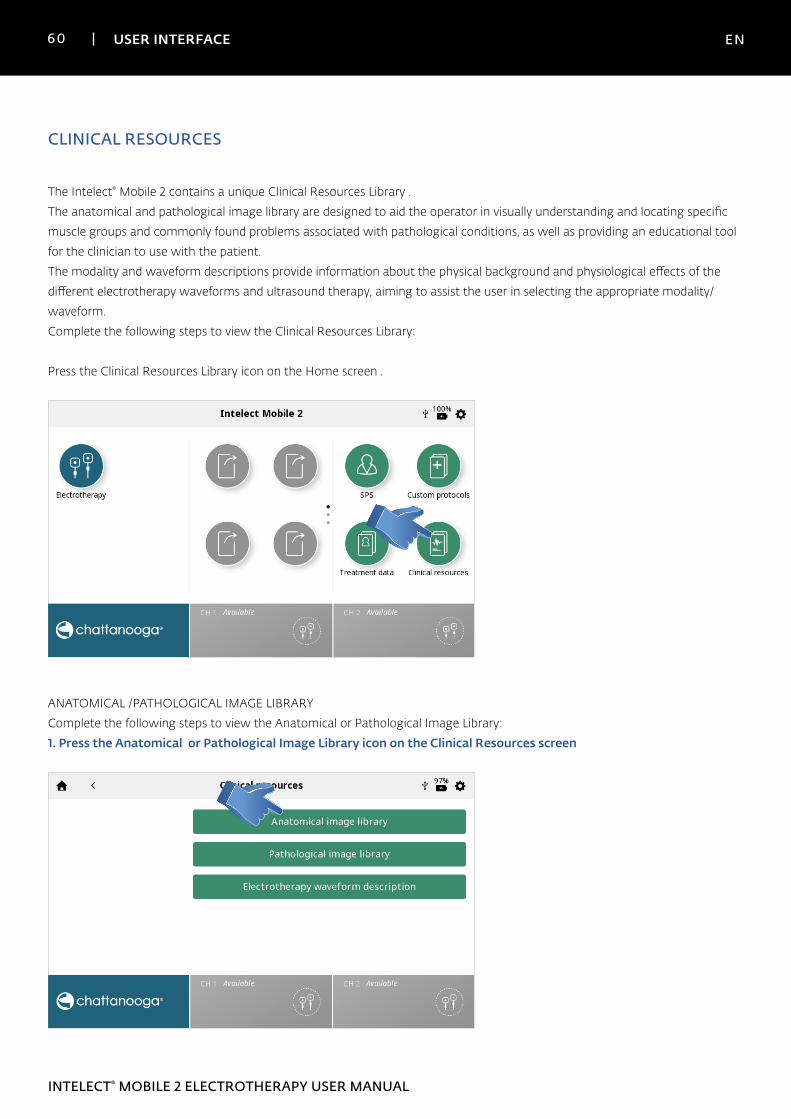
CLINICAL RESOURCES
The Intelect® Mobile 2 contains a unique Clinical Resources Library .
The anatomical and pathological image library are designed to aid the operator in visually understanding and locating specific
muscle groups and commonly found problems associated with pathological conditions, as well as providing an educational tool
for the clinician to use with the patient.
The modality and waveform descriptions provide information about the physical background and physiological effects of the
different electrotherapy waveforms and ultrasound therapy, aiming to assist the user in selecting the appropriate modality/
waveform.
Complete the following steps to view the Clinical Resources Library:
Press the Clinical Resources Library icon on the Home screen .
ANATOMICAL /PATHOLOGICAL IMAGE LIBRARY
Complete the following steps to view the Anatomical or Pathological Image Library:
1. Press the Anatomical or Pathological Image Library icon on the Clinical Resources screen
61 USER INTERFACE EN
INTELECT® MOBILE 2 ELECTROTHERAPY USER MANUAL
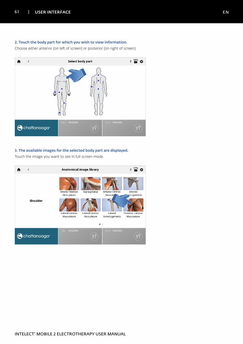
2. Touch the body part for which you wish to view information. Choose either anterior (on left of screen) or posterior (on right of screen).
3. The available images for the selected body part are displayed.Touch the image you want to see in full screen mode.
62 USER INTERFACE EN
INTELECT® MOBILE 2 ELECTROTHERAPY USER MANUAL
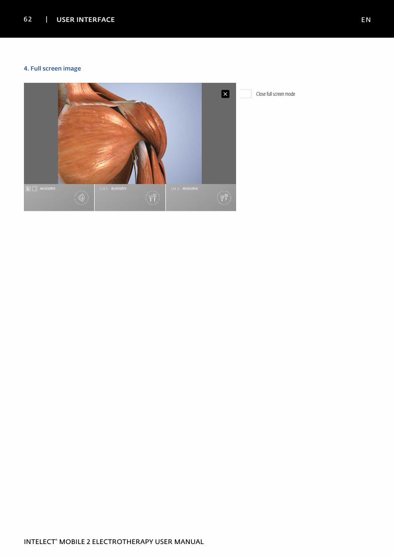
4. Full screen image
Close full screen mode
63 USER INTERFACE EN
INTELECT® MOBILE 2 ELECTROTHERAPY USER MANUAL
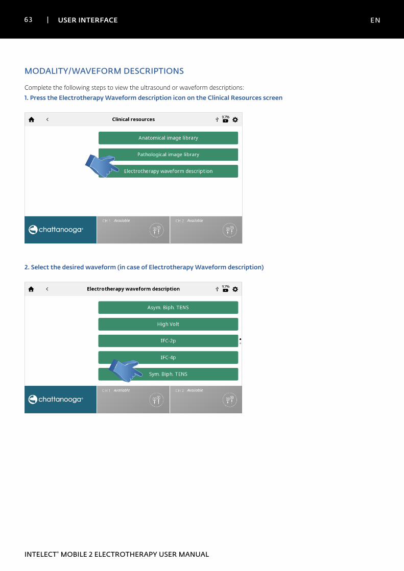
MODALITY/WAVEFORM DESCRIPTIONS
Complete the following steps to view the ultrasound or waveform descriptions:
1. Press the Electrotherapy Waveform description icon on the Clinical Resources screen
2. Select the desired waveform (in case of Electrotherapy Waveform description)
64 USER INTERFACE EN
INTELECT® MOBILE 2 ELECTROTHERAPY USER MANUAL
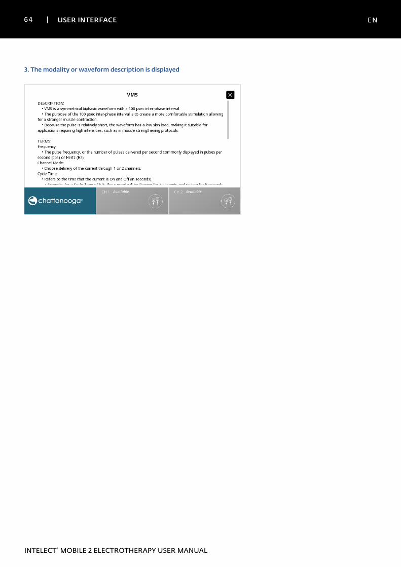
3. The modality or waveform description is displayed
65 TROUBLESHOOTING EN
INTELECT® MOBILE 2 ELECTROTHERAPY USER MANUAL
TROUBLESHOOTING
1. All system messages, warning messages and fault messages that are generated by the device are self-explanatory excepting
system error.
2. If System error occurs, note error code and contact DJO selling dealer or DJO Service Department.
66 ACCESSORIES EN
INTELECT® MOBILE 2 ELECTROTHERAPY USER MANUAL
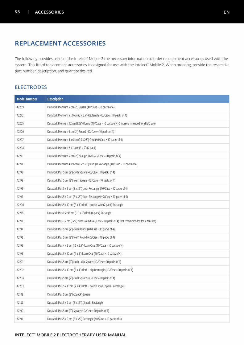
REPLACEMENT ACCESSORIES
The following provides users of the Intelect® Mobile 2 the necessary information to order replacement accessories used with the
system. This list of replacement accessories is designed for use with the Intelect® Mobile 2. When ordering, provide the respective
part number, description, and quantity desired.
ELECTRODES
Model Number Description
42209 Durastick Premium 5 cm (2”) Square (40/Case = 10 packs of 4)
42210 Durastick Premium 5 x 9 cm (2 x 3.5”) Rectangle (40/Case = 10 packs of 4)
42205 Durastick Premium 3.2 cm (1.25”) Round (40/Case = 10 packs of 4) (not recommended for sEMG use)
42206 Durastick Premium 5 cm (2”) Round (40/Case = 10 packs of 4)
42207 Durastick Premium 4 x 6 cm (1.5 x 2.5”) Oval (40/Case = 10 packs of 4)
42208 Durastick Premium 8 x 13 cm (3 x 5”) (2 pack)
42211 Durastick Premium 5 cm (2”) blue gel Oval (40/Case = 10 packs of 4)
42212 Durastick Premium 4 x 9 cm (1.5 x 3.5”) blue gel Rectangle (40/Case = 10 packs of 4)
42198 Durastick Plus 5 cm (2”) cloth Square (40/Case = 10 packs of 4)
42193 Durastick Plus 5 cm (2”) foam Square (40/Case = 10 packs of 4)
42199 Durastick Plus 5 x 9 cm (2 x 3.5”) cloth Rectangle (40/Case = 10 packs of 4)
42194 Durastick Plus 5 x 9 cm (2 x 3.5”) foam Rectangle (40/Case = 10 packs of 4)
42200 Durastick Plus 5 x 10 cm (2 x 4”) cloth - double wire (2 pack) Rectangle
42218 Durastick Plus 1.5 x 15 cm (0.5 x 6”) cloth (6 pack) Rectangle
42219 Durastick Plus 3.2 cm (1.25”) cloth Round (40/Case = 10 packs of 4) (not recommended for sEMG use)
42197 Durastick Plus 5 cm (2”) cloth Round (40/Case = 10 packs of 4)
42192 Durastick Plus 5 cm (2”) foam Round (40/Case = 10 packs of 4)
42195 Durastick Plus 4 x 6 cm (1.5 x 2.5”) foam Oval (40/Case = 10 packs of 4)
42196 Durastick Plus 5 x 10 cm (2 x 4”) foam Oval (40/Case = 10 packs of 4)
42201 Durastick Plus 5 cm (2”) cloth - clip Square (40/Case = 10 packs of 4)
42202 Durastick Plus 5 x 10 cm (2 x 4”) cloth - clip Rectangle (40/Case = 10 packs of 4)
42204 Durastick Plus 5 cm (2”) cloth Square (40/Case = 10 packs of 4)
42203 Durastick Plus 5 x 10 cm (2 x 4”) cloth - double snap (2 pack) Rectangle
42188 Durastick Plus 5 cm (2”) (2 pack) Square
42189 Durastick Plus 5 x 9 cm (2 x 3.5”) (2 pack) Rectangle
42190 Durastick Plus 5 cm (2”) Square (40/Case = 10 packs of 4)
42191 Durastick Plus 5 x 9 cm (2 x 3.5”) Rectangle (40/Case = 10 packs of 4)
67 ACCESSORIES EN
INTELECT® MOBILE 2 ELECTROTHERAPY USER MANUAL
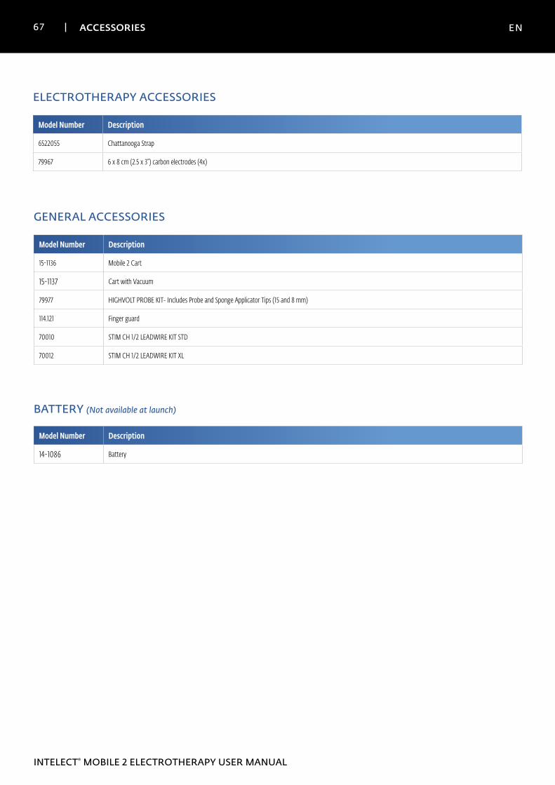
ELECTROTHERAPY ACCESSORIES
Model Number Description
6522055 Chattanooga Strap
79967 6 x 8 cm (2.5 x 3”) carbon electrodes (4x)
GENERAL ACCESSORIES
Model Number Description
15-1136 Mobile 2 Cart
15-1137 Cart with Vacuum
79977 HIGHVOLT PROBE KIT- Includes Probe and Sponge Applicator Tips (15 and 8 mm)
114.121 Finger guard
70010 STIM CH 1/2 LEADWIRE KIT STD
70012 STIM CH 1/2 LEADWIRE KIT XL
BATTERY (Not available at launch)
Model Number Description
14-1086 Battery
68 ACCESSORIES EN
INTELECT® MOBILE 2 ELECTROTHERAPY USER MANUAL
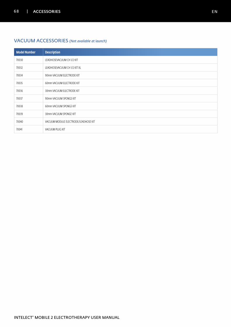
VACUUM ACCESSORIES (Not available at launch)
Model Number Description
70030 LEADHOSEVACUUM CH 1/2 KIT
70032 LEADHOSEVACUUM CH 1/2 KIT XL
70034 90mm VACUUM ELECTRODE KIT
70035 60mm VACUUM ELECTRODE KIT
70036 30mm VACUUM ELECTRODE KIT
70037 90mm VACUUM SPONGE KIT
70038 60mm VACUUM SPONGE KIT
70039 30mm VACUUM SPONGE KIT
70040 VACUUM MODULE ELECTRODE/LEADHOSE KIT
70041 VACUUM PLUG KIT
69 MAINTENANCE EN
INTELECT® MOBILE 2 ELECTROTHERAPY USER MANUAL
CLEANING THE INTELECT® MOBILE 2
With the system disconnected from the power source, clean
the system with a clean, lint-free cloth moistened with
water and mild antibacterial soap. If a more sterile cleaning
is needed, use a cloth moistened with an antimicrobial
cleaner. Cleaning should be performed daily.
Do not submerge the system in liquids. Should the unit
accidentally become submerged, contact the dealer or DJO
Service Department immediately.
Cleaning the LCD ScreenClean the LCD with a clean, dry cloth, in the same way as
cleaning the computer monitor screen. Do not use abrasive
materials or chemicals or liquids.
VACUUM MODULE CLEANING
Reservoir Draining• When draining the reservoir, wear surgical type
gloves. To drain the reservoir cup, rotate clockwise
direction, shown below. Dispose of contents in
accordance with your national, state or local disposal
guidelines.
Flushing Lead Hoses and Reservoir1. Connect all two lead hoses to the Vacuum Module.
Submerse the other end of the lead hoses into a
container filled with at least 250 ml (8 fl oz) of hot water
and one drop of dishwashing detergent added.
2. Turn Vacuum Module ON and set Vacuum Intensity to
maximum.
3. Repeat this procedure until no particles are visible when
the reservoir is drained.
4. Dispose of reservoir contents according to national,
state and local rules and regulations.
5. The Vacuum system should be flushed weekly.
Note: The vacuun system should be flushed and drained prior to vacuum module storage or transport if temperature could potentially
be below 0°C
Cleaning the Vacuum Module• With the system disconnected from the power
source, clean the vacuum module with a clean,
lint free cloth moistened with water and mild
antibacterial soap. If a more sterile cleaning is needed,
use a cloth moistened with an antimicrobial cleaner.
• Do not submerse the vacuum module in liquids.
Should the vacuum module accidentally become
submersed, contact the dealer or DJO Technical
Service Department immediately.
Cleaning Instructions for the Electrodes and Suction Cups
• A mild antibacterial solution containing no chlorine
can be administered with a cloth and wiped or
air dried. This is recommended between patient
treatments. These electrodes are multiuse when
properly maintained and cleaned.
Cleaning Instructions for the Sponges• The associated sponges are recommended for
single patient use only and should be cleaned with a
70% alcohol solution before and after each therapy
session.
70 MAINTENANCE EN
INTELECT® MOBILE 2 ELECTROTHERAPY USER MANUAL
CALIBRATION REQUIREMENTS
The unit was calibrated during the manufacturing process
and doesn't need calibration during the product life.
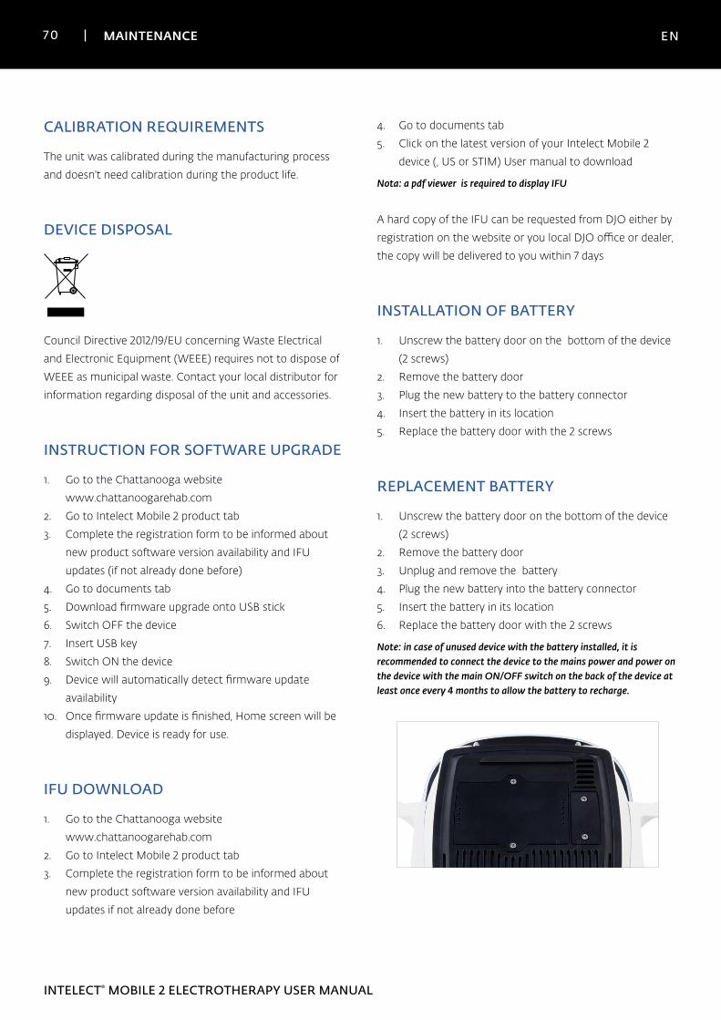
DEVICE DISPOSAL
Council Directive 2012/19/EU concerning Waste Electrical
and Electronic Equipment (WEEE) requires not to dispose of
WEEE as municipal waste. Contact your local distributor for
information regarding disposal of the unit and accessories.
INSTRUCTION FOR SOFTWARE UPGRADE
1. Go to the Chattanooga website
www.chattanoogarehab.com
2. Go to Intelect Mobile 2 product tab
3. Complete the registration form to be informed about
new product software version availability and IFU
updates (if not already done before)
4. Go to documents tab
5. Download firmware upgrade onto USB stick
6. Switch OFF the device
7. Insert USB key
8. Switch ON the device
9. Device will automatically detect firmware update
availability
10. Once firmware update is finished, Home screen will be
displayed. Device is ready for use.
IFU DOWNLOAD
1. Go to the Chattanooga website
www.chattanoogarehab.com
2. Go to Intelect Mobile 2 product tab
3. Complete the registration form to be informed about
new product software version availability and IFU
updates if not already done before
4. Go to documents tab
5. Click on the latest version of your Intelect Mobile 2
device (, US or STIM) User manual to download
Nota: a pdf viewer is required to display IFU
A hard copy of the IFU can be requested from DJO either by
registration on the website or you local DJO office or dealer,
the copy will be delivered to you within 7 days
INSTALLATION OF BATTERY
1. Unscrew the battery door on the bottom of the device
(2 screws)
2. Remove the battery door
3. Plug the new battery to the battery connector
4. Insert the battery in its location
5. Replace the battery door with the 2 screws
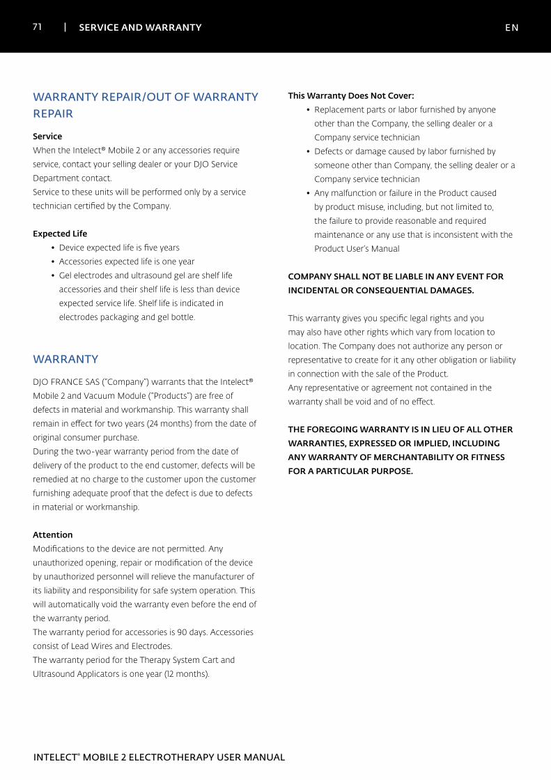
REPLACEMENT BATTERY
1. Unscrew the battery door on the bottom of the device
(2 screws)
2. Remove the battery door
3. Unplug and remove the battery
4. Plug the new battery into the battery connector
5. Insert the battery in its location
6. Replace the battery door with the 2 screws
Note: in case of unused device with the battery installed, it is recommended to connect the device to the mains power and power on the device with the main ON/OFF switch on the back of the device at least once every 4 months to allow the battery to recharge.
71 SERVICE AND WARRANTY EN
INTELECT® MOBILE 2 ELECTROTHERAPY USER MANUAL
WARRANTY REPAIR/OUT OF WARRANTY REPAIR
Service
When the Intelect® Mobile 2 or any accessories require
service, contact your selling dealer or your DJO Service
Department contact.
Service to these units will be performed only by a service
technician certified by the Company.
Expected Life• Device expected life is five years
• Accessories expected life is one year
• Gel electrodes and ultrasound gel are shelf life
accessories and their shelf life is less than device
expected service life. Shelf life is indicated in
electrodes packaging and gel bottle.
WARRANTY
DJO FRANCE SAS (“Company”) warrants that the Intelect®
Mobile 2 and Vacuum Module (“Products”) are free of
defects in material and workmanship. This warranty shall
remain in effect for two years (24 months) from the date of
original consumer purchase.
During the two-year warranty period from the date of
delivery of the product to the end customer, defects will be
remedied at no charge to the customer upon the customer
furnishing adequate proof that the defect is due to defects
in material or workmanship.
AttentionModifications to the device are not permitted. Any
unauthorized opening, repair or modification of the device
by unauthorized personnel will relieve the manufacturer of
its liability and responsibility for safe system operation. This
will automatically void the warranty even before the end of
the warranty period.
The warranty period for accessories is 90 days. Accessories
consist of Lead Wires and Electrodes.
The warranty period for the Therapy System Cart and
Ultrasound Applicators is one year (12 months).
This Warranty Does Not Cover:• Replacement parts or labor furnished by anyone
other than the Company, the selling dealer or a
Company service technician
• Defects or damage caused by labor furnished by
someone other than Company, the selling dealer or a
Company service technician
• Any malfunction or failure in the Product caused
by product misuse, including, but not limited to,
the failure to provide reasonable and required
maintenance or any use that is inconsistent with the
Product User’s Manual
COMPANY SHALL NOT BE LIABLE IN ANY EVENT FOR INCIDENTAL OR CONSEQUENTIAL DAMAGES.
This warranty gives you specific legal rights and you
may also have other rights which vary from location to
location. The Company does not authorize any person or
representative to create for it any other obligation or liability
in connection with the sale of the Product.
Any representative or agreement not contained in the
warranty shall be void and of no effect.
THE FOREGOING WARRANTY IS IN LIEU OF ALL OTHER WARRANTIES, EXPRESSED OR IMPLIED, INCLUDING ANY WARRANTY OF MERCHANTABILITY OR FITNESS FOR A PARTICULAR PURPOSE.
72 APPENDIX EN
INTELECT® MOBILE 2 ELECTROTHERAPY USER MANUAL
ELECTROMAGNETIC COMPATIBILITY (EMC) TABLES
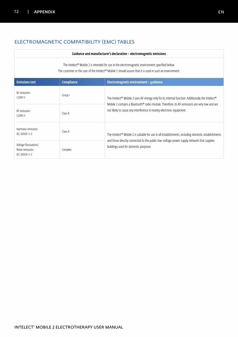
Guidance and manufacturer’s declaration – electromagnetic emissions
The Intelect® Mobile 2 is intended for use in the electromagnetic environment specified below.
The customer or the user of the Intelect® Mobile 2 should assure that it is used in such an environment.
Emissions test Compliance Electromagnetic environment – guidance
RF emissions CISPR 11
Group 1The Intelect® Mobile 2 uses RF energy only for its internal function. Additionally the Intelect®
Mobile 2 contains a Bluetooth® radio module. Therefore, its RF emissions are very low and are
not likely to cause any interference in nearby electronic equipment.RF emissions CISPR 11
Class B
Harmonic emissions IEC 61000-3-2
Class AThe Intelect® Mobile 2 is suitable for use in all establishments, including domestic establishments
and those directly connected to the public low-voltage power supply network that supplies
buildings used for domestic purposes.Voltage fluctuations/ flicker emissions IEC 61000-3-3
Complies
73 APPENDIX EN
INTELECT® MOBILE 2 ELECTROTHERAPY USER MANUAL
ELECTROMAGNETIC COMPATIBILITY (EMC) TABLES (CONTINUED)
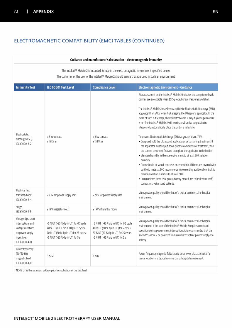
Guidance and manufacturer’s declaration – electromagnetic immunity
The Intelect® Mobile 2 is intended for use in the electromagnetic environment specified below.
The customer or the user of the Intelect® Mobile 2 should assure that it is used in such an environment.
Immunity Test IEC 60601 Test Level Compliance Level Electromagnetic Environment - Guidance
Electrostatic discharge (ESD) IEC 61000-4-2
± 8 kV contact ± 15 kV air
± 8 kV contact ± 15 kV air
Risk assessment on the Intelect® Mobile 2 indicates the compliance levels claimed are acceptable when ESD-precautionary measures are taken. The Intelect® Mobile 2 may be susceptible to Electrostatic Discharge (ESD) at greater than ±7 kV when first grasping the Ultrasound applicator. In the event of such a discharge, the Intelect® Mobile 2 may display a permanent error. The Intelect® Mobile 2 will terminate all active outputs (stim, ultrasound), automatically place the unit in a safe state. To prevent Electrostatic Discharge (ESD) at greater than ±7 kV:• Grasp and hold the Ultrasound applicator prior to starting treatment. If
the applicator must be put down prior to completion of treatment, stop the current treatment first and then place the applicator in the holder.
• Maintain humidity in the use environment to at least 50% relative humidity.
• Floors should be wood, concrete, or ceramic tile. If floors are covered with synthetic material, DJO recommends implementing additional controls to maintain relative humidity to at least 50%.
• Communicate these ESD-precautionary procedures to healthcare staff, contractors, visitors and patients.
Electrical fast transient/burst IEC 61000-4-4
± 2 kV for power supply lines ± 2 kV for power supply linesMains power quality should be that of a typical commercial or hospital environment.
Surge IEC 61000-4-5
± 1 kV line(s) to line(s) ± 1 kV differential modeMains power quality should be that of a typical commercial or hospital environment.
Voltage dips, short interruptions and voltage variations on power supply input lines IEC 61000-4-11
<5 % UT (>95 % dip in UT) for 0,5 cycle 40 % UT (60 % dip in UT) for 5 cycles 70 % UT (30 % dip in UT) for 25 cycles <5 % UT (>95 % dip in UT) for 5 s
<5 % UT (>95 % dip in UT) for 0,5 cycle 40 % UT (60 % dip in UT) for 5 cycles 70 % UT (30 % dip in UT) for 25 cycles <5 % UT (>95 % dip in UT) for 5 s
Mains power quality should be that of a typical commercial or hospital environment. If the user of the Intelect® Mobile 2 requires continued operation during power mains interruptions, it is recommended that the Intelect® Mobile 2 be powered from an uninterruptible power supply or a battery.
Power frequency (50/60 Hz) magnetic field IEC 61000-4-8
3 A/M 3 A/M Power frequency magnetic fields should be at levels characteristic of a typical location in a typical commercial or hospital environment.
NOTE UT is the a.c. mains voltage prior to application of the test level.
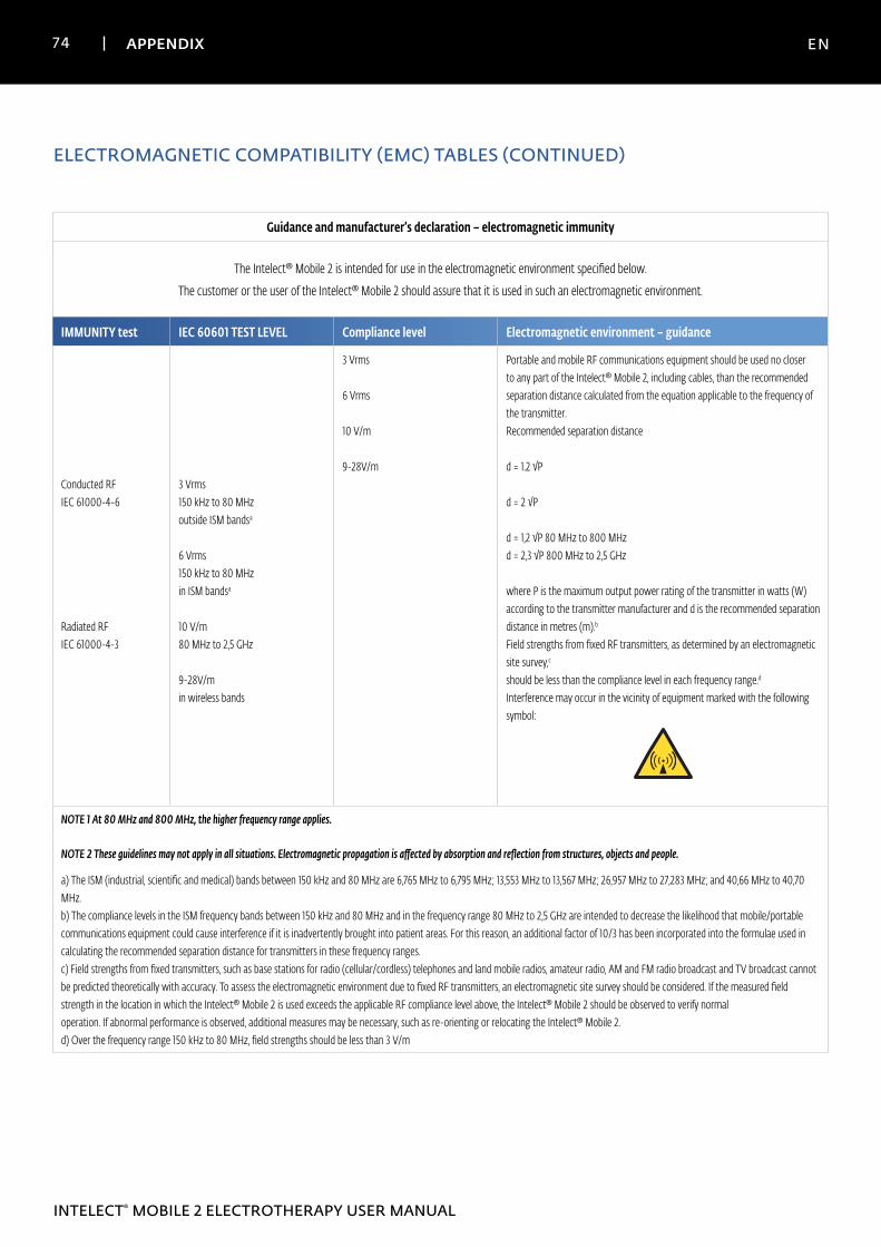
74 APPENDIX EN
INTELECT® MOBILE 2 ELECTROTHERAPY USER MANUAL
ELECTROMAGNETIC COMPATIBILITY (EMC) TABLES (CONTINUED)
Guidance and manufacturer’s declaration – electromagnetic immunity
The Intelect® Mobile 2 is intended for use in the electromagnetic environment specified below.
The customer or the user of the Intelect® Mobile 2 should assure that it is used in such an electromagnetic environment.
IMMUNITY test IEC 60601 TEST LEVEL Compliance level Electromagnetic environment – guidance
Conducted RF IEC 61000-4-6
Radiated RF IEC 61000-4-3
3 Vrms 150 kHz to 80 MHz outside ISM bandsa 6 Vrms 150 kHz to 80 MHz in ISM bandsa 10 V/m 80 MHz to 2,5 GHz 9-28V/m in wireless bands
3 Vrms 6 Vrms 10 V/m 9-28V/m
Portable and mobile RF communications equipment should be used no closer to any part of the Intelect® Mobile 2, including cables, than the recommended separation distance calculated from the equation applicable to the frequency of the transmitter. Recommended separation distance d = 1.2 √P d = 2 √P d = 1,2 √P 80 MHz to 800 MHz d = 2,3 √P 800 MHz to 2,5 GHz where P is the maximum output power rating of the transmitter in watts (W) according to the transmitter manufacturer and d is the recommended separation distance in metres (m).b Field strengths from fixed RF transmitters, as determined by an electromagnetic site survey,c should be less than the compliance level in each frequency range.d Interference may occur in the vicinity of equipment marked with the following symbol:
NOTE 1 At 80 MHz and 800 MHz, the higher frequency range applies.
NOTE 2 These guidelines may not apply in all situations. Electromagnetic propagation is affected by absorption and reflection from structures, objects and people.
a) The ISM (industrial, scientific and medical) bands between 150 kHz and 80 MHz are 6,765 MHz to 6,795 MHz; 13,553 MHz to 13,567 MHz; 26,957 MHz to 27,283 MHz; and 40,66 MHz to 40,70 MHz. b) The compliance levels in the ISM frequency bands between 150 kHz and 80 MHz and in the frequency range 80 MHz to 2,5 GHz are intended to decrease the likelihood that mobile/portable communications equipment could cause interference if it is inadvertently brought into patient areas. For this reason, an additional factor of 10/3 has been incorporated into the formulae used in calculating the recommended separation distance for transmitters in these frequency ranges. c) Field strengths from fixed transmitters, such as base stations for radio (cellular/cordless) telephones and land mobile radios, amateur radio, AM and FM radio broadcast and TV broadcast cannot be predicted theoretically with accuracy. To assess the electromagnetic environment due to fixed RF transmitters, an electromagnetic site survey should be considered. If the measured field strength in the location in which the Intelect® Mobile 2 is used exceeds the applicable RF compliance level above, the Intelect® Mobile 2 should be observed to verify normal operation. If abnormal performance is observed, additional measures may be necessary, such as re-orienting or relocating the Intelect® Mobile 2. d) Over the frequency range 150 kHz to 80 MHz, field strengths should be less than 3 V/m
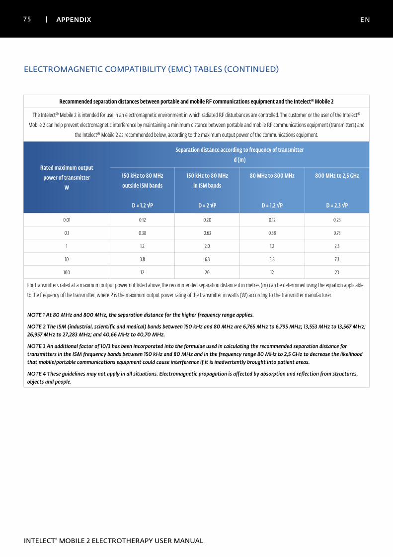
75 APPENDIX EN
INTELECT® MOBILE 2 ELECTROTHERAPY USER MANUAL
ELECTROMAGNETIC COMPATIBILITY (EMC) TABLES (CONTINUED)
Recommended separation distances between portable and mobile RF communications equipment and the Intelect® Mobile 2
The Intelect® Mobile 2 is intended for use in an electromagnetic environment in which radiated RF disturbances are controlled. The customer or the user of the Intelect®
Mobile 2 can help prevent electromagnetic interference by maintaining a minimum distance between portable and mobile RF communications equipment (transmitters) and
the Intelect® Mobile 2 as recommended below, according to the maximum output power of the communications equipment.
Rated maximum outputpower of transmitter
W
Separation distance according to frequency of transmitterd (m)
150 kHz to 80 MHzoutside ISM bands
D = 1.2 √P
150 kHz to 80 MHzin ISM bands
D = 2 √P
80 MHz to 800 MHz
D = 1.2 √P
800 MHz to 2,5 GHz
D = 2.3 √P
0.01 0.12 0.20 0.12 0.23
0.1 0.38 0.63 0.38 0.73
1 1.2 2.0 1.2 2.3
10 3.8 6.3 3.8 7.3
100 12 20 12 23
For transmitters rated at a maximum output power not listed above, the recommended separation distance d in metres (m) can be determined using the equation applicable
to the frequency of the transmitter, where P is the maximum output power rating of the transmitter in watts (W) according to the transmitter manufacturer.
NOTE 1 At 80 MHz and 800 MHz, the separation distance for the higher frequency range applies.
NOTE 2 The ISM (industrial, scientific and medical) bands between 150 kHz and 80 MHz are 6,765 MHz to 6,795 MHz; 13,553 MHz to 13,567 MHz; 26,957 MHz to 27,283 MHz; and 40,66 MHz to 40,70 MHz.
NOTE 3 An additional factor of 10/3 has been incorporated into the formulae used in calculating the recommended separation distance for transmitters in the ISM frequency bands between 150 kHz and 80 MHz and in the frequency range 80 MHz to 2,5 GHz to decrease the likelihood that mobile/portable communications equipment could cause interference if it is inadvertently brought into patient areas.
NOTE 4 These guidelines may not apply in all situations. Electromagnetic propagation is affected by absorption and reflection from structures, objects and people.

© 0
9/20
19 D
JO -
13-1
603-
EN -
Rev
A
DJO, LLC | 1430 Decision Street | Vista | CA 92081-8553 | U.S.A.
www.DJOglobal.com
DJO France SAS
Centre Européen de Frêt 3 rue de Bethar
64990 Mouguerre • France
T: + 33 (0) 5 59 52 86 90 • F: + 33 (0) 5 59 52 86 91
DJOglobal.com