Embed Size (px)
Citation preview
Intelligent Camera Control for
Graphical Environments
bySteven Mark Drucker
S.M. Massachusetts Institute of Technology (1989)ScB. Brown University (1984)
Submitted to the Program in Media Arts and Sciences, School of Architecture and Planning,
in partial fulfullment of the requirements for the degree of Doctor of Philosophy
at the Massachusetts Institute of Technology
June 1994
Massachusetts Institute of Technology, 1994. All rights reserved.
Author
_________________________________________________________________Steven M. Drucker
Program in Media Arts and SciencesApril 29, 1994
Certified by
_____________________________________________________________David Zeltzer
Principle Research ScientistResearch Laboratory for Electronics
Accepted by
____________________________________________________________Stephen A. Benton
ChairpersonDepartmental Committee on Graduate Students
Program in Media Arts and Sciences
This document was created with FrameMaker 4.0.4
Intelligent Camera Control for
Graphical Environments
by
Steven Mark Drucker
Submitted to the Program in Media Arts and Sciences,
School of Architecture and Planning,
on April 29, 1994
in partial fulfullment of the requirements for the degree of
Doctor of Philosophy
at the
Massachusetts Institute of Technology
Abstract
:
Too often in the field of computer graphics, practitioners have been more concerned with
the question of
how
to move a camera rather than
why
to move it. This thesis addresses the
core question of
why
the camera is being placed and moved and uses answers to that ques-
tion to provide a more convenient, more intelligent method for controlling virtual cameras
in computer graphics. After discussing the general sorts of activities to be performed in
graphical environments, this thesis then contains a derivation of some camera primitives
that are required, and examines how they can be incorporated into different interfaces. A
single, consistent, underlying framework for camera control across many different
domains has been posited and formulated in terms of constrained optimization. Examples
from different application domains demonstrate a variety of interface styles that have all
been implemented on top of the underlying framework. Evaluations for each application
are also given.
Thesis Supervisor: Dr. David Zeltzer, Principle Research Scientist at the Research Laboratory in Electronics.
This work was supported in part by ARPA/Rome Laboratories, NHK (Japan Broadcasting Co.), the Office of Naval
Research, and equipment gifts from Apple Computer, Hewlett-Packard, and Silicon Graphics.
This document was created with FrameMaker 4.0.4
Thesis Committee
Chairperson______________________________________________________________David Zeltzer, Ph.D.
Principle Research ScientistResearch Laboratory for Electronics
Member_________________________________________________________________Glorianna Davenport
Associate Professor of Media TechnologyProgram in Media Arts and Sciences
Member_________________________________________________________________Pattie Maes, Ph.D
Assistant Professor of Media TechnologyProgram in Media Arts and Sciences
Member_________________________________________________________________Alex Pentland, Ph.D
Associate Professor of Computers, Communication, and Design TechnologyProgram in Media Arts and Sciences
April, 1994
This document was created with FrameMaker 4.0.4
Acknowledgements 4
Intelligent Camera Control Steven M. Drucker
Acknowledgements
This work would not have been possible without the support and encouragement of a great
many people. I wish to thank all those who have influenced me both during and before my
graduate career. Some in particular deserve special mention.
First, my parents have been a source of strength for me in every shape and form. They
have always had a belief in my ability to succeed, even when I have had my own doubts.
Without their kindness, devotion, and unwaivering support, I never would have even been
able to start this long voyage to a PhD, much less have completed it.
My brother David and I have always shared a special bond as far back as I can remember.
Watching Star Trek and The Outer Limits together started my interest in those areas which
led me to MIT in the first place. My sister-in-law Pam has helped me through these long
years as a graduate student always with sound advice. A special thanks to my Godmother
Aunt Lee who is always wondering what kind of PhD degree am I getting anyway. My
longtime friend Danny Shevitz has grown with me. Years ago we built the game of Life
together one snow day, and we still manage to share our lives with each other even from
opposite sides of the country.
During my time at MIT, I have learned most from my fellow students both at the Media
Lab and at the AI Lab. Sundar Narasimhan has an amazing breadth of knowledge and he
has helped me on every topic imaginable. Without Eric Aboaf, my master’s thesis would
have never been possible. David Sturman took me under his wing and introduced me to
the graphics community. Steve Pieper and David Chen showed me what it means to create
a computer graphical system. With Mike McKenna, the whole ‘playpen’ crew has taught
me more about how things are really done than any class could ever teach. Paul Dworkin
has always been ready and willing to offer helpful advice and assistance, and Michael
Johnson has always been there with good suggestions. Margaret Minsky has been a con-
stant source of ideas and enthusiasm as has Steve Strassman. Peter Schröder shared with
Acknowledgements 5
Intelligent Camera Control Steven M. Drucker
me the joys of rendering and of a fine bottle of wine. I especially want to thank my friend
and co-director Tinsley Galyean, for his energy, enthusiasm, and drive. Without him, my
time at MIT would have been a much less fruitful experience. I also wish to recognize just
some of my friends and fellow students who have helped me throughout my studies: Karl
Sims, John Durand, Mark Itzler, Bern Haan, David Laidlaw and Barb Meier, Azita Ghahr-
amani, Stephanie Houde, Tim & Karen Catlin, Pattie Cohen, Irfan Essa, Mark Lucente,
Brian Eberman, Stan Sclaroff, John Underkoffler, Wendy Plesniak, Scott Higgins, Janet
Cahn, Joe Chung, Joe Rosen, Dave Small, and Bruce Blumberg. And in particular, fellow
stooges Mike Drumheller and Matt Fitzgibbon have shared many an entertaining evening
and have always been there when I needed them, both for advice, and ideas.
The administrative staff have helped minimize the unending paperwork that is the life of a
graduate student. Linda Peterson has always been the person to go to whenever there is a
problem and she’s always been able to fix it. Thanks for being there. I also want to thank
Lena Davis for bailing me out on many an emergency Federal Express Package and travel
report. I am obliged to thank my sponsors at the Media Lab, DARPA and NHK for provid-
ing me with an opportunity to do my graduate research.
My teachers and advisors have also been great sources of guidance. I wish to thank my
advisor and committee members for their effort and time in their hectic schedules. I don’t
think I have seen anyone work harder than an MIT Professor! David Zeltzer has always
protected me from the monetary worries of funding and I thank him for guiding me
through the difficult process of a Ph.D. thesis. Glorianna Davenport has helped me achieve
the combination of technique and aesthetics that I wanted to have in my thesis. Pattie Maes
has been a source of several inspirations throughout this thesis work. And Sandy Pentland
has always helped make sure that my technical details were grounded in reality. I also
want to thank my previous advisors and professors who helped lead me to where I am
now. Tomas Lozano-Pérez introduced me to the field of robotics and has always been
available to offer advice when I’ve needed it. Andy van Dam has been more than advisor. I
consider myself lucky to count him as a friend. John Hughes has also been a source of a
wealth of knowledge in the field of computer graphics. John Hollerbach, Chris Atkeson,
and Marc Raibert helped show me what it means to be an engineer, and Whitman Richards
Acknowledgements 6
Intelligent Camera Control Steven M. Drucker
showed me how to turn an Incomplete into a book chapter.
I wish to thank my domain experts Michael Sand, Eric Eisendratt, Glorianna Davenport,
and Tom Sheridan, who have provided inciteful commentary on the examples that I have
demonstrated.
Finally I want to thank Lourdes for her love and devotion through this all. She has put up
with my long hours and has always been there to help me. I just want to say to her, “Eu te
Amo”.
Table Of Contents 7
Intelligent Camera Control Steven M. Drucker
Table Of Contents
Acknowledgements ...........................................................................................................4
Table Of Contents .............................................................................................................7
List of Figures .................................................................................................................11
List of Tables ...................................................................................................................13
Chapter 1. Introduction .................................................................................................14
1.1 Reader’s Guide ....................................................................................16
Chapter 2. Intelligent Camera Control ........................................................................18
2.1 General Problem ..................................................................................18
Virtual Environments ..........................................................................24
User interface design ...........................................................................24
Software agents ...................................................................................25
2.2 Overview of the solution proposed .....................................................27
Framework ..........................................................................................27
Generality ............................................................................................27
Efficiency ............................................................................................28
Robustness ...........................................................................................28
Chapter 3. Background and related work ...................................................................29
3.1 Computer Graphics .............................................................................29
Interpolation ........................................................................................29
Physical Simulation .............................................................................30
Optimization ........................................................................................30
Virtual Environments & Scientific Visualization ...............................32
Automatic Camera Control .................................................................34
3.2 Robotics ...............................................................................................36
Pathplanning ........................................................................................36
Sensor Positioning ...............................................................................37
3.3 Teleoperation .......................................................................................38
3.4 Human factors & Human Computer Interaction .................................39
3.5 Human Perceptual Capabilities ...........................................................39
3.6 Cinematography ..................................................................................41
Table Of Contents 8
Intelligent Camera Control Steven M. Drucker
Chapter 4. Taxonomy of Interactive Domains .............................................................42
4.1 The Problem Domain ..........................................................................42
4.2 Terminology ........................................................................................43
4.3 Taxonomy ............................................................................................43
Exploration ..........................................................................................44
Planning ...............................................................................................47
Rehearsal .............................................................................................49
Control .................................................................................................50
Development cycle ..............................................................................51
4.4 Interaction ............................................................................................53
Summary .............................................................................................54
4.5 Tasks demonstrated in this thesis ........................................................56
Virtual Museum ...................................................................................56
Mission Planner ...................................................................................56
Conversation ........................................................................................56
Virtual Football Game .........................................................................56
Visibility assistant ...............................................................................57
Chapter 5. Camera Primitives ......................................................................................58
5.1 Procedural Representation ...................................................................58
Reusability of camera behaviors .........................................................59
Problems with the procedural representation ......................................59
5.2 Deriving Primitives as Constraints ......................................................60
5.3 Cinematic Constraints .........................................................................62
5.4 Task completion constraints ................................................................71
Object Visibility ..................................................................................71
Object manipulability ..........................................................................71
5.5 Object appearance ...............................................................................71
5.6 Physical Limitations ............................................................................72
5.7 Human Factors ....................................................................................72
5.8 The Viewing Transformation ..............................................................73
Derivation of the standard Viewing Transformation ..........................73
Blinn’s Formulation: Where am I? What am I Looking At? [Blinn88] 78
5.9 Object and Camera State Functions ....................................................79
5.10 Constrained Optimization Techniques ...............................................81
Sequential Quadratic Programming ....................................................82
Table Of Contents 9
Intelligent Camera Control Steven M. Drucker
Local Minima ......................................................................................86
5.11 Camera Constraints Formalized .........................................................87
Direct constraints on DOFs in relation to the environment: ...............87
Direct constraints on DOFs in relation to a single object: ..................88
Projective constraints based on projection of an object: .....................89
Constraints based on entire environment: ...........................................92
Constraints on derivatives of DOFs: ...................................................95
Changing constraints: ..........................................................................96
Constraints based on another camera: .................................................97
5.12 Blinn’s formulations revisited ............................................................98
Chapter 6. From Task to Interface .............................................................................100
6.1 Example: The Virtual Museum .........................................................100
Implementation ..................................................................................103
Results ...............................................................................................108
6.2 Example: The Mission Planner .........................................................110
Implementation ..................................................................................112
Results ...............................................................................................113
6.3 Example: Filming a conversation ......................................................114
Implementation ..................................................................................115
Extensions to agents: .........................................................................122
Results ...............................................................................................123
6.4 Example: the Virtual Football Game ................................................123
Implementation ..................................................................................125
Results ...............................................................................................129
6.5 Example: Visibility Assistant ............................................................130
Implementation ..................................................................................130
Results ...............................................................................................133
Chapter 7. Evaluations of Camera Control Interfaces .............................................134
7.1 Framework sufficiently representative: .............................................134
7.2 Types of assistance: ...........................................................................135
Types of assistance in the Virtual Museum ......................................135
Types of assistance in the Mission Planner System ..........................138
Types of assistance for Conversation Agent .....................................139
Types of assistance for Virtual Football Game .................................140
Types of assistance for Visibility Assistant ......................................142
Table Of Contents 10
Intelligent Camera Control Steven M. Drucker
7.3 Convenience of the framework .........................................................143
7.4 How well do the camera primitives work? ........................................143
Local Minima ....................................................................................143
Efficiency ..........................................................................................145
Stylistic Expressiveness ....................................................................145
Chapter 8. Conclusions and Future Work .................................................................148
8.1 Conclusions .......................................................................................148
8.2 Future Work ......................................................................................149
8.3 Improving current work ....................................................................149
8.4 Extending the current work ...............................................................150
Appendix 1:Path Planning .......................................................................................... 151
A1.1 A* ...................................................................................................153
A1.2 Room to Room Planning ............................................................154
A1.3 Travel within a Room .................................................................157
A1.4 Tour Planning ..............................................................................159
Appendix 2:Visibility Determination ......................................................................... 161
Appendix 3:Graphical Environment Systems ........................................................... 164
A3.1 TK ..................................................................................................164
A3.2 Communication libraries ...........................................................165
A3.3 Head mounted display/dataglove ...........................................165
A3.4 Radiosity/Raytracing/Visibility ...............................................166
A3.5 Video Objects ...............................................................................167
A3.6 Object Oriented Tcl [incr tcl] .....................................................169
A3.7 General Optimization .................................................................169
A3.8 Spline fitting and evaluation .....................................................169
A3.9 Quaternions ..................................................................................171
Appendix 4:Feasible Sequential Quadratic Programming ...................................... 172
A4.1 The CFSQP algorithm .................................................................173
A4.2 Detailed description to 3d fsqp interface. ................................174
A4.3 Hardcoded FSQP Camera Primitives .......................................177
A4.4 TCL-Code to implement over the shoulder constraint ..........178
A4.5 C-Code to implement over the shoulder constraint ...............185
References .....................................................................................................................194
List of Figures 11
Intelligent Camera Control Steven M. Drucker
List of Figures
The camera agent ..............................................................................................................15
The Virtual Camera with its 7 degrees of freedom. ..........................................................20
Surgical Simulation Process Cycle ...................................................................................53
Pseudocode for vertigo shot ..............................................................................................59
Extreme close up ............................................................................................................... 63
Big close up....................................................................................................................... 64
Close up............................................................................................................................. 64
Medium close up ............................................................................................................... 65
Med. close3/4 .................................................................................................................... 65
Medium shot...................................................................................................................... 66
Mediumlong shot............................................................................................................... 66
Long shot........................................................................................................................... 67
Very long shot ................................................................................................................... 67
Extreme long ..................................................................................................................... 68
Two shot............................................................................................................................ 68
Over shoulder .................................................................................................................... 69
Over shoulder2 .................................................................................................................. 69
World Space ......................................................................................................................74
Eye Space ..........................................................................................................................75
Normalized Coordinates after perspective transformation................................................75
Path planning with intersection inequality constraints......................................................94
Sum of “repulsive” and “attractive” constraints for path planning optimization..............94
Visibility regions are the complement of shadows cast from a light. ...............................95
The Virtual Museum System...........................................................................................104
Generic Camera Module .................................................................................................105
Wiring diagram between interface widgets and modules. ..............................................106
Schematic view of the “path” camera module ................................................................108
Overhead view of museum..............................................................................................109
List of Figures 12
Intelligent Camera Control Steven M. Drucker
4 shots of the museum along a computed path................................................................109
Overview of the mission planner ....................................................................................112
Overhead view of mission planning system....................................................................113
Over-the-shoulder shot in mission planning system .......................................................113
Visibility evasion from threat in mission planning system.............................................114
Filming a conversation [Katz88].....................................................................................116
Overview of camera agent...............................................................................................118
Agent generated over-the-shoulder shot. ........................................................................123
Overview of virtual football game ..................................................................................126
Visual Programming Environment for camera modules.................................................127
Overhead view of the football game ...............................................................................128
Playback Controller.........................................................................................................129
View from “game camera” of virtual football game.......................................................129
Visibility Assistant Overview .........................................................................................130
Visibility Assistant ..........................................................................................................133
Room connectivity graph for the museum with a path found by A* ..............................154
Navigation function calculated with a Manhattan metric ...............................................155
3 distance metrics and resulting paths.............................................................................156
An eventual path through 4 rooms of the museum. ........................................................157
Calculating a path potential function. .............................................................................159
Visibility problem: oblique view and camera view. .......................................................161
Visibility map construction .............................................................................................162
Visibility potential map...................................................................................................162
Visible position for camera. ............................................................................................163
Video Objects..................................................................................................................168
Simple bounds control window for fsqp. ........................................................................178
List of Tables 13
Intelligent Camera Control Steven M. Drucker
List of Tables
Common Cinematic Terms ............................................................................................... 21
Interactive Domains .......................................................................................................... 44
Frequency of Interaction ................................................................................................... 54
Style of Interaction ............................................................................................................ 54
Standard Functions of an Object ....................................................................................... 80
Standard Functions of Camera State ................................................................................. 81
Examples of Direct Constraints relating to the environment: ........................................... 88
Examples of Direct Constraints Relating to an Object: .................................................... 89
Examples of Projection Constraints: ................................................................................. 91
Examples of constraints on derivatives of DOFs .............................................................. 96
Examples of changing constraints:.................................................................................... 97
Examples of constraints based on other cameras: ............................................................. 98
Visual Tasks in an exploratory domain........................................................................... 102
Tasks in the Mission Planner .......................................................................................... 110
Tasks in Filming a Conversation..................................................................................... 115
Tasks from Virtual Football Game.................................................................................. 125
Introduction 14
Intelligent Camera Control Steven M. Drucker
CHAPTER 1. INTRODUCTION
Too often in the field of computer graphics, practitioners have been more concerned with
the question of how to move a camera rather than why to move it. There is a great deal of
research devoted to proper representations for interpolating camera motion conveniently
or in what sequence transformations should be performed in order to provide efficient cull-
ing of objects outside of the field of view of the camera. However, very few researchers
have looked at the basic reasons for which cameras are used in computer graphics. This
thesis addresses the core question of why the camera is being placed and moved and uses
answers to that question to provide a more convenient, more intelligent method for con-
trolling virtual cameras in computer graphics.
Once we know why to change the camera’s view of the world, we can then start addressing
how to change it. In this thesis, I examine similarities across many different activities that
can be described in terms of camera primitives. These primitives can be conveniently and
powerfully described as constraints that must be satisfied to achieve the designated tasks.
A single, consistent, underlying framework for camera control across many different
domains has been posited and formulated in terms of constrained optimization. After dis-
cussing the general sorts of activities to be performed in graphical environments, this the-
sis then contains a derivation of some of the primitives that are required, and examines
how they can be incorporated into different interfaces.
The primitives can be viewed as behaviors for software agents of varying levels of sophis-
tication. The agents might simply provide specific interfaces to a variety of camera primi-
tives, or the agents might combine primitives, sequence them, connect the primitives to
devices, or use the primitives as behaviors for autonomous action.
Introduction 15
Intelligent Camera Control Steven M. Drucker
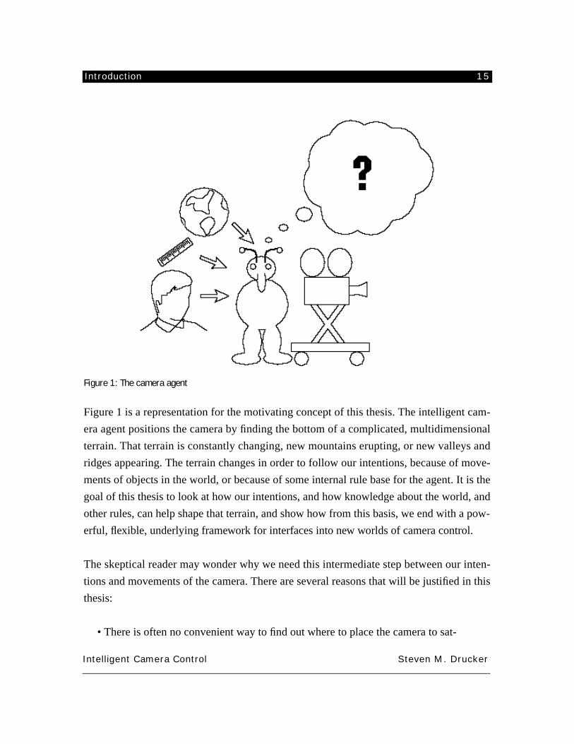
Figure 1: The camera agent
Figure 1 is a representation for the motivating concept of this thesis. The intelligent cam-
era agent positions the camera by finding the bottom of a complicated, multidimensional
terrain. That terrain is constantly changing, new mountains erupting, or new valleys and
ridges appearing. The terrain changes in order to follow our intentions, because of move-
ments of objects in the world, or because of some internal rule base for the agent. It is the
goal of this thesis to look at how our intentions, and how knowledge about the world, and
other rules, can help shape that terrain, and show how from this basis, we end with a pow-
erful, flexible, underlying framework for interfaces into new worlds of camera control.
The skeptical reader may wonder why we need this intermediate step between our inten-
tions and movements of the camera. There are several reasons that will be justified in this
thesis:
• There is often no convenient way to find out where to place the camera to sat-
Introduction 16
Intelligent Camera Control Steven M. Drucker
isfy our intentions, but there is often a convenient mapping between our inten-
tions and a “constraint” terrain.
• That mapping can be described in formal, mathematical terms that can be used
to generalize knowledge across many different domains, rather than only in
the domain for which an intention was originally derived.
• The terrain represents a convenient way of combining several intentions at the
same time.
• The terrain responds to an ever changing world, making the camera, which
follows that terrain, respond automatically to changes in the environment.
• The agent’s own internal knowledge can change the terrain, providing a means
of combining the autonomous action of the agent with the changing environ-
ment, and our own changing intentions.
The new and original knowledge that is contributed by this thesis is a more thorough
understanding of how and why humans control their view within computer graphic envi-
ronments. A single, unifying structure for controlling the camera is proposed and a variety
of camera primitives (or behaviors) are examined in several different application domains.
The utility of the underlying framework is shown by the wide-reaching application
domains for which the framework is applicable.
1.1 Reader’s Guide
In Chapter 2, I describe the graphical environment and the virtual camera and then set
forth the basic problem and the solution scheme proposed.
In Chapter 3, I discuss related areas of research in computer graphics, constrained optimi-
zation, robotics, user interface design, and film theory.
In Chapter 4, I set forth a taxonomy to describe the different kinds of graphical environ-
ments and the visual requirements necessary to achieve goals in each domain.
In Chapter 5, camera primitives and constraints are derived and discussed formally.
Introduction 17
Intelligent Camera Control Steven M. Drucker
In Chapter 6, I look at the different ways that interfaces can be built using the proposed
framework in five different applications; a mission planning system, a virtual museum,
filming a conversation, a virtual football game, and a visibility assistant.
Chapter 7 contains an evaluation of the applications described in the previous chapter.
Chapter 8 presents conclusions and future work.
Appendix 1 presents the details of the path planning algorithm that was developed for the
virtual museum.
Appendix 2 presents the details of the visibility algorithm that was developed for the cam-
era framework.
Appendix 3 discusses the graphical prototyping environment in which all the examples
have been implemented.
Appendix 4 discusses the optimization software that was used for solving the constrained
optimization problem at the core of the camera primitives. It also gives code examples of
how to combine a number of camera primitives.
Intelligent Camera Control 18
Intelligent Camera Control Steven M. Drucker
CHAPTER 2. INTELLIGENT CAMERA CONTROL
2.1 General Problem
Current interest in so-called immersive interfaces and large-scale virtual worlds serves to
highlight the difficulties of orientation and navigation in synthetic environments, including
abstract “data-spaces” and “hypermedia” as well as more familiar modeled exterior and
interior spaces. As Ware and Osborne [Ware90] point out, this is equivalent to manipulat-
ing a viewpoint – a synthetic camera – in and through the environment, and a number of
recent articles have discussed the camera control problem in detail.
Nearly all of this work, however, has focused on techniques for directly manipulating the
camera. In my view, this is the source of much of the difficulty. Direct control of several
degrees of freedom of the camera is often problematic and forces the human participant to
attend to the interfaces and its “control knobs” in addition to – or instead of – the goals and
constraints of the task at hand. If the intention of the user of the system is, for example, to
observe some object X, then allowing him or her to simply tell the system, “Show me
object X” is a more direct and productive interface. This thesis will explore ways in which
we can generalize instances of this form of “task level interaction” for synthetic cameras
across a wide variety of tasks.
Before the statement of the general problem, it is first necessary to define two essential
terms: Computer Mediated Graphical Environment (or just graphical environment), and
the synthetic or virtual camera. By graphical environment, I mean any interactive, graphi-
cally rendered computer display which is intimately associated with a geometric model.
Graphical environments are usually a spatial representation of an information space or a
Intelligent Camera Control 19
Intelligent Camera Control Steven M. Drucker
representation of an actual environment. Types of graphical environments, and the visual
tasks that are associated with them will be discussed in chapter 4.
By virtual camera, I mean the method of specifying the parameters which control the view
within the graphical environment. Virtual cameras are, by definition, a crucial part of any
graphical environment because the camera’s view is a primary means by which informa-
tion about the graphical environment is transferred to the user. Other interface modalities,
such as aural and haptic exist, but by and large, most of the information currently comes
through the visual system and this thesis is devoted to examining only the visual modality.
Without being able to control the virtual camera, the user is left with a single view of only
a small portion of a potentially infinite environment. It is important that the user be able to
affect what s/he is seeing either by changing parameters that control what is occurring in
the graphical envrironment directly, or by changing the view through manipulating param-
eters of the virtual camera within the graphical environment.
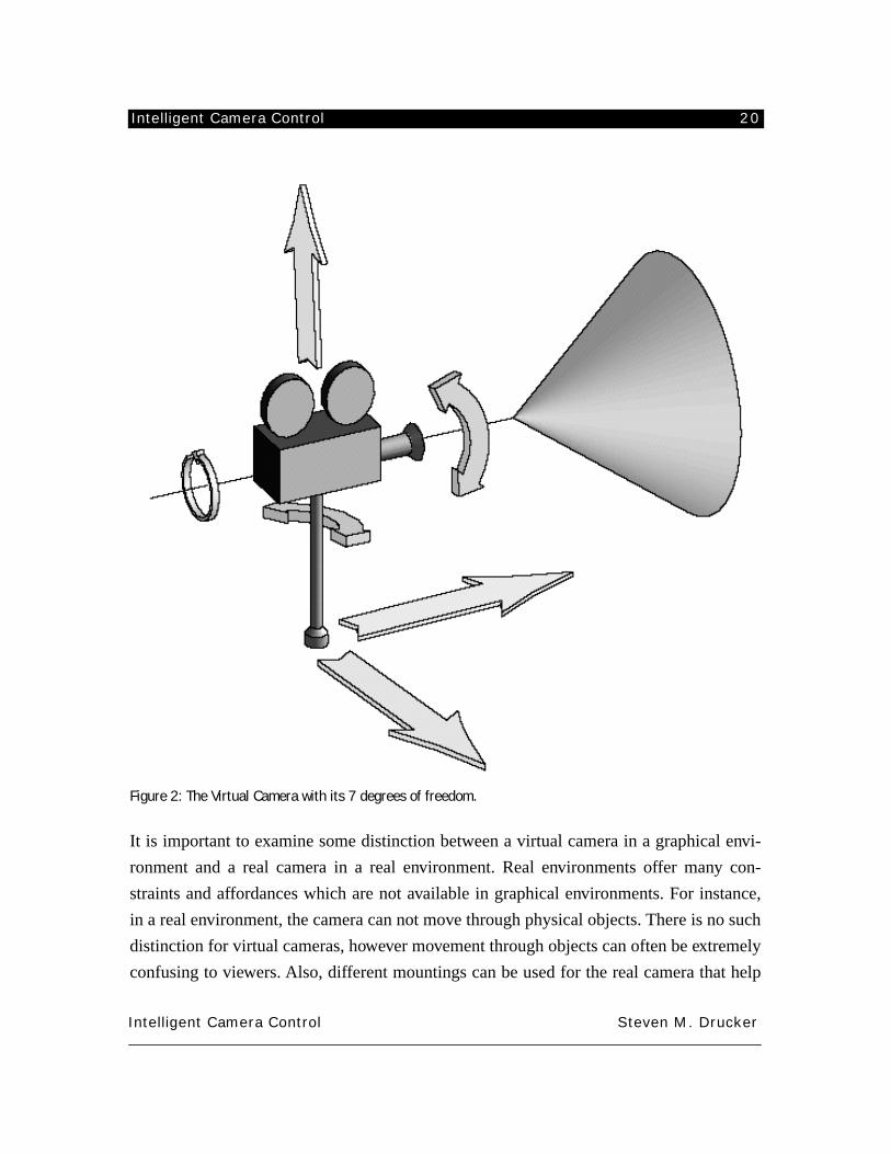
In general, I will consider seven degrees of freedom that must be controlled: three for the
cartesian position of the virtual camera in space, three for the orientation of the camera,
and a final one for controlling the field of view for the camera (see figure 2). There are sev-
eral other parameters of a camera that can be controlled but will not be considered in this
thesis. Some of those are: the aspect ratio of the resultant frame, the depth of field for the
camera, the “shutter speed”, and lighting of the environment. These additional parameters
are not considered because most computer graphic systems model an idealized “pin-hole”
camera where there can be infinite depth of field (everything is in view at once), infinitesi-
mal shutter speed (no motion blur), and direct control over the lighting within a GE. Con-
trolling these other parameters can often greatly enhance the look of the resulting image,
but these tend to be extremely subjective and stylistic changes [Potmesil81]. For the pur-
poses of this thesis, the idealized model for the virtual camera is used.
Intelligent Camera Control 20
Intelligent Camera Control Steven M. Drucker
Figure 2: The Virtual Camera with its 7 degrees of freedom.
It is important to examine some distinction between a virtual camera in a graphical envi-
ronment and a real camera in a real environment. Real environments offer many con-
straints and affordances which are not available in graphical environments. For instance,
in a real environment, the camera can not move through physical objects. There is no such
distinction for virtual cameras, however movement through objects can often be extremely
confusing to viewers. Also, different mountings can be used for the real camera that help
Intelligent Camera Control 21
Intelligent Camera Control Steven M. Drucker
control the way the camera can move. For instance, a fluid head may be used, which pro-
duces viscous damping which resists sudden changes of position for the camera head
(rotation and tilt). Also, it is inconvenient to rotate the camera about its direction of gaze
(roll) which is rarely done in filming real scenes. There are, however, some inherent
advantages that virtual cameras have over real cameras. Because there are no built in con-
straints on the virtual camera’s degrees of freedom, the virtual camera can move to any
place within the graphical environment, even if that would be physically unfeasible for a
real camera. This might mean flying along with a ball as it is thrown in midair, or moving
through a window without any means of support. Also, when controlling virtual cameras,
one does not need to worry about velocity limitations or torque constraints of motors that
might be needed to control real cameras. In addition, in graphical environments, the
assumption is made that the position of objects in the environment can be easly recovered,
something which is still in general an unsolved problem for real environments.
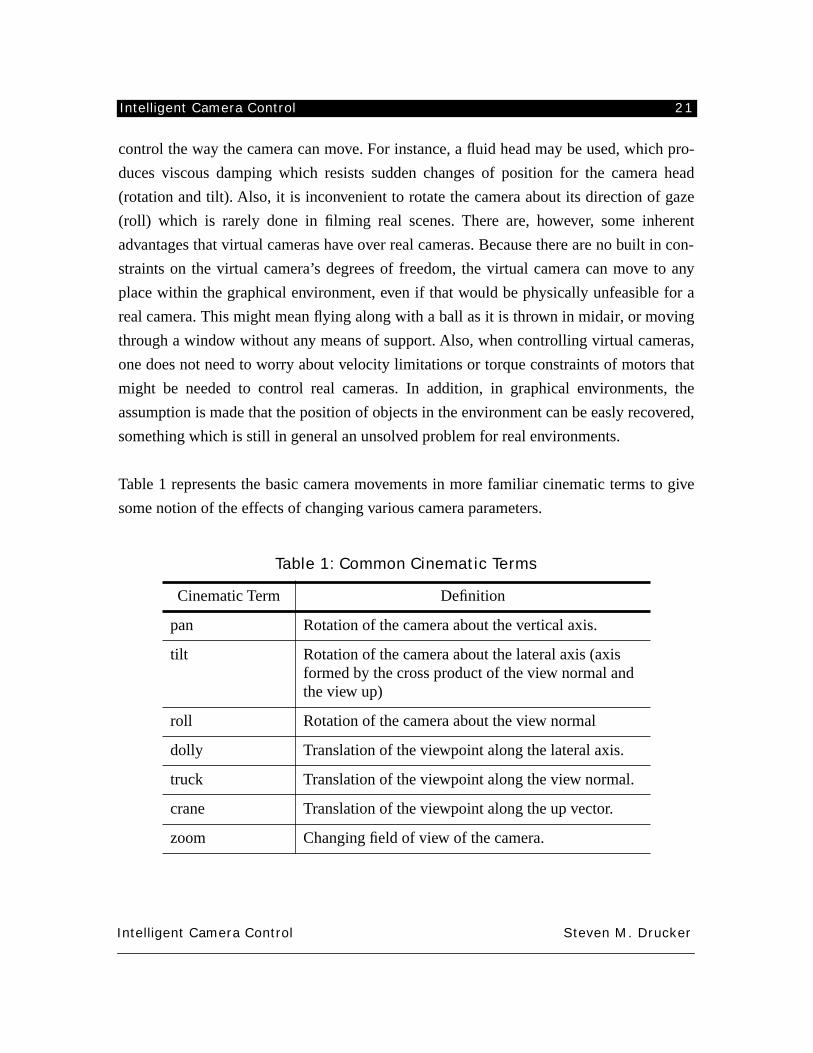
Table 1 represents the basic camera movements in more familiar cinematic terms to give
some notion of the effects of changing various camera parameters.
Table 1: Common Cinematic Terms
Cinematic Term Definition
pan Rotation of the camera about the vertical axis.
tilt Rotation of the camera about the lateral axis (axis formed by the cross product of the view normal and the view up)
roll Rotation of the camera about the view normal
dolly Translation of the viewpoint along the lateral axis.
truck Translation of the viewpoint along the view normal.
crane Translation of the viewpoint along the up vector.
zoom Changing field of view of the camera.
Intelligent Camera Control 22
Intelligent Camera Control Steven M. Drucker
Even though control of the view within graphical environments is crucial, to date only the
crudest methods for specifying the view have been included in most graphic systems. One
common method is to directly control the degrees of freedom of the camera through the
use of dials or sliders. This at least lets the user change the view but is rarely convenient
for achieving any tasks that needs to be performed in a graphical environment. It is espe-
cially difficult to produce any sort of satisfactory presentations because of the difficulty in
specifying a desired motion accurately and continuously.
Another method, perhaps the most common, is to somehow specify the position and orien-
tation of the camera at certain
key
points in time. Motion between those key points is then
described by using an interpolating curve [Barsky83, Gomez84, Kochanek84,
Shoemake85, Stern83]. A variety of different interpolating curves have been used to pro-
duce different motions. Linear interpolation, with sharp first order discontinuities at the
key points tends to look unrealistic. Cubic spline interpolating functions permit the camera
to ease in and ease out of a motion. This kind of motion looks slightly better than linearly
interpolated motion, but is still too regular and contributes to the synthetic, unnatural look
often attributed to computer graphics. However when the key points are interpolated, there
still exists the problem of how the key points are specified in the first place. These methods
are sufficient for only the simplest of camera specifications and movements.
Other methods for moving the camera can include scripting or programming the camera,
for example, to maintain a certain distance from an object as it moves through a scene, or
to move along a complicated path while maintaining the center of interest at a certain
object. These methods can be powerful, but often require programming knowledge and
specific effort for any particular situation [Reynolds88, Drucker92].
Physically based methods try to generate motions for objects based on certain physical
parameters such as mass, inertia, and minimum control effort, and these methods can also
be applied to the camera [Armstrong86, Badler86, Brotman88, Bruderlin89, Girard87,
Isaacs87, Isaacs88, McKenna90, Raibert84, Sturman89, Schröder90, Wilhems87,
Witkin90]. Closely related to these methods are forward simulation systems which model
the effects of a user applied control force and frictional forces to derive the motion of the
Intelligent Camera Control 23
Intelligent Camera Control Steven M. Drucker
camera [Turner91]. This can achieve extremely realistic looking results in terms of what a
real physical camera might do but can be extremely difficult to control to obtain a desired
behavior.
This thesis addresses the creation of a single, common, framework in which to talk about
forms of virtual camera specification within graphical environments based on the task
level concerns of the user. Although I concentrate completely on purely computer medi-
ated environments, the general framework can be applicable to the control of real cameras,
either in motion control systems or for teleoperation systems.
There are a variety of basic reasons for camera movement and placement that will be elab-
orated in this thesis. One reason is for
exploration
; we might wish to discover what’s in a
space, or find out what objects might be nearby. Another reason might be to
perform
some
activity in the space. A camera might show us what it looks like to do that action from
multiple points of view, or the camera can be situated in a way in order to best perform the
activity, or the camera might be able to provide useful, adjunct information. If we’re not
sure exactly what we want to do, another reason to move the camera might be to help
plan
our activity. Planning might involve specifying motion of the camera to present the envi-
ronment to a non-interacting observer or it might involve changing the environment itself.
Planning might necessitate more and different kinds of views of the environment. Finally,
before actually performing the activity, it might be necessary to
rehearse
that activity,
again observing from different points of view in order to better familiarize ourselves with
the process.
The constraint framework that I envision can be embodied as the controlling behavior for a
software agent
which is aware of the environment and the user’s intentions, and has inter-
nal knowledge applicable for controlling a camera. The agent makes decisions based on a
multidimensional terrain, where the goal of the agent at any time is to find the lowest point
of the terrain. If there are several low points on the terrain, techniques are suggested to
bring the system to the lowest point. Barriers exist in this terrain where the camera should
not go. “Mountains” are places where the camera may go, but it is “preferable” to be else-
where. This terrain is constantly evolving over time. The environment changes, thus
Intelligent Camera Control 24
Intelligent Camera Control Steven M. Drucker
changing the underlying terrain. Our goals change from time to time, which also changes
the terrain. The agent may have its own goals which also change the terrain. It is the object
of this thesis to discover how changes in our intentions, changes in the environment, and
external knowledge can be unified into a single underlying framework. In chapter 5 we
talk about a formal mathematical description of camera primitives which can be combined
to form the constraint terrain that determines the agent’s behavior.
The new and original knowledge that is contributed by this thesis is a more thorough
understanding of how humans can control their view
in
computer graphic environments. A
taxonomy of several different application domains is proposed and analyzed to extract
visual tasks to be performed in each domain. Camera primitives are described which can
assist in the performance of those tasks and a framework which allows for the combining
and reusing the camera primitives is presented. The framework is validated through exam-
ining a variety of example application domains.
This problem is of interest to an increasingly large audience since it touches on issues of
research in computer graphics, virtual environments, human machine interfaces, and soft-
ware agents.
2.1.1 Virtual Environments
As described above, graphical environments are essentially a superset of virtual environ-
ments. Virtual environments commonly refer to a graphical environment in which a user is
immersed in the environment, typically by tieing the control of the virtual camera to the
motions of the operator’s head and body through the use of a head mounted display. Navi-
gation through a virtual environment (or in another words, controlling the motion and
placement of the virtual camera) is still a very open issue [Brooks88]. Users often become
lost in virtual environments and may become disoriented or even ill if an interface is not
satisfactory. If virtual environments are to be used to represent or manipulate information,
there must be good ways in which to explore the information space, locate specific infor-
mation, present that information to others, and perform tasks within the environment.
2.1.2 User interface design
Intelligent Camera Control 25
Intelligent Camera Control Steven M. Drucker
User interface design has received a great deal of attention in the research community,
since it is clear that when interacting with a complicated system, a well-designed interface
can greatly affect the ease of use and the effectiveness of the system. In addition to design-
ing an appropriate interface for navigating and exploring a graphical environment, it is
often important to be able to present the information to a non-interactive observer. Inter-
faces, therefore, must be designed with this purpose in mind. This has typically been the
domain of special purpose computer animation systems, with notoriously difficult-to-use
interfaces. The methodology for doing interface design has heavily influenced the structur-
ing of this thesis. By breaking domains down into tasks, and analyzing those tasks, I have
attempted to show that the results in this thesis are generally applicable across a wide
range of domains.
2.1.3 Software agents
A software agent is a method of building an interface which can assist the user in perform-
ing tasks. The software agent may learn by observing a user’s actions, or may encapsulate
knowledge on how to perform a task conveniently. The general area of virtual camera con-
trol is a fine example of how software agents might be used to assist the user in interacting
with a complicated task. The agent can either act autonomously or closely assist a user in
achieving the desired task (these tasks will be defined in chapter 4 of this document). The
actions that a camera agent is capable of are clearly defined in the framework for camera
control.
Don Norman describes several ways in which human reasoning and planning can run into
problems [Norman93].
1. Lack of completeness: In most real tasks, it simply isn’t possible to knoweverything that is relevant.
2. Lack of precision: There is no way that we can have precise accurate infor-mation about every single relevant variable.
3. Inability to keep up with change: What holds at one moment may not apply atanother. The real world is dynamic, and even if precise, complete informationwere available at one point in time, by the time the action is required, thingswill have changed.
4. A heavy memory load: To know all that is relevant in a complex situation
Intelligent Camera Control 26
Intelligent Camera Control Steven M. Drucker
requires large amounts of information. Even if you could imagine learningeverything, imagine the difficulty you’d have finding the relevant materialjust when it is needed. Timely access to the information becomes the bottle-neck.
5. A heavy cognitive/computational load. Even if all the relevant variables wereknown with adequate precision, the computational burden required to takethem all properly into account would be onerous.
The intelligent camera framework that I am describing in this thesis can assist in all of
these areas.
1. Lack of completeness: in an exploratory domain, the system can maintaininformation about the position of all the objects of interest, obstacles, andaccessways. It can give assistance in a variety of forms, from giving a guidein the form of a highlighted path, to moving the user along a path, to immedi-ately transporting the user to the proper place within the database. Themuseum application described in section 6.1 shows an example of this styleof assistance.
2. Lack of precision: the system can place the user at the exact point that meetsthe conditions specified by the user. The visibility assistant described in sec-tion 6.5 demonstrates an example of this style of assistance.
3. The assistant is ideal for dynamic environments. If the user can express inten-tions (often best as constraints), the system can maintain those constraints asthe environment changes. The mission planner (section 6.2) and the footballgame (section 6.4) are both examples of camera assistance for dynamic envi-ronments.
4. Heavy memory load: The assistant can encode not only information about theenvironment, but rules for presenting the environment. The conversationfilming agent, described in section 6.3, shows one way of encoding thoserules.
5. Heavy cognitive/computational load: Not only can the assistant perform diffi-cult computation tasks to achieve the intentions of the user, but it can auto-mate repetitive tasks, thus freeing the user to perform other actions. This isdemonstrated in nearly all the examples for chapter 6.
Intelligent Camera Control 27
Intelligent Camera Control Steven M. Drucker
2.2 Overview of the solution proposed
The general strategy taken in this thesis will be the following:
• A taxonomy of interactive graphical domains is presented and a list of the req-
uisite visual tasks associated with them.
• Camera primitives are derived to assist the user in performing the visual tasks
described in the previous step.
• A framework which can combine the camera primitives is presented and dis-
cussed. It is important to note that this framework is intended to be general and
extensible.
• Interfaces are built on top of the framework for a set of representative
domains. This will provide an opportunity to explore some extremely different
kinds of user interfaces that can be developed on top of the underlying frame-
work and demonstrate the general utility of the framework.
• Evaluations of the resultant applications will be discussed to indicate the
effectiveness of the proposed camera framework.
2.2.1 Framework
The essential idea is that the intentions of a human user with respect to a given task can be
formulated in terms of mathematical constraints. By providing a framework of constraints
for camera specification I have created a domain independent language for building visual
interfaces. It needs to be shown that this “language” is general, efficient, and robust.
2.2.2 Generality
Generality will be shown by looking at the virtual domains in which a camera needs to be
applied. We need to show that the domains we investigate are a sufficiently representa-
tional subset of all possible domains. Obviously there is no way of enumerating all possi-
ble domains, but at least a sufficiently large set can be spanned. Within each domain, a
number of representational tasks that would naturally be performed within the domain are
described. For each of those tasks, it is shown how they can be conveniently expressed in
the form of the constraint language that I am suggesting.
Intelligent Camera Control 28
Intelligent Camera Control Steven M. Drucker
2.2.3 Efficiency
Efficiency issues must be explored from two sides: implementation/algorithmic concerns
and appropriateness concerns. To address the algorithmic issues, it needs to be shown that
the kinds of constraints are algorithmically sound. Problems and methods of dealing with
local minima must be explored, computational efficiency and scalability must be dis-
cussed, and trade offs between expressing constraints in different ways should be identi-
fied. The appropriateness issue is more closely related to whether choosing constraints in
general (and the specific constraints that are chosen) can adequately express the kinds of
tasks that need to be performed. The classic example here is the Etch-a-Sketch problem. In
the toy Etch-A-Sketch, the knobs let you move horizontally and vertically which are all
right for certain tasks, but completely inappropriate for trying to draw a diagonal line. In
this instance, a better solution might be one that controls the angle of a line and one that
actually draws the line. How can we show that the constraints that we have picked are
appropriate for expressing the tasks that we need to do? That question is answered by
looking at the wide range of interfaces that has been generated and showing the different
styles of interaction that can be supported.
2.2.4 Robustness
From an algorithmic standpoint, we need to examine when the system breaks or produces
results that are not satisfactory. How much special purpose coding needs to be done in
order to achieve more correct results. How easy is it to produce conflicting constraints and
what can be done when this happens? These issues are examined in chapter 7.
The five applications that are examined in this thesis are the following: a virtual museum,
a mission planning system, a conversation filming agent, a visibility assistant, and a virtual
football game. These tasks represent a wide sampling of different styles of interaction
which have different visual task requirements. They are described in detail in chapter 6.
Background and related work 29
Intelligent Camera Control Steven M. Drucker
CHAPTER 3. BACKGROUND AND RELATED WORK
This chapter will discuss relevant background from the areas of computer graphics, con-
straint based systems, optimal control, robotics, teleoperation, human factors, user inter-
face design, human perceptual capabilities, and cinematic style . Some general references
that have been extremely useful are as follows: [Foley82, Foley90] for a general introduc-
tion to computer graphics; [Carroll91, Laurel90, Baecker87] for some essays in human
computer interaction; [Ellis91] for studies of camera control in virual environments and
teleoperator; [Fletcher80, Gill81, Press88, Rogers76] for numerical algorithms and opti-
mization techniques; [Arijon76, Katz88] for film directing techniques.
3.1 Computer Graphics
Camera movements have long been studied in many different contexts within the field of
computer graphics; for animation; for exploration/manipulation, or for presentation. I will
briefly discuss work in each area, and touch upon how this work contrasts to the existing
body of literature.
3.1.1 Interpolation
Early work in animation is devoted to making the movement of the camera continuous and
developing the proper representation for camera movements along a path [Barr92,
Barsky83, Bartels87, Gomez84, Kochanek84, Shoemake85, Stern83]. These works are all
devoted to giving the animator greater control in creating smooth movements and finding
ways to interpolate between user specified keyframes. Although generating spline curves
for camera movement can produce smooth paths, it can be difficult to relate the move-
ments of the camera to objects in the environment, or even to find appropriate keyframes
Background and related work 30
Intelligent Camera Control Steven M. Drucker
in the first place. Also, such kinematic specifications for paths tend to produce movements
that are physically impossible and unsettling to a viewer. It has also produced an unmistak-
able style for computer animations that is not necessarily attractive. In cinematography, a
much higher emphasis is given to the composition of a single frame rather than moving the
camera through the environment. Both [Barr92, Shoemake85] discuss the benefits of rep-
resenting object orientation (including cameras) as quaternions. Quaternions have the
advantage of having the same local topology and geometry as the set of rotations (untrue
for euler angles). They are a compact representation (only 4 numbers), and only have one
constraint (unit-length). There is the problem of dual-representation in that any rotation is
represented by two quaternions, one on either side of the hypersphere.
Brotman and Netravali [Brotman88] introduced a method for using optimal control to
interpolate between keyframes in a dynamically realizable method while trying to mini-
mize control effort. Their work produced subjectively more appealing interpolations. The
previously mentioned discussion in [Barr92] extends interpolation of orientations into
including velocity constraints through basic optimization methods. They advocate the use
of packaged optimization routines because of their robust stopping conditions on an opti-
mal solution.
3.1.2 Physical Simulation
Physical simulation can produce far more natural looking movements than keyframe spec-
ification. It has been used in a variety of systems for animating the motion of characters
[Armstrong86, Badler86, Bruderlin89, Girard87, Isaacs87, Isaacs88, McKenna90,
Raibert84, Sturman89, Schröder90, Wilhems87,Witkin90]. It has even been used for the
simulation of camera motion by using forward simulation of a camera with mass, friction,
and viscosity [Turner91]. One problem with all dynamic simulation systems is that it is
difficult to get the system to behave in a desired manner.
3.1.3 Optimization
One solution to such a problem is to use optimization techniques. There is a large history
of constraint techniques for computer graphics starting with diagramming and 2D simula-
tion systems. Sutherland’s pioneering Sketchpad paper [Sutherland63] allowed users to
Background and related work 31
Intelligent Camera Control Steven M. Drucker
specify constraints between objects and the system propagated and relaxed constraints
until a solution was found. The ThingLab system [Borning79] was designed as a simula-
tion laboratory for experiments in physics and mechanics. Thinglab had built in rules for
quickly satisfying constraints procedurally if possible and by relaxation if the other
approach was not successful. Several attempts to aid in drawing and manipulation have
used constraint based systems including Juno [Nelson85], Snapdragging [Bier90], Briar
[Gleicher92], Figuremaker [Kalra90].
Constrained optimization techniques have been used extensively for three-dimensional
animation systems too.Witkin and Kass [Witkin88] use optimization over both space and
time to find optimal paths between initial and final conditions for rigid bodies. They use a
similar optimization procedure (Sequential Quadratic Programming) to explore the space
of solutions iteratively. One limitation of this work is that the complexity growth of the
problem limits the length of time over which it is useful. In addition, because of the highly
non-linear nature of the constraints and objectives, many numerical routines do not con-
verge. Cohen [1992] extended this work to allow for greater user interaction during the
solver stage. He also represents the contraints and objective functions in compact form
(splines) which allow for greater robustness in the solver. The work in this thesis is in
some ways very similar to these approaches. I use Sequential Quadratic Programming to
explore space for an optimal position of the camera subject to user specified constraints.
The user can assist the optimization by halting it, and restarting it with different initial
conditions. Although I usually use the optimization to find a single static solution for the
camera, certain techniques produce a time series position for the camera (notably the path
planning and visibility constraints). Extensions to this thesis might involve the inclusion of
physically based constraints over time for the camera in the manner of the space-time con-
straints of Witkin and Kass or Cohen.
Animation systems which incorporate kinematic or dynamic constraints have included
[Badler86, Barzel88, Isaacs87, Isaacs88, Lathrop86, Philips90, Ridsdale87, Witkin87].
Dynamic constraints have been introduced by Barzel and Barr [Barzel88] which treat con-
straints as a physical system with forces that are introduced to satisfy the constraints.
Other methods, based on penalty forces formulated as energy constraints have been used
Background and related work 32
Intelligent Camera Control Steven M. Drucker
to make physically realizable systems with constraints [Witkin87, Terzopoulos87, Platt88,
Kalra90, Pentland90].
Kass [Kass91, Kass92] proposes a general system for graphically combining functions in a
dataflow paradigm and then using interval arithmetic or optimization methods to come up
with a solution to the problem. Kass’s system includes a number of well thought out fea-
tures for dealing with this type of problem including computing the derivatives symboli-
cally and then compiling the derivatives for efficient evaluation during the optimization
process.The advantages of his system are that the system is extremely general and can be
applied to a wide variety of problems in graphical systems. His system does not perform
any global optimization (since it is nearly impossible to do so on general problems). He
shows one example with his system which derives the camera parameters based on the
known position of 4 projected points. His system is not designed to specifically deal with
camera placement problems though certain modules can be built based on combining the
functions he provides. Some work in this thesis has origins in the same notions as Kass’s
work. Convenient specification of an optimization problem in terms of a graphical pro-
gramming environment is shown in the section about the virtual football game (see section
6.4).
The system proposed in this thesis relies on constrained optimization techniques to
achieve the specified goals for a static position or for limited dynamic movement of the
camera. The optimization conditions can be defined as energy constraints, or as strict
boundary constraints. In general, however, the camera is not treated as a physical object
and not dynamically simulated, since a more general optimizer is being used.
3.1.4 Virtual Environments & Scientific Visualization
With the advent of virtual environments and related 3D interactive worlds [Adam93,
Bishop92, Blanchard90, Blau92, Earnshaw91, Earnshaw93, Esposito93, Fisher86,
Greeenberg74, Zyda92], a great deal of effort has been spent on presenting convenient
methods through which users can change their view of an object or the world. Metaphors,
as discussed in [Ware90] provide the user with a model that enables the prediction of sys-
tem behavior given different kinds of input actions. A good metaphor is both appropriate
Background and related work 33
Intelligent Camera Control Steven M. Drucker
and easy to learn. Some examples of metaphors are the “eyeball in hand” metaphor, the
“scene in hand” or “dollhouse” metaphor, and flying vehicle control.
In the “eyeball in hand” metaphor, the user can use a six DOF device to position and orient
a camera by directly translating and rotating the input device. Ware found this method
somewhat awkward to use but easy for users to learn. The “scene in hand” metaphor lets
the user rotate and translate the scene based on the position of the input device. This was
found to be very convenient for hand sized objects, but nearly impossible to use for navi-
gating inside closed spaces. Another scheme discussed by [Ware90] was to simulate con-
trol of a flying vehicle. The user’s position and orientation affected the velocity and
angular velocity of the camera viewpoint and direction of gaze. This metaphor was quite
appropriate for navigating through space, but difficult to examine all the sides of a single
object since it was difficult to maintain the gaze on a particular object while moving. 3D
input devices such as a Polhemus isotrack system or a spatial systems Spaceball enable the
user to specify 6 degrees of freedom simultaneously, and simulations of these devices can
be done using only 2D devices [Chen88, Evans81]. Some of the problems inherent in
using these devices are the noise which is inherent in user movements and the number of
degrees of freedom which must be simultaneously controlled.
Mackinlay et al [Mackinlay90] discuss the problem of scaling the camera movements
appropriately. They developed methods to include both the ability to select an object of
interest and to move exponentially towards or away from the object. By selecting ‘point of
interest’, the authors can reorient the camera to present a maximal view of the desired
object. In this way, the degrees of freedom are restricted and the user can concentrate more
on the task of navigating through the environment based on what is in the environment.
Brooks et al [Brooks86, Brooks88] and Airey [Airey90] develop several different methods
for moving around architectural simulations including steerable treadmills or shopping
carts with devices to measure the direction and speed of movement.
Blinn [Blin88] suggested alternate modes of camera specification for planetary flybys
based on four separate requirements. In general, the goal is to place an object in the fore-
Background and related work 34
Intelligent Camera Control Steven M. Drucker
ground (the spaceship) and an object in the background (the planet), and have the system
interpolate interesting views while the spaceship moves. One mode is the standard view
formulation achieved by specifying the view point of the camera, the view normal (gaze)
of the camera, and the view up vector. Another mode is to find a position based on the cur-
rent gaze (I’m looking here, where should I stand?). Another is to find a gaze based on the
current position, (I’m standing here, where should I look?). Finally, the last mode attempts
to find both the view position and the normal based on the task specification. The approach
that Blinn uses involves representing the unknown vectors in terms of vectors that are
known. The idea for Blinn’s work is in some ways a basis for this thesis since his concept
of camera placement is based on achieving a particular goal, however, his solution is
rather specific to the situations that he describes. His work can be expressed within the
framework of this thesis in a clear, succinct fashion (see chapter 5).
The above works all show that different interfaces are appropriate for different user
requirements. No one interface is ideally suited for all tasks, and a common underlying
structure on top of which several different metaphors can be implemented would give the
user a powerful tool to interact with 3D environments. Another important point empha-
sizes the ability to select object of interest within the environment. I have expanded on this
by allowing the user to specify constraints on the camera according to general properties
of the environment.This lets the user manipulate the camera motion based on the actions
within the environment, which is, after all, the goal in the first place.
Furthermore, while direct manipulation has certain advantages in interactive systems,
there are several deficiencies. It is not necessarily good for repetitive actions, and any
action that requires a great deal of accuracy, such as smooth movement for cameras, is not
necessarily suited to input using one of the metaphors suggested in the preceding para-
graphs. There obviously need to be ways to manipulate the environment that is uncoupled
with direct control of the degrees of freedom of the camera.
3.1.5 Automatic Camera Control
One method of automatically controlling the camera was suggested in [Philips92] for use
in manipulations in the Jack system. The camera was positioned at a visible location at an
Background and related work 35
Intelligent Camera Control Steven M. Drucker
appropriate angle for manipulation using specific kinds of controllers.
Karp and Feiner [Karp90] describe a system which automates the creation of presentation
based on a heuristic reasoning process. They use certain user specified goals along with a
rule base to decompose the problem first into a series of sequences, and then into a series
of shots. Finally, they compose each shot and then patch up the resultant sequence using
other rules. They do not specify how they deal with any camera specification at the shot
level other than fairly straightforward lookat types of constraints, or specific solutions to a
number of issues that they have enumerated. Their system could be used on top of a more
sophisticated shot creation mechanism such as the one described in this thesis. This thesis
uses a more straightforward user specified template approach with a sophisticated con-
straint mechanism to attempt to capture cinematic rules as opposed to a complicated rule
base. Each approach has distinct advantages, one being essentially top down, while the
other being bottom up. My focus (so to speak) is on the composition of the image rather
than an automatic composition of an entire narrative.This work expands on their notion of
incorporating cinematic rules for automatic presentation, but can be considered an under-
lying framework for a system such as theirs. Although I make extensive use of cinematic
rules for designing the constraints themselves, these rules are not used for any actual auto-
matic presentation. Automatic presentation in this thesis is limited to prototypes or tem-
plates that are designed by the user to accomplish certain tasks. The user of the system or
the system can autonomously use these prespecified templates for controlling the camera.
Seligman and Feiner [Seligman91] use visibility constraints not to control camera place-
ment, but to affect the rendering style (cut-aways, transparency) of the resultant image.
The CINEMA system [Drucker92] was an initial attempt at unifying these disparate
notions of camera control under one system. It was a method of procedurally specifying
the movement of a camera based on objects in the environment.It shared the notion of eas-
ily writing scripts for the control of animations with [Reynolds82]. Problems of the CIN-
EMA system are in part what drives the primary thrust of this thesis – the system was not
sufficiently reusable or generalizable. Also, there was too much of an emphasis on pro-
gramming the motion of the camera when it is clear that the average user does want to pro-
gram to interact with a graphical environment.
Background and related work 36
Intelligent Camera Control Steven M. Drucker
After experiencing some of the problems with camera control in the CINEMA system, it
was decided that a solution to all of the problems was to formulate camera control in terms
of constraint satisfaction. Gleicher and Witkin describe constraint satisfaction for camera
control in their paper Through the Lens Camera Control [Gleicher92]. However, they do
not attempt to generalize their work to any context outside of directly manipulating the
camera. In addition, their system has a number of limitations. Their system works purely
in a differential fashion for camera parameters which makes it only appropriate for local
movement. They state that they feel that local movement is appropriate for camera control
in a computer graphic system which may be true for certain manipulation examples but is
generally untrue in most cinematic operations. In fact, it has been stated, that nearly 70%
of all shots in most films involve no camera movement whatsoever. Their method, which
they call Through the Lens Camera Control (TTL camera control) is based on the notion
that the change in the projection of a world space point can be based on changes in the
camera parameters. Thus by calculating a Jacobian matrix which relates these two
changes, a desired local change in the projected point can be achieved. Care must be taken
when computing the pseudoinverse of the Jacobian to guarantee stable control of the cam-
era through singularities in the camera parameters (i.e. points where small changes in the
camera parameters will have an enormouse affect on the resultant change of the image
space position of a point).
3.2 Robotics
3.2.1 Pathplanning
A camera can be considered as a simple robot. Thus many techniques developed for the
robot motion planning field may be adapted for planning the movement of the camera.
Some basic differences include the nature of the camera gaze which can be considered as
an infinitely long upper manipulator. The motion planning problem can become arbitrarily
more difficult as true three dimensional path planning can be incorporated. This thesis
builds upon conventional robot path planning methodologies for the development of the
constrained optimization path planning algorithm [Arkin89, Asseo88, Barraquand89,
Braitenberg84, Brooks82, Hopcroft94. Kant86, Schwarz83, Thalmann88, Lozano-
Perez70]. An extensive discussion of robotic motion planning algorithms is available in
Background and related work 37
Intelligent Camera Control Steven M. Drucker
[Latombe90] and has been of great use in the algorithms used for this thesis. Some of this
work is discussed in greater detail in appendix 1.
3.2.2 Sensor Positioning
Robotics literature is also a source for approaches to camera positioning for robot vision
tasks. Tarabanis and Tsai [Tarabanis92] review several systems for sensor planning for
robotic vision. In general the requirements involve placing a camera and an illuminator in
order to recognize or detect features of an object. The systems they describe often need to
concern themselves with issues not present in the system presented in this thesis including
depth of field, resolution of image, and illuminator placement. They state that an automat-
ically planned system allows for the following: a robust solution satisfying the task
requirements even in the presence of uncertainty; parameters can optimize the sensor out-
put with respect to a given task criterion; and that a sensor-based system can become adap-
tive automatically reconfiguring itself to accommodate variations in the workspace. In
general, the types of constraints considered in these systems are visibility constraints, field
of view constraints (making sure the object is not clipped by the field of view of the cam-
era), depth of field constraints (object is in focus), and pixel resolution of the object. They
also look at radiometric constraints such as illuminability, dynamic range, and contrast.
Since one of the primary concerns of automatic vision systems is to recognize an object or
features of an object, a great deal of the work to date involves determining what are salient
features of an object, and what views are appropriate to highlight those features (make
sure they are illuminated properly or shown to the camera in silhouette). They describe 5
main systems: work done at SRI [Cowan87]; the VIO system [Niepold80]; the HEAVEN
system [Sakane81]; the ICE system [Yi84]; and the MVP system [Tarabanis85]. Some
methods use the calculus of variations to derive the camera position from images
[Horn86]. Other methods have been used to position objects themselves for display
[Kamada88]. In general, most of the systems formulate the problem in terms of constraints
that need to be satisfied and finding solutions which satisfy those constraints. Several of
the systems use a generate and test approach to the problem, while the MVP system using
a global optimization solution. In addition, when the constraints are expressed analytically,
a more efficient solution process can be used. The work presented here is on a similar level
to the system presented in this thesis, yet the types of constraints required are somewhat
Background and related work 38
Intelligent Camera Control Steven M. Drucker
different and more limited.
In addition, reactive planning in robotics as explored by [Brooks86], and [Maes90,
Maes91] can be exploited in complicated domains with moving objects where traditional
path planning methods are not applicable. Reactive agents were a motivating force behind
the development of the camera framework presented in this thesis. By allowing certain dif-
ficult parts of interaction to be supported by an agent style interface, the user is able to
concentrate more on the task at hand.
3.3 Teleoperation
Closely related to robotics is teleoperation and supervisory control [Sheridan87,
Sheridan88, Sheridan92]. Visual displays are of overriding importance in teleoperation
and supervisory control because, “A fundamental issue in the design of the man-machine
interface is the use of visual feedback. Visual feedback is normally the primary source of
feedback information” [McKinnon91].Das [Das89] systematically compared some auto-
matic view selection techniques in the context of a control a redundant telemanipulator.
Four different sets of trials were performed to assess user performance. In the first, the user
was allowed to select different views by flying the virtual camera around the workspace.
In the second set, the virtual camera was fixed to the based of the telemanipulator, some-
what like viewing out of the cockpit of a plane to which the manipulator was attached. A
third set fixed the virtual camera location to the side of the task. The fourth set of trials
automatically selected a “best” view that found a viewpoint for the camera that provided
an orthogonal projection of all the distances between the telemanipulator, two obstacles,
and a goal. The “best” view place the camera at a point which was the intersection of 3
planes, each of which was a bisector of the line connecting the end-effector of the manipu-
lator with the obstacles or the goal respectively. Performance was best when the user was
allow to select between multiple views. Next base was the automatically selected view.
The worst performance was using the out of the cockpit view. The best view algorithm can
be thought of in the context of this thesis as optimizing the camera position subject to three
constraints, maximize the angle of projection for each of the goal and obstacle objects. An
important lesson taken from Das however, is that users need to have some sort of control
over the selection of views to perform well.
Background and related work 39
Intelligent Camera Control Steven M. Drucker
3.4 Human factors & Human Computer Interaction
Extensive human factors testing has been done to determine the effects of different forms
of visual displays on human perception and task performance. The view that a systematic
approach begins with a task analysis [Brooks91, Berlyne67, Fleishman84, Miller63,
McCormick76, Newell78, Whiteside85] is supported in this thesis. In fact, Brooks goes so
far as to say the following:
...from the perspective taken here, developing good descriptions, particularlygood taxonomy that adequately differentiates artifacts, is important in its ownright because it is a useful, possibly necessary, precursor to appropriate formal-ism and, in turn, to technical theory [Brooks91].
Chapter 4 details the tasks analysis that led to the basic structure of the thesis and chapter
6 describes the way we can go from a basic task analysis to a prototype of an interface.
Current theories in human computer interaction support the iterative nature of design for
interfaces. If the interfaces are built on top of a consistent cognitive structure, they can be
made to greatly enhance user understanding and facility [Bass92, Baeker87, Carroll87,
Carroll88, Cotterman89, Landauer87, Norman87, Norman88, Norman90, Norman93,
Schneiderman92, Zeltzer85, Zeltzer91, Zeltzer92]. In addition, with the benefit of a con-
sistent underlying framework, different styles of interaction can be designed and supported
including conversational interfaces [Bolt87, Foley87, Nickerson87, Negroponte89,
Schmandt83], theatrical interfaces [Laurel86], direct manipulation [Hutchins86, Boies89,
Schneiderman83], and visual programming languages [Cypher93, Haeberli88, Kass92].
This thesis has made use of many of the notions of these alternative interface styles,
including an immersive environment with voice and gestural recognition for the Mission
Planner and a visual programming environment for combining and sequencing camera
primitives.
3.5 Human Perceptual Capabilities
Human perceptual issues also must be examined in any system that needs to present infor-
mation effectively to an end-user. Cornsweet in particular provides an excellent introduc-
Background and related work 40
Intelligent Camera Control Steven M. Drucker
tion to human visual perception in [Cornsweet70]. Hochberg and Brooks present an
extensive examination of human perception of motion pictures in [Hochberg87] which has
been of particular use in this thesis.
Hochberg and Brooks identified three different theoretical mechanisms that might account
for the observer’s comprehension of change in camera position across temporal sequences
of film. The first mechanism is closely tied to the perception of apparent motion of objects.
This phenomena involves the discrete changes of the position of an object or objects
between frames. The perception of apparent motion breaks down based on limits for the
distance between the positions of the objects and the intertemporal spacing of the stimuli.
These limits have been identified experimentally and can be used in part as a basis for the
maximum camera movements per frame allowed in many of the demonstrated applica-
tions.
Another mechanism deals with overlapping cuts of a scene. This theory proposes that
viewers integrate the successive views by extracting a transformation between the changes
of position of familiar objects within the scene. This might explain one of the reasons that
people often become disoriented and lost in the sparsely populated virtual environments. If
no identifiable landmarks exist, then the perception of the direction of motion of the cam-
era reduces to chance. Attempts have been made in this thesis to enrich the environments
with identifiable objects.
The last mechanism for visual perception of camera position is based on the concept of a
cognitive map. Cognitive maps form the basis of a style of architectural design expounded
in [Lynch60] and [Passini92]. It is not immediately clear whether the cognitive map is
symbolically represented or spatially represented, but in either case, viewers are able to
build maps from successive views of an environment, and can use the map to stay oriented
within the environment. One way to utilize cognitive maps is to enable explicit maps for
the interfaces designed in this thesis. In addition, the maps can be dynamic maps which
adjust to the user’s position and orientation within the environment.
Background and related work 41
Intelligent Camera Control Steven M. Drucker
3.6 Cinematography
Art has often been an effective communication tool and can serve as a guideline to build-
ing effective interfaces. An extensive examination of the use of perspective in communica-
tion is discussed in [Kubovy88]. Even more appropriate to this thesis is presentation style
as it has developed in the field of cinematography. Several books have been extremely use-
ful for gaining an understanding of the film medium. Notably, Arijon [Arijon76] has a
straightforward, deconstructivist style, with descriptions on filming any of a large number
of situations. Some might consider his descriptions to be simplistic, but they are the per-
fect basis for deriving a large class of camera primitives. This class of primitives which I
call projection constraints involve the placement of the camera based on the projection of
an object onto the screen. These include issues of framing objects so that their relative
sizes are appropriate, placing the camera so that the projected motion of objects on the
frame is consistent across edits, and being able to control the projected gaze vectors of
characters in the environment based on the placement of the camera. These constraints are
described in greater detail in section 5.3. In addition to the work of Arijon, cogent explana-
tions of cinematic techniques and style given in [Katz88, Katz92, Kawin92]; for photogra-
phy [Cheshire94]; for editing [Reisz68, Thompson93]; and for cinematic theory
[Nilsen61, Isenhour75, Burch81] have all been useful.
There have been some previous limited attempts at incorporating cinematic style in com-
puter graphic systems including the excellent discussion concerning animation techniques
by Lasseter [Lasseter87]. Previous work also includes techniques for special effects
[Thalman86], the aforementioned automatic planning systems of [Karp90, Seligman91]
and analysis [Potel76].
Taxonomy of Interactive Domains 42
Intelligent Camera Control Steven M. Drucker
CHAPTER 4. TAXONOMY OF INTERACTIVE DOMAINS
4.1 The Problem Domain
The first requirement of the thesis is to generate a clear definition of what visual tasks a
user might try to perform in a graphical environment, and what characteristics need to be
associated with a camera to assist the user in accomplishing those tasks. I will enumerate a
list of prototypical tasks, that will help drive the definition of an intelligent camera. This
list is meant to be broadly representative of the kinds of visual tasks that users might wish
to perform in a graphical environment. This is by no means a complete list of tasks but
rather a list that will help generate ideas as to how an intelligent camera can aid a user.
Also, solutions will not be proposed for all tasks, but rather a categorization of the tasks is
attempted so that a systematic solution can be described. For each category, examples will
be given, and a list of of characteristics for the camera control will be enumerated.
Except where stated otherwise, the user will not be changing the environment, but only
acting as an observer. This restriction, while limiting, will help focus the analysis on the
manipulation of the user’s view and not on the means of interacting with objects in a envi-
ronment. An overriding consideration in all these task domains is that the environment is
perceived by the visual system of the operator and thus care must be taken so that the out-
put of the system is well within human psychophysical abilities and expectations
[Cornsweet70, Hochberg78].
This list in table 2 of interactive domains was arrived at through examining several papers
[Adam93, Bishop92, Blanchard90, Blau92, Earnshaw91, Earnshaw93, Esposito93,
Taxonomy of Interactive Domains 43
Intelligent Camera Control Steven M. Drucker
Fisher86, Greeenberg74, Zyda92, Bass92, Baeker87, Carroll87, Carroll88, Cotterman89,
Landauer87, Norman87, Norman88, Norman90, Norman93, Schneiderman92, Zeltzer85,
Zeltzer91, Zeltzer92, and others], and several brainstorming sessions with practitioners in
the field. Different graphical applications were classified into one of four domains. This
domains seem to encompass most of the different types of activities which people perform
in interactive graphical environments.
4.2 Terminology
Word usage tends to be confusing when trying to formulate a taxonomy. One would like to
use words that bring about instant understanding, but certain words are so overloaded that
they might be misinterpreted. I use several terms and provide definitions for each of them.
In general, I try to follow the formal dictionary definitions, but sometimes that is not possi-
ble since I could find no better word to describe what I mean. Briefly, here is a list of the
terms for the taxonomy: environment, domain, application, application task, generic task.
The highest level of the hierarchy is referred to as a
domain
. The
domain
describes the
basic endeavor that is being attempted. Within each of the domains are
applications
, and
each of those
applications
is composed of specific application
tasks
. There are several
generic
tasks
that are pertinent to many
applications
within many
domains
.
4.3 Taxonomy
To begin with, I broadly classify four primary domains in which most activities lie: explo-
ration, planning, rehearsal, and control.
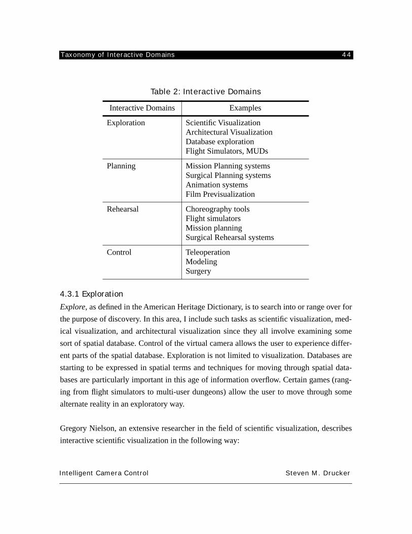
Taxonomy of Interactive Domains 44
Intelligent Camera Control Steven M. Drucker
4.3.1 Exploration
Explore
, as defined in the American Heritage Dictionary, is to search into or range over for
the purpose of discovery. In this area, I include such tasks as scientific visualization, med-
ical visualization, and architectural visualization since they all involve examining some
sort of spatial database. Control of the virtual camera allows the user to experience differ-
ent parts of the spatial database. Exploration is not limited to visualization. Databases are
starting to be expressed in spatial terms and techniques for moving through spatial data-
bases are particularly important in this age of information overflow. Certain games (rang-
ing from flight simulators to multi-user dungeons) allow the user to move through some
alternate reality in an exploratory way.
Gregory Nielson, an extensive researcher in the field of scientific visualization, describes
interactive scientific visualization in the following way:
Table 2: Interactive Domains
Interactive Domains Examples
Exploration Scientific VisualizationArchitectural VisualizationDatabase explorationFlight Simulators, MUDs
Planning Mission Planning systemsSurgical Planning systemsAnimation systemsFilm Previsualization
Rehearsal Choreography toolsFlight simulatorsMission planningSurgical Rehearsal systems
Control TeleoperationModelingSurgery
Taxonomy of Interactive Domains 45
Intelligent Camera Control Steven M. Drucker
as related to those applications where the user interacts with the model and drivesthe simulation in hopes of “gaining new insight” or “creating a new design.” Theprimary interface for this interaction is the visual images viewed by the user andthe subsequent input based upon the user’s perception and interpretation of thoseimages. The emphasis here is on applications which involve physical models inthree dimensional space [Nielson91].
Thus scientific visualization involves the end user gaining an understanding of the impor-
tant information, events, and relationships implicit in high bandwidth, possibly multi-
dimensional datasets. In scientific visualization, as well as medical visualization, and
architectural visualization, the user must somehow achieve a correspondence between the
information presented to him through the interface, and an internal representation of the
spatial domain [Springmeyer92]. For some of these applications, there exist natural ana-
logs for the information that is presented. For others, however, the information itself must
be transformed and represented in a manner that can be understood by the user.
In medical visualization specifically, many feel that the imaging modalities of transmis-
sion and emission tomography, magnetic resonance imaging and ultrasound are revolu-
tionizing medicine. Pernkopf [Pernkopf87] feels that “improved 3D visualization
techniques are essential for the comprehension of complex spatial and, in some cases, tem-
poral relationships between anatomical features within and across these imaging modali-
ties.”
In general, for these applications, the operator should be able to quickly
orient
himself in
the environment, and
navigate
conveniently from one part of an environment to the other.
Sometimes, the operator may be explicitly looking for a certain aspect of the environment,
in which case the system is primarily used for
navigation
through the environment from
one point to another. At other times, the user may be
wandering through
the environment
with no particular destination in mind. Finally, the operator sometimes wishes to
examine
a certain aspect of the environment.
Some specific examples of applications in the exploratory domain include the following:
Large data set exploration
: Many three-dimensional applications in scientific visualization
Taxonomy of Interactive Domains 46
Intelligent Camera Control Steven M. Drucker
consist of the study of multidimensional physical phenomena. The scientist is free to fly
within the simulation and therefore to focus interest on any part of the simulation, to study
it in detail, or to allocate supercomputer time for a more precise simulation.
Architectural walkthrough
: Systems such as these allow the user to explore buildings that
are designed but not yet constructed, or buildings that no longer exist. An object of such a
system is to visualize a building to permit the architect to prototype the building and to
discuss with his client on the detailed desiderata for it. Specific tasks within an architec-
tural walkthrough might be to examine the artificially constructed environment for emer-
gency exit routes for obstructions; or to examine visibility paths from one point to another;
or a human factors analysis of the environment could be performed.
Weather simulation
: A simulation of a hurricane or a tornado involves the flow of air in 4
dimensions (space as well as time). The task would be to understand what circumstances
lead to the formation of a hurricane by observing those air flows from different viewpoints
and with different tools that might help analyze how the air flows change.
Some other examples include
molecular analysis, medical imaging,
and
exploration of
data received from satellite pictures.
In general, the visual requirements for performing exploratory tasks are related to moving
through the environment, and being able to retrieve the spatial position of the virtual cam-
era within the environment, and the relative positions between objects within the environ-
ment.
1. Change the viewpoint and direction of gaze in a fashion which makes senseto the user and is not disorienting or distracting. To do this, the camera mustobey some restrictions discussed in section 3.5.
2. Allow the ability to specify separate points in the environment for convenientnavigation between them. By convenient, I mean to limit the amount of com-putational or cognitive effort that the user needs to make.
3. Allow quick recovery of information about current position and orientation ofthe user. This is particularly crucial because of the tendency for users to getlost and disoriented in a virtual environment [McGovern91].
Taxonomy of Interactive Domains 47
Intelligent Camera Control Steven M. Drucker
4. Allow efficient recovery of information about the relative positions and orien-tations of objects within the environment.
5. Constrain the movements of the user in a fashion that makes sense for thegiven domain (don’t walk through walls in an architectural domain, keep cer-tain objects in view in a scientific visualization domain). This is related to thefirst item because movement through obstacles can be very confusing to anobserver. This involves collision detection and to a certain extent, the simula-tion of a camera as a physical object.
For a detailed analysis of one specific application in the exploration domain, see the
description of the Virtual Museum in chapter 6.
4.3.2 Planning
“To plan” is defined as “to formulate a scheme or program for the accomplishment or
attainment of something.” In this area I include such diverse applications as surgical plan-
ning and simulation; mission planning & rehearsal; and film previsualization.
A planning task might consist of figuring out how to manipulate some objects within an
environment, or might consist of specifying the motion of the camera itself for presenting
the results to a non-interactive observer.
In describing one such task for orbital planning, Don Eyles of Draper Laboratories says
the following:
What is necessary is the ability to plan and then to monitor spatial operationswhich may be hard to see and hard to visualize. For this case, the ability toassume a God’s-eye view and follow the orbits leading to rendezvous, to flyalongside in a phantom chase plane, to take the vantage point of an imaginarywindow in your own spacecraft, or the viewpoint of another, perhaps unmannedsatellite, may prove to be useful. [Eyles91]
Example:
Animation system
: An animation system permits change of view both to assist in the
manipulation of objects and change of viewpoint for dramatic and narrative reasons. The
resultant motion of the camera must be continuous and certain stylistic conventions, pri-
Taxonomy of Interactive Domains 48
Intelligent Camera Control Steven M. Drucker
marily from cinematography, should be followed in order to make a comprehensible pre-
sentation.
Surgical planning system
: In plastic surgery, the surgeon might wish to see the results of
certain actions before performing them. The surgeon must be able to move the viewpoint
both to
perform
the action and to
explore
the results.
While this domain shares many of the visual requirements of the previous domain, there
are some differences. In the exploratory domain, it was assumed that the interactive user
was exploring the domain for his or her own enlightenment. In the planning domain, the
interactive user may be using the system to prepare a presentation for others. For this rea-
son, camera motion needs to be smooth and purposeful [Thompson94]. In addition, more
emphasis must be placed on the ability to position the camera based on the projected posi-
tions of objects onto the frame.
General visual requirements:
1. Change the viewpoint and direction of gaze in a fashion which makes senseto the user. This is the same as item 1 from the exploratory domain.
2. Allow quick recovery of information about current position and orientation ofthe user. This is the same as item 3 from the exploratory domain.
3. Allow efficient recovery of information about the relative positions and orien-tations of objects within the environment. This is the same as item 4 from theexploratory domain.
4. Constrain the movements of the virtual user in a fashion that makes sense forthe given domain. This might require that the virtual camera behaves as if ithas physical mass and moves dynamically, or it might involve collisiondetection with objects in the graphical environment. This is the same as item5 from the exploratory domain.
5. Constrain the position, and perhaps the motion of the screenspace projectionof an object or the relative projected distances between objects.
6. Allow a way of continuously specifying the motion of the camera betweencertain task based constraints.
7. Be able to incorporate rules for comprehensible presentations (cinematic con-ventions).
Taxonomy of Interactive Domains 49
Intelligent Camera Control Steven M. Drucker
4.3.3 Rehearsal
“To rehearse” is defined as to perfect or cause to be perfect by repetition. Although not
strictly considered rehearsal, I consider systems for instruction also in this area. As such,
the best example of this type of area is a flight simulator which let’s the user practice under
a wide variety of conditions.
The visual task here is to achieve a
situational awareness
of objects in a dynamic environ-
ment. This may or may not involve varying levels of interaction with the objects in the
environment. A good supervisory system would allow the operator to make predictions
and decisions about events and behaviors of objects within the environment, and perhaps
learn from the events that have already occurred.
Example:
Command and Control System (C&C)
: For instance, air traffic control. The operator
should be able to view the interactions of many objects at whatever viewpoint is appropri-
ate for the individual task. If it desired to detect and avoid collisions, attention can be
brought to areas where potential collisions will arise. If dangerous or desirable situations
arise within the domain, the system should indicate those situations to the user.
The general visual requirements of primitives are to assist the user in comprehending the
spatial aspects of a time varying environment. To do this, the user should be able specify
objects of interest and include them within the view, perhaps at certain locations in the
frame. The virtual camera should be able to depict the scene from the viewpoint of any
object in any direction.
General visual requirements:
1. Change the viewpoint and direction of gaze in a fashion which makes senseto the user. This is the same as item 1 from the exploratory domain.
2. Allow quick recovery of information about current position and orientation ofthe user. This is same as item 3 from the exploratory domain.
3. Allow efficient recovery of information about the relative positions and orien-
Taxonomy of Interactive Domains 50
Intelligent Camera Control Steven M. Drucker
tations of objects within the environment. This is the same as item 4 from theexploratory domain.
4. Constrain the orientation of the world so that it makes appropriate sense(absolute up vector, or an up-vector based on the position of an object in theenvironment).
4.3.4 Control
By control, I mean to affect the movement or appearance of an object or group of objects.
In this area, I include teleoperation (manipulating something at a distance); surgical assis-
tance; CAD modelling, or animation production. I place animation in this area since the
figures and the environment must be modeled and manipulated. However I consider the
task of choreographing motion of the camera and objects in the environment to be a plan-
ning task.
Based on their experiences in the control of the Shuttle Remote Manipulator System,
McKinnon and Kruk [McKinnon91] examine multi-axis control of a telemanipulator.
They feel that,
A fundamental issue in the design of the man-machine interface is the use ofvisual feedback. Visual feedback is normally the primary source of feedbackinformation. Ideally, an unobstructed direct view of the workspace should be pro-vided, but even if this is available the question arises as to the ideal view point.
The requirements of the visual interface is to orient the viewpoint in the best way to
accomplish a given task. Some work in the field of telerobotics has already been per-
formed that examines this problem [Philips92, Bejczy81]. One of the basic notions for this
is for the operator to understand intuitively the correspondence between the axes of the
view and the axes of the controls [McKinnon91]. In addition, the proper choice of perspec-
tive parameters and viewing conditions can greatly affect the mean-completion-time of
pick and place experiments [Kim91].
Examples:
surgical simulation
. The task might be a simulation (or actual performance) of endoscopic
surgery where the surgeon controls the movements of an endoscope through a narrow inci-
Taxonomy of Interactive Domains 51
Intelligent Camera Control Steven M. Drucker
sion in the body. Here it is crucial that the surgeon has some idea of the position of the
instrument in the body.
telepresence/telerobotics
: Telepresence aims to simulate the presence of an operator in a
remote environment to supervise the functioning of the remote platform and perform tasks
controlling remote robots. In supervisory control modes, a VR interface provides the oper-
ator with multiple viewpoints on the remote task environment in a multi-modal display
format that can easily be reconfigured according to changing task priorities. To perform
remote operations that cannot be performed autonomously by robots, the operator can
switch to interactive control. In this telepresence mode, he is given sufficient quantity and
quality of sensory feedback to approximate actual presence at the remote site.
Animation system
. The view must be modified appropriately in order for an object to be
modeled, or for its motion through space to be manipulated efficiently.
In general, the visual requirements are concerned with maintaining the visibility of a
desired object to be manipulated and to making sure that the axes of control align with the
visual axes of the resultant frame. Additional information or views may also be useful to
helping the user accomplish the task.
1. Change the viewpoint and direction of gaze in a fashion which makes senseto the user. This is the same as item 1 from the exploratory domain.
2. Track the motion of a specified object.3. Make sure a target object is visible.4. Provide the user with a correspondence between the view’s axes and the axes
of the controls of the manipulation device.5. Provide supplementary information that can aid in task completion. This
starts to bridge the gap between a strictly graphic environment. Part specifica-tions and status displays might be shown to the user while performing a taskor specific instructions may be pulled up step by step.
4.3.5 Development cycle
These areas all overlap; for instance a good remote surgical system might include facilities
Taxonomy of Interactive Domains 52
Intelligent Camera Control Steven M. Drucker
for exploring a medical database, planning a procedure, practicing the procedure and
finally for performing the procedure. One aspect that each of the areas necessarily must
deal with is presentation. The user must constantly be presented with intelligible informa-
tion from the system.
It is interesting to note that a typical development cycle for processes might move from
one area to the next area in a series of steps.The choice of camera control in each domain
might be different, but choices in one domain might affect controls in another domain. For
instance, it might be desirable to have some sort of correspondance between the method
used during rehearsal and control. I will again use computer assisted surgery as an exam-
ple (see figure 3). One of the first steps might be to take an extensive series of computer
tomography data and
explore
this data to locate pertinent structures in the computer con-
structed model. If the general goal is the treatment of a cancerous tumor, this first step
might involve classification of what is part of the tumor, what is not, adjacent organs that
must be avoided, etc. After this first exploratory stage, the next stage would involve
plan-
ning
a treatment. The treatment might be a procedure for the removal of the tumor or
radiotherapy which might involve orienting beams of radiation to intersect at the tumor. If
extensive manipulation is eventually required, the planning stage might move into a
rehearsal
stage, where the surgeon could practice manipulation with devices that give a
variety of forms of feedback, perhaps including haptic and sound as well as visual feed-
back. After the rehearsal stage, the surgeon may then wish to actually perform the surgery,
perhaps using a computer assisted system, or perhaps manually. This is the
control
stage.
Finally, the process can repeat itself when the surgeon tries to assess the success of the
operation (exploratory), make corrections to the procedure (planning) and perform the
revised procedure (control).
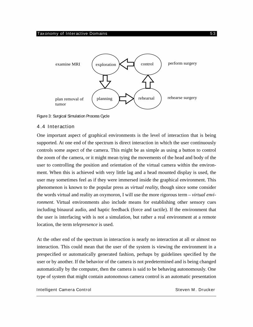
Taxonomy of Interactive Domains 53
Intelligent Camera Control Steven M. Drucker
Figure 3: Surgical Simulation Process Cycle
4.4 Interaction
One important aspect of graphical environments is the level of interaction that is being
supported. At one end of the spectrum is direct interaction in which the user continuously
controls some aspect of the camera. This might be as simple as using a button to control
the zoom of the camera, or it might mean tying the movements of the head and body of the
user to controlling the position and orientation of the virtual camera within the environ-
ment. When this is achieved with very little lag and a head mounted display is used, the
user may sometimes feel as if they were immersed inside the graphical environment. This
phenomenon is known to the popular press as
virtual reality
, though since some consider
the words virtual and reality an oxymoron, I will use the more rigorous term –
virtual envi-
ronment
. Virtual environments also include means for establishing other sensory cues
including binaural audio, and haptic feedback (force and tactile). If the environment that
the user is interfacing with is not a simulation, but rather a real environment at a remote
location, the term
telepresence
is used.
At the other end of the spectrum in interaction is nearly no interaction at all or almost no
interaction. This could mean that the user of the system is viewing the environment in a
prespecified or automatically generated fashion, perhaps by guidelines specified by the
user or by another. If the behavior of the camera is not predetermined and is being changed
automatically by the computer, then the camera is said to be behaving autonomously. One
type of system that might contain autonomous camera control is an automatic presentation
exploration
planning rehearsal
controlexamine MRI
plan removal of tumor
rehearse surgery
perform surgery
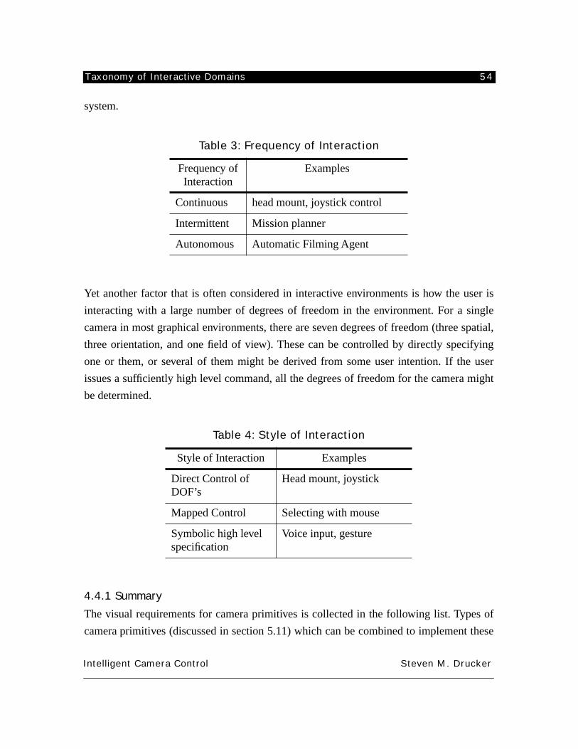
Taxonomy of Interactive Domains 54
Intelligent Camera Control Steven M. Drucker
system.
Yet another factor that is often considered in interactive environments is how the user is
interacting with a large number of degrees of freedom in the environment. For a single
camera in most graphical environments, there are seven degrees of freedom (three spatial,
three orientation, and one field of view). These can be controlled by directly specifying
one or them, or several of them might be derived from some user intention. If the user
issues a sufficiently high level command, all the degrees of freedom for the camera might
be determined.
4.4.1 Summary
The visual requirements for camera primitives is collected in the following list. Types of
camera primitives (discussed in section 5.11) which can be combined to implement these
Table 3: Frequency of Interaction
Frequency of Interaction
Examples
Continuous head mount, joystick control
Intermittent Mission planner
Autonomous Automatic Filming Agent
Table 4: Style of Interaction
Style of Interaction Examples
Direct Control of DOF’s
Head mount, joystick
Mapped Control Selecting with mouse
Symbolic high level specification
Voice input, gesture
Taxonomy of Interactive Domains 55
Intelligent Camera Control Steven M. Drucker
visual requirements are given in parenthesis and itemized in the subsequent list.
1. Always make sure that changes in the view make sense to the user (a,b,g).2. The user should, in general, recover information about his position within the
environment (f).3. The user should be able to recover the relative positions of different objects
within the environment, and the camera should be placed in positions wherethat information is presented (c).
4. Certain positions of the camera will allow completion of the task more con-veniently (a,b,c,e).
5. In many domains, there are restricted positions where the camera should nottravel, whether movement through walls is prevented, or restrictions to withina single room, or maintaining the visibility of certain objects (d).
6. For some domains, convenient movement through the environment is impor-tant. By convenient, I mean with little cognitive or computational effort onbehalf of the user (d).
7. Certain rules and conventions should be followed when presenting the infor-mation to external viewers (g)
8. Different styles of interaction must be supported, including continuous, inter-mittent, and autonomous (or supervisory) control. (h).
9. Different levels of control should be provided with access down to individualdegrees of freedom, on up to high level interpretations of commands. (h).
Briefly, those constraints in parenthesis (which will be discussed more extensively in sec-
tion 5.11) are as follows:
a) Direct constraints on one or more DOFs of the camera.b) Constraints on the derivatives of one or more DOFs of the camera.c) Constraints on the screenspace projection of one or more objects from a
camera.d) Constraints on movement through the environment.e) Constraints based on the visibility of an object within the environment.f) Constraints based on a view of another camera.g) Constraints based on stylistic and cinematic rules.h) The entire framework provides for the straightforward combination and
reusability of different constraints.
Taxonomy of Interactive Domains 56
Intelligent Camera Control Steven M. Drucker
4.5 Tasks demonstrated in this thesis
4.5.1 Virtual Museum
The Virtual Museum is a spatial database containing works of art, either sculptures or pic-
tures that are arranged in several rooms. It is an example of a task primarily in the
explor-
atory
domain. Various different levels of interaction are shown in the virtual museum
including direct control of the camera parameters, constrained movement based on a sin-
gle object, and nearly autonomous movement based on a guided tour calculation.
4.5.2 Mission Planner
As an example for the
rehearsal
domain, we show the mission planning system. This sys-
tem allows the user to experiment with different lines of sight in order to understand a plan
for flying a military mission. Again, various levels of control are shown. Simple, direct
interaction, constrained interaction in a very similar fashion to the football game, and
finally, limited autonomy.
4.5.3 Conversation
Filming a conversation via an autonomous agent is a simple demonstration of the ways in
which the primitives described in this thesis can be combined and formed into behaviors.
It is an example of task in the
planning
domain.
4.5.4 Virtual Football Game
Another
planning
task, with a somewhat different interface than the conversation is the
virtual football game. This environment differs significantly from the virtual museum in
that the museum was primarily a static environment that was large enough to require
exploration. The virtual football game is a dynamic environment where the user is trying
to watch the motion of several characters at once. In the virtual football game, we examine
direct control of the camera through several simple widgets. We examine limited auton-
omy in using the system as a director’s assistant. And finally we examine high level inter-
action in the form of the automatic generation of a sequence.
Taxonomy of Interactive Domains 57
Intelligent Camera Control Steven M. Drucker
4.5.5 Visibility assistant
Finally we look at a simple experiment in the control domain. The task in this example is
to perform some sort of manipulation on an object in the graphical environment. The visi-
bility assistant moves the viewpoint around occluding objects to make sure that the object
is always visible to the user.
Camera Primitives 58
Intelligent Camera Control Steven M. Drucker
CHAPTER 5. CAMERA PRIMITIVES
The following section addresses the central notion of camera control: that of camera prim-
itives. Camera primitives are selected based on task level goals in the different domains
discussed in the previous chapter. By specifying these goals in terms of constraints, the
primitives can be expressed in a domain independent manner allowing them to be com-
bined, reused, and sequenced as appropriate for the task at hand.
Camera primitives can be looked at both in terms of the task level goals they represent, and
the formal, mathematical machinery that is involved in their specification and satisfaction.
The first part of this chapter examines a variety of domains from which camera primitives
can be derived. In the second part of this chapter, I examine formally the mathematical
derivation of the constraint framework at the core of this thesis. I start with a discussion of
the view transformation since it is central to the way in which a virtual camera transforms
the environment into the image that the user sees, and then give specifications for con-
straints that can achieve the goals outlined in the first part. I also broadly classify the con-
straints into different types based on their mathematical structure.
This chapter does not discuss any interfaces for constructing or combining primitives. That
is discussed in chapter 6.
5.1 Procedural Representation
A slight digression is in order before a discussion of camera primitives as constraints can
take place. Initial attempts at specifying camera primitives began with the CINEMA sys-
tem [Drucker92]. In this system, camera commands were embedded in a procedural, inter-
preted language which had built in commands for mathematical functions, and database
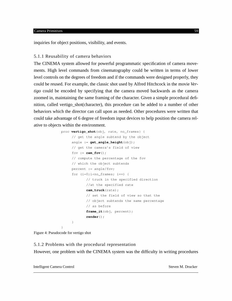
Camera Primitives 59
Intelligent Camera Control Steven M. Drucker
inquiries for object positions, visibility, and events.
5.1.1 Reusability of camera behaviors
The CINEMA system allowed for powerful programmatic specification of camera move-
ments. High level commands from cinematography could be written in terms of lower
level controls on the degrees of freedom and if the commands were designed properly, they
could be reused. For example, the classic shot used by Alfred Hitchcock in the movie
Ver-
tigo
could be encoded by specifying that the camera moved backwards as the camera
zoomed in, maintaining the same framing of the character. Given a simple procedural defi-
nition, called vertigo_shot(character), this procedure can be added to a number of other
behaviors which the director can call upon as needed. Other procedures were written that
could take advantage of 6 degree of freedom input devices to help position the camera rel-
ative to objects within the environment.
proc
vertigo_shot
(obj, rate, no_frames} {
// get the angle subtend by the object
angle :=
get_angle_height
(obj);
// get the camera’s field of view
fov :=
cam_fov
();
// compute the percentage of the fov
// which the object subtends
percent := angle/fov;
for (i=0;i<no_frames; i++) {
// truck in the specified direction
//at the specified rate
cam_truck
(rate);
// set the field of view so that the
// object subtends the same percentage
// as before
frame_it
(obj, percent);
render
();
}
}
Figure 4: Pseudocode for vertigo shot
5.1.2 Problems with the procedural representation
However, one problem with the CINEMA system was the difficulty in writing procedures
Camera Primitives 60
Intelligent Camera Control Steven M. Drucker
in a way that they could be combined with other procedures. This was a significant draw-
back since the entire purpose of the system was to provide the user with tools for simply
achieving desired camera movements and if the user needed to rewrite a special purpose
procedure each time a new movement was needed then the user had to be a skilled pro-
grammer in addition to a cinematic director. Related to this problem, was that it was diffi-
cult to write single procedures that were general enough. More often than not, constants
needed to be used in a procedure that were only appropriate for a certain character and
when applied to another character the procedure had to be rewritten. A wide enough base
of initial procedures did make it possible for convenient rewrites for new procedures, but
still, programming was required to use the system.
The successes and the problems of the CINEMA system led to the idea of controlling the
camera on the basis of constraint satisfaction. Constraints are essentially an encapsulation
of a user’s intentions. They can be combined and generalized more conveniently than pro-
cedural programming, and have desirable behavior even if all the constraints can’t be satis-
fied at the same time. The following section will describe how useful constraints were
derived from a variety of disciplines.
5.2 Deriving Primitives as Constraints
Camera primitives can be derived from a number of disciplines. These disciplines tend to
be distinct from the domains discussed in chapter 4 because they do not necessarily require
a computer graphical environment but rather involve communication of visual concepts or
useful algorithmic techniques from related fields. Some of the disciplines from which to
derive camera primitives are as follows:
• Cinematography
There are a wealth of conventions, rules, and suggestions for the placement of cameras for
filming various situations. These include framing conventions; editing rules; continuity
rules, etc. By formalizing the widely circumstantial body of literature these conventions
can be used in other domains. In general I call the types of primitives derived from cine-
matography
projective
constraints since they involve projecting objects from world space
Camera Primitives 61
Intelligent Camera Control Steven M. Drucker
into a framed screen space. These projective constraints are extremely useful since they
find the position and orientation of the camera based on the desired position of objects
within the frame. Only two works in the computer graphics literature touch upon finding
camera parameters based on the screen space projections of objects. The first of these is
Blinn’s formulations [Blinn88] for creating planet fly-bys which are discussed in section
5.8.2. Blinn’s work is far less general and is primarily suited to the specific task of a fore-
ground and background object on the screen. The second work is by Gleicher and Witkin
[Gleicher92] discussed in section 5.11.3. This work does not find camera parameters, but
allows the system to update the camera based on screen space projections of objects once a
desired set of camera parameters has already been found. The work presented in this thesis
on projection constraints is general purpose and useful for finding camera parameters as
opposed to just maintaining them.
• Task performance concerns
Naturally, task performance is extremely situation dependent. In general, the ones I mean
in this category tend to be concerned with letting the user maintain the visibility of certain
items of interest; or letting the viewer maintain context based on the orientation of oneself
and the position of an object of interest in relation to other objects within the environ-
ment.These are constraints that let the user achieve a certain task which is often separate
from controlling the camera itself. In general, the primitives derived from this category are
visibility
constraints, and constraints on the maximum change of any of the camera param-
eters.
• Physical limitations for cameras
These constraints are based on dynamic simulation for the camera and camera-related
machinery (dollies, cranes, arms, etc.). If one considers these, the system could be made
appropriate for preplanning the filming of actual situations or controlling real life robotic
cameras. These constraints also include issues such as collision detection between the
camera and objects in environment and collision-free
path planning
through the environ-
ment.
Camera Primitives 62
Intelligent Camera Control Steven M. Drucker
• Human Factors
There are certain basic limits for the human system to be able to comprehend input from
the visual system. These limits tend to define preferred numbers of frames per second for
the graphical environment and maximum angular movement rates for the camera. Many
human factors problems in visual displays are due to equipment limitations, such as the
limited field of view of many head mounted displays (HMD) or slow tracking of head
movements in HMDs. However, care can be taken to constrain motions of the camera
within the graphical environment so as not to produce images which violate some basic
human factors measurements. The basic constraints derived from this domain are limits on
the maximum changes of any of the camera parameters, and agreement between motions
of the head and changes in the visual displays.
• Interface Design Principles
Since the framework that is described in this thesis is meant to serve as the underlying
mechanism on top of which a variety of different interfaces is placed, special effort is
made to make sure that effective interfaces can be built on top of the framework. However,
in depth user interface design/testing/verification will not be performed. (See chapter 7 for
a more thorough evaluation of the interfaces.)
5.3 Cinematic Constraints
One of the easiest sources of cinematic constraints are from a number of books intended
for beginning practitioners in the field of film-making. This thesis uses several of those
books as a reference for constructing cinematic primitives, notably
Grammar of the Edit
,
Grammar of the Film Language
, and
Shot by Shot
[Arijon76, Katz88, Katz92].
Roy Thompson [Thompson94] proposes a simple categorization of camera shots based on
four elements which either may or may not change during the duration of the shot. These
elements are the lens (zooming), the camera (panning, tilting, rolling), the mounting,
(trucking, dollying, craning), and the subject. In his basic framework there are three types
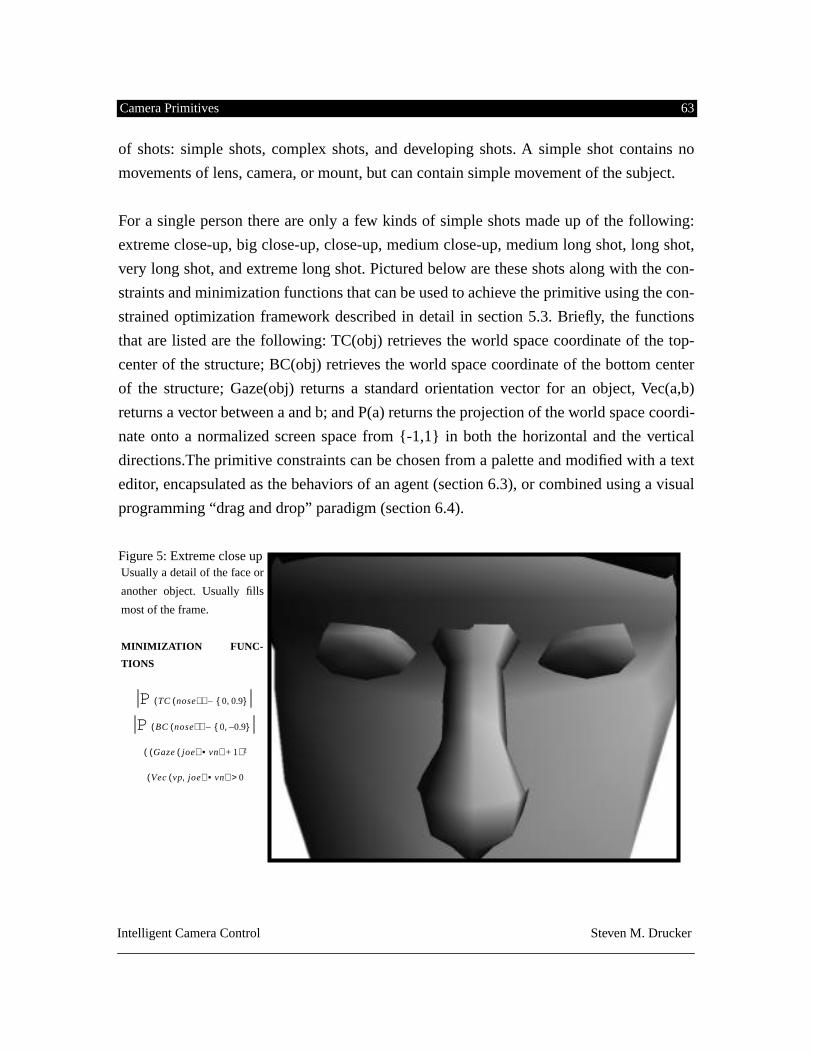
Camera Primitives 63
Intelligent Camera Control Steven M. Drucker
of shots: simple shots, complex shots, and developing shots. A simple shot contains no
movements of lens, camera, or mount, but can contain simple movement of the subject.
For a single person there are only a few kinds of simple shots made up of the following:
extreme close-up, big close-up, close-up, medium close-up, medium long shot, long shot,
very long shot, and extreme long shot. Pictured below are these shots along with the con-
straints and minimization functions that can be used to achieve the primitive using the con-
strained optimization framework described in detail in section 5.3. Briefly, the functions
that are listed are the following: TC(obj) retrieves the world space coordinate of the top-
center of the structure; BC(obj) retrieves the world space coordinate of the bottom center
of the structure; Gaze(obj) returns a standard orientation vector for an object, Vec(a,b)
returns a vector between a and b; and P(a) returns the projection of the world space coordi-
nate onto a normalized screen space from {-1,1} in both the horizontal and the vertical
directions.The primitive constraints can be chosen from a palette and modified with a text
editor, encapsulated as the behaviors of an agent (section 6.3), or combined using a visual
programming “drag and drop” paradigm (section 6.4).
Figure 5: Extreme close up
Usually a detail of the face or
another object. Usually fills
most of the frame.
MINIMIZATION FUNC-
TIONS
P TC nose
( )( ) 0 0.9,{ }–
P BC nose( )( ) 0 0.9–,{ }–
Gaze joe( ) vn•( ) 1+( ) 2
Vec vp joe,( ) vn•( ) 0>
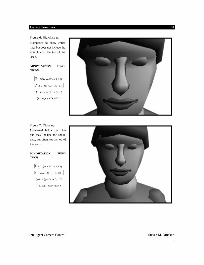
Camera Primitives 64
Intelligent Camera Control Steven M. Drucker
Figure 6: Big close up
Figure 7: Close up
Composed to show entire
face but does not include the
chin line or the top of the
head.
MINIMIZATION FUNC-
TIONS
P TC nose( )( ) 0 0.3,{ }–
P BC nose( )( ) 0 1.1–,{ }–
Gaze joe( ) vn•( ) 1+( ) 2
Vec vp joe,( ) vn•( ) 0>
Composed below the chin
and may include the shoul-
ders, but often not the top of
the head.
MINIMIZATION FUNC-
TIONS
P TC head( )( ) 0 1.2,{ }–
P BC neck( )( ) 0 0.8–,{ }–
Gaze joe( ) vn•( ) 1+( ) 2
Vec vp joe,( ) vn•( ) 0>
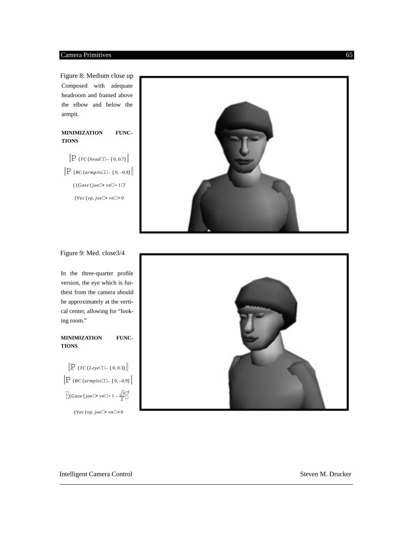
Camera Primitives 65
Intelligent Camera Control Steven M. Drucker
Figure 8: Medium close up
Figure 9: Med. close3/4
Composed with adequate
headroom and framed above
the elbow and below the
armpit.
MINIMIZATION FUNC-
TIONS
P TC head( )( ) 0 0.7,{ }–
P BC armpits( )( ) 0 0.9–,{ }–
Gaze joe( ) vn•( ) 1+( ) 2
Vec vp joe,( ) vn•( ) 0>
In the three-quarter profile
version, the eye which is fur-
thest from the camera should
be approximately at the verti-
cal center, allowing for “look-
ing room.”
MINIMIZATION FUNC-
TIONS
P TC Leye( )( ) 0 0.3,{ }–
P BC armpits( )( ) 0 0.9–,{ }–
Gaze joe( ) vn•( ) 1 32
-------–+ 2
Vec vp joe,( ) vn•( ) 0>
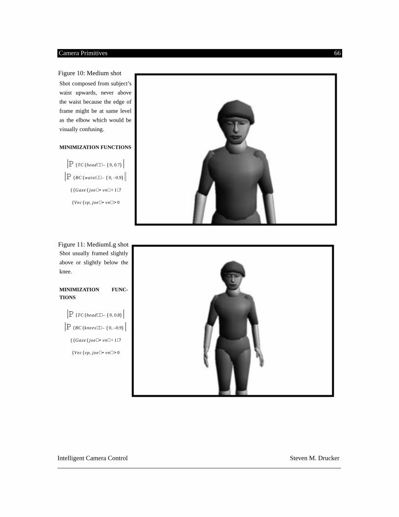
Camera Primitives 66
Intelligent Camera Control Steven M. Drucker
Figure 10: Medium shot
Figure 11: MediumLg shot
Shot composed from subject’s
waist upwards, never above
the waist because the edge of
frame might be at same level
as the elbow which would be
visually confusing.
MINIMIZATION FUNCTIONS
P TC head( )( ) 0 0.7,{ }–
P BC waist( )( ) 0 0.9–,{ }–
Gaze joe( ) vn•( ) 1+( ) 2
Vec vp joe,( ) vn•( ) 0>
Shot usually framed slightly
above or slightly below the
knee.
MINIMIZATION FUNC-
TIONS
P TC head( )( ) 0 0.8,{ }–
P BC knees( )( ) 0 0.9–,{ }–
Gaze joe( ) vn•( ) 1+( ) 2
Vec vp joe,( ) vn•( ) 0>
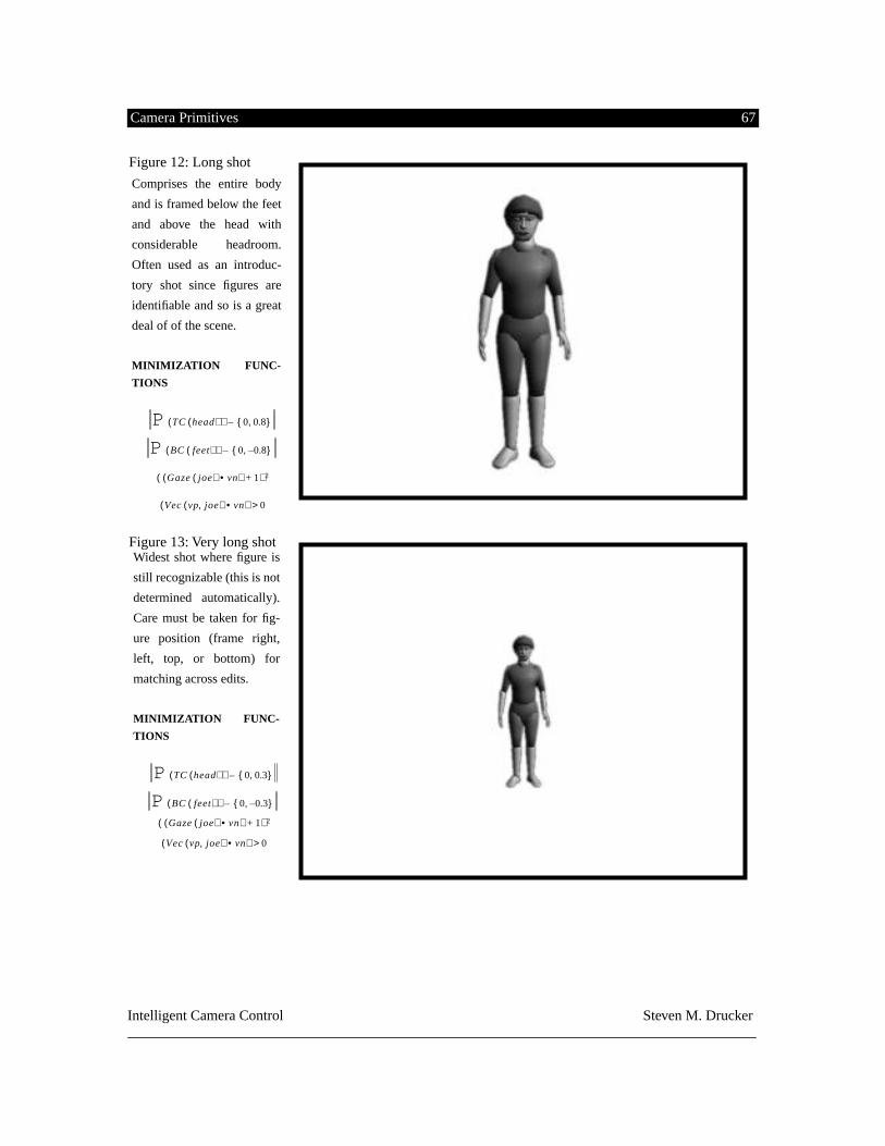
Camera Primitives 67
Intelligent Camera Control Steven M. Drucker
Figure 12: Long shot
Figure 13: Very long shot
Comprises the entire body
and is framed below the feet
and above the head with
considerable headroom.
Often used as an introduc-
tory shot since figures are
identifiable and so is a great
deal of of the scene.
MINIMIZATION FUNC-
TIONS
P TC head( )( ) 0 0.8,{ }–
P BC feet( )( ) 0 0.8–,{ }–
Gaze joe( ) vn•( ) 1+( ) 2
Vec vp joe,( ) vn•( ) 0>
Widest shot where figure is
still recognizable (this is not
determined automatically).
Care must be taken for fig-
ure position (frame right,
left, top, or bottom) for
matching across edits.
MINIMIZATION FUNC-
TIONS
P TC head( )( ) 0 0.3,{ }–
P BC feet( )( ) 0 0.3–,{ }–
Gaze joe( ) vn•( ) 1+( ) 2
Vec vp joe,( ) vn•( ) 0>
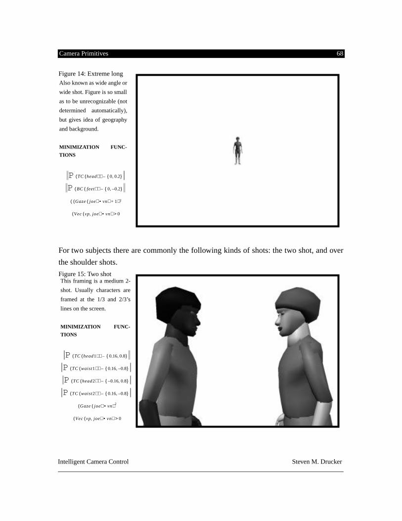
Camera Primitives 68
Intelligent Camera Control Steven M. Drucker
Figure 14: Extreme long
For two subjects there are commonly the following kinds of shots: the two shot, and over
the shoulder shots.
Figure 15: Two shot
Also known as wide angle or
wide shot. Figure is so small
as to be unrecognizable (not
determined automatically),
but gives idea of geography
and background.
MINIMIZATION FUNC-
TIONS
P TC head( )( ) 0 0.2,{ }–
P BC feet( )( ) 0 0.2–,{ }–
Gaze joe( ) vn•( ) 1+( ) 2
Vec vp joe,( ) vn•( ) 0>
This framing is a medium 2-
shot. Usually characters are
framed at the 1/3 and 2/3’s
lines on the screen.
MINIMIZATION FUNC-
TIONS
P TC head1( )( ) 0.16 0.8,{ }–
P TC waist1( )( ) 0.16 0.8–,{ }–
P TC head2( )( ) 0.16– 0.8,{ }–
P TC waist2( )( ) 0.16 0.8–,{ }–
Gaze joe( ) vn•( ) 2
Vec vp joe,( ) vn•( ) 0>
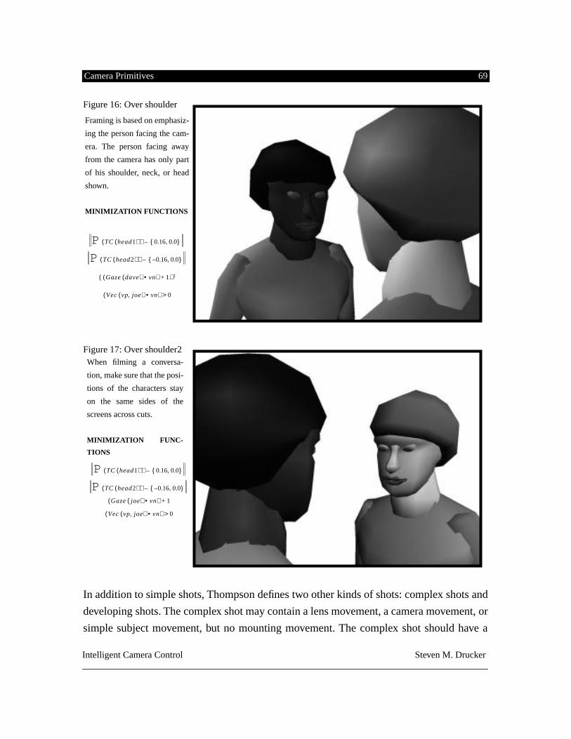
Camera Primitives 69
Intelligent Camera Control Steven M. Drucker
Figure 16: Over shoulder
Figure 17: Over shoulder2
In addition to simple shots, Thompson defines two other kinds of shots: complex shots and
developing shots. The complex shot may contain a lens movement, a camera movement, or
simple subject movement, but no mounting movement. The complex shot should have a
Framing is based on emphasiz-
ing the person facing the cam-
era. The person facing away
from the camera has only part
of his shoulder, neck, or head
shown.
MINIMIZATION FUNCTIONS
P TC head1( )( ) 0.16 0.0,{ }–
P TC head2( )( ) 0.16– 0.0,{ }–
Gaze dave( ) vn•( ) 1+( ) 2
Vec vp joe,( ) vn•( ) 0>
When filming a conversa-
tion, make sure that the posi-
tions of the characters stay
on the same sides of the
screens across cuts.
MINIMIZATION FUNC-
TIONS
P TC head1( )( ) 0.16 0.0,{ }–
P TC head2( )( ) 0.16– 0.0,{ }
–
Gaze joe( ) vn•( ) 1+
Vec vp joe,( ) vn•( ) 0>
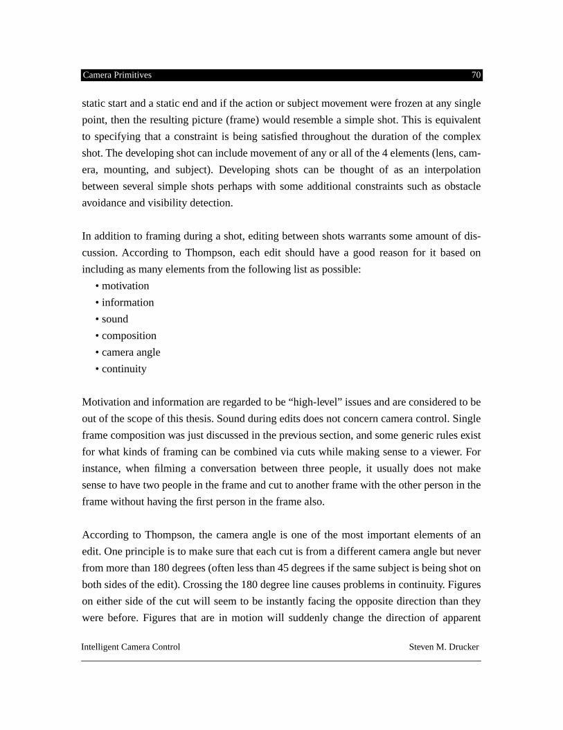
Camera Primitives 70
Intelligent Camera Control Steven M. Drucker
static start and a static end and if the action or subject movement were frozen at any single
point, then the resulting picture (frame) would resemble a simple shot. This is equivalent
to specifying that a constraint is being satisfied throughout the duration of the complex
shot. The developing shot can include movement of any or all of the 4 elements (lens, cam-
era, mounting, and subject). Developing shots can be thought of as an interpolation
between several simple shots perhaps with some additional constraints such as obstacle
avoidance and visibility detection.
In addition to framing during a shot, editing between shots warrants some amount of dis-
cussion. According to Thompson, each edit should have a good reason for it based on
including as many elements from the following list as possible:
• motivation
• information
• sound
• composition
• camera angle
• continuity
Motivation and information are regarded to be “high-level” issues and are considered to be
out of the scope of this thesis. Sound during edits does not concern camera control. Single
frame composition was just discussed in the previous section, and some generic rules exist
for what kinds of framing can be combined via cuts while making sense to a viewer. For
instance, when filming a conversation between three people, it usually does not make
sense to have two people in the frame and cut to another frame with the other person in the
frame without having the first person in the frame also.
According to Thompson, the camera angle is one of the most important elements of an
edit. One principle is to make sure that each cut is from a different camera angle but never
from more than 180 degrees (often less than 45 degrees if the same subject is being shot on
both sides of the edit). Crossing the 180 degree line causes problems in continuity. Figures
on either side of the cut will seem to be instantly facing the opposite direction than they
were before. Figures that are in motion will suddenly change the direction of apparent
Camera Primitives 71
Intelligent Camera Control Steven M. Drucker
motion. Constraints can be used to require the projection of vectors of gaze or of motion to
be approximately matched from cut to cut.
5.4 Task completion constraints
The constraints described in this section deal with positioning the camera in order to aid in
task completion for object identification or manipulation. The constraints have been
derived from a number of fields of study including earlier work in computer graphics, tele-
operation and robotics. The primary examples are visibility constraints, alignment of
manipulator control axes with the visual display, and positioning the camera based on the
best view in order to identify an object.
5.4.1 Object Visibility
Several strategies can be devised to maintain the visibility of an object.The algorithms
developed for this thesis are compatible with the constrained optimization framework
allowing object visibility constraints to be combined with other constraints such as path
planning and projection constraints. This work is in part based on the strategies suggested
by [Philips92; Seligman91; Karp90].
5.4.2 Object manipulability
When manipulating objects with 2D manipulators, certain views are often better then oth-
ers. For instance, there is often no way of conveniently mapping the motion of a user’s
mouse presses on the screen with a translation of the object in the same direction as the
viewing normal. Also if motions of a manipulator move an object in a different direction
than the corresponding one depicted on the screen, users often can not perform tasks well.
These are constraints suggested by [Philips92] and [McCormick91].
5.5 Object appearance
A number of constraints can be formulated in terms of finding an ideal view for a particu-
lar object. This view usually implies that the object’s projection must fill a certain amount
of the viewport (a projective constraint). It also implies that the projection should provide
as much geometric information as possible about the object [Kamada88]. One way to do
Camera Primitives 72
Intelligent Camera Control Steven M. Drucker
this is to take the basic visibility constraints and maximize the visibility of a number of
preselected faces of an object. Attempts should also be made to minimize distortions of
extreme linear projections ( the field of view should not become too large).
5.6 Physical Limitations
In general, physical limitations come about from trying to simulate the motions of a real
camera. One reason to do so, is to design a system to help previsualize the filming of a
movie. By providing the proper physical restrictions on a simulated camera, the system
can help design an appropriate environment for filming a scene. It can also help highlight
difficulties or timing issues during filming. Furthermore, complicated shots can be planned
and practiced before the expensive filming process.
Physical constraints also serve to help place natural constraints on camera movements. In
the real world, a camera can not pass through objects, which can easily occur in a graphi-
cal environment, which is often extremely disorienting. Different kinds of mountings pro-
duce different stylistic effects, such as a natural easing in and out of a motion with a fluid
head.
The constraints derived from the physical domain and demonstrated in this thesis are colli-
sion constraints; pathplanning constraints (where the camera can generate a collision free
path from one point in an environment to another); and velocity constraints on changes in
any of the degrees of freedom of the camera. These are described in more detail in sections
5.11.4 and 5.11.5.
5.7 Human Factors
Hochberg and Brooks [Hochberg86, Hochberg87] discuss a number of issues in the human
perception of motion pictures. Those issues with the most direct bearing on the derivation
of camera primitives are the ability of observers to comprehend changes in camera posi-
tion across temporal sequences of film. One mechanism suggests that if the rate of change
of any of the camera parameters from frame to frame is too large, then the observer may
have difficulties if care is not taken to supply perceptual clues to the other potential mech-
Camera Primitives 73
Intelligent Camera Control Steven M. Drucker
anisms. This suggests that at least one important camera primitive is the ability to specify a
maximum rate of change for any of the camera parameters. What that rate of change
should be however, is extremely dependent on the update rate of frames and the content of
the image. Another mechanism might be the ability of the observer to construct a transfor-
mation that relates objects in one image to objects in subsequent images. This construction
of this transformation may be related to research by Shephard on mental rotation of objects
[Shepard71]. To construct such a transformation though requires readily and uniquely
identifiable objects in the image. Instead of producing a restriction on camera control, this
mechanism might suggest a restriction on the content of the graphical environment. This
restriction may also be the basis for an architectural design technique called wayfinding
[Lynch60], where landmarks are placed in particular places to help keep people oriented.
The final mechanism posits the existance of some sort of cognitive map which may be
built up by the ability to locate and place familiar landmarks in a map in relation to each
other. It is still a debatable issue of whether cognitive maps are represented internally as
spatial maps or as symbolic maps. Evidence exists to support both hypotheses. This mech-
anism argues for a camera primitive that can be considered a meta-primitive. The user
should be able to quickly and conveniently track the position of the camera from some
external, map-like view. Many of the applications demonstrated in this thesis support this
style of interaction. The definition of a constraint to limit the speed of motion of a camera
is discussed in section 5.11.5 and that constraint is used in 6.2.
5.8 The Viewing Transformation
The following section presents the basic mathematical techniques which underlie the con-
straint framework.
5.8.1 Derivation of the standard Viewing Transformation
The fundamental operation of a virtual camera is to transform objects from a perspective
view in the world space of a graphical environment into a device’s display space. The fol-
lowing section describes the mathematical operations that occur to convert points from the
world space in which they are originally represented, into a coordinate system that can be
displayed on the screen. Much of this transformation can occur in the hardware of graphics
workstations so it can be performed very quickly. Many of the constraints described in the
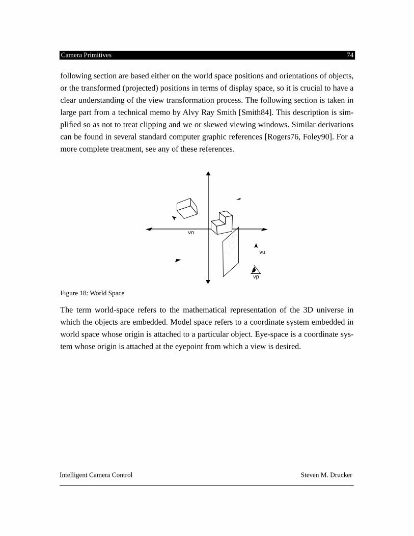
Camera Primitives 74
Intelligent Camera Control Steven M. Drucker
following section are based either on the world space positions and orientations of objects,
or the transformed (projected) positions in terms of display space, so it is crucial to have a
clear understanding of the view transformation process. The following section is taken in
large part from a technical memo by Alvy Ray Smith [Smith84]. This description is sim-
plified so as not to treat clipping and we or skewed viewing windows. Similar derivations
can be found in several standard computer graphic references [Rogers76, Foley90]. For a
more complete treatment, see any of these references.
Figure 18: World Space
The term world-space refers to the mathematical representation of the 3D universe in
which the objects are embedded. Model space refers to a coordinate system embedded in
world space whose origin is attached to a particular object. Eye-space is a coordinate sys-
tem whose origin is attached at the eyepoint from which a view is desired.
vp
vn
vu
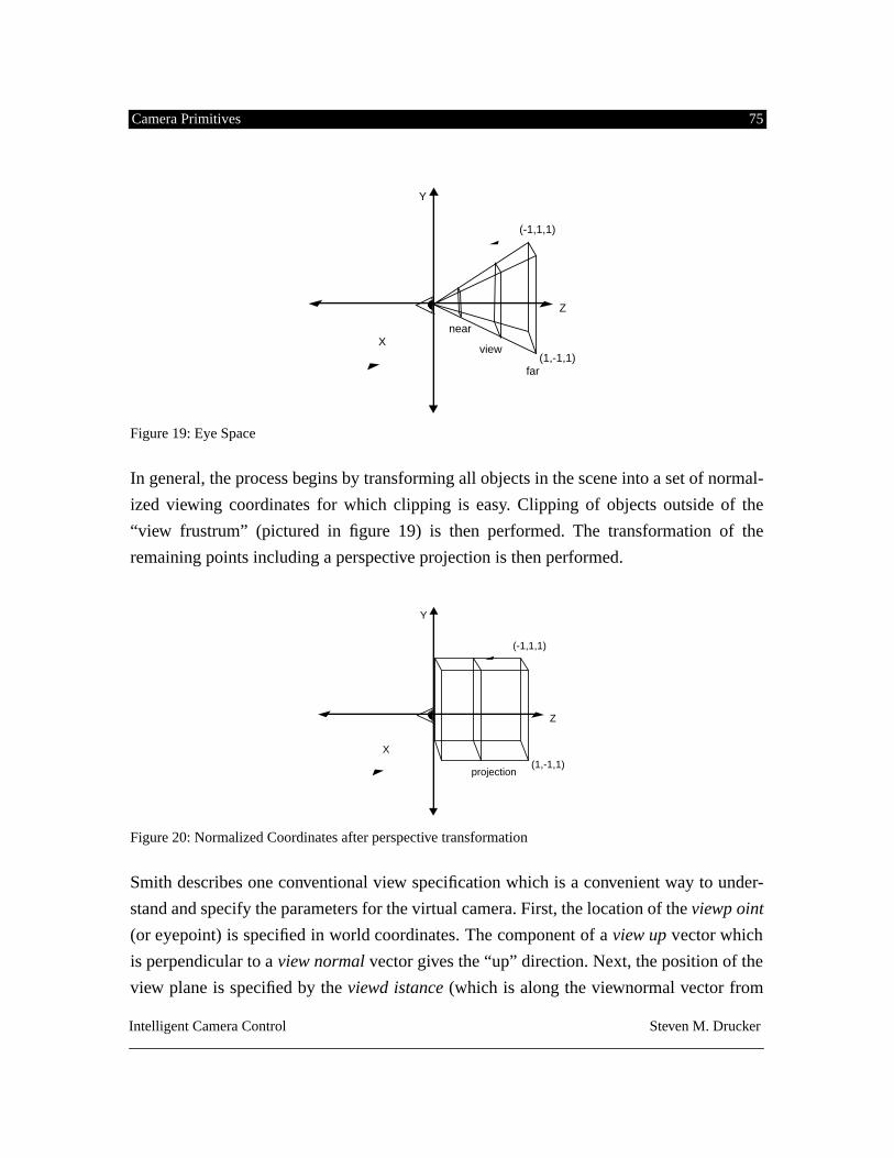
Camera Primitives 75
Intelligent Camera Control Steven M. Drucker
Figure 19: Eye Space
In general, the process begins by transforming all objects in the scene into a set of normal-
ized viewing coordinates for which clipping is easy. Clipping of objects outside of the
“view frustrum” (pictured in figure 19) is then performed. The transformation of the
remaining points including a perspective projection is then performed.
Figure 20: Normalized Coordinates after perspective transformation
Smith describes one conventional view specification which is a convenient way to under-
stand and specify the parameters for the virtual camera. First, the location of the
viewp oint
(or eyepoint) is specified in world coordinates. The component of a
view up
vector which
is perpendicular to a
view normal
vector gives the “up” direction. Next, the position of the
view plane is specified by the
viewd istance
(which is along the viewnormal vector from
view
far
near
(-1,1,1)
(1,-1,1)
Y
Z
X
projection
(-1,1,1)
(1,-1,1)
Y
Z
X
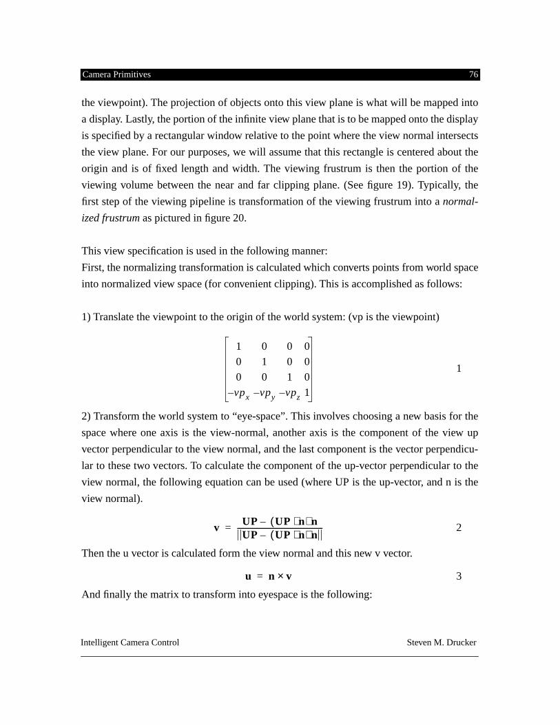
Camera Primitives 76
Intelligent Camera Control Steven M. Drucker
the viewpoint). The projection of objects onto this view plane is what will be mapped into
a display. Lastly, the portion of the infinite view plane that is to be mapped onto the display
is specified by a rectangular window relative to the point where the view normal intersects
the view plane. For our purposes, we will assume that this rectangle is centered about the
origin and is of fixed length and width. The viewing frustrum is then the portion of the
viewing volume between the near and far clipping plane. (See figure 19). Typically, the
first step of the viewing pipeline is transformation of the viewing frustrum into a
normal-
ized frustrum
as pictured in figure 20.
This view specification is used in the following manner:
First, the normalizing transformation is calculated which converts points from world space
into normalized view space (for convenient clipping). This is accomplished as follows:
1) Translate the viewpoint to the origin of the world system: (vp is the viewpoint)
1
2) Transform the world system to “eye-space”. This involves choosing a new basis for the
space where one axis is the view-normal, another axis is the component of the view up
vector perpendicular to the view normal, and the last component is the vector perpendicu-
lar to these two vectors. To calculate the component of the up-vector perpendicular to the
view normal, the following equation can be used (where UP is the up-vector, and n is the
view normal).
2
Then the u vector is calculated form the view normal and this new v vector.
3
And finally the matrix to transform into eyespace is the following:
1 0 0 0
0 1 0 0
0 0 1 0
vpx– vpy– vpz– 1
v UP UP n
⋅( )
n
–UP UP n⋅( ) n–
-----------------------------------------------=
u n v
×
=
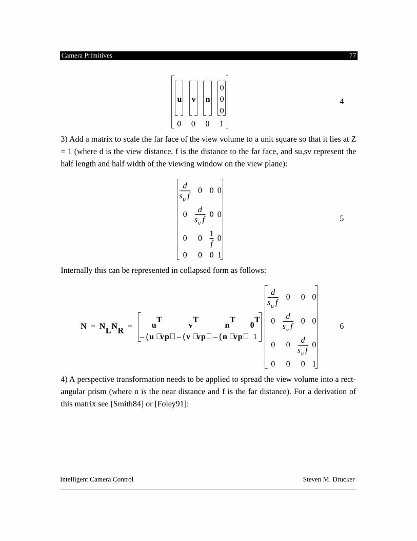
Camera Primitives 77
Intelligent Camera Control Steven M. Drucker
4
3) Add a matrix to scale the far face of the view volume to a unit square so that it lies at Z
= 1 (where d is the view distance, f is the distance to the far face, and su,sv represent the
half length and half width of the viewing window on the view plane):
5
Internally this can be represented in collapsed form as follows:
6
4) A perspective transformation needs to be applied to spread the view volume into a rect-
angular prism (where n is the near distance and f is the far distance). For a derivation of
this matrix see [Smith84] or [Foley91]:
u v n0
0
0
0 0 0 1
dsu f-------- 0 0 0
0d
sv f-------- 0 0
0 01f--- 0
0 0 0 1
N NLNRu
Tv
Tn
T0
T
u vp
⋅( )– v vp⋅( )– n vp⋅( )– 1
dsu f-------- 0 0 0
0d
sv f-------- 0 0
0 0d
sv f-------- 0
0 0 0 1
= =
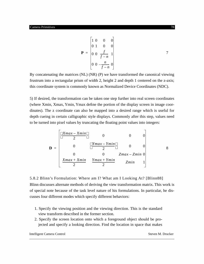
Camera Primitives 78
Intelligent Camera Control Steven M. Drucker
7
By concatenating the matrices (NL) (NR) (P) we have transformed the canonical viewing
frustrum into a rectangular prism of width 2, height 2 and depth 1 centered on the z-axis;
this coordinate system is commonly known as Normalized Device Coordinates (NDC).
5) If desired, the transformation can be taken one step further into real screen coordinates
(where Xmin, Xmax, Ymin, Ymax define the portion of the display screen in image coor-
dinates). The z coordinate can also be mapped into a desired range which is useful for
depth cueing in certain calligraphic style displays. Commonly after this step, values need
to be turned into pixel values by truncating the floating point values into integers:
8
5.8.2 Blinn’s Formulation: Where am I? What am I Looking At? [Blinn88]
Blinn discusses alternate methods of deriving the view transformation matrix. This work is
of special note because of the task level nature of his formulations. In particular, he dis-
cusses four different modes which specify different behaviors:
1. Specify the viewing position and the viewing direction. This is the standardview transform described in the former section.
2. Specify the screen location onto which a foreground object should be pro-jected and specify a looking direction. Find the location in space that makes
P
1 0 0 0
0 1 0 0
0 0f
f n–------------ 1
0 0 nf n–------------– 0
=
D
Xmax Xmin–2
----------------------------------- 0 0 0
0Ymax Ymin–
2---------------------------------
0 0
0 0 Zmax Zmin– 0
Xmax Xmin+2
----------------------------------- Ymax Ymin+2
---------------------------------- Zmin 1
=
Camera Primitives 79
Intelligent Camera Control Steven M. Drucker
this situation true.3. Specify the location and space and a screen location for a background object
to be projected onto. Find the view direction that makes this situation true.4. Specify the screen location of a foreground location and specify the screen
location of a background object and calculate both the viewing position andthe viewing direction that makes the situation true.
Blinn provides an algebraic derivation for each of the modes and discusses how to interpo-
late between the results of different mode specifications in order to create continuous cam-
era movements. His formulation is useful, but relatively simplistic. In each of the modes,
the field of view may not be altered in order to achieve the desired situation. Each mode
must be special cased (there is a different procedure to use to calculate the necessary vec-
tors for each mode). There is no way to find the “best” solution if certain conditions can
not be achieved, or to be able to lock some of the camera parameters to a certain value.
Blinn’s formulations lead naturally to a scheme based on constrained optimization, where
each mode is essentially specifying different constraints that must be satisfied. By refor-
mulating the problem in terms of constrained optimization, the solution process is easier
and has the advantages of addressing all of these problems. There are however some disad-
vantages to an optimization approach which are discussed in section 5.10.
5.9 Object and Camera State Functions
In the following section, let
q
represent the camera parameters where the 7 mem-
bers of
q
are defined as follows (x,y,z, azimuth, pitch, roll, fov). Fov is defined between 0
and 180 degrees exclusively.
We can easily define a number of functions based on some object O. or some camera state
vector q. Some example functions are listed in tables 5 and 6. After a description of some
constrained optimization techniques, we will derive some basic camera primitives in terms
q
ℜ
7
∈
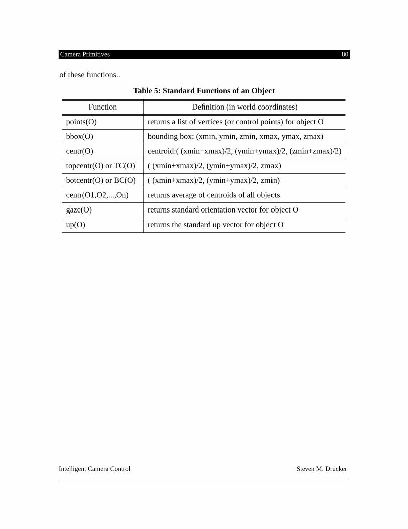
Camera Primitives 80
Intelligent Camera Control Steven M. Drucker
of these functions..
Table 5: Standard Functions of an Object
Function Definition (in world coordinates)
points(O) returns a list of vertices (or control points) for object O
bbox(O) bounding box: (xmin, ymin, zmin, xmax, ymax, zmax)
centr(O) centroid:( (xmin+xmax)/2, (ymin+ymax)/2, (zmin+zmax)/2)
topcentr(O) or TC(O) ( (xmin+xmax)/2, (ymin+ymax)/2, zmax)
botcentr(O) or BC(O) ( (xmin+xmax)/2, (ymin+ymax)/2, zmin)
centr(O1,O2,...,On) returns average of centroids of all objects
gaze(O) returns standard orientation vector for object O
up(O) returns the standard up vector for object O
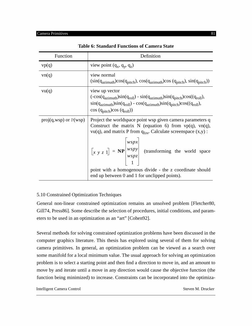
Camera Primitives 81
Intelligent Camera Control Steven M. Drucker
5.10 Constrained Optimization Techniques
General non-linear constrained optimization remains an unsolved problem [Fletcher80,
Gill74, Press86]. Some describe the selection of procedures, initial conditions, and param-
eters to be used in an optimization as an “art” [Cohen92].
Several methods for solving constrained optimization problems have been discussed in the
computer graphics literature. This thesis has explored using several of them for solving
camera primitives. In general, an optimization problem can be viewed as a search over
some manifold for a local minimum value. The usual approach for solving an optimization
problem is to select a starting point and then find a direction to move in, and an amount to
move by and iterate until a move in any direction would cause the objective function (the
function being minimized) to increase. Constraints can be incorporated into the optimiza-
Table 6: Standard Functions of Camera State
Function Definition
vp(q) view point (q
x
, q
y
, q
z
)
vn(q) view normal (sin(q
azimuth
)cos(q
pitch
), cos(q
azimuth
)cos (q
pitch
), sin(q
pitch
))
vu(q) view up vector(-cos(q
azimuth
)sin(q
roll
) - sin(q
azimuth
)sin(q
pitch
)cos((q
roll
), sin(q
azimuth
)sin(q
roll
) - cos(q
azimuth
)sin(q
pitch
)cos((q
roll
),cos (q
pitch
)cos (q
roll
))
proj(q,wsp) or
P
(wsp) Project the worldspace point wsp given camera parameters qConstruct the matrix N (equation 6) from vp(q), vn(q),vu(q), and matrix P from q
fov
. Calculate screenspace (x,y) :
(transforming the world space
point with a homogenous divide - the z coordinate shouldend up between 0 and 1 for unclipped points).
x y z 1 NP
wspx
wspy
wspz
1
=
Camera Primitives 82
Intelligent Camera Control Steven M. Drucker
tion problem in several different ways. One way is to express the constraints as penalty
functions and add them to the original objective to create a new unconstrained objective
function to be solved. If there is no optimization to be performed, satisfying the constraints
themselves becomes the optimization problem. By expressing only a certain kind of objec-
tive functions as energy values and the constraints can as forces. The search for a local
minimum effectively becomes a forward simulation of a physical system can be used to
bring the system to a minimum energy value subject to constraints. This is the technique
used by [Barzel88, Pentland90].
Another method, which is particularly useful when the system is already at or near the
minimum and the desire is to maintain certain constraints, is to solve a system in equations
in terms of the derivatives of the parameters to be solved and find the velocities which
force the state to stay in the Null-space of the solution, that is, to make sure that the con-
straints are always satisfied. This has the advantage of being a linear system in the deriva-
tives of the camera parameters and can be solved efficiently. This is essentially the method
used for the so-called through-the-lens camera control discussed in section 5.11.3.
Yet another technique is based on the idea that the gradient of the object function must be
equal to some linear combination of the constraint gradiants for the solution to represent a
constrained minimum. This leads to the use of Lagrange multipliers which multiply the
constraints and add the resultant function to the objective function. Again, this turns the
constrained problem into an unconstrained problem in the resulting objecting function.
The Langrange multipliers correspond roughly to influences of the constraints on the
objective function.
5.10.1 Sequential Quadratic Programming
The method used in this thesis is based on the technique of sequential quadratic program-
ming.The following section is based in part on the extremely clear discussion presented in
[Cohen92]. By combining Lagrange’s methods with a Newton style search for a solution,
the problem can be formulated as a sequence of quadratic subproblems that lead to a solu-
tion of the constrained problem. The gradient of the Lagrangian at a local optimum
must be equal to 0.S* λ
*,( )
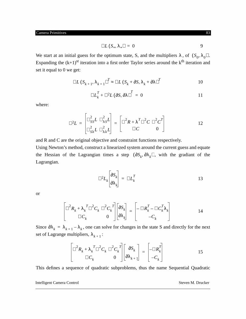
Camera Primitives 83
Intelligent Camera Control Steven M. Drucker
9
We start at an initial guess for the optimum state, S, and the multipliers , of .
Expanding the (k+1)
st
iteration into a first order Taylor series around the k
th
iteration and
set it equal to 0 we get:
10
11
where:
12
and R and C are the original objective and constraint functions respectively.
Using Newton’s method, construct a linearized system around the current guess and equate
the Hessian of the Lagrangian times a step , with the gradiant of the
Lagrangian.
13
or
14
Since , one can solve for changes in the state S and directly for the next
set of Lagrange multipliers, :
15
This defines a sequence of quadratic subproblems, thus the name Sequential Quadratic
L S* λ
*,( )∇
0=
λ S0 λ
0,( )
L Sk 1+ λk 1+,( )∇
TL Sk S∂+ λk λ∂+,( )∇ T
≈
LkT
L S∂ λ∂,( )∇ 2+T
∇
0=
L∇
2∇ SS
2L ∇ λS
2L
∇ Sλ2
L ∇ λλ2
L
∇ 2R λT ∇ 2
C+ ∇ 2C
T
∇ C 0= =
Sk∂ λ
k∂,( )
Lk
Sk∂
λk∂∇
2 LkT
∇=
∇ 2Rk λk
T ∇ 2Ck+ ∇ 2
CkT
∇ Ck 0
Sk∂
λk∂∇ Rk
T– ∇ Ck
Tλk–
Ck–=
λ
k∂ λ
k 1+ λ
k
–=
λ
k 1+
∇ 2Rk λk
T ∇ 2Ck+ ∇ 2
CkT
∇ Ck 0
Sk∂
λk 1+∂∇ Rk
T–
Ck–=
Camera Primitives 84
Intelligent Camera Control Steven M. Drucker
Programming. Each step performs a minimization of the Lagrangian subject to a linearized
set of constraints.
This procedure can be modified to first move into a region where the constraints are ini-
tially satisfied (the feasible region) and then to guarantee that all movements toward the
optimum solution remain in this region. Again, local minima can be a serious problem,
especially if the region where the constraints are satisfied is discontinuous. If this is the
case, the solution process might first bring the state into a region where the global mini-
mum is not reachable.
In many of these methods, constraints can be considered to be either hard or soft, meaning
that either the solution is invalid if the constraint is violated (hard), or the constraint can be
violated in order to account for other optimization conditions (soft). In general, if the con-
straint is to be a soft constraint, it should be included as part of the objective function in the
minimization through an energy based penalty term. If the constraint is to be a hard con-
straint, it can be incorporated into the solution in the following way:
1) It may be fixed at a certain value (if it is an equality constraint) and elimi-nated from the minimization,
2) It may be incorporated as a boundary value for one of the parameters (if itis directly one of the state variables), or
3) It may be a incorporated into a constraint equation that must be satisfiedduring the course of optimization.
For a more complete analysis of constrained optimization techniques, several good refer-
ences are available [Fletcher80, Gill81, Press88].
The method used in this thesis is to formulate the problem in terms of constraints and min-
imizations on the state variables of the virtual camera directly and hand off the problem to
the appropriate constraint solver. An implementation of Sequential Quadratic Program-
ming, CFSQP [Lawrence94], described in appendix 4, was used as one of the primary
methods of performing constrained optimization for the camera primitives. For soft con-
straints, the camera functions were specified as energy terms and incorporated into the
Camera Primitives 85
Intelligent Camera Control Steven M. Drucker
objective functions. Hard constraints were incoroporated into the quadratic programming
problem through lagrange multipliers. Inequality constraints were incorporated by finding
the set of inequality constraints that were active at any time (the active set) and combining
these with the objective functions with non-zero The minimization algorithm CFSQP was
chosen primarily for several reasons:
1) It is a general purpose constrained optimizer with a robust solving algo-rithm, and can identify halting conditions on the solution.
2) It can handle both equality and inequality constraints.3) It can handle a wide range of constraint and objective functions, including
both linear and nonlinear objective functions and linear and non-linearequality and inequality constraints.
4) The system can calculate derivatives of both the objective functions andconstraint functions by finite differences if the derivative functions are notgiven. Obviously, the system can perform significantly better (both fasterand more robustly) if explicit derivatives are given, but the system doesmanage to solve a wide variety of conditions.
A number of the constraints described in sections 5.11.1 - 5.11.7 are specified in the way
that they have been formulated for input into the CFSQP constraint solver.
In general, input to the CFSQP is structured in the following way:
1) N scalar objective functions may be specified. The maximum valued objec-tive function at any iteration is minimized for that iteration. This allowsconvenient user controlled weighting of the objective functions at any timeduring the optimization process.
2) Upper and lower bounds for the state variables can be chosen. The currentiteration state is immediately moved to the nearest boundary value. Thisallows for extremely convenient specification of hard constraints for any ofthe state variables for the camera.
3) NINEQ inequality constraints both non-linear and linear may be specified.4) NEQ equality constraints both non-linear and linear may be specified.5) If the constraints can not be satisfied, the system will report which con-
straints were violated, though the system is currently not built to detect
Camera Primitives 86
Intelligent Camera Control Steven M. Drucker
why the constraints might fail (for instance if two contradictory constraintsare combined). The system will also report failure to produce a minimumvalue in a specified number of iterations.
Interfaces for creating and combining constraints and objective functions are described in
chapter 6. In general constraints and objective functions can be created in the following
ways:
1) A text editor may be used to construct routines which can be loaded intothe extended 3d interpreter at runtime. This has the advantage of beingextremely flexible, but the disadvantage of being hindered by the run-timeperformance of the interpreter. A faster interpreter or a compiler would bedesirable. An example is shown in appendix section 4.4.
2) The routines may be coded in C and compiled into the system. This has theadvantage of evaluating extremely rapidly (often at over 15 Hz on an IRISIndigo workstation), but the disadvantage of requiring compiling and link-ing for new combinations of constraints. An example is shown in appendixsection 4.5.
3) Certain primitive constraints and objective functions (along with initialconditions) may be combined using a visible programming language whichis described in section 6.4. These combinations may then be sequenced intoautomatic routines to film specific situations.
4) Constraints and objective may be embedded as the behaviors for a reactiveagent. This is described in detail in section 6.3.
5.10.2 Local Minima
Constrained optimization problems can have a number of problems, including computa-
tional complexity and local minima. Since, in general, we only have 7 camera variables to
optimize, computational complexity issues are usually not overriding though a multi-reso-
lution approach might be appropriate for complicated higher dimensional searches. In fact,
because of the solution method chosen, the greater the number of constraints, the faster the
solution usually is. The local minima problem is however much more vexing. Our
approach to avoiding local minima involves 5 prongs of attack:
1) Try to formulate the problem in such a way that there is guaranteed to be
Camera Primitives 87
Intelligent Camera Control Steven M. Drucker
no local minima. This is not always possible, but it is the basis for the tech-niques used for path planning and visibility calculation discussed in appen-dices 1 and 2.
2) Discretize space and use a depth first approach to searching the solutionspace.
3) Find an initial condition based on heuristic or geometric reasoning thatmight be close to a final solution.
4) Allow user assistance in the constraint solving process. 5) Restart the constrained minimization from a large number of initial condi-
tions and find the lowest local minimum.
5.11 Camera Constraints Formalized
5.11.1 Direct constraints on DOFs in relation to the environment:
, where .
Implementation
:
These constraints can be accomplished in one of two fashions, either as strict constraints,
where the solution is not appropriate without the constraints being satisfied, or as “soft”
constraints, where the solution should try to achieve the constraints, balanced with other
constraints.
In the system that we have chosen to use, boundary values can be chosen as a special effi-
cient form of a constraint. Thus the lower or upper bounds of any of the degrees of free-
dom can be chosen for the VC. Alternatively, if any state variable is to be fixed directly,
they can be fixed and removed from the minimization function. Since it is especially easy
to bound values of the state variables, the parametrization chosen in which to formulate the
camera control does affect the convenience in the formulation of the camera control prob-
lem. This is counter to the statement of Gleicher & Witkin [Gleicher92] that the camera
formulation is not important. It is my belief that the camera parameterization chosen can
affect the ease in which certain camera primitives are specified. One example is based on
the desire to constrain the roll vector of the camera to 0. By explicitly including a state
variable for roll, it is particularly easy to constrain the variable. At other times, other
parametrization are convenient.
k
1 q k2
≤ ≤ k1 k2{ , }
ℜ
7
∈
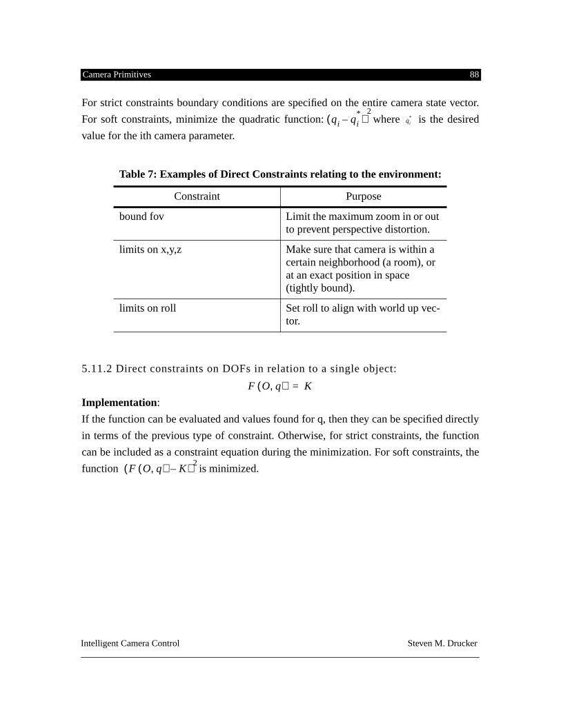
Camera Primitives 88
Intelligent Camera Control Steven M. Drucker
For strict constraints boundary conditions are specified on the entire camera state vector.
For soft constraints, minimize the quadratic function: where is the desired
value for the ith camera parameter.
5.11.2 Direct constraints on DOFs in relation to a single object:
Implementation
:
If the function can be evaluated and values found for q, then they can be specified directly
in terms of the previous type of constraint. Otherwise, for strict constraints, the function
can be included as a constraint equation during the minimization. For soft constraints, the
function is minimized.
Table 7: Examples of Direct Constraints relating to the environment:
Constraint Purpose
bound fov Limit the maximum zoom in or out to prevent perspective distortion.
limits on x,y,z Make sure that camera is within a certain neighborhood (a room), or at an exact position in space (tightly bound).
limits on roll Set roll to align with world up vec-tor.
qi qi*
–( )2
qi*
F O q,( )
K
=
F O q,( ) K–( ) 2
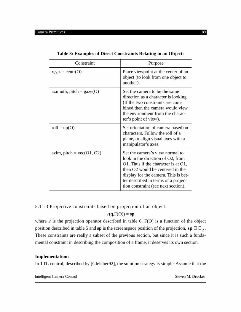
Camera Primitives 89
Intelligent Camera Control Steven M. Drucker
5.11.3 Projective constraints based on projection of an object:
P
(q,F(O)) =
sp
where
P
is the projection operator described in table 6, F(O) is a function of the object
position described in table 5 and
sp
is the screenspace position of the projection, .
These constraints are really a subset of the previous section, but since it is such a funda-
mental constraint in describing the composition of a frame, it deserves its own section.
Implementation:
In TTL control, described by [Gleicher92], the solution strategy is simple. Assume that the
Table 8: Examples of Direct Constraints Relating to an Object:
Constraint Purpose
x,y,z = centr(O) Place viewpoint at the center of an object (to look from one object to another).
azimuth, pitch = gaze(O) Set the camera to be the same direction as a character is looking. (If the two constraints are com-bined then the camera would view the environment from the charac-ter’s point of view).
roll = up(O) Set orientation of camera based on characters. Follow the roll of a plane, or align visual axes with a manipulator’s axes.
azim, pitch = vec(O1, O2) Set the camera’s view normal to look in the direction of O2, from O1. Thus if the character is at O1, then O2 would be centered in the display for the camera. This is bet-ter described in terms of a projec-tion constraint (see next section).
sp
ℜ
2
∈
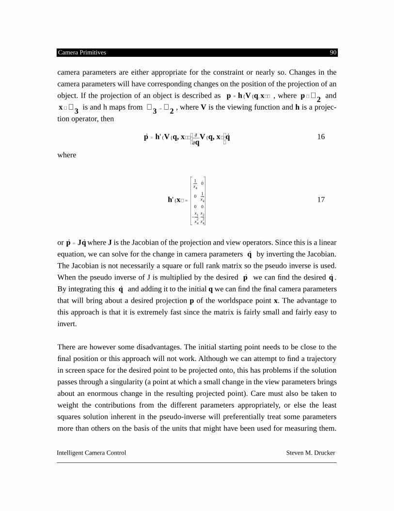
Camera Primitives 90
Intelligent Camera Control Steven M. Drucker
camera parameters are either appropriate for the constraint or nearly so. Changes in the
camera parameters will have corresponding changes on the position of the projection of an
object. If the projection of an object is described as , where and
is and h maps from , where
V
is the viewing function and
h
is a projec-
tion operator, then
16
where
17
or where
J
is the Jacobian of the projection and view operators. Since this is a linear
equation, we can solve for the change in camera parameters by inverting the Jacobian.
The Jacobian is not necessarily a square or full rank matrix so the pseudo inverse is used.
When the pseudo inverse of J is multiplied by the desired we can find the desired .
By integrating this and adding it to the initial
q
we can find the final camera parameters
that will bring about a desired projection
p
of the worldspace point
x
. The advantage to
this approach is that it is extremely fast since the matrix is fairly small and fairly easy to
invert.
There are however some disadvantages. The initial starting point needs to be close to the
final position or this approach will not work. Although we can attempt to find a trajectory
in screen space for the desired point to be projected onto, this has problems if the solution
passes through a singularity (a point at which a small change in the view parameters brings
about an enormous change in the resulting projected point). Care must also be taken to
weight the contributions from the different parameters appropriately, or else the least
squares solution inherent in the pseudo-inverse will preferentially treat some parameters
more than others on the basis of the units that might have been used for measuring them.
p h V q x
,( )( )= p
ℜ
2
∈
x
ℜ
3
∈ ℜ
3 ℜ
2
→
p h' V q x,( )( )q∂
∂ V q x,( ) q=
h' x( )
1x4----- 0
01x4-----
0 0
x1
x42
-----–x2
x42
-----
=
p
˙ Jq
˙
=
q
˙
p
˙ q
˙
q
˙
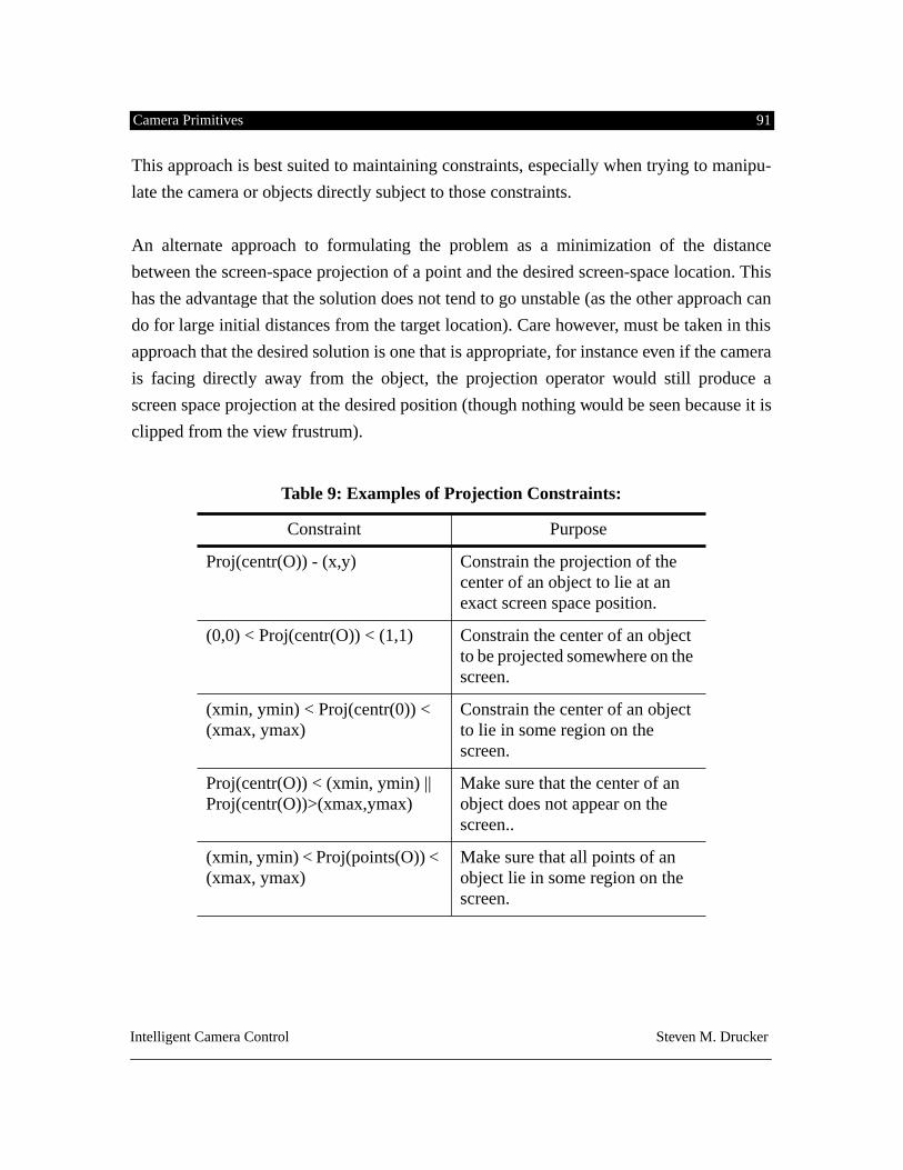
Camera Primitives 91
Intelligent Camera Control Steven M. Drucker
This approach is best suited to maintaining constraints, especially when trying to manipu-
late the camera or objects directly subject to those constraints.
An alternate approach to formulating the problem as a minimization of the distance
between the screen-space projection of a point and the desired screen-space location. This
has the advantage that the solution does not tend to go unstable (as the other approach can
do for large initial distances from the target location). Care however, must be taken in this
approach that the desired solution is one that is appropriate, for instance even if the camera
is facing directly away from the object, the projection operator would still produce a
screen space projection at the desired position (though nothing would be seen because it is
clipped from the view frustrum).
Table 9: Examples of Projection Constraints:
Constraint Purpose
Proj(centr(O)) - (x,y) Constrain the projection of the center of an object to lie at an exact screen space position.
(0,0) < Proj(centr(O)) < (1,1) Constrain the center of an object to be projected somewhere on the screen.
(xmin, ymin) < Proj(centr(0)) < (xmax, ymax)
Constrain the center of an object to lie in some region on the screen.
Proj(centr(O)) < (xmin, ymin) || Proj(centr(O))>(xmax,ymax)
Make sure that the center of an object does not appear on the screen..
(xmin, ymin) < Proj(points(O)) < (xmax, ymax)
Make sure that all points of an object lie in some region on the screen.
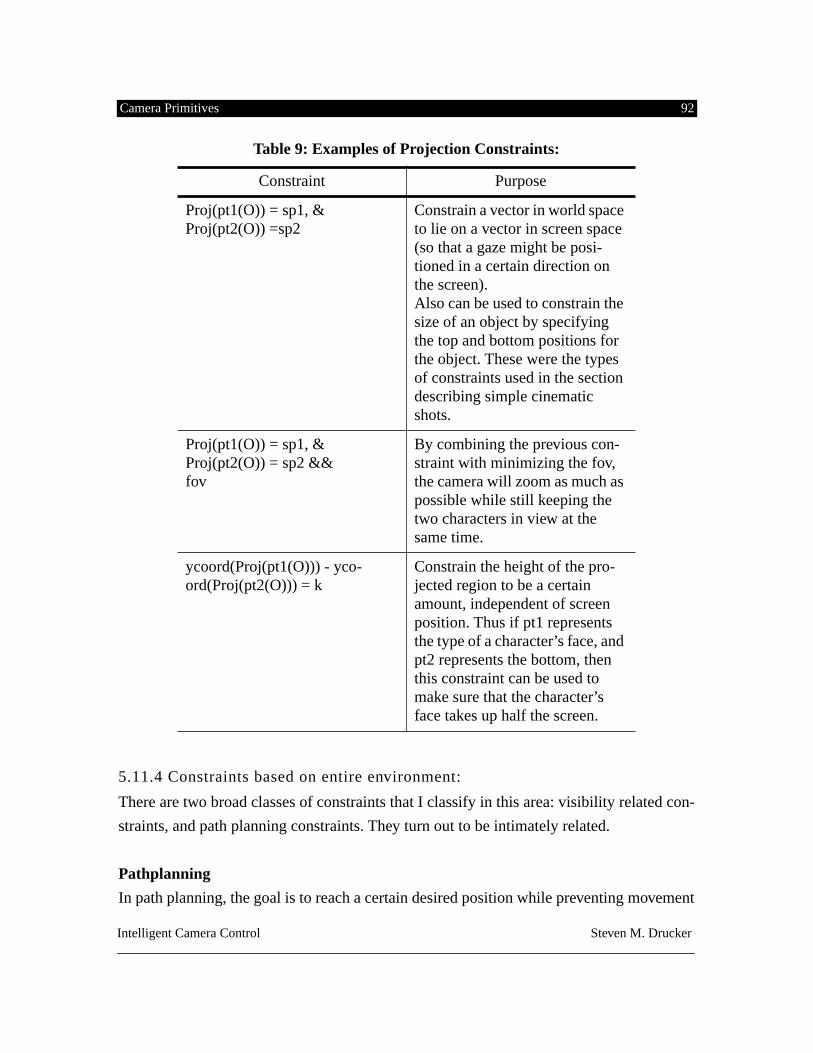
Camera Primitives 92
Intelligent Camera Control Steven M. Drucker
5.11.4 Constraints based on entire environment:
There are two broad classes of constraints that I classify in this area: visibility related con-
straints, and path planning constraints. They turn out to be intimately related.
Pathplanning
In path planning, the goal is to reach a certain desired position while preventing movement
Proj(pt1(O)) = sp1, & Proj(pt2(O)) =sp2
Constrain a vector in world space to lie on a vector in screen space (so that a gaze might be posi-tioned in a certain direction on the screen).Also can be used to constrain the size of an object by specifying the top and bottom positions for the object. These were the types of constraints used in the section describing simple cinematic shots.
Proj(pt1(O)) = sp1, & Proj(pt2(O)) = sp2 &&fov
By combining the previous con-straint with minimizing the fov, the camera will zoom as much as possible while still keeping the two characters in view at the same time.
ycoord(Proj(pt1(O))) - yco-ord(Proj(pt2(O))) = k
Constrain the height of the pro-jected region to be a certain amount, independent of screen position. Thus if pt1 represents the type of a character’s face, and pt2 represents the bottom, then this constraint can be used to make sure that the character’s face takes up half the screen.
Table 9: Examples of Projection Constraints:
Constraint Purpose
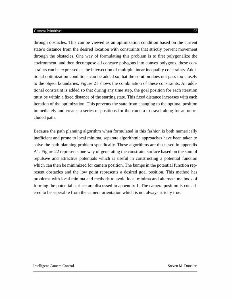
Camera Primitives 93
Intelligent Camera Control Steven M. Drucker
through obstacles. This can be viewed as an optimization condition based on the current
state’s distance from the desired location with constraints that strictly prevent movement
through the obstacles. One way of formulating this problem is to first polygonalize the
environment, and then decompose all concave polygons into convex polygons, these con-
straints can be expressed as the intersection of multiple linear inequality constraints. Addi-
tional optimization conditions can be added so that the solution does not pass too closely
to the object boundaries. Figure 21 shows the combination of these constraints. An addi-
tional constraint is added so that during any time step, the goal position for each iteration
must be within a fixed distance of the starting state. This fixed distance increases with each
iteration of the optimization. This prevents the state from changing to the optimal position
immediately and creates a series of positions for the camera to travel along for an unoc-
cluded path.
Because the path planning algorithm when formulated in this fashion is both numerically
inefficient and prone to local minima, separate algorithmic approaches have been taken to
solve the path planning problem specifically. These algorithms are discussed in appendix
A1. Figure 22 represents one way of generating the constraint surface based on the sum of
repulsive and attractive potentials which is useful in constructing a potential function
which can then be minimized for camera position. The bumps in the potential function rep-
resent obstacles and the low point represents a desired goal position. This method has
problems with local minima and methods to avoid local minima and alternate methods of
forming the potential surface are discussed in appendix 1. The camera position is consid-
ered to be seperable from the camera orientation which is not always strictly true.
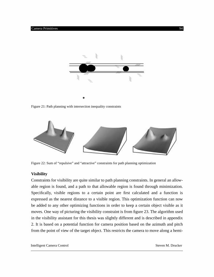
Camera Primitives 94
Intelligent Camera Control Steven M. Drucker
Figure 21: Path planning with intersection inequality constraints
Figure 22: Sum of “repulsive” and “attractive” constraints for path planning optimization
Visibility
Constraints for visibility are quite similar to path planning constraints. In general an allow-
able region is found, and a path to that allowable region is found through minimization.
Specifically, visible regions to a certain point are first calculated and a function is
expressed as the nearest distance to a visible region. This optimization function can now
be added to any other optimizing functions in order to keep a certain object visible as it
moves. One way of picturing the visibility constraint is from figure 23. The algorithm used
in the visibility assistant for this thesis was slightly different and is described in appendix
2. It is based on a potential function for camera position based on the azimuth and pitch
from the point of view of the target object. This restricts the camera to move along a hemi-
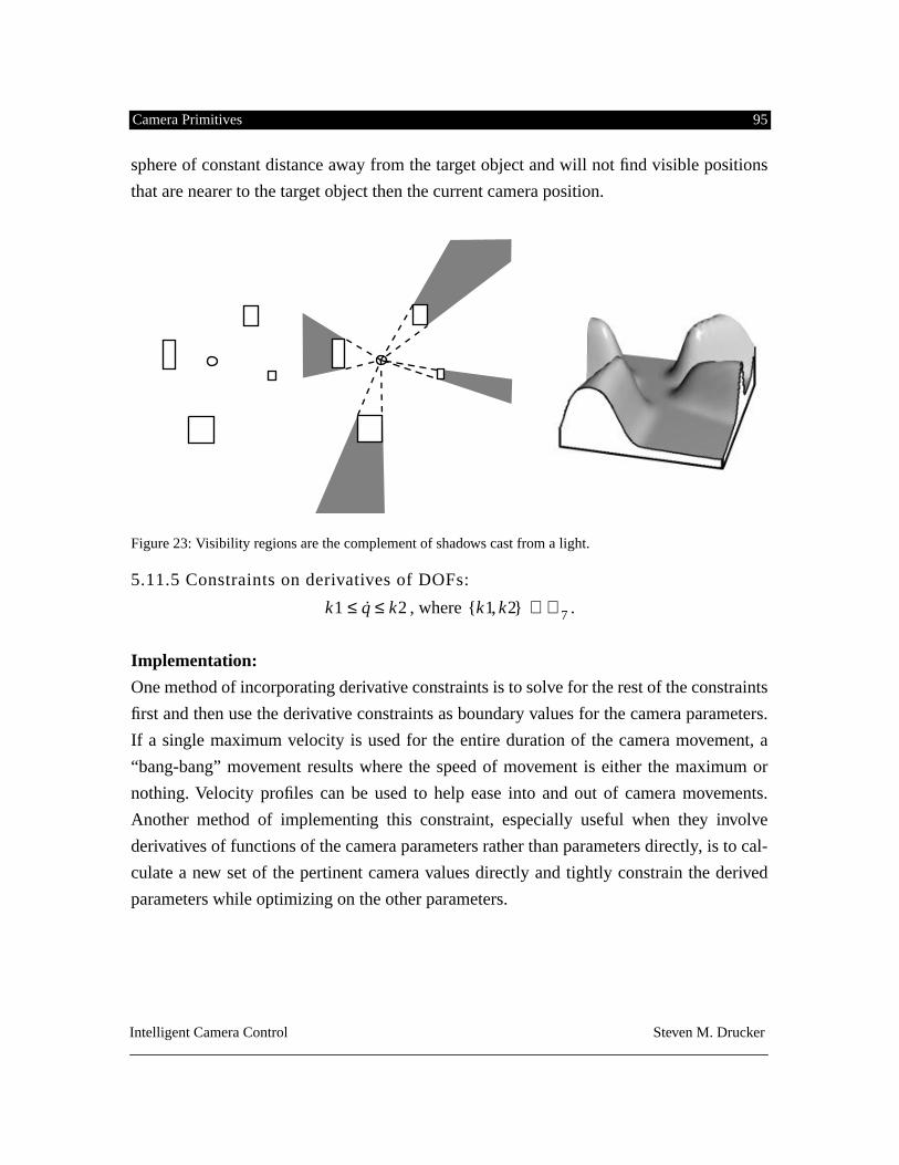
Camera Primitives 95
Intelligent Camera Control Steven M. Drucker
sphere of constant distance away from the target object and will not find visible positions
that are nearer to the target object then the current camera position.
Figure 23: Visibility regions are the complement of shadows cast from a light.
5.11.5 Constraints on derivatives of DOFs:
, where .
Implementation:
One method of incorporating derivative constraints is to solve for the rest of the constraints
first and then use the derivative constraints as boundary values for the camera parameters.
If a single maximum velocity is used for the entire duration of the camera movement, a
“bang-bang” movement results where the speed of movement is either the maximum or
nothing. Velocity profiles can be used to help ease into and out of camera movements.
Another method of implementing this constraint, especially useful when they involve
derivatives of functions of the camera parameters rather than parameters directly, is to cal-
culate a new set of the pertinent camera values directly and tightly constrain the derived
parameters while optimizing on the other parameters.
k
1 q k2
≤ ≤ k1 k2{ , }
ℜ
7
∈
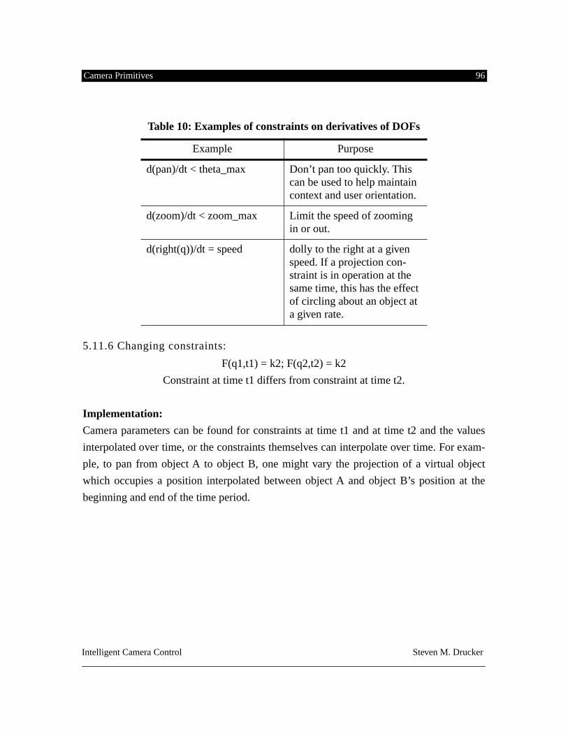
Camera Primitives 96
Intelligent Camera Control Steven M. Drucker
5.11.6 Changing constraints:
F(q1,t1) = k2; F(q2,t2) = k2
Constraint at time t1 differs from constraint at time t2.
Implementation:
Camera parameters can be found for constraints at time t1 and at time t2 and the values
interpolated over time, or the constraints themselves can interpolate over time. For exam-
ple, to pan from object A to object B, one might vary the projection of a virtual object
which occupies a position interpolated between object A and object B’s position at the
beginning and end of the time period.
Table 10: Examples of constraints on derivatives of DOFs
Example Purpose
d(pan)/dt < theta_max Don’t pan too quickly. This can be used to help maintain context and user orientation.
d(zoom)/dt < zoom_max Limit the speed of zooming in or out.
d(right(q))/dt = speed dolly to the right at a given speed. If a projection con-straint is in operation at the same time, this has the effect of circling about an object at a given rate.
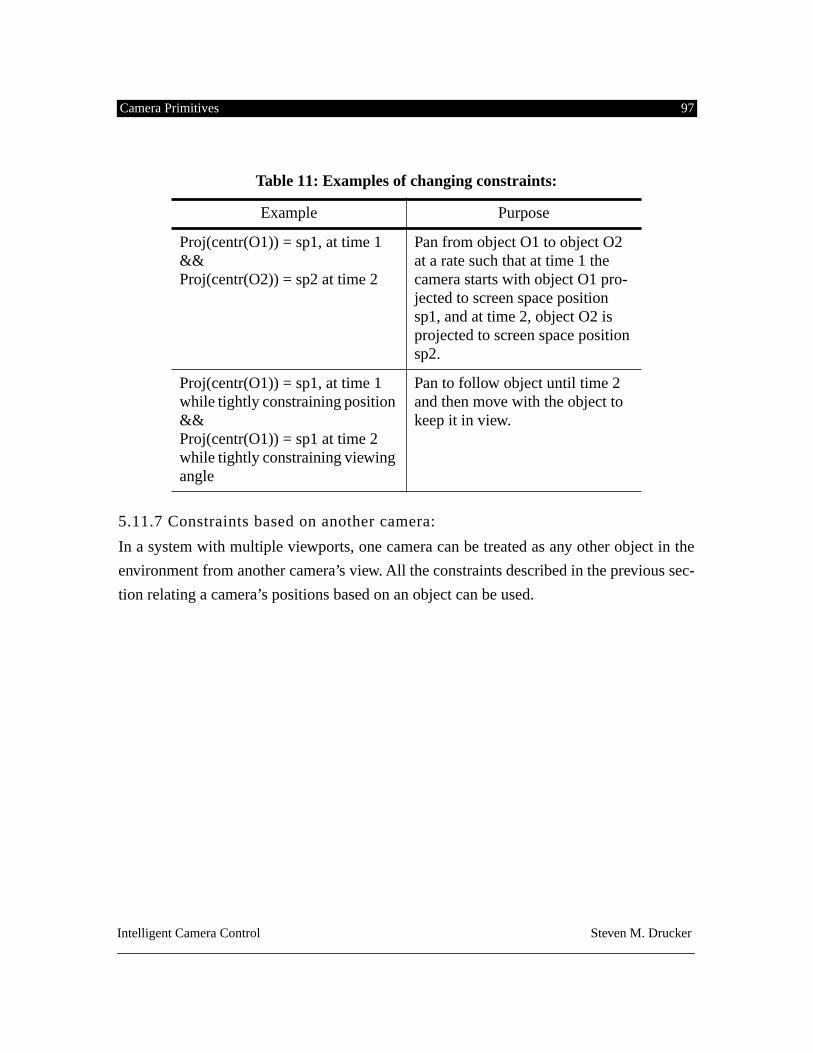
Camera Primitives 97
Intelligent Camera Control Steven M. Drucker
5.11.7 Constraints based on another camera:
In a system with multiple viewports, one camera can be treated as any other object in the
environment from another camera’s view. All the constraints described in the previous sec-
tion relating a camera’s positions based on an object can be used.
Table 11: Examples of changing constraints:
Example Purpose
Proj(centr(O1)) = sp1, at time 1 && Proj(centr(O2)) = sp2 at time 2
Pan from object O1 to object O2 at a rate such that at time 1 the camera starts with object O1 pro-jected to screen space position sp1, and at time 2, object O2 is projected to screen space position sp2.
Proj(centr(O1)) = sp1, at time 1 while tightly constraining position && Proj(centr(O1)) = sp1 at time 2 while tightly constraining viewing angle
Pan to follow object until time 2 and then move with the object to keep it in view.
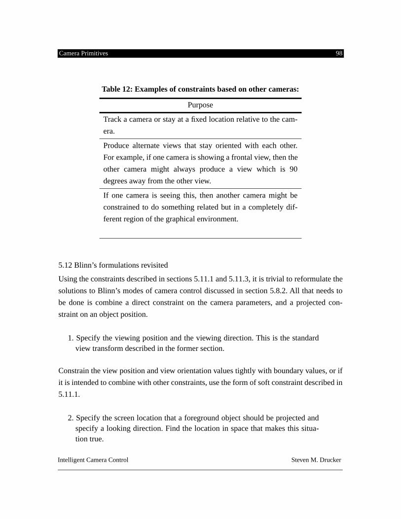
Camera Primitives 98
Intelligent Camera Control Steven M. Drucker
5.12 Blinn’s formulations revisited
Using the constraints described in sections 5.11.1 and 5.11.3, it is trivial to reformulate the
solutions to Blinn’s modes of camera control discussed in section 5.8.2. All that needs to
be done is combine a direct constraint on the camera parameters, and a projected con-
straint on an object position.
1. Specify the viewing position and the viewing direction. This is the standardview transform described in the former section.
Constrain the view position and view orientation values tightly with boundary values, or if
it is intended to combine with other constraints, use the form of soft constraint described in
5.11.1.
2. Specify the screen location that a foreground object should be projected andspecify a looking direction. Find the location in space that makes this situa-tion true.
Table 12: Examples of constraints based on other cameras:
Purpose
Track a camera or stay at a fixed location relative to the cam-
era.
Produce alternate views that stay oriented with each other.
For example, if one camera is showing a frontal view, then the
other camera might always produce a view which is 90
degrees away from the other view.
If one camera is seeing this, then another camera might be
constrained to do something related but in a completely dif-
ferent region of the graphical environment.
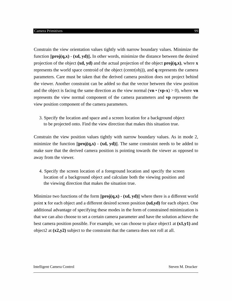
Camera Primitives 99
Intelligent Camera Control Steven M. Drucker
Constrain the view orientation values tightly with narrow boundary values. Minimize the
function
||proj(q,x)
-
(xd, yd)||.
In other words, minimize the distance between the desired
projection of the object
(xd, yd)
and the actual projection of the object
proj(q,x)
, where
x
represents the world space centroid of the object (centr(obj)), and
q
represents the camera
parameters. Care must be taken that the derived camera position does not project behind
the viewer. Another constraint can be added so that the vector between the view position
and the object is facing the same direction as the view normal (
vn
• (
vp
-
x
) > 0), where
vn
represents the view normal component of the camera parameters and
vp
represents the
view position component of the camera parameters.
3. Specify the location and space and a screen location for a background objectto be projected onto. Find the view direction that makes this situation true.
Constrain the view position values tightly with narrow boundary values. As in mode 2,
minimize the function
||proj(q,x)
-
(xd, yd)||
. The same constraint needs to be added to
make sure that the derived camera position is pointing towards the viewer as opposed to
away from the viewer.
4. Specify the screen location of a foreground location and specify the screenlocation of a background object and calculate both the viewing position andthe viewing direction that makes the situation true.
Minimize two functions of the form
||proj(q,x)
-
(xd, yd)||
where there is a different world
point
x
for each object and a different desired screen position
(xd,yd)
for each object. One
additional advantage of specifying these modes in the form of constrained minimization is
that we can also choose to set a certain camera parameter and have the solution achieve the
best camera position possible. For example, we can choose to place object1 at
(x1,y1)
and
object2 at
(x2,y2)
subject to the constraint that the camera does not roll at all.
From Task to Interface 100
Intelligent Camera Control Steven M. Drucker
CHAPTER 6. FROM TASK TO INTERFACE
Previous chapters discussed a taxonomy of domains, several styles of interaction in each
domain were examined, and camera primitives were formally expressed in a constrained
optimization framework. This section is devoted to an analysis of five specific applications
and the development of interfaces for controlling the camera to accomplish tasks in each.
The applications were chosen to illustrate a wide variety of types of interfaces that can be
built on top of the constraint framework, and to demonstrate the fact that the framework’s
utility can span a sufficiently representative sampling of application domains.
The applications discussed here are a
Virtual Museum, a Mission Planning System, a Vir-
tual Conversation Assistant, a Virtual Football Game, and a Visibility Assistant. The Virtual
Museum was used to examine an example in an exploratory domain. The Mission Planner
is an instance of a task from the rehearsal domain. The Virtual Conversation Assistant and
the Virtual Football Game are both tasks primarily from the planning domain, and the Vis-
ibility Assistant is a prototypical control domain task. Styles of interaction range from
extremely tight coupling between the user and the degrees of freedom of the camera via a
head mounted display or joystick control, to semi-autonomous path finding through a
space, to a reactive camera agent which senses and responds to changes in the environ-
ment. A visual programming interface is also discussed to combine and sequence camera
behaviors by dragging initial conditions, constraints, and controllers into camera agents.
6.1 Example: The Virtual Museum
Our first domain is the Virtual Museum [Drucker94]. A museum was chosen since it is a
visually rich, spatially organized, information space [Miller92]. It is important to note that
the museum represents any spatially organized database, and some tasks that might seem
From Task to Interface 101
Intelligent Camera Control Steven M. Drucker
nonsensical in the museum domain do make sense in an alternate, but similar domain. One
alternate domain might be the exploration of data about a human body compiled from a
variety of medical scans. This domain emphasizes the importance of the spatial organiza-
tion of data. A well designed museum uses this spatial organization to make effective state-
ments on the content [Sand94].
We divide the kinds of tasks that we wish to perform in the spatial database into two essen-
tial categories: exploring and navigating. By exploring, I mean a general search for infor-
mation but not necessarily specific information. By navigating, I mean moving to a
specific location within the environment. Orienting oneself is an important component for
both of these categories.
Examples of the basic tasks that comprise the museum are shown in the following table.
Equivalent tasks for medical exploration are also shown. This medical exploration might
be either an examination of pre-gathered medical data, or perhaps on-line control of an
arthroscope. The latter might be more suitably described as a control-oriented task, but
since the primary goal here is to gather information, I will consider it in this section.
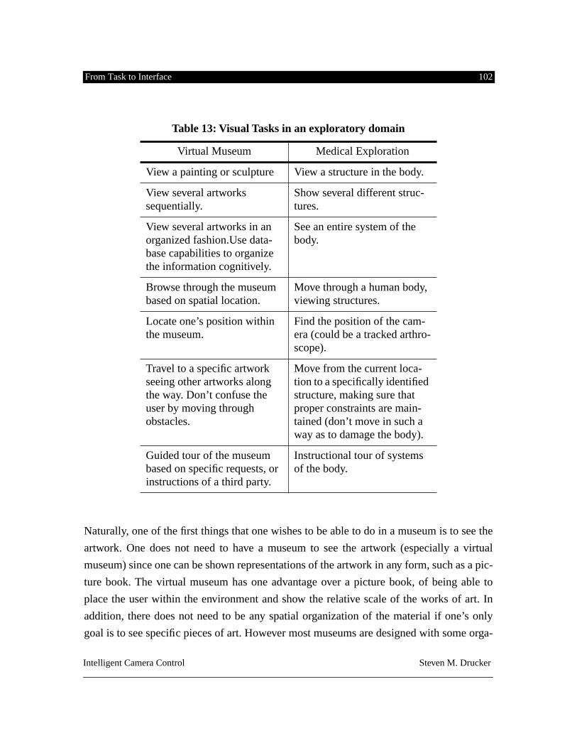
From Task to Interface 102
Intelligent Camera Control Steven M. Drucker
Naturally, one of the first things that one wishes to be able to do in a museum is to see the
artwork. One does not need to have a museum to see the artwork (especially a virtual
museum) since one can be shown representations of the artwork in any form, such as a pic-
ture book. The virtual museum has one advantage over a picture book, of being able to
place the user within the environment and show the relative scale of the works of art. In
addition, there does not need to be any spatial organization of the material if one’s only
goal is to see specific pieces of art. However most museums are designed with some orga-
Table 13: Visual Tasks in an exploratory domain
Virtual Museum Medical Exploration
View a painting or sculpture View a structure in the body.
View several artworks sequentially.
Show several different struc-tures.
View several artworks in an organized fashion.Use data-base capabilities to organize the information cognitively.
See an entire system of the body.
Browse through the museum based on spatial location.
Move through a human body, viewing structures.
Locate one’s position within the museum.
Find the position of the cam-era (could be a tracked arthro-scope).
Travel to a specific artwork seeing other artworks along the way. Don’t confuse the user by moving through obstacles.
Move from the current loca-tion to a specifically identified structure, making sure that proper constraints are main-tained (don’t move in such a way as to damage the body).
Guided tour of the museum based on specific requests, or instructions of a third party.
Instructional tour of systems of the body.
From Task to Interface 103
Intelligent Camera Control Steven M. Drucker
nizing principles, and the virtual museum allows the spatial organization to be perceived
directly. The equivalent task in the medical domain is to look at a particular organ that has
been already isolated.Ssince it might be difficult to isolate a structure, spatially moving
through the body might be the best way to see that structure.
Another purpose of examining the museum might be to become familiar with the spatial
layout as a prelude to visiting a real museum. In this case, a means of browsing through the
space of the museum is necessary. However, if the controls for browsing the space are too
obtrusive, the system forces the user to pay more attention to the controls than to browsing
the space itself. For example, often, one does not get to see a new city if one has to drive
through the city and pay more attention to the traffic and the street signs in order to get to a
particular destination. One can sit on a tour bus and have a better view of the surroundings.
Alternately, many people complain that if they don’t do the controlling, they never are able
to find their way through the environment without assistance later. No one solution to all
tasks is appropriate, so an interface must support a wide range of different styles of inter-
action.
It is interesting to note that the spatial layout of space can be used as an organizing princi-
ple for human memory [Miller72]. Associating objects with positions along a path through
a museum can aid in their recall. This same spatial organizing principle can serve to help
enhance the experience of viewing the artwork.
Finally, the user might wish to be taken on a guided tour through the museum seeing dif-
ferent artwork in sequence. Again, this could be done through a picture book, but by being
able to compare sizes of work in context can enhance the experience.
6.1.1 Implementation
The museum was designed in such a way that task assistants can be added as individual
camera modules
. A camera module is an encapsulation of the camera primitives along
with some other interface components including initial conditions, controllers, and local
state. As can be clearly seen from the description above, no one interface is best suited to
performing all tasks. By expressing the task assistants in terms of combinable primitives,
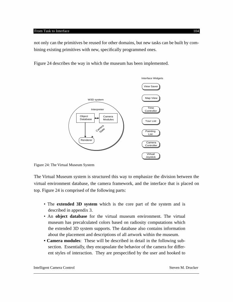
From Task to Interface 104
Intelligent Camera Control Steven M. Drucker
not only can the primitives be reused for other domains, but new tasks can be built by com-
bining existing primitives with new, specifically programmed ones.
Figure 24 describes the way in which the museum has been implemented.
Figure 24: The Virtual Museum System
The Virtual Museum system is structured this way to emphasize the division between the
virtual environment database, the camera framework, and the interface that is placed on
top. Figure 24 is comprised of the following parts:
• The
extended 3D system
which is the core part of the system and isdescribed in appendix 3.
• An
object database
for the virtual museum environment. The virtualmuseum has precalculated colors based on radiosity computations whichthe extended 3D system supports. The database also contains informationabout the placement and descriptions of all artwork within the museum.
• Camera modules
: These will be described in detail in the following sub-section. Essentially, they encapsulate the behavior of the camera for differ-ent styles of interaction. They are prespecified by the user and hooked to
W3D system
Renderer
Object Database
Camera Modules
Interpreter
Interface Widgets
Map View
View Saver
Time Controller
Painting List
Tour List
Camera Controller
Virtual Joystick
Camera
State
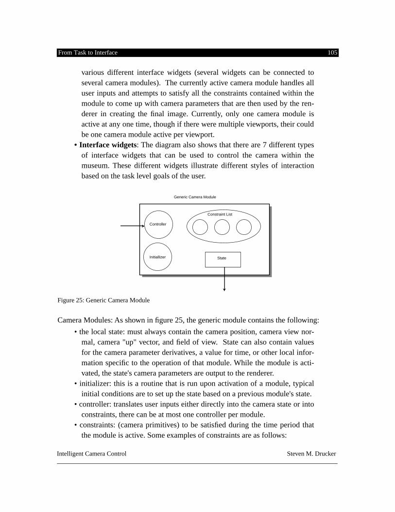
From Task to Interface 105
Intelligent Camera Control Steven M. Drucker
various different interface widgets (several widgets can be connected toseveral camera modules). The currently active camera module handles alluser inputs and attempts to satisfy all the constraints contained within themodule to come up with camera parameters that are then used by the ren-derer in creating the final image. Currently, only one camera module isactive at any one time, though if there were multiple viewports, their couldbe one camera module active per viewport.
• Interface widgets
: The diagram also shows that there are 7 different typesof interface widgets that can be used to control the camera within themuseum. These different widgets illustrate different styles of interactionbased on the task level goals of the user.
Figure 25: Generic Camera Module
Camera Modules: As shown in figure 25, the generic module contains the following:
• the local state: must always contain the camera position, camera view nor-mal, camera "up" vector, and field of view. State can also contain valuesfor the camera parameter derivatives, a value for time, or other local infor-mation specific to the operation of that module. While the module is acti-vated, the state's camera parameters are output to the renderer.
• initializer: this is a routine that is run upon activation of a module, typicalinitial conditions are to set up the state based on a previous module's state.
• controller: translates user inputs either directly into the camera state or intoconstraints, there can be at most one controller per module.
• constraints: (camera primitives) to be satisfied during the time period thatthe module is active. Some examples of constraints are as follows:
Controller
Initiallizer State
Constraint List
Generic Camera Module
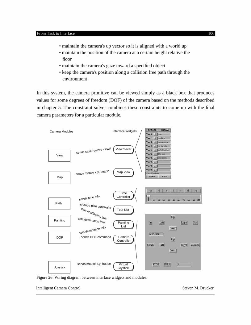
From Task to Interface 106
Intelligent Camera Control Steven M. Drucker
• maintain the camera's up vector so it is aligned with a world up • maintain the position of the camera at a certain height relative the
floor • maintain the camera's gaze toward a specified object • keep the camera's position along a collision free path through the
environment
In this system, the camera primitive can be viewed simply as a black box that produces
values for some degrees of freedom (DOF) of the camera based on the methods described
in chapter 5. The constraint solver combines these constraints to come up with the final
camera parameters for a particular module.
Figure 26: Wiring diagram between interface widgets and modules.
Interface WidgetsCamera Modules
Map View
View Saver
TimeController
PaintingList
Tour List
CameraController
VirtualJoystick
Map
View
Path
sends mouse x,y, button
sends mouse x,y, button
sends save/restore view#
sends time info
change plan constraint
sets destination info
sets destination infosets destination infoPainting
DOF
Joystick
sends DOF command
From Task to Interface 107
Intelligent Camera Control Steven M. Drucker
In the Virtual Museum system, camera modules are activated by selecting the correspond-
ing interface widget. This widget also passes information to the controller of the module.
The "wiring diagram" which shows what information is sent from the interface to the cor-
responding module, and which module is activated when the user presses an interface wid-
get is shown in figure 26. A single line means that information is transferred from the
widget to the corresponding module. A double line indicates that the widget activates the
corresponding module.
Here is a description of what occurs when the user clicks on the
map view
widget
. First,
the corresponding map view module is activated, which means that this module's state will
be used during rendering. The initializer for this module grabs the camera state from the
previous module thus allowing the user to control the camera using one set of controls, and
then adjust the position further using the map view. This module's controller maps the
(x,y) position of the user's mouse click along with the corresponding button directly into a
constraint on the current state of the camera. The
view saver's
module either grabs the cur-
rent view and saves it as part of the local state information for that module, or retrieves a
saved view from the local state information and sets the camera parameters based on that.
The
joystick module's
controller maps the x & y location of the viewer's mouse click into
constraints on the velocity of the virtual camera’s motion through the environment. There
is an additional constraint in the joystick module that prevents movement through walls.
The
painting list
is connected to several different modules. One module's controller (the
paint module) responds to a double click of the middle mouse button and sets its state
based on the painting's position in the environment. In addition, a constraint is added to
the DOF controller module that constrains the camera to point toward the specified paint-
ing. When double clicking with the left button, not only is this constraint added to the DOF
controller module, but source information and destination information is added to the local
state of the
path
module
. The source information is based on the current state of the cam-
era, the destination is based on the position of the painting in the environment. The
path
module
contains a constraint which uses this local information to construct a collision free
path through the environment from the initial state to the specified final position. The algo-
rithm used by the path planner is described in detail in appendix 1.
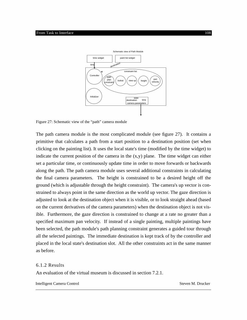
From Task to Interface 108
Intelligent Camera Control Steven M. Drucker
Figure 27: Schematic view of the “path” camera module
The path camera module is the most complicated module (see figure 27). It contains a
primitive that calculates a path from a start position to a destination position (set when
clicking on the painting list). It uses the local state's time (modified by the time widget) to
indicate the current position of the camera in the (x,y) plane. The time widget can either
set a particular time, or continuously update time in order to move forwards or backwards
along the path. The path camera module uses several additional constraints in calculating
the final camera parameters. The height is constrained to be a desired height off the
ground (which is adjustable through the height constraint). The camera's up vector is con-
strained to always point in the same direction as the world up vector. The gaze direction is
adjusted to look at the destination object when it is visible, or to look straight ahead (based
on the current derivatives of the camera parameters) when the destination object is not vis-
ible. Furthermore, the gaze direction is constrained to change at a rate no greater than a
specified maximum pan velocity. If instead of a single painting, multiple paintings have
been selected, the path module's path planning constraint generates a guided tour through
all the selected paintings. The immediate destination is kept track of by the controller and
placed in the local state's destination slot. All the other constraints act in the same manner
as before.
6.1.2 Results
An evaluation of the virtual museum is discussed in section 7.2.1.
Schematic view of Path Module
path plan
constraint
statedestination time
lookat view up height
camera parameters
pan velocity
constraint list
Initializer
Controller
time widget paint list widget
destinationtime
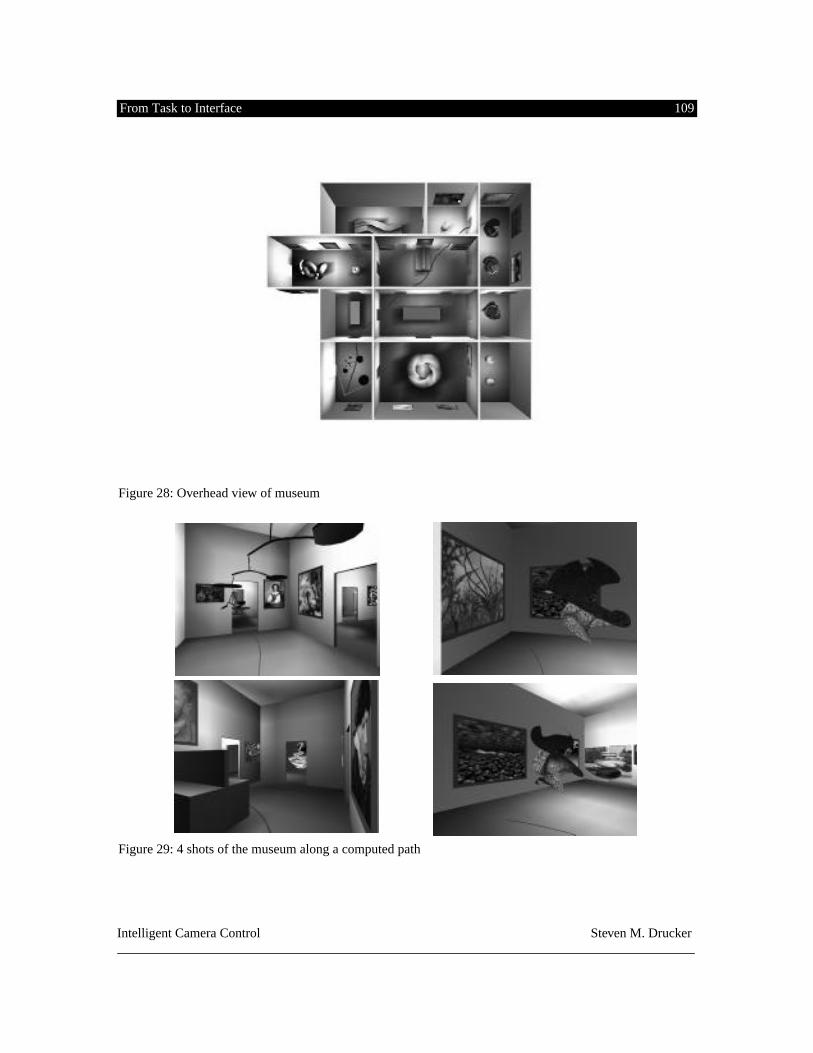
From Task to Interface 109
Intelligent Camera Control Steven M. Drucker
Figure 28: Overhead view of museum
Figure 29: 4 shots of the museum along a computed path
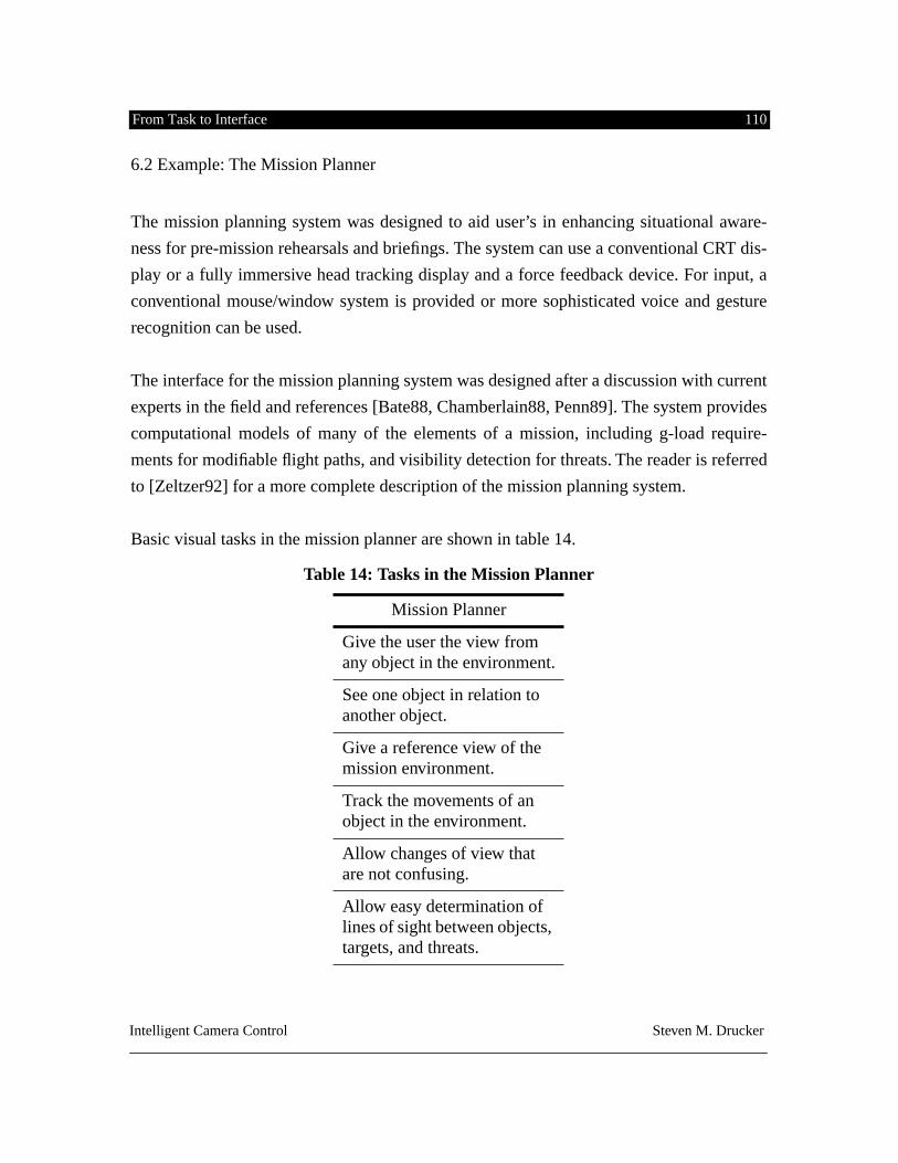
From Task to Interface 110
Intelligent Camera Control Steven M. Drucker
6.2 Example: The Mission Planner
The mission planning system was designed to aid user’s in enhancing situational aware-
ness for pre-mission rehearsals and briefings. The system can use a conventional CRT dis-
play or a fully immersive head tracking display and a force feedback device. For input, a
conventional mouse/window system is provided or more sophisticated voice and gesture
recognition can be used.
The interface for the mission planning system was designed after a discussion with current
experts in the field and references [Bate88, Chamberlain88, Penn89]. The system provides
computational models of many of the elements of a mission, including g-load require-
ments for modifiable flight paths, and visibility detection for threats. The reader is referred
to [Zeltzer92] for a more complete description of the mission planning system.
Basic visual tasks in the mission planner are shown in table 14.
Table 14: Tasks in the Mission Planner
Mission Planner
Give the user the view from any object in the environment.
See one object in relation to another object.
Give a reference view of the mission environment.
Track the movements of an object in the environment.
Allow changes of view that are not confusing.
Allow easy determination of lines of sight between objects, targets, and threats.
From Task to Interface 111
Intelligent Camera Control Steven M. Drucker
The camera control that is implemented in the mission planning system has two main
requirements: 1) easy and convenient symbolic specification for the camera, and 2) main-
tain the user’s awareness of the current context. One important aspect of the interface for
the mission planner was the use of a head mounted display to provide immersion within
the environment. Because of the immersion, the best way to operate the controls was via
voice commands, since the hands were no longer able to operate a mouse/menu system.
Using the voice necessitated mapping user’s requests into a small set of concise commands
which can be issued over the voice recognition system. The following commands are sup-
ported: saving and restoring views, panning, zooming, trucking, dollying, craning, tilting,
rolling, look at an object, look from an object, “over-the-shoulder” from object 1 to object
2.
The look at object constrains the projection of the object to appear at the same position on
the screen either as the viewpoint moves (if the user’s view is already attached to an
object) or as the object of interest moves. The look from an object constrains the virtual
camera to be at a certain point within the cockpit of an airplane (or within a tank). If the
user is not already looking at another object, the view vector is constrained to be along the
direction of flight of the plane while constraining the view up vector to be aligned with the
up vector of the plane (which banks for turns). The “over-the-shoulder” shots can be
implemented with the same constraints that are used in an over-the-shoulder shot in a con-
versation (see section 5.3).
The second requirement prevents the system from changing the view too rapidly which
might make it difficult to maintain context in the system. An additional constraint is added
which specifies a maximum change of any of the camera parameters from one frame to
another. The camera state will change this maximum amount and converge to the desired
value over several frames. This permits panning from one object of interest to another
object of interest, or moving the viewpoint from one point to another without losing con-
text.
Lastly, a rudimentary visibility constraint has been added to the system which tests
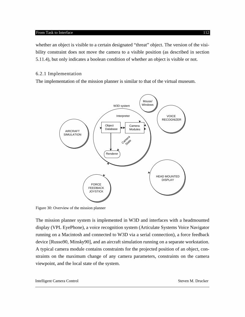
From Task to Interface 112
Intelligent Camera Control Steven M. Drucker
whether an object is visible to a certain designated “threat” object. The version of the visi-
bility constraint does not move the camera to a visible position (as described in section
5.11.4), but only indicates a boolean condition of whether an object is visible or not.
6.2.1 Implementation
The implementation of the mission planner is similar to that of the virtual museum.
Figure 30: Overview of the mission planner
The mission planner system is implemented in W3D and interfaces with a headmounted
display (VPL EyePhone), a voice recognition system (Articulate Systems Voice Navigator
running on a Macintosh and connected to W3D via a serial connection), a force feedback
device [Russo90, Minsky90], and an aircraft simulation running on a separate workstation.
A typical camera module contains constraints for the projected position of an object, con-
straints on the maximum change of any camera parameters, constraints on the camera
viewpoint, and the local state of the system.
W3D system
Renderer
ObjectDatabase
CameraModules
Interpreter
Camer
a
State
HEAD MOUNTEDDISPLAY
VOICE RECOGNIZER
AIRCRAFTSIMULATION
Mouse/Windows
FORCEFEEDBACKJOYSTICK
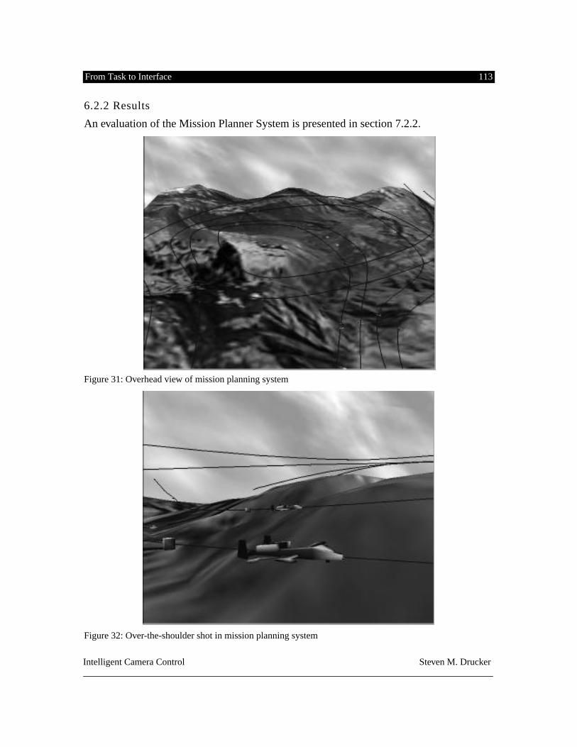
From Task to Interface 113
Intelligent Camera Control Steven M. Drucker
6.2.2 Results
An evaluation of the Mission Planner System is presented in section 7.2.2.
Figure 31: Overhead view of mission planning system
Figure 32: Over-the-shoulder shot in mission planning system
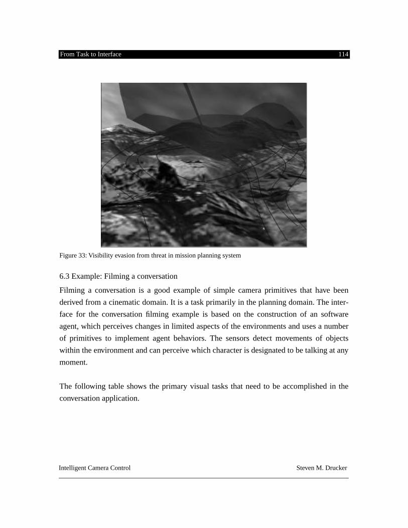
From Task to Interface 114
Intelligent Camera Control Steven M. Drucker
Figure 33: Visibility evasion from threat in mission planning system
6.3 Example: Filming a conversation
Filming a conversation is a good example of simple camera primitives that have been
derived from a cinematic domain. It is a task primarily in the planning domain. The inter-
face for the conversation filming example is based on the construction of an software
agent, which perceives changes in limited aspects of the environments and uses a number
of primitives to implement agent behaviors. The sensors detect movements of objects
within the environment and can perceive which character is designated to be talking at any
moment.
The following table shows the primary visual tasks that need to be accomplished in the
conversation application.
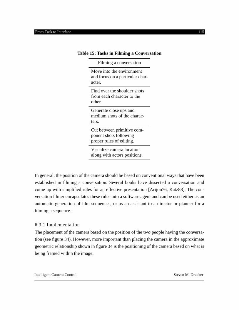
From Task to Interface 115
Intelligent Camera Control Steven M. Drucker
In general, the position of the camera should be based on conventional ways that have been
established in filming a conversation. Several books have dissected a conversation and
come up with simplified rules for an effective presentation [Arijon76, Katz88]. The con-
versation filmer encapsulates these rules into a software agent and can be used either as an
automatic generation of film sequences, or as an assistant to a director or planner for a
filming a sequence.
6.3.1 Implementation
The placement of the camera based on the position of the two people having the conversa-
tion (see figure 34). However, more important than placing the camera in the approximate
geometric relationship shown in figure 34 is the positioning of the camera based on what is
being framed within the image.
Table 15: Tasks in Filming a Conversation
Filming a conversation
Move into the environment and focus on a particular char-acter.
Find over the shoulder shots from each character to the other.
Generate close ups and medium shots of the charac-ters.
Cut between primitive com-ponent shots following proper rules of editing.
Visualize camera location along with actors positions.
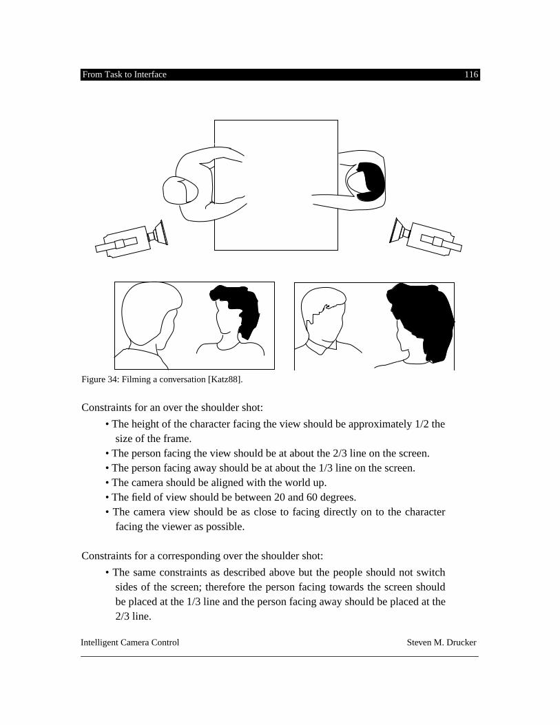
From Task to Interface 116
Intelligent Camera Control Steven M. Drucker
Figure 34: Filming a conversation [Katz88].
Constraints for an over the shoulder shot:
• The height of the character facing the view should be approximately 1/2 thesize of the frame.
• The person facing the view should be at about the 2/3 line on the screen.• The person facing away should be at about the 1/3 line on the screen.• The camera should be aligned with the world up.• The field of view should be between 20 and 60 degrees.• The camera view should be as close to facing directly on to the character
facing the viewer as possible.
Constraints for a corresponding over the shoulder shot:
• The same constraints as described above but the people should not switchsides of the screen; therefore the person facing towards the screen shouldbe placed at the 1/3 line and the person facing away should be placed at the2/3 line.
From Task to Interface 117
Intelligent Camera Control Steven M. Drucker
The diagram can be used to find the initial positions of the cameras if necessary, but the
constraint solver should make sure that the composition of the screen is as desired.
The Conversation Software Agent
This is a prototypical agent with fairly little intelligence, but kept simple to illustrate the
design decisions. The agent contains a rudiementary reactive planner which pairs camera
behaviors (combination of camera primitives) in response to sensed data. The agent will
have two camera behaviors: one for when character 1 (Steven) is speaking; and one for
when character 2 (David) is speaking. The agent needs to have sensors which can “detect”
who is speaking and direct the corresponding camera behavior to occur. The agent can also
sense the position of any of the characters in the environment.
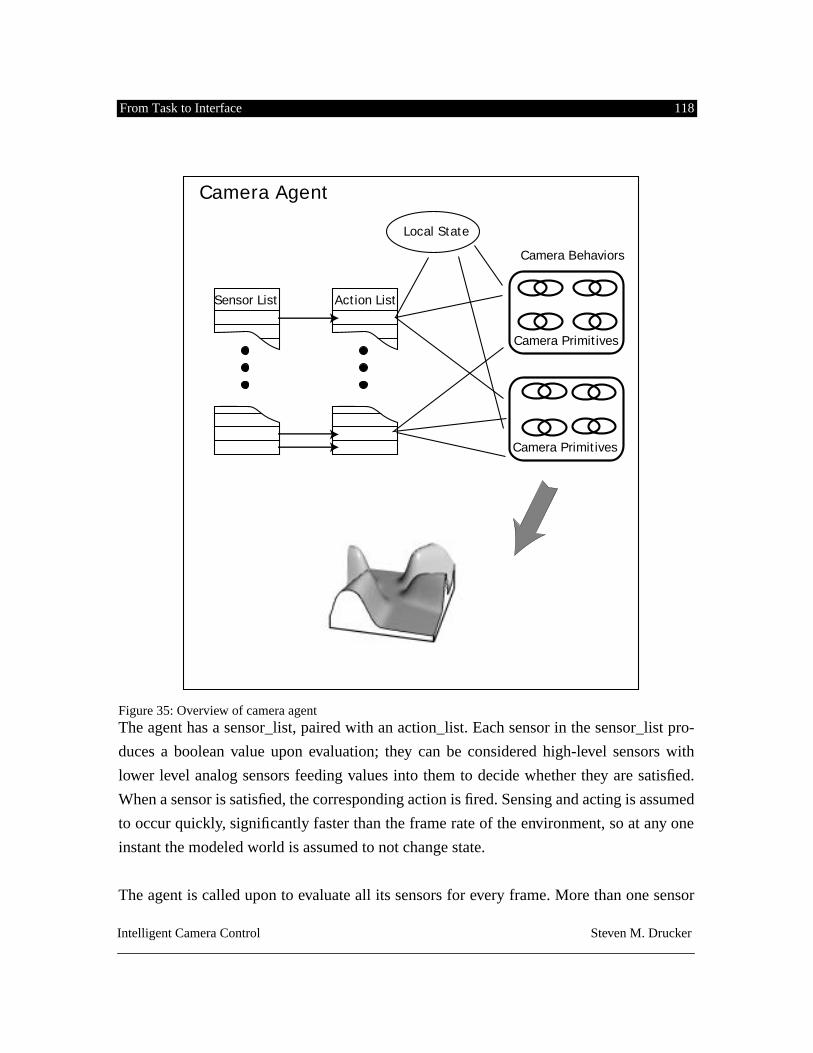
From Task to Interface 118
Intelligent Camera Control Steven M. Drucker
Figure 35: Overview of camera agent
The agent has a sensor_list, paired with an action_list. Each sensor in the sensor_list pro-
duces a boolean value upon evaluation; they can be considered high-level sensors with
lower level analog sensors feeding values into them to decide whether they are satisfied.
When a sensor is satisfied, the corresponding action is fired. Sensing and acting is assumed
to occur quickly, significantly faster than the frame rate of the environment, so at any one
instant the modeled world is assumed to not change state.
The agent is called upon to evaluate all its sensors for every frame. More than one sensor
Sensor List Action List
Camera Primitives
Camera Primitives
Camera Agent
Local State
Camera Behaviors
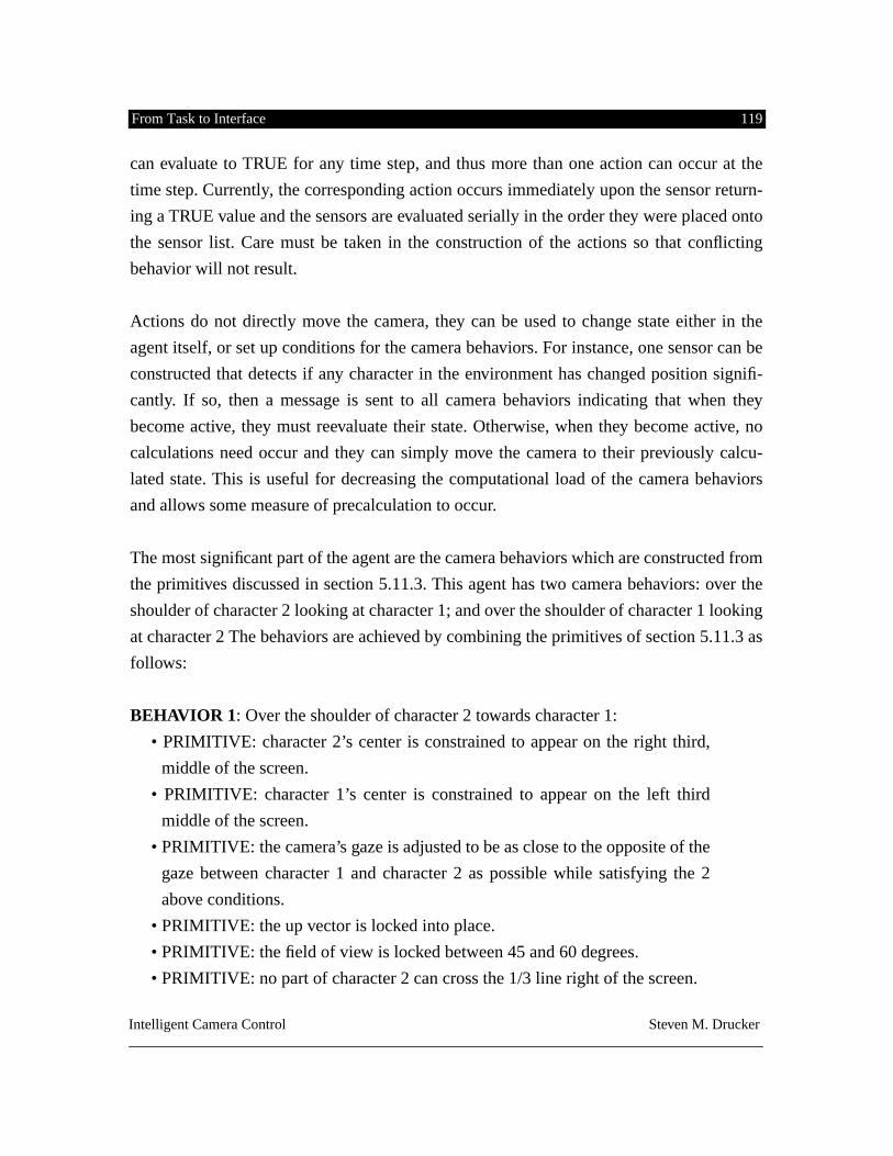
From Task to Interface 119
Intelligent Camera Control Steven M. Drucker
can evaluate to TRUE for any time step, and thus more than one action can occur at the
time step. Currently, the corresponding action occurs immediately upon the sensor return-
ing a TRUE value and the sensors are evaluated serially in the order they were placed onto
the sensor list. Care must be taken in the construction of the actions so that conflicting
behavior will not result.
Actions do not directly move the camera, they can be used to change state either in the
agent itself, or set up conditions for the camera behaviors. For instance, one sensor can be
constructed that detects if any character in the environment has changed position signifi-
cantly. If so, then a message is sent to all camera behaviors indicating that when they
become active, they must reevaluate their state. Otherwise, when they become active, no
calculations need occur and they can simply move the camera to their previously calcu-
lated state. This is useful for decreasing the computational load of the camera behaviors
and allows some measure of precalculation to occur.
The most significant part of the agent are the camera behaviors which are constructed from
the primitives discussed in section 5.11.3. This agent has two camera behaviors: over the
shoulder of character 2 looking at character 1; and over the shoulder of character 1 looking
at character 2 The behaviors are achieved by combining the primitives of section 5.11.3 as
follows:
BEHAVIOR 1
: Over the shoulder of character 2 towards character 1:
• PRIMITIVE: character 2’s center is constrained to appear on the right third,
middle of the screen.
• PRIMITIVE: character 1’s center is constrained to appear on the left third
middle of the screen.
• PRIMITIVE: the camera’s gaze is adjusted to be as close to the opposite of the
gaze between character 1 and character 2 as possible while satisfying the 2
above conditions.
• PRIMITIVE: the up vector is locked into place.
• PRIMITIVE: the field of view is locked between 45 and 60 degrees.
• PRIMITIVE: no part of character 2 can cross the 1/3 line right of the screen.
From Task to Interface 120
Intelligent Camera Control Steven M. Drucker
• PRIMITIVE: no part of character 1 can cross the 1/3 line right of the screen
from the other side.
• PRIMITIVE: the camera is pointed in the general direction towards character
1 as opposed to away from character 1.
• PRIMITIVE: the camera is pointed in the general direction towards character
2 as opposed to away from character 2.
BEHAVIOR 2
: Over the shoulder of character 1 towards character 2. This is the exact
opposite of the behavior 1, but with the projected positions of the objects remaining on the
same sides of the screen. This prevents passing over the 180 degree line from shot to shot.
• PRIMITIVE: character2’s center is constrained to appear on the right third,
middle of the screen. (same as in behavior 1)
• PRIMITIVE: character1’s center is constrained to appear on the left third mid-
dle of the screen. (same as in behavior 1)
• PRIMITIVE: the camera’s gaze is adjusted to be as close to the opposite of the
gaze between character 2 and character 1 as possible while satisfying the 2
above conditions. (This is the opposite of behavior 1)
• PRIMITIVE: the up vector is locked into place. (same)
• PRIMITIVE: the field of view is locked between 45 and 60 degrees. (same)
• PRIMITIVE: no part of character 2 can cross the 1/3 line left of the screen
(opposite side of screen)
• PRIMITIVE: no part of character 1 can cross the 1/3 line left of the screen
from the other side.(opposite side of screen)
• PRIMITIVE: the camera is pointed in the general direction towards character
1 as opposed to away from character 1.
• PRIMITIVE: the camera is pointed in the general direction towards character
2 as opposed to away from character 2.
An additional behavior can be added that might be used as an establishing shot, or a shot
when neither of the two people are talking. This would be a two shot of the two characters
facing each other.
From Task to Interface 121
Intelligent Camera Control Steven M. Drucker
BEHAVIOR 3
: Side view of characters:
• PRIMITIVE: character 2’s center is constrained to appear on the right third,
middle of the screen. (same)
• PRIMITIVE: character 1’s center is constrained to appear on the left third
middle of the screen.(same)
• PRIMITIVE: the camera’s gaze is adjusted to be as close to perpendicular to
the gaze between character 2 and character 1 as possible while satisfying the 2
above conditions. (This is different from behaviors 1 and 2)
• PRIMITiVE: the up vector is locked into place (same)
• PRIMITIVE: the field of view is locked between 45 and 60 degrees. (same)
• PRIMITIVE: no part of character 2 can cross the center line right of the screen
(center of screen)
• PRIMITIVE: no part of character 1 can cross the center line right of the screen
from the other side.(center of screen)
• PRIMITIVE: the camera is pointed in the general direction towards character
1 as opposed to away from character 1.
• PRIMITIVE: the camera is pointed in the general direction towards character
2 as opposed to away from character 2.
A deeper analysis of the way that the primitives are combined is in order. From behavior 1,
we can classify the different kinds of primitives into 2 different categories: soft constraints
(those constraints that do not need to be met exactly), only the best solution need be found
among conflicting constraints; and hard constraints (those constraints that need to be satis-
fied exactly).
First, for the “soft” constraints that don’t need to be satisfied at the same time, the solution
will try to minimize the maximum of these constraints at any one time. In this behavior, it
is not possible to place the center of object 1 at a certain place, AND the center of object 2
at a certain place while making the camera gaze along the vector between object 1 and
object 2 (the only way for this last condition to be true is if the center of object 1 and the
center for object 2 were projected to the SAME point on the screen). Thus these three
From Task to Interface 122
Intelligent Camera Control Steven M. Drucker
primitives are formulated into an optimization problem where the system tries to minimize
the maximum of any violations of these constraints.
The next category of primitives are those for which the solution would be INCORRECT if
the constraint is violated (hard constraints). The broad category is further subdivided into
several types. There are bounds on the individual degrees of freedom for the camera: make
the roll angle equal to 0 (equality); keep the field of view between 45 and 60 degrees (ine-
quality). There are constraints on multiple degrees of freedom of the camera: look towards
the object as opposed to away (this constraint is necessary due to the fact that it is mathe-
matically equivalent for a projection of an object to be from behind the camera as it is to be
in front of the camera). There are also inequality constraints based on the projection of an
object: make sure that no part of the object 1 appears on the left hand side of the screen and
no part of object 2 appears on the right hand side of the screen.
The advantage of designing the camera agent in the fashion described above is that the
camera agent is reactive. By reactive, I mean that the agent can be set into any environment
in which its sensors can work and it can locate the positions of the characters and it will
film the actions in the manner specified. If the characters change positions, it will still
manage to frame the characters in an acceptable fashion or inform the user when the con-
straints can not be satisfied. Thus, this agent is reusable across a wide range of environ-
ments, containing no special parameters that would make it only appropriate for a single
particular environment. The behaviors encapsulate reasonably accepted cinematic rules,
and the process of sensing and acting makes the agent automatically construct a sequence
of shots in the style specified in figure 34.
6.3.2 Extensions to agents:
Care was taken in constructing the behaviors so that implicitly no cinematic rules were
violated. Sensor action pairings can be made more sophisticated so that sensors can check
the existing camera state so that no action which will violate a cinematic rule will be sub-
sequently fired.
All the actions described above dealt with discontinuously changing the camera parame-
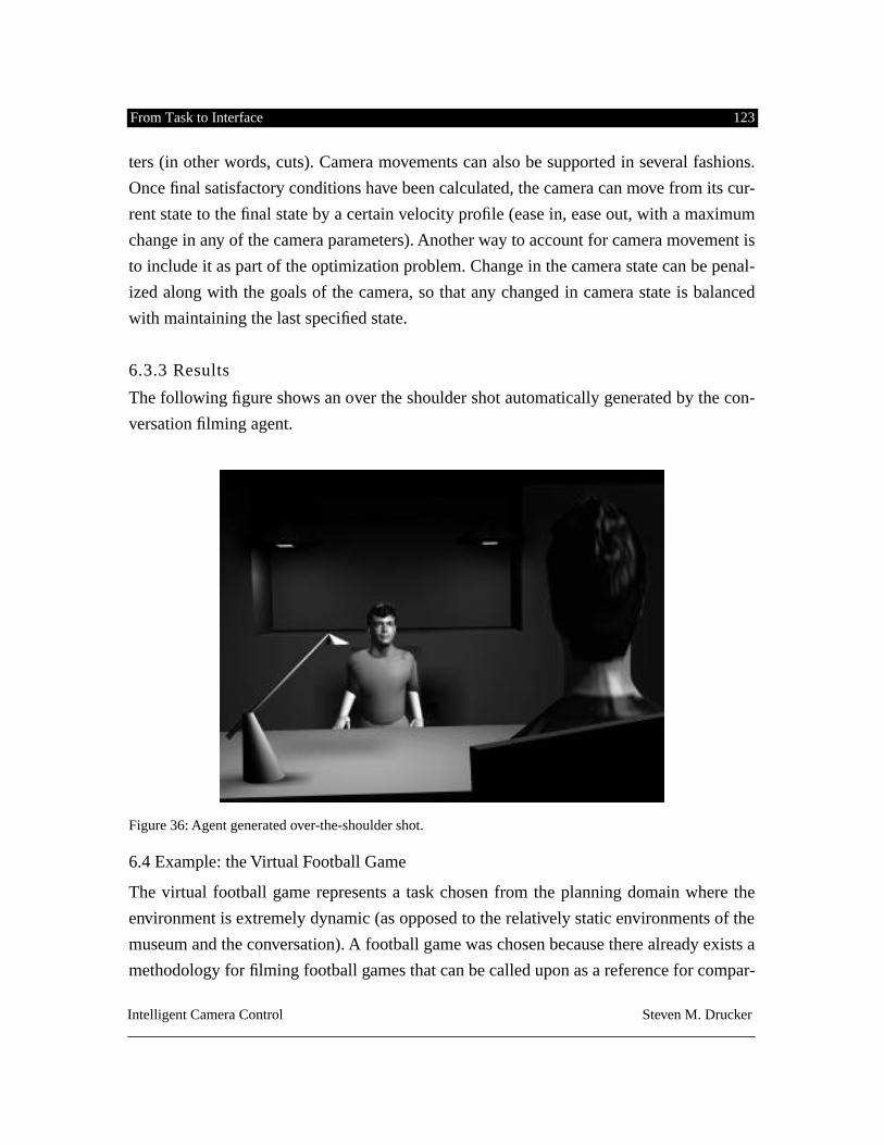
From Task to Interface 123
Intelligent Camera Control Steven M. Drucker
ters (in other words, cuts). Camera movements can also be supported in several fashions.
Once final satisfactory conditions have been calculated, the camera can move from its cur-
rent state to the final state by a certain velocity profile (ease in, ease out, with a maximum
change in any of the camera parameters). Another way to account for camera movement is
to include it as part of the optimization problem. Change in the camera state can be penal-
ized along with the goals of the camera, so that any changed in camera state is balanced
with maintaining the last specified state.
6.3.3 Results
The following figure shows an over the shoulder shot automatically generated by the con-
versation filming agent.
Figure 36: Agent generated over-the-shoulder shot.
6.4 Example: the Virtual Football Game
The virtual football game represents a task chosen from the planning domain where the
environment is extremely dynamic (as opposed to the relatively static environments of the
museum and the conversation). A football game was chosen because there already exists a
methodology for filming football games that can be called upon as a reference for compar-
From Task to Interface 124
Intelligent Camera Control Steven M. Drucker
ing the controls and resultant output of the virtual football game. Also, the temporal flow
of the football game is convenient since it contains starting and stopping points, specific
kinds of choreographed movements, and easily identifiable participants. In addition, a
visual programming language for combining camera primitives into camera behaviors was
explored. Finally, an interface, on top of the visual programming language, based directly
on the way that a conventional football game is filmed was developed.
It is important to note that there are significant differences between the virtual football
game and filming a real football game. Although attempts were made to make the virtual
football game realistic; three-dimensional video images of players were incorporated and
football plays were based on real plays [Korch90], this virtual football game is intended as
a testbed for intelligent camera control and not a real football game. In the first case, we
are not currently concerned with controlling robotic cameras, since there are a host of
other constraints that would need to be implemented to deal with speed and configura-
tional limitations that we can ignore. In the virtual game, the system has complete knowl-
edge about the entire environment, both in terms of where all the objects are in the present
and where they will be in the future, it knows when the ball will be thrown, and when it
will be caught. The user has complete control over the passage of time in the virtual foot-
ball game, being able to stop it, reverse it, speed up or slow down. The virtual cameras for
visualizing the football game can move to anywhere, including within another object or
flying along side it. The system can ignore any of this information, or constrain the abili-
ties of the virtual cameras, as appropriate to the test that is being performed.
The basic visual tasks in the virtual football game are as follows:
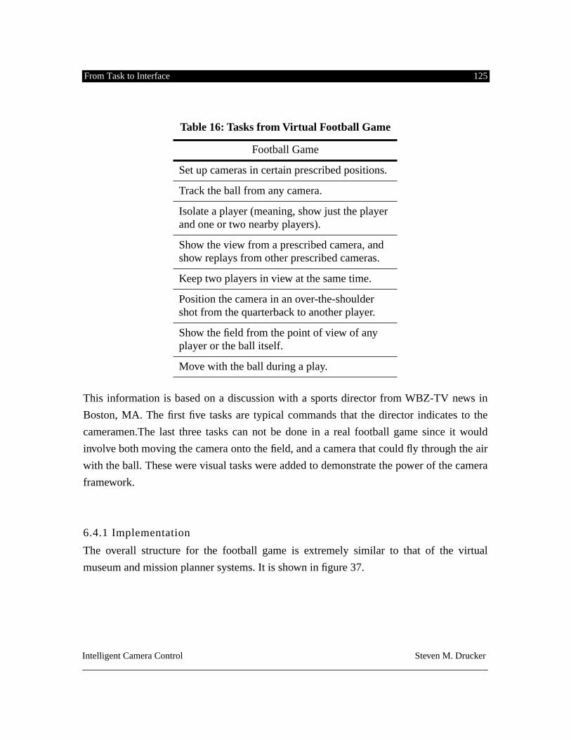
From Task to Interface 125
Intelligent Camera Control Steven M. Drucker
This information is based on a discussion with a sports director from WBZ-TV news in
Boston, MA. The first five tasks are typical commands that the director indicates to the
cameramen.The last three tasks can not be done in a real football game since it would
involve both moving the camera onto the field, and a camera that could fly through the air
with the ball. These were visual tasks were added to demonstrate the power of the camera
framework.
6.4.1 Implementation
The overall structure for the football game is extremely similar to that of the virtual
museum and mission planner systems. It is shown in figure 37.
Table 16: Tasks from Virtual Football Game
Football Game
Set up cameras in certain prescribed positions.
Track the ball from any camera.
Isolate a player (meaning, show just the player and one or two nearby players).
Show the view from a prescribed camera, and show replays from other prescribed cameras.
Keep two players in view at the same time.
Position the camera in an over-the-shoulder shot from the quarterback to another player.
Show the field from the point of view of any player or the ball itself.
Move with the ball during a play.
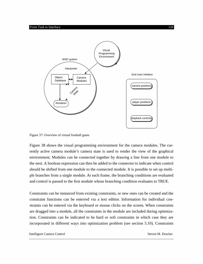
From Task to Interface 126
Intelligent Camera Control Steven M. Drucker
Figure 37: Overview of virtual football game
Figure 38 shows the visual programming environment for the camera modules. The cur-
rently active camera module’s camera state is used to render the view of the graphical
environment. Modules can be connected together by drawing a line from one module to
the next. A boolean expression can then be added to the connector to indicate when control
should be shifted from one module to the connected module. It is possible to set up multi-
ple branches from a single module. At each frame, the branching conditions are evaluated
and control is passed to the first module whose branching condition evaluates to TRUE.
Constraints can be instanced from existing constraints, or new ones can be created and the
constraint functions can be enterred via a text edittor. Information for individual con-
straints can be entered via the keyboard or mouse clicks on the screen. When constraints
are dragged into a module, all the constraints in the module are included during optimiza-
tion. Constraints can be indicated to be hard or soft constraints in which case they are
incorporated in different ways into optimization problem (see section 5.10). Constraints
W3D system
Renderer
ObjectDatabase
CameraModules
Interpreter
Camer
a
State
Visual ProgrammingEnvironment
End User Inteface
playback controls
player positions
camera positions
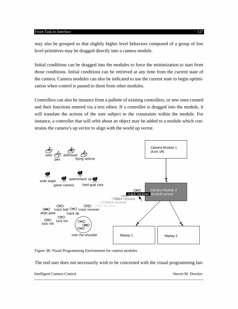
From Task to Interface 127
Intelligent Camera Control Steven M. Drucker
may also be grouped so that slightly higher level behaviors composed of a group of low
level primitives may be dragged directly into a camera module.
Initial conditions can be dragged into the modules to force the minimization to start from
those conditions. Initial conditions can be retrieved at any time from the current state of
the camera. Camera modules can also be indicated to use the current state to begin optimi-
zation when control is passed to them from other modules.
Controllers can also be instance from a pallette of existing controllers, or new ones created
and their functions entered via a text editor. If a controller is dragged into the module, it
will translate the actions of the user subject to the constraints within the module. For
instance, a controller that will orbit about an object may be added to a module which con-
strains the camera’s up vector to align with the world up vector.
Figure 38: Visual Programming Environment for camera modules
The end user does not necessarily wish to be concerned with the visual programming lan-
Camera Module 1 (kick off)
orbitpan
dollhouseflying vehicle
wide anglegame camera
quarterback vp
field goal cam
track ball
lock roll
align gaze track qbtrack receiver
track receivertrack receiver
track receiver
lock fov
over the shoulder
Camera Module 2 (kickoff return)track receiver
Replay 1 Replay 2
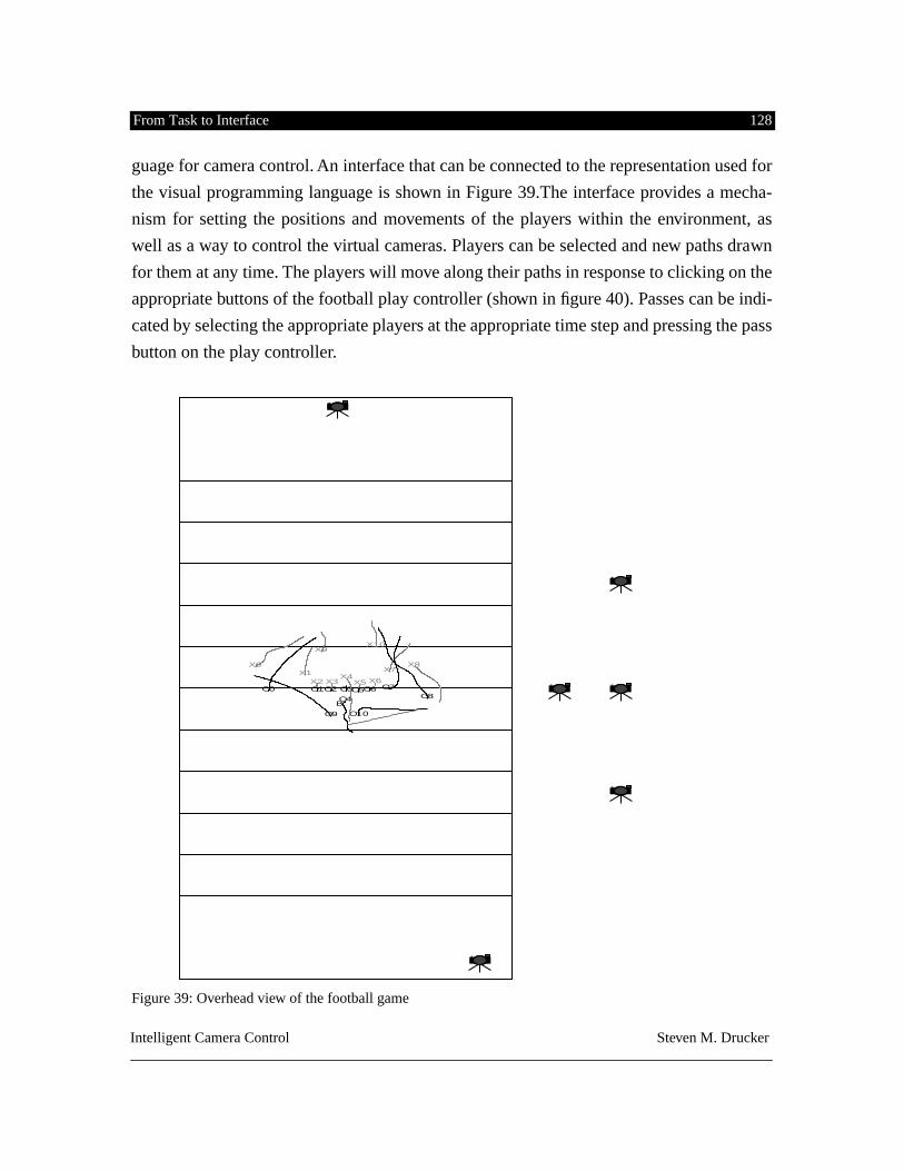
From Task to Interface 128
Intelligent Camera Control Steven M. Drucker
guage for camera control. An interface that can be connected to the representation used for
the visual programming language is shown in Figure 39.The interface provides a mecha-
nism for setting the positions and movements of the players within the environment, as
well as a way to control the virtual cameras. Players can be selected and new paths drawn
for them at any time. The players will move along their paths in response to clicking on the
appropriate buttons of the football play controller (shown in figure 40). Passes can be indi-
cated by selecting the appropriate players at the appropriate time step and pressing the pass
button on the play controller.
Figure 39: Overhead view of the football game
X0X1
X2 X3X4
X5 X6
X7X8
X9X10
O0 O1O2 O3
O4O5O6 O7
O8
O9 O10
B
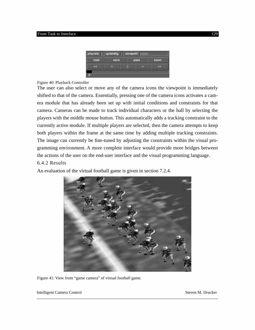
From Task to Interface 129
Intelligent Camera Control Steven M. Drucker
Figure 40: Playback Controller
The user can also select or move any of the camera icons the viewpoint is immediately
shifted to that of the camera. Essentially, pressing one of the camera icons activates a cam-
era module that has already been set up with initial conditions and constraints for that
camera. Cameras can be made to track individual characters or the ball by selecting the
players with the middle mouse button. This automatically adds a tracking constraint to the
currently active module. If multiple players are selected, then the camera attempts to keep
both players within the frame at the same time by adding multiple tracking constraints.
The image can currently be fine-tuned by adjusting the constraints within the visual pro-
gramming environment. A more complete interface would provide more bridges between
the actions of the user on the end-user interface and the visual programming language.
6.4.2 Results
An evaluation of the virtual football game is given in section 7.2.4.
Figure 41: View from “game camera” of virtual football game.
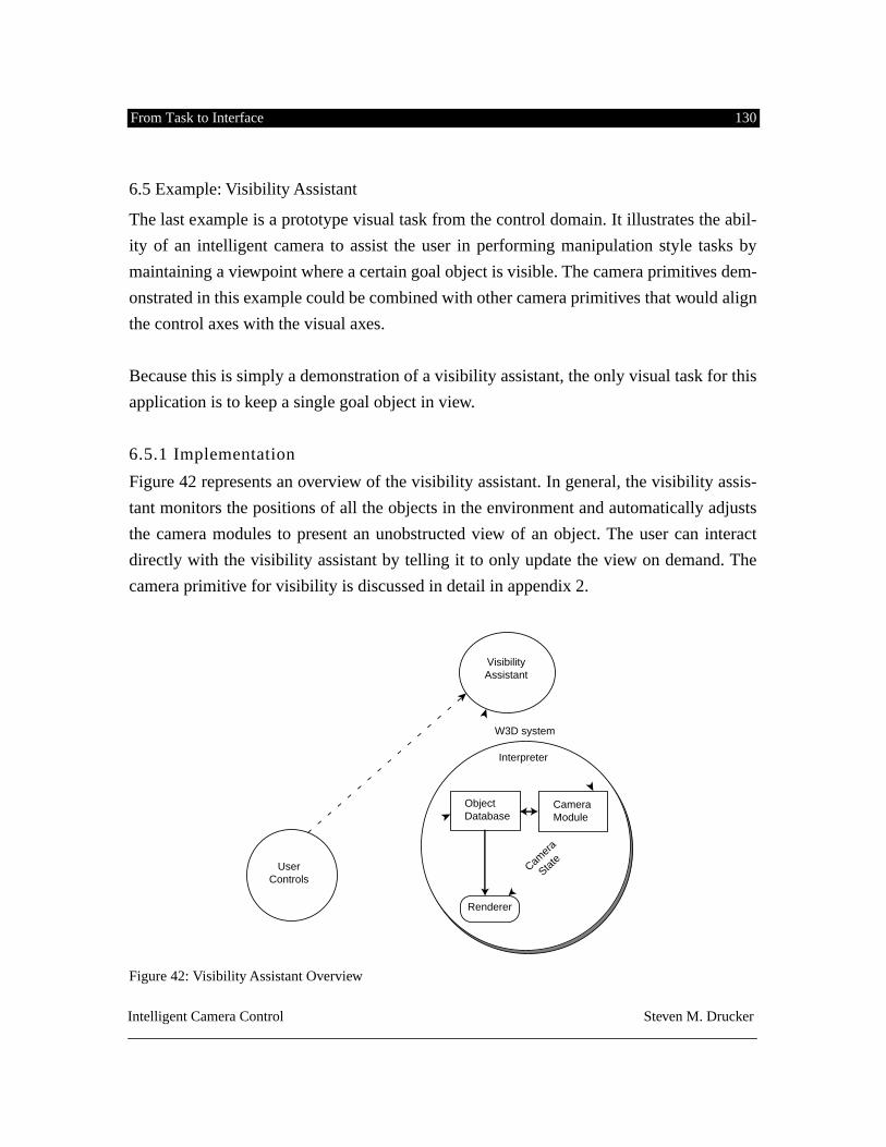
From Task to Interface 130
Intelligent Camera Control Steven M. Drucker
6.5 Example: Visibility Assistant
The last example is a prototype visual task from the control domain. It illustrates the abil-
ity of an intelligent camera to assist the user in performing manipulation style tasks by
maintaining a viewpoint where a certain goal object is visible. The camera primitives dem-
onstrated in this example could be combined with other camera primitives that would align
the control axes with the visual axes.
Because this is simply a demonstration of a visibility assistant, the only visual task for this
application is to keep a single goal object in view.
6.5.1 Implementation
Figure 42 represents an overview of the visibility assistant. In general, the visibility assis-
tant monitors the positions of all the objects in the environment and automatically adjusts
the camera modules to present an unobstructed view of an object. The user can interact
directly with the visibility assistant by telling it to only update the view on demand. The
camera primitive for visibility is discussed in detail in appendix 2.
Figure 42: Visibility Assistant Overview
W3D system
Renderer
ObjectDatabase
CameraModule
Interpreter
Camer
a
State
VisibilityAssistant
UserControls
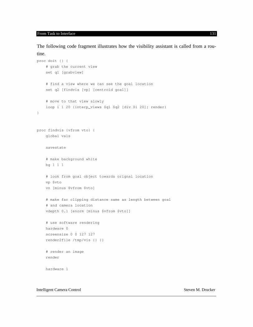
From Task to Interface 131
Intelligent Camera Control Steven M. Drucker
The following code fragment illustrates how the visibility assistant is called from a rou-
tine.
proc doit {} {
# grab the current view
set q1 [grabview]
# find a view where we can see the goal location
set q2 [findvis [vp] [centroid goal]]
# move to that view slowly
loop i 1 20 {interp_views $q1 $q2 [div $i 20]; render}
}
proc findvis {vfrom vto} {
global vals
savestate
# make background white
bg 1 1 1
# look from goal object towards orignal location
vp $vto
vn [minus $vfrom $vto]
# make far clipping distance same as length between goal
# and camera location
vdepth 0.1 [enorm [minus $vfrom $vto]]
# use software rendering
hardware 0
screensize 0 0 127 127
render2file /tmp/vis {} {}
# render an image
render
hardware 1
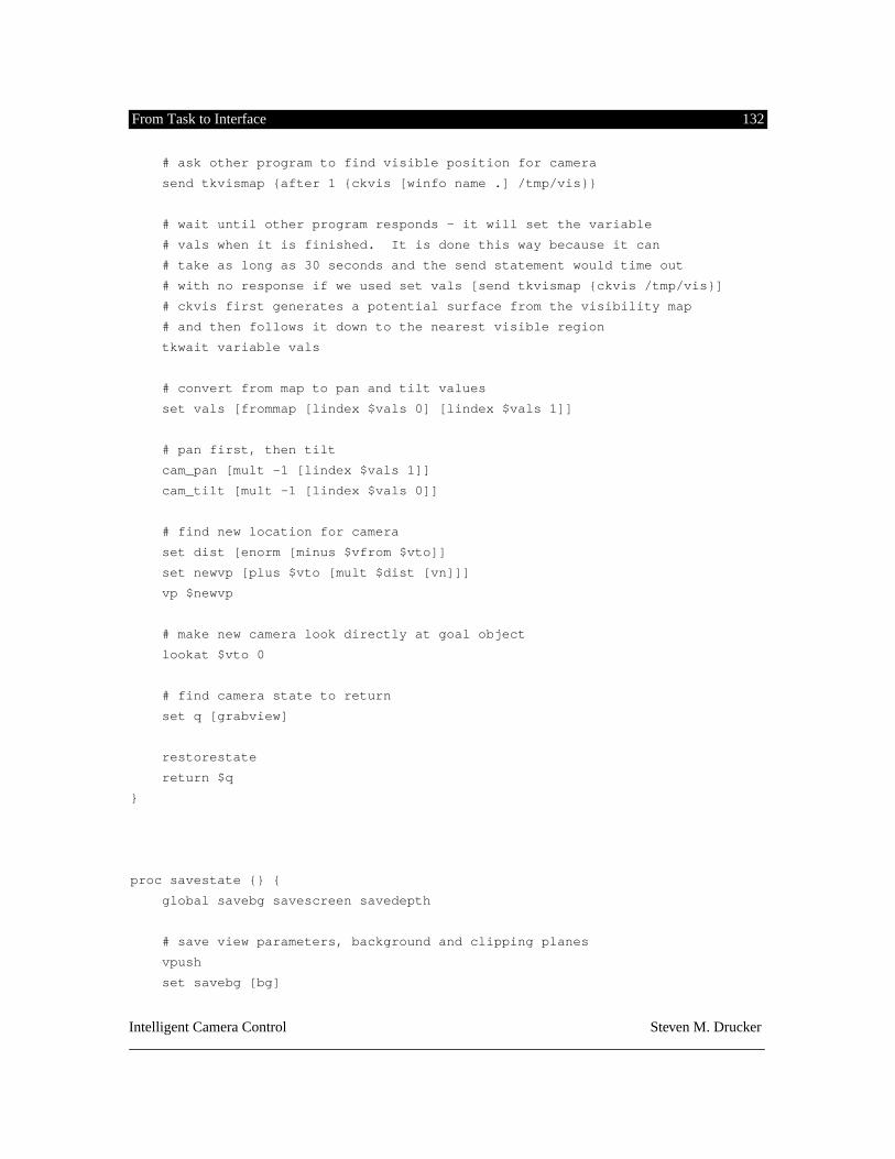
From Task to Interface 132
Intelligent Camera Control Steven M. Drucker
# ask other program to find visible position for camera
send tkvismap {after 1 {ckvis [winfo name .] /tmp/vis}}
# wait until other program responds - it will set the variable
# vals when it is finished. It is done this way because it can
# take as long as 30 seconds and the send statement would time out
# with no response if we used set vals [send tkvismap {ckvis /tmp/vis}]
# ckvis first generates a potential surface from the visibility map
# and then follows it down to the nearest visible region
tkwait variable vals
# convert from map to pan and tilt values
set vals [frommap [lindex $vals 0] [lindex $vals 1]]
# pan first, then tilt
cam_pan [mult -1 [lindex $vals 1]]
cam_tilt [mult -1 [lindex $vals 0]]
# find new location for camera
set dist [enorm [minus $vfrom $vto]]
set newvp [plus $vto [mult $dist [vn]]]
vp $newvp
# make new camera look directly at goal object
lookat $vto 0
# find camera state to return
set q [grabview]
restorestate
return $q
}
proc savestate {} {
global savebg savescreen savedepth
# save view parameters, background and clipping planes
vpush
set savebg [bg]
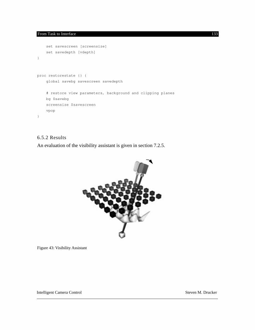
From Task to Interface 133
Intelligent Camera Control Steven M. Drucker
set savescreen [screensize]
set savedepth [vdepth]
}
proc restorestate {} {
global savebg savescreen savedepth
# restore view parameters, background and clipping planes
bg $savebg
screensize $savescreen
vpop
}
6.5.2 Results
An evaluation of the visibility assistant is given in section 7.2.5.
Figure 43: Visibility Assistant
Evaluations of Camera Control Interfaces 134
Intelligent Camera Control Steven M. Drucker
CHAPTER 7. EVALUATIONS OF CAMERA CONTROL INTERFACES
This chapter evaluates the effectiveness of the camera framework at several different lev-
els:
• Is the framework proposed useful across a sufficiently representative sam-pling of domains? Do the camera primitives assist the user in completingtasks in the examples?
• How convenient is it to place new interfaces on top of the framework?• How well do the camera primitives work? This can be looked at from a
computational point of view and a stylistic point of view.
7.1 Framework sufficiently representative:
The prototype applications that have been chosen have been selected to be from each of
the domains described in chapter 4. The virtual museum is an application primarily in the
exploratory domain and several different styles of interaction have been demonstrated for
different tasks. The conversation and virtual football game both represent tasks from the
planning domain. The primary difference between these two is based on the kind of inter-
face that has been constructed. In the conversation, a well defined, encapsulated agent with
different behaviors in response to different events has been constructed. In the football
game, a visual interface for combining and sequencing camera primitives has been demon-
strated, and a special purpose interface based on the requirements of real football directors
has been built. The mission planning system represents a task primarily from the rehearsal
domain. Different requirements, such as hands free operation, has necessitated another,
significantly different interface. Finally, the visibility demonstration represents one aspect
of the requirements of a control task.
In the following section each of the examples is examined in terms of the kind of assis-
Evaluations of Camera Control Interfaces 135
Intelligent Camera Control Steven M. Drucker
tance it has provided. Help for determining the quality of this assistance has been from
domain experts including Michael Sand (a museum designer), Eric Eisendratt (a sports
director for WBZ-TV), Glorianna Davenport (in her capacity as a documentary film
maker), and Professor Tom Sheridan (an expert in teleoperation and supervisory control).
Quotes have been included from these domain experts when appropriate.
7.2 Types of assistance:
In the introduction, a number of ways in which human reasoning and planning can run into
problems were described. This analysis will in part be devoted to seeing how those prob-
lems have been alleviated by the camera primitives that have been provided.To review,
that list is as follows (for a more complete description, see section 2.1.3 or [Norman92]):
1. Lack of completeness.2. Lack of precision.3. Inability to keep up with change.4. A heavy memory load.5. A heavy cognitive/computational load.
7.2.1 Types of assistance in the Virtual Museum
Lack of completeness
.
In any database related application, the system can contain knowledge represented in a
variety of formats which the user does not have access to. In its first and simplest form, the
Virtual Museum contains knowledge of all the pieces of art within the museum, where
they are located, and their ideal viewing position. Through a simple user request (currently
a listbox with a mouse selection though alternate means such as voice recognition might
be more appropriate in a totally immersive environment) the virtual camera can be trans-
ported instantly to a location and angle to view the selected artwork.
Associated operations can be performed on the basis of specific domain knowledge that
the computer contains for the museum.
Let me give you a rational of why I think your project is good. A very typical
Evaluations of Camera Control Interfaces 136
Intelligent Camera Control Steven M. Drucker
problem in a museum is for a visitor to come to a problem that they’re not con-versant with and understand what choices they have at this point; the menu prob-lem. Are there any specials today? What time of day is it? How long will thistake? A series of contextual things that the computer can be aware of but the usermight not be. If you could go to a lobby kiosk and describe yourself to the com-puter and say that I have a 5-year old with me and I also have my mother in lawwith me who has trouble walking and who doesn’t want to see breasts (she get’supset by nude paintings), and it’s my 3rd visit here and I haven’t been here in 8months, the computer can automatically regurgitate to you, using your rule set, anoptimal path since we’re only open for another hour and a half today; etc. Therule set could construct a tryptic for the visitor and a print out which gives you atimed intervalometer, saying spend 10 minutes here, 15 minutes here, and your 5year old will love this, and it has a set of decisions that the curators and you haveconspired on. For instance if you haven’t been here for 8 months, you must seethis new exhibit because everybody enjoys that. So you’ve immediately givensomeone a personalized tour that’s unique to them for the moment. It can gener-ate informed decisions based on your input, and even give you choices once it’scome up with options too, secondary and third level decisions [Sand94].
Lack of precision.
The virtual museum allows automatic placement at precisely the best point for viewing
certain objects in the museum (based on preselected opinions of the designer).
That would be useful in some of the walkthroughs that I’ve built for demonstra-tions to clients. You can click on a particular object, or set up a prefixed view thatis appropriate for that object. Kodak has this “stand here - use f-12 and take a pic-ture” located at all sorts of famous sights which allows tourist to create the per-fect take home shot [Sand94].
A heavy memory load.
The system can use internal memory to recall specific views that the user has saved or
even show different portions of the environment that have already been explored. Orienta-
tion, seems to be intimately related to memory, since remembering the movements made
before can sometimes be the only method of locating oneself in an environment. In the
Virtual Museum, orientation within the environment is provided for via a map-view which
contains the user’s location and direction of gaze within the museum.
Evaluations of Camera Control Interfaces 137
Intelligent Camera Control Steven M. Drucker
Giving you several ways to look at something is very important. Different peoplehave different predilections. Some people will love the plan view that you’ve gotthere. Other’s would find it very confusing, others might want an orthographicprojection, other people would just like the point of view. Other people mightwant an iconic view, like an MBTA map compared to a road map. You don’t haveto presume that one size fits all. The great thing about the computer is that youcan provide any one that the person wants. If the person wants words and a list,that’s fine [Sand94].
Inability to keep up with change.
The Virtual Museum is primarily a static domain so this is not a consideration in this appli-
cation.
A heavy computational/cognitive load.
In this case, overly repetitive situations, or situations where there are too many variables to
control can be greatly eased by the museum interface. When moving the virtual camera
through the museum, the user must constantly be specifying the desired position, orienta-
tion, and direction of movement within the museum. The interface provides a number of
ways to ease the repetitive, complex nature of the task. First, the motions of the user’s
mouse presses can be mapped in such a way to minimize the number of degrees of free-
dom being controlled. In this case, forwards or backwards on a virtual joystick constrains
the speed of the virtaul camera’s movement through the environment, right to left con-
strains the direction the view is turning (center implies no turn). The height of the virtual
camera is constrained to be the same height throughout control. While this limits the
degrees of freedom that are controlled to a manageable number, the user must still provide
continuous input. Alternate modes of control let the system take over movement of the
viewpoint to a calculated path to a specified goal location. The user can control the view
direction alone if desired or have the view direction point either straight ahead or at objects
of interest along the way. In addition, the system can make more use of internal knowledge
and calculate the best path from a particular location to another particular location, avoid-
ing obstacles within the environment and taking user requirements into account (for
instance, the user might want to avoid passage through certain areas - such as non-handi-
cap accessways). The virtual museum can assist in several other ways to shift the compu-
tational burden from the user to the computer. The system constrains the movements of the
Evaluations of Camera Control Interfaces 138
Intelligent Camera Control Steven M. Drucker
virtual camera from passing through walls. This prevents rapid changes in the image
which can be confusing to a user.
Does it find it’s own trajectory? You have some sort of rule set? That’s terrific!That would be very useful. Did you ever read the writings of Kevin Lynch. Hehas some good ideas about this in his “A View from the Road” book. He wroteone talking about the experience of driving. As you’re driving, you’re cognizantof the things that are going by, and we really take our sense of place from the con-glomeration, this gestalt of experiences and not just from the destination and heand I discussed ways in which you could come up with a new iconography thatwould be a new type of road sign, that would have to do with signs and combina-tions that were happening [Sand94].
7.2.2 Types of assistance in the Mission Planner System
Lack of completeness.
The mission planner contains physically based simulations of the behaviors of the aircraft
in the environment. The user does not need to be familiar with calculating the g-forces
based on banking the plane since the simulation can perform those actions for the user.
Lack of precision.
The mission planner can constrain the view exactly aligned with the axes of the plane
which may vary due to banking and other movements. The system can be used to look
from any object in the environment to any other object, and lines of sight can be easily and
precisely determined.
Inability to keep up with change.
Since the mission planner represents a dynamic environment, it is important that it assist
the user in tracking moving objects, or placing the viewpoint along moving objects look-
ing towards other objects. The user does not need to make any active effort to observe
changes in the environment.
A heavy memory load.
Sharp discontinuities between views make it difficult to understand the relationships
between objects within the environment. By constraining the pan rate of the virtual cam-
Evaluations of Camera Control Interfaces 139
Intelligent Camera Control Steven M. Drucker
era, the system can be used to help create and maintain a cognitive map of the mission
planning environment.
A heavy computational/cognitive load.
The system can map simple, high level voice commands from the user into actions for the
virtual camera in the environment. The user does not need to control individual degrees of
freedom of the camera at any time but can easily constrain the camera to move with or to
follow objects in the environment.
7.2.3 Types of assistance for Conversation Agent
The conversation agent shows potential in many areas. It is a first stab at encoding cine-
matic rules into a high level language that can be used in a variety of different situations. It
is a reactive system which can change its response based on changes within the environ-
ment. It can also relieve the user from the burden of low level control of the camera.
Lack of completeness.
One of the most interesting possibilities enabled by camera primitives is the ability to cre-
ate a high level language which incorporates cinematic rules. The rudiments of this lan-
guage have been demonstrated by being able to perform a medium shot, or an over-the-
shoulder shot, but much more work can be done. The system can aid those that know at a
high level what they want, but don’t want to know the details of controlling a virtual cam-
era in a graphical environment. Or the system can offer a first pass suggestion to how a
shot should be framed. The user can then choose this shot or alternate shots to help previ-
sualize how a sequence should be shot.
Lack of precision.
The ability of the system to find the camera position based on framing specifications is
particularly exciting. This was one of the biggest problems with previous systems that
have been used including the CINEMA system. It was always difficult to find an appropri-
ate position for the camera. It’s also exciting that there’s a precise level of control related
to what’s in the frame as opposed to just where the camera is in space. That’s much more
accessable to an actual moviemaker.
Evaluations of Camera Control Interfaces 140
Intelligent Camera Control Steven M. Drucker
Inability to keep up with change.
Another exciting potential of the system is its ability to respond to a changing environ-
ment. As the characters are moving about the system might eventually be able to make
choices on how to film the situation based on stylistic rules and higher level knowledge of
the narrative structure in the situation. For instance, if one character stands up in a scene, it
may be appropriate to follow him by panning and tilting, or it could be qualitatively differ-
ent to follow him by moving the entire base of the camera around. A complete system
must incorporate both audio and plot elements in order to continue research on a flexible,
reactive agent.
A heavy memory load.
The system can help maintain continuity from shot to shot. It can automatically ensure that
certain objects are in view across cuts and it can maintain framing conventions across edit
boundaries. Even more significantly, once a higher level language is developed which
includes cinematic style, continuity of style throughout entire sequences could be main-
tained.
A heavy cognitive/computational load.
The system can first ease the cognitive load of understanding the environment by allowing
the user to recover the positions of objects and the camera in relation to each other. It can
also, as previously discussed, take the high level framing specification and find a position
for the camera that satisfies the diretor’s goals. When a director is not satisfied with a shot,
the system might be able to offer alternate possibilities placing different emphasis on the
director’s goals.
7.2.4 Types of assistance for Virtual Football Game
The virtual football game system can assist in the following ways.
Lack of completeness.
By providing the system with the knowledge of what type of play might be transpiring, the
system can choose a style of viewing that might be most appropriate. The system can act
Evaluations of Camera Control Interfaces 141
Intelligent Camera Control Steven M. Drucker
as a kind of expert system for filming football games.
When we’re out there filming a game, the director quickly gives rough instruc-tions to all the cameramen and they know just what to do. They can tell in the firstmoments of the play whether it will be a passing play or a running play and theyknow how to cover each play [Eisendratt94].
Lack of precision.
In shooting a real football game, one of the biggest problems is for the camera man to
respond quickly enough to movements of the ball in order to track it accurately. Given
absolute knowledge about the position of the ball, the virtual football game can always
track the ball precisely.
When a play is taking place, we never cut from one camera’s view to anotherbecause it might be confusing and because we might miss some action. The cam-eramen are doing their best to keep the ball in view at any moment and they oftendon’t have much time for anything else than that. It would be great if we couldautomate some of that in filming a real football game like you’ve done in the vir-tual football game. It really might bring about whole new possibilities for cover-ing a game [Eisendratt94].
Inability to keep up with change.
The user can specify certain objects that are to be tracked and let the system perform the
rest. Furthermore, certain conditions can be specified, for instance, keep two certain char-
acters in view at the same time and the system will maintain those conditions.
This goes back to the lack of precision issue. If we can automatically follow anyplayer and the ball in real life, that would help our jobs a great deal. The onlything is then is that you’d want to have more cameras to cover more possibilities.I’d like a camera to catch the reaction shot of the coach while a play is happeningand not have to sacrifice any of the cameras that I’m using to cover the play. Inreally high-budget games like a SuperBowl, you’ve got all the cameras you need,but in other games you’ve only got the 5 or 6 cameras set up in the way you haveit set up in the virtual football game [Eisendratt94].
Heavy cognitive/computational load:
Many situations in filming the a football game repeat over and over. By encapsulating a set
of rules into a camera module, the modules can be used over and over with small varia-
tions due to stylistic preferences. Also, currently, filming a football game usually takes at
Evaluations of Camera Control Interfaces 142
Intelligent Camera Control Steven M. Drucker
least one director, and at least 6 camera people each who has a specific job during filming
the play. By being able to automate both the choice of jobs and the actual filming itself, the
system could greatly ease the computational load for a director, and the director could con-
centrate more on the style of the presentations.
It does start to get to be a kind of repetitive task filming a game. But the interest-ing stuff is when things go wrong with a play, or catching the reactions of playerswhen special things happen. I don’t think you could automate that, though youcertainly could automate some of the rest like following the play as you’ve doneand catch some of the other things by hand [Eisendratt94].
7.2.5 Types of assistance for Visibility Assistant
Lack of completeness.
The visibility assistant can keep track of the positions of all the objects in the environment
and even if the user does not know a particular position of an object, the assistant can be
used to find a view where that object is visible.
I think it would be interesting if you used the system to help keep track of viewsof people besides just views of objects. This could be related to some work that isbeing done in Computer Supported Cooperative Work. People could direct thecamera by “pulling” the camera to face them, or show other people views ofthings by “pushing” the camera to a certain point of view. It would be especiallyinteresting if you could somehow find the camera constraints that might supportthis kind of behavior.[Sheridan94].
Lack of precision.
The change of view can be made so that the camera moves the minimum amount in order
to place the object in view.
Inability to keep up with change.
The system can automatically keep track of the movements of all objects in the environ-
ment including both occluding objects and the goal visible object. The viewpoint can be
changed constantly to keep the object in view or only on user request (since constant
changes of the view might be disorienting for the viewer).
A heavy cognitive/computational load.
Evaluations of Camera Control Interfaces 143
Intelligent Camera Control Steven M. Drucker
The computational burden of tracking an object and making sure it is visible has been
removed from the user and transferred to the intelligent camera interface.
It’s very important that the user has some level of choice when the systemchooses views. Motion parallax is an extremely useful set of depth cues and wefound that in experiments, users really needed that to perform better. In additionto a visibility constraint, Harry Das did some experiments for automatic viewselection for controlling a telemanipulator. He tried a view that tried to maximizethe angle between the camera and the lines which connected the end-effector andthe goal and obstacle objects. It seems that you could do that fairly easily in thecontext of your framework[Sheridan94].
7.3 Convenience of the framework
The convenience of the framework still remains to be proven. Although the framework has
been used in a number of diverse applications, I have been the only programmer to use it
so far. Several projects where others will incorporate the framework for controlling the
camera. One researcher will use the framework to design a cinematic previsualization sys-
tem. Another researcher will use the framework as the basis to control the camera in an
interactive, immersive, narrative environment.
7.4 How well do the camera primitives work?
This question can be addressed in three different ways. First, do the primitives achieve the
desired goals of the user. Second, how efficient is the framework for achieving those goals.
And third, does the output of the primitives look right stylistically to the user, and is the
output sufficiently customizable to give the user of the system sufficient stylistic control
over the final output.
One of the problems of trying to thoroughly examine the effectiveness of the primitives
are that they can be combined in an infinite number of ways. It is impossible to check to
see if all the combinations do eventually converge to the desired results. One basic prob-
lem in all systems based on constrained optimization is how the system deals with local
minima.
7.4.1 Local Minima
Evaluations of Camera Control Interfaces 144
Intelligent Camera Control Steven M. Drucker
Several methods have been developed to alleviate the problem of the camera settling into a
locally optimal solution which is not necessarily an appropriate solution. Sometimes this
situation is not a problem at all but a desired result since local optimums may be sufficient.
The first method of dealing with local minima is to explicitly design the algorithm to gen-
erate a constraint surface that does not contain any local minima. This is the method used
for one type of path planning and the visibility algorithm. In both these methods, a dis-
tance function from a goal location was generated by propagating a wave away from the
goal. The wave moves around all the obstacles in the environment and thus guarantees that
the goal location will be the only minimum in the system. However if more than one con-
straint is combined, this condition can no longer be guaranteed.
Another method of escaping from local minima was explored in the context of path plan-
ning by discretizing the space and using a breadth first search of the gradient of the sur-
face. Thus the system is guided by optimization but if it settles in a local minimum that is
known not to be the goal, the system can search further and further away from the local
minimum, until a new minimum direction is found.
Yet another method of overcoming local minima is to use external knowledge to guide the
initial location for starting the minimization. This was used for some of the simple projec-
tive camera constraints such as the over the shoulder shot. If the user starts the minimiza-
tion with the camera located somewhere on the line (but not between) that connects the
two objects that are the goals of the primitive, the system usually does not get trapped in
local minima.
Finally, a last method that can be used is to restart the minimization process from a variety
of locations in the environment and to eventually use the lowest minimum. This is similar
to the method of simulated annealing and has been extremely successful at solving a num-
ber of nearly intractable problems. On a sufficiently fast system, perhaps a massively par-
allel one, this might be an extremely robust way of dealing with local minima.
Somewhat surprisingly, in the five systems demonstrated, local minima were rarely a prob-
Evaluations of Camera Control Interfaces 145
Intelligent Camera Control Steven M. Drucker
lem for the constraint solver. Local path planning (appendix 1.3 – non-wave propagation)
was the constraint most prone to local minima. Occasionally, some projective constraints
would also be trapped in local minima when the solution was started at a completely arbi-
trary position. A “nudge” from the user usally alleviated the problem. Sometimes, it was
better to formulate the problem for certain constraints as “hard” constraints, and then later
relax the requirement and incorporate them as “soft” constraints once a better initial condi-
tion was found for the optimization.
7.4.2 Efficiency
The efficiency of the constraint framework does of course depend upon the number and
type of constraints and optimization functions being attempted. Currently, the system can
usually solve a problem containing 3 non-linear optimization functions and 9 nonlinear
inequality constraints in approximately one tenth of a second on an IRIS Indigo system.
The algorithms for path planning and visibility determination involve extensive calcula-
tions for determining the constraint surface before optimization. However, once these sur-
faces are calculated, the solution is extremely rapid. The visibility calculation for a typical
scene takes less than 4 seconds on an IRIS Indigo system. Currently, the system is using
the built in software rendering to generate the visibility map and the speed of this part of
the algorithm could be sped up considerably by using the hardware renderer of the work-
station. However, the most time consuming part of the algorithm is propagating the dis-
tance wave from the visible regions. This algorithm is readily amenable to parallelization
which could bring about significant speed enhancements. In the path planning algorithm,
most of the constraint surfaces can be precalculated so that the paths can be found in milli-
seconds on an IRIS Indigo system. The precalculation can take up to thirty seconds
depending upon the number of nearest neighbors used for expanding the wavefront.
A thorough algorithmic analysis for the CFSQP is provided in [Lawrence94] and is not
discussed in this thesis.
7.4.3 Stylistic Expressiveness
This is the most difficult quality to assess, but many attempts have been made to make
Evaluations of Camera Control Interfaces 146
Intelligent Camera Control Steven M. Drucker
some of the primitives both stylistically flexible and for their output to look correct. To a
certain extent, this is discussed in section 7.2.3.
In the pathplanning primitive, there are a number of parameters that can be controlled
including the closest distance that the camera may be to an object as it passes. Also, the
number of directions that the camera can move from any discretized location on the con-
straint surface has been examined along with the affects on the resultant paths. One key
point of the path planning primitive is that it treats the position of the camera separately
from its orientation. While this makes the computation and search of the potential function
possible, it may lead to the somewhat inhuman behavior of the planned path. By using
multi-resolution optimization methods, it might be possible to plan a path that also con-
tains optimization conditions on the orientation of the camera during planning. Another
noticeable problem with the path planning constraint is the way in which it travels through
doorways. Since the distances function that is propagated out from the doorway moves
equally in all directions, the camera will often approach the doorway at an oblique angle
which is extremely disconcerting. This can be overcome by changing the way the distance
function propagates from the doorway, or by adding constraints to the interpolating spline.
Finally, the path planning does not constrain the velocity of the camera at all, so that the
speed of movement along the spline is now determined completely independently. Further
constraints might be appropriate to allow easing in and out of movement or slower move-
ments at points of interest.
The visibility constraint currently moves to the nearest visible area, but that area might be
extremely small. A way of balancing the nearest area with the largest area might be useful
stylistically.
Some of the other camera primitives might be used as a basis for forming a high level lan-
guage for stylistic expression. This could enforce stylistic consistency across sequences.
For instance, if a situation is tense, a constraint could be added that prevents the camera
from ever being more than a certain distance from an object or that the projection of all
objects of interest be a certain size or greater. Or if low angles are preferable for a situa-
tion, then the camera’s position can be constrained to always be from below a certain level.

Evaluations of Camera Control Interfaces 147
Intelligent Camera Control Steven M. Drucker
There is no inherent style in these primitives themselves, but only in the ways that they can
be combined.
Conclusions and Future Work 148
Intelligent Camera Control Steven M. Drucker
CHAPTER 8. CONCLUSIONS AND FUTURE WORK
8.1 Conclusions
This thesis has taken a systematic approach to the problem of controlling a virtual camera
within a graphical environment. The first step involved generating a classification of dif-
ferent interactive graphical domains. This taxonomy has been used to derive the visual
tasks that are required in each domain. The taxonomy may be useful for deriving other,
non-visual tasks, for instance if someone wishes to explore mechanisms for end-user pro-
gramming in interactive graphical environments, it would be necessary to provide meth-
ods for each of the domains described in the taxonomy.
In addition to the taxonomy, pertinent methods and techniques have been examined from
the areas of cinematography, human factors, teleoperation, and robotics to help define
camera primitives for accomplishing visual tasks. Particularly novel are
projection camera
primitves that help define the position of the camera based on a desired configuration of
the resulting image (see section 5.11.3).
A framework based on constrained optimization for combining and reusing camera primi-
tives has been proposed and constructed. Primitives can be encoded as constraints and can
be combined in a number of different fashions ranging from hard constraints, where a
solution is incorrect if the constraint is not met, to soft constraints where the system tries to
balance among a number of conflicting constraints.
On top of the framework a number of different example applications have been built. The
examples demonstrate not only many different styles of interfaces, but were selected as a
Conclusions and Future Work 149
Intelligent Camera Control Steven M. Drucker
representative sampling of the domains described in the taxonomy.
The virtual museum represents the exploratory domain. The virtual museum tied widgets
and mouse clicks to the activation of different modules constructed from the camera prim-
itives. The mission planner is an example from the rehearsal domain. The mission planner
uses an immersive environment and high level commands with a voice recognition sys-
tem. The conversation filming agent represents an application in the planning domain.
Camera primitives are encapsulated into the behaviors of a reactive agent which can auto-
matically incorporate rules for presenting the scene to an external observer. The virtual
football game is also an application in the planning domain. A visual programming lan-
guage has been developed to easily combine and sequence camera primitives. The visibil-
ity assistant is an example of an application in the control domain. The camera responds to
changes in the environment to keep an object constantly in view allowing the user to per-
form a task effectively. The examples were evaluated by consulting domain experts in
each of the areas and by identifying the ways in which the camera could assist the user in
perfoming tasks within each application.
8.2 Future Work
A good thesis is not an end but a beginning. There are many things that can be done to
extend this work, both to improve it and to push it in new directions.
8.3 Improving current work
Using TCL as a prototyping language for the development and testing of new camera
primitives made it possible to try out many different ways of encoding and combining
primitives. However when the same routines were re-coded in C, the performance was
more than two orders of magnitude faster. An automatic way to compile TCL-code, or a
more efficient interpreter such as an embeddable Scheme would be a welcome addition to
the the extended 3d system.
Nearly all the camera primitives have relied on the constraint solver’s built in ability to
find gradiants through forward differencing. By including a method to evaluate derivatives
Conclusions and Future Work 150
Intelligent Camera Control Steven M. Drucker
symbolically such as those suggested in [Gleicher92], [Cohen92], or [Kass92], the system
could be made more robust and more efficient.
Higher dimensional manifolds would be interesting to explore, especially for the path
planning and visibility constraints. For more dimensions than three, multi-resolution opti-
mization techniques would probably be needed. The path planning and visibility con-
straints lend themselves to parallel computation and this would be an interesting avenue of
research. Path planning through a dynamic environment is still a very difficult problem
and research in that direction would be also be interesting.
8.4 Extending the current work
This thesis has shown that camera primitives can form the basis for the behaviors of soft-
ware agents. More sophisticated agents that can actively decide among a number of built
in behaviors, or perhaps to combine primitives into new behaviors on the fly present excit-
ing possibilities. The software agents can be designed to automatically present information
in a coherent fashion or be used within interactive environments to guide the way the
scene is depicted. Multiple agents with different goals and perceptions can each show a
different representation of the graphical environment to different observers.
Whether the camera primitives are embedded in software agents, or combined and
sequenced explicitly, a higher level, cinematic language needs to be developed. The proper
language could permit an ease of interaction with graphical environments that does not
exist today. Stylistic expression in cinematography has just been touched on in this thesis.
It would be interesting to attempt to quantify an analysis of cinematic style and attempt to
incorporate that analysis into a software agent. The camera primitives discussed in this
thesis are a basis for the actions of the agent, but not for the reasoning.
The convenience of the framework is still somewhat unproven. It needs to be used as the
basis for many different user interfaces. The process of building an interface takes several
iterations of design and user testing. It would be desirable to build a number of interfaces
for tasks ranging from cinematic pre-visualization to automatic filming for interactive nar-
rative environments.
Path Planning 151
Intelligent Camera Control Steven M. Drucker
APPENDIX 1: PATH PLANNING
The following chapter describes the algorithms for pathplanning used in this thesis.
The problem of finding a collision free path through a complicated environment has been
examined a great deal in the context of robot motion planning. There have been several
attempts at incorporating pathplanning systems into a graphical environment, or using the
special capabilities of graphics hardware to assist in path planning [Lengyel91]. In gen-
eral, the problem can be thought of as either vector-based approaches or bitmap
approaches, somewhat akin to hidden surface removal in computer graphics. The vector
based approaches involve decomposing the problem into an equivalent graph searching
problem by constructing visibility graphs or connected regions [Lozano-Perez80,
Brooks83]. The bitmap approaches involve discretizing space into regular occupied or free
cells and traveling through bitmap from one adjacent cell to the next [Lengyel91,
Barraquand89, Latombe91].
Schröder and Zeltzer implemented an algorithm introduced by Lozano-Perez [Lozano-
Perez80] in a virtual environment system called BOLIO [Schröder88, Zeltzer89]. A visi-
bility graph was constructed based on the projection of all the objects in the environment
onto the floor plane. The actor’s position and the destination position were then connected
to the visibility graph and the A* algorithm was run to search the visibility graph. The
entire algorithm needed to be rerun whenever an object was moved. The visibility graph
method tends to produce paths that graze objects as closely as possible as well as paths
with straight lines connected to other straight lines which may be an unnatural way to
move a camera. The algorithm also does not take advantage of the graphics hardware
capabilities present in a graphics workstation. The path planning scheme described in this
Path Planning 152
Intelligent Camera Control Steven M. Drucker
paper uses a room-to-room visibility graph to first determine the overall path for the cam-
era, but then uses other more appropriate techniques for negotiating each room.
The local path planning technique used here is somewhat based on [Latombe90] in which
the scene is rendered from an overhead view and a bitmap is constructed with each pixel
representing either free space or an obstacle. This bitmap was then turned into a configura-
tion space by growing each obstacle region by the size of the moving object for several
different orientations. In our system, we assume a spherical size for the camera so the con-
figuration space does not need to be concerned with rotation. A numerical function was
propagated through the bitmap from a destination location to the current location and an
appropriate path through the configuration space was found by following the downward
gradient of the numerical function. Their goal was not for camera motion planning or even
for graphics animations, but to use a graphic workstation to assist in robot motion plan-
ning. Their paths were not necessarily suitable for camera movements due to the distance
metric which they chose to propagate through the configurations space. They propagated
the numerical function only until it reached a given starting point. In contrast, our algo-
rithm is designed to be used in a building environment, precomputing as much as possible,
and is specifically tailored to controlling a camera in a natural fashion.
The pathplanning process is decomposed into several sub-algorithms, many of which can
be precomputed in order to speed calculation as much as possible. First, a general descrip-
tion of the overall process is given, then more detailed descriptions of each sub-algorithm
follow.
The problem of traveling from one point in the museum to another point is first decom-
posed into finding which doors to travel through. A node to node connectivity graph is pre-
computed based on the accessibility between adjacent rooms in the environment. Accessi-
bility can either be indicated by hand, or by an automatic process which uses a rendered
image of the building floor, clipped at door level, and a simple visibility test between
points on either side of a door. This visibility graph can be updated based on special acces-
sibility requirements (such as handicapped access between rooms).
Path Planning 153
Intelligent Camera Control Steven M. Drucker
Traversing the graph is done by a well known graph searching technique called A*
[Hart68]. The A* process, discussed in section 1.1, produces a list of “straight-line” node-
node paths. Paths then need to be computed between each node to avoid obstacles within
each room.
The process of finding the path from a doorway to any point within a room, or finding the
path from any point in the room to the doorway is discussed in section 1.2. This algorithm
is optimized for finding paths that originate or terminate at a doorway, so another algo-
rithm must be used to navigate from one point to another point within a room. This second
algorithm, described in section 1.3, can also deal with a partially dynamic environment as
opposed to the strictly static environment discussed in the first algorithm. Finally, a
method for generating a guided tour through the environment is discussed in the last part
of section 1.4.
A1.1 A*
The A* algorithm is based on [Hart68]. It is guaranteed to return a path of minimum cost
whenever that path exists and to indicate failure when that path does not exist.
As discussed in Robot Motion Planning [Latombe91], the A* algorithm iteratively
explores the node-graph by following paths that originate at a particular node. At the
beginning of each iteration, there are some nodes that have already been visited, and some
that are as yet unvisited. For each node that has already been visited, only the path with
minimum cost to that node is memorized. Eventually the destination node is reached (if
that node is reachable), and the minimum cost path can be reconstructed. Since the A* is
such a common algorithm, readers are referred either to [Hart68] or [Latombe91] for a
description of the implementation.
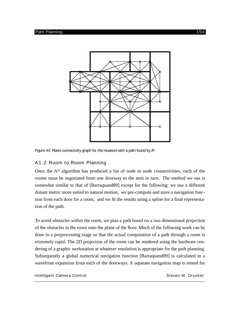
Path Planning 154
Intelligent Camera Control Steven M. Drucker
Figure 44: Room connectivity graph for the museum with a path found by A*
A1.2 Room to Room Planning
Once the A* algorithm has produced a list of node to node connectivities, each of the
rooms must be negotiated from one doorway to the next in turn. The method we use is
somewhat similar to that of [Barraquand89] except for the following: we use a different
distant metric more suited to natural motion, we pre-compute and store a navigation func-
tion from each door for a room, and we fit the results using a spline for a final representa-
tion of the path.
To avoid obstacles within the room, we plan a path based on a two dimensional projection
of the obstacles in the room onto the plane of the floor. Much of the following work can be
done in a preprocessing stage so that the actual computation of a path through a room is
extremely rapid. The 2D projection of the room can be rendered using the hardware ren-
dering of a graphic workstation at whatever resolution is appropriate for the path planning.
Subsequently a global numerical navigation function [Barraquand89] is calculated in a
wavefront expansion from each of the doorways. A separate navigation map is stored for
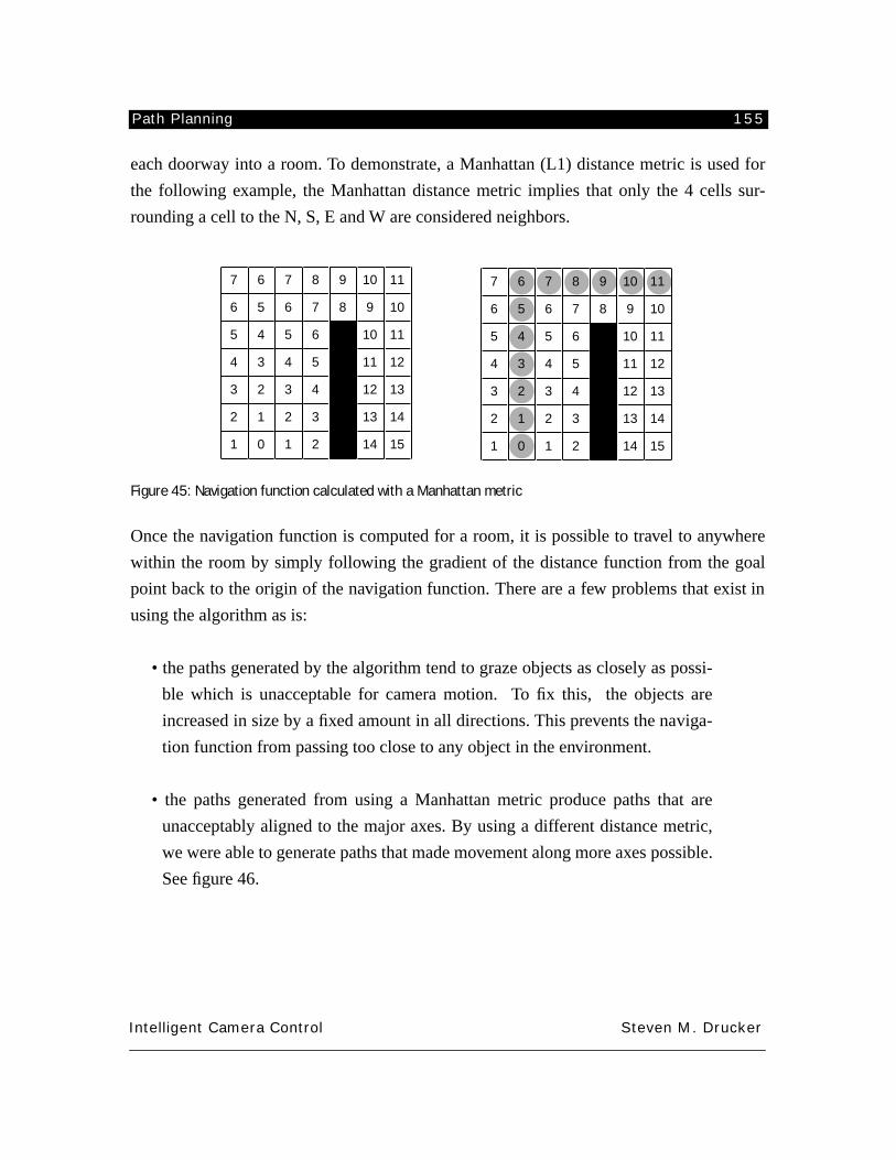
Path Planning 155
Intelligent Camera Control Steven M. Drucker
each doorway into a room. To demonstrate, a Manhattan (L1) distance metric is used for
the following example, the Manhattan distance metric implies that only the 4 cells sur-
rounding a cell to the N, S, E and W are considered neighbors.
Figure 45: Navigation function calculated with a Manhattan metric
Once the navigation function is computed for a room, it is possible to travel to anywhere
within the room by simply following the gradient of the distance function from the goal
point back to the origin of the navigation function. There are a few problems that exist in
using the algorithm as is:
• the paths generated by the algorithm tend to graze objects as closely as possi-
ble which is unacceptable for camera motion. To fix this, the objects are
increased in size by a fixed amount in all directions. This prevents the naviga-
tion function from passing too close to any object in the environment.
• the paths generated from using a Manhattan metric produce paths that are
unacceptably aligned to the major axes. By using a different distance metric,
we were able to generate paths that made movement along more axes possible.
See figure 46.
7
6
5
4
3
2
1
6
5
4
3
2
1
0
7
6
5
4
3
2
1
8
7
6
5
4
3
2
9
8
0
0
0
0
0
10
9
10
11
12
13
14
11
10
11
12
13
14
15
7
6
5
4
3
2
1
6
5
4
3
2
1
0
7
6
5
4
3
2
1
8
7
6
5
4
3
2
9
8
0
0
0
0
0
10
9
10
11
12
13
14
11
10
11
12
13
14
15
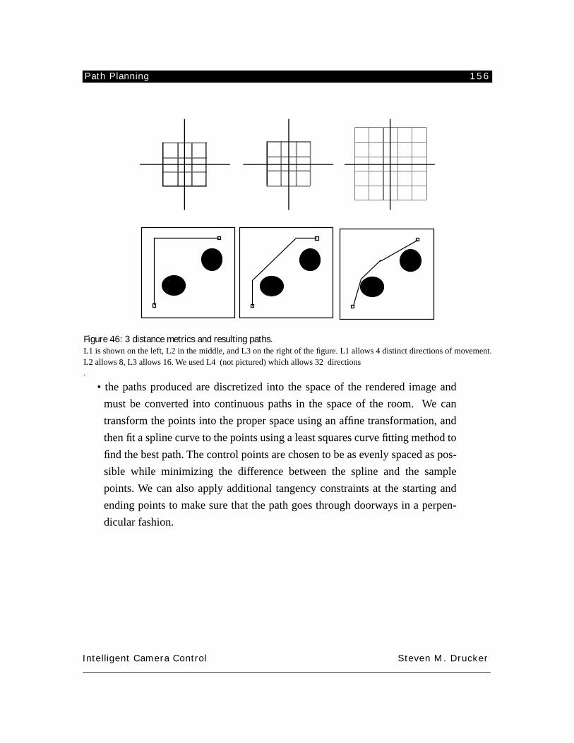
Path Planning 156
Intelligent Camera Control Steven M. Drucker
Figure 46: 3 distance metrics and resulting paths.
L1 is shown on the left, L2 in the middle, and L3 on the right of the figure. L1 allows 4 distinct directions of movement.L2 allows 8, L3 allows 16. We used L4 (not pictured) which allows 32 directions.
• the paths produced are discretized into the space of the rendered image and
must be converted into continuous paths in the space of the room. We can
transform the points into the proper space using an affine transformation, and
then fit a spline curve to the points using a least squares curve fitting method to
find the best path. The control points are chosen to be as evenly spaced as pos-
sible while minimizing the difference between the spline and the sample
points. We can also apply additional tangency constraints at the starting and
ending points to make sure that the path goes through doorways in a perpen-
dicular fashion.
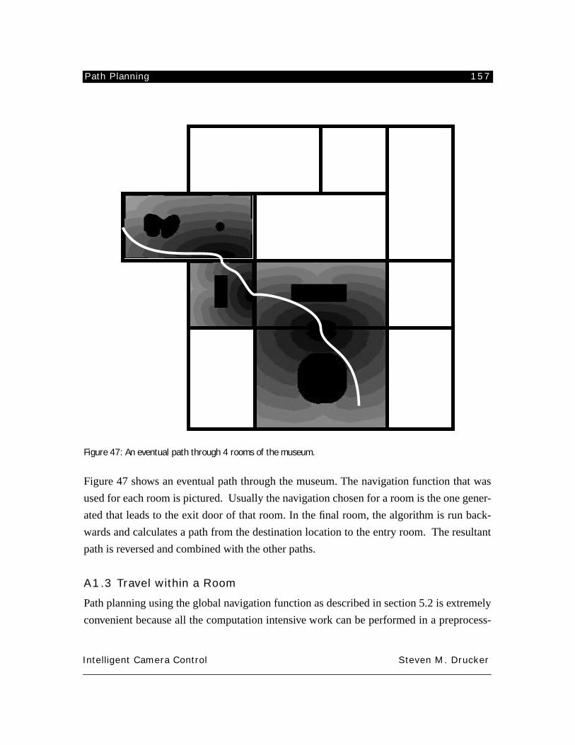
Path Planning 157
Intelligent Camera Control Steven M. Drucker
Figure 47: An eventual path through 4 rooms of the museum.
Figure 47 shows an eventual path through the museum. The navigation function that was
used for each room is pictured. Usually the navigation chosen for a room is the one gener-
ated that leads to the exit door of that room. In the final room, the algorithm is run back-
wards and calculates a path from the destination location to the entry room. The resultant
path is reversed and combined with the other paths.
A1.3 Travel within a Room
Path planning using the global navigation function as described in section 5.2 is extremely
convenient because all the computation intensive work can be performed in a preprocess-
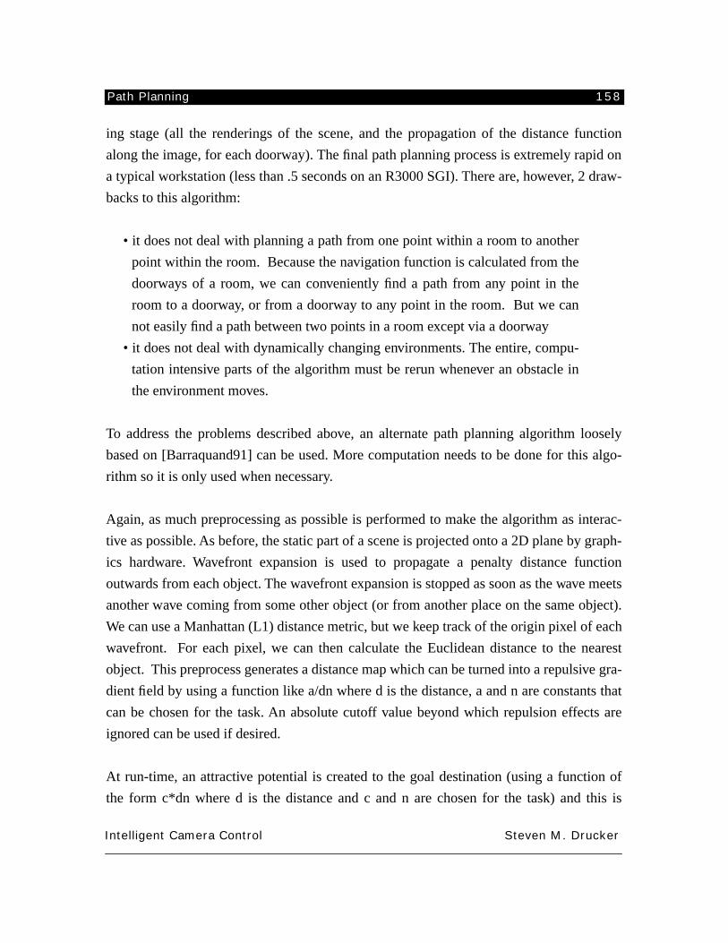
Path Planning 158
Intelligent Camera Control Steven M. Drucker
ing stage (all the renderings of the scene, and the propagation of the distance function
along the image, for each doorway). The final path planning process is extremely rapid on
a typical workstation (less than .5 seconds on an R3000 SGI). There are, however, 2 draw-
backs to this algorithm:
• it does not deal with planning a path from one point within a room to another
point within the room. Because the navigation function is calculated from the
doorways of a room, we can conveniently find a path from any point in the
room to a doorway, or from a doorway to any point in the room. But we can
not easily find a path between two points in a room except via a doorway
• it does not deal with dynamically changing environments. The entire, compu-
tation intensive parts of the algorithm must be rerun whenever an obstacle in
the environment moves.
To address the problems described above, an alternate path planning algorithm loosely
based on [Barraquand91] can be used. More computation needs to be done for this algo-
rithm so it is only used when necessary.
Again, as much preprocessing as possible is performed to make the algorithm as interac-
tive as possible. As before, the static part of a scene is projected onto a 2D plane by graph-
ics hardware. Wavefront expansion is used to propagate a penalty distance function
outwards from each object. The wavefront expansion is stopped as soon as the wave meets
another wave coming from some other object (or from another place on the same object).
We can use a Manhattan (L1) distance metric, but we keep track of the origin pixel of each
wavefront. For each pixel, we can then calculate the Euclidean distance to the nearest
object. This preprocess generates a distance map which can be turned into a repulsive gra-
dient field by using a function like a/dn where d is the distance, a and n are constants that
can be chosen for the task. An absolute cutoff value beyond which repulsion effects are
ignored can be used if desired.
At run-time, an attractive potential is created to the goal destination (using a function of
the form c*dn where d is the distance and c and n are chosen for the task) and this is
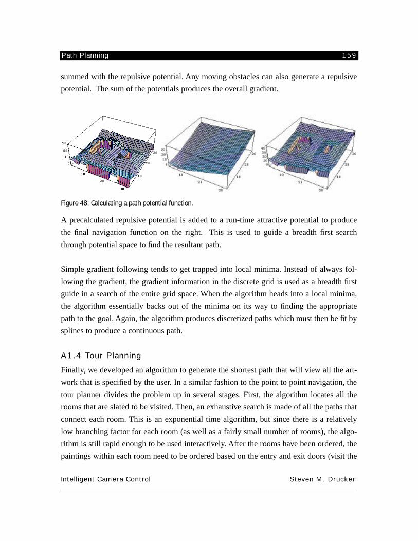
Path Planning 159
Intelligent Camera Control Steven M. Drucker
summed with the repulsive potential. Any moving obstacles can also generate a repulsive
potential. The sum of the potentials produces the overall gradient.
Figure 48: Calculating a path potential function.
A precalculated repulsive potential is added to a run-time attractive potential to produce
the final navigation function on the right. This is used to guide a breadth first search
through potential space to find the resultant path.
Simple gradient following tends to get trapped into local minima. Instead of always fol-
lowing the gradient, the gradient information in the discrete grid is used as a breadth first
guide in a search of the entire grid space. When the algorithm heads into a local minima,
the algorithm essentially backs out of the minima on its way to finding the appropriate
path to the goal. Again, the algorithm produces discretized paths which must then be fit by
splines to produce a continuous path.
A1.4 Tour Planning
Finally, we developed an algorithm to generate the shortest path that will view all the art-
work that is specified by the user. In a similar fashion to the point to point navigation, the
tour planner divides the problem up in several stages. First, the algorithm locates all the
rooms that are slated to be visited. Then, an exhaustive search is made of all the paths that
connect each room. This is an exponential time algorithm, but since there is a relatively
low branching factor for each room (as well as a fairly small number of rooms), the algo-
rithm is still rapid enough to be used interactively. After the rooms have been ordered, the
paintings within each room need to be ordered based on the entry and exit doors (visit the
Path Planning 160
Intelligent Camera Control Steven M. Drucker
painting first which is closest to the door from which the room is entered, and visit the
painting last next to the exit door). At this point we have a list of paintings that will be vis-
ited in the order specified. The algorithms discussed in the previous three sections can be
used to plan paths between each of the paintings and the results can be combined into the
global tour.
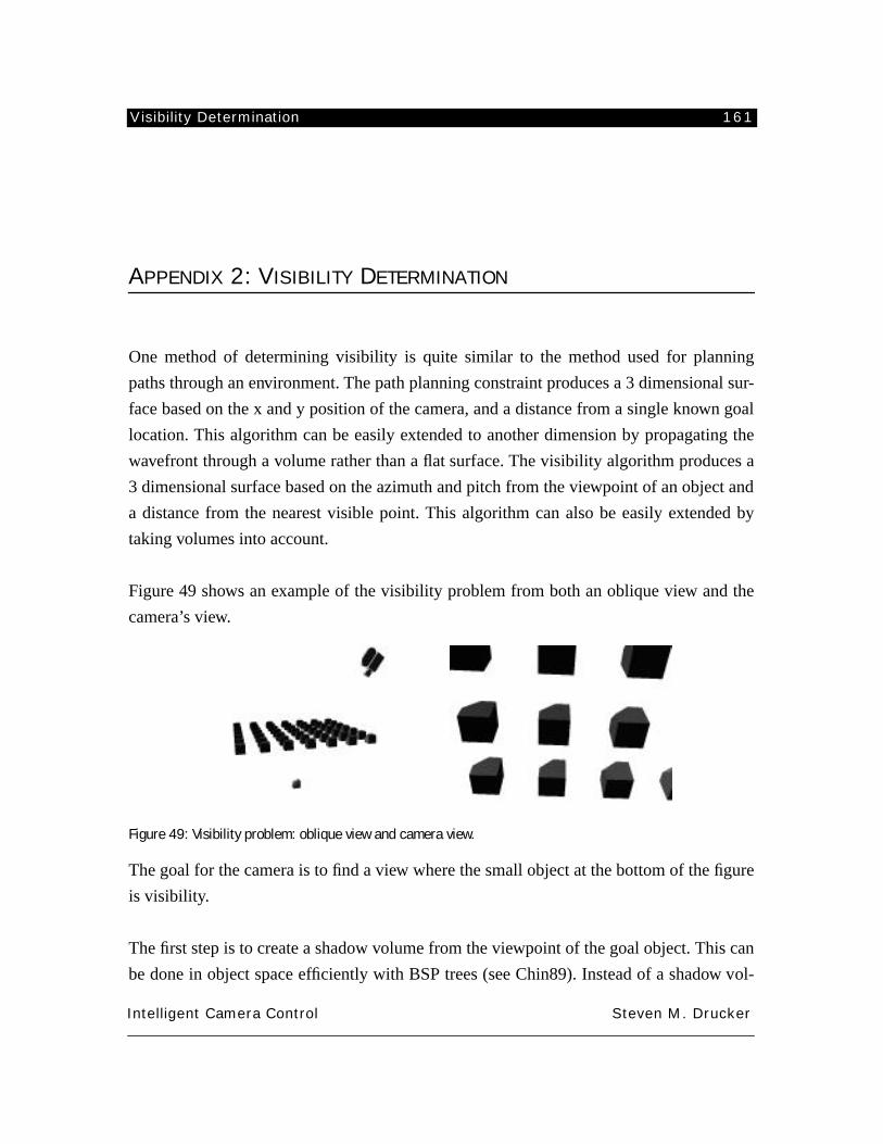
Visibility Determination 161
Intelligent Camera Control Steven M. Drucker
APPENDIX 2: VISIBILITY DETERMINATION
One method of determining visibility is quite similar to the method used for planning
paths through an environment. The path planning constraint produces a 3 dimensional sur-
face based on the x and y position of the camera, and a distance from a single known goal
location. This algorithm can be easily extended to another dimension by propagating the
wavefront through a volume rather than a flat surface. The visibility algorithm produces a
3 dimensional surface based on the azimuth and pitch from the viewpoint of an object and
a distance from the nearest visible point. This algorithm can also be easily extended by
taking volumes into account.
Figure 49 shows an example of the visibility problem from both an oblique view and the
camera’s view.
Figure 49: Visibility problem: oblique view and camera view.
The goal for the camera is to find a view where the small object at the bottom of the figure
is visibility.
The first step is to create a shadow volume from the viewpoint of the goal object. This can
be done in object space efficiently with BSP trees (see Chin89). Instead of a shadow vol-
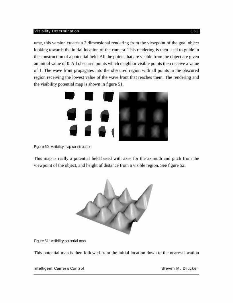
Visibility Determination 162
Intelligent Camera Control Steven M. Drucker
ume, this version creates a 2 dimensional rendering from the viewpoint of the goal object
looking towards the initial location of the camera. This rendering is then used to guide in
the construction of a potential field. All the points that are visible from the object are given
an initial value of 0. All obscured points which neighbor visible points then receive a value
of 1. The wave front propagates into the obscured region with all points in the obscured
region receiving the lowest value of the wave front that reaches them. The rendering and
the visibility potential map is shown in figure 51.
Figure 50: Visibility map construction
This map is really a potential field based with axes for the azimuth and pitch from the
viewpoint of the object, and height of distance from a visible region. See figure 52.
Figure 51: Visibility potential map
This potential map is then followed from the initial location down to the nearest location
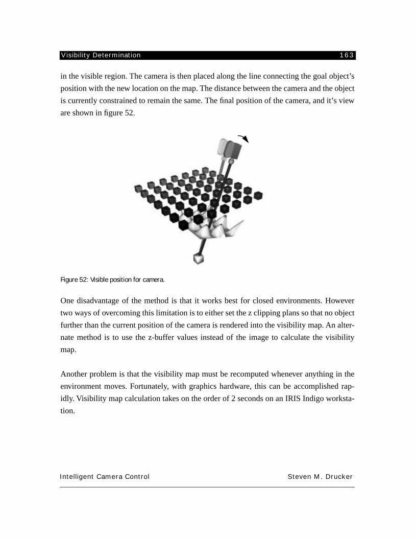
Visibility Determination 163
Intelligent Camera Control Steven M. Drucker
in the visible region. The camera is then placed along the line connecting the goal object’s
position with the new location on the map. The distance between the camera and the object
is currently constrained to remain the same. The final position of the camera, and it’s view
are shown in figure 52.
Figure 52: Visible position for camera.
One disadvantage of the method is that it works best for closed environments. However
two ways of overcoming this limitation is to either set the z clipping plans so that no object
further than the current position of the camera is rendered into the visibility map. An alter-
nate method is to use the z-buffer values instead of the image to calculate the visibility
map.
Another problem is that the visibility map must be recomputed whenever anything in the
environment moves. Fortunately, with graphics hardware, this can be accomplished rap-
idly. Visibility map calculation takes on the order of 2 seconds on an IRIS Indigo worksta-
tion.
Graphical Environment Systems 164
Intelligent Camera Control Steven M. Drucker
APPENDIX 3: GRAPHICAL ENVIRONMENT SYSTEMS
The following section describes the extended 3d graphic system.
Extensions to the 3d environment which was originally described in [Chen92] include the
following: TK (a toolkit for X-window widgets); [incr tcl] (an object oriented extension to
tcl); a port to the Silicon Graphics Graphics Library (GL); support for a head mounted dis-
play; better communication support; visibility calculation; radiosity; raytracing; video
objects; spline fitting and generation; quaternions; and a general constrained optimizer.
This adds to an existing base of tools for dynamic simulation, extensive math and linear
algebra libraries; Denavit-Hartenberg notation; finite element analysis; a general purpose
embeddable interpreter; and multiplatform hardware and software rendering support.
The extended 3d system has been crucial as a prototyping tool for the creation of several
graphical environments including all the environments described in this thesis: mission
planner; CINEMA system; virtual museum; conversation; virtual football game; and sev-
eral others: pumping it up (by David Chen the author of the original system); and an ani-
mation (S.I. with Tinsley Galyean).
Converters have been written which translate a variety of different file formats into files
readable by the extended 3d system including subsets of RIB files (those produced by
Swivel 3D); objects produced by Wavefront; files produced by the Vertigo system; and a
subset of DXF files.
A3.1 TK
TK is an object oriented toolkit built to provide X widget functionality from tcl. It pro-
vides rapid prototyping of widgets and convenient generation of interfaces for various

Graphical Environment Systems 165
Intelligent Camera Control Steven M. Drucker
graphical environments. Extensive use of the canvas widget (a structured graphics editor)
was used for the map-view in the museum; the action view of the football game; and the
interactive graphical programming of camera modules.
A3.2 Communication libraries
Through the addition of TK, interprocess communication is possible between any pro-
cesses running within TK through TK’s send function. This has greatly facilitated indepen-
dent development of algorithms without having to incorporate the algorithms within the
extended 3d system.
An alternate, more special purpose, yet faster method of communication is through the use
of unix pipes. Processes can be spawned by 3d which can then communicate with the sub-
processes through pipes. One advantage of this is that a special protocol can be used to
send binary data back and forth. In addition, the overhead for communicating over the
pipes is less than the more general and flexible interprocess communication provided by
the send function.
A3.3 Head mounted display/dataglove
Support for multiple viewports and hardware tracking was added to extended 3d. It has
currently been used with VPL eyephones. Tracking devices have included the polhemus
isotrack and the Ascension Bird. Tracking information is incorporated into 3d either
through the send mechanism or through pipes to specifically spawned processes which
access the serial ports.
An application which also uses the dataglove was implemented using pipes to a serial pro-
cess which reads the position of the polhemus attached to the dataglove and also returns
the flex values for each of the finger sensors. These flex values were then used to adjust the
Denavit Hartenberg parameters of a simulated robot hand which handled all forward kine-
matics for the model.

Graphical Environment Systems 166
Intelligent Camera Control Steven M. Drucker
A3.4 Radiosity/Raytracing/Visibility
Radiosity is a graphical rendering technique which allows extensive precomputation based
on an energy balance occasion for light propagating through the environment. Calculating
the global illumination of an environment with radiosity greatly enhances the realism of
the perceived space. Of particular importance are shadows and other natural environment
cues which help the user orient themselves within the space. It is because of this enhanced
perception of the environment, and because it incurs no loss of display speed, that radios-
ity has been included in the extended 3d system.
To add radiosity functionality to the 3d system the object database is converted into a for-
mat acceptable by the public domain raytracer known as RayShade [available via ftp at
weedeater.yale.edu]. The visibility calculation libraries from this raytracer have been
incorporated into extended 3d. Once in this form visibility testing between any point in the
environment and any other point in the environment can be performed. Additional struc-
tures are added that store the amount of radiosity gathered at each vertex and thus at each
patch within the graphical database. Adaptive subdivision is also supported. Finally, after
extensive adaptive subdivision methods of converting the resultant complex mesh into a
texture map (for significant increase in the speed of rendering). The database can be stored
along with either the resulting vertex colors or texture maps and reloaded so that radiosity
calculations can be done in advance of interaction.
The visibility database can be a greatly simplified version of the actual database, since it
simply acts as a mask to prevent light from traveling through objects. This visibility data-
base enables arbitrary visibility testing in the environment.
rad_load_database filename
rad_checkvis
rad_shoot [sub]
rad_subdivide
rad_update [gamma]
Rad_checkvis checks the visibility between two world space points based on the radiosity
database.
Rad_shoot computes one round of shooting from the patch with the maximum amount of
unemitted radiosity. If the sub flag is included, then adaptive subdivision of the database
Graphical Environment Systems 167
Intelligent Camera Control Steven M. Drucker
occurs based on the conditions set in the rad_subdiv call.
Rad_subdiv sets subdivision conditions and limits.
Rad_update updates the vertex colors of the database based on the radiosity values stored
at each vertex. If gamma is specified then the color values are scaled by e^gamma.
A3.5 Video Objects
Video objects were created because of the current ability of graphic workstations to dis-
play texture maps using hardware capabilities. Textures can add a great deal of realism to
the image without incurring any loss in performance. This is particularly important in cre-
ating environments which have human beings in them. It is especially important when
specifying camera positions and movements to be able to see a detailed representation of
the human including gaze direction and expression on the face. Modelling humans geo-
metrically is still a current research direction in Computer Graphics and sufficiently realis-
tic models tend to be made of an extremely large number of polygons, or surface patches
(on the order of 10,000+).
The basic strategy for the creation of a video object is to digitize an object from a number
of multiple viewpoints (typically 8 or 16 views from angles around the object). Once these
views have been digitized, and an appropriate alpha channel is created for the background,
the textures are loaded into the machine. The video object is then represented geometri-
cally as a single square polygon scaled to the correct size for the object in relation to other
objects in the environment. When viewing the scene, the polygon representing the video
object is first oriented to face the viewer. Then, the appropriate texture map is selected and
mapped onto the video object based on the angle that the object is meant to be facing (a
normal vector is stored with the video object and can be changed so the object faces differ-
ent directions). See figure 53.
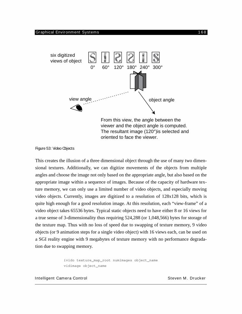
Graphical Environment Systems 168
Intelligent Camera Control Steven M. Drucker
Figure 53: Video Objects
This creates the illusion of a three dimensional object through the use of many two dimen-
sional textures. Additionally, we can digitize movements of the objects from multiple
angles and choose the image not only based on the appropriate angle, but also based on the
appropriate image within a sequence of images. Because of the capacity of hardware tex-
ture memory, we can only use a limited number of video objects, and especially moving
video objects. Currently, images are digitized to a resolution of 128x128 bits, which is
quite high enough for a good resolution image. At this resolution, each “view-frame” of a
video object takes 65536 bytes. Typical static objects need to have either 8 or 16 views for
a true sense of 3-dimensionality thus requiring 524,288 (or 1,048,566) bytes for storage of
the texture map. Thus with no loss of speed due to swapping of texture memory, 9 video
objects (or 9 animation steps for a single video object) with 16 views each, can be used on
a SGI reality engine with 9 megabytes of texture memory with no performance degrada-
tion due to swapping memory.
ivido texture_map_root numimages object_name
vidimage object_name
six digitized views of object
0° 60° 120° 180° 240° 300°
From this view, the angle between the viewer and the object angle is computed. The resultant image (120°)is selected and oriented to face the viewer.
object angleview angle
Graphical Environment Systems 169
Intelligent Camera Control Steven M. Drucker
Ivido creates a video object and loads the specified texture maps into the directory /
vid_textures. If the textures already exist there, then only the object is created and no more
textures are loaded. The number of images can either be 1,8, or 16. The proper angle num-
ber is automatically appended to the name of the texture map. Texture maps be stored in
the form map_name.rgba.angle.
Vidimage calculates the angle that the object should be rotated in order to face the viewer,
and then calculates and maps the image on the object based on the angle between the
object’s internal normal and the viewer to object direction.
A3.6 Object Oriented Tcl [incr tcl]
[incr tcl] was designed by [McClelland92] to be used as an objected oriented extension to
tcl in a similar fashion that C++ is an object oriented extension to C. It provides for object
encapsulation of methods and variables and multiple inheritance. It was used extensively
in the implementation of camera modules and camera agents and made programming in
the 3d environment a joy.
A3.7 General Optimization
A general purpose optimization procedure was embedded in the extended 3d environment.
The system used was a “Feasible Sequential Quadratic Programming ” (FSQP) written by
[Lawrence94]. The procedure was embedded in such a way to allow for tcl routines to act
as the objective function, the gradient of the objective function, constraint functions, and
their gradients. If no derivative is specified, the optimization can calculate the derivatives
by finite differences.
The details of the operation of the fsqp solver and the 3d interface are described in appen-
dix 4.
A3.8 Spline fitting and evaluation
Support for general purpose spline creation, fitting, and interpolation is now incorporated
Graphical Environment Systems 170
Intelligent Camera Control Steven M. Drucker
into the extended 3d system. Fitting is accomplished through a least square adjustment of
control points which have been distributed equally along the arc length of the points to be
fitted. For more information on the technique used see [Barsky83]. Splines can be turned
into polylines that are displayed in 3d and can be incrementally updated. Positions along
the splines can be calculated to provide for a means of smooth keyframed movement for
objects and cameras.
m2splinefit inputm2 numcontrol controlm2
m2spline controlm2 interpolation outputm2
m2splineval controlm2 time
m2obj matrix obj
m2cat mat1 [mat2 ... matn] matoutput
m2hermite controlm2 steps outputm2 [tension]
m2hermiteval controlm2 time outputm2 [tension]
M2splinefit calculates the control points of a B-spline with the specified number of control
points which best fits the input points. This allows convenient smoothing of noisy data.
M2splineval and M2spline use the control points calculated from m2splinefit to generate
either a single 3 dimensional output or a 3xn matrix of outputs where n equals the number
of control points times the number of steps specified.
M2obj turns any matrix into a polyline to be displayed in the system. This permits conve-
nient displays of object or camera paths.
M2cat concatenates any number of m2’s into one large resultant m2s. The matrices need
not have the same number of columns, but the result has the same number of columns as
the maximum input matrix and has number of rows equal to the sum of the number of
rows in each of the input matrices. Extra columns are filled with 0’s.
M2hermite constructs a Kochanack style tension/bias hermite spline through the specified
points. Input can be n-dimensional and output will be mxn based on the number of input
elements specified and the step size.
Graphical Environment Systems 171
Intelligent Camera Control Steven M. Drucker
M2hermiteval returns one point on a Kochanack style tension/bias hermite spline through
the specified points. Input can be n-dimensional while output is 1xn.
A3.9 Quaternions
A quaternion based representation has been incorporated along with utility routines to
translate between a rotation matrix based and quaternion based representations. Quater-
nions enable convenient interpolation of key framed matrices both for the general objects
in the system and for the camera. For more details on quaternions, see [Shoemake87].
quattom2 quat m2
mtoquatn m2 quat
viewtoquatn quat
Quattom2 converts the specified quaternion into the 4 x 4 rotation matrix m2.
Mtoquatn converts the rotation portion of a 4x4 matrix into a normalized quaternion.
Viewtoquat converts the view matrix into a quaternion.
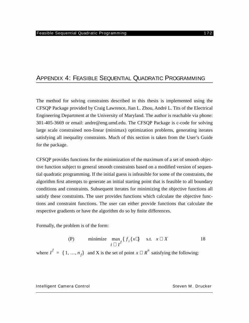
Feasible Sequential Quadratic Programming 172
Intelligent Camera Control Steven M. Drucker
APPENDIX 4: FEASIBLE SEQUENTIAL QUADRATIC PROGRAMMING
The method for solving constraints described in this thesis is implemented using the
CFSQP Package provided by Craig Lawrence, Jian L. Zhou, André L. Tits of the Electrical
Engineering Department at the University of Maryland. The author is reachable via phone:
301-405-3669 or email: [email protected]. The CFSQP Package is c-code for solving
large scale constrained non-linear (minimax) optimization problems, generating iterates
satisfying all inequality constraints. Much of this section is taken from the User’s Guide
for the package.
CFSQP provides functions for the minimization of the maximum of a set of smooth objec-
tive function subject to general smooth constraints based on a modified version of sequen-
tial quadratic programming. If the initial guess is infeasible for some of the constraints, the
algorithm first attempts to generate an initial starting point that is feasible to all boundary
conditions and constraints. Subsequent iterates for minimizing the objective functions all
satisfy these constraints. The user provides functions which calculate the objective func-
tions and constraint functions. The user can either provide functions that calculate the
respective gradients or have the algorithm do so by finite differences.
Formally, the problem is of the form:
(P) 18
where and X is the set of point satisfying the following:
minimize
f i x
( ){ }i I
f∈max s.t. x X
∈
If
1 … n f, ,{ }
= x Rn
∈
Feasible Sequential Quadratic Programming 173
Intelligent Camera Control Steven M. Drucker
19
where with representing the lower bounds for
x
, and
, representing the upper bounds for
x.
The functions represent inequality
constraints, the first n
i
being nonlinear and the next being linear, where
, , . And the functions represent equal-
ity constraints, the first n
e
being nonlinear, and the next being linear, ,
.
A4.1 The CFSQP algorithm
The algorithm proceeds as follows:
1) If the initial guess does not satisfy the linear constraints, CFSQP generates a point satis-
fying these constraints by solving a strictly convex quadratic program (QP).
2) Next, if the initial guess (or the generated initial point) does not satisfy the nonlinear
inequality constraints, CFSQP attempts to generate a point
x
0
by iterating on the problem
of minimizing the maximum of the nonlinear inequality constraints.
3) Nonlinear equality constraints are turned into inequality constraints using a scheme
from Mayne and Polak [??ref].
20
4) The original objective function is replaced by the modified objective
function:
21
bl x bu< <
g j x( ) 0 j,≤ 1 … ni, ,=
g j x( ) c j ni– x,⟨ ⟩ d j ni–– 0 j,≤≡ ni 1 … t
i
, ,+=
h j x( ) 0 j, 1 … ne, ,= =
h j x( ) a j ne– x,⟨ ⟩ b j ne––≡
f i : ℜn ℜ i,→ 1 … n f
, ,= bl
Rn
∈bu
Rn
∈ g
j x( )ti
ni
–
g
i : ℜn ℜ i,→ 1 … n f
, ,= c j
Rn
∈ d
j
Rn
∈ h
j
x
( )te
ne
– a
j
Rn
∈b
j
Rn
∈
h
j x( )
0 j,≤
1 …
ne
, ,
=
f i x( ){ }
i I
f∈max
f m x p,( ) f i x( ){ }i I
f∈max p jh j x( )
j 1=
ne
∑–=
Feasible Sequential Quadratic Programming 174
Intelligent Camera Control Steven M. Drucker
where are positive penalty parameters that are iteratively adjusted.
5) The resulting optimization problem only involves linear constraints and nonlinear ine-
quality constraints, which are all satisfied at successive iterates.
6) The basic SQP direction d
0
is first computed by solving a standard quadratic program
using a positive definite estimate H of the Hessian of the Lagrangian. d
0
is a direction of
descent for the objective function.
7) The direction is further modified to ensure that the resultant point lies within the feasi-
ble region for nonlinear inequality constraints.
Further details on the search used to solve the SQP are found in the user’s manual or
[Lawrence94].
A general interface to CFSQP has been incorporated into the 3d program allowing call-
back functions for the objective functions, the constraint functions, and their derivatives to
be written in TCL. This allows convenient experimentation with different minimization
functions and constraints, however does tend to run fairly slowly (30 seconds is needed for
a typical camera constraint to be run). Once proper results have been achieved for a give
constraint, the constraint functions an be manually translated into C and the resulting min-
imization usually will run at frame rates (15 Hz). Currently, most of the functions that have
been tried have not specified gradient functions but have relied upon the CFSQP to calcu-
late the gradients by finite differences. Specifying gradient functions would improve the
performance even more and a scheme such as described in [Gleicher91] would be useful
for efficient computation of the gradients.
A4.2 Detailed description to 3d fsqp interface.
fsqp nparam nineqn nineq neqn neq [-gradobj func] [-grad-
const constraintfunc] [-print] [-nf numfuncs] [-mode mode]
p j j,
1 …
ne
, ,
=
Feasible Sequential Quadratic Programming 175
Intelligent Camera Control Steven M. Drucker
[-miter maxiters] [-eps epsilon].
Nparam: number of variables in the state vector.
Nineqn: number of nonlinear inequality constraints.
Nineq: total number of nonlinear inequality constraints. (Nineq-Nineqn = number of linear
inequality constraints)
Neqn: number of nonlinear equality constraints.
Neq: total number of equality constraints. (Neq-Neqn = number of linear equality con-
straints)
-gradobj: (optional) for specifying the name of the function that calculates the gradient of
the objective functions, if it is not specified CFSQP calculates the gradient internally by
finite differences.
-gradconst: (optional) argument for specifying the name of the function that calculates the
gradient of the constraint functions, if it is not specified CFSQP calculates the gradient
internally by finite differences.
-print: (optional) flag to print detailed information during the minimization process
-mode: (optional) tells CFSQP to use alternate scheme for solving the minimization pro-
cess. This alternate scheme does not require improvement on each successive iterate but
requires improvement in at most 4 iterations. The scheme requires slightly fewer evalua-
tions of the objective functions.
-miter: (optional) specifies a maximum number of iterations to try before the optimizer
gives up. Defaults at 200 iterations, but solution is usually found before then.
-eps: (optional) specifies an epsilon for which a new iterate is considered to be the same as
the previous iterate, defaults at 1e-5.
When the procedure is called for the first time, the following vectors are set up:
fsqp_state: state vector of specified number of parameters
fsqp_bl: lower bounds on the state vector
fsqp_bu: upper bounds on the state vector
fsqp_display: state information at each iteration to be
displayed by the fsqp_display routine, if display is
turned on (fsqp_display 1).
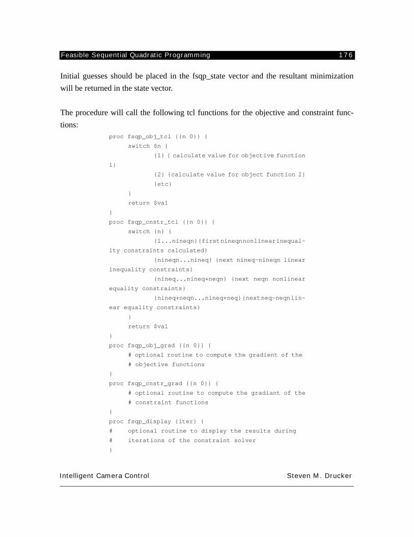
Feasible Sequential Quadratic Programming 176
Intelligent Camera Control Steven M. Drucker
Initial guesses should be placed in the fsqp_state vector and the resultant minimization
will be returned in the state vector.
The procedure will call the following tcl functions for the objective and constraint func-
tions:
proc fsqp_obj_tcl {{n 0}} {
switch $n {
{1} { calculate value for objective function
1}
{2} {calculate value for object function 2}
{etc}
}
return $val
}
proc fsqp_cnstr_tcl {{n 0}} {
switch {n} {
{1...nineqn} {first nineqn nonlinear inequal-
ity constraints calculated}
{nineqn...nineq} {next nineq-nineqn linear
inequality constraints}
{nineq...nineq+neqn} {next neqn nonlinear
equality constraints}
{nineq+neqn...nineq+neq} {next neq-neqn lin-
ear equality constraints}
}
return $val
}
proc fsqp_obj_grad {{n 0}} {
# optional routine to compute the gradient of the
# objective functions
}
proc fsqp_cnstr_grad {{n 0}} {
# optional routine to compute the gradiant of the
# constraint functions
}
proc fsqp_display {iter} {
# optional routine to display the results during
# iterations of the constraint solver
}
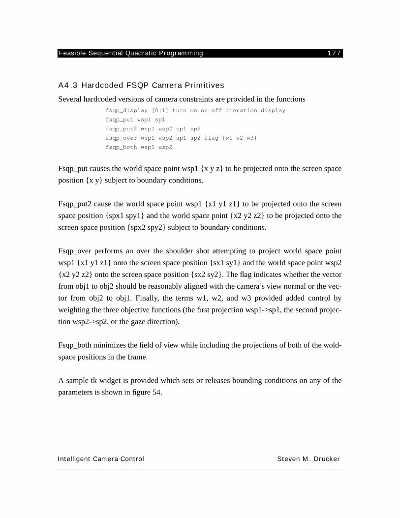
Feasible Sequential Quadratic Programming 177
Intelligent Camera Control Steven M. Drucker
A4.3 Hardcoded FSQP Camera Primitives
Several hardcoded versions of camera constraints are provided in the functions
fsqp_display [0|1] turn on or off iteration display
fsqp_put wsp1 sp1
fsqp_put2 wsp1 wsp2 sp1 sp2
fsqp_over wsp1 wsp2 sp1 sp2 flag [w1 w2 w3]
fsqp_both wsp1 wsp2
Fsqp_put causes the world space point wsp1 {x y z} to be projected onto the screen space
position {x y} subject to boundary conditions.
Fsqp_put2 cause the world space point wsp1 {x1 y1 z1} to be projected onto the screen
space position {spx1 spy1} and the world space point {x2 y2 z2} to be projected onto the
screen space position {spx2 spy2} subject to boundary conditions.
Fsqp_over performs an over the shoulder shot attempting to project world space point
wsp1 {x1 y1 z1} onto the screen space position {sx1 sy1} and the world space point wsp2
{x2 y2 z2} onto the screen space position {sx2 sy2}. The flag indicates whether the vector
from obj1 to obj2 should be reasonably aligned with the camera’s view normal or the vec-
tor from obj2 to obj1. Finally, the terms w1, w2, and w3 provided added control by
weighting the three objective functions (the first projection wsp1->sp1, the second projec-
tion wsp2->sp2, or the gaze direction).
Fsqp_both minimizes the field of view while including the projections of both of the wold-
space positions in the frame.
A sample tk widget is provided which sets or releases bounding conditions on any of the
parameters is shown in figure 54.
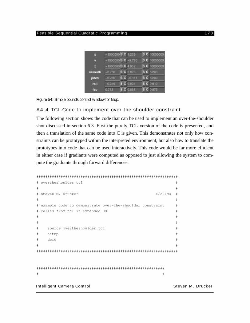
Feasible Sequential Quadratic Programming 178
Intelligent Camera Control Steven M. Drucker
Figure 54: Simple bounds control window for fsqp.
A4.4 TCL-Code to implement over the shoulder constraint
The following section shows the code that can be used to implement an over-the-shoulder
shot discussed in section 6.3. First the purely TCL version of the code is presented, and
then a translation of the same code into C is given. This demonstrates not only how con-
straints can be prototyped within the interpreted environment, but also how to translate the
prototypes into code that can be used interactively. This code would be far more efficient
in either case if gradiants were computed as opposed to just allowing the system to com-
pute the gradiants through forward differences.
################################################################
# overtheshoulder.tcl #
# #
# Steven M. Drucker 4/29/94 #
# #
# example code to demonstrate over-the-shoulder constraint #
# called from tcl in extended 3d #
# #
# #
# source overtheshoulder.tcl #
# setup #
# doit #
# #
################################################################
##########################################################
# #
Feasible Sequential Quadratic Programming 179
Intelligent Camera Control Steven M. Drucker
# routine to set up initial conditions #
# #
##########################################################
proc setup {} {
global iteration
global obj1 obj2
global w1 w2 w3
# load and set up target objects
io cutcube.asc cu
io cutcube.asc cu2
so .25 .25 .25 cu
so .25 .25 .25 cu2
co 1 0 0 cu2
to -1 0 0 cu2
to 1 0 0 cu
# set relative weights for the different constraints
set w1 1
set w2 1
set w3 1
# set the target objects for the minimization
set obj1 cu
set obj2 cu2
# initialize the feasible sequential quadratic minimizer with
# 7 state variables
fsqp_init 7
# set lower and upper bounds on roll (in radians)
m2ele 5 -.01 fsqp_bl
m2ele 5 .01 fsqp_bu
# set lower and upper bounds on zoom between 45 and 50 degrees
m2ele 6 [D2R 45] fsqp_bl
m2ele 6 [D2R 50] fsqp_bu
# load in an initial position
m2load {-3 4 4 2.44 -0.68 0 0.7854} fsqp_state
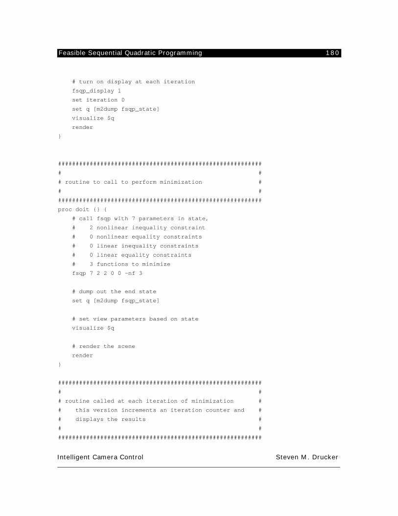
Feasible Sequential Quadratic Programming 180
Intelligent Camera Control Steven M. Drucker
# turn on display at each iteration
fsqp_display 1
set iteration 0
set q [m2dump fsqp_state]
visualize $q
render
}
##########################################################
# #
# routine to call to perform minimization #
# #
##########################################################
proc doit {} {
# call fsqp with 7 parameters in state,
# 2 nonlinear inequality constraint
# 0 nonlinear equality constraints
# 0 linear inequality constraints
# 0 linear equality constraints
# 3 functions to minimize
fsqp 7 2 2 0 0 -nf 3
# dump out the end state
set q [m2dump fsqp_state]
# set view parameters based on state
visualize $q
# render the scene
render
}
##########################################################
# #
# routine called at each iteration of minimization #
# this version increments an iteration counter and #
# displays the results #
# #
##########################################################
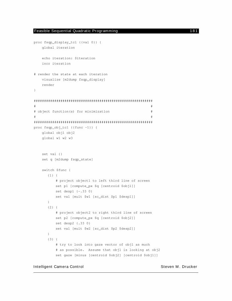
Feasible Sequential Quadratic Programming 181
Intelligent Camera Control Steven M. Drucker
proc fsqp_display_tcl {{val 0}} {
global iteration
echo iteration: $iteration
incr iteration
# render the state at each iteration
visualize [m2dump fsqp_display]
render
}
##########################################################
# #
# object function(s) for minimization #
# #
##########################################################
proc fsqp_obj_tcl {{func -1}} {
global obj1 obj2
global w1 w2 w3
set val {}
set q [m2dump fsqp_state]
switch $func {
{1} {
# project object1 to left third line of screen
set p1 [compute_px $q [centroid $obj1]]
set desp1 {-.33 0}
set val [mult $w1 [sc_dist $p1 $desp1]]
}
{2} {
# project object2 to right third line of screen
set p2 [compute_px $q [centroid $obj2]]
set desp2 {.33 0}
set val [mult $w2 [sc_dist $p2 $desp2]]
}
{3} {
# try to look into gaze vector of obj1 as much
# as possible. Assume that obj1 is looking at obj2
set gaze [minus [centroid $obj2] [centroid $obj1]]
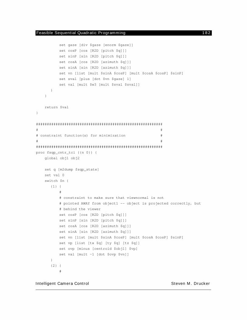
Feasible Sequential Quadratic Programming 182
Intelligent Camera Control Steven M. Drucker
set gaze [div $gaze [enorm $gaze]]
set cosP [cos [R2D [pitch $q]]]
set sinP [sin [R2D [pitch $q]]]
set cosA [cos [R2D [azimuth $q]]]
set sinA [sin [R2D [azimuth $q]]]
set vn [list [mult $sinA $cosP] [mult $cosA $cosP] $sinP]
set sval [plus [dot $vn $gaze] 1]
set val [mult $w3 [mult $sval $sval]]
}
}
return $val
}
##########################################################
# #
# constraint function(s) for minimization #
# #
##########################################################
proc fsqp_cntr_tcl {{n 0}} {
global obj1 obj2
set q [m2dump fsqp_state]
set val 0
switch $n {
{1} {
#
# constraint to make sure that viewnormal is not
# pointed AWAY from object1 -- object is projected correctly, but
# behind the viewer
set cosP [cos [R2D [pitch $q]]]
set sinP [sin [R2D [pitch $q]]]
set cosA [cos [R2D [azimuth $q]]]
set sinA [sin [R2D [azimuth $q]]]
set vn [list [mult $sinA $cosP] [mult $cosA $cosP] $sinP]
set vp [list [tx $q] [ty $q] [tz $q]]
set ovp [minus [centroid $obj1] $vp]
set val [mult -1 [dot $ovp $vn]]
}
{2} {
#
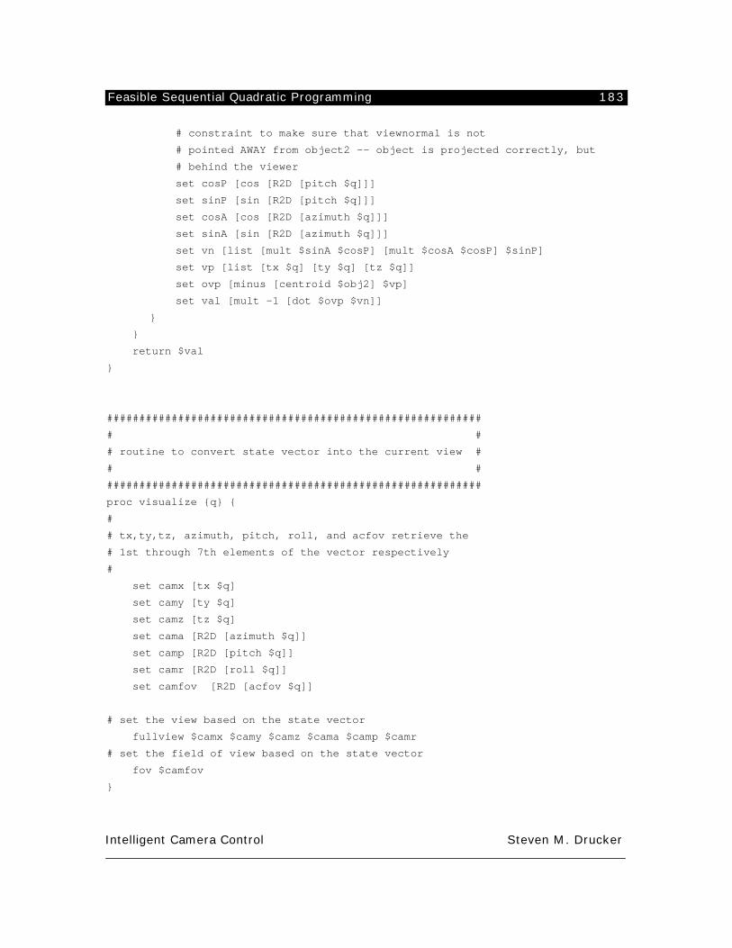
Feasible Sequential Quadratic Programming 183
Intelligent Camera Control Steven M. Drucker
# constraint to make sure that viewnormal is not
# pointed AWAY from object2 -- object is projected correctly, but
# behind the viewer
set cosP [cos [R2D [pitch $q]]]
set sinP [sin [R2D [pitch $q]]]
set cosA [cos [R2D [azimuth $q]]]
set sinA [sin [R2D [azimuth $q]]]
set vn [list [mult $sinA $cosP] [mult $cosA $cosP] $sinP]
set vp [list [tx $q] [ty $q] [tz $q]]
set ovp [minus [centroid $obj2] $vp]
set val [mult -1 [dot $ovp $vn]]
}
}
return $val
}
##########################################################
# #
# routine to convert state vector into the current view #
# #
##########################################################
proc visualize {q} {
#
# tx,ty,tz, azimuth, pitch, roll, and acfov retrieve the
# 1st through 7th elements of the vector respectively
#
set camx [tx $q]
set camy [ty $q]
set camz [tz $q]
set cama [R2D [azimuth $q]]
set camp [R2D [pitch $q]]
set camr [R2D [roll $q]]
set camfov [R2D [acfov $q]]
# set the view based on the state vector
fullview $camx $camy $camz $cama $camp $camr
# set the field of view based on the state vector
fov $camfov
}
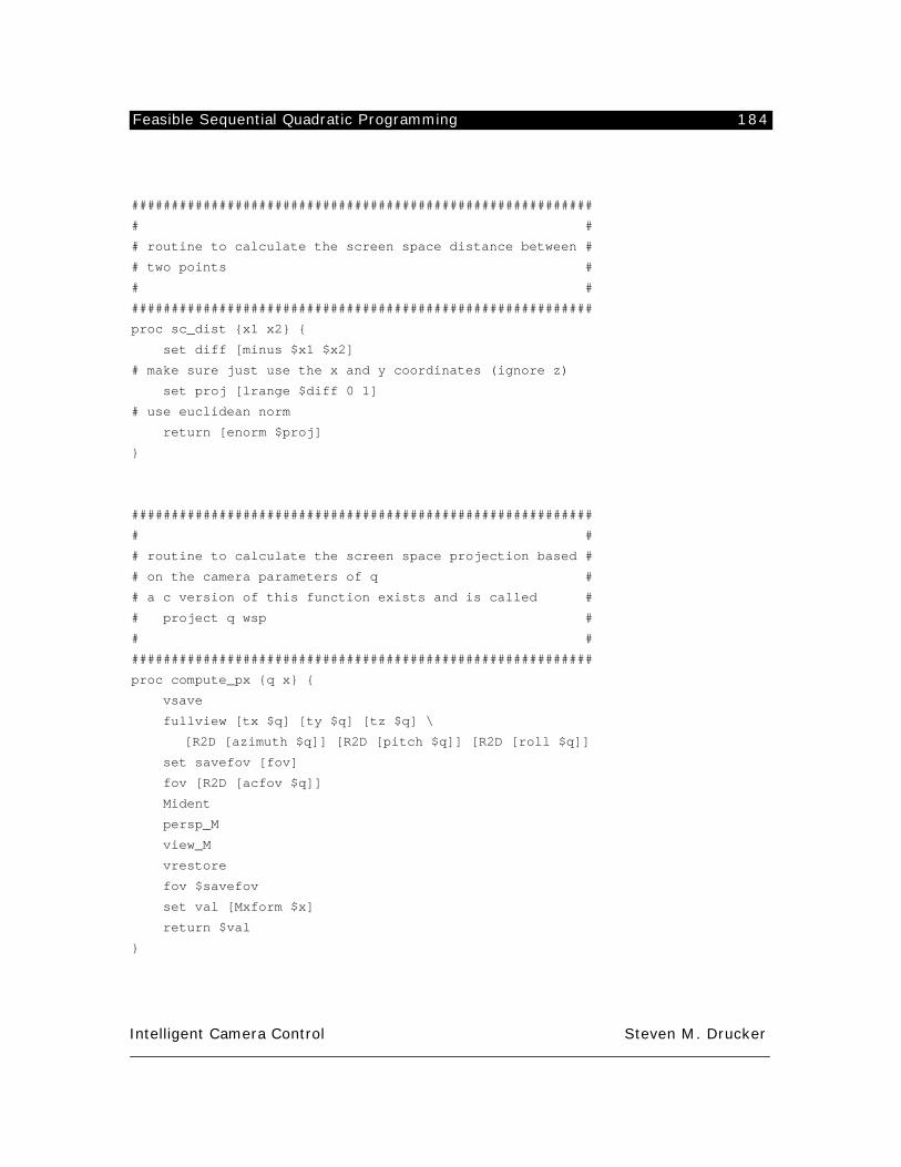
Feasible Sequential Quadratic Programming 184
Intelligent Camera Control Steven M. Drucker
##########################################################
# #
# routine to calculate the screen space distance between #
# two points #
# #
##########################################################
proc sc_dist {x1 x2} {
set diff [minus $x1 $x2]
# make sure just use the x and y coordinates (ignore z)
set proj [lrange $diff 0 1]
# use euclidean norm
return [enorm $proj]
}
##########################################################
# #
# routine to calculate the screen space projection based #
# on the camera parameters of q #
# a c version of this function exists and is called #
# project q wsp #
# #
##########################################################
proc compute_px {q x} {
vsave
fullview [tx $q] [ty $q] [tz $q] \
[R2D [azimuth $q]] [R2D [pitch $q]] [R2D [roll $q]]
set savefov [fov]
fov [R2D [acfov $q]]
Mident
persp_M
view_M
vrestore
fov $savefov
set val [Mxform $x]
return $val
}
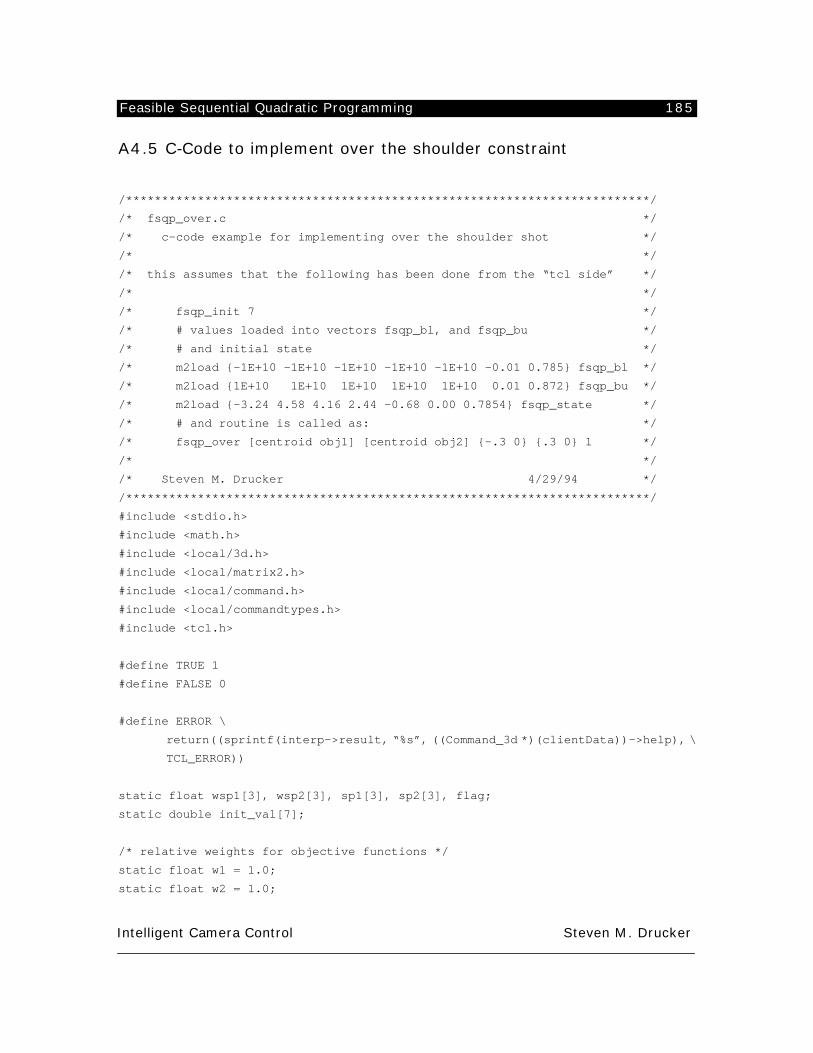
Feasible Sequential Quadratic Programming 185
Intelligent Camera Control Steven M. Drucker
A4.5 C-Code to implement over the shoulder constraint
/*************************************************************************/
/* fsqp_over.c */
/* c-code example for implementing over the shoulder shot */
/* */
/* this assumes that the following has been done from the “tcl side” */
/* */
/* fsqp_init 7 */
/* # values loaded into vectors fsqp_bl, and fsqp_bu */
/* # and initial state */
/* m2load {-1E+10 -1E+10 -1E+10 -1E+10 -1E+10 -0.01 0.785} fsqp_bl */
/* m2load {1E+10 1E+10 1E+10 1E+10 1E+10 0.01 0.872} fsqp_bu */
/* m2load {-3.24 4.58 4.16 2.44 -0.68 0.00 0.7854} fsqp_state */
/* # and routine is called as: */
/* fsqp_over [centroid obj1] [centroid obj2] {-.3 0} {.3 0} 1 */
/* */
/* Steven M. Drucker 4/29/94 */
/*************************************************************************/
#include <stdio.h>
#include <math.h>
#include <local/3d.h>
#include <local/matrix2.h>
#include <local/command.h>
#include <local/commandtypes.h>
#include <tcl.h>
#define TRUE 1
#define FALSE 0
#define ERROR \
return((sprintf(interp->result, “%s”, ((Command_3d *)(clientData))->help), \
TCL_ERROR))
static float wsp1[3], wsp2[3], sp1[3], sp2[3], flag;
static double init_val[7];
/* relative weights for objective functions */
static float w1 = 1.0;
static float w2 = 1.0;
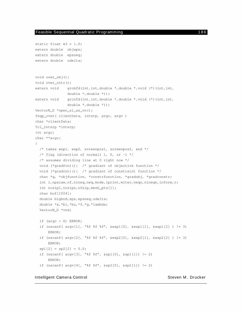
Feasible Sequential Quadratic Programming 186
Intelligent Camera Control Steven M. Drucker
static float w3 = 1.0;
extern double objeps;
extern double epsneq;
extern double udelta;
void over_obj();
void over_cntr();
extern void grobfd(int,int,double *,double *,void (*)(int,int,
double *,double *));
extern void grcnfd(int,int,double *,double *,void (*)(int,int,
double *,double *));
VectorN_D *open_sl_as_vn();
fsqp_over( clientData, interp, argc, argv )
char *clientData;
Tcl_Interp *interp;
int argc;
char **argv;
{
/* takes wsp1, wsp2, screenpos1, screenpos2, and */
/* flag (direction of normal) 1, 0, or -1 */
/* assumes dividing line at 0 right now */
void (*gradfcn)(); /* gradiant of objective function */
void (*gradcnt)(); /* gradiant of constraint function */
char *q, *objfunction, *constrfunction, *gradobj, *gradconstr;
int i,nparam,nf,nineq,neq,mode,iprint,miter,neqn,nineqn,inform,r;
int ncsipl,ncsipn,nfsip,mesh_pts[1];
char buf[1024];
double bigbnd,eps,epsneq,udelta;
double *x,*bl,*bu,*f,*g,*lambda;
VectorN_D *vnd;
if (argc < 6) ERROR;
if (sscanf( argv[1], “%f %f %f”, &wsp1[0], &wsp1[1], &wsp1[2] ) != 3)
ERROR;
if (sscanf( argv[2], “%f %f %f”, &wsp2[0], &wsp2[1], &wsp2[2] ) != 3)
ERROR;
sp1[2] = sp2[2] = 0.0;
if (sscanf( argv[3], “%f %f”, &sp1[0], &sp1[1]) != 2)
ERROR;
if (sscanf( argv[4], “%f %f”, &sp2[0], &sp2[1]) != 2)
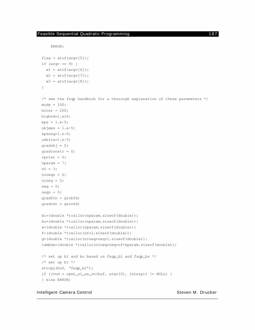
Feasible Sequential Quadratic Programming 187
Intelligent Camera Control Steven M. Drucker
ERROR;
flag = atof(argv[5]);
if (argc == 9) {
w1 = atof(argv[6]);
w2 = atof(argv[7]);
w3 = atof(argv[8]);
}
/* see the fsqp handbook for a thorough explanation of these parameters */
mode = 100;
miter = 200;
bigbnd=1.e10;
eps = 1.e-5;
objeps = 1.e-5;
epsneq=1.e-5;
udelta=1.e-5;
gradobj = 0;
gradconstr = 0;
iprint = 0;
nparam = 7;
nf = 3;
nineqn = 2;
nineq = 2;
neq = 0;
neqn = 0;
gradfcn = grobfd;
gradcnt = grcnfd;
bl=(double *)calloc(nparam,sizeof(double));
bu=(double *)calloc(nparam,sizeof(double));
x=(double *)calloc(nparam,sizeof(double));
f=(double *)calloc(nf+1,sizeof(double));
g=(double *)calloc(nineq+neq+1,sizeof(double));
lambda=(double *)calloc(nineq+neq+nf+nparam,sizeof(double));
/* set up bl and bu based on fsqp_bl and fsqp_bu */
/* set up bl */
strcpy(buf, “fsqp_bl”);
if ((vnd = open_sl_as_vn(buf, argv[0], interp)) != NULL) {
} else ERROR;
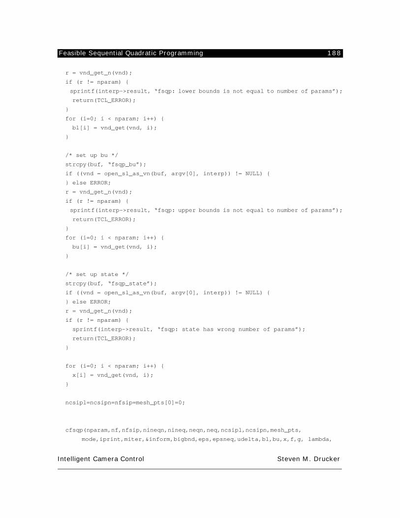
Feasible Sequential Quadratic Programming 188
Intelligent Camera Control Steven M. Drucker
r = vnd_get_n(vnd);
if (r != nparam) {
sprintf(interp->result, “fsqp: lower bounds is not equal to number of params”);
return(TCL_ERROR);
}
for (i=0; i < nparam; i++) {
bl[i] = vnd_get(vnd, i);
}
/* set up bu */
strcpy(buf, “fsqp_bu”);
if ((vnd = open_sl_as_vn(buf, argv[0], interp)) != NULL) {
} else ERROR;
r = vnd_get_n(vnd);
if (r != nparam) {
sprintf(interp->result, “fsqp: upper bounds is not equal to number of params”);
return(TCL_ERROR);
}
for (i=0; i < nparam; i++) {
bu[i] = vnd_get(vnd, i);
}
/* set up state */
strcpy(buf, “fsqp_state”);
if ((vnd = open_sl_as_vn(buf, argv[0], interp)) != NULL) {
} else ERROR;
r = vnd_get_n(vnd);
if (r != nparam) {
sprintf(interp->result, “fsqp: state has wrong number of params”);
return(TCL_ERROR);
}
for (i=0; i < nparam; i++) {
x[i] = vnd_get(vnd, i);
}
ncsipl=ncsipn=nfsip=mesh_pts[0]=0;
cfsqp(nparam,nf,nfsip,nineqn,nineq,neqn,neq,ncsipl,ncsipn,mesh_pts,
mode,iprint,miter,&inform,bigbnd,eps,epsneq,udelta,bl,bu,x,f,g, lambda,
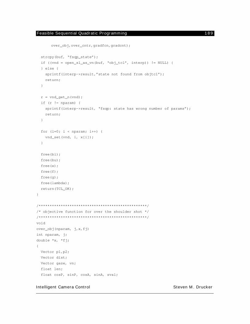
Feasible Sequential Quadratic Programming 189
Intelligent Camera Control Steven M. Drucker
over_obj,over_cntr,gradfcn,gradcnt);
strcpy(buf, “fsqp_state”);
if ((vnd = open_sl_as_vn(buf, “obj_tcl”, interp)) != NULL) {
} else {
sprintf(interp->result,”state not found from objtcl”);
return;
}
r = vnd_get_n(vnd);
if (r != nparam) {
sprintf(interp->result, “fsqp: state has wrong number of params”);
return;
}
for (i=0; i < nparam; i++) {
vnd_set(vnd, i, x[i]);
}
free(bl);
free(bu);
free(x);
free(f);
free(g);
free(lambda);
return(TCL_OK);
}
/*************************************************/
/* objective function for over the shoulder shot */
/*************************************************/
void
over_obj(nparam, j,x,fj)
int nparam, j;
double *x, *fj;
{
Vector p1,p2;
Vector dist;
Vector gaze, vn;
float len;
float cosP, sinP, cosA, sinA, sval;
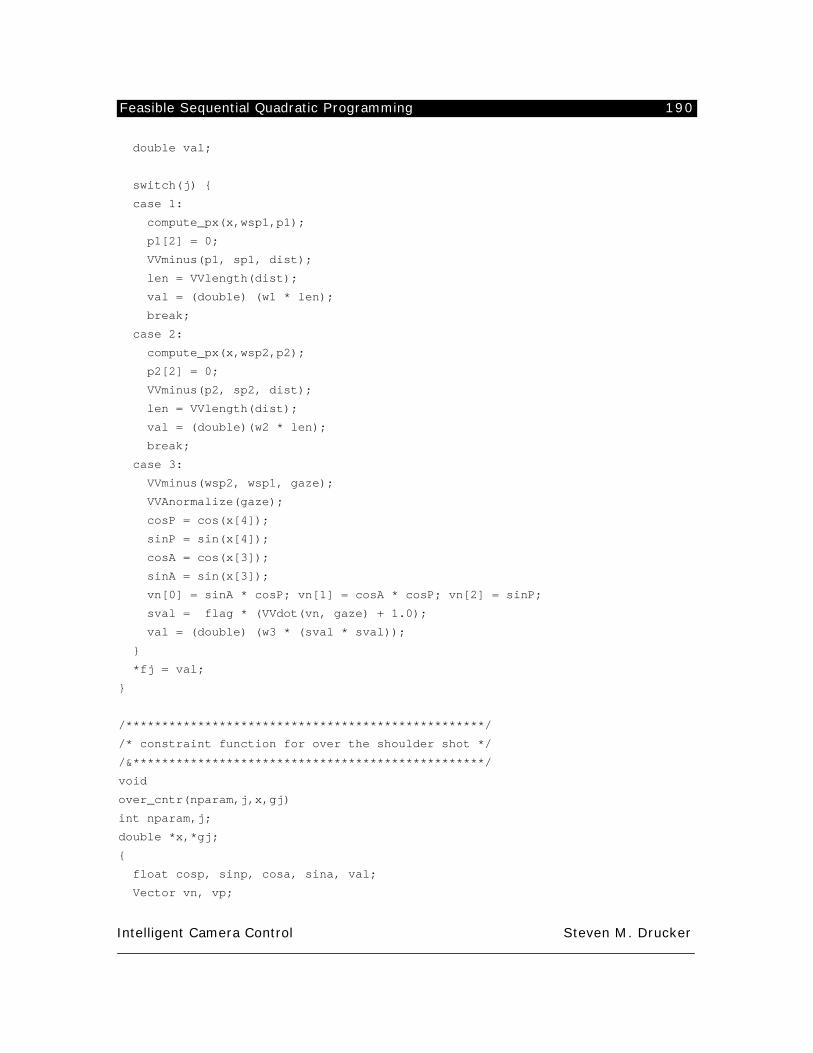
Feasible Sequential Quadratic Programming 190
Intelligent Camera Control Steven M. Drucker
double val;
switch(j) {
case 1:
compute_px(x,wsp1,p1);
p1[2] = 0;
VVminus(p1, sp1, dist);
len = VVlength(dist);
val = (double) (w1 * len);
break;
case 2:
compute_px(x,wsp2,p2);
p2[2] = 0;
VVminus(p2, sp2, dist);
len = VVlength(dist);
val = (double)(w2 * len);
break;
case 3:
VVminus(wsp2, wsp1, gaze);
VVAnormalize(gaze);
cosP = cos(x[4]);
sinP = sin(x[4]);
cosA = cos(x[3]);
sinA = sin(x[3]);
vn[0] = sinA * cosP; vn[1] = cosA * cosP; vn[2] = sinP;
sval = flag * (VVdot(vn, gaze) + 1.0);
val = (double) (w3 * (sval * sval));
}
*fj = val;
}
/**************************************************/
/* constraint function for over the shoulder shot */
/&*************************************************/
void
over_cntr(nparam,j,x,gj)
int nparam,j;
double *x,*gj;
{
float cosp, sinp, cosa, sina, val;
Vector vn, vp;
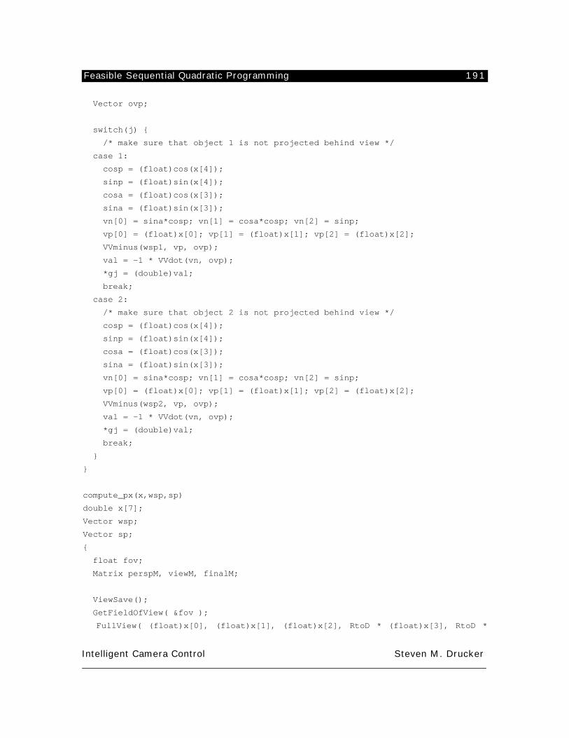
Feasible Sequential Quadratic Programming 191
Intelligent Camera Control Steven M. Drucker
Vector ovp;
switch(j) {
/* make sure that object 1 is not projected behind view */
case 1:
cosp = (float)cos(x[4]);
sinp = (float)sin(x[4]);
cosa = (float)cos(x[3]);
sina = (float)sin(x[3]);
vn[0] = sina*cosp; vn[1] = cosa*cosp; vn[2] = sinp;
vp[0] = (float)x[0]; vp[1] = (float)x[1]; vp[2] = (float)x[2];
VVminus(wsp1, vp, ovp);
val = -1 * VVdot(vn, ovp);
*gj = (double)val;
break;
case 2:
/* make sure that object 2 is not projected behind view */
cosp = (float)cos(x[4]);
sinp = (float)sin(x[4]);
cosa = (float)cos(x[3]);
sina = (float)sin(x[3]);
vn[0] = sina*cosp; vn[1] = cosa*cosp; vn[2] = sinp;
vp[0] = (float)x[0]; vp[1] = (float)x[1]; vp[2] = (float)x[2];
VVminus(wsp2, vp, ovp);
val = -1 * VVdot(vn, ovp);
*gj = (double)val;
break;
}
}
compute_px(x,wsp,sp)
double x[7];
Vector wsp;
Vector sp;
{
float fov;
Matrix perspM, viewM, finalM;
ViewSave();
GetFieldOfView( &fov );
FullView( (float)x[0], (float)x[1], (float)x[2], RtoD * (float)x[3], RtoD *
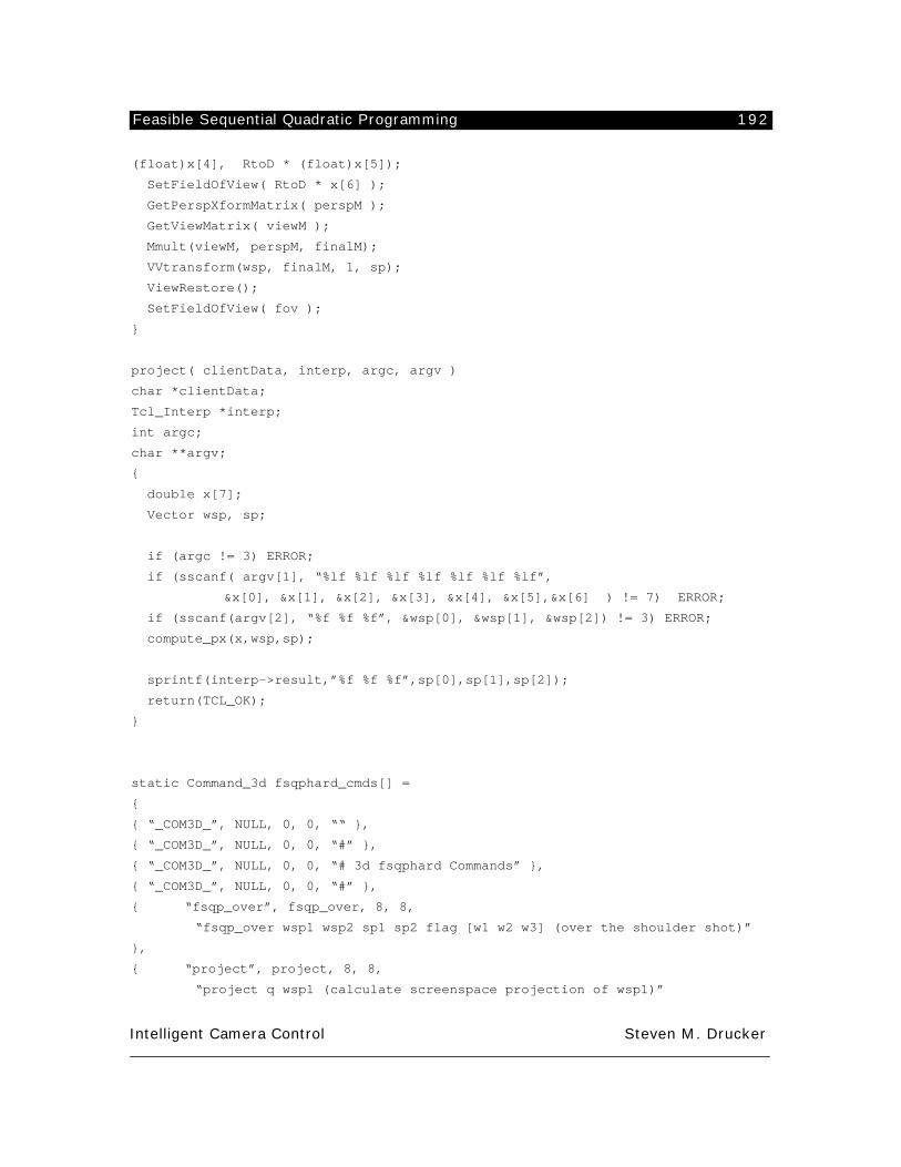
Feasible Sequential Quadratic Programming 192
Intelligent Camera Control Steven M. Drucker
(float)x[4], RtoD * (float)x[5]);
SetFieldOfView( RtoD * x[6] );
GetPerspXformMatrix( perspM );
GetViewMatrix( viewM );
Mmult(viewM, perspM, finalM);
VVtransform(wsp, finalM, 1, sp);
ViewRestore();
SetFieldOfView( fov );
}
project( clientData, interp, argc, argv )
char *clientData;
Tcl_Interp *interp;
int argc;
char **argv;
{
double x[7];
Vector wsp, sp;
if (argc != 3) ERROR;
if (sscanf( argv[1], “%lf %lf %lf %lf %lf %lf %lf”,
&x[0], &x[1], &x[2], &x[3], &x[4], &x[5],&x[6] ) != 7) ERROR;
if (sscanf(argv[2], “%f %f %f”, &wsp[0], &wsp[1], &wsp[2]) != 3) ERROR;
compute_px(x,wsp,sp);
sprintf(interp->result,”%f %f %f”,sp[0],sp[1],sp[2]);
return(TCL_OK);
}
static Command_3d fsqphard_cmds[] =
{
{ “_COM3D_”, NULL, 0, 0, ““ },
{ “_COM3D_”, NULL, 0, 0, “#” },
{ “_COM3D_”, NULL, 0, 0, “# 3d fsqphard Commands” },
{ “_COM3D_”, NULL, 0, 0, “#” },
{ “fsqp_over”, fsqp_over, 8, 8,
“fsqp_over wsp1 wsp2 sp1 sp2 flag [w1 w2 w3] (over the shoulder shot)”
},
{ “project”, project, 8, 8,
“project q wsp1 (calculate screenspace projection of wsp1)”
Feasible Sequential Quadratic Programming 193
Intelligent Camera Control Steven M. Drucker
},
{ NULL }
};
CommandList_3d_Add_fsqphard( command_root )
CommandList_3d *command_root;
{
if (!CommandList_3d_Add_Commands( command_root, fsqphard_cmds ))
{fprintf( stderr, “CommandList_3d_Add_fsqp: failed\n”);
return( FALSE );
}
return( TRUE );
}
References 194
Intelligent Camera Control Steven M. Drucker
References
Adam, J. A. (October 1993). “Virtual Reality is for Real.” IEEE Spectrum 30(10): 22-29.
Airey, J. M., J. H. Rohlf, et al. (March 25-28, 1990). Towards Image Realism with Interactive Update Rates
in Complex Virtual Building Environments. Proc. 1990 Symposium on Interactive 3D Graphics.
Arijon, D. (1976). Grammar of the Film Language. Hollywood, CA., Silman-James Press.
Appino, P. A., J. B. Lewis, et al. (March 1992). “An Architecture for Virtual Worlds.” Presence: Teleopera-
tors and Virtual Environments 1(1): 1-17.
Arkin, R. C. (August 1989). “Motor Schema-Based Mobile Robot Navigation.” International Journal of
Robotics Research 8(4): 92-112.
Armstrong, W. W., M. Green, et al. (June 1987). “Near-Real-Time Control of Human Figure Models.” IEEE
Computer Grahics and Applications 7(6): 52-61.
Asseo, S. J. (May 23-27, 1988). Terrain Following/Terrain Avoidance Path Optimization Using the Method
of Steepest Descent. Proc. IEEE 1988 National Aerospace and Electronics Conf., Dayton OH.
Badler, N. I., K. H. Manoochehri, et al. (October 23-24, 1986). Multi-Dimensional Input Techniques and
Articulated Figure Positioning by Multiple Constraints. Proc. 1986 ACM Workshop on Interactive Graphics.
Baecker, R. M. and W. A. S. Buxton, Ed. (1987). Readings in Human-Computer Interaction. Los Altos CA,
Morgan Kaufmann.
Baecker, R. (1987). Towards an Effective Characterization of Graphical Interaction. Readings in Human-
Computer Interaction. Los Altos CA, Morgan Kaufmann. 471-481.
Balaguer, F. and A. Mangili (1991). Virtual Environments. New Trends in Animation and Visualization.
Chichester, England, John Wiley & Sons. 91-105.
Barr, A. H., B. Currin, et al. (1992). “Smooth interpolation of orientations with angular velocity constraints
using quaternions.” Computer Graphics 26(2): 313-320.
References 195
Intelligent Camera Control Steven M. Drucker
Barraquand, J., B. Langlois, et al. (1989). Numerical Potential Field Techniques for Robot Path Planning.
Stanford University.
Barsky, B. (July 1983). “Local Control of Bias and Tension in Beta-splines.” Computer Graphics 17(3): 193-
218.
Bartels, R., J. Beatty, et al. (1987). An Introduction to Splines for Use in Computer Graphics and Geometric
Modeling. Los Angeles, CA., Morgan Kaufmann.
Barzel, R. and A. H. Barr (August 1988). Controlling Rigid Bodies with Dynamic Constraints. SIGGRAPH
88 Course Notes, Developments in Physically-Based Modeling, Atlanta GA,
Barzel, R. and A. H. Barr (August 1988). “A Modeling System Based on Dynamic Constraints.” Computer
Graphics 22(4): 179-188.
Bass, L. and J. Coutax (1992). Developing Software for the User Interface. Reading MA, Addison-Wesley.
Bate, S. and K. Stanley (May 23-27, 1988). Heuristic Route Planning: An Application to Fighter Aircraft.
Proc. IEEE 1988 National Aerospace and Electronics Conf., Dayton OH.
Bejczy, A. K. and M. Handlykon (1981). Experimental results with a six degree of freedom force reflecting
hand controller. Seventeenth annual conference on manual control., Los Angeles, CA..
Berlyne, D. Structure and Direction in Human Thinking, (John Wiley, New York, 1967).
Bier, E. (March 25-28, 1990). Snap-Dragging in Three Dimensions. Proc. 1990 Symposium on Interactive
3D Graphics.
Bishop, G., W. Bricken, et al. (August 1992). “Research Direction in Virtual Environments.” Computer
Graphics 26(3): 153-177.
Blanchard, C., S. Burgess, et al. (March 25-28, 1990). Reality Built for Two: A Virtual Reality Tool. Proc.
1990 Symposium on Interactive 3D Graphics.
Blau, B., C. E. Hughes, et al. (March 29-April 1, 1992). Networked Virtual Environments. Proc. 1992 Sym-
posium on Interactive 3D Graphics, Cambridge MA: ACM Press.
Blinn, J. (July 1988). “Where am I? What am I looking at?” IEEE Computer Graphics and Applications : 76-
References 196
Intelligent Camera Control Steven M. Drucker
81.
Boies, S., M. Green, et al. (Nov. 13-15, 1989). Panel: Direct Manipulation or Programming: How Should We
Design User Interfaces? Proc. ACM SIGGRAPH Symposium on User Interface Software and Technolgy.
Bolt, R. A., The integrated multi-modal interface. Transaction of the Institute of Electronics, Information,
and Communication Engineers (Japan), Vol. 70-D, 2017-2025 (1987).
Borning, A. (July 1979). Thinglab -- A Constraint-Oriented Simulation Laboratory. Palo Alto CA, Xerox
PARC.
Braitenberg, V. (1984). Vehicles: Experiments in Synthetic Psychology. Cambridge MA, MIT Press.
Brooks, R. A. (1982). Solving the Find-Path Problem by Good Representation of Free Space. Proc. National
Conf. on Artificial Intelligence, AAAI.
Brooks, F. P., Jr. (May 15-19, 1988). Grasping Reality Through Illusion -- Interactive Graphics Serving Sci-
ence. Proc. CHI '88.
Brooks, F. P., Jr. (October 23-24, 1986). Walkthrough -- A Dynamic Graphics System for Simulating Virtual
Buildings. Proc. 1986 ACM Workshop on Interactive 3D Graphics.
Brooks, R. A. (1986). Achieving Artificial Intelligence through Building Insects. MIT.
Brooks, R. (1991). Comparative Task Analysis: An Alternative Direction for Human-Computer Interaction
Science. Designing Interaction: Psychology at the Human-Computer Interface. Cambridge, England, Cam-
bridge University Press. 50-59.
Brotman, L. S. and A. Netravali (August 1988). “Motion Interpolation by Optimal Control.” Computer
Graphics 22(4): 309-315.
Bruderlin, A. and T. W. Calvert (1989). Goal-Directed, Dynamic Animation of Human Walking. Proc. ACM
SIGGRAPH 89, Boston MA.
Burch, Noel. (1981). Theory of Film Practice. University Press. New York.
J. M. Carroll and M.B. Rosson, "Paradox of the Active User" in Interfacing Thought .J. M. Carroll, Ed. (MIT
Press, Cambridge, MA, 1987).
References 197
Intelligent Camera Control Steven M. Drucker
J. M. Carroll and R.L. Campbell, "Artifacts as Psychological Theories: The case of human-computer interac-
tion." (IBM Research Division:T.J. Watson Research Center, 1988).
Carroll, J. M., Ed. (1991). Designing Interaction: Psychology at the Human-Computer Interface. Cam-
bridge, England, Cambridge University Press.
Chamberlain, D. B. and C. R. Kirklen (May 23-27, 1988). Advanced Mission Planning System (AMPS)
Employing Terrain and Intelligence Database Support. Proc. IEEE 1988 National Aerospace and Electronics
Conf., Dayton OH.
Chen, D. T. (December 1991). Pump It Up: Computer Animation of a Biomechanically Based Model of
Muscle Using the Finite Element Method. Cambridge MA, Massachusetts Institute of Technology.
Chen, D. T. and D. Zeltzer (August 1992). The 3d Virtual Environment and Dynamic Simulation System.
Cambridge MA, MIT Media Lab.
Chen, M., S.J. Mountford, A. Sellen. (1988). A Study of Interactive 3D Rotation Using 2D Control Devices.
Proceedings of SIGGRAPH ‘88 (Atlanta, Georgia). In Computer Graphics 22(4):121-129.
Cheshire, David. (1974). The Book of Movie Photography. Alfred A. Knopf: New York.
Chin, N. and S. Feiner (1989). “Near Real-Time Shadow Generation using BSP Trees.” Computer Graphics
23(3): 99-106.
Cohen, M. (1992). “Interactive Spacetime Control of Animation.” Computer Graphics 26(2): 293-302.
Cornsweet, T. N. (1970). Visual Perception. San Diego, Harcourt Brace Jovanovich.
Cotterman, W. W. and K. Kumar (1989). “User Cube: A Taxonomy of End Users.” Communications of the
ACM 32(11): 1313-1320.
Cowan, C. P. Kovesi. (1987) Automatic sensor placement from vision task requirements. Technical Report.
SRI. Menlo Park. CA. June.
Cypher, A., Ed. (1993). Watch What I Do: Programming by Demonstration. Cambridge MA, MIT Press.
Das, H. (1989). Kinematic Control and Visual Display of Redundant Telemanipulators. PhD Thesis. MIT.
References 198
Intelligent Camera Control Steven M. Drucker
Drucker, S. M. and D. Zeltzer (1994). Intelligent Camera Control for Virtual Environments. Graphics Inter-
face '94.
Drucker, S., T. Galyean, et al. (March 29-April 1, 1992). CINEMA: A System for Procedural Camera Move-
ments. Proc. 1992 Symposium on Interactive 3D Graphics, Cambridge MA: ACM Press.
Earnshaw, R. A. (1991). Tools and Techniques for Scientific Visualization. New Trands in Animation and
Visualization. Chichester, England, John Wiley & Sons. 107-114.
Earnshaw, R. A., M. A. Gigante, et al., Ed. (1993). Virtual Reality Systems. London, Academic Press.
Eisendratt, E. (1994). Sports Director for WBZ-TV news in Boston, MA. Personal communication.
Ellis, S. R., Ed. (1991). Pictorial Communication in Virtual and Real Environments. London, Taylor & Fran-
cis Ltd.
Esakov, Jeffrey, Badler, N. Jung, M. (1989). An investigation of language input and performance timing for
task animation. In Proc. Graphics Interface 89. London, Ontario. June. 19-23.
Esakov, J. and N. I. Badler (1991). An Architecture for High-Level Human Task Animation Control. Knowl-
edge-Based Simulation. New York, Springer-Verlag. 162-199.
Esposito, C. (1993). Virtual Reality: Perspectives, Applications and Architecture. User Interface Software.
Chichester, England, John Wiley & Sons. 103-127.
Evans, K. B., P. P. Tanner, et al. (1981). “Human Spatial Orientation. Tablet based valuators that provide one,
two, or three degrees of freedom.” Computer Graphics 15(3): 91-97.
Eyles, D. E. (1991). A computer graphics system for visualizing spacecraft in orbit. Pictorial communication
in virtual and real environments. London, Taylor & Francis. 196-231.
Fisher, S. S., M. McGreevy, et al. (October 23-24, 1986). Virtual Environment Display System. Proc. 1986
ACM Workshop on Interactive Graphics.
Fleishman, E. A. and M. K. Quaintance (1984). Taxonomies of Human Performance. Orlando FL, Academic
Press.
References 199
Intelligent Camera Control Steven M. Drucker
Foley, J. D. (October 1987). “Interfaces for Advanced Computing.” Scientific American 257(4): 126-135.
Foley, J. D. and A. V. Dam (1982). Fundamentals of Interactive Computer Graphics. Addison-Wesley.
Foley, J. D., A. v. Dam, S. Feiner, J. Hughes (1990). Computer Graphics: Principles and Practice. Addison-
Wesley.
Gill, P. E., W. Murray, et al. (1981). Practical Optimization. San Diego, CA., Academic Press.
Girard, M. (June 1987). “Interactive Design of 3D Computer-Animated Legged Animal Motion.” IEEE
Computer Graphics and Applications 7(6): 39-51.
Gleicher, M. (1992). Briar - a constraint based drawing program. SIGCHI '92.
Gleicher, M. and A. Witkin (1992). “Through-the-Lens Camera Control.” Computer Graphics 26(2): 331-
340.
Gomez, J. E. (September 1984). Twixt: A 3-D Animation System. Proc. Eurographics '84, North-Holland.
Greenberg, D. P. (May 1974). “Computer Graphics in Architecture.” Scientific American 230(5): 98-106.
Haeberli, P. E. (August 1988). “ConMan: A Visual Programming Language for Interactive Graphics.” Com-
puter Graphics 22(4): 103-111.
Hagen, Margeret. H. Elliot. (1976). An investigation of the relationship between viewing condition and pref-
erence for true and modified linear perspective with adults. Journal of Experimental Psychology: Human
Perception and Performance. 2(4):479-490.
Hart, P. E., N. J. Nilsson, et al. (1968). “A Formal Basis for the Heuristic Determination of Minimum Cost
Paths.” IEEE Transactions on Systems Science and Cybernetics 4(2): 100-107.
Hochberg, J. (1986). Representation of Motion and Space in Video and Cinematic Displays. Handbook of
Perception and Human Performance. New York, Wiley. 22-1 - 22-64.
Hochberg, J. (1990). Combining Views. Human Performance Models for Computer-Aided Engineering.
Boston MA, Academic Press. 159-165.
Hochberg, J. and V. Brooks (1978). The Perception of Motion Pictures. Handbook of Perception. New York,
References 200
Intelligent Camera Control Steven M. Drucker
Academic Press. 259-304.
Hopcroft, J. E., J. T. Schwartz, et al. (Winter 1984). “On the Complexity of Motion Planning for Multiple
Independent Objects; PSPACE-Hardness of the "Warehousman's Problem".” International Journal of Robot-
ics Research 3(4): 76-88.
Horn, B. (1986). Robot Vision. Cambridge, MA., MIT Press.
Hutchins, E. L., J. D. Hollans, et al. (1986). Direct Manipulation Interfaces. User Centered System Design:
New Perspectives on Human-Computer Interaction. Hillsdale, NJ., Lawrence Erlbaum Associates. 87-124.
Isaacs, P. M. and M. F. Cohen (December 1988). “Mixed Methods for complex Kinematic Constraints in
Dynamic Figure Animation.” The Visual Computer 4(6): 296-305.
Isaacs, P. M. and M. F. Cohen (July 1987). Controlling Dynamic Simulation with Kinematic Constraints,
Behavior Functions and Inverse Dynamics. Proc. ACM SIGGRAPH 87, Anaheim CA.
Isenhour, J. P. (1975). “The Effects of Context and Order in Film Editing.” AV Communication Review
23(1): 69-80.
Kalra, D. and A. Barr (1990). A Constaint-Based Figure-Maker. Eurographics '90.
Kamada, Tomihisa. and Kawai. S.(1988). A simple method for computing general position in displaying
three-dimensional objects. Computer Vision, Graphics, and Image Processing, 41(1):43-56, January.
Kant, K. and S. W. Zucker (1986). “Planning Collision-Free Trajectories in Time-Varying Environments.”
The Visual Computer 2: 304-313.
Karp, P., S.Feiner. (1990). Issues in the Automated Generation of Animated Presentations. Graphics Inter-
face '90 (Halifax, Nova Scotia). 39-48.
Kass, M. (1991). GO: A Graphical Optimizer. ACM SIGGRAPH 91 Course Notes, Introduction to Physi-
cally Based Modeling, Las Vegas NM.
Kass, M. (1992). “CONDOR: Contraint-Based Dataflow.” Computer Graphics 26(2): 321-330.
Katz, S. D. (1988). Film Directing Shot by Shot. Studio City, CA., Michael Wiese Productions.
References 201
Intelligent Camera Control Steven M. Drucker
Katz, S. D. (1992). Film Directing Cinematic Motion. Studio City, CA., Michael Wiese Productions.
Kawin, B. F. (1992). How Movies Work. Berkeley, University of California Press.
Kim, W. S., F. Tendick, et al. (1991). Visual enhancements in pick-and-place tasks: human operators control-
ling a simulated cylindrical manipulator. Pictorial communication in virtual and real environments. London,
Taylor & Francis. 265-282.
Kochanek, D. H. U. and R. H. Bartels (July 1984). “Interpolating Splines with Local Tension, Continuity,
and Bias Control.” Computer Graphics 18(3): 33-41.
Korch, R. (1990). The Official Pro Football Hall of Fame. New York, Simon & Schuster, Inc.
Kubovy, Michael. (1988). The Psychology of Perspective and Renaiisance Art. Cambridge University Press,
New York.
Landauer, T.K., (1987)."Relations between Cognitive Psychology and Computer System Design." in Inter-
facing Thought ,T. M. Carroll, Ed. MIT Press, Cambridge, MA.
Lasseter, J. (July 1987). “Principles of Traditional Animation Applied to 3D Computer Animation.” Com-
puter Graphics 21(4): 35-44.
Lathrop, R. H. (1986). “Constrained (Closed-Loop) Robot Simulation by Local Constraint Propagation.”
Proc. IEEE Conf. on Robotics and Automation 2: 689-694.
Latombe, J.-C. (1991). Robot Motion Planning. Kluwer Academic Publishers.
Laurel, B., (1986). "Interface as Mimesis." in User Centered System Design: New Perspectives on Human
Computer Interaction D. A. Norman and S.W. Draper, Eds. (Lawrence Erlbaum Associates, Hillsdale, N.J.),
pp. 67-85.
Laurel, B., Ed. (1990). The Art of Human-Computer Interface Design. Reading MA, Addison-Wesley.
Lawrence, C., J. L. Zhou, et al. (1994). User's Guide for CFSQP Version 2.0: A C Code for Solving (Large
Scale) Constrained Nonlinear (Minimax) Optimization Problems, Generating Iterates Satisfying all Inequal-
ity Constraints. Instititue for Systems Research, University of Maryland.
Lengyel, J., M. Reichert, et al. (August 6-10, 1990). Real-Time Robot Motion Planning Using Rasterizing
References 202
Intelligent Camera Control Steven M. Drucker
Computer Graphics Hardware. Proc. ACM SIGGRAPH 90, Dallas TX, ACM Press.
Lozano-Perez, T. and M. A. Wesley (October 1980). “An Algorithm for Planning Collision-Free Paths
among Polyhedral Obstacles.” Communications of the ACM 22(10): 560-570.
Lynch, K. (1960). The Image of the City. Cambridge, MA, MIT Press.
Mackinlay, J. S., S. Card, et al. (1990). “Rapid Controlled Movement Througha Virtual 3d Workspace.”
Computer Graphics 24(4): 171-176.
Maes, P. How To Do the Right Thing. Cambridge MA, Massachusetts Institute of Technology.
Maes, P. (1990). “Situated Agents Can Have Goals.” Journal of Robotics and Autonomous Systems 6(1&2):
49-70.
McCormick, E. J. (1976). Job and Task Analysis. Handbook of Industrial and Organizational Psychology.
Chicago IL, Rand McNally College Publishing Co. 651-696.
McLennan, M. J. (1992). [incr Tcl] - Object-Oriented Programming in Tcl.
McGovern, D. E. (1991). Experience and Results in Teleoperation of Land Vehicles. Pictorial Communica-
tion in Virtual and Real Environments. London, Taylor & Francis. 182-195.
McKenna, M., S. Pieper, et al. (March 25-28, 1990). Control of a Virtual Actor: The Roach. Proc. 1990 Sym-
posium on Interactive 3D Graphics.
McKinnon, G. M. and R. V. Kruk (1991). Multi-axis control in telemanipulation and vehicle guidance. Picto-
rial Communication in virtual and real environments. London, Taylor & Francis. 247-264.
Miller,G.A. (1963). "The magical number seven plus or minus two: Some limits on our capacity for process-
ing information. "Psychological Review, pp. 81-97.
Miller, G., E. Hoffert, et al. (1992). “The Virtual Museum: Interactive 3D Navigation of a Multimedia Data-
base.” The Journal of Visualization and Computer Animation 3: 183-197.
Minsky, M., M. Ohu-young, et al. (March 25-28, 1990). Feeling and Seeing: Issues in Force Display. Proc.
1990 Symposium on Interactive 3D Graphics.
References 203
Intelligent Camera Control Steven M. Drucker
Negroponte, N. Beyond the Desktop Interface. Keynote Address. SIGGRAPH, 1989, Boston.
Nelson, G. (1985). “Juno, a constraint based graphical system.” Computer Graphics 19(3).
Newell, A. and S.K. Card. The prospects for psychological science in human-computer interaction. Human-
Computer Interaction, I, pp. 209-242.
Nickerson, R.S., (1987), "On conversational interaction with computers." in Readings in human-computer
interaction R. Baeker and W. Buxton, Eds. (Morgan Kaufmann Publishers, Inc., Los Altos, California), pp.
681-693.
Nielson, G. M. (1991). On the Topic of Interactive Scientific Visualization. New Trends in Animation and
Visualization. Chichester, England, John Wiley & Sons. 135-151.
Nilsen, V. (1961). The Cinema as a Graphic Art (On a theory of representation in the cinema). Hill and
Wang, NY.
Norman, D. A. (1987). Design Principles for Human-Computer Interfaces. Readings in Human-Computer
Interaction. Los Altos CA, Morgan Kaufmann. 492-501.
Norman, D. A. (1988). The Psychology of Everyday Things. New York, Basic Books.
Norman, D. A. (1990). Why Interfaces Don't Work. The Art of Human-Computer Interface Design. Reading
MA, Addison-Wesley. 209-219.
Norman, D. A. (1993). Things That Make Us Smart. New York, Addison-Wesley.
Ousterhout, J. K. (1990). Tcl: An Embeddable Command Language. Proc. 1990 Winter USENIX Confer-
ence.
Passini, R. (1992). Wayfinding in Architecture. New York, NY, Van Nostrand Reinhold.
Penn, B. S. (May 22-26, 1989). Goal Based Mission Planning for Remotely Piloted Air Vehicles (RPAVs).
Proc. IEEE 1989 National Aerospace and Electronics Conf., Dayton OH.
Pentland, A. (March 25-28, 1990). Computational Complexity Versus Virtual Worlds. Proc. 1990 Sympo-
sium on Interactive 3D Graphics.
References 204
Intelligent Camera Control Steven M. Drucker
Pernkopf (1987). “Visualization in scientific computing.” Computer Graphics 21(6).
Phillips, C. B., N. I. Badler, et al. (March 29 - April 1, 1992). Automatic Viewing Control for 3D Direct
Manipulation. Proc. 1992 Symposium on Interactive 3D Graphics, Cambridge MA: ACM Press.
Platt, J. C. and A. H. Barr (August 1988). “Constraint Methods for Flexible Models.” Computer Graphics
22(4): 279-288.
Potel, M. J. and R. E. Sayre (Summer 1976). “Interacting with the Galatea Film Analysis System.” Computer
Graphics 10(2).
Potmesil, M. and I. Chakravarty (1981). “A Lens and Aperture Camera Model for Synthetic Image Genera-
tion.” Computer Graphics 15(3): 297-305.
Press, W. H., S. A. Teukolsky, et al. (1988). Numerical Recipes in C. Cambridge, England, Cambridge Uni-
versity Press.
Raibert, M. H., J. H.B. Brown, et al. (Summer 1984). “Experiments in Balance with a 3D One-Legged Hop-
ping Machine.” Robotics Research 3(2): 75-92.
Reisz, Karel, Gavin Millar, (1968). The Technique of Film Editing. Focal Press. London.
Reynolds, C. W. (July 1982). “Computer Animation with Scripts and Actors.” Computer Graphics 16(3):
289-296.
Ridsdale, Gary. (1987) The Director’s Apprentice: Animating Figures in a Constrained Enviroment, PhD
thesis, School of Computing Science. Fraser University, Burnaby, BC.
Rogers, D. F. and J. A. Adams (1976). Mathematical Elements for Computer Graphics. New York, McGraw-
Hill.
Russo, M. A. (May 1990). The Design and Implementation of a Three Degree of Freedom Force Output Joy-
stick. Massachusetts Institute of Technology.
Sand, M (1994). Museum Designer. Personal Communication.
Schmandt, C. (July 1983). “Spatial Input/Display Correspondence in a Stereoscopic Computer Graphic
Workstation.” Computer Graphics 17(3): 253-259.
References 205
Intelligent Camera Control Steven M. Drucker
Schröder, P. and D. Zeltzer (August 2, 1988). Path Planning in BOLIO. Course Notes, Synthetic Actors: The
Impact of Artificial Intelligence and Robotics on Animation, Atlanta GA.
Schröder, P. and D. Zeltzer (March 25-28, 1990). The Virtual Erector Set: Dynamic Simulation with Linear
Recursive Constraint Propagation. Proc. 1990 Symposium on Interactive 3D Graphics.
Schwartz, J. T. and M. Sharir (Fall 1983). “On the Piano Movers' Problem: III. Coordinating the Motion of
Several Independent Bodies.” International Journal of Robotics Research 2(3): 46-75.
Seligmann, D. D. and S. Feiner (1991). “Automated Generation of Intent-Based 3D Illustrations.” Computer
Graphics 25(4): 123-132.
Shelley, K. L. and D. P. Greenberg (July 1982). “Path Specification and Path Coherence.” Computer Graph-
ics 16(3): 157-166.
Shepard, R. N. and J. Metzler (1971). “Mental rotation of three-dimensional objects.” Science 171: 701-703.
Sheridan, T. (1987). Supervisory Control. Handbook of Human Factors. New York, Wiley. 1243-1268.
Sheriden, T.B. (1988). Task allocation and supervisory control. In Helander, M. (editor), Handbook of
Human-Computer Interaction, Elsevier Science Publishers, Amsterdam, The Netherlands, 159-173.
Sheridan, T. B. (1992). Telerobotics, Automation, and Human Supervisory Control. Cambridge MA, MIT
Press.
Sheridan, T. (1994). Personal communication.
Shinagawa, Y., T. L. Kunii, et al. (1990). Automating View Function Generation for Walk-through Anima-
tion Using a Reeb Graph. Computer Animation ‘90. Tokyo, Springer-Verlag. 227-237.
Shneiderman, B. (1992). Designing the User Interface: Strategies for Effective Human-Computer Interac-
tion. Reading, MA, Addison-Wesley.
Shneiderman, B. (August 1983). “Direct Manipulation: A Step Beyond Programming Languages.” IEEE
Computer 16(8): 57-69.
Shoemake, K. (1985). Animation Rotation with Quaternion Curves. Proceedings of SIGGRAPH ‘85 (San
References 206
Intelligent Camera Control Steven M. Drucker
Francisco, CA). In Computer Graphics 19(3):245-254.
Smith, A. R. (May 4, 1984). The Viewing Transformation Technical Memo No. 84. San Rafael CA, Com-
puter Division, Lucasfilm, Ltd.
Springmeyer, R. R., M. M. Blattner, et al. (October 19-23, 1992). A Characterization of the Scientific Data
Analysis Process. Proc. IEEE Visualization '92, Boston MA.
Stern, G. (December 1983). BBOP - A Program for 3-Dimensional Animation. Proc. Nicograph 83.
Sturman, D., D. Zeltzer, et al. (July 31, 1989). The Use of Constraints in the bolio System. ACM SIG-
GRAPH 89 Course Notes, Implementing and Interacting with Realtime Microworlds, Boston MA.
Sturman, D. (1989). Motion Picture Cameras and Computer Graphics. Unpublished paper. MIT Media Lab.
Tarlton, M. A. and P. N. Tarlton (March 29-April 1, 1992). A Framework for Dynamic Visual Applications.
Proc. 1992 Symposium on Interactive 3D Graphics, Cambridge MA: ACM Press.
Thalman, M and D. Thalman, Trajectory palnning and obstacle avoidance for synthetic actors. SIGGRAPH
88 Course Notes.
Magnenat-Thalmann N., D. Thalmann. (1986) Special Cinematographic Effects Using Multiple Virtual
Movie Cameras. IEEE Computer Graphics & Applications. 6(4):43-50.
Thompson, R. (1993). Grammar of the Edit. Oxford, Focal Press.
Turner, Russell, F.Balaguer, E.Gobbetti, & D. Thalmann. (1991). Physically-Based Interactive Camera
Motion Control Using 3D Input Devices. Computer Graphics International.pp. 135-145.
Tarabanis, K. and R. Tsai (1992). Sensor Planning for Robotic Vision: A Review. The Robotics Review 2.
Cambridge, MA, MIT Press.
Ware, C. and S. Osborn (1990). Exploration and Virtual Camera Control in Virtual Three Dimensional Envi-
ronments. Proc. 1990 Symposium on Interactive 3D Graphics, Snowbird, Utah, ACM Press.
Watchman, J. (1989). Synthetic Cameras/ Real motion camera dynamics in a simulated world. Unpublished
paper. MIT Media Lab.
References 207
Intelligent Camera Control Steven M. Drucker
Whiteside and D. Wixon, "Developmental theory as a framework for studying human computer interaction."
in Advances in Human Computer Interaction H. R. Hartson, Ed. (Ablex, Norwood NJ, 1985).
Witkin, A., K. Fleischer, et al. (July 1987). “Energy Constraints on Parameterized Models.” Computer
Graphics 21(4): 225-229.
Witkin, A. and M. Kass (August 1988). Spacetime Constraints. Proc. ACM SIGGRAPH 88.
Witkin, A., M. Gleicher, et al. (March 25-28, 1990). Interactive Dynamics. Proc. 1990 Symposium on Inter-
active 3D Graphics.
Wilhelms, Jane. (1987). Towards automatic motion control. IEEE Computer Graphics and Animation.
7(4):11-22, April.
Zeltzer, D. (1991). Task Level Graphical Simulation: Abstraction, Representation and Control. Making
Them Move: Mechanics, Control and Animation of Articulated Figures. San Mateo CA, Morgan Kaufmann.
3-33.
Zeltzer, D. (December 1985). “Towards an Integrated View of 3-D Computer Animation.” The Visual Com-
puter 1(4): 249-259.
Zeltzer, D. (March 1992). “Autonomy, Interaction and Presence.” Presence: Teleoperators and Virtual Envi-
ronments 1(1): 127-132.
Zeltzer, D. and S. Drucker (July 14-17, 1992). A Virtual Environment System for Mission Planning. Proc.
1992 IMAGE VI Conference, Phoenix AZ.
Zyda, M. J., D. R. Pratt, et al. (March 29-April 1, 1992). NPSNET: Constructing a 3D Virtual World. Proc.
1992 Symposium on Interactive 3D Graphics, Cambridge MA: ACM Press.