Embed Size (px)
Citation preview
Microcomputers in Civil Engineering 11 (1 996) 361-319
Intelligent Geometric Modeling of Standard Bridges
Sivand Lakmazaheri
Civil Engineering Department, The Catholic University of America, Washington, D.C. 20064, USA
Abstract: Artificial intelligence (Al) is a branch of com- puter science that deals with the development of approaches and techniques for enabling the machine to mimic human intelligence. The marriage of A1 and computer-aided design (CAD) results in a new breed of systems called intelligent CAD systems. These systems are superior to conventional CAD systems in that they exhibit certain capabilities, such as deductive reasoning, that have been attributes to intelligent beings.
Deductive reasoning is a central activity in CAD in general and in geometric modeling in particular. This paper presents a framework for developing intelligent CAD systems that support deductive reasoning. More specifically, the paper ( 1 ) discusses the integration of predicate logic as a meclz- anism for deductive reasoning with conventional CAD sys- tems and (2 ) illustrates the use of the framework for geomet- ric modeling of standard bridges. This illustration involves (1) representing the geometry of standard bridges using the language of predicate logic and (2) generating, modibing, and verifying the geometry of standard bridges via logical inference.
1 INTRODUCTION
Computer graphics, which generally are used for visualiza- tion, inspection, documentation, and communication of en- gineering information, play an important role in the field of computer-aided engineering. Software systems that use computer graphics to provide detailed and realistic geomet- ric models of engineering artifacts are called computer-aided design (CAD) systems (e.g., AutoCAD).
CAD systems originated in the 1960s, when the science and the technology of computing were in their infancy. At that time, the state of the art in CAD manifested itself in computer systems that provided an interactive environment for modeling complex geometries using a set of basic geo- metric shapes (e.g., line and circle) and operations (e.g., ro- tation and translation). In general, today’s commercial CAD
systems, which are rooted in the early 1960s, have been de- signed for supporting such environments.
During the 1960s and 1970s, the CAD technology substan- tially altered the users’ perception of the engineering design process. CAD systems offered ways for modeling and solv- ing problems that were not possible or envisioned before. However, this has changed over the years. Today, CAD sys- tems have become an ordinary, although essential, tool in the workplace. What was then an innovative tool is no longer.
As the user gains more confidence in using the computer, and as the use of CAD systems becomes routine, the need to delegate more responsibilities to the machine grows. This growing need has led to the desire to automate more challeng- ing human activities such as decision making and reasoning.
To empower CAD systems with decision-making and rea- soning (problem-solving) capabilities, they must be equipped with advanced information representation and processing strategies. These strategies should support information orga- nization and management, knowledge representation, infor- mation communication and exchange, and general symbolic reasoning capabilities.
To illustrate what I mean by advanced processing capa- bilities, let us examine the use of an imaginary CAD system that embodies them. I refer to this imaginary CAD system as ICAD. Suppose the objective is to use ICAD to first model the geometry of a standard bridge structure and then to an- swer questions and reason about the constructed geometry. Rather than modeling a specific standard bridge, ICAD ac- cepts a general definition for standard bridges. This definition is communicated to ICAD viaa suitable natural language. The natural language statements that define such bridge structures have the following form:
Bridge consists of superstructure and substructure. Super- structure consists of N spans. Each span consists of a deck unit and a barrier rail . . .
These statements can be communicated either in textual form or via voice. Clearly, such a natural language should be ex- pressive enough that all the details of the bridge definition
Q 1996 Microcomputers in Civil Engineering. Published by Blackwell Publishers, 238 Main Street, Cambridge, MA. 02142, USA, and 108 Cowley Road, Oxford OX4lJF, UK.
368 Sivand Lukmazaheri
can be easily stated. It should be natural enough that the user can formulate the needed statements with ease. Additionally, it must be amenable to symbolic manipulation.
Although ICAD has no prior knowledge about standard bridges, it recognizes the bridge definition expressed in the natural language and retains it for future use. From this point on, the modeling of any standard bridge that adheres to the given definition lends itself to stating the bridge specifications in the natural language. For example, to geometrically repre- sent a standard bridge with three spans each having standard length of 32 feet and roadway width of 24 feet, the following statement can be communicated to ICAD.
Create a bridge with 3 spans of length 32 and roadway of width 24 a n d . . .
ICAD automatically generates the desired bridge based on the embodied bridge definition. ICAD simply understands and processes users' instructions stated in a natural language.
Once the bridge is modeled, ICAD can answer such ques- tions as
What is the overall length of the bridge? What is the deck height? How many panels are needed for each bridge abutment? Is the bridge geometry (which may have been dejined man- ually by the user) consistent with the bridge definition? Which bridge components support the second deck? Name them.
In fact, any question that can be formulated using the user- specified natural language can be answered by ICAD.
Clearly, such CAD systems provide new ways for model- ing and solving problems. They provide more computational capabilities and at the same time facilitate user-system in- teraction. This paper describes a framework for developing intelligent CAD systems and illustrates the use of the frame- work for modeling standard bridges.
2 RELATED WORK
Although this paper focuses on geometric modeling, intelli- gent CAD can be beneficial in other design activities, includ- ing conceptual design, preliminary design, detailed design, and manufacturing and testing. General requirements for in- telligent CAD systems and a comparison between intelligent and conventional CAD are presented in Ohsuga6. The lim- itations of conventional CAD for geometric modeling and how they are overcome in intelligent CAD are discussed in Arbab.'
The central role of formal systems in intelligent CAD sys- tems has been rec~gnized ,~*~~ ' ' and logical frameworks for modeling design processes have been propo~ed.','~ A rule- based approach for declarative specifications of shapes is presented in Sunde.8 A predicate logic method for model-
ing design objects is discussed in Tomiyama and ten Hagen' and Yagiu12. The use of predicate logic for modeling simple geometric objects is examined in Backstrom2.
3 A FRAMEWORK FOR INTELLIGENT GEOMETRIC MODELING
Predicate logic provides a suitable framework for developing intelligent CAD systems. Predicate logic has an expressive language for representing objects and relationships among objects and a powerful processing strategy (called inference strategy) for reasoning and problem solving. The language and the inference mechanism of predicate logic provide a uniform and solid basis for handling the information repre- sentation and processing needs of intelligent CAD systems. This section introduces the representation and the processing aspects of predicate logic.
3.1 Representation
In predicate logic, objects can be represented in two ways: explicitly and implicitly. The explicit representation of an ob- ject involves symbolically listing its attributes. For example,
line(O,O, 0, 10) line(0, 10 ,8 , 10) line(8, 10,8,0) l ine (8 ,0 ,0 ,0 )
are the explicit representation of four lines. Such statements are called facts. This type of representation is equivalent to the representation of information in a relational database. The preceding facts can be viewed as four rows in a relational database with a relation (named l i ne ) that represents the end coordinates of lines.
A closer look at the preceding facts reveals the presence of another object, a rectangle. Although the rectangle is not represented explicitly, it can be inferred from the facts; it is represented implicitly. To enable the inference of an implic- itly represented object from a set of explicitly represented objects, the relationship among the objects must be defined. This type of relationship can be formulated easily in the lan- guage of predicate logic. The representation of rectangles from four lines in the language of predicate logic is given below:
RectangZe(X, Y, W, H ) + line(X, Y, X, Y + H) A Une(X, Y + H , X + W , Y + H ) A Zine(X+W, Y + H , X + W , Y ) A Zine(X+ W, Y, X, Y )
Such statements, which define implicit objects, are called rules.
Intelligent Geometric Modeling of Standard Bridges 369
The building blocks of the language of predicate logic are predicates and logical operators. Informally, a predicate can be viewed as a set of related attributes that represent an object. A predicate has a name and zero or more attributes. The facts given above are represented using a predicate named line, which has four attributes. The rule is also formulated using two predicates, namely, line and rectangle. In predicate logic, logical operators are used for connecting predicates in rules. Two logical operators are used in the preceding rule, logical implication (+=) and logical and (A).
In predicate logic, complex geometric shapes can be repre- sented as a set of facts and rules. Geometric shapes can then be created and manipulated using the inference mechanism of predicate logic.
3.2 Inference strategy
The primary computational strategy associated with predicate logic is deductive reasoning. This entails logically inferring conclusions from what is believed to be true. In predicate logic, a body of knowledge that is believed to be true (the premise) is called a knowledge base. A knowledge base con- sists of a set of facts and rules. The outcome of the deduction process (the conclusion) is called a goal. The inference strat- egy entails taking a goal and a knowledge base and determin- ing whether or not the former can be logically deduced from the latter. This is done through predicate matching, substitu- tion, and constraint satisfaction.
Deductive reasoning constitutes the basis of engineering problem solving. Engineers use their knowledge to draw con- clusions and solve problems on a regular basis. However complex, the process of using a body of knowledge-be it engineering principles, codes and regulations, or engineer- ing judgment-for solving problems is a deductive reasoning process. In geometric modeling, deductive reasoning can be used to solve a variety of problems. The questions that are posed to ICAD in the preceding subsection can be answered via deductive reasoning.
Consider a set of rectangles that are implicitly represented as lines using facts. The facts along with the rule that expli- cates rectangles constitute a knowledge base. This knowledge base can be used to answer many questions such as the ones shown below. The goal statement associated with each ques- tion is also shown.
Which rectangles are square?
(rectangle(X, Y , W , H ) A W = H)
Are there any adjacent rectangles?
(rectungZe(X1, Y1 , W1, H I ) A rectangle(X2, Y 2 , W 2 , H 2 ) A x1 -k W 1 = x 2 )
i iB Rule F] # : E H z : Engine :
; I Inference ! i T"T/ Graphic . . . : Interface Display . . j Engine . .
I , . - . . . . .......... ................... ._...... . ...... ... ..... ..... ........... .. .. ..... . Intelligent Mechanism Conventional CAD System
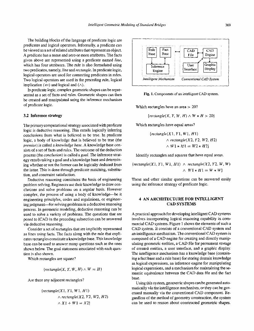
Fig. 1. Components of an intelligent CAD system.
Which rectangles have an area > 20?
{rectungZe(X, Y , W , H ) A W * H > 20)
Which rectangles have equal areas?
(rectungle(X1, Y 1 , W 1 , HI) A recfungle(X2, Y 2 , w 2 , H 2 ) A W 1 * H 1 = W 2 * H 2 )
Identify rectangles and squares that have equal areas.
{rectungle(Xl, Y1, W1, H I ) A rectungZe(X2, Y2 , W , W ) A W l * H l = W * W }
These and other similar questions can be answered easily using the inference strategy of predicate logic.
4 AN ARCHITECTURE FOR INTELLIGENT CAD SYSTEMS
A practical approach for developing intelligent CAD systems involves incorporating logical reasoning capability in com- mercial CAD systems. Figure 1 shows the elements of such a CAD system. It consists of a conventional CAD system and an intelligence mechanism. The conventional CAD system is composed of a CAD engine for creating and directly manip- ulating geometric entities, a CAD file for permanent storage of created entities, a user interface, and a graphic display. The intelligence mechanism has a knowledge base (contain- ing a fact base and a rule base) for storing domain knowledge as logical expressions, an inference engine for manipulating logical expressions, and a mechanism for maintaining the se- mantic equivalence between the CAD data file and the fact base.
Using this system, geometric shapes can be generated auto- matically via the intelligence mechanism, or they can be gen- erated manually via the conventional CAD component. Re- gardless of the method of geometry construction, the system can be used to reason about constructed geometric shapes.
370 Sivand Lakmazaheri
This is a very useful feature because it makes any geomet- ric model that can be imported into the system amenable to automated reasoning.
5 THE MECHANICS OF INTELLIGENT CAD
This section describes the mechanics of a logic-based intel- ligent CAD system. That is, it shows how geometric objects can be created and modified in a CAD system via logical deduction.
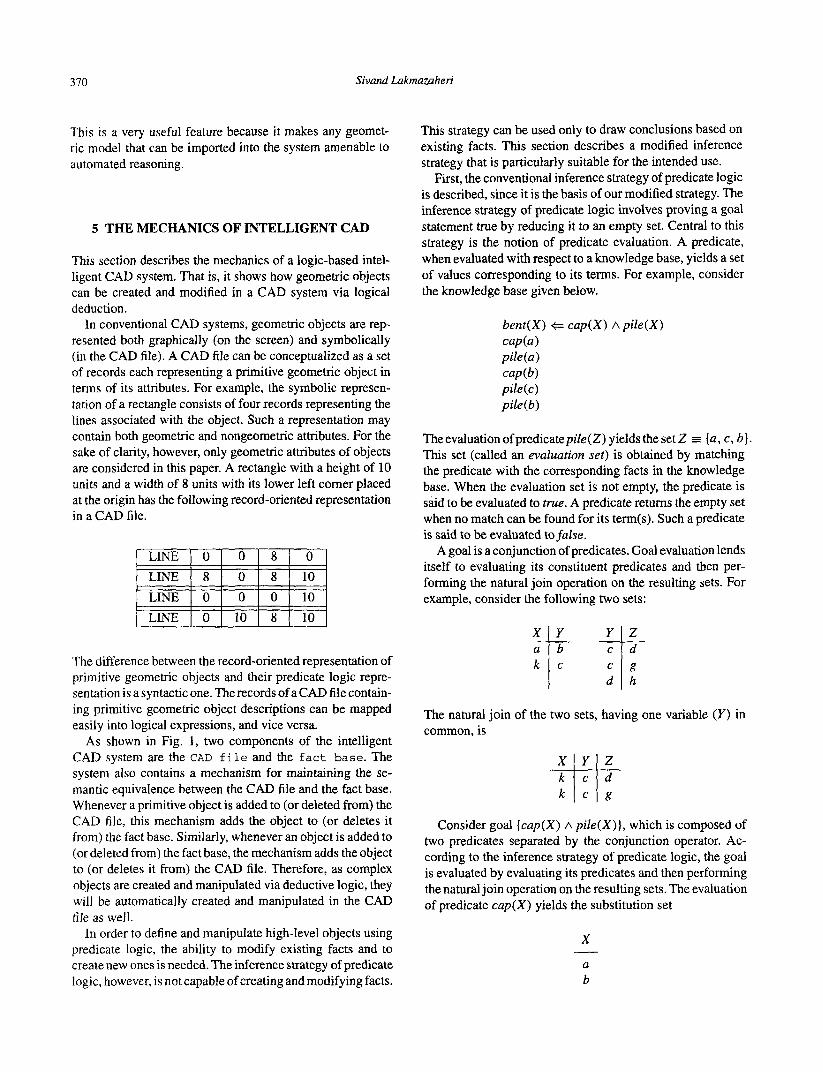
In conventional CAD systems, geometric objects are rep- resented both graphically (on the screen) and symbolically (in the CAD file). A CAD file can be conceptualized as a set of records each representing a primitive geometric object in terms of its attributes. For example, the symbolic represen- tation of a rectangle consists of four records representing the lines associated with the object. Such a representation may contain both geometric and nongeometric attributes. For the sake of clarity, however, only geometric attributes of objects are considered in this paper. A rectangle with a height of 10 units and a width of 8 units with its lower left comer placed at the origin has the following record-oriented representation in a CAD file.
The difference between the record-oriented representation of primitive geometric objects and their predicate logic repre- sentation is a syntactic one. The records of a CAD file contain- ing primitive geometric object descriptions can be mapped easily into logical expressions, and vice versa.
As shown in Fig. 1, two components of the intelligent CAD system are the CAD f i l e and the f a c t base. The system also contains a mechanism for maintaining the se- mantic equivalence between the CAD file and the fact base. Whenever a primitive object is added to (or deleted from) the CAD file, this mechanism adds the object to (or deletes it from) the fact base. Similarly, whenever an object is added to (or deleted from) the fact base, the mechanism adds the object to (or deletes it from) the CAD file. Therefore, as complex objects are created and manipulated via deductive logic, they will be automatically created and manipulated in the CAD file as well.
In order to define and manipulate high-level objects using predicate logic, the ability to modify existing facts and to create new ones is needed. The inference strategy of predicate logic, however, is not capable of creating and modifying facts.
This strategy can be used only to draw conclusions based on existing facts. This section describes a modified inference strategy that is particularly suitable for the intended use.
First, the conventional inference strategy of predicate logic is described, since it is the basis of our modified strategy. The inference strategy of predicate logic involves proving a goal statement true by reducing it to an empty set. Central to this strategy is the notion of predicate evaluation. A predicate, when evaluated with respect to a knowledge base, yields a set of values corresponding to its terms. For example, consider the knowledge base given below.
bent(X) + cup(X) ~ p i l e ( X ) caP(a> piZe(u) C U P @ ) pile(c) pile(b)
Theevaluationofpredicatepile(Z) yieldstheset 2 5 {a, c, b ] . This set (called an evaluation set) is obtained by matching the predicate with the corresponding facts in the knowledge base. When the evaluation set is not empty, the predicate is said to be evaluated to true. A predicate returns the empty set when no match can be found for its term(s). Such a predicate is said to be evaluated tofulse.
A goal is a conjunction of predicates. Goal evaluation lends itself to evaluating its constituent predicates and then per- forming the natural join operation on the resulting sets. For example, consider the following two sets: T-
d h
The natural join of the two sets, having one variable ( Y ) in common. is
Consider goal [cup(X) A p i l e (X) } , which is composed of two predicates separated by the conjunction operator. Ac- cording to the inference strategy of predicate logic, the goal is evaluated by evaluating its predicates and then performing the natural join operation on the resulting sets. The evaluation of predicate cup(X) yields the substitution set
X I_
U
b
Intelligent Geometric Modeling of Standard Bridges 37 1
The evaluation of predicate pile(X) yields the substitution set
X
a b
The natural join of these sets is
X
a b
-
c
-
When a predicate evaluates to true, it is removed from the goal. If the goal reduces to the empty set-if all the predicates are removed from the goal-then the goal is said to be proven true. The final substitution set gives the values for which the goal is true.
In the preceding example, goal reduction involves reducing the goal using facts only. Suppose a goal contains a predicate that does not appear as a fact but rather appears as the head of a rule. When such a predicate is encountered in the goal, it is replaced with the body of the rule. The body predicates are then processed in a similar manner until the goal contains only predicates that appear as facts in the knowledge base.
The standard inference strategy of predicate logic can only be used for determining the existence of objects in the knowl- edge base. The strategy can neither create nor modify ob- jects. Herein I describe a modified inference strategy that overcomes these limitations. In order to better describe the modified strategy, first the process of standard inference in predicate logic is illustrated by means of a simple example.
Consider the following declarative definition of a com- pound object CompoundA in terms of three primitive objects.
CompoundA(X) + CompoundB(X) A CompoundC(X) CompoundB(X) + Pr imitiveA(X) A Pr imitiveB(X) CompoundC(X) += Pr imitiveC(X) Pr imitiveA(a) Pr imitiveA (b ) Pr imitiveB(a) Pr inzitiveC(a) Pr imitiveC(c)
Suppose the truth of goal CompoundA(T) is to be deter- mined. This process is illustrated below:
{ CompoundA ( T ) }
First, the goal predicate is reduced using the first rule in the knowledge base:
{CompoundB(T) A CompoundC(T)}
The two predicates in the reduced goal are further reduced using the second and third rules:
{Pr imitiveA(T) A Pr imitiveB(T) A Pr imitiveC(T))
This reduced goal contains only base predicates. Each base predicate is evaluated, resulting in an evaluation set. Since each base predicate evaluates to true, it is removed from the goal. The resulting evaluation sets are then combined using the natural join operation. The evaluation of the first base predicate in the goal gives
{PrinzitiveB(T) A Pr imitiveC(T)} where T 3 {a , b]
The goal is further reduced to
{Pr imitiveC(T)) where T E {a )
The evaluation of the last goal predicate yields
{ 1 where T = { a }
The empty set indicates that the goal CompoundA(T) is proven true for T = a.
5.1 The modified inference strategy
The standard inference strategy of predicate logic is mod- ified by defining two metalogical operators called the truth enforcement and the falsity enforcement operator^.^ The truth enforcement operator enables the creation of new objects. The falsity enforcement operator enables object modifica- tions. These operators are described below.
5.1.1 The truth enforcement operator A knowledge base consists of a set of rules (representing compound object definitions) and a set of facts (representing primitive objects). The truth enforcement operator can be used to create a compound object by enforcing the truth of its definition.
Let the symbol “J-” denote the truth enforcement operator. Let {A A B A C) be a reduced goal where A, B , and C are base predicates. Enforcing the truth of a goal involves enforcing the truth of its underlying base predicates. Hence
4 { A A B A C ) = {J- A A J- B A J- C)
Enforcing the truth of a base predicate involves adding the base predicate to the knowledge base as a fact. This is done only if the knowledge base does not already contain the fact.
The processing of a goal subjected to the truth enforce- ment operator is as follows. First, the goal is reduced to a set of base predicates. Then, without being removed from the goal, the base predicates are evaluated and their evaluation sets are joined. Once the final evaluation set is obtained, the truth of each base predicate is enforced, and the base predi- cate is removed from the goal. The truth of the goal is said to be enforced when the empty set is reached. As an example, suppose object CompoundA(b) is to be created in the knowl- edge base. This is done using the truth enforcement operator
Sivand Lakmazaheri 312
as illustrated below:
4 { CompoundA ( b ) ] 4 {CompoundB(b) A CompoundC(b)] 4 {Pr imitiveA(b) A Pr imitiveB(b) A Pr irnitiveC(b)}
The base predicates in the reduced goal need not be evalu- ated because they contain no variables. Therefore, the truth enforcement operator is to be applied to each base predicate. That is,
(4 {Pr imitiveA(b)A 4 Pr imitiveB(b)A 4 Pr imitiveC(b))
The truth of the first base predicate is already enforced as a matching fact, for this base predicate exists in the knowledge base. Therefore, the base predicate is removed from the goal, yielding
(4 (PrirnitiveB(b)A 3. PrimitiveC(b))
Since Pr imitiveA (b) does not exist in the knowledge base, its truth is enforced by adding it to the knowledge base as a fact; the base predicate is then removed from the goal, resulting in
(4 Pr imitiveC(b)]
The truth of the remaining base predicate is enforced by adding it to the knowledge base as a fact. This reduces the goal to the empty set. The truth of the goal is enforced; the object is successfully added to the knowledge base. At this point, the knowledge base contains two additional facts. These are
Pr imitive B (b) Pr irnitiveC(b)
The addition of these facts completes the definition of object CompoundA(b) in the knowledge base.
5.1.2 The falsity enforcement operator This operator is used for removing compound objects from the knowledge base by enforcing the falsity of their defi- nitions. Let the symbol “f” denote the falsity enforcement operator. In order to enforce the falsity of a goal using this operator, the goal is first reduced to a set of base predicates. The operator is then applied to each base predicate, resulting in the enforcement of the negated base predicate. The appli- cation of the falsity enforcement operator is logically equiva- lent to the application of the truth enforcement operator to the negated goal. Consider goal { G } , which when reduced yields a conjunction of base predicates in the form ( A A B A C ) . When subjected to the falsity enforcement operator, the goal is expressed as f ( G ) or in its logically equivalent form as 4 - ( G ) . In the reducedform, this becomes 4 - { A A B A C ) . When the conjuncted predicates are negated, a disjunctive set of predicates results: { $ -Av 4 - B v 4 i C ] . In order to enforce the falsity of the original goal, it is sufficient to en- force the truth of only one the negated base predicates. The
truth of a negated predicate is enforced by removing all its matching facts from the knowledge base.
When a compound object is to be removed from the knowl- edge base, it is desirable to remove all its primitive compo- nents. Therefore, rather than applying the falsity enforcement operator to only one of the base predicates, the operator is applied to all the base predicates in the goal. Let us illustrate the application of the falsity enforcement operator by means of example.
Consider the original knowledge base given above. Sup- pose that it is desirable to remove object CompoundA (a). This is done by applying the falsity enforcement operator to the goal as illustrated below. First, the goal is reduced to a set of base predicates:
f (CompoundA(a)) f (CompoundB(a) A CompoundC(a)) f (Pr imitiveA { a ) A Pr imitiveB(a) A Pr imitiveC(a)]
The next step is to apply the falsity enforcement operator to the base predicates. That is,
(f Pr imitiveA(a)v f Pr imitiveB(a)v f PrimitiveC(a)]
The falsity of the goal is enforced by enforcing the falsity of the individual base predicates. The enforcement of the falsity of the first predicate results in removal of the fact Pr imitiveA(a) from the knowledge base. The enforcement of the falsity of the second predicate results in removal of the fact Pr irnitiveB(a) from the knowledge base. The enforcement of the falsity of the last predicate results in removal of the fact Pr imitiveC(a) from the knowledge base. By removing the relevant facts (primitive objects) from the knowledge base, complex objects are removed from the knowledge base.
The modification of complex objects can be achieved by first applying the falsity enforcement operator (to remove the existing object) and then applying the truth enforcement operator (to create the modified objects). The two operators provide a flexible means of creating and manipulating com- plex geometric objects deductively using the framework of predicate logic.
6 MODELING STANDARD BRIDGES
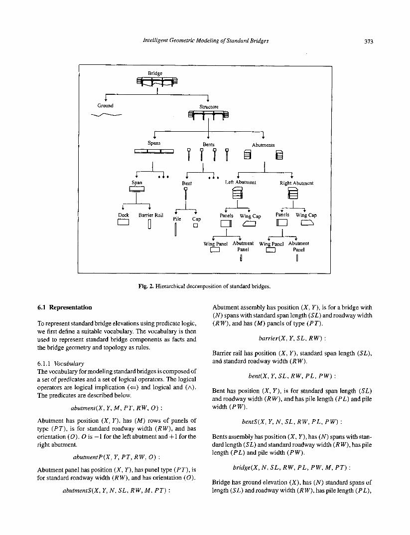
Herein we consider bridges that are composed of the follow- ing standard components: deck units, barrier rails, bent caps, abutment panels, wing panels, and wing caps (Fig. 2). Such standard bridges can be modeled using a set of facts that represent standard bridge components and a set of rules that represent the geometry and topology of standard bridges.
Figure 2 shows a hierarchical decomposition of standard bridges suitable for geometric modeling. To illustrate the for- mulation in details, the problem has been simplified by con- sidering the elevation of standard bridges only.
Intelligent Geometric Modeling of Standard Bridges 373
Bridge - I 1
Ground Structure - Bents Abutments spans
Span Bent Left Abutment Right Abutment a ia A m n
v Panels Wing cap Panels Wing Cap Deck 77 gamier Rail $4 A
Pile Cap 0
Fig. 2. Hierarchical decomposition of standard bridges.
6.1 Representation
To represent standard bridge elevations using predicate logic, we first define a suitable vocabulary. The vocabulary is then used to represent standard bridge components as facts and the bridge geometry and topology as rules.
6.1.1 Vocabulary The vocabulary for modeling standard bridges is composed of a set of predicates and a set of logical operators. The logical operators are logical implication (+=) and logical and (A).
The predicates are described below.
abutrnent(X, Y , M, P T , RW, 0 ) :
Abutment has position ( X , Y ) , has ( M ) rows of panels of type ( P T ) , is for standard roadway width ( R W ) , and has orientation (0). 0 is - 1 for the left abutment and + 1 for the right abutment.
abutmentP(X, Y , P T , RW, 0 ) :
Abutment panel has position (X, Y ) , has panel type ( P T ) , is for standard roadway width ( R W ) , and has orientation (0).
abutmentS(X, Y , N , S L , RW, M , P T )
Abutment assembly has position ( X , Y ) , is for a bridge with ( N ) spans with standard span length ( S L ) and roadway width ( R W ) , and has ( M ) panels of type ( P T ) .
barrier(X, Y , S L , R W ) :
Barrier rail has position ( X , Y ) , standard span length ( S L ) , and standard roadway width ( R W ) .
bent(X, Y, S L , RW, P L , P W ) :
Bent has position ( X , Y ) , is for standard span length (SL) and roadway width ( R W ) , and has pile length ( P L ) and pile width ( P W ) .
bentS(X, Y , N , S L , RW, P L , P W ) :
Bents assembly has position ( X , Y ) , has ( N ) spans with stan- dard length (SL) and standard roadway width ( R W ) , has pile length ( P L ) andpile width ( P W ) .
bridge(X, N , S L , RW, P L , P W , M , P T ) :
Bridge has ground elevation (X), has ( N ) standard spans of length ( S L ) and roadway width ( R W ) , has pile length ( P L ) ,
314 Sivand Lakmazaheri
and pile width ( P W ) , and has ( M ) rows of abutment panels of type ( P T ) .
cap(X, Y, SL, R W ) :
Bent cap has position ( X , Y ) and is for standard span length (SL) and roadway width ( R W ) .
deck(X, Y , SL , R W ) :
Deck has position ( X , Y ) , standard span length ( S L ) and standard roadway width ( R W ) .
ground([Sl, El, S2, E2, . . . I) :
Ground has pairs of station elevations ( S l , El), ( S 2 , E2),
line(X0, YO, X 1 , Y1) : . . .
Line has end coordinates ( X O , YO) and ( X l , Y 1).
lineString([XO, YO, X1, Y 1 , . . . I ) :
Line string has coordinates (XO, YO), (Xl , Y l ) , . . .
panelS(X, Y, M , P T , RW, 0 ) :
Panels assembly has position ( X , Y), has (M) rows of panels of type ( P T ) for standard roadway width ( R W ) , and has orientation (0).
pile(X, Y , P L , P W ) :
Pile has position ( X , Y), length ( P L ) , and width ( P W ) .
rectangle(X, Y, W , H) :
Rectangle has position ( X , Y), width ( W ) and height (H).
spun(X, Y, SL, R W ) :
Span has position (X, Y ) , standard span length ( S L ) , and standard roadway width ( R W ) .
spanS(X, Y , N , S L , R W ) :
Spans assembly has position (X, Y ) , ( N ) spans with standard span length ( S L ) and standard roadway width ( R W ) .
standardabutmenpanel(SL, RW, P T , W , H ) :
The abutment panel type ( P T ) for standard span length ( S L ) and standard roadway width ( R W ) has width ( W ) and height ( H ) .
standard-barrier-rail(SL, RW, H) : Standard barrier rail for span length ( S L ) and roadway width ( R W ) has height ( H ) .
standard-bent-cap(SL, R W , W , H) :
Standard bent cap for span length ( S L ) and roadway width ( R W ) has width ( W ) and height ( H ) .
standarddeck_unit(SL, RW, H) :
Standard deck unit for span length ( S L ) and roadway width ( R W ) has height (H).
standard-wing-cap(SL, RW, H1, H2, W1, W 2 ) :
Standard wing cap for span length ( S L ) and road way width ( R W ) has toe height (Hl), heel height (H2), base width ( W l ) and top width (W2).
standard-wingpanel(SL, RW, P T , W , H) :
The standard wing panel type ( P T ) for standard span length ( S L ) and roadway width ( R W ) has width ( W ) and height (HI.
structure(N, SL , R W , P L , P W , M , P T )
Structure has ( N ) spans of standard length ( S L ) and standard roadway width ( R W ) , has piles of length ( P L ) and width ( P W ) , and has abutments with ( M ) rows of panels of type ( P T ) .
wingC(X, Y , RW, 0 ) :
Wing cap has position ( X , Y ) , is for standard roadway width ( R W ) , and has orientation (0).
wingP(X, Y, P T , RW, 0) :
Wing panel has position ( X , Y) , standard panel type ( P T ) , is for standard roadway width ( R W ) , and has orientation (0).
6.1.2 Standard bridge components The formulation presented above focuses on the elevation of standard bridges. Therefore, we need to represent only the elevation-related geometric dimensions of standard deck units, barrier rails, bent caps, abutment and wing panels, and wing caps. These components exist for several standard span lengths and roadway widths. Several standard bridge compo- nents for span lengths 24 and 32 feet and roadway widths 26 and 28 feet are represented below.
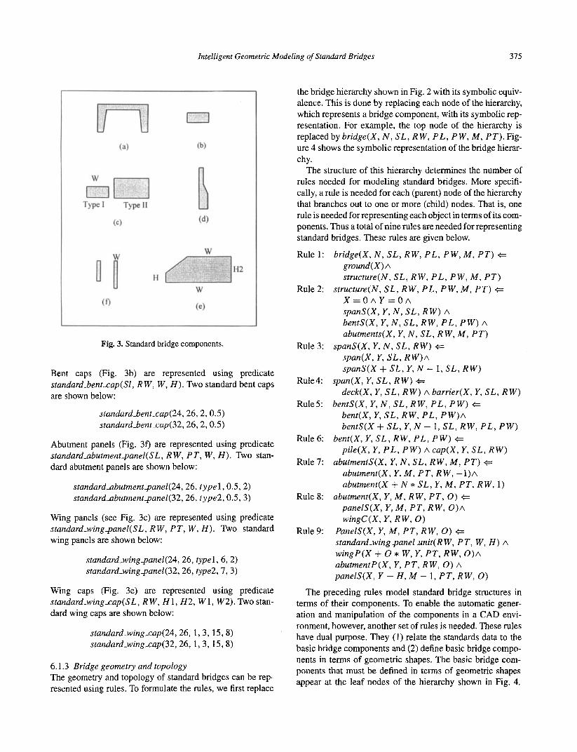
Deck units (Fig. 3a) are represented using predicate standard-deck-unit(SL, R W , H ) . Tho standard deck units are shown below.
standarddeckunit(24,26,2.0) standarddeck_unit(32,26,3.0)
Barrier rails (Fig. 3d) are represented using predicate standardbarrier-raiZ(SL, R W , H). Two standard barrier rails are shown below:
stundardbarrier_rai1(24,26,3.5) standardbarrier-rail(32,26,3.5)
Intelligent Geometric Modeling of Standard Bridges 375
Fig. 3. Standard bridge components.
Bent caps (Fig. 3b) are represented using predicate standardbent-cap(S1, R W , W , H ) . Two standard bent caps are shown below:
standardbent-cap(24, 26, 2,0.5) standardbent-cap(32,26,2,0.5)
Abutment panels (Fig. 3 f ) are represented using predicate standardabutmentpanel(SL, RW, P T , W , H ) . TWO stan- dard abutment panels are shown below:
standardabutmentpanel(24, 26, t ype l , 0.5, 2) standardabutmentpane1(32,26, type2,0.5,3)
Wing panels (see Fig. 3c) are represented using predicate standard-wingpanel(SL, R W , P T , W , H ) . Two standard wing panels are shown below:
standard_wingpanel(24,26, typel, 6, 2) standard-wingpanel(32,26, type2, 7 , 3)
Wing caps (Fig. 3e) are represented using predicate standard-wing-cap(SL, R W , H 1 , H2, W 1, W2). Two stan- dard wing caps are shown below:
standard-wing-cap(24,26, 1, 3, 15, 8) standard-wing-cap(32,26, 1,3, 15,8)
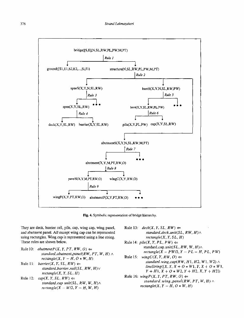
6.1.3 Bridge geometry and topology The geometry and topology of standard bridges can be rep- resented using rules. To formulate the rules, we first replace
the bridge hierarchy shown in Fig. 2 with its symbolic equiv- alence. This is done by replacing each node of the hierarchy, which represents a bridge component, with its symbolic rep- resentation. For example, the top node of the hierarchy is replacedbybridge(X, N , S L , RW, P L , P W , M , PT).Fig- ure 4 shows the symbolic representation of the bridge hierar- chy.
The structure of this hierarchy determines the number of rules needed for modeling standard bridges. More specifi- cally, a rule is needed for each (parent) node of the hierarchy that branches out to one or more (child) nodes. That is, one rule is needed forrepresenting each object in terms of its com- ponents. Thus a total of nine rules are needed for representing standard bridges. These rules are given below.
Rule 1 : bridge(X, N , S L , RW, P L , P W , M , P T ) e= ground( X ) A
structure(N, S L , R W , P L , P W , M , P T ) structure(N, S L , R W , P L , P W , M , P T ) +
X = O A Y = O r \ spanS(X, Y, N , S L , R W ) A bentS(X, Y , N , S L , R W , P L , P W ) A
abutments(X, Y , N , S L , R W , M , P T ) spanS(X, Y , N , S L , R W ) +=
span(X, Y , S L , R W ) A spanS(X + S L , Y , N - 1, S L , R W )
span(X, Y , S L , R W ) e= deck(X, Y , S L , R W ) A barrier(X, Y , S L , R W )
bentS(X, Y , N , S L , R W , P L , P W ) + bent(X, Y , S L , RW, P L , P W ) A bentS(X + S L , Y , N - I , S L , R W , P L , P W )
bent(X, Y , S L , RW, P L , P W ) + pile(X, Y , P L , P W ) A cap(X, Y , S L , R W )
abutmentS(X, Y , N , S L , R W , M , P T ) e abutrnent(X, Y , M , P T , R W , - 1 ) ~ abutment(X + N * S L , Y , M , P T , R W , 1 )
abutment(X, Y , M , R W , P T , 0 ) + panelS(X, Y , M , P T , R W , O ) A wingC(X, Y , R W , 0 )
PanelS(X, Y, M , P T , R W , 0 ) + standard-wingpanel-unit(R W , P T , W , H ) A wingP(X + 0 * W , Y , P T , R W , O ) A abutmentP(X, Y, P T , R W , 0 ) A panelS(X, Y - H , M - 1 , P T , R W , 0 )
The preceding rules model standard bridge structures in terms of their components. To enable the automatic gener- ation and manipulation of the components in a CAD envi- ronment, however, another set of rules is needed. These rules have dual purpose. They (1) relate the standards data to the basic bridge components and (2) define basic bridge compo- nents in terms of geometric shapes. The basic bridge com- ponents that must be defined in terms of geometric shapes appear at the leaf nodes of the hierarchy shown in Fig. 4.
Rule 2:
Rule 3:
Rule4:
Rule5:
Rule 6:
Rule 7:
Rule 8:
Rule 9:
376
Rule I
Sivand Lakmazaheri
Rule 2
+ spans( X,Y,N,SL,RW) 1 Rule 3
1 0 0 span(X,Y,SL,RW)
.t bentS(X,Y ,N,SL,RW,PW)
bent(X,Y ,SL,RW,PL,PW) Rule 6 4 1 Rule 4
pile(X,Y,PL,PW) c~P(X,Y,SL,RW) m
deck(X,Y,SL,RW) barrier(X,Y,SL,RW)
abutmentS(X,Y,N,SL,RW,M,PT)
I Rule 7
I 1 0 . .
abutment( X,Y ,M,PT,R W,O) I Rule 8
1 1 panelS(X,Y,M,PT,RW,O) wingC(X,Y,RW,O)
1 Rule 9
Fig. 4. Symbolic representation of bridge hierarchy.
They are deck, bamer rail, pile, cap, wing cap, wing panel, and abutment panel. All except wing cap can be represented using rectangles. Wing cap is represented using a line string. These rules are shown below.
Rule 10:
Rule 13: deck(X, Y , S L , R W ) -i=
standarddeck-unit(S1, R W , H ) A rectangle(X, Y , S L , H )
Rule 14: p i l e ( X , Y , P L , P W ) e= standard-cap-unit(SL, RW, W , H ) A rectangle(X - PWl2, Y - P L - H , P L , P W )
standard-wing-cap(RW, H1, H2, W1, W 2 ) h lineString([X, Y , X + 0 * W1, Y , X + 0 * W 1 , Y + H1,X + 0 * W 2 , Y + H2, X , Y + H21)
abutmentP(X, Y , P T , R W , 0 ) .+ standardabutmentpanel(R W , P T , W , H ) A
rectangle(X, Y - H , 0 * W , H )
standarddarrier..rail(SL, R W , H ) v rectangle(X, Y , S L , H)
standard-cap-unit(S1, R W , W , H ) A rectangle(X - Wl2, Y - H , W , H )
Rule 15: wingC(X, Y , RW, 0 ) -+ Rule 1 1 : barrier(X, Y , S L , R W ) -+
Rule 16: wingP(X, Y , P T , R W , 0 ) -+ Rule 12: cap(X, Y , S L , R W ) + standard-wing-panel(RW, P T , W , H ) A
rectangle(X, Y - H , 0 * W , H )
Intelligent Geometric Modeling of Standard Bridges 377
Rules 1 through 16 model standard bridges in terms of rectangles and line strings. Suppose the CAD system can only create and manipulate lines. To accommodate this limitation, we define rectangles and line strings in terms of lines. This can be done using the following two rules.
Rule 17: rectangle(X, Y, W, H ) -+ line(X, Y, x + w, Y)A h ? ( X + w, Y, x + w, Y + H) A
line(X, Y, X , Y + H ) A Zine(X, Y + H , X + W, Y + H)
lineString([XO, YO, X 1 , Y l , . . . I) (5
l ine(X0, YO, X1, Y1)A LineString( [ X 1, Y 1, . . . I )
Rule 18:
The preceding rules define bridge components (compound objects) in terms of lines (primitive objects). Lines are stored as facts in the knowledge base. These rules and facts con- stitute the knowledge base. This knowledge base is self- contained, and it can be used to create and manipulate stan- dard bridges, as demonstrated in the next subsection.
6.2 Manipulation
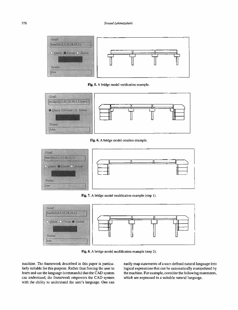
This subsection illustrates the power of intelligent CAD by means of examples. Consider a conventional CAD system that is equipped with the intelligence mechanism. In this sys- tem the user interacts with the intelligence mechanism via a dialog box. This dialog box enables the user to specify goals for creating and deleting bridge components as well as re- trieving information about the bridge model. As shown in Figs. 5 through 8, the dialog box contains a text field for en- tering goal statements, three option buttons for choosing the mode of goal processing, a pushbutton for initiating goal exe- cution, and a text field for displaying messages received from the intelligence mechanism. The modes of goal processing are create, delete, and query. In the create mode, the intel- ligence mechanism creates the bridge or bridge components that are described by the goal. In the delete mode, the intel- ligence mechanism deletes the bridge or bridge components that are described by the goal. In the query mode, the intel- ligence mechanism returns the information that is requested by the goal statement.
Example 1 Suppose the user has partially defined a bridge geometry using the conventional CAD component. The objective is to determine whether or not the bridge geometry adheres to the bridge definition contained in the knowledge base.
This objective can be achieved by formulating a goal that completely describes the bridge and by processing the goal in the query mode. The result of processing this query is a simple true or false. If the defined geometry adheres to the bridge definition, then the result is true. Otherwise, the result is false.
The defined geometry (shown in Fig. 5 ) is an incomplete representation of a standard bridge, since the abutments are missing from the model. Therefore, the result of processing the goal in the query mode isfalse.
Examp Le 2 Consider the incomplete bridge geometry used in Example 1. Suppose the objective is to complete the bridge geometry without redrawing the partial model. This can be done by processing the goal in the create mode, as depicted in Fig. 6.
When a goal is processed in the create mode, it causes the creation of the geometry of interest. If a part of the geometry already exists, the goal processing results in the generation of the remaining parts. Otherwise, the whole geometry is generated. The ability to process partial models is particularly useful in practice because it allows bridge models that are created by another CAD system to be verified and completed by the intelligent CAD system.
Example 3 Consider the completed bridge model given in the preceding example. Suppose pile length is to be changed from 10 to 12 feet. This can be done by first deleting the existing piles and then creating the new ones. To delete the piles, query bentS(O,O, 3,32,28, 10, I ) is processed in the delete mode. This results in the removal of all the bents, as shown in Fig. 7. Then, query bentS(0, 0, 3,32,28, 12, 1) is processed in the create mode. As a result, the bridge bents are redrawn using the new pile length, as shown in Fig. 8.
7 DISCUSSION
A framework for developing intelligent CAD systems and its use for modeling the geometry of standard bridges was il- lustrated. The framework involves empowering conventional CAD systems with deductive reasoning capability using pred- icate logic.
Geometric modeling involves mapping the user’s percep- tion of a physical system into its graphic representation. This mapping is a complex task, since the user has to decompose the system into primitive geometric entities and then use the entities to construct the graphic representation of the system. In addition to being time-consuming, this mapping process is error-prone, since the mapping has to be done mentally by the user. This mapping can be automated if the user’s perception of a physical system can be explicated and formally repre- sented. Predicate logic is the ideal tool for this purpose. It can be used to declaratively represent physical systems in terms of objects and relations. This representation is amenable to automatic manipulation and thus can be used for automati- cally generating the geometry of the system.
One of the goals of advanced computing research is to remove communication barriers between the user and the
378 Sivand Lakmazaheri
Fig. 5. A bridge model verification example.
Fig. 6. A bridge model creation example.
Fig. 7. A bridge model modification example (step 1).
Fig. 8. A bridge model modification example (step 2).
machine. The framework described in this paper is particu- larly suitable for this purpose. Rather than forcing the user to learn and use the language (commands) that the CAD system can understand, the framework empowers the CAD system with the ability to understand the user’s language. One can
easily map statements of a user-defined natural language into logical expressions that can be automatically manipulated by the machine. For example, consider the following statements, which are expressed in a suitable natural language.
Intelligent Geometric Modeling of Standard Bridges 379
A node has position x and y. A line has i node and j node. A rectangle has position and width and height. Rectangle con- sists of a lejl line, a top line, a right line, and a bottom line where . . .
These statements define rectangle in terns of line and point. The statements can be mapped automatically into the pred- icate logic definition of rectangle, which then can be used to automatically generate rectangles. In this way, geometric modeling reduces to the task of expressing one’s perception of physical systems in a suitable natural language. Everything else is handled by the machine.
The computational power of intelligent CAD systems sur- passes that of conventional CAD systems. The primary ca- pability of conventional CAD systems is to create geometric models. The correctness of such models cannot be verified in the conventional framework. Furthermore, these systems do not have query-answering capabilities. Intelligent CAD systems embody a mechanism that enables model creation, modification, and verification. The mechanism also can be used as an information retrieval means for providing answers to users’ queries.
REFERENCES
1. Arbab, F., A paradigm for intelligent CAD. In Intelligent CAD
2. Backstrom, C., Logical modeling of simplified geometrical ob- Systems I , Springer-Verlag, New York, 1987, pp. 20-39.
jects and mechanical assembly processes. In Advances in Spa- tial Reasoning, vol. 1, ed. by s. Chen, Ablex Publishing, Nor- wood, NJ, 1990, pp. 35-62.
3. Berkhout, E. E., Methodology of intelligent CAD systems. In Intelligent CAD Systems I , Springer-Verlag, New York, 1987,
4. Bijl, A., Strategies for CAD. In Intelligent CAD Systems I , Springer-Verlag, New York, 1987, pp. 2-19.
5. Lakmazahen, S . A logic-based mechanism for integrity main- tenance of engineering databases, Engineering with Computers 11 (1) (1995), 46-57.
6. Ohsuga, S., Toward intelligent CAD systems, Computer Aided Design, 21 ( 5 ) (1989), 315-337.
7. Pineda, L. & Klein, E., A graphical and logical language for a simple design domain. In Intelligent CAD Systems III, Springer- Verlag, New York, 1991, pp. 103-130.
8. Sunde, G., A CAD system with declarative specifications of shapes. In Intelligent CAD Systems I . Springer-Verlag, New York, 1987, pp. 90-104.
9. Tomiyama, T. &ten Hagen, P. J. W., Representing knowledge in two distinct descriptions: Extensional vs intensional, Artificial Intelligence in Engineering 5 (1) (1990), 23-32.
10. Treur, J., A logical framework for design processes. In Intelli- gent CAD Systems III, Springer-Verlag, New York, 1991, pp.
11. Veth, B., An integrated data description language for coding de- sign knowledge. In Intelligent CAD Systems I , Springer-Verlag, New York, 1987, pp. 295-313.
12. Yagiu, T., A predicate-logical method for modelling design ob- jects,Art$cial Intelligence in Engineering, 4 (1) (1989), 41-53.
pp. 105-122.
3-19.