Embed Size (px)
Citation preview
i
GypLyner universal Internal wall insulation (IWI) installation guide
1
GypLyner universalInternal wall insulation
Pre-Installation survey requirements
It is important to note that the survey should be carried out by a competent person as defined within the relevant annex within PAS 2030.
Guidance checks as a minimum should include:
— Making notes of any pre-existing damage to the ar eas that will be accessed by the installation operatives
— Assessing the extent of the area and elements to be insulated
— Whether relevant checks have been undertaken to determine if asbestos-containing materials are present
— Check to see if relevant arrangements have been made for the isolation and, where necessary, the temporary removal of existing services (gas, electric, water, telephone, etc.)
— Carry out checks to ensure there is no dampness or condensation / mould growth issues which would affect a lining system being installed
— Check to make sure all existing ventilation outlets can be maintained through to the new lining system that is installed
— Ensure assessments are made regarding the work carried out
• Will not compromise Building Regulations inrelation to workmanship, materials, fire safetyand ventilation
• Will not compromise the functionality and / orsafety of existing services
— Check the condition of the floor structure and sub-floor void is suitable for the works to commence in relation to:
• Existence of appropriate floor void ventilationarrangements
• The under floor area being free fromrodents / pests
• Timbers free from rot and / or infestation
• Metal structural floor support members beingfree from visible signs of corrosion
• Electrical wiring is free from visible defects,e.g. damaged cables, trailing cables, exposedconductors
• No visible signs of water penetration or wateraccumulation in the under floor area
• No visible signs of leakage from water systemcomponents e.g. pipework
It is important to carry out a detailed close inspection to the internal wall surface to identify any dampness issues and to ascertain whether the property has a damp-proof course (DPC), this will be dependent on the age of the property. It is worth asking the homeowner if the property has had a DPC injection treatment while they have been in the property, or if it was identified through the property survey when it was purchased. Where a DPC is identified, the condition should be checked as well as the distance of the floor level to the position of the DPC.
Carrying out a close inspection of the external of the property should be carried out to check for leaking gutters, downspouts, missing flashings, deteriorating brickwork and / or mortar joints, as these are common problems which can result in penetrating dampness.
2
Introduction
The purpose of this guide is to define and show the installation process for GypLyner universal; this is one of the British Gypsum BBA-certified internal wall insulation systems which can be used to improve the energy efficiency measures within buildings and is used in relation to PAS 2030 for quality management purposes.
While the construction methods for each wall lining system will vary, there is generic information which is deemed best practice irrespective of which system is installed; this covers minimising air leakage, reducing thermal bridging, accommodating fixtures of cupboards, radiators, curtain track, etc.
Under Building Regulations, Part L 1B there is a requirement for upgrading existing properties to an improved U value of 0.3 where the footprint of each room allows. Depending on which lining system is installed, it is important to have a U-value and dew point calculation carried out to ensure the wall construction and new lining system do not create risks of harmful condensation within the wall fabric and that the new level of insulation is met.
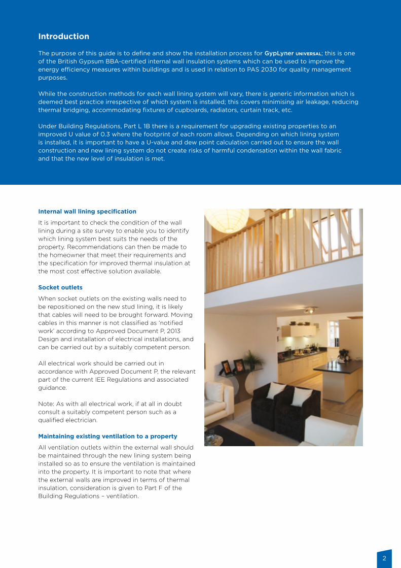
Internal wall lining specification
It is important to check the condition of the wall lining during a site survey to enable you to identify which lining system best suits the needs of the property. Recommendations can then be made to the homeowner that meet their requirements and the specification for improved thermal insulation at the most cost effective solution available.
Socket outlets
When socket outlets on the existing walls need to be repositioned on the new stud lining, it is likely that cables will need to be brought forward. Moving cables in this manner is not classified as ‘notified work’ according to Approved Document P, 2013 Design and installation of electrical installations, and can be carried out by a suitably competent person. All electrical work should be carried out in accordance with Approved Document P, the relevant part of the current IEE Regulations and associated guidance. Note: As with all electrical work, if at all in doubt consult a suitably competent person such as a qualified electrician.
Maintaining existing ventilation to a property
All ventilation outlets within the external wall should be maintained through the new lining system being installed so as to ensure the ventilation is maintained into the property. It is important to note that where the external walls are improved in terms of thermal insulation, consideration is given to Part F of the Building Regulations – ventilation.
3
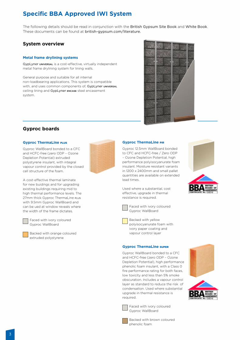
System overview
Metal frame drylining systems
GypLyner universal is a cost-effective, virtually independentmetal frame drylining system for lining walls.
General purpose and suitable for all internal non-loadbearing applications. This system is compatible with, and uses common components of, GypLyner universal ceiling lining and GypLyner encase steel encasement system.
Gyproc boards
Gyproc ThermaLine plus
Gyproc WallBoard bonded to a CFC and HCFC-free (zero ODP – Ozone Depletion Potential) extruded polystyrene insulant, with integral vapour control provided by the closed cell structure of the foam.
A cost-effective thermal laminate for new buidings and for upgrading existing buildings requiring mid to high thermal performance levels. The 27mm thick Gyproc ThermaLine plus with 9.5mm Gyproc WallBoard and can be ued at window reveals where the width of the frame dictates.
Faced with ivory coloured Gyproc WallBoard
Backed with orange coloured extruded polystyrene
Gyproc ThermaLine pir
Gyproc 12.5mm WallBoard bonded to CFC and HCFC-free / Zero ODP – Ozone Depletion Potential, high performance polyisocyanurate foam insulant. Moisture resistant variants in 1200 x 2400mm and small pallet quantities are available on extended lead times.
Used where a substantial, cost effective, upgrade in thermal resistance is required.
Faced with ivory coloured Gyproc WallBoard
Backed with yellow polyisocyanurate foam with ivory paper coating and vapour control layer
Gyproc ThermaLine super
Gyproc WallBoard bonded to a CFC and HCFC-free (zero ODP – Ozone Depletion Potential), high performance phenolic foam insulant, with a Class 0 fire performance rating for both faces, low toxicity and less than 5% smoke obscuration. Includes a vapour control layer as standard to reduce the risk of condensation. Used where substantial upgrade in thermal resistance is required.
Faced with ivory coloured Gyproc WallBoard
Backed with brown coloured phenolic foam
Specific BBA Approved IWI System
The following details should be read in conjunction with the British Gypsum Site Book and White Book. These documents can be found at british-gypsum.com/literature.
4
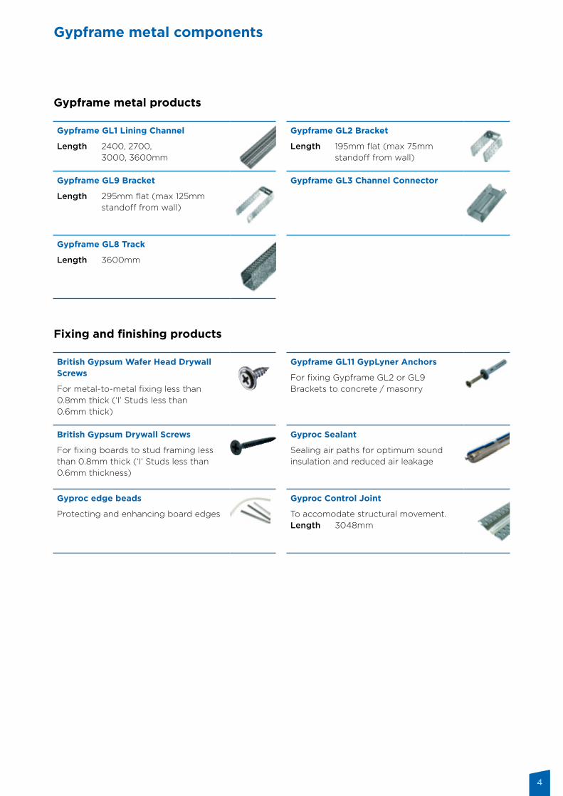
Gypframe metal products
Fixing and finishing products
Gypframe metal components
Gypframe GL1 Lining Channel
Length 2400, 2700, 3000, 3600mm
Gypframe GL2 Bracket
Length 195mm flat (max 75mm standoff from wall)
Gypframe GL9 Bracket
Length 295mm flat (max 125mm standoff from wall)
Gypframe GL3 Channel Connector
Gypframe GL8 Track
Length 3600mm
British Gypsum Wafer Head Drywall Screws
For metal-to-metal fixing less than 0.8mm thick (‘I’ Studs less than 0.6mm thick)
Gypframe GL11 GypLyner Anchors
For fixing Gypframe GL2 or GL9 Brackets to concrete / masonry
British Gypsum Drywall Screws
For fixing boards to stud framing less than 0.8mm thick (‘I’ Studs less than 0.6mm thickness)
Gyproc Sealant
Sealing air paths for optimum sound insulation and reduced air leakage
Gyproc edge beads
Protecting and enhancing board edges
Gyproc Control Joint
To accomodate structural movement.Length 3048mm
5
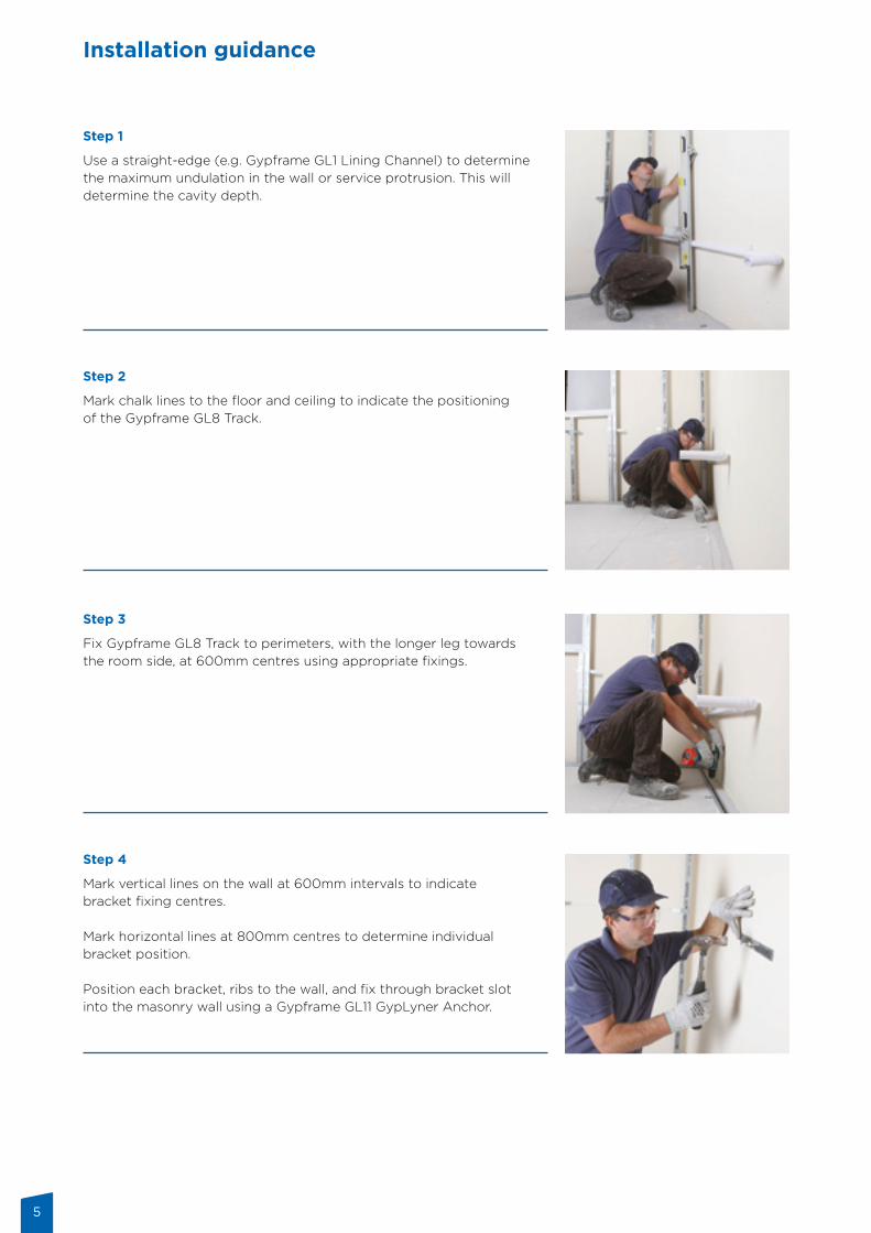
Step 1
Use a straight-edge (e.g. Gypframe GL1 Lining Channel) to determine the maximum undulation in the wall or service protrusion. This will determine the cavity depth.
Step 2
Mark chalk lines to the floor and ceiling to indicate the positioning of the Gypframe GL8 Track.
Step 3
Fix Gypframe GL8 Track to perimeters, with the longer leg towards the room side, at 600mm centres using appropriate fixings.
Step 4
Mark vertical lines on the wall at 600mm intervals to indicate bracket fixing centres.
Mark horizontal lines at 800mm centres to determine individual bracket position.
Position each bracket, ribs to the wall, and fix through bracket slot into the masonry wall using a Gypframe GL11 GypLyner Anchor.
Installation guidance
6
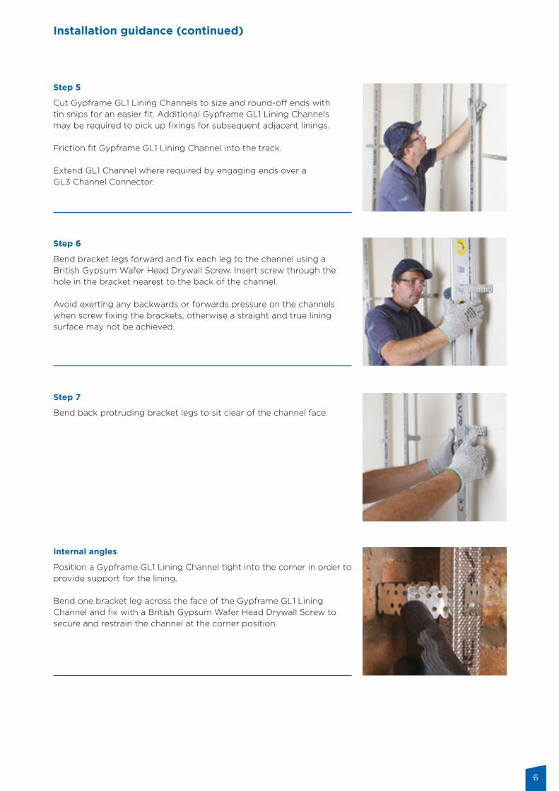
Step 5
Cut Gypframe GL1 Lining Channels to size and round-off ends with tin snips for an easier fit. Additional Gypframe GL1 Lining Channels may be required to pick up fixings for subsequent adjacent linings.
Friction fit Gypframe GL1 Lining Channel into the track.
Extend GL1 Channel where required by engaging ends over a GL3 Channel Connector.
Step 7
Bend back protruding bracket legs to sit clear of the channel face.
Internal angles
Position a Gypframe GL1 Lining Channel tight into the corner in order to provide support for the lining.
Bend one bracket leg across the face of the Gypframe GL1 Lining Channel and fix with a British Gypsum Wafer Head Drywall Screw to secure and restrain the channel at the corner position.
Step 6
Bend bracket legs forward and fix each leg to the channel using aBritish Gypsum Wafer Head Drywall Screw. Insert screw through the hole in the bracket nearest to the back of the channel.
Avoid exerting any backwards or forwards pressure on the channels when screw fixing the brackets, otherwise a straight and true lining surface may not be achieved.
Installation guidance (continued)
7
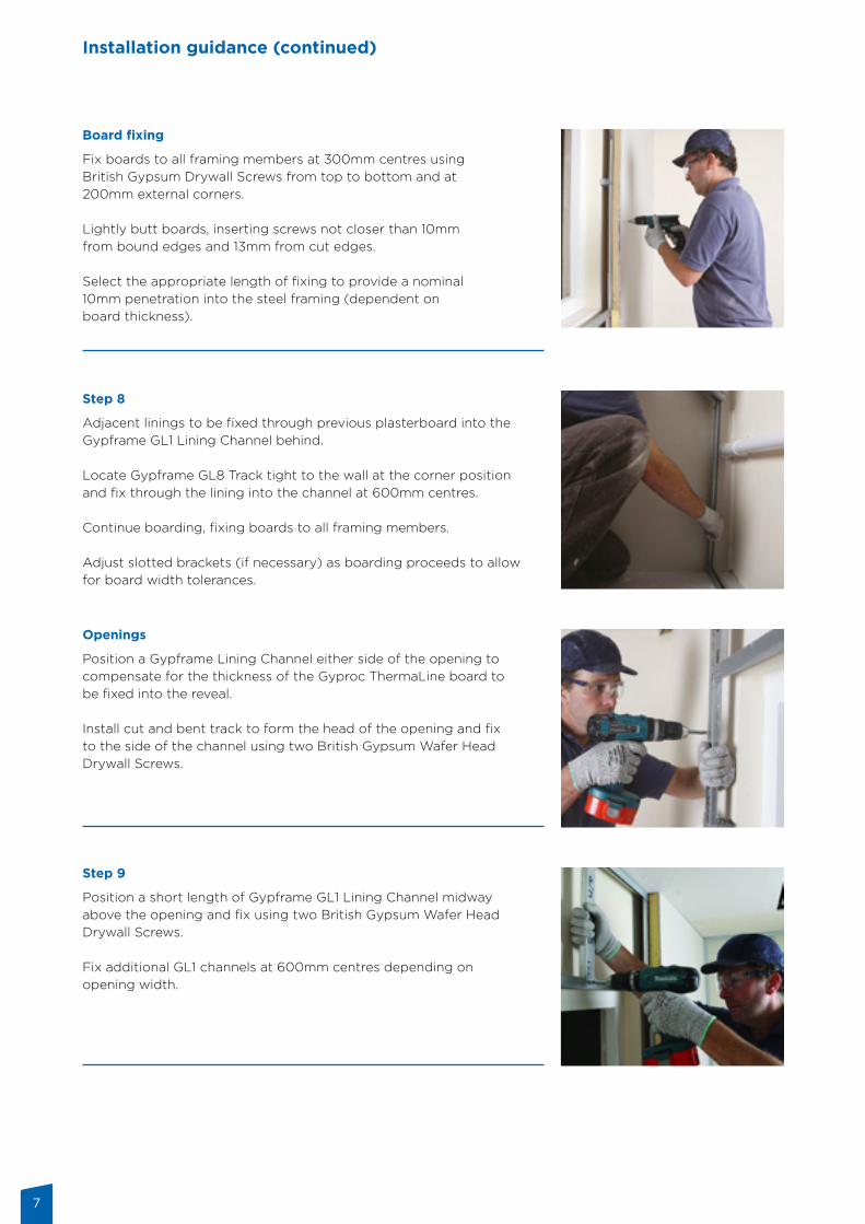
Board fixing
Fix boards to all framing members at 300mm centres usingBritish Gypsum Drywall Screws from top to bottom and at 200mm external corners.
Lightly butt boards, inserting screws not closer than 10mmfrom bound edges and 13mm from cut edges.
Select the appropriate length of fixing to provide a nominal10mm penetration into the steel framing (dependent onboard thickness).
Openings
Position a Gypframe Lining Channel either side of the opening to compensate for the thickness of the Gyproc ThermaLine board to be fixed into the reveal.
Install cut and bent track to form the head of the opening and fix to the side of the channel using two British Gypsum Wafer Head Drywall Screws.
Step 9
Position a short length of Gypframe GL1 Lining Channel midway above the opening and fix using two British Gypsum Wafer Head Drywall Screws.
Fix additional GL1 channels at 600mm centres depending on opening width.
Step 8
Adjacent linings to be fixed through previous plasterboard into theGypframe GL1 Lining Channel behind.
Locate Gypframe GL8 Track tight to the wall at the corner positionand fix through the lining into the channel at 600mm centres.
Continue boarding, fixing boards to all framing members.
Adjust slotted brackets (if necessary) as boarding proceeds to allowfor board width tolerances.
Installation guidance (continued)
8
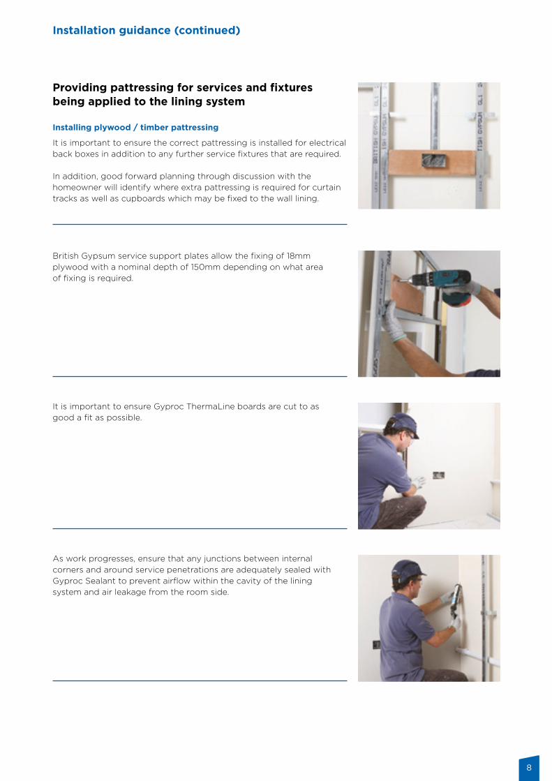
Providing pattressing for services and fixtures being applied to the lining system
Installing plywood / timber pattressing
It is important to ensure the correct pattressing is installed for electrical back boxes in addition to any further service fixtures that are required.
In addition, good forward planning through discussion with the homeowner will identify where extra pattressing is required for curtain tracks as well as cupboards which may be fixed to the wall lining.
It is important to ensure Gyproc ThermaLine boards are cut to as good a fit as possible.
As work progresses, ensure that any junctions between internal corners and around service penetrations are adequately sealed with Gyproc Sealant to prevent airflow within the cavity of the lining system and air leakage from the room side.
British Gypsum service support plates allow the fixing of 18mm plywood with a nominal depth of 150mm depending on what area of fixing is required.
Installation guidance (continued)
9
Installation guidance (continued)
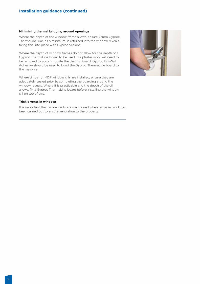
Minimising thermal bridging around openings
Where the depth of the window frame allows, ensure 27mm Gyproc ThermaLine plus, as a minimum, is returned into the window reveals, fixing this into place with Gyproc Sealant.
Where the depth of window frames do not allow for the depth of a Gyproc ThermaLine board to be used, the plaster work will need to be removed to accommodate the thermal board. Gyproc Dri-Wall Adhesive should be used to bond the Gyproc ThermaLine board to the masonry.
Where timber or MDF window cills are installed, ensure they are adequately sealed prior to completing the boarding around the window reveals. Where it is practicable and the depth of the cill allows, fix a Gyproc ThermaLine board before installing the window cill on top of this.
Trickle vents in windows
It is important that trickle vents are maintained when remedial work has been carried out to ensure ventilation to the property.
10
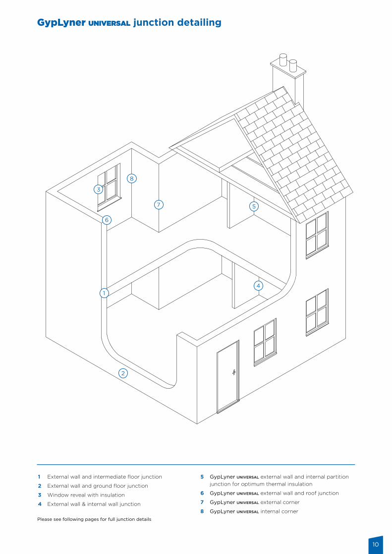
1 External wall and intermediate floor junction
2 External wall and ground floor junction
3 Window reveal with insulation
4 External wall & internal wall junction
5 GypLyner universal external wall and internal partition junction for optimum thermal insulation
6 GypLyner universal external wall and roof junction
7 GypLyner universal external corner
8 GypLyner universal internal corner Please see following pages for full junction details
GypLyner universal junction detailing
11
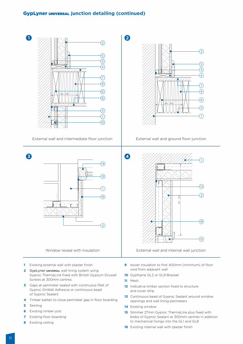
External wall and intermediate floor junction External wall and ground floor junction
Window reveal with insulation External wall and internal wall junction
1 Existing external wall with plaster finish
2 GypLyner universal wall lining system using Gyproc ThermaLine fixed with British Gypsum Drywall Screws at 300mm centres.
3 Gaps at perimeter sealed with continuous fillet of Gyproc DriWall Adhesive or continuous bead of Gyproc Sealant
4 Timber batten to close perimeter gap in floor boarding
5 Skirting
6 Existing timber joist
7 Existing floor boarding
8 Existing ceiling
9 Isover insulation to first 400mm (minimum) of floor void from adjacent wall
10 Gypframe GL2 or GL9 Bracket
11 Mesh
12 Indicative timber section fixed to structure and cover strip
13 Continuous bead of Gyproc Sealant around window openings and wall lining perimeters
14 Existing window
15 Slimmer 27mm Gyproc ThermaLine plus fixed with blobs of Gyproc Sealant at 300mm centres in addition to mechanical fixings into the GL1 and GL8
16 Existing internal wall with plaster finish
GypLyner universal junction detailing (continued)
12
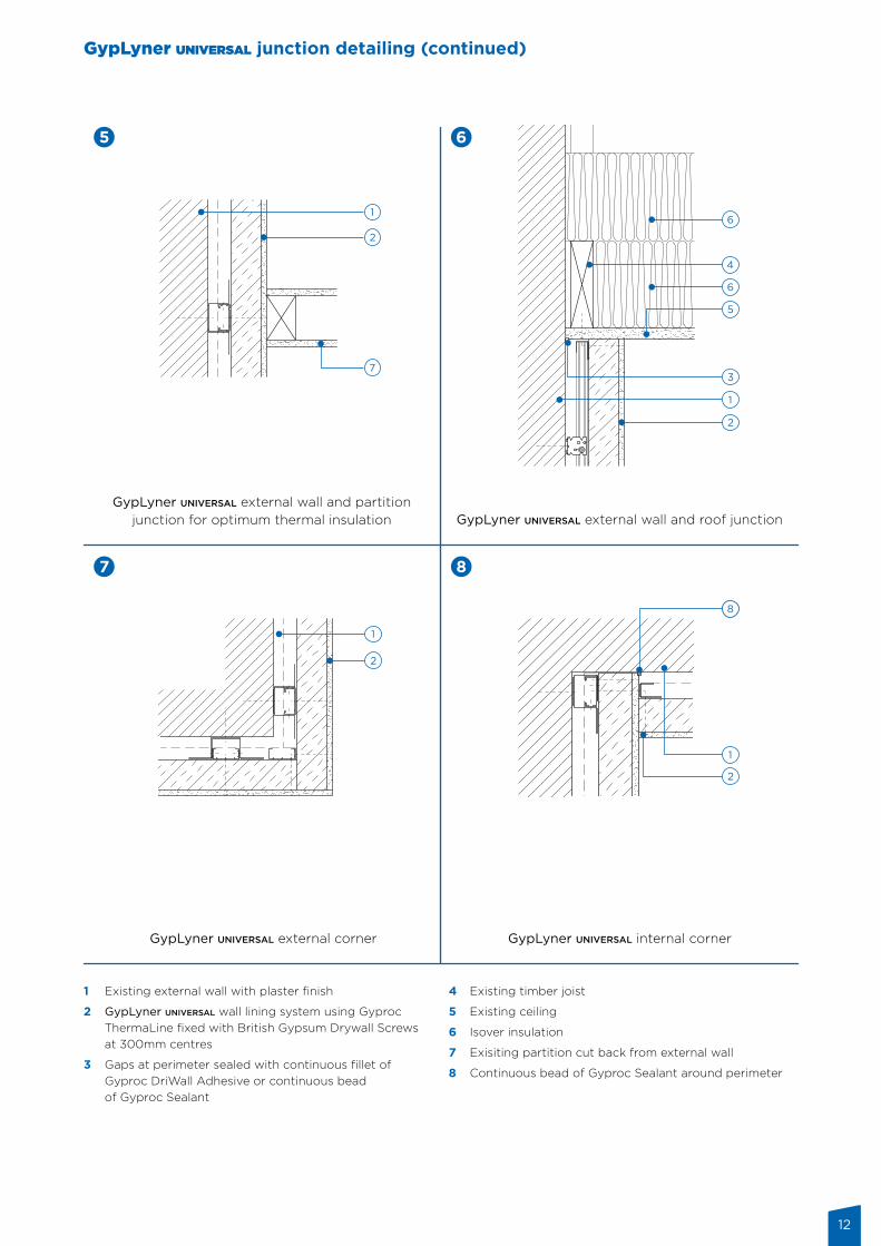
GypLyner universal external wall and partition junction for optimum thermal insulation GypLyner universal external wall and roof junction
GypLyner universal external corner GypLyner universal internal corner
1 Existing external wall with plaster finish
2 GypLyner universal wall lining system using Gyproc ThermaLine fixed with British Gypsum Drywall Screws at 300mm centres
3 Gaps at perimeter sealed with continuous fillet of Gyproc DriWall Adhesive or continuous bead of Gyproc Sealant
4 Existing timber joist
5 Existing ceiling
6 Isover insulation
7 Exisiting partition cut back from external wall
8 Continuous bead of Gyproc Sealant around perimeter
GypLyner universal junction detailing (continued)
13
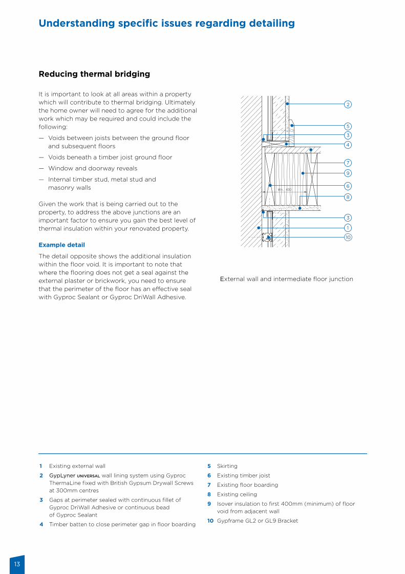
Reducing thermal bridging It is important to look at all areas within a property which will contribute to thermal bridging. Ultimately the home owner will need to agree for the additional work which may be required and could include the following:
— Voids between joists between the ground floor and subsequent floors
— Voids beneath a timber joist ground floor
— Window and doorway reveals
— Internal timber stud, metal stud and masonry walls
Given the work that is being carried out to the property, to address the above junctions are an important factor to ensure you gain the best level of thermal insulation within your renovated property.
Example detail
The detail opposite shows the additional insulation within the floor void. It is important to note that where the flooring does not get a seal against the external plaster or brickwork, you need to ensure that the perimeter of the floor has an effective seal with Gyproc Sealant or Gyproc DriWall Adhesive.
External wall and intermediate floor junction
Understanding specific issues regarding detailing
1 Existing external wall
2 GypLyner universal wall lining system using Gyproc ThermaLine fixed with British Gypsum Drywall Screws at 300mm centres
3 Gaps at perimeter sealed with continuous fillet of Gyproc DriWall Adhesive or continuous bead of Gyproc Sealant
4 Timber batten to close perimeter gap in floor boarding
5 Skirting
6 Existing timber joist
7 Existing floor boarding
8 Existing ceiling
9 Isover insulation to first 400mm (minimum) of floor void from adjacent wall
10 Gypframe GL2 or GL9 Bracket
14
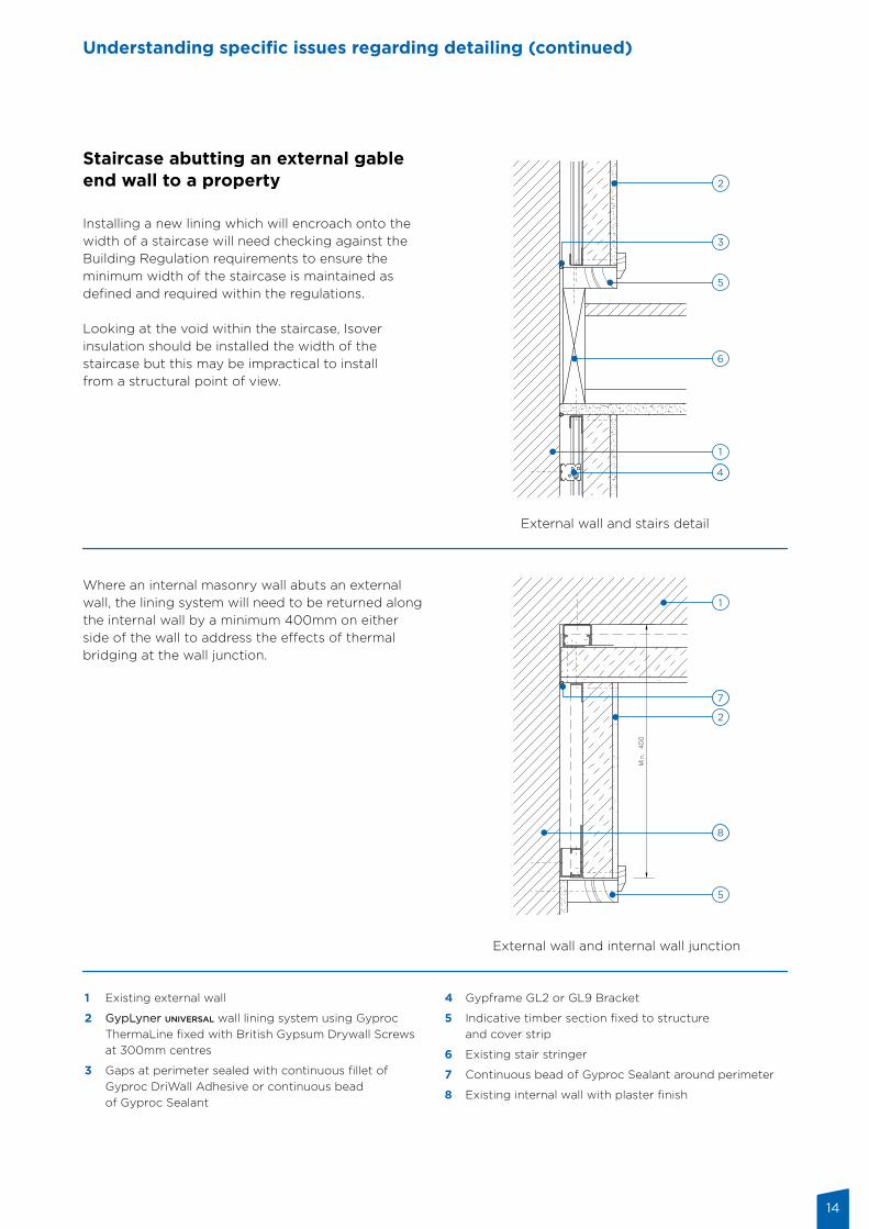
Staircase abutting an external gable end wall to a property Installing a new lining which will encroach onto the width of a staircase will need checking against the Building Regulation requirements to ensure the minimum width of the staircase is maintained as defined and required within the regulations.
Looking at the void within the staircase, Isover insulation should be installed the width of the staircase but this may be impractical to install from a structural point of view.
Where an internal masonry wall abuts an external wall, the lining system will need to be returned along the internal wall by a minimum 400mm on either side of the wall to address the effects of thermal bridging at the wall junction.
External wall and stairs detail
External wall and internal wall junction
Understanding specific issues regarding detailing (continued)
1 Existing external wall
2 GypLyner universal wall lining system using Gyproc ThermaLine fixed with British Gypsum Drywall Screws at 300mm centres
3 Gaps at perimeter sealed with continuous fillet of Gyproc DriWall Adhesive or continuous bead of Gyproc Sealant
4 Gypframe GL2 or GL9 Bracket
5 Indicative timber section fixed to structure and cover strip
6 Existing stair stringer
7 Continuous bead of Gyproc Sealant around perimeter
8 Existing internal wall with plaster finish
15
Understanding specific issues regarding detailing (continued)
Air leakage To ensure that upgrading of external walls is as effective as possible, it is very important to prevent air leakage through the structure, or at least keep it to an absolute minimum.
Air leakage can occur between the interior and exterior, as well as between different elements of the building envelope.
Air leakage through the masonry wall occurs through cracks, gaps where there is poor adhesion between the mortar and the masonry units, or diffusion through the masonry units themselves. Where the plaster has been removed and air leakage through the wall is thought to be excessive, it should be tackled before the IWI system is installed by applying a parging coat to the inner surface of the wall.
As the insulation component of the system is in intimate contact with the plasterboard, air movement behind the system should not occur. However, to prevent unwanted air leakage all junctions with other elements should be well sealed with particular attention being paid to the joints between the IWI system and the window frames.
In addition, Gyproc Sealant should be used to seal electric sockets against the plasterboard as well as all gaps around plumbing service penetrations.
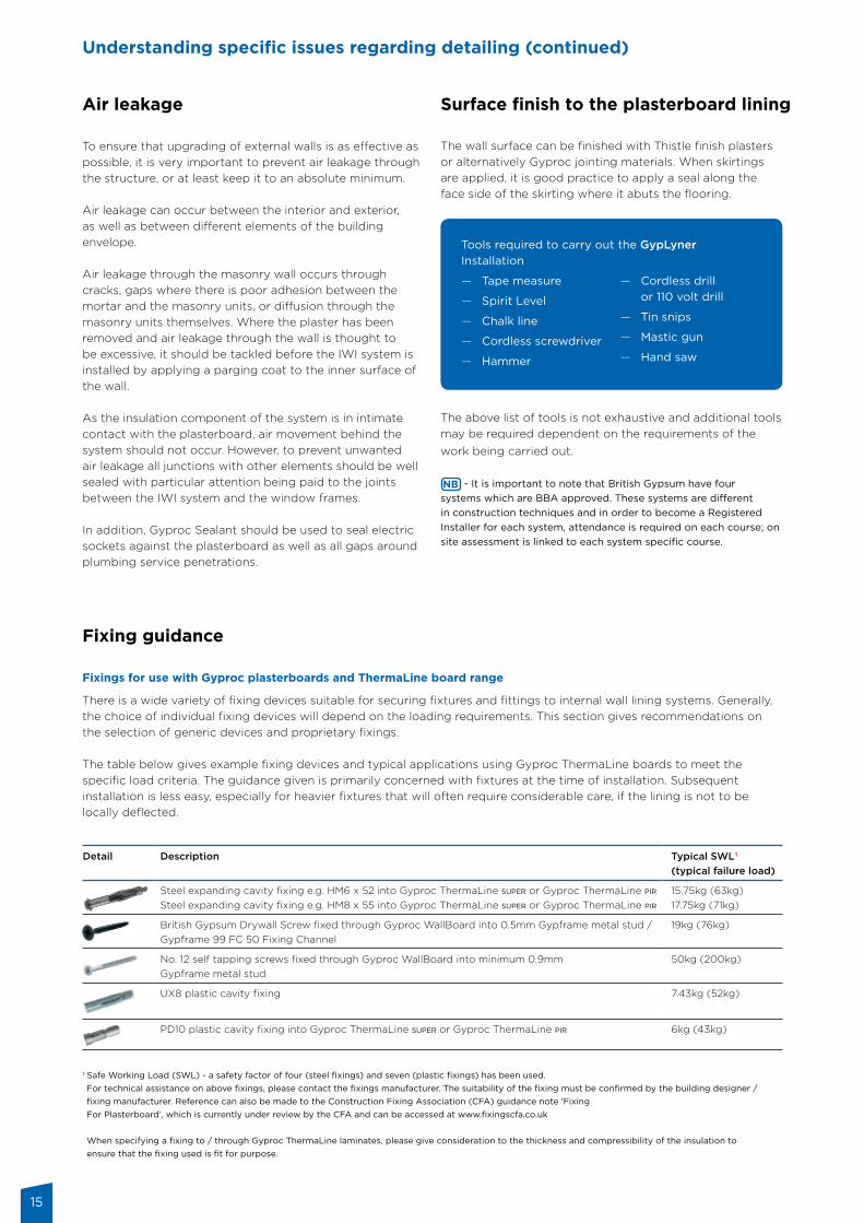
Fixing guidance Fixings for use with Gyproc plasterboards and ThermaLine board range
There is a wide variety of fixing devices suitable for securing fixtures and fittings to internal wall lining systems. Generally, the choice of individual fixing devices will depend on the loading requirements. This section gives recommendations on the selection of generic devices and proprietary fixings.
The table below gives example fixing devices and typical applications using Gyproc ThermaLine boards to meet the specific load criteria. The guidance given is primarily concerned with fixtures at the time of installation. Subsequent installation is less easy, especially for heavier fixtures that will often require considerable care, if the lining is not to be locally deflected.
The wall surface can be finished with Thistle finish plasters or alternatively Gyproc jointing materials. When skirtings are applied, it is good practice to apply a seal along the face side of the skirting where it abuts the flooring.
Tools required to carry out the GypLyner Installation
— Tape measure
— Spirit Level
— Chalk line
— Cordless screwdriver
— Hammer
— Cordless drill or 110 volt drill
— Tin snips
— Mastic gun
— Hand saw
The above list of tools is not exhaustive and additional tools may be required dependent on the requirements of the work being carried out.
- It is important to note that British Gypsum have four systems which are BBA approved. These systems are different in construction techniques and in order to become a Registered Installer for each system, attendance is required on each course; on site assessment is linked to each system specific course.
Surface finish to the plasterboard lining
Detail Description Typical SWL1 (typical failure load)
Steel expanding cavity fixing e.g. HM6 x 52 into Gyproc ThermaLine super or Gyproc ThermaLine pirSteel expanding cavity fixing e.g. HM8 x 55 into Gyproc ThermaLine super or Gyproc ThermaLine pir
15.75kg (63kg)17.75kg (71kg)
British Gypsum Drywall Screw fixed through Gyproc WallBoard into 0.5mm Gypframe metal stud / Gypframe 99 FC 50 Fixing Channel
19kg (76kg)
No. 12 self tapping screws fixed through Gyproc WallBoard into minimum 0.9mm Gypframe metal stud
50kg (200kg)
UX8 plastic cavity fixing 7.43kg (52kg)
PD10 plastic cavity fixing into Gyproc ThermaLine super or Gyproc ThermaLine pir 6kg (43kg)
1 Safe Working Load (SWL) - a safety factor of four (steel fixings) and seven (plastic fixings) has been used. For technical assistance on above fixings, please contact the fixings manufacturer. The suitability of the fixing must be confirmed by the building designer / fixing manufacturer. Reference can also be made to the Construction Fixing Association (CFA) guidance note ‘Fixing For Plasterboard’, which is currently under review by the CFA and can be accessed at www.fixingscfa.co.uk
When specifying a fixing to / through Gyproc ThermaLine laminates, please give consideration to the thickness and compressibility of the insulation to ensure that the fixing used is fit for purpose.

16
For further details on courses, locations and dates, please contact the Saint-Gobain Technical Academy on 0844 561 8810 or visit the British Gypsum website: british-gypsum.com
Saint-Gobain Technical Academy
The complete training service Our courses are designed to increase knowledge on the products and systems we offer, the regulations and market requirements that drive demand as well as providing practical guidance on installing our systems. Saint-Gobain Technical Academy training courses are run by fully qualified instructors at Kirkby Thore near Penrith, East Leake near Nottingham, Erith in Kent and Clevedon near Bristol.
Saint-Gobain Technical Academy training centre locations
Clevedon
Unit 1, The Courtyard Barnes Ground, Kenn, Clevedon, North Somerset BS21 6TB
East Leake
East Leake, Loughborough, Leicestershire, LE12 6HX
Erith
Church Manorway, Erith, Kent, DA8 1DE
Flitwick
Enterprise Way, Flitwick, Bedford, MK45 5BY
Kirkby Thore
Kirkby Thorem Nr. Penrith, Cumbria, CA10 1XU
Saint-Gobain Technical Academy satelite training centre location
South Lanarkshire College
College Way, East Kilbride, G75 0NE

17

18
Technical enquiriesBritish Gypsum Technical Advice CentreEast LeakeLoughboroughLeicestershire LE12 6HX
T: 0115 945 6123F: 0115 945 1616E: [email protected]
Training enquiries: 0844 561 8810
British Gypsum June 2017 BG-UNIG-02
british-gypsum.com
@britishgypsum
www.linkedin.com/company/british-gypsum
British GypsumHead Office, East Leake,
Loughborough, Leicestershire, LE12 6HX
Tel: 0115 945 1000