Embed Size (px)
Citation preview
Reference numberISO 3506-1:2009(E)
© ISO 2009
INTERNATIONAL STANDARD
ISO3506-1
Second edition2009-11-15
Mechanical properties of corrosion-resistant stainless steel fasteners — Part 1: Bolts, screws and studs
Caractéristiques mécaniques des éléments de fixation en acier inoxydable résistant à la corrosion —
Partie 1: Vis et goujons
--``,`,,`,,`,`,,`,`,,``,`,-`-`,,`,,`,`,,`---
ISO 3506-1:2009(E)
PDF disclaimer This PDF file may contain embedded typefaces. In accordance with Adobe's licensing policy, this file may be printed or viewed but shall not be edited unless the typefaces which are embedded are licensed to and installed on the computer performing the editing. In downloading this file, parties accept therein the responsibility of not infringing Adobe's licensing policy. The ISO Central Secretariat accepts no liability in this area.
Adobe is a trademark of Adobe Systems Incorporated.
Details of the software products used to create this PDF file can be found in the General Info relative to the file; the PDF-creation parameters were optimized for printing. Every care has been taken to ensure that the file is suitable for use by ISO member bodies. In the unlikely event that a problem relating to it is found, please inform the Central Secretariat at the address given below.
COPYRIGHT PROTECTED DOCUMENT © ISO 2009 All rights reserved. Unless otherwise specified, no part of this publication may be reproduced or utilized in any form or by any means, electronic or mechanical, including photocopying and microfilm, without permission in writing from either ISO at the address below or ISO's member body in the country of the requester.
ISO copyright office Case postale 56 • CH-1211 Geneva 20 Tel. + 41 22 749 01 11 Fax + 41 22 749 09 47 E-mail [email protected] Web www.iso.org
Published in Switzerland
ii © ISO 2009 – All rights reserved
--``,`,,`,,`,`,,`,`,,``,`,-`-`,,`,,`,`,,`---
ISO 3506-1:2009(E)
© ISO 2009 – All rights reserved iii
Contents Page
Foreword ............................................................................................................................................................iv Introduction.........................................................................................................................................................v 1 Scope ......................................................................................................................................................1 2 Normative references............................................................................................................................2 3 Symbols..................................................................................................................................................2 4 Designation, marking and finish..........................................................................................................3 4.1 Designation ............................................................................................................................................3 4.2 Marking...................................................................................................................................................4 4.3 Finish ......................................................................................................................................................6 5 Chemical composition ..........................................................................................................................6 6 Mechanical properties...........................................................................................................................7 7 Testing....................................................................................................................................................9 7.1 Test programme ....................................................................................................................................9 7.2 Test methods .......................................................................................................................................10 Annex A (normative) External thread – Calculation of stress area .............................................................14 Annex B (informative) Description of the groups and grades of stainless steels .....................................15 Annex C (informative) Stainless steel composition specifications .............................................................18 Annex D (informative) Stainless steels for cold heading and extruding.....................................................21 Annex E (informative) Austenitic stainless steels with particular resistance to chloride induced
stress corrosion ..................................................................................................................................23 Annex F (informative) Mechanical properties at elevated temperatures; application at low
temperatures........................................................................................................................................24 Annex G (informative) Time-temperature diagram of intergranular corrosion in austenitic
stainless steels, grade A2 (18/8 steels).............................................................................................25 Annex H (informative) Magnetic properties for austenitic stainless steels ................................................26 Bibliography......................................................................................................................................................27
--``,`,,`,,`,`,,`,`,,``,`,-`-`,,`,,`,`,,`---

ISO 3506-1:2009(E)
iv © ISO 2009 – All rights reserved
Foreword
ISO (the International Organization for Standardization) is a worldwide federation of national standards bodies (ISO member bodies). The work of preparing International Standards is normally carried out through ISO technical committees. Each member body interested in a subject for which a technical committee has been established has the right to be represented on that committee. International organizations, governmental and non-governmental, in liaison with ISO, also take part in the work. ISO collaborates closely with the International Electrotechnical Commission (IEC) on all matters of electrotechnical standardization.
International Standards are drafted in accordance with the rules given in the ISO/IEC Directives, Part 2.
The main task of technical committees is to prepare International Standards. Draft International Standards adopted by the technical committees are circulated to the member bodies for voting. Publication as an International Standard requires approval by at least 75 % of the member bodies casting a vote.
Attention is drawn to the possibility that some of the elements of this document may be the subject of patent rights. ISO shall not be held responsible for identifying any or all such patent rights.
ISO 3506-1 was prepared by Technical Committee ISO/TC 2, Fasteners, Subcommittee SC 1, Mechanical properties of fasteners.
This second edition cancels and replaces the first edition (ISO 3506-1:1997), which has been technically revised.
ISO 3506 consists of the following parts, under the general title Mechanical properties of corrosion-resistant stainless steel fasteners:
⎯ Part 1: Bolts, screws and studs
⎯ Part 2: Nuts
⎯ Part 3: Set screws and similar fasteners not under tensile stress
⎯ Part 4: Tapping screws
--``,`,,`,,`,`,,`,`,,``,`,-`-`,,`,,`,`,,`---
ISO 3506-1:2009(E)
© ISO 2009 – All rights reserved v
Introduction
In the preparation of this part of ISO 3506, special attention has been given to the fundamentally different property characteristics of the stainless steel fastener grades compared with those of carbon steel and low-alloy steel fasteners. Ferritic and austenitic stainless steels are strengthened only by cold working and consequently, the components do not have as homogeneous local material properties as hardened and tempered parts. These special features have been recognized in the elaboration of the property classes and the test procedures for mechanical properties. The latter differ from the carbon steel and low-alloy steel fastener test procedures with regard to the measurement of the stress at 0,2 % permanent strain (yield stress) and ductility (total elongation after fracture).
--``,`,,`,,`,`,,`,`,,``,`,-`-`,,`,,`,`,,`---

--``,`,,`,,`,`,,`,`,,``,`,-`-`,,`,,`,`,,`---
INTERNATIONAL STANDARD ISO 3506-1:2009(E)
© ISO 2009 – All rights reserved 1
Mechanical properties of corrosion-resistant stainless steel fasteners —
Part 1: Bolts, screws and studs
1 Scope
This part of ISO 3506 specifies the mechanical properties of bolts, screws and studs made of austenitic, martensitic and ferritic steel grades of corrosion-resistant stainless steels, when tested over an ambient temperature range of 10 °C to 35 °C. Properties vary at higher or lower temperatures.
This part of ISO 3506 applies to bolts, screws and studs
⎯ with nominal thread diameter d u 39 mm,
⎯ of triangular ISO metric threads with diameters and pitches in accordance with ISO 68-1, ISO 261 and ISO 262, and
⎯ of any shape.
It does not apply to screws with special properties, such as weldability.
NOTE The designation system of this part of ISO 3506 can be used for sizes outside the limits given in this clause (e.g. d > 39 mm), provided that all applicable mechanical and physical requirements of the property classes are met.
This part of ISO 3506 does not define corrosion or oxidation resistance in particular environments. However, some information on materials for particular environments is given in Annex E. Regarding definitions of corrosion and corrosion resistance, see ISO 8044.
The aim of this part of ISO 3506 is the classification of corrosion-resistant stainless steel fasteners1) into property classes. Some materials can be used at temperatures down to − 200 °C, while some can be used at temperatures up to + 800 °C in air. Information on the influence of temperature on mechanical properties is found in Annex F.
Corrosion and oxidation performances and mechanical properties for use at elevated or sub-zero temperatures can be agreed on between the user and the manufacturer in each particular case. Annex G shows how the risk of intergranular corrosion at elevated temperatures depends on the carbon content.
All austenitic stainless steel fasteners are normally non-magnetic in the annealed condition; after cold working, some magnetic properties can be evident (see Annex H).
1) The term “fasteners” is used when bolts, screws and studs are considered all together.
--``,`,,`,,`,`,,`,`,,``,`,-`-`,,`,,`,`,,`---
ISO 3506-1:2009(E)
2 © ISO 2009 – All rights reserved
2 Normative references
The following referenced documents are indispensable for the application of this document. For dated references, only the edition cited applies. For undated references, the latest edition of the referenced document (including any amendments) applies.
ISO 68-1, ISO general purpose screw threads — Basic profile — Part 1: Metric screw threads
ISO 261, ISO general purpose metric screw threads — General plan
ISO 262, ISO general purpose metric screw threads — Selected sizes for screws, bolts and nuts
ISO 898-1, Mechanical properties of fasteners made of carbon steel and alloy steel — Part 1: Bolts, screws and studs with specified property classes — Coarse thread and fine pitch thread
ISO 3651-1, Determination of resistance to intergranular corrosion of stainless steels — Part 1: Austenitic and ferritic-austenitic (duplex) stainless steels — Corrosion test in nitric acid medium by measurement of loss in mass (Huey test)
ISO 3651-2, Determination of resistance to intergranular corrosion of stainless steels — Part 2: Ferritic, austenitic and ferritic-austenitic (duplex) stainless steels — Corrosion test in media containing sulfuric acid
ISO 6506-1, Metallic materials — Brinell hardness test — Part 1: Test method
ISO 6507-1, Metallic materials — Vickers hardness test — Part 1: Test method
ISO 6508-1, Metallic materials — Rockwell hardness test — Part 1: Test method (scales A, B, C, D, E, F, G, H, K, N, T)
ISO 6892-1, Metallic materials — Tensile testing — Part 1: Method of test at room temperature
ISO 16048, Passivation of corrosion-resistant stainless-steel fasteners
ISO 16426, Fasteners — Quality assurance system
3 Symbols
A elongation after fracture
As,nom nominal stress area
d nominal thread diameter
d1 basic minor diameter of external thread
d2 basic pitch diameter of external thread
d3 minor diameter of external thread (for stress calculation)
H height of the fundamental triangle of the thread
L1 total length of fastener
L2 total length of fastener after fracture
L3 distance between the underside of the head and the threaded adapter
l nominal length of the fastener
ls plain shank length
--``,`,,`,,`,`,,`,`,,``,`,-`-`,,`,,`,`,,`---
ISO 3506-1:2009(E)
© ISO 2009 – All rights reserved 3
MB breaking torque
P pitch of the thread
ReL lower yield stress
Rm tensile strength
Rp0,2 stress at 0,2 % permanent strain
α wedge angle
µr permeability value in a magnetic field
4 Designation, marking and finish
4.1 Designation
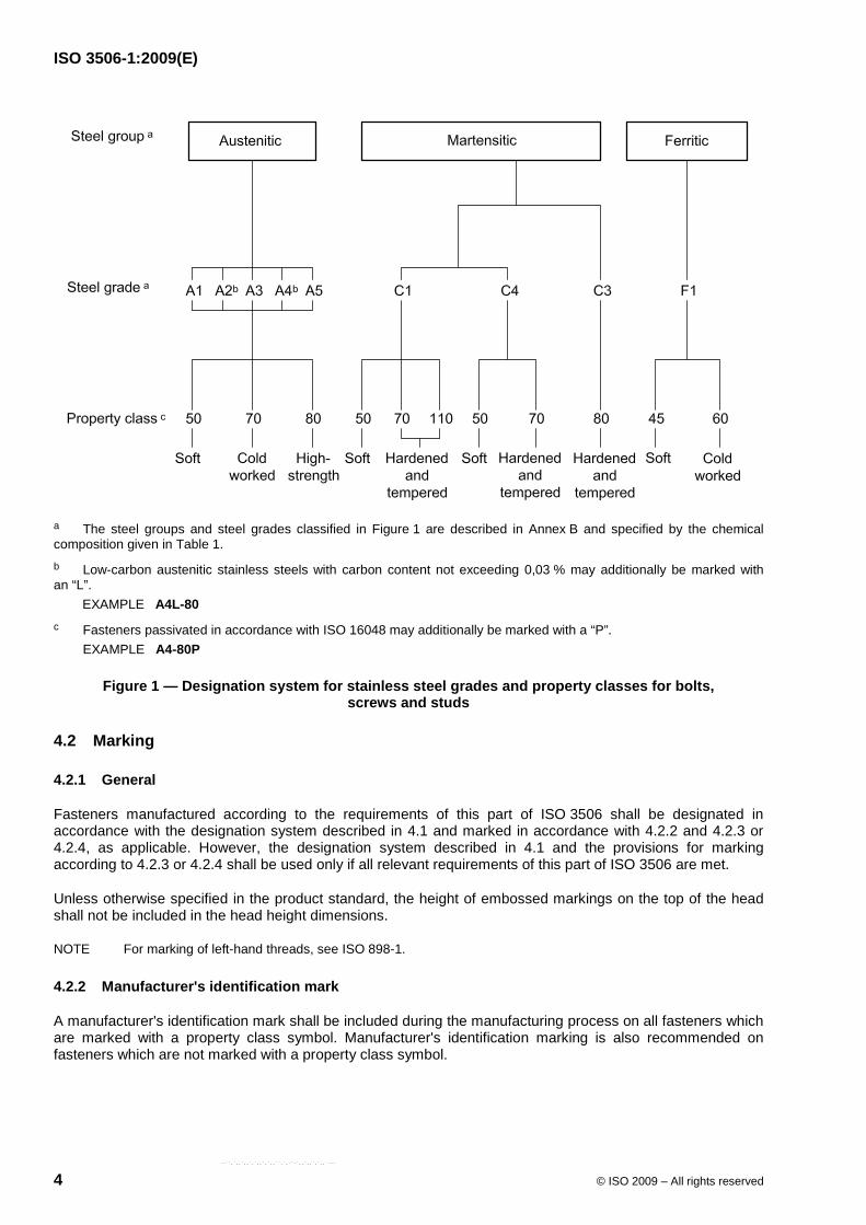
The designation system for stainless steel grades and property classes for bolts, screws and studs is given in Figure 1. The designation of the material consists of two blocks, which are separated by a hyphen. The first block designates the steel grade and the second block, the property class.
The designation of the steel grade (first block) consists of one of the letters
⎯ A for austenitic steel,
⎯ C for martensitic steel, or
⎯ F for ferritic steel
which indicates the group of steel and a digit, which indicates a range of chemical compositions within this steel group (see Table 1).
The designation of the property class (second block) consists of two or three digits representing 1/10 of the tensile strength of the fastener, according to Table 2 or Table 3.
EXAMPLE 1 A2-70 indicates: austenitic steel, cold worked, minimum 700 MPa tensile strength.
EXAMPLE 2 C4-70 indicates: martensitic steel, hardened and tempered, minimum 700 MPa tensile strength.
--``,`,,`,,`,`,,`,`,,``,`,-`-`,,`,,`,`,,`---
ISO 3506-1:2009(E)
4 © ISO 2009 – All rights reserved
a The steel groups and steel grades classified in Figure 1 are described in Annex B and specified by the chemical composition given in Table 1. b Low-carbon austenitic stainless steels with carbon content not exceeding 0,03 % may additionally be marked with an “L”.
EXAMPLE A4L-80 c Fasteners passivated in accordance with ISO 16048 may additionally be marked with a “P”.
EXAMPLE A4-80P
Figure 1 — Designation system for stainless steel grades and property classes for bolts, screws and studs
4.2 Marking
4.2.1 General
Fasteners manufactured according to the requirements of this part of ISO 3506 shall be designated in accordance with the designation system described in 4.1 and marked in accordance with 4.2.2 and 4.2.3 or 4.2.4, as applicable. However, the designation system described in 4.1 and the provisions for marking according to 4.2.3 or 4.2.4 shall be used only if all relevant requirements of this part of ISO 3506 are met.
Unless otherwise specified in the product standard, the height of embossed markings on the top of the head shall not be included in the head height dimensions.
NOTE For marking of left-hand threads, see ISO 898-1.
4.2.2 Manufacturer's identification mark
A manufacturer's identification mark shall be included during the manufacturing process on all fasteners which are marked with a property class symbol. Manufacturer's identification marking is also recommended on fasteners which are not marked with a property class symbol.
--``,`,,`,,`,`,,`,`,,``,`,-`-`,,`,,`,`,,`---
ISO 3506-1:2009(E)
© ISO 2009 – All rights reserved 5
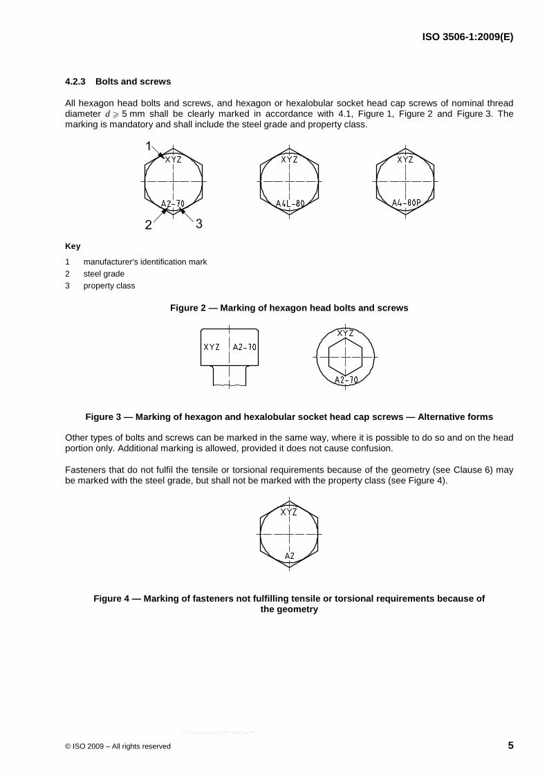
4.2.3 Bolts and screws
All hexagon head bolts and screws, and hexagon or hexalobular socket head cap screws of nominal thread diameter d W 5 mm shall be clearly marked in accordance with 4.1, Figure 1, Figure 2 and Figure 3. The marking is mandatory and shall include the steel grade and property class.
Key
1 manufacturer's identification mark 2 steel grade 3 property class
Figure 2 — Marking of hexagon head bolts and screws
Figure 3 — Marking of hexagon and hexalobular socket head cap screws — Alternative forms
Other types of bolts and screws can be marked in the same way, where it is possible to do so and on the head portion only. Additional marking is allowed, provided it does not cause confusion.
Fasteners that do not fulfil the tensile or torsional requirements because of the geometry (see Clause 6) may be marked with the steel grade, but shall not be marked with the property class (see Figure 4).
Figure 4 — Marking of fasteners not fulfilling tensile or torsional requirements because of the geometry
--``,`,,`,,`,`,,`,`,,``,`,-`-`,,`,,`,`,,`---
ISO 3506-1:2009(E)
6 © ISO 2009 – All rights reserved
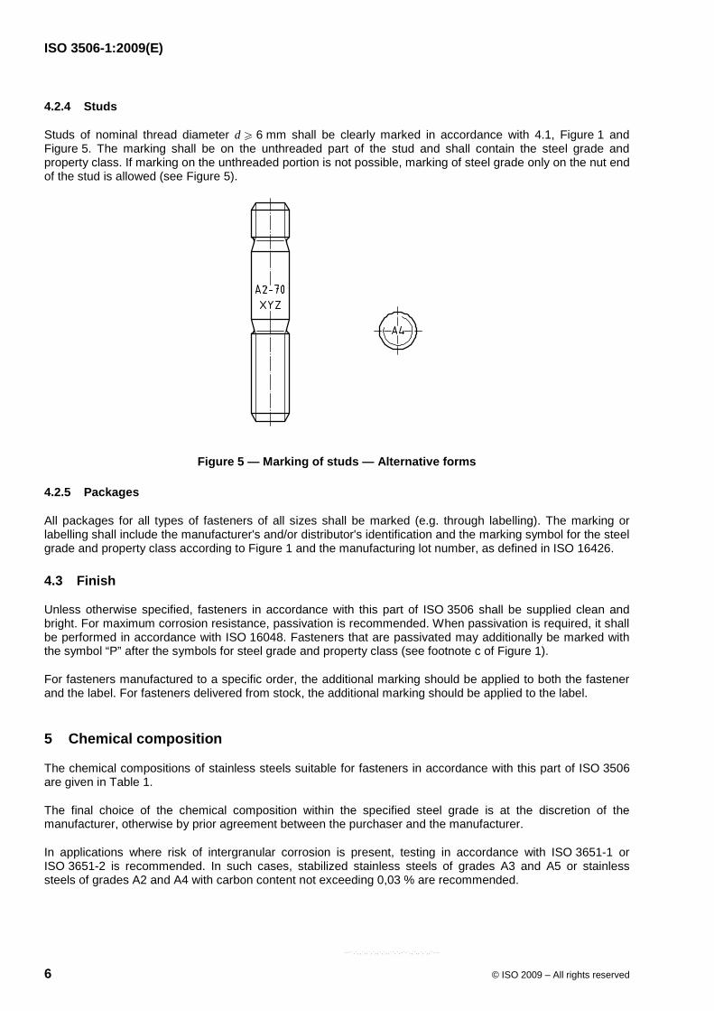
4.2.4 Studs
Studs of nominal thread diameter d W 6 mm shall be clearly marked in accordance with 4.1, Figure 1 and Figure 5. The marking shall be on the unthreaded part of the stud and shall contain the steel grade and property class. If marking on the unthreaded portion is not possible, marking of steel grade only on the nut end of the stud is allowed (see Figure 5).
Figure 5 — Marking of studs — Alternative forms
4.2.5 Packages
All packages for all types of fasteners of all sizes shall be marked (e.g. through labelling). The marking or labelling shall include the manufacturer's and/or distributor's identification and the marking symbol for the steel grade and property class according to Figure 1 and the manufacturing lot number, as defined in ISO 16426.
4.3 Finish
Unless otherwise specified, fasteners in accordance with this part of ISO 3506 shall be supplied clean and bright. For maximum corrosion resistance, passivation is recommended. When passivation is required, it shall be performed in accordance with ISO 16048. Fasteners that are passivated may additionally be marked with the symbol “P” after the symbols for steel grade and property class (see footnote c of Figure 1).
For fasteners manufactured to a specific order, the additional marking should be applied to both the fastener and the label. For fasteners delivered from stock, the additional marking should be applied to the label.
5 Chemical composition
The chemical compositions of stainless steels suitable for fasteners in accordance with this part of ISO 3506 are given in Table 1.
The final choice of the chemical composition within the specified steel grade is at the discretion of the manufacturer, otherwise by prior agreement between the purchaser and the manufacturer.
In applications where risk of intergranular corrosion is present, testing in accordance with ISO 3651-1 or ISO 3651-2 is recommended. In such cases, stabilized stainless steels of grades A3 and A5 or stainless steels of grades A2 and A4 with carbon content not exceeding 0,03 % are recommended.
--``,`,,`,,`,`,,`,`,,``,`,-`-`,,`,,`,`,,`---
ISO 3506-1:2009(E)
© ISO 2009 – All rights reserved 7
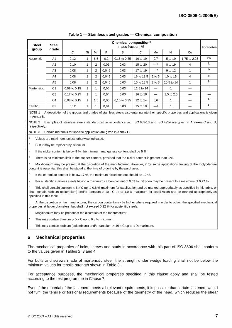
Table 1 — Stainless steel grades — Chemical composition
Chemical compositiona mass fraction, % Steel
group Steel grade
C Si Mn P S Cr Mo Ni Cu Footnotes
Austenitic A1 0,12 1 6,5 0,2 0,15 to 0,35 16 to 19 0,7 5 to 10 1,75 to 2,25 bcd
A2 0,10 1 2 0,05 0,03 15 to 20 —e 8 to 19 4 fg
A3 0,08 1 2 0,045 0,03 17 to 19 —e 9 to 12 1 h
A4 0,08 1 2 0,045 0,03 16 to 18,5 2 to 3 10 to 15 4 gi
A5 0,08 1 2 0,045 0,03 16 to 18,5 2 to 3 10,5 to 14 1 hi
Martensitic C1 0,09 to 0,15 1 1 0,05 0,03 11,5 to 14 — 1 — i
C3 0,17 to 0,25 1 1 0,04 0,03 16 to 18 — 1,5 to 2,5 — —
C4 0,08 to 0,15 1 1,5 0,06 0,15 to 0,35 12 to 14 0,6 1 — bi
Ferritic F1 0,12 1 1 0,04 0,03 15 to 18 —j 1 — kl
NOTE 1 A description of the groups and grades of stainless steels also entering into their specific properties and applications is given in Annex B.
NOTE 2 Examples of stainless steels standardized in accordance with ISO 683-13 and ISO 4954 are given in Annexes C and D,respectively.
NOTE 3 Certain materials for specific application are given in Annex E. a Values are maximum, unless otherwise indicated. b Sulfur may be replaced by selenium.
c If the nickel content is below 8 %, the minimum manganese content shall be 5 %.
d There is no minimum limit to the copper content, provided that the nickel content is greater than 8 %.
e Molybdenum may be present at the discretion of the manufacturer. However, if for some applications limiting of the molybdenum content is essential, this shall be stated at the time of ordering by the purchaser.
f If the chromium content is below 17 %, the minimum nickel content should be 12 %.
g For austenitic stainless steels having a maximum carbon content of 0,03 %, nitrogen may be present to a maximum of 0,22 %.
h This shall contain titanium W 5 × C up to 0,8 % maximum for stabilization and be marked appropriately as specified in this table, or shall contain niobium (columbium) and/or tantalum W 10 × C up to 1,0 % maximum for stabilization and be marked appropriately as specified in this table.
i At the discretion of the manufacturer, the carbon content may be higher where required in order to obtain the specified mechanical properties at larger diameters, but shall not exceed 0,12 % for austenitic steels.
j Molybdenum may be present at the discretion of the manufacturer.
k This may contain titanium W 5 × C up to 0,8 % maximum.
l This may contain niobium (columbium) and/or tantalum W 10 × C up to 1 % maximum.
6 Mechanical properties
The mechanical properties of bolts, screws and studs in accordance with this part of ISO 3506 shall conform to the values given in Tables 2, 3 and 4.
For bolts and screws made of martensitic steel, the strength under wedge loading shall not be below the minimum values for tensile strength shown in Table 3.
For acceptance purposes, the mechanical properties specified in this clause apply and shall be tested according to the test programme in Clause 7.
Even if the material of the fasteners meets all relevant requirements, it is possible that certain fasteners would not fulfil the tensile or torsional requirements because of the geometry of the head, which reduces the shear
--``,`,,`,,`,`,,`,`,,``,`,-`-`,,`,,`,`,,`---
ISO 3506-1:2009(E)
8 © ISO 2009 – All rights reserved
area in the head compared to the stress area in the thread such as countersunk, raised countersunk and cheese heads.
NOTE Although a great number of property classes are specified in this part of ISO 3506, this does not mean that all classes are appropriate for all fasteners. Further guidance for application of the specific property classes is given in the relevant product standards.
For non-standard fasteners, the choice already made for similar standard fasteners should be followed as closely as possible.
Table 2 — Mechanical properties for bolts, screws and studs — Austenitic steel grades
Steel group Steel grade Property class
Tensile strength
Rm a
min. MPa
Stress at 0,2 % permanent strain
Rp0,2a
min. MPa
Elongation after fracture
Ab min. mm
Austenitic A1, A2, 50 500 210 0,6d
A3, A4, 70 700 450 0,4d
A5 80 800 600 0,3d
a The tensile stress is calculated on the stress area (see Annex A).
b This is determined according to 7.2.4, on the actual screw length and not on a prepared test piece.
Table 3 — Mechanical properties for bolts, screws and studs — Martensitic and ferritic steel grades
Tensile strength
Rma
min.
Stress at 0,2 % permanent strain
Rp0,2a
min.
Elongation after
fracture Ab
min.
Hardness Steel group Steel
grade Property
class
MPa MPa mm HB HRC HV
Martensitic 50 500 250 0,2d 147 to 209 — 155 to 220
70 700 410 0,2d 209 to 314 20 to 34 220 to 330
C1
110c 1 100 820 0,2d — 36 to 45 350 to 440
C3 80 800 640 0,2d 228 to 323 21 to 35 240 to 340
50 500 250 0,2d 147 to 209 — 155 to 220
C4
70 700 410 0,2d 209 to 314 20 to 34 220 to 330
Ferritic F1d 45 450 250 0,2d 128 to 209 — 135 to 220
60 600 410 0,2d 171 to 271 — 180 to 285
a The tensile stress is calculated on the stress area (see Annex A).
b This is determined according to 7.2.4, on the actual screw length and not on a prepared test piece.
c Hardened and tempered at a minimum tempering temperature of 275 °C.
d Nominal thread diameter d u 24 mm.
--``,`,,`,,`,`,,`,`,,``,`,-`-`,,`,,`,`,,`---
ISO 3506-1:2009(E)
© ISO 2009 – All rights reserved 9
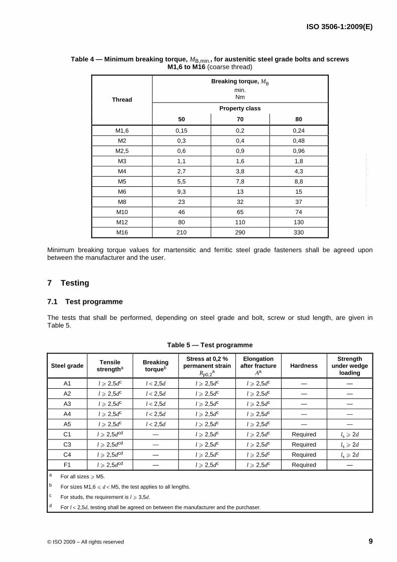
Table 4 — Minimum breaking torque, MB,min., for austenitic steel grade bolts and screws M1,6 to M16 (coarse thread)
Breaking torque, MB
min. Nm
Property class Thread
50 70 80
M1,6 0,15 0,2 0,24
M2 0,3 0,4 0,48
M2,5 0,6 0,9 0,96
M3 1,1 1,6 1,8
M4 2,7 3,8 4,3
M5 5,5 7,8 8,8
M6 9,3 13 15
M8 23 32 37
M10 46 65 74
M12 80 110 130
M16 210 290 330
Minimum breaking torque values for martensitic and ferritic steel grade fasteners shall be agreed upon between the manufacturer and the user.
7 Testing
7.1 Test programme
The tests that shall be performed, depending on steel grade and bolt, screw or stud length, are given in Table 5.
Table 5 — Test programme
Steel grade Tensile strengtha
Breaking torqueb
Stress at 0,2 % permanent strain
Rp0,2a
Elongation after fracture
Aa Hardness
Strength under wedge
loading
A1 l W 2,5dc l < 2,5d l W 2,5dc l W 2,5dc — —
A2 l W 2,5dc l < 2,5d l W 2,5dc l W 2,5dc — —
A3 l W 2,5dc l < 2,5d l W 2,5dc l W 2,5dc — —
A4 l W 2,5dc l < 2,5d l W 2,5dc l W 2,5dc — —
A5 l W 2,5dc l < 2,5d l W 2,5dc l W 2,5dc — —
C1 l W 2,5dcd — l W 2,5dc l W 2,5dc Required ls W 2d
C3 l W 2,5dcd — l W 2,5dc l W 2,5dc Required ls W 2d
C4 l W 2,5dcd — l W 2,5dc l W 2,5dc Required ls W 2d
F1 l W 2,5dcd — l W 2,5dc l W 2,5dc Required — a For all sizes W M5. b For sizes M1,6 u d < M5, the test applies to all lengths. c For studs, the requirement is l W 3,5d. d For l < 2,5d, testing shall be agreed on between the manufacturer and the purchaser.
--``,`,,`,,`,`,,`,`,,``,`,-`-`,,`,,`,`,,`---
ISO 3506-1:2009(E)
10 © ISO 2009 – All rights reserved
7.2 Test methods
7.2.1 General
All length measurements shall be made with an accuracy of ± 0,05 mm or better.
All tensile tests except under wedge loading (7.2.6) shall be performed with testing machines equipped with self-aligning grips in order to prevent any non-axial loading (see Figure 6). The lower adapter shall be hardened and threaded for tests according to 7.2.2, 7.2.3 and 7.2.4. The hardness of the lower adapter shall be 45 HRC minimum. Internal thread tolerance class shall be 5H6G.
7.2.2 Tensile strength, Rm
The tensile strength, Rm, shall be determined on fasteners with l W 2,5d in accordance with ISO 6892-1 and ISO 898-1.
A free threaded length at least equal to the nominal diameter shall be subject to the tensile load.
In order to meet the requirements of this test, the fracture shall occur in the free threaded length or in the unthreaded shank. The fracture shall not occur in the head.
For fasteners with unthreaded shanks, the fracture shall not occur in the transition section between the head and the shank.
For screws threaded to the head, the fracture which causes failure may extend or spread into the transition section between the head and the thread or into the head before separation, provided that it originates in the free threaded length.
The obtained value for Rm shall meet the values given in Tables 2 and 3.
7.2.3 Stress at 0,2 % permanent strain, Rp0,2
The stress at 0,2 % permanent strain, Rp0,2, shall be determined only on complete bolts and screws in the finished condition. This test is applicable only to fasteners with l W 2,5d.
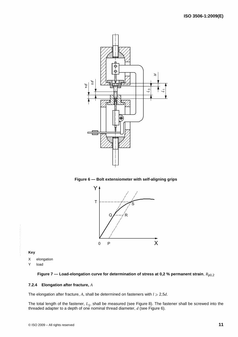
The test shall be carried out by measuring the extension of the bolt or screw when subjected to axial tensile loading (see Figure 6).
The component under test shall be screwed into a hardened threaded adapter to a depth of one thread diameter, d (see Figure 6).
A curve of load against elongation shall be plotted as shown in Figure 7.
The clamping length from which Rp0,2 is calculated is taken as the distance between the underside of the head and the threaded adapter, L3 (see Figure 6 and also footnote b of Tables 2 and 3). Of this value, 0,2 % is applied to scale to the horizontal (strain) axis of the load-elongation curve, OP, and the same value is plotted horizontally from the straight-line portion of the curve as QR. A line is drawn through P and R and the intersection, S, of this line with the load-elongation curve, corresponds to a load at point T on the vertical axis. This load, when divided by the thread stress area, gives the stress at 0,2 % permanent strain, Rp0,2.
The value of elongation is determined between the bearing face of the bolt head and the end of the adapter.
--``,`,,`,,`,`,,`,`,,``,`,-`-`,,`,,`,`,,`---
ISO 3506-1:2009(E)
© ISO 2009 – All rights reserved 11
Figure 6 — Bolt extensiometer with self-aligning grips
Key
X elongation Y load
Figure 7 — Load-elongation curve for determination of stress at 0,2 % permanent strain, Rp0,2
7.2.4 Elongation after fracture, A
The elongation after fracture, A, shall be determined on fasteners with l W 2,5d.
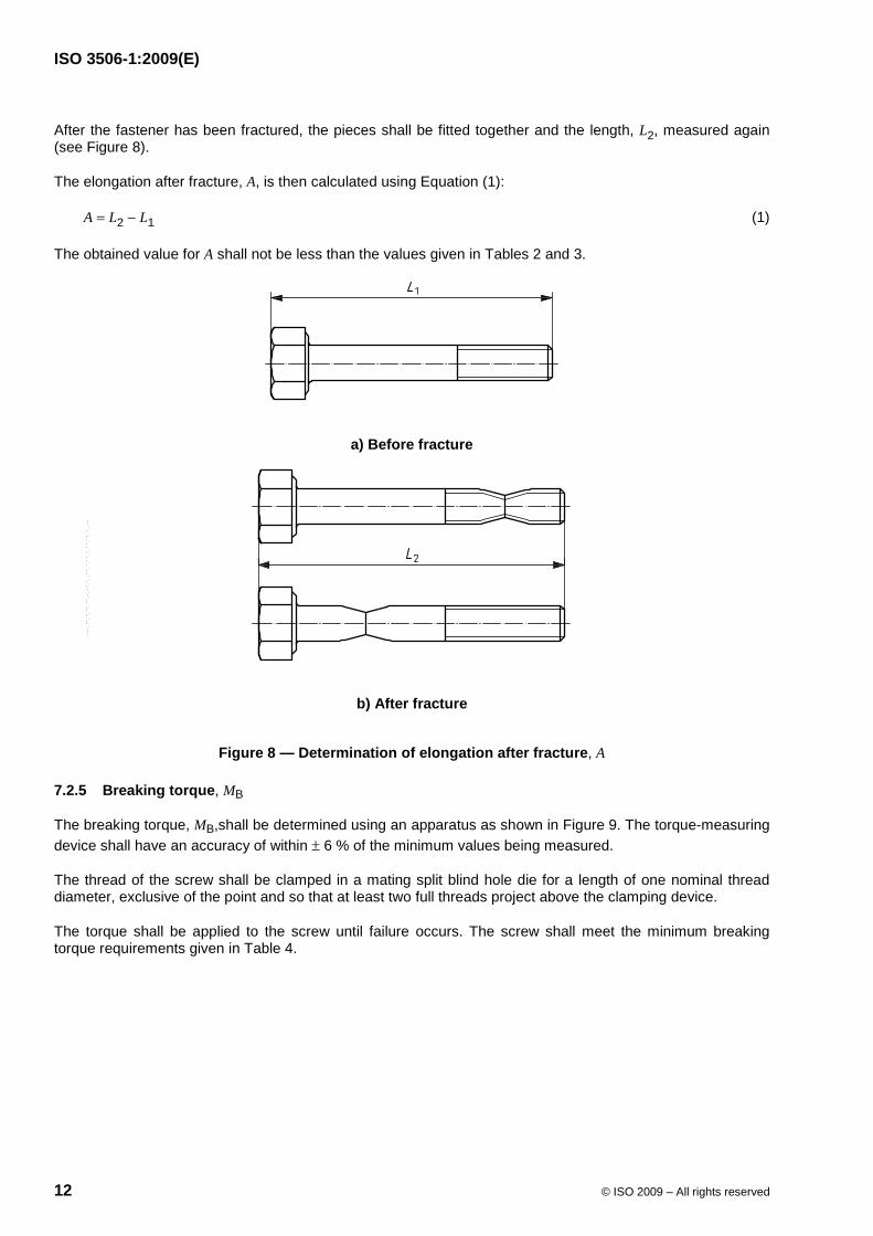
The total length of the fastener, L1, shall be measured (see Figure 8). The fastener shall be screwed into the threaded adapter to a depth of one nominal thread diameter, d (see Figure 6).
--``,`,,`,,`,`,,`,`,,``,`,-`-`,,`,,`,`,,`---
ISO 3506-1:2009(E)
12 © ISO 2009 – All rights reserved
After the fastener has been fractured, the pieces shall be fitted together and the length, L2, measured again (see Figure 8).
The elongation after fracture, A, is then calculated using Equation (1):
A = L2 − L1 (1)
The obtained value for A shall not be less than the values given in Tables 2 and 3.
a) Before fracture
b) After fracture
Figure 8 — Determination of elongation after fracture, A
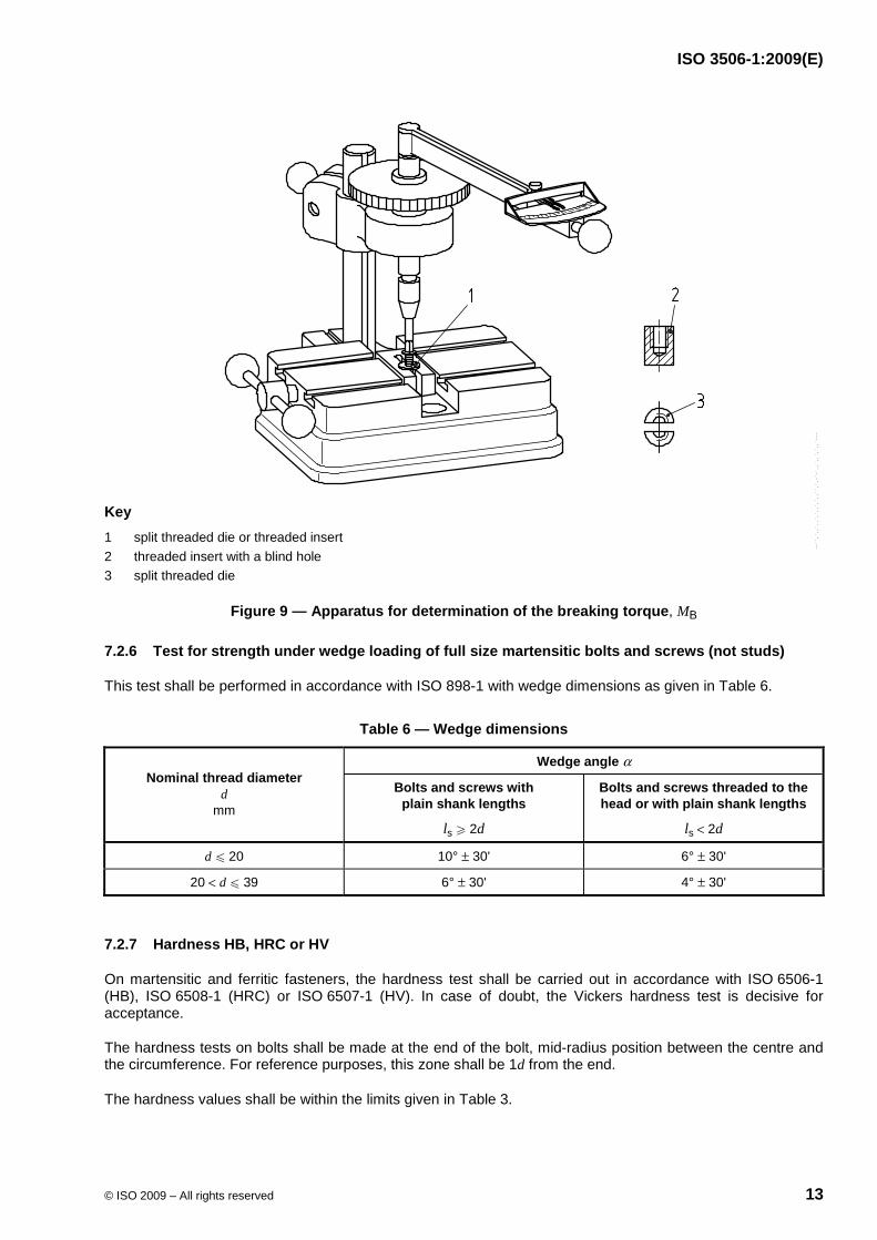
7.2.5 Breaking torque, MB
The breaking torque, MB,shall be determined using an apparatus as shown in Figure 9. The torque-measuring device shall have an accuracy of within ± 6 % of the minimum values being measured.
The thread of the screw shall be clamped in a mating split blind hole die for a length of one nominal thread diameter, exclusive of the point and so that at least two full threads project above the clamping device.
The torque shall be applied to the screw until failure occurs. The screw shall meet the minimum breaking torque requirements given in Table 4.
--``,`,,`,,`,`,,`,`,,``,`,-`-`,,`,,`,`,,`---
ISO 3506-1:2009(E)
© ISO 2009 – All rights reserved 13
Key 1 split threaded die or threaded insert 2 threaded insert with a blind hole 3 split threaded die
Figure 9 — Apparatus for determination of the breaking torque, MB
7.2.6 Test for strength under wedge loading of full size martensitic bolts and screws (not studs)
This test shall be performed in accordance with ISO 898-1 with wedge dimensions as given in Table 6.
Table 6 — Wedge dimensions
Wedge angle α Nominal thread diameter
d mm
Bolts and screws with plain shank lengths
ls W 2d
Bolts and screws threaded to the head or with plain shank lengths
ls < 2d
d u 20 10° ± 30' 6° ± 30'
20 < d u 39 6° ± 30' 4° ± 30'
7.2.7 Hardness HB, HRC or HV
On martensitic and ferritic fasteners, the hardness test shall be carried out in accordance with ISO 6506-1 (HB), ISO 6508-1 (HRC) or ISO 6507-1 (HV). In case of doubt, the Vickers hardness test is decisive for acceptance.
The hardness tests on bolts shall be made at the end of the bolt, mid-radius position between the centre and the circumference. For reference purposes, this zone shall be 1d from the end.
The hardness values shall be within the limits given in Table 3.
--``,`,,`,,`,`,,`,`,,``,`,-`-`,,`,,`,`,,`---
ISO 3506-1:2009(E)
14 © ISO 2009 – All rights reserved
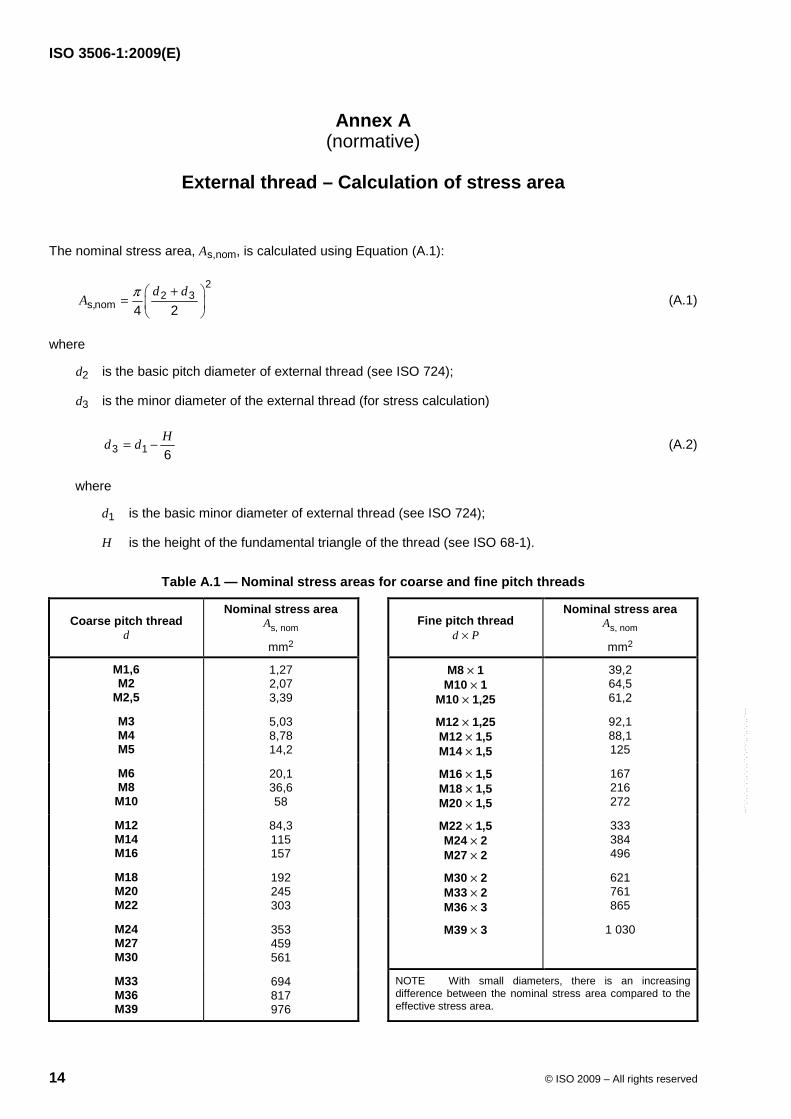
Annex A (normative)
External thread – Calculation of stress area
The nominal stress area, As,nom, is calculated using Equation (A.1):
22 3
s,nom 4 2d d
A π +⎛ ⎞= ⎜ ⎟⎝ ⎠
(A.1)
where
d2 is the basic pitch diameter of external thread (see ISO 724);
d3 is the minor diameter of the external thread (for stress calculation)
3 1 6Hd d= − (A.2)
where
d1 is the basic minor diameter of external thread (see ISO 724);
H is the height of the fundamental triangle of the thread (see ISO 68-1).
Table A.1 — Nominal stress areas for coarse and fine pitch threads
Coarse pitch thread d
Nominal stress area As, nom
mm2
Fine pitch thread
d × P
Nominal stress area As, nom
mm2
M1,6 M2
M2,5
1,27 2,07 3,39
M8 × 1 M10 × 1
M10 × 1,25
39,2 64,5 61,2
M3 M4 M5
5,03 8,78 14,2
M12 × 1,25 M12 × 1,5 M14 × 1,5
92,1 88,1 125
M6 M8
M10
20,1 36,6 58
M16 × 1,5 M18 × 1,5 M20 × 1,5
167 216 272
M12 M14 M16
84,3 115 157
M22 × 1,5 M24 × 2 M27 × 2
333 384 496
M18 M20 M22
192 245 303
M30 × 2 M33 × 2 M36 × 3
621 761 865
M24 M27 M30
353 459 561
M39 × 3 1 030
M33 M36 M39
694 817 976
NOTE With small diameters, there is an increasing difference between the nominal stress area compared to the effective stress area.
--``,`,,`,,`,`,,`,`,,``,`,-`-`,,`,,`,`,,`---
ISO 3506-1:2009(E)
© ISO 2009 – All rights reserved 15
Annex B (informative)
Description of the groups and grades of stainless steels
B.1 General
In ISO 3506 (all parts), reference is made to steel grades A1 to A5, C1 to C4 and F1, covering steels of the following groups:
⎯ Austenitic steel A1 to A5;
⎯ Martensitic steel C1 to C4;
⎯ Ferritic steel F1.
The characteristics of the above-mentioned steel groups and steel grades are described in this annex.
This annex also gives some information on the non-standardized steel group FA. Steels of this group have a ferritic-austenitic structure.
B.2 Steel group A (austenitic structure)
B.2.1 General
Five main grades of austenitic steels, A1 to A5, are included in ISO 3506 (all parts). They cannot be hardened and are usually non-magnetic. In order to reduce the susceptibility to work hardening, copper may be added to the steel grades A1 to A5, as specified in Table 1.
For non-stabilized steel grades A2 and A4, the following applies.
⎯ As chromic oxide makes steel resistant to corrosion, low carbon content is of great importance to non-stabilized steels. Due to the high affinity of chrome to carbon, chrome carbide is obtained instead of chromic oxide, which is more likely at elevated temperature (see Annex G).
For stabilized steel grades A3 and A5, the following applies.
⎯ The elements Ti, Nb or Ta affect the carbon, and chromic oxide is produced to its full extent.
For offshore or similar applications, steels with Cr and Ni content of about 20 % and Mo of 4,5 % to 6,5 % are required.
When risk of corrosion is high, experts should be consulted.
B.2.2 Steel grade A1
Steels of grade A1 are specially designed for machining. Due to high sulfur content, the steels within this grade have lower resistance to corrosion than corresponding steels with normal sulfur content.
--``,`,,`,,`,`,,`,`,,``,`,-`-`,,`,,`,`,,`---
ISO 3506-1:2009(E)
16 © ISO 2009 – All rights reserved
B.2.3 Steel grade A2
Steels of grade A2 are the most frequently used stainless steels. They are used for kitchen equipment and apparatus for the chemical industry. Steels within this grade are not suitable for use in non-oxidizing acid and agents with chloride content, i.e. in swimming pools and sea water.
B.2.4 Steel grade A3
Steels of grade A3 are stabilized “stainless steels” with properties of steels of grade A2.
B.2.5 Steel grade A4
Steels of grade A4 are “acid proof steels”, which are molybdenum alloyed and give a considerably better resistance to corrosion. A4 is used to a great extent by the cellulose industry, as this steel grade is developed for boiling sulfuric acid (hence the name “acid proof”) and is, to a certain extent, also suitable in an environment with chloride content. A4 is also frequently used by the food industry and by the shipbuilding industry.
B.2.6 Steel grade A5
Steels of grade A5 are stabilized “acid proof steels” with properties of steels of grade A4.
B.3 Steel group F (ferritic structure)
B.3.1 General
One ferritic steel grade, F1, is included in ISO 3506 (all parts). The steels within F1 cannot normally be hardened and should not be hardened even if possible in certain cases. The F1 steels are magnetic.
B.3.2 Steel grade F1
Steels of grade F1 are normally used for simpler equipment with the exception of the superferrites, which have extremely low C and N contents. The steels within grade F1 can, if need be, replace steels of grades A2 and A3 and be used in an environment with a higher chloride content.
B.4 Steel group C (martensitic structure)
B.4.1 General
Three types of martensitic steel grades, C1, C3 and C4, are included in this part of ISO 3506. They can be hardened to an excellent strength and are magnetic.
B.4.2 Steel grade C1
Steels of grade C1 have limited resistance to corrosion. They are used in turbines, pumps and knives.
B.4.3 Steel grade C3
Steels of grade C3 have limited resistance to corrosion, though better resistance than C1. They are used in pumps and valves.
--``,`,,`,,`,`,,`,`,,``,`,-`-`,,`,,`,`,,`---
ISO 3506-1:2009(E)
© ISO 2009 – All rights reserved 17
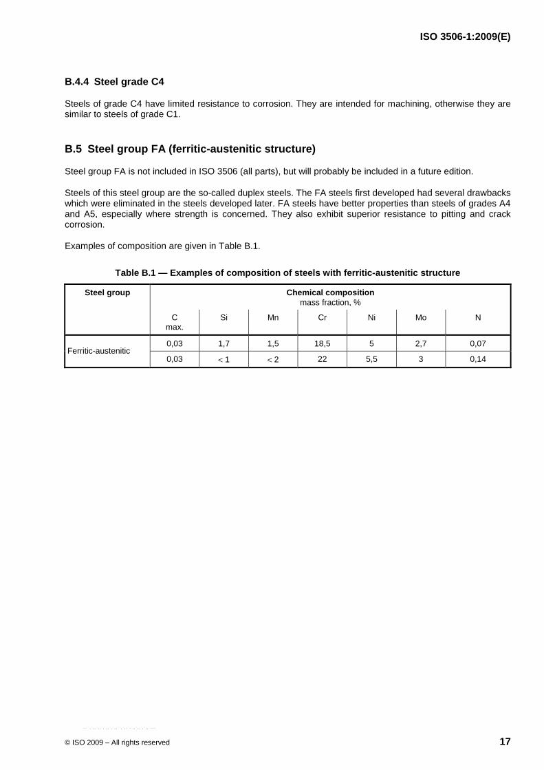
B.4.4 Steel grade C4
Steels of grade C4 have limited resistance to corrosion. They are intended for machining, otherwise they are similar to steels of grade C1.
B.5 Steel group FA (ferritic-austenitic structure)
Steel group FA is not included in ISO 3506 (all parts), but will probably be included in a future edition.
Steels of this steel group are the so-called duplex steels. The FA steels first developed had several drawbacks which were eliminated in the steels developed later. FA steels have better properties than steels of grades A4 and A5, especially where strength is concerned. They also exhibit superior resistance to pitting and crack corrosion.
Examples of composition are given in Table B.1.
Table B.1 — Examples of composition of steels with ferritic-austenitic structure
Steel group Chemical composition mass fraction, %
C max.
Si Mn Cr Ni Mo N
0,03 1,7 1,5 18,5 5 2,7 0,07 Ferritic-austenitic
0,03 < 1 < 2 22 5,5 3 0,14
--``,`,,`,,`,`,,`,`,,``,`,-`-`,,`,,`,`,,`---
ISO 3506-1:2009(E)
18 © ISO 2009 – All rights reserved
Annex C (informative)
Stainless steel composition specifications
[Extract from ISO 683-13:19862)]
2) International Standard withdrawn.
--``,`,,`,,`,`,,`,`,,``,`,-`-`,,`,,`,`,,`---
ISO 3506-1:2009(E)
© ISO 2009 – All rights reserved 19
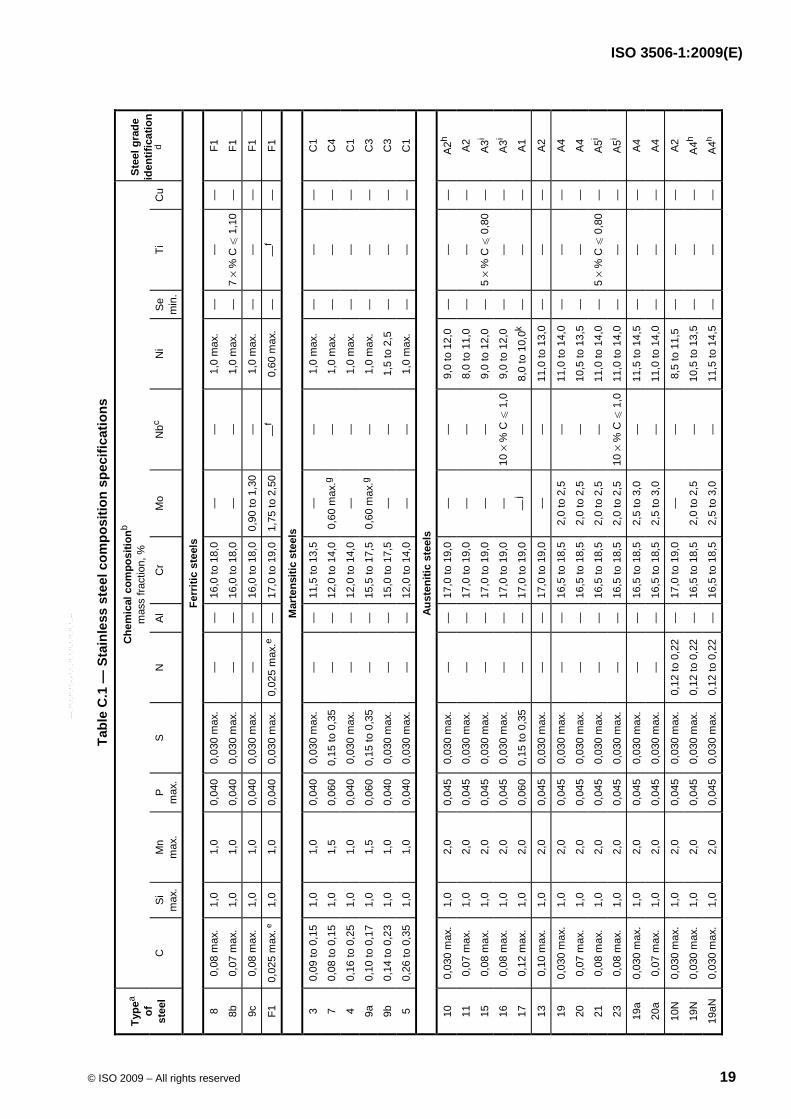
Tabl
e C
.1 —
Sta
inle
ss s
teel
com
posi
tion
spec
ifica
tions
Che
mic
al c
ompo
sitio
nb m
ass
fract
ion,
%
Type
a of
st
eel
C
Si
max
.M
n m
ax.
P
max
. S
N
A
l C
r M
o N
bc N
i S
em
in.
Ti
Cu
Stee
l gra
de
iden
tific
atio
nd
Ferr
itic
stee
ls
8 0,
08 m
ax.
1,0
1,0
0,04
00,
030
max
. —
—
16
,0 to
18,
0—
—
1,
0 m
ax.
—
—
—
F1
8b
0,07
max
. 1,
0 1,
0 0,
040
0,03
0 m
ax.
—
—
16,0
to 1
8,0
—
—
1,0
max
. —
7
× %
C u
1,1
0—
F1
9c
0,08
max
. 1,
0 1,
0 0,
040
0,03
0 m
ax.
—
—
16,0
to 1
8,0
0,90
to 1
,30
—
1,0
max
. —
—
—
F1
F1
0,02
5 m
ax. e
1,0
1,0
0,04
00,
030
max
. 0,
025
max
.e —
17
,0 to
19,
01,
75 to
2,5
0 —
f 0,
60 m
ax.
—
—f
—
F1
Mar
tens
itic
stee
ls
3 0,
09 to
0,1
5 1,
0 1,
0 0,
040
0,03
0 m
ax.
—
—
11,5
to 1
3,5
—
—
1,0
max
. —
—
—
C
1
7 0,
08 to
0,1
5 1,
0 1,
5 0,
060
0,15
to 0
,35
—
—
12,0
to 1
4,0
0,60
max
.g —
1,
0 m
ax.
—
—
—
C4
4 0,
16 to
0,2
5 1,
0 1,
0 0,
040
0,03
0 m
ax.
—
—
12,0
to 1
4,0
—
—
1,0
max
. —
—
—
C
1
9a
0,10
to 0
,17
1,0
1,5
0,06
00,
15 to
0,3
5 —
—
15
,5 to
17,
50,
60 m
ax.g
—
1,0
max
. —
—
—
C
3
9b
0,14
to 0
,23
1,0
1,0
0,04
00,
030
max
. —
—
15
,0 to
17,
5—
—
1,
5 to
2,5
—
—
—
C
3
5 0,
26 to
0,3
5 1,
0 1,
0 0,
040
0,03
0 m
ax.
—
—
12,0
to 1
4,0
—
—
1,0
max
. —
—
—
C
1
Aust
eniti
c st
eels
10
0,03
0 m
ax.
1,0
2,0
0,04
50,
030
max
. —
—
17
,0 to
19,
0—
—
9,
0 to
12,
0 —
—
—
A
2h
11
0,07
max
. 1,
0 2,
0 0,
045
0,03
0 m
ax.
—
—
17,0
to 1
9,0
—
—
8,0
to 1
1,0
—
—
—
A2
15
0,08
max
. 1,
0 2,
0 0,
045
0,03
0 m
ax.
—
—
17,0
to 1
9,0
—
—
9,0
to 1
2,0
—
5 ×
% C
u 0
,80
—
A3i
16
0,08
max
. 1,
0 2,
0 0,
045
0,03
0 m
ax.
—
—
17,0
to 1
9,0
—
10 ×
% C
u 1
,09,
0 to
12,
0 —
—
—
A
3i
17
0,12
max
. 1,
0 2,
0 0,
060
0,15
to 0
,35
—
—
17,0
to 1
9,0
—j
—
8,0
to 1
0,0k
—
—
—
A1
13
0,10
max
. 1,
0 2,
0 0,
045
0,03
0 m
ax.
—
—
17,0
to 1
9,0
—
—
11,0
to 1
3,0
—
—
—
A2
19
0,03
0 m
ax.
1,0
2,0
0,04
50,
030
max
. —
—
16
,5 to
18,
52,
0 to
2,5
—
11
,0 to
14,
0 —
—
—
A
4
20
0,07
max
. 1,
0 2,
0 0,
045
0,03
0 m
ax.
—
—
16,5
to 1
8,5
2,0
to 2
,5
—
10,5
to 1
3,5
—
—
—
A4
21
0,08
max
. 1,
0 2,
0 0,
045
0,03
0 m
ax.
—
—
16,5
to 1
8,5
2,0
to 2
,5
—
11,0
to 1
4,0
—
5 ×
% C
u 0
,80
—
A5i
23
0,08
max
. 1,
0 2,
0 0,
045
0,03
0 m
ax.
—
—
16,5
to 1
8,5
2,0
to 2
,5
10 ×
% C
u 1
,011
,0 to
14,
0 —
—
—
A
5i
19a
0,03
0 m
ax.
1,0
2,0
0,04
50,
030
max
. —
—
16
,5 to
18,
52,
5 to
3,0
—
11
,5 to
14,
5 —
—
—
A
4
20a
0,07
max
. 1,
0 2,
0 0,
045
0,03
0 m
ax.
—
—
16,5
to 1
8,5
2,5
to 3
,0
—
11,0
to 1
4,0
—
—
—
A4
10N
0,
030
max
. 1,
0 2,
0 0,
045
0,03
0 m
ax.
0,12
to 0
,22
—
17,0
to 1
9,0
—
—
8,5
to 1
1,5
—
—
—
A2
19N
0,
030
max
. 1,
0 2,
0 0,
045
0,03
0 m
ax.
0,12
to 0
,22
—
16,5
to 1
8,5
2,0
to 2
,5
—
10,5
to 1
3,5
—
—
—
A4h
19aN
0,
030
max
. 1,
0 2,
0 0,
045
0,03
0 m
ax.
0,12
to 0
,22
—
16,5
to 1
8,5
2,5
to 3
,0
—
11,5
to 1
4,5
—
—
—
A4h
--``,`,,`,,`,`,,`,`,,``,`,-`-`,,`,,`,`,,`---
ISO 3506-1:2009(E)
20 © ISO 2009 – All rights reserved
Tabl
e C
.1 (c
ontin
ued)
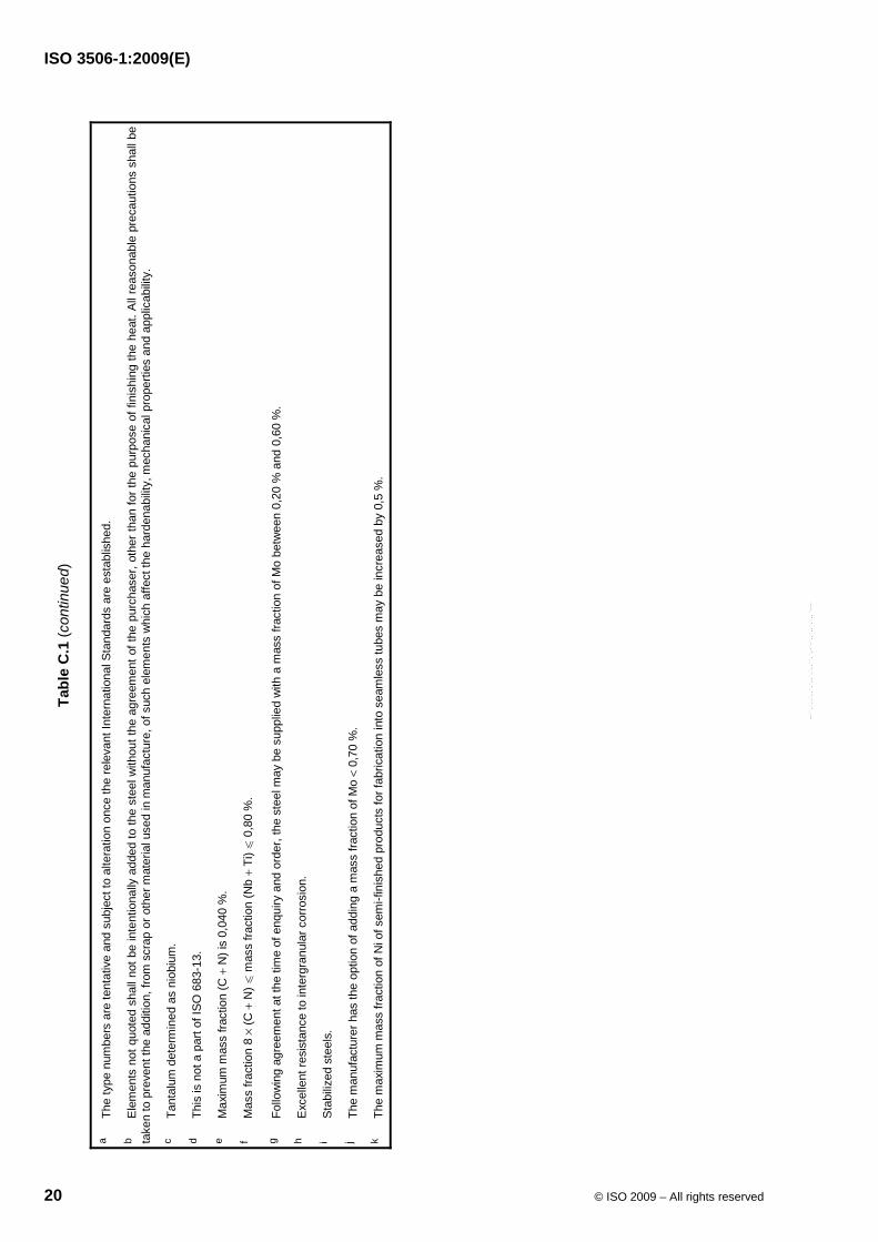
a Th
e ty
pe n
umbe
rs a
re te
ntat
ive
and
subj
ect t
o al
tera
tion
once
the
rele
vant
Inte
rnat
iona
l Sta
ndar
ds a
re e
stab
lishe
d.
b E
lem
ents
not
quo
ted
shal
l not
be
inte
ntio
nally
add
ed to
the
stee
l with
out t
he a
gree
men
t of t
he p
urch
aser
, oth
er th
an fo
r the
pur
pose
of f
inis
hing
the
heat
. All
reas
onab
le p
reca
utio
ns s
hall
be
take
n to
pre
vent
the
addi
tion,
from
scr
ap o
r oth
er m
ater
ial u
sed
in m
anuf
actu
re, o
f suc
h el
emen
ts w
hich
affe
ct th
e ha
rden
abilit
y, m
echa
nica
l pro
perti
es a
nd a
pplic
abilit
y.
c Ta
ntal
um d
eter
min
ed a
s ni
obiu
m.
d Th
is is
not
a p
art o
f ISO
683
-13.
e M
axim
um m
ass
fract
ion
(C +
N) i
s 0,
040
%.
f M
ass
fract
ion
8 ×
(C +
N) u
mas
s fra
ctio
n (N
b +
Ti) u
0,8
0 %
.
g Fo
llow
ing
agre
emen
t at t
he ti
me
of e
nqui
ry a
nd o
rder
, the
ste
el m
ay b
e su
pplie
d w
ith a
mas
s fra
ctio
n of
Mo
betw
een
0,20
% a
nd 0
,60
%.
h E
xcel
lent
resi
stan
ce to
inte
rgra
nula
r cor
rosi
on.
i S
tabi
lized
ste
els.
j Th
e m
anuf
actu
rer h
as th
e op
tion
of a
ddin
g a
mas
s fra
ctio
n of
Mo
< 0,
70 %
.
k Th
e m
axim
um m
ass
fract
ion
of N
i of s
emi-f
inis
hed
prod
ucts
for f
abric
atio
n in
to s
eam
less
tube
s m
ay b
e in
crea
sed
by 0
,5 %
.
--``,`,,`,,`,`,,`,`,,``,`,-`-`,,`,,`,`,,`---
ISO 3506-1:2009(E)
© ISO 2009 – All rights reserved 21
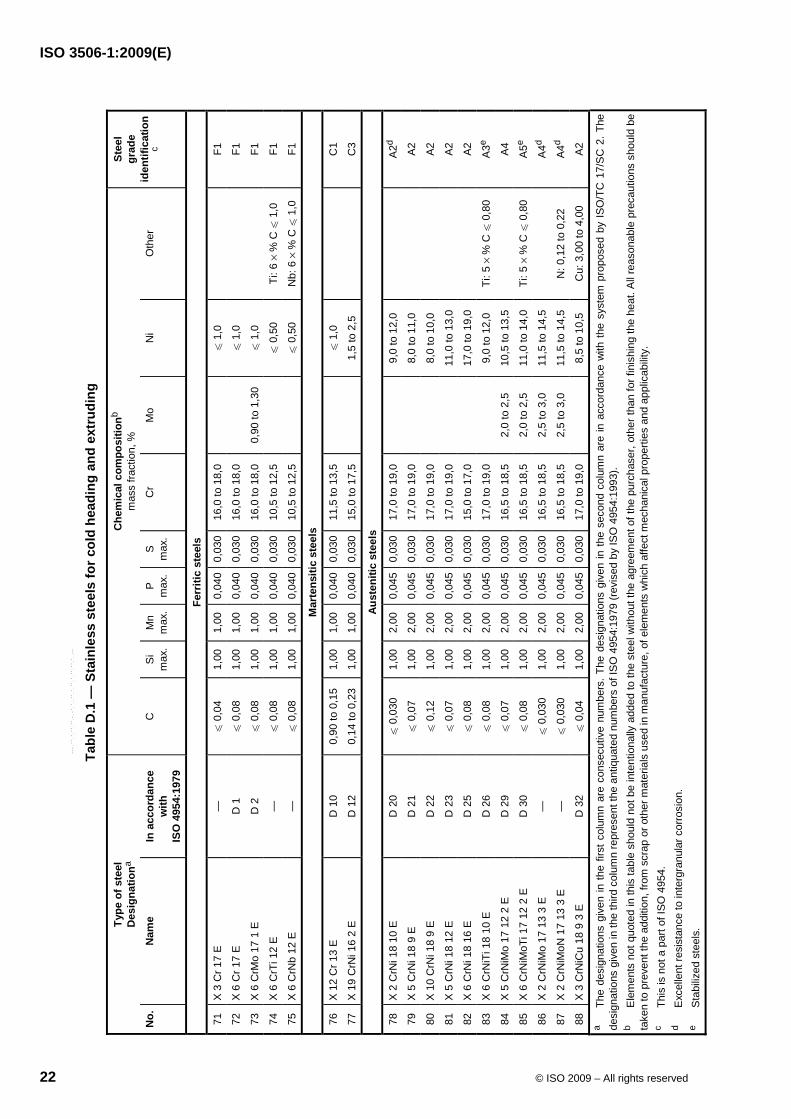
Annex D (informative)
Stainless steels for cold heading and extruding
(Extract from ISO 4954:1993)
--``,`,,`,,`,`,,`,`,,``,`,-`-`,,`,,`,`,,`---
ISO 3506-1:2009(E)
22 © ISO 2009 – All rights reserved
Tabl
e D
.1 —
Sta
inle
ss s
teel
s fo
r col
d he
adin
g an
d ex
trud
ing
Type
of s
teel
D
esig
natio
na C
hem
ical
com
posi
tionb
m
ass
fract
ion,
%
No.
N
ame
In a
ccor
danc
e w
ith
ISO
495
4:19
79
C
Si
max
. M
nm
ax.
P
max
. S
m
ax.
Cr
Mo
Ni
Oth
er
Stee
l gr
ade
iden
tific
atio
n c
Ferr
itic
stee
ls
71
X 3
Cr 1
7 E
—
u
0,0
4 1,
00
1,00
0,
040
0,03
016
,0 to
18,
0
u 1
,0
F1
72
X 6
Cr 1
7 E
D
1
u 0
,08
1,00
1,
00
0,04
00,
030
16,0
to 1
8,0
u
1,0
F1
73
X 6
CrM
o 17
1 E
D
2
u 0
,08
1,00
1,
00
0,04
00,
030
16,0
to 1
8,0
0,90
to 1
,30
u 1
,0
F1
74
X 6
CrT
i 12
E
—
u 0
,08
1,00
1,
00
0,04
00,
030
10,5
to 1
2,5
u
0,5
0 Ti
: 6 ×
% C
u 1
,0
F1
75
X 6
CrN
b 12
E
—
u 0
,08
1,00
1,
00
0,04
00,
030
10,5
to 1
2,5
u
0,5
0 N
b: 6
× %
C u
1,0
F1
Mar
tens
itic
stee
ls
76
X 12
Cr 1
3 E
D
10
0,90
to 0
,15
1,00
1,
00
0,04
00,
030
11,5
to 1
3,5
u
1,0
C1
77
X 19
CrN
i 16
2 E
D
12
0,14
to 0
,23
1,00
1,
00
0,04
00,
030
15,0
to 1
7,5
1,
5 to
2,5
C3
Aust
eniti
c st
eels
78
X 2
CrN
i 18
10 E
D
20
u 0
,030
1,
00
2,00
0,
045
0,03
017
,0 to
19,
0
9,0
to 1
2,0
A
2d
79
X 5
CrN
i 18
9 E
D
21
u 0
,07
1,00
2,
00
0,04
50,
030
17,0
to 1
9,0
8,
0 to
11,
0
A2
80
X 10
CrN
i 18
9 E
D
22
u 0
,12
1,00
2,
00
0,04
50,
030
17,0
to 1
9,0
8,
0 to
10,
0
A2
81
X 5
CrN
i 18
12 E
D
23
u 0
,07
1,00
2,
00
0,04
50,
030
17,0
to 1
9,0
11
,0 to
13,
0
A2
82
X 6
CrN
i 18
16 E
D
25
u 0
,08
1,00
2,
00
0,04
50,
030
15,0
to 1
7,0
17
,0 to
19,
0
A2
83
X 6
CrN
iTi 1
8 10
E
D 2
6 u
0,0
8 1,
00
2,00
0,
045
0,03
017
,0 to
19,
0
9,0
to 1
2,0
Ti: 5
× %
C u
0,8
0 A
3e
84
X 5
CrN
iMo
17 1
2 2
E
D 2
9 u
0,0
7 1,
00
2,00
0,
045
0,03
016
,5 to
18,
5 2,
0 to
2,5
10
,5 to
13,
5
A4
85
X 6
CrN
iMoT
i 17
12 2
E
D 3
0 u
0,0
8 1,
00
2,00
0,
045
0,03
016
,5 to
18,
5 2,
0 to
2,5
11
,0 to
14,
0 Ti
: 5 ×
% C
u 0
,80
A5e
86
X 2
CrN
iMo
17 1
3 3
E
—
u 0
,030
1,
00
2,00
0,
045
0,03
016
,5 to
18,
5 2,
5 to
3,0
11
,5 to
14,
5
A4d
87
X 2
CrN
iMoN
17
13 3
E
—
u 0
,030
1,
00
2,00
0,
045
0,03
016
,5 to
18,
5 2,
5 to
3,0
11
,5 to
14,
5 N
: 0,1
2 to
0,2
2 A
4d
88
X 3
CrN
iCu
18 9
3 E
D
32
u 0
,04
1,00
2,
00
0,04
50,
030
17,0
to 1
9,0
8,
5 to
10,
5 C
u: 3
,00
to 4
,00
A2
a Th
e de
sign
atio
ns g
iven
in th
e fir
st c
olum
n ar
e co
nsec
utiv
e nu
mbe
rs. T
he d
esig
natio
ns g
iven
in th
e se
cond
col
umn
are
in a
ccor
danc
e w
ith th
e sy
stem
pro
pose
d by
ISO
/TC
17/
SC
2. T
he
desi
gnat
ions
giv
en in
the
third
col
umn
repr
esen
t the
ant
iqua
ted
num
bers
of I
SO
495
4:19
79 (r
evis
ed b
y IS
O 4
954:
1993
). b
Ele
men
ts n
ot q
uote
d in
this
tabl
e sh
ould
not
be
inte
ntio
nally
add
ed to
the
stee
l with
out t
he a
gree
men
t of t
he p
urch
aser
, oth
er th
an fo
r fin
ishi
ng th
e he
at. A
ll re
ason
able
pre
caut
ions
sho
uld
be
take
n to
pre
vent
the
addi
tion,
from
scr
ap o
r oth
er m
ater
ials
use
d in
man
ufac
ture
, of e
lem
ents
whi
ch a
ffect
mec
hani
cal p
rope
rties
and
app
licab
ility.
c
This
is n
ot a
par
t of I
SO 4
954.
d
Exc
elle
nt re
sist
ance
to in
terg
ranu
lar c
orro
sion
. e
Sta
biliz
ed s
teel
s.
--``,`,,`,,`,`,,`,`,,``,`,-`-`,,`,,`,`,,`---
ISO 3506-1:2009(E)
© ISO 2009 – All rights reserved 23
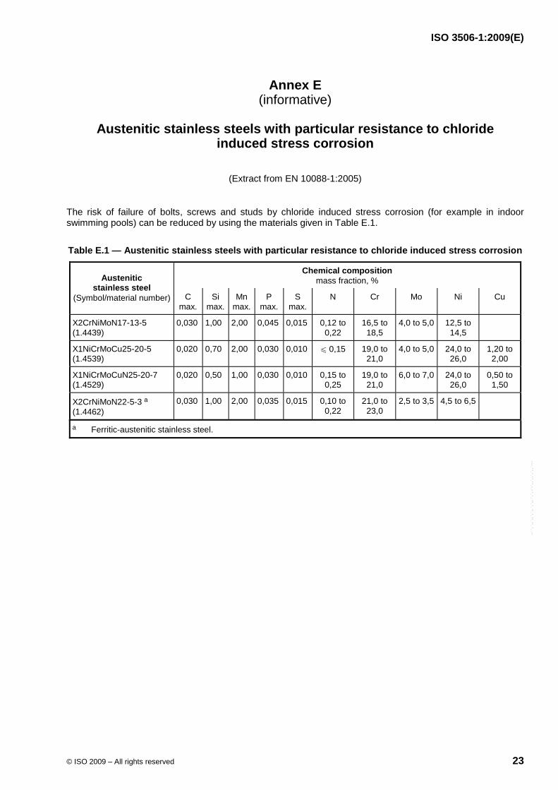
Annex E (informative)
Austenitic stainless steels with particular resistance to chloride
induced stress corrosion
(Extract from EN 10088-1:2005)
The risk of failure of bolts, screws and studs by chloride induced stress corrosion (for example in indoor swimming pools) can be reduced by using the materials given in Table E.1.
Table E.1 — Austenitic stainless steels with particular resistance to chloride induced stress corrosion
Chemical composition mass fraction, % Austenitic
stainless steel (Symbol/material number) C
max. Si
max. Mn
max.P
max. S
max. N Cr Mo Ni Cu
X2CrNiMoN17-13-5 (1.4439)
0,030 1,00 2,00 0,045 0,015 0,12 to 0,22
16,5 to 18,5
4,0 to 5,0 12,5 to 14,5
X1NiCrMoCu25-20-5 (1.4539)
0,020 0,70 2,00 0,030 0,010 u 0,15 19,0 to 21,0
4,0 to 5,0 24,0 to 26,0
1,20 to 2,00
X1NiCrMoCuN25-20-7 (1.4529)
0,020 0,50 1,00 0,030 0,010 0,15 to 0,25
19,0 to 21,0
6,0 to 7,0 24,0 to 26,0
0,50 to 1,50
X2CrNiMoN22-5-3 a (1.4462)
0,030 1,00 2,00 0,035 0,015 0,10 to 0,22
21,0 to 23,0
2,5 to 3,5 4,5 to 6,5
a Ferritic-austenitic stainless steel.
--``,`,,`,,`,`,,`,`,,``,`,-`-`,,`,,`,`,,`---
ISO 3506-1:2009(E)
24 © ISO 2009 – All rights reserved
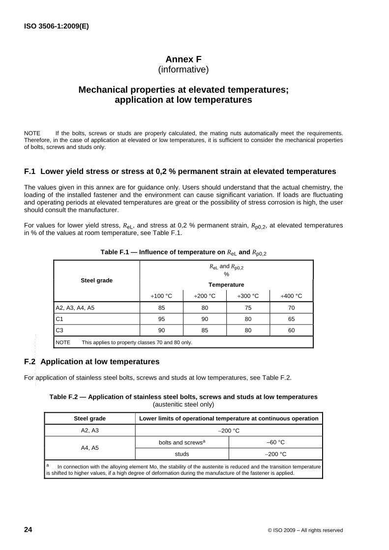
Annex F (informative)
Mechanical properties at elevated temperatures;
application at low temperatures
NOTE If the bolts, screws or studs are properly calculated, the mating nuts automatically meet the requirements. Therefore, in the case of application at elevated or low temperatures, it is sufficient to consider the mechanical properties of bolts, screws and studs only.
F.1 Lower yield stress or stress at 0,2 % permanent strain at elevated temperatures
The values given in this annex are for guidance only. Users should understand that the actual chemistry, the loading of the installed fastener and the environment can cause significant variation. If loads are fluctuating and operating periods at elevated temperatures are great or the possibility of stress corrosion is high, the user should consult the manufacturer.
For values for lower yield stress, ReL, and stress at 0,2 % permanent strain, Rp0,2, at elevated temperatures in % of the values at room temperature, see Table F.1.
Table F.1 — Influence of temperature on ReL and Rp0,2
ReL and Rp0,2 %
Temperature Steel grade
+100 °C +200 °C +300 °C +400 °C
A2, A3, A4, A5 85 80 75 70
C1 95 90 80 65
C3 90 85 80 60
NOTE This applies to property classes 70 and 80 only.
F.2 Application at low temperatures
For application of stainless steel bolts, screws and studs at low temperatures, see Table F.2.
Table F.2 — Application of stainless steel bolts, screws and studs at low temperatures (austenitic steel only)
Steel grade Lower limits of operational temperature at continuous operation
A2, A3 −200 °C
bolts and screwsa −60 °C A4, A5
studs −200 °C
a In connection with the alloying element Mo, the stability of the austenite is reduced and the transition temperature is shifted to higher values, if a high degree of deformation during the manufacture of the fastener is applied.
--``,`,,`,,`,`,,`,`,,``,`,-`-`,,`,,`,`,,`---
ISO 3506-1:2009(E)
© ISO 2009 – All rights reserved 25
Annex G (informative)
Time-temperature diagram of intergranular corrosion in austenitic
stainless steels, grade A2 (18/8 steels)
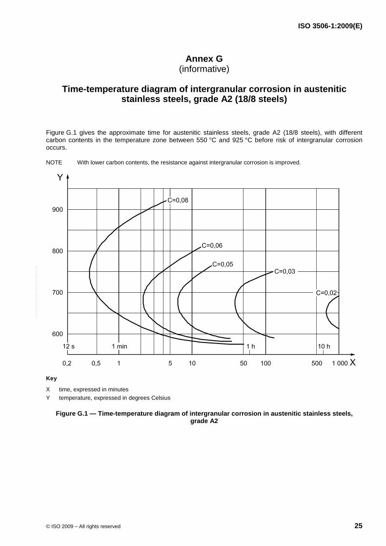
Figure G.1 gives the approximate time for austenitic stainless steels, grade A2 (18/8 steels), with different carbon contents in the temperature zone between 550 °C and 925 °C before risk of intergranular corrosion occurs.
NOTE With lower carbon contents, the resistance against intergranular corrosion is improved.
Key
X time, expressed in minutes Y temperature, expressed in degrees Celsius
Figure G.1 — Time-temperature diagram of intergranular corrosion in austenitic stainless steels, grade A2
--``,`,,`,,`,`,,`,`,,``,`,-`-`,,`,,`,`,,`---
ISO 3506-1:2009(E)
26 © ISO 2009 – All rights reserved
Annex H (informative)
Magnetic properties for austenitic stainless steels
Where specific magnetic properties are required, an experienced metallurgist should be consulted.
All austenitic stainless steel fasteners are normally non-magnetic; after cold working, it is possible for some magnetic properties to be evident.
Each material is characterized by its ability to be magnetized, which applies even to stainless steel. It is only possible for a vacuum to be entirely non-magnetic. The measure of the material's permeability in a magnetic field is the permeability value µr for that material in relation to a vacuum. The material has low permeability if µr becomes close to 1.
EXAMPLE 1 A2: µr ≈ 1,8
EXAMPLE 2 A4: µr ≈ 1,015
EXAMPLE 3 A4L: µr ≈ 1,005
EXAMPLE 4 F1: µr ≈ 5
--``,`,,`,,`,`,,`,`,,``,`,-`-`,,`,,`,`,,`---
ISO 3506-1:2009(E)
© ISO 2009 – All rights reserved 27
Bibliography
[1] ISO 683-13:19863), Heat-treatable steels, alloy steels and free cutting steels — Part 13: Wrought stainless steels
[2] ISO 724, ISO general-purpose metric screw threads — Basic dimensions
[3] ISO 4954:1993, Steels for cold heading and cold extruding
[4] ISO 8044, Corrosion of metals and alloys — Basic terms and definitions
[5] EN 10088-1:2005, Stainless steels — Part 1: List of stainless steels
3) International Standard withdrawn.
--``,`,,`,,`,`,,`,`,,``,`,-`-`,,`,,`,`,,`---
ISO 3506-1:2009(E)
ICS 21.060.10 Price based on 27 pages
© ISO 2009 – All rights reserved
--``,`,,`,,`,`,,`,`,,``,`,-`-`,,`,,`,`,,`---