Embed Size (px)
Citation preview
Internet Infrastructure Security
Fall 2003
Simon Fraser University
ENSC 835
Scott Wakelin
Internet Infrastructure Security
- 1 -
Revision History Issue No.
Issue Date Details of Change
1 October 2003
Document Created. Draft.
2 December, 2003
Final Submission.
Internet Infrastructure Security
- 2 -
Table of Contents Revision History .............................................................................................................................1
Table of Contents ...........................................................................................................................2
List of Figures ................................................................................................................................4
1 Abstract ...................................................................................................................................7
1.1 Glossary.........................................................................................................................8
2 Introduction............................................................................................................................10
3 Internet Infrastructure ............................................................................................................ 11
3.1 Internet Service Provider (ISP) Networks....................................................................12
3.2 Interconnecting ISP’s...................................................................................................16
4 Internet Routing.....................................................................................................................18
4.1 Open Shorted Path First (OSPF) ................................................................................19
4.1.1 OSPF Operation..........................................................................................20
4.1.2 OSPF Packet Types ....................................................................................20
4.1.3 The OSPF Packet Authentication Field.......................................................22
4.1.4 External Route Distribution .........................................................................22
4.2 Border Gateway Protocol (BGP) .................................................................................23
4.2.1 BGP Operation ............................................................................................24
4.2.2 BGP Packet Formats...................................................................................25
4.2.3 Route Aggregation.......................................................................................27
5 Internet Infrastructure Security..............................................................................................28
5.1 Internet Infrastructure Weaknesses ............................................................................28
5.1.1 DNS Hacking...............................................................................................29
5.1.2 Packet Mistreatment ...................................................................................29
5.1.3 Denial of Service .........................................................................................30
5.1.4 Routing Table Poisoning..............................................................................31
5.2 Internet Infrastructure Security Solutions ....................................................................33
5.2.1 Secure-BGP (S-BGP)..................................................................................33
5.3 Link Cutting Attacks .....................................................................................................36
5.3.1 Link Cutting Example ..................................................................................36
6 Experimental Results ............................................................................................................39
6.1 Route Table Poisoning Demonstration ........................................................................39
6.1.1 OSPF Simple Topology – Normal Case......................................................39
6.1.2 OSPF Simple Topology – Router 3 Faulty ..................................................41
6.1.3 OSPF Expanded Topology – Normal case..................................................42
6.1.4 OSPF Expanded Topology – Faulty Case...................................................44
Internet Infrastructure Security
- 3 -
6.2 Link Cutting Demonstration .........................................................................................46
6.2.1 Link Cutting: Attacker on Path.....................................................................48
6.2.2 Link Cutting: Attacker Not on Path ..............................................................49
7 Future Work...........................................................................................................................52
8 References ............................................................................................................................53
9 Appendix – Link Cutting TcL Code ........................................................................................54
Internet Infrastructure Security
- 4 -
List of Figures Figure 1 Providing connectivity between Host A and Host B on different
networks ................................................................................................................................11
Figure 2 Typical corporate network ............................................................................................12
Figure 3 Typical subscriber to ISP connection ...........................................................................13
Figure 4 Simple ISP POP ...........................................................................................................13
Figure 5 An actual POP: Sprintlink Frankfurt..............................................................................14
Figure 6 Sample interconnection of an ISP’s POP’s ..................................................................15
Figure 7 AT&T’s backbone network............................................................................................16
Figure 8 Interconnecting ISP’s at an Internet Exchange Point...................................................17
Figure 9 Intra- and Inter-AS Routing...........................................................................................18
Figure 10 OSPF Areas and Router types...................................................................................19
Figure 11 OSPF Header .............................................................................................................21
Figure 12 Format of Link State Advertisement packets..............................................................21
Figure 13 Re-definition of the OSPF Authentication Data field ..................................................22
Figure 14 BGP Internetwork .......................................................................................................24
Figure 15 BGP Common Header................................................................................................25
Figure 16 BGP Open Message format .......................................................................................26
Figure 17 BGP Update Message format ....................................................................................26
Figure 18 Normal Routing Scenario ...........................................................................................29
Figure 19 Loop Formation Due to Packet Mistreatment.............................................................30
Figure 20 OSPF Network: Normal Scenario...............................................................................32
Figure 21 OSPF Network: Router Attack Scenario ....................................................................32
Figure 22 Redefinition of the BGP Update message..................................................................35
Figure 23 Link Cutting: Normal Scenario....................................................................................37
Figure 24 Link Cutting: Attack Scenario .....................................................................................38
Figure 25 OSPF Simple Topology, Normal Case.......................................................................39
Figure 26 Router 1 Routing table, Normal case .........................................................................40
Figure 27 Gateway0 to Gateway 1 Route ..................................................................................41
Figure 28 Router 1 Routing table, Router 3 Faulty.....................................................................41
Figure 29 Gateway0 to Gateway 1 Route, Router 3 Faulty........................................................42
Figure 30 OSPF Expanded Topology, Normal Case..................................................................43
Figure 31 OSPF Expanded Topology, Normal Case Link Utilization .........................................44
Figure 32 OSPF Expanded Topology, Faulty Case Link Utilization ...........................................45
Figure 33 Router 5 Queuing Delay Comparison ........................................................................46
Figure 34 NS-2 Link Cutting Demonstration Topology...............................................................47
Internet Infrastructure Security
- 5 -
Figure 35 NS-2 Traffic Flow with Attacker on Path......................................................................49
Figure 36 Initial Traffic Flow from Router 0 to Router 12 ...........................................................50
Figure 37 Traffic Flow After Links Cut .........................................................................................51
Internet Infrastructure Security
- 6 -
List of Tables Table 1 Glossary of Terms ............................................................................................................8
Table 2 Access versus Backbone Routers..................................................................................14
Table 3 OSPF Simple Topology, Link Costs ...............................................................................40
Table 4 Demand Summary..........................................................................................................42
Table 5 Link Utilization Encodings...............................................................................................43
Table 6 Demand Summary – Faulty Case ..................................................................................44
Internet Infrastructure Security
- 7 -
1 Abstract
Increasingly, critical infrastructure such as banking systems, water treatment facilities, and military installations are using the Internet as a means to increase productivity, and as a transport mechanism. At the same time, weaknesses in the routing protocols are being exploited at an increasing rate. Neither OSPF nor BGP offer real security against the determined hacker, in part due to the implicit trust relationship each router shares with one another.
This paper also discussed one of the proposed routing protocol security solutions, Secure-BGP.
OPNET was used to demonstrate the effects of a link cutting attack, and the ease by which a faulty or hijacked router could enable packet mis-direction or worse, outright corruption.
Ideas for future work are also presented.
Please note, it is not the goal of this paper nor the project it is based on to attempt to implement any of the proposed solutions.
Internet Infrastructure Security
- 8 -
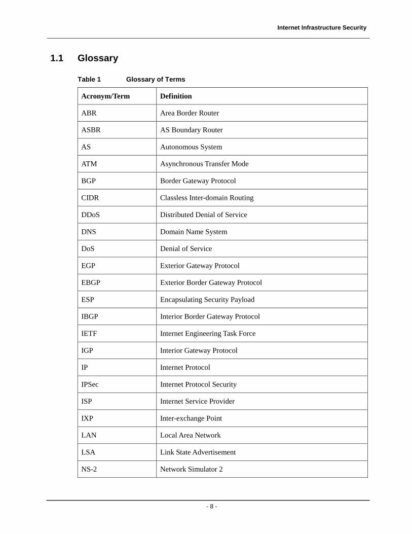
1.1 Glossary
Table 1 Glossary of Terms
Acronym/Term Definition
ABR Area Border Router
ASBR AS Boundary Router
AS Autonomous System
ATM Asynchronous Transfer Mode
BGP Border Gateway Protocol
CIDR Classless Inter-domain Routing
DDoS Distributed Denial of Service
DNS Domain Name System
DoS Denial of Service
EGP Exterior Gateway Protocol
EBGP Exterior Border Gateway Protocol
ESP Encapsulating Security Payload
IBGP Interior Border Gateway Protocol
IETF Internet Engineering Task Force
IGP Interior Gateway Protocol
IP Internet Protocol
IPSec Internet Protocol Security
ISP Internet Service Provider
IXP Inter-exchange Point
LAN Local Area Network
LSA Link State Advertisement
NS-2 Network Simulator 2
Internet Infrastructure Security
- 9 -
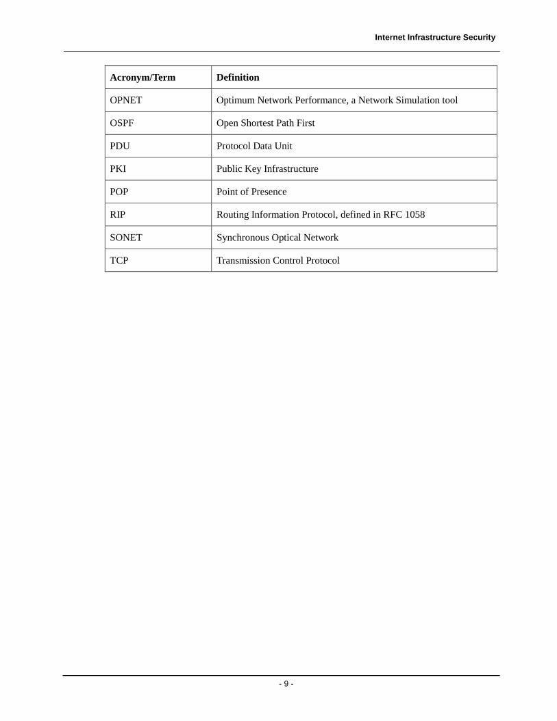
Acronym/Term Definition
OPNET Optimum Network Performance, a Network Simulation tool
OSPF Open Shortest Path First
PDU Protocol Data Unit
PKI Public Key Infrastructure
POP Point of Presence
RIP Routing Information Protocol, defined in RFC 1058
SONET Synchronous Optical Network
TCP Transmission Control Protocol
Internet Infrastructure Security
- 10 -
2 Introduction
Over the past two decades, the Internet has evolved from its research-oriented roots to the ubiquitous network we know today that is accessed daily by hundreds of millions of people in all corners of the globe. We are all familiar with the most popular uses of the Internet, from email to web surfing. Increasingly, critical infrastructure such as power plants and water treatment facilities are becoming “Internet-enabled”. However, while protocol suites (such as IPSec) were developed to protect user-data, little was done to protect the actual infrastructure this data was carried over. Hackers and cyber-terrorists have noticed this, and have launched increasing attacks.
This research projects begins with a discussion of the Internet infrastructure itself, including:
• Typical subscriber to provider networks
• Design of a typical Internet Service Provider (ISP) Point of Presence (POP)
• Typical ISP to ISP interconnections
• Network hierarchy
• Intra-domain routing with OSPF
• Inter-domain routing with BGP
• Routing policy
Once the basic architecture and infrastructure of the Internet is understood, the security risks inherent in today’s networks will be examined. OPNET and NS-2 will be used to demonstrate some of the security holes.
This project will include a discussion of one of the counter-measures being developed to secure the Internet infrastructure, Secure-BGP.
Internet Infrastructure Security
- 11 -
3 Internet Infrastructure
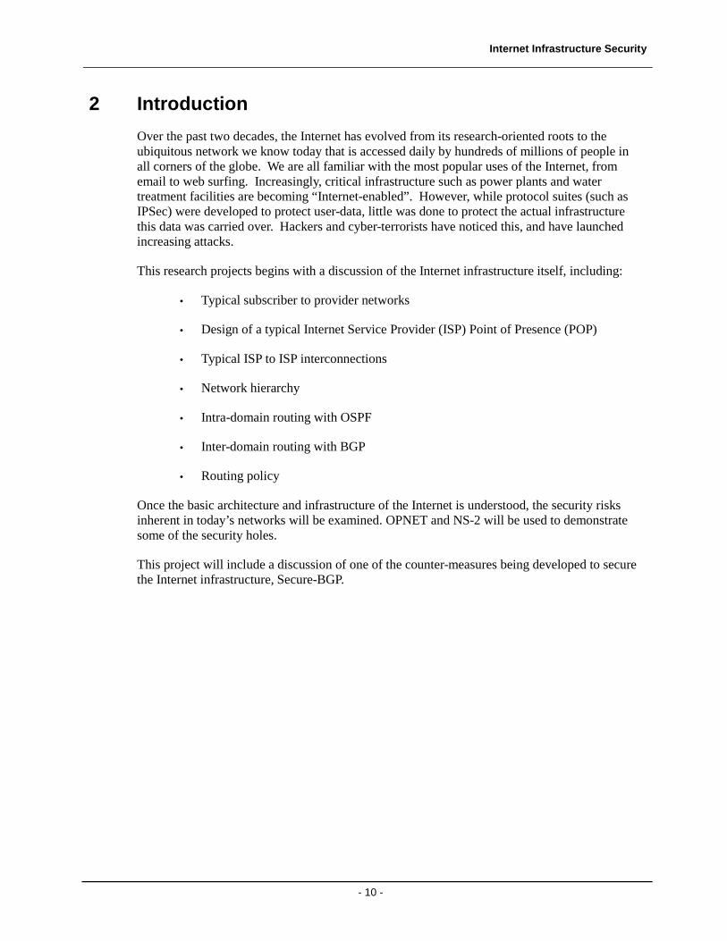
The Internet can be considered a network of networks, interconnected in such a way as to allow packets originating in one network to be transported to a different network. This ‘different’ network is often not only running different protocols, but is also not necessarily connected to the originating network. It is the primary function of the network layer (most often running IP – Internet Protocol) to enable network A’s packets to reach network B. The primary network element that provides such connectivity is the router. Figure 1 provides a simple conceptualization of how packets originating from Host A traverse network A to Router R which re-directs them to Network B and eventually Host B.
Figure 1 Providing connectivity between Host A and Host B on different networks
An IP packet (which would be encapsulating some high layer PDU) contains a source and destination IP address. The source IP address is the address of Host A, while the destination IP address is that of Host B. When Host A decides it must send this packet to Host B, it first references its forwarding database to determine if the destination is directly connected (i.e. on the same network or network segment). If the two hosts were co-located, host A would simply send the packet to the MAC address corresponding to Host B.
However, in this example, the two Hosts are not co-located. Therefore, the IP implementation in Host A looks up the ‘next hop’, the IP address of a router that is ‘closer’ to Host B (in this case, Router R). Host A then sends the packet to Router R using Router R’s MAC address that is on the same network segment as Host A.
Router R then accesses it routing table to determine what to do with the packet. In this simple example, Host B happens to be on the same network segment as one of Router R’s interfaces. Therefore, Router R simply forwards the packet using Host B’s MAC address.
Application
Transport(TCP)
Network (IP)
Link
PHY
Host A
Application
Transport(TCP)
Network (IP)
Link
PHY
Host B
Network (IP)
Link
PHY
Router R
Network A Network B
Internet Infrastructure Security
- 12 -
It should be noted that the Address Resolution Protocol (ARP) is the method used by the hosts and routers to:
1. Associate a MAC address with a particular IP address
2. Build the associated IP forwarding database
ARP, though a critical element is connectionless datagram networking, is outside the scope of this paper.
3.1 Internet Service Provider (ISP) Networks
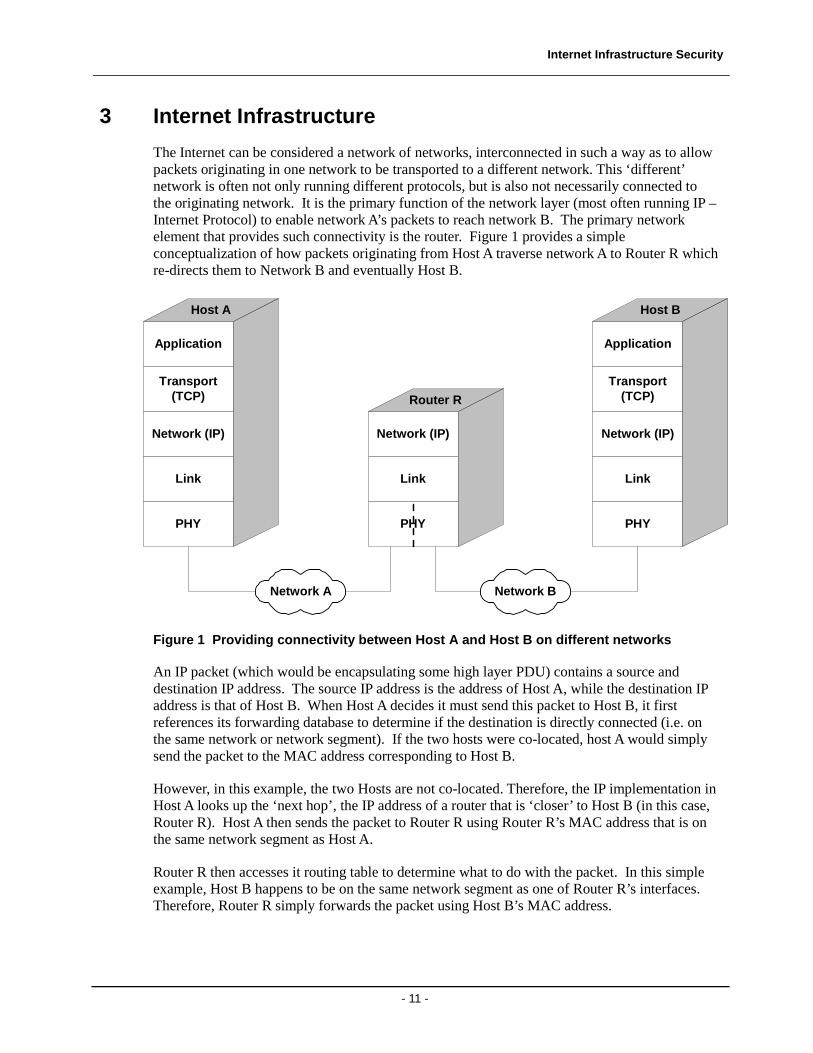
The previous discussion focused on the simple case of transferring of a packet from one router to another, whether these routers are within a corporate LAN, or an ISP Point of Presence (POP). Figure 2 shows a simplified view of a corporate network. The firewall/gateway appliance acts as the interface to the larger corporate LAN with hosts (computers) distributed throughout the topology.
Computer
Computer
Router
Computer
Computer
LAN Segment A LAN Segment B
Computer
Firewall/Gateway
LAN
Seg
men
t C
Computer
Figure 2 Typical corporate network
This corporate customer would then subscribe to network services provided by an Internet Service Provider. The type of connection between subscriber and ISP is governed by many factors, including:
• Required access rate (i.e. the data rate)
• Available access technologies (frame relay, ATM, Ethernet, etc)
• Cost
• Type of subscriber network
Internet Infrastructure Security
- 13 -
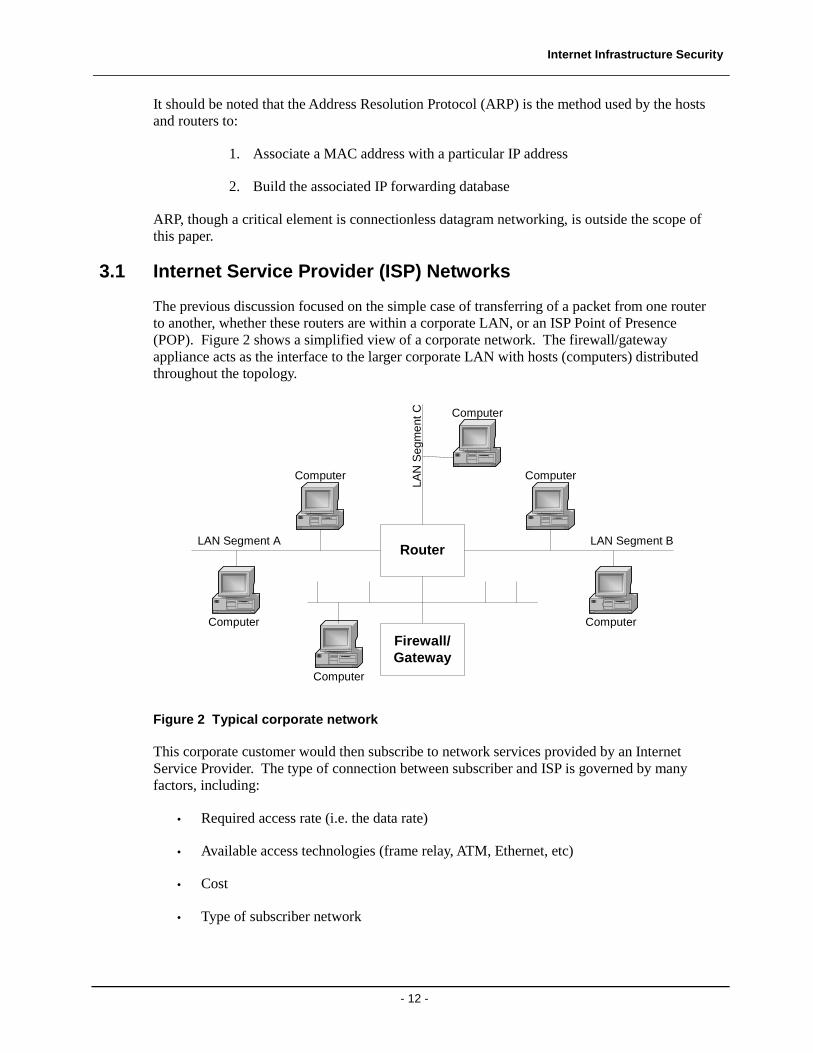
Figure 3 shows a typical ISP POP to Subscriber network [14]. Details of the metro SONET ring, such as the Add/Drop Multiplexers are beyond the scope of this paper.
ADM
OC-48OC-48
GE
DS3
OC-3
OC-12Metro SONET Ring
OC-192/STM64
NetworkA
NetworkB
NetworkC
Figure 3 Typical subscriber to ISP connection
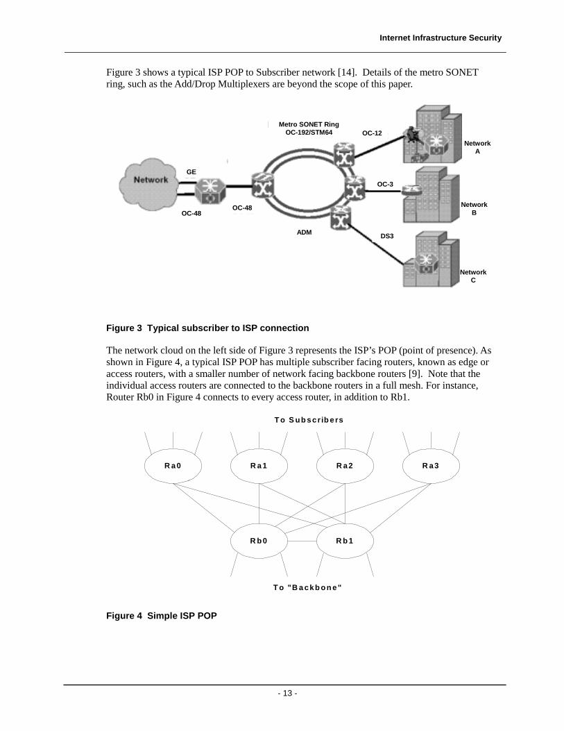
The network cloud on the left side of Figure 3 represents the ISP’s POP (point of presence). As shown in Figure 4, a typical ISP POP has multiple subscriber facing routers, known as edge or access routers, with a smaller number of network facing backbone routers [9]. Note that the individual access routers are connected to the backbone routers in a full mesh. For instance, Router Rb0 in Figure 4 connects to every access router, in addition to Rb1.
R b 0
R a0 R a 1 R a2 R a3
R b 1
T o S u b scrib ers
T o "B a ckb on e"
Figure 4 Simple ISP POP
Internet Infrastructure Security
- 14 -
The access routers in Figure 4 connect to the various ISP’s customers, while the backbone routers connect to other POP’s of the ISP. Note that links interconnecting access and backbone routers (i.e. Ra0 and Rb0) is of a lower data rate than those connecting backbone routers (i.e. Rb0 and Rb1). Therefore, it is undesirable to have traffic traversing from one backbone router to another to do so via an access or intermediate router. These routes are typically set to a high cost to prevent their use.
Table 2 presents a summary of the differences between the two types of routers.
Table 2 Access versus Backbone Routers
Access Router Backbone Router Packet Throughput High Modest Packet Processing (i.e. services offered)
Minimal High touch feature set
Interface types Modest number of very high speed interfaces
Large number of relatively low speed interfaces
Traffic patterns Any interface to any interface Typically from subscriber to backbone
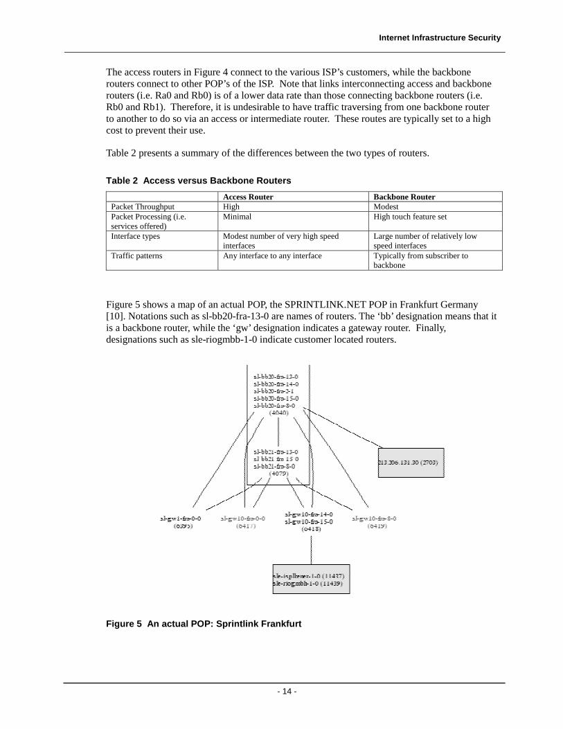
Figure 5 shows a map of an actual POP, the SPRINTLINK.NET POP in Frankfurt Germany [10]. Notations such as sl-bb20-fra-13-0 are names of routers. The ‘bb’ designation means that it is a backbone router, while the ‘gw’ designation indicates a gateway router. Finally, designations such as sle-riogmbb-1-0 indicate customer located routers.
Figure 5 An actual POP: Sprintlink Frankfurt
Internet Infrastructure Security
- 15 -
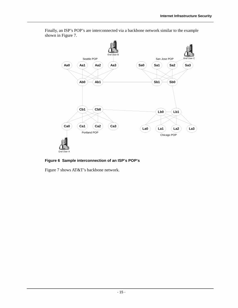
Finally, an ISP’s POP’s are interconnected via a backbone network similar to the example shown in Figure 7.
Figure 6 Sample interconnection of an ISP’s POP’s
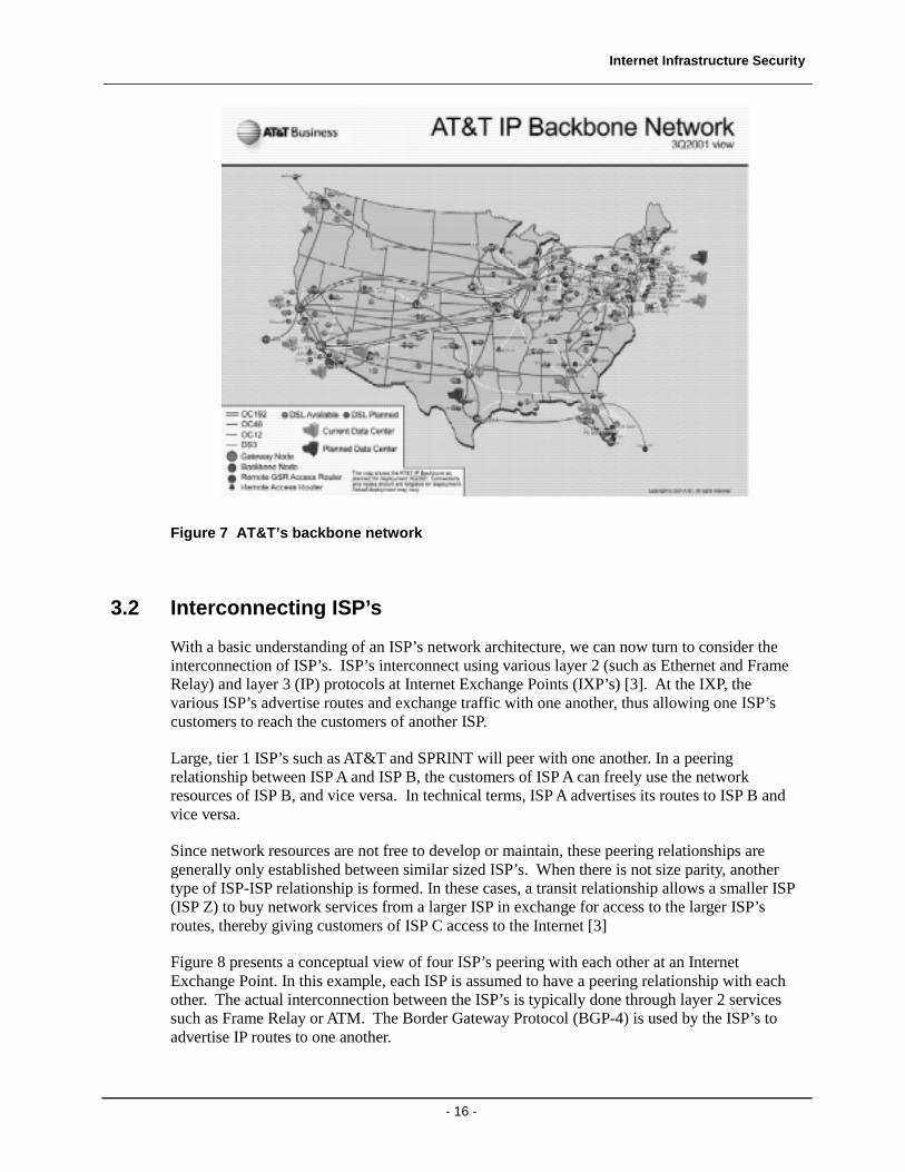
Figure 7 shows AT&T’s backbone network.
Ab0
Aa0 Aa1 Aa2 Aa3
Ab1
Seattle POP
Sb1
Sa0 Sa1 Sa2 Sa3
Sb0
San Jose POP
Cb1
Ca0 Ca1 Ca2 Ca3
Cb0
Portland POP
Lb0
La0 La1 La2 La3
Lb1
Chicago POP
End User A
End User B
End User C
Internet Infrastructure Security
- 16 -
Figure 7 AT&T’s backbone network
3.2 Interconnecting ISP’s
With a basic understanding of an ISP’s network architecture, we can now turn to consider the interconnection of ISP’s. ISP’s interconnect using various layer 2 (such as Ethernet and Frame Relay) and layer 3 (IP) protocols at Internet Exchange Points (IXP’s) [3]. At the IXP, the various ISP’s advertise routes and exchange traffic with one another, thus allowing one ISP’s customers to reach the customers of another ISP.
Large, tier 1 ISP’s such as AT&T and SPRINT will peer with one another. In a peering relationship between ISP A and ISP B, the customers of ISP A can freely use the network resources of ISP B, and vice versa. In technical terms, ISP A advertises its routes to ISP B and vice versa.
Since network resources are not free to develop or maintain, these peering relationships are generally only established between similar sized ISP’s. When there is not size parity, another type of ISP-ISP relationship is formed. In these cases, a transit relationship allows a smaller ISP (ISP Z) to buy network services from a larger ISP in exchange for access to the larger ISP’s routes, thereby giving customers of ISP C access to the Internet [3]
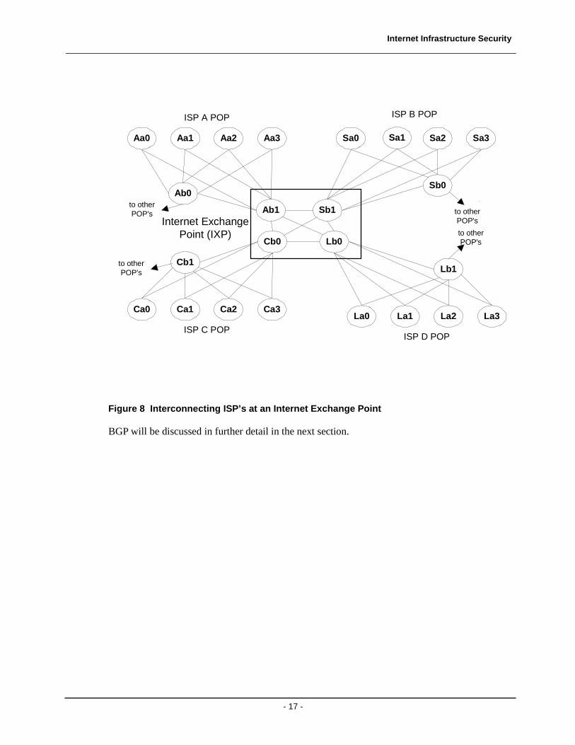
Figure 8 presents a conceptual view of four ISP’s peering with each other at an Internet Exchange Point. In this example, each ISP is assumed to have a peering relationship with each other. The actual interconnection between the ISP’s is typically done through layer 2 services such as Frame Relay or ATM. The Border Gateway Protocol (BGP-4) is used by the ISP’s to advertise IP routes to one another.
Internet Infrastructure Security
- 17 -
Ab0
Aa0 Aa1 Aa2 Aa3
Ab1
ISP A POP
Sb1
Sa0 Sa1 Sa2 Sa3
Sb0
ISP B POP
Cb1
Ca0 Ca1 Ca2 Ca3
Cb0
ISP C POP
Lb0
La0 La1 La2 La3
Lb1
ISP D POP
to otherPOP's
to otherPOP's
to otherPOP's
to otherPOP's
Internet ExchangePoint (IXP)
Figure 8 Interconnecting ISP’s at an Internet Exchange Point
BGP will be discussed in further detail in the next section.
Internet Infrastructure Security
- 18 -
4 Internet Routing
Section 3 presented a brief introduction into how a “network of networks” is connected. The following section discusses how packets are actually routed amongst those networks.
Given that the Internet is a “network of networks”, it should also come as no surprise that no single authority manages all these individual networks. In other words, each network is autonomous. An Autonomous System (AS) is a network managed by a single authority. The same management authority may operate more than one network (AS). Since different management authorities will manage different networks, it should also be easy to see that these different networks may use different protocols internally to route packets from one source to another. For instance, ISP “A” may use IS-IS as its internal routing protocol, while ISP “B” may use OSPF. Yet, for these networks, to be able to exchange routing information with each other, a common routing protocol must be used.
Therefore, the Internet has evolved to support two different routing mechanisms:
1. Intra-AS routing: Routing within an AS (or domain)
2. Inter-AS routing: Routing between different AS’s
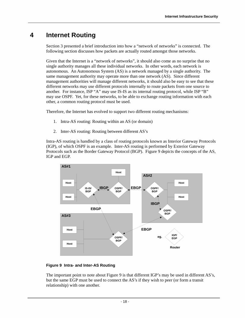
Intra-AS routing is handled by a class of routing protocols known as Interior Gateway Protocols (IGP), of which OSPF is an example. Inter-AS routing is performed by Exterior Gateway Protocols such as the Border Gateway Protocol (BGP). Figure 9 depicts the concepts of the AS, IGP and EGP.
Host
IS-IS/BGP
Host
Host
Host
Host
Host
EBGP
EBGP
EBGP
AS#1
AS#3
AS#2
OSPF/BGP
OSPF/BGP
OSPF/BGP
OSPF/BGP
Host
IBGP
IBGP
IGP/EGP
Router
eg.
Figure 9 Intra- and Inter-AS Routing
The important point to note about Figure 9 is that different IGP’s may be used in different AS’s, but the same EGP must be used to connect the AS’s if they wish to peer (or form a transit relationship) with one another.
Internet Infrastructure Security
- 19 -
4.1 Open Shorted Path First (OSPF)
OSPF, defined in RFC 2328, is a link state routing protocol [1]. As with all link state protocols, OSPF-enabled routers exchange link state advertisements with one another to build a shortest path tree using Dijkstra’s algorithm. OSPF offers the following features:
• Load balancing
• Multiple metrics
• Network partitioning through creation of areas
• Authentication of router exchanges
One of the key benefits of OSPF is the ability to partition a network into different areas. This allows route summarization, which offers several benefits, including [1]:
• link state flooding is limited to the area in which the router is located
• reduced size of the link state database maintained by each router
• reduced computation time for the shortest path tree
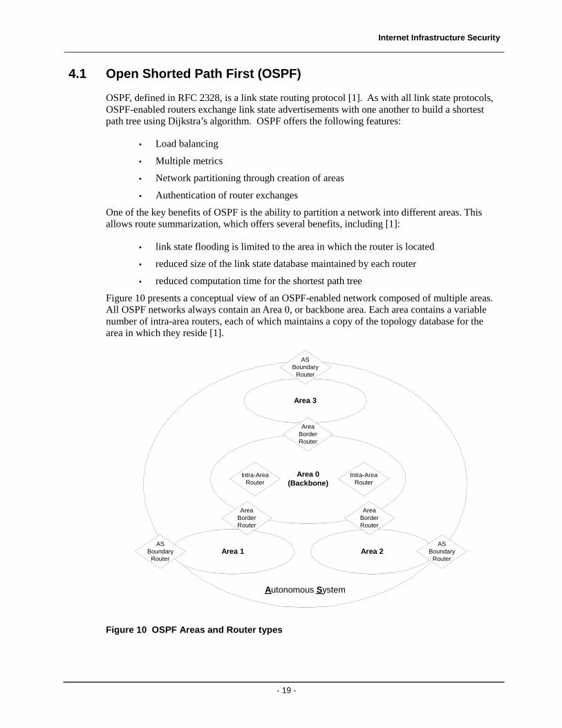
Figure 10 presents a conceptual view of an OSPF-enabled network composed of multiple areas. All OSPF networks always contain an Area 0, or backbone area. Each area contains a variable number of intra-area routers, each of which maintains a copy of the topology database for the area in which they reside [1].
text
Area 0(Backbone)
Intra-AreaRouter
Intra-AreaRouter
Area 2
AreaBorderRouter
Area 1
AreaBorderRouter
Area 3
AreaBorderRouter
ASBoundary
Router
ASBoundary
Router
ASBoundary
Router
Autonomous System
Figure 10 OSPF Areas and Router types
Internet Infrastructure Security
- 20 -
The backbone area physically connects to all other areas of the network via Area Border Routers. The Area Border Routers maintain separate topology databases for each area it straddles. The ABR advertises the routes from one of the areas in which it straddles to the other areas. For instance, in Figure 10, the Area Border Router in area 1 announces area 1’s routes into area 0, and vice versa. This function is known as route summarization [1].
Finally, the AS Boundary Router (ASBR) interfaces with other external autonomous systems using an exterior gateway protocol such as BGP. The ASBR advertises routes learned through the EGP process into the AS. Similarly, the ASBR provides reachability information about its own AS to the external world.
4.1.1 OSPF Operation
There are four main phases of OSPF operation:
1. Neighbor discovery
2. Link State Advertisement generation
3. Link State Advertisement propagation
4. Shortest path calculation
In the first phase, OSPF-enabled routers transmit HELLO packets on all its interfaces. The HELLO packet contains a list of other routers for which this router has received a HELLO packet. When a router receives a HELLO packet that contains its own router ID, a neighbor relationship is established. Only after the neighbor’s topology databases are synchronized, are they considered adjacent.
In the second phase, OSPF-enabled routers generate Link State Advertisements when they acquire new neighbors, or when a link cost changes. These LSA’s contain a list of neighbor routers, the link costs, and a sequence number that allows the receiving router to know which is the most recently generated LSA.
Next, these LSA’s are flooded throughout the area to ensure that each router knows the topology, and can complete its shortest path calculation. Each LSA is acknowledged to ensure reliability.
Finally, Dijkstra’s algorithm is used to create a shortest path tree.
4.1.2 OSPF Packet Types
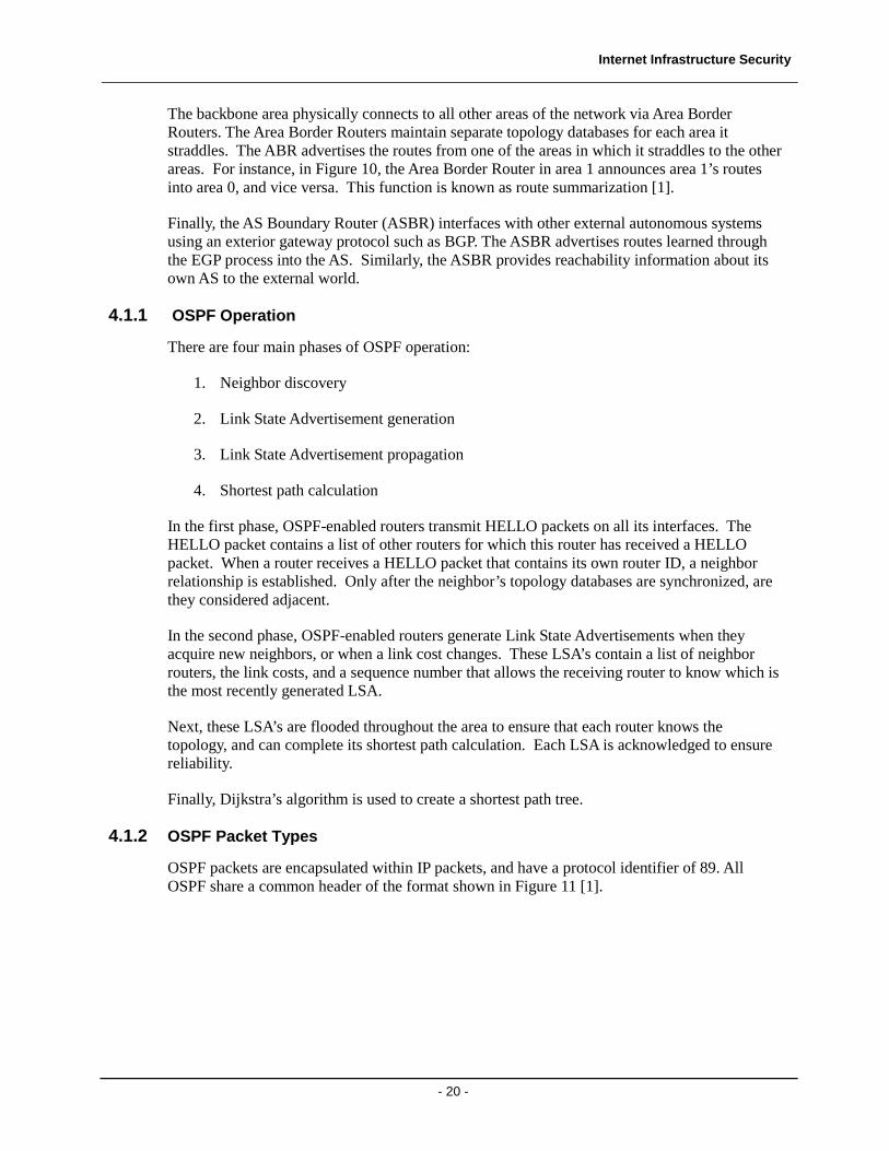
OSPF packets are encapsulated within IP packets, and have a protocol identifier of 89. All OSPF share a common header of the format shown in Figure 11 [1].
Internet Infrastructure Security
- 21 -
Version
Packet Type
Packet Length
Router ID
Area ID
Checksum
Authentication Type
Authentication Data
Octets1
1
2
4
4
2
2
8
Figure 11 OSPF Header
The packet type field indicates one of five possible OSPF packet types:
Hello – Type 1
Hello packets are used to discover and maintain neighbor relationships
Database Description – Type 2
Database description packets are used to convey a routers link state database to another router when the two routers are attempting to establish a neighbor adjacency. The exchange of link state database occurs in both directions.
Link State Request – Type 3
Link state request packets are exchanged when a router determines that the data received via a Database Description exchange is out of date. The router uses this packet type to request more up to date information.
Link State Update – Type 4
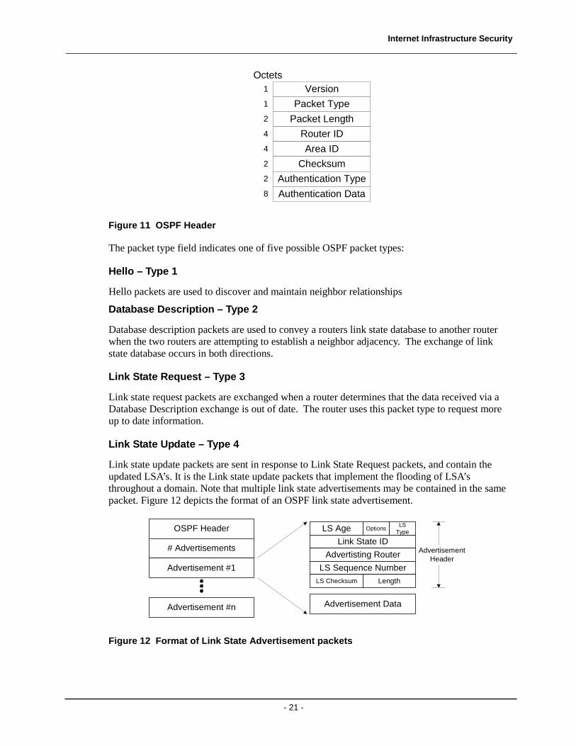
Link state update packets are sent in response to Link State Request packets, and contain the updated LSA’s. It is the Link state update packets that implement the flooding of LSA’s throughout a domain. Note that multiple link state advertisements may be contained in the same packet. Figure 12 depicts the format of an OSPF link state advertisement.
OSPF Header
# Advertisements
Advertisement #1
Advertisement #n
LS Age Options
Link State ID
LSType
Advertisting Router
LS Sequence NumberLS Checksum Length
Advertisement Data
AdvertisementHeader
Figure 12 Format of Link State Advertisement packets
Internet Infrastructure Security
- 22 -
Link State Acknowledgment – Type 5
Link state acknowledgement packets are sent in acknowledgement of a successfully received link state advertisement.
4.1.3 The OSPF Packet Authentication Field
Another field of interest in the OSPF packet header (see Figure 11) is the authentication fields. The Authentication Type field indicates the type of authentication used (if any). There are three possible options [1]:
Null Authentication
No authentication is performed.
Simple Password
A simple 64-bit password is shared by all routers in the area, and inserted into each OSPF packet generated by every router in the area.
Cryptographic Authentication
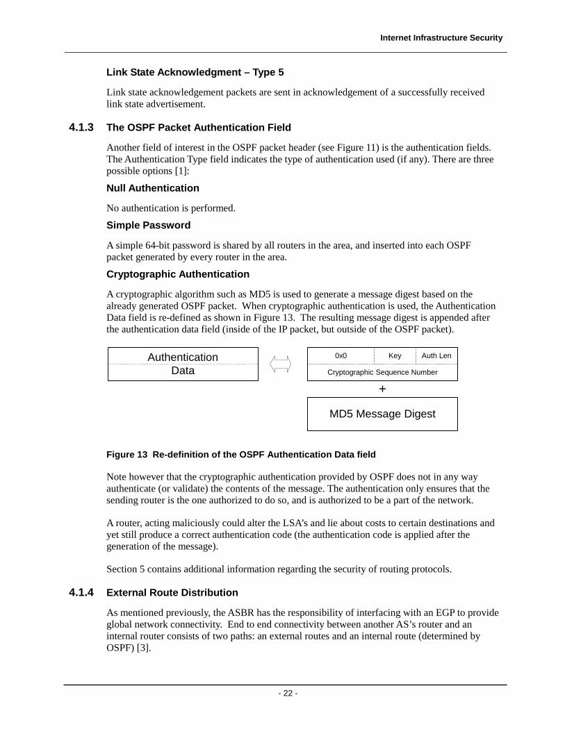
A cryptographic algorithm such as MD5 is used to generate a message digest based on the already generated OSPF packet. When cryptographic authentication is used, the Authentication Data field is re-defined as shown in Figure 13. The resulting message digest is appended after the authentication data field (inside of the IP packet, but outside of the OSPF packet).
AuthenticationData
0x0 Key Auth Len
Cryptographic Sequence Number
MD5 Message Digest
+
Figure 13 Re-definition of the OSPF Authentication Data field
Note however that the cryptographic authentication provided by OSPF does not in any way authenticate (or validate) the contents of the message. The authentication only ensures that the sending router is the one authorized to do so, and is authorized to be a part of the network.
A router, acting maliciously could alter the LSA’s and lie about costs to certain destinations and yet still produce a correct authentication code (the authentication code is applied after the generation of the message).
Section 5 contains additional information regarding the security of routing protocols.
4.1.4 External Route Distribution
As mentioned previously, the ASBR has the responsibility of interfacing with an EGP to provide global network connectivity. End to end connectivity between another AS’s router and an internal router consists of two paths: an external routes and an internal route (determined by OSPF) [3].
Internet Infrastructure Security
- 23 -
When the ASBR advertises the external route, it may advertise the cost as the sum of the external (i.e. BGP) and internal (OSPF) costs, or as the external cost only. The choice is configuration dependent. The importance of such a choice becomes apparent if more than one internal router, with different link costs to the ASBR, receives the external advertisement.
4.2 Border Gateway Protocol (BGP)
The Border Gateway Protocol [2], BGP, is the most common exterior gateway protocol. It is used extensively to exchange routing information between Autonomous Systems. Unlike OSPF, BGP is a path vector algorithm in which the route to a network is specified by a list of AS identifiers. There is no metric associated with these paths because each AS can use its own criteria for determining the preference of a specific route (in other words, there is no way to provide universally agreed upon metrics). Therefore BGP routing is largely based upon route preferences (use or don’t use a specific AS) and routing policy.
Also unlike OSPF, a BGP speaker (a router running the BGP protocol) does not know the full topology of the network. BGP peers form TCP connections over which they exchange routing information amongst themselves.
Note that BGP peers can be classified as one of two types:
• Internal BGP (IBGP): Peers within the same AS
• External BGP (EBGP): Peers in different AS’s
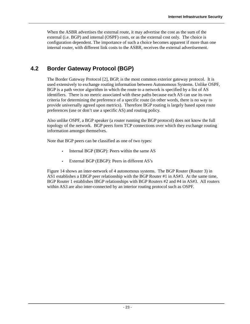
Figure 14 shows an inter-network of 4 autonomous systems. The BGP Router (Router 3) in AS1 establishes a EBGP peer relationship with the BGP Router #1 in AS#3. At the same time, BGP Router 1 establishes IBGP relationships with BGP Routers #2 and #4 in AS#3. All routers within AS3 are also inter-connected by an interior routing protocol such as OSPF.
Internet Infrastructure Security
- 24 -
AS3
AS1
AS4AS2
IGP Internetwork
BGPRouter 1
BGPRouter 2
BGPRouter 3
BGPRouter 4
BGPRouter 5 BGP
Router 6
IBGP
IBGP IBGP
EBGP
EB
GPE
BG
P
Figure 14 BGP Internetwork
IBGP allows routes learned by one BGP router in an AS to be propagated to other BGP routers without relying on IGP protocols such as OSPF.
Provided that the routing policy allows it, and the correct peering relationship exists, EBGP peers advertise routes to one another. However routes learned through IBGP connections are only advertised externally, and not to other IBGP peers. This is because BGP requires that BGP routers within the same AS be connected by a full mesh of IBGP connections [2].
BGP and interior routing protocols must co-operate to ensure full connectivity. In a typical ISP’s routing table, BGP would maintain the customer routes, while the IGP (such as OSPF) would maintain the internal topology of the ISP’s network [3]
For instance, a packet may need to be routed from one BGP router (i.e. BGP Router 4 in Figure 14) to another BGP router in the same AS (i.e. BGP Router 2 in Figure 14). The BGP advertisement received by BGP Router 4 contains a next hop address that points to BGP Router 2, however, BGP does not know how to get the packet from Router 4 to Router 2. Therefore, Router 4 will use the next hop address to look inside the OSPF area of the routing database to determine the way to get to Router 2 [3].
4.2.1 BGP Operation
There are three main phases of BGP operation:
1. Opening a BGP connection
2. Exchange of Routing tables
Internet Infrastructure Security
- 25 -
3. Maintenance of the BGP connections.
As mentioned previously, BGP peers open TCP connections with one another using port 179. Once the TCP connection is established, the peers send BGP OPEN messages to one another, which must be acknowledged by a BGP KEEPALIVE message.
Once the BGP peers have opened a connection, they exchange routing tables via BGP UPDATE messages. Once the complete routing table has been forwarded, only incremental updates are sent via UPDATE messages.
BGP routers (other than those at the edge of the Internet) maintain complete routing tables, allowing traffic to be routed to any reachable destination. BGP update messages are forwarded to all neighbors, and indicate a particular routers “best” (or more accurately, preferred) route to each destination.
When a BGP router forwards an UPDATE message to its neighbors, it prepends its AS number to the AS path sequence.
Finally, BGP peers maintain their connection through the periodic exchange of BGP KEEPALIVE packets. If a BGP packet is not received for a certain of time, the connection is closed.
4.2.2 BGP Packet Formats
BGP packets are encapsulated within TCP segments, and use TCP port 179.
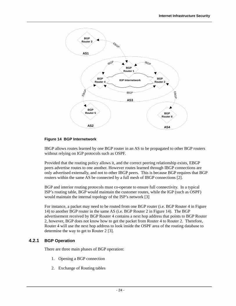
All BGP packets begin with the common header depicted in Figure 15. The marker field is essentially an authentication field that is commonly set to all 1’s, but may be used for providing cryptographic authentication.
The Length field specifies the length of the BGP message (including header).
The type field indicates one of the following possible BGP message types:
1. OPEN
2. UPDATE
3. NOTIFICATION
4. KEEPALIVE
Marker
Length
Type
Octets16
2
1
Figure 15 BGP Common Header
Internet Infrastructure Security
- 26 -
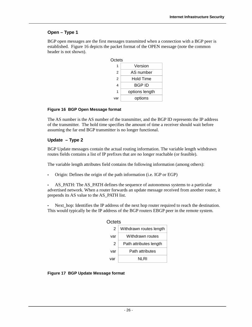
Open – Type 1
BGP open messages are the first messages transmitted when a connection with a BGP peer is established. Figure 16 depicts the packet format of the OPEN message (note the common header is not shown).
Version
AS number
Hold Time
BGP ID
options length
options
Octets1
2
2
4
1
var
Figure 16 BGP Open Message format
The AS number is the AS number of the transmitter, and the BGP ID represents the IP address of the transmitter. The hold time specifies the amount of time a receiver should wait before assuming the far end BGP transmitter is no longer functional.
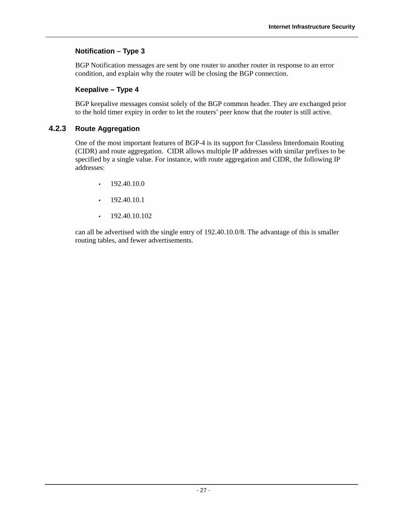
Update – Type 2
BGP Update messages contain the actual routing information. The variable length withdrawn routes fields contains a list of IP prefixes that are no longer reachable (or feasible).
The variable length attributes field contains the following information (among others):
• Origin: Defines the origin of the path information (i.e. IGP or EGP)
• AS_PATH: The AS_PATH defines the sequence of autonomous systems to a particular advertised network. When a router forwards an update message received from another router, it prepends its AS value to the AS_PATH list.
• Next_hop: Identifies the IP address of the next hop router required to reach the destination. This would typically be the IP address of the BGP routers EBGP peer in the remote system.
Withdrawn routes length
Withdrawn routes
Path attributes length
Path attributes
NLRI
Octets2
2
var
var
var
Figure 17 BGP Update Message format
Internet Infrastructure Security
- 27 -
Notification – Type 3
BGP Notification messages are sent by one router to another router in response to an error condition, and explain why the router will be closing the BGP connection.
Keepalive – Type 4
BGP keepalive messages consist solely of the BGP common header. They are exchanged prior to the hold timer expiry in order to let the routers’ peer know that the router is still active.
4.2.3 Route Aggregation
One of the most important features of BGP-4 is its support for Classless Interdomain Routing (CIDR) and route aggregation. CIDR allows multiple IP addresses with similar prefixes to be specified by a single value. For instance, with route aggregation and CIDR, the following IP addresses:
• 192.40.10.0
• 192.40.10.1
• 192.40.10.102
can all be advertised with the single entry of 192.40.10.0/8. The advantage of this is smaller routing tables, and fewer advertisements.
Internet Infrastructure Security
- 28 -
5 Internet Infrastructure Security
Internet and network security can be considered to have two components:
• Data security
• Infrastructure security
Extensive research and development efforts have been expended to secure the user data that traverses a network. IPSec (IP Security) is a standards-based approach that utilizes encryption and authentication algorithms to provide the following services:
• Data confidentiality: Data is encrypted using algorithms such as DES, 3DES, or AES to protect the contents of the message
• Data Integrity: Data is authenticated to enable to the receiver to be assured it has not be altered in transit
• Data origin authentication: The source of the sending packet can be authenticated in a way similar to that used for data integrity
• Ant-replay: IPSec packets contain sequence numbers that can help prevent replay attacks
However, largely due to the scope of the problem, little concrete advancement has been made in securing the actual infrastructure itself, and the routing protocols it is built on. Section 4.1.3 described the use of the authentication field in OSPF packets. But, even if using strong cryptographic authentication procedures, only the identity of the router sending the OSPF packet is authenticated. It does not guarantee that the contents of the advertisement are indeed accurate.
5.1 Internet Infrastructure Weaknesses
Chakrabarti and Manimaran [8] describe four general categories of attacks against the network infrastructure:
1. DNS Hacking
2. Packet Mistreatment
3. Denial of Service
4. Routing Table Poisoning
The end goal of all of these attacks is to either intercept, corrupt, analyze, or even outright drop the traffic.
The following sections describe each of the aforementioned categories.
Internet Infrastructure Security
- 29 -
5.1.1 DNS Hacking
The DNS is a server-based, hierarchically organized global directory that translates host names into IP addresses. Information linking a host name with a particular IP address is stored locally on each server in a cache. If one particular DNS server cannot perform the host name to IP address conversion, it consults the next closest DNS server to the root (if one considers the DNS system as a tree).
An attacker who can gain access to the DNS cache of a particular server can cause a wide variety of problems as listed in [8], including:
• Denial of Service: The server can be made to return negative responses, or return the IP address of an unintended host (including one under the control of an attacker)
• Masquerading: The server can be made to return the IP address of the attacker, which could allow the attacker to masquerade as the trusted host.
The IETF has proposed DNSSEC [12] as a means to provide a more secure DNS system. However, any potential adoption of DNSSEC is likely to be slow due to the ubiquity of the currently deployed system.
5.1.2 Packet Mistreatment
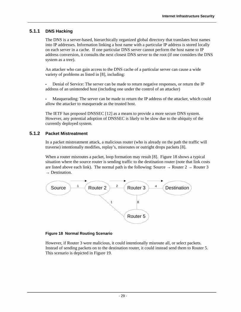
In a packet mistreatment attack, a malicious router (who is already on the path the traffic will traverse) intentionally modifies, replay’s, misroutes or outright drops packets [8].
When a router misroutes a packet, loop formation may result [8]. Figure 18 shows a typical situation where the source router is sending traffic to the destination router (note that link costs are listed above each link). The normal path is the following: Source → Router 2 → Router 3 → Destination.
Source Router 2 Router 3
Router 5
Destination1 2 4
81
Figure 18 Normal Routing Scenario
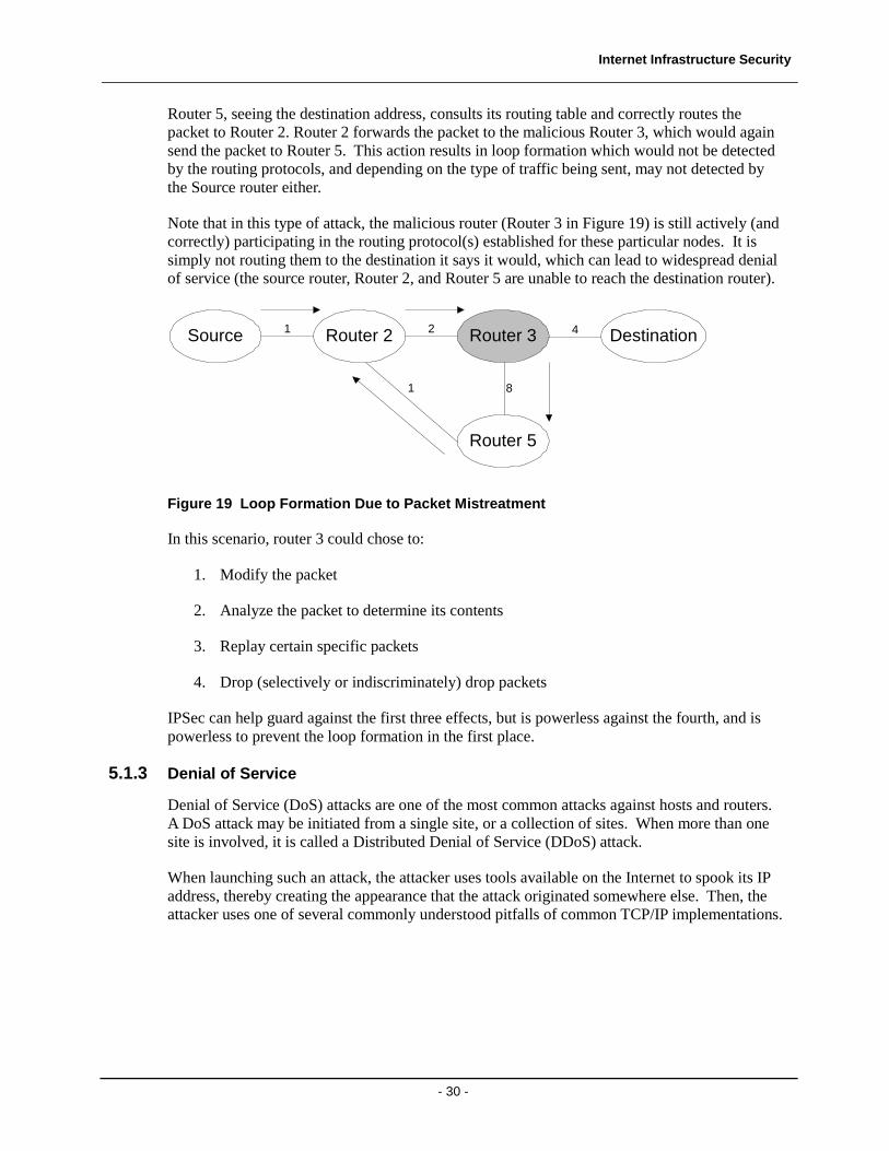
However, if Router 3 were malicious, it could intentionally misroute all, or select packets. Instead of sending packets on to the destination router, it could instead send them to Router 5. This scenario is depicted in Figure 19.
Internet Infrastructure Security
- 30 -
Router 5, seeing the destination address, consults its routing table and correctly routes the packet to Router 2. Router 2 forwards the packet to the malicious Router 3, which would again send the packet to Router 5. This action results in loop formation which would not be detected by the routing protocols, and depending on the type of traffic being sent, may not detected by the Source router either.
Note that in this type of attack, the malicious router (Router 3 in Figure 19) is still actively (and correctly) participating in the routing protocol(s) established for these particular nodes. It is simply not routing them to the destination it says it would, which can lead to widespread denial of service (the source router, Router 2, and Router 5 are unable to reach the destination router).
Source Router 2 Router 3
Router 5
Destination1 2 4
81
Figure 19 Loop Formation Due to Packet Mistreatment
In this scenario, router 3 could chose to:
1. Modify the packet
2. Analyze the packet to determine its contents
3. Replay certain specific packets
4. Drop (selectively or indiscriminately) drop packets
IPSec can help guard against the first three effects, but is powerless against the fourth, and is powerless to prevent the loop formation in the first place.
5.1.3 Denial of Service
Denial of Service (DoS) attacks are one of the most common attacks against hosts and routers. A DoS attack may be initiated from a single site, or a collection of sites. When more than one site is involved, it is called a Distributed Denial of Service (DDoS) attack.
When launching such an attack, the attacker uses tools available on the Internet to spook its IP address, thereby creating the appearance that the attack originated somewhere else. Then, the attacker uses one of several commonly understood pitfalls of common TCP/IP implementations.
Internet Infrastructure Security
- 31 -
As an example, in a TCP SYN flood attack, the attacker overwhelms the target with a large number of TCP SYN segments. The target begins transmitting (and queuing) SYN-ACKS to the spooked return address (in accordance with step 2 of the TCP 3-way handshake). However, since it never receives ACK’s from the spoofed address (which would complete the 3-way handshake), eventually the targets queues overflow, and the target spends its time waiting for ACK’s which it will never receive.
Another way to cause of Denial of Service is to overwhelm a router or cause congestion on a link.
5.1.4 Routing Table Poisoning
The collective routing tables of all the routers in a network can be considered the glue that holds the Internet together [8]. The routing tables are built by the routing protocols (such as OSPF and BGP-4) that were discussed earlier in this document.
There are two main types of routing table poisoning attacks, link and router. Both share the same goal of causing the routing tables to contain false information.
Note that all routing protocols, including OSPF, RIP, and BGP-4 are vulnerable to the following attacks, although OSPF is used for the examples that follow.
Link Attacks
Link attacks are characterized by the modification, replication, or interruption of routing protocol updates and occur when the attacker has control of, or access to the physical link.
The authentication fields contained in OSPF packet can help mitigate (but not eliminate) the effects of modification and replication attacks. The redundant nature of the Internet can provide some protection against interruption of routing updates, since generally there can be more than one path between source and destination. That said, the periodic interruption of routing table updates can lead to routing flaps, and the potential for routing tables to not be synchronized (or converged).
Router Attacks
Routers share what can be considered an implicit trust relationship with one another. That is, what one router says, all other routers that receive that message believe. The problem is, that a router can lie or act maliciously, which is the hallmark of the router attack.
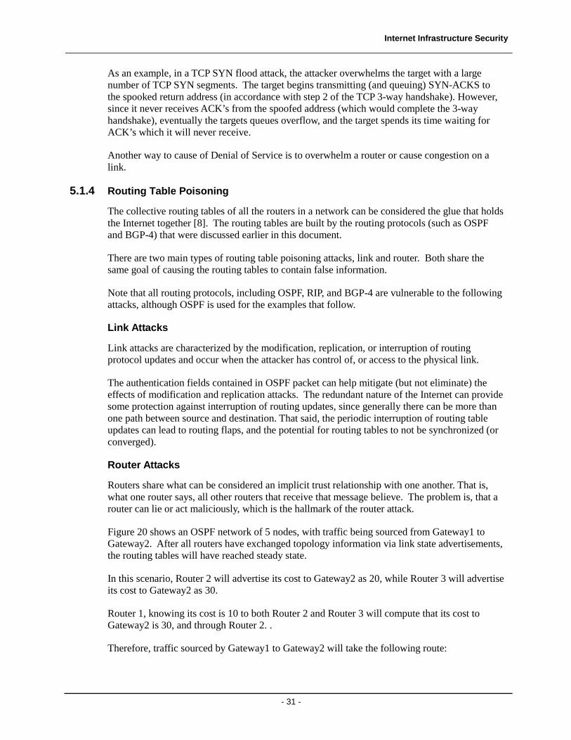
Figure 20 shows an OSPF network of 5 nodes, with traffic being sourced from Gateway1 to Gateway2. After all routers have exchanged topology information via link state advertisements, the routing tables will have reached steady state.
In this scenario, Router 2 will advertise its cost to Gateway2 as 20, while Router 3 will advertise its cost to Gateway2 as 30.
Router 1, knowing its cost is 10 to both Router 2 and Router 3 will compute that its cost to Gateway2 is 30, and through Router 2. .
Therefore, traffic sourced by Gateway1 to Gateway2 will take the following route:
Internet Infrastructure Security
- 32 -
Gateway1 → Router 1 → Router 2 → Gateway2
as this path has the least cost (50).
Gateway1 Gateway2
Router 1 Router 2
Router 3
1010
10
2020
Figure 20 OSPF Network: Normal Scenario
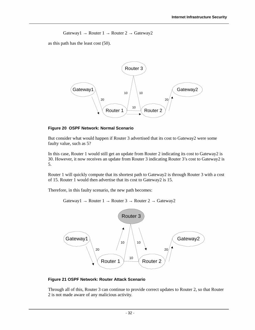
But consider what would happen if Router 3 advertised that its cost to Gateway2 were some faulty value, such as 5?
In this case, Router 1 would still get an update from Router 2 indicating its cost to Gateway2 is 30. However, it now receives an update from Router 3 indicating Router 3’s cost to Gateway2 is 5.
Router 1 will quickly compute that its shortest path to Gateway2 is through Router 3 with a cost of 15. Router 1 would then advertise that its cost to Gateway2 is 15.
Therefore, in this faulty scenario, the new path becomes:
Gateway1 → Router 1 → Router 3 → Router 2 → Gateway2
Gateway1 Gateway2
Router 1 Router 2
Router 3
1010
10
2020
Figure 21 OSPF Network: Router Attack Scenario
Through all of this, Router 3 can continue to provide correct updates to Router 2, so that Router 2 is not made aware of any malicious activity.
Internet Infrastructure Security
- 33 -
Once this attack is accomplished, Router 3 is free to do whatever it likes with the traffic flowing between Gateway1 and Gateway2, including drop, modify, analyze or even replay it.
5.2 Internet Infrastructure Security Solutions
As mentioned previously, DNSSEC [12] is a proposed method to reduce the effects of DNS hacking attacks. At the same time, security suites such as IPSec can be used to guard against packet snooping and modification, while also providing data origin authentication. In addition, careful router configuration such as the use of access control lists, and vigilance by router vendors (by providing software upgrades to known security holes) can help guard against Denial of Service attacks.
However, securing the actual routing protocols is still largely an unresolved problem for many reasons including:
• It is a difficult problem to solve due to the implicit trust relationships
• Security was not necessarily built into the routing protocols at the beginning, and therefore is not easy to add in
• Adding additional security to the routing protocols requires adoption by many competing interests including:
o Vendors
o ISP’s
• The entire installed base of routing protocol enabled equipment would likely need to be upgraded and or replaced
That said, one example of a secure routing protocol proposal is Secure-BGP (S-BGP). The following section briefly describes the main modifications S-BGP proposes.
5.2.1 Secure-BGP (S-BGP)
Secure-BGP, discussed in detail in [4, 5, 6], consists of the following four major components:
1. A Public Key Infrastructure (PKI) and associated digital certificates
2. Attestations
3. IPSec is used to secure and authenticate the communications between each BGP peer (both IBGP and EBGP).
4. Update validation
The following describes each of these components in further detail.
Internet Infrastructure Security
- 34 -
Public Key Infrastructure (PKI)
S-BGP uses 2 PKI systems based on X.509 digital certificates. The first PKI system is specific to IP address allocation and binds blocks of IP addresses to a specific organization. The digital certificates in this PKI are intended to prove ownership of a block of addresses.
The second PKI is used to validate the assignment of AS numbers and BGP speakers, and the relationship between AS’s and BGP speakers.
In total, S-BGP calls for four digital certificates:
1. One certificate is granted to each organization to verify ownership over a block (or multiple blocks) of IP addresses.
2. A second certificate to associate an AS number with an organizations public key. This certificate is issued by an Internet registry (and signed using the registry’s private key).
3. A third certificate, similar to the second, associates an AS number with an organizations public key. The difference is that this certificate is issued by the organization itself (and signed using the private key that corresponds to the public key used for the second certificate above).
4. A fourth certificate binds a routers ID, name, AS number, and the router’s public key. This certificate is issued by an organization (and signed using the private key that corresponds to the public key used for the second certificate above).
Attestations
An attestation is a digitally signed piece of data that verifies that an AS is authorized by the signer (an ISP) to advertise a path to specified prefixes. There are two types of attestations, address and route, which share a common format:
• Address Attestations (AA): Signed by an ISP or subscriber that controls the prefixes in the AA, and the target is a set of ASes that the ISP/subscriber authorizes to originate a route to the prefixes. An address attestation is essentially static, as IP address assignment rarely changes
• Route Attestation (RA): Signed by an S-BGP router (operating on behalf of an ISP), with the target being an AS or set of ASes, representing the neighbors to which the UPDATE containing the RA will be sent. A route attestation can change much more frequently than address attestations due to the very nature of dynamic routing protocols.
IPSec
As mentioned in section 4.2.2 BGP uses TCP to established connections between IBGP and EBGP peers. S-BGP [4, 5] proposes that the IPSec ESP [13] protocol in transport mode with null encryption be used to provide:
• Authentication
• Data integrity
Internet Infrastructure Security
- 35 -
• Anti-replay protection
between peers. Use of these measures will prevent many of the link attacks described in the previous section.
Update Validation
Together, the digital certificates and attestations are used to verify the routing information sent in BGP UPDATE messages. The routing information advertising a route from AS#1 to AS#N requires:
• One address attestation for each address block contained UPDATE
• One address certificate for each address block contained UPDATE
• One route attestation for every AS along the path from AS#1 to AS#N
• One certificate for each AS along the path from AS#1 to AS#N so that the digital signatures may be verified
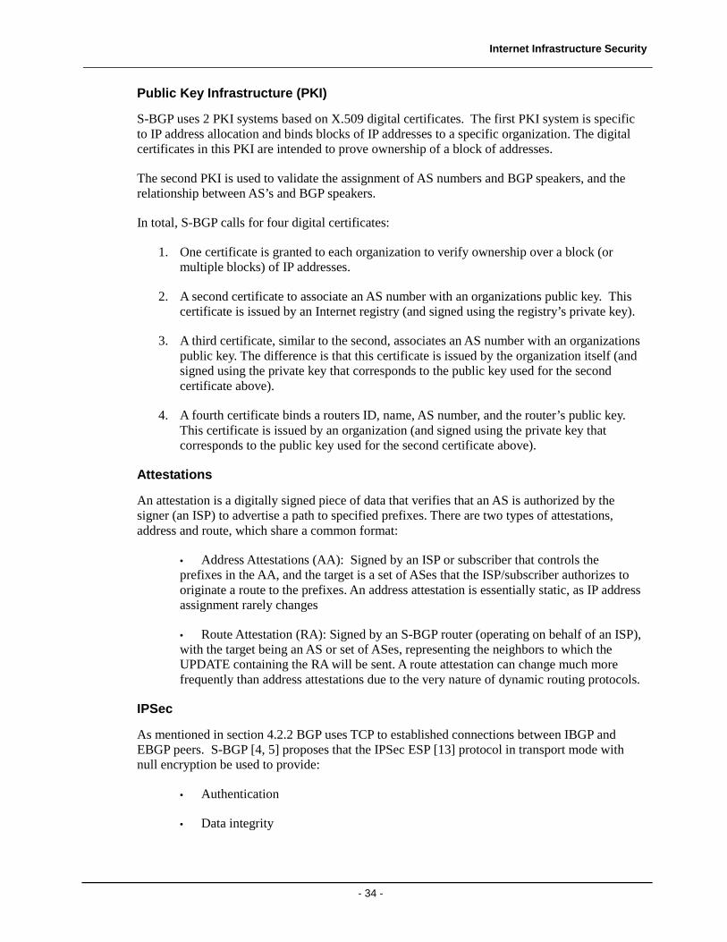
The path attributes section of the BGP UPDATE message is modified as below to accomplish this new functionality for S-BGP:
Path attributesAttribute Header
Route Attestations
Attestation header
Issuer
Certificate IDAlgorithm ID/
Signature
Signed Info
Validity Dates
Subject
AS Path Info
Other path attributes
NLRI Info
Figure 22 Redefinition of the BGP Update message
Note that there would be one set of the above information for each route advertised in the S-BGP Update message.
Internet Infrastructure Security
- 36 -
5.3 Link Cutting Attacks
Although exterior routing protocols such as BGP advertise preferred routes to destinations, typically many different routes exist between a source and a destination. Therefore, a link cutting attack that reduces the “degree of preference” of a specific route can still force traffic to follow a desired path, ostensibly to allow an attacker access to the traffic. Routing protocols such as S-BGP that offer a high degree of protection against vulnerabilities such as false advertisements, are still open to link cutting attacks.
A link cutting attack essentially ‘cuts’ links to cause traffic to be re-routed through a router or link controlled by an adversary. The link cut may be physical, such as the severing of a fiber optic cable, or logical, such as that caused by a Denial of Service [9].
To employ a link cutting attack, one needs information about the networks topology. This paper has already discussed typical network architectures and ISP POP designs. In addition, researchers at the University of Washington have shown that highly accurate network maps can be drawn using traceroute servers [10]
A simple traceroute launched from this computer to www.sprint.net (199.0.233.22) yielded the following information:
1 20 ms 30 ms 20 ms 209.53.1.226 2 20 ms 30 ms 20 ms 208.181.229.118 3 20 ms 30 ms 20 ms vancbc01gr01.bb.telus.com [154.11.4.97] 4 30 ms 30 ms 30 ms vancbc01br01.bb.telus.com [154.11.10.49] 5 20 ms 30 ms 30 ms sttlwa01gr01.bb.telus.com [209.53.75.166] 6 20 ms 30 ms 30 ms sl-gw14-sea-10-0.sprintlink.net [144.224.23.33] 7 20 ms 30 ms 30 ms sl-bb21-sea-9-1.sprintlink.net [144.232.6.133] 8 70 ms 70 ms 70 ms sl-bb25-chi-2-0.sprintlink.net [144.232.20.157] 9 70 ms 71 ms 70 ms sl-bb23-chi-15-0.sprintlink.net [144.232.26.93] 10 90 ms 90 ms 90 ms sl-bb27-rly-11-0.sprintlink.net [144.232.20.185] …
This simple traceroute shows that a Telus backbone router (209.53.75.166) peers with a Sprint gateway router in Seattle (144.224.23.33).
5.3.1 Link Cutting Example
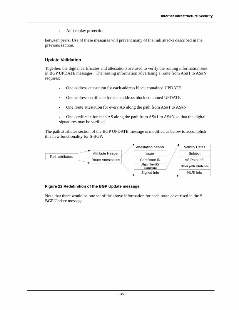
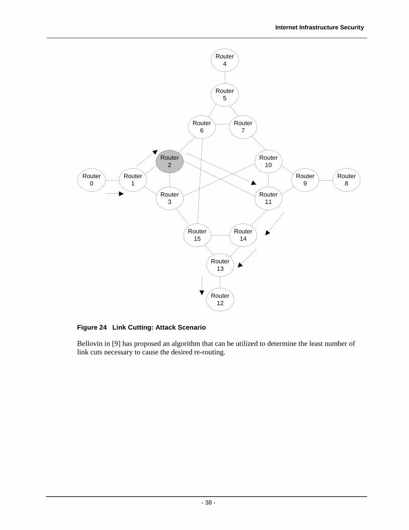
As an example, consider the network topology shown in Figure 23. In this example, router 0 is the source of the traffic, and router 12 is the destination. Under normal routing conditions, the traffic would flow traverse the following path:
Router 0 → Router 1 → Router 3 → Router 15 → Router 13 → Router 12
Internet Infrastructure Security
- 37 -
Router1
Router2
Router3
Router0
Router9
Router10
Router11
Router8
Router15
Router14
Router13
Router12
Router6
Router5
Router7
Router4
Figure 23 Link Cutting: Normal Scenario
However, consider what would happen if an adversary were in control of Router 2, and link cutting was used to sever all BGP links of router 3 (i.e. links 2 → 3, 3 → 15, and 3 → 10).
Under this attack scenario, traffic would be forced to traverse Router 2, allowing the adversary to do any of the packet mistreatment attacks discussed earlier in section 5.1.2.
The new traffic routing will appear as in Figure 24
Internet Infrastructure Security
- 38 -
Router1
Router2
Router3
Router0
Router9
Router10
Router11
Router8
Router15
Router14
Router13
Router12
Router6
Router5
Router7
Router4
Figure 24 Link Cutting: Attack Scenario
Bellovin in [9] has proposed an algorithm that can be utilized to determine the least number of link cuts necessary to cause the desired re-routing.
Internet Infrastructure Security
- 39 -
6 Experimental Results
This section will provide a demonstration (along with the results obtained) of two of the attacks described in this document:
1. Routing Table Poisoning in an OSPF environment.
2. Link Cutting in an inter-domain routing environment.
6.1 Route Table Poisoning Demonstration
OPNET was used to create 2 different topologies. The first topology is used to show the affects of such an attack on the routing tables, while the second topology shows more global effects of such an attack.
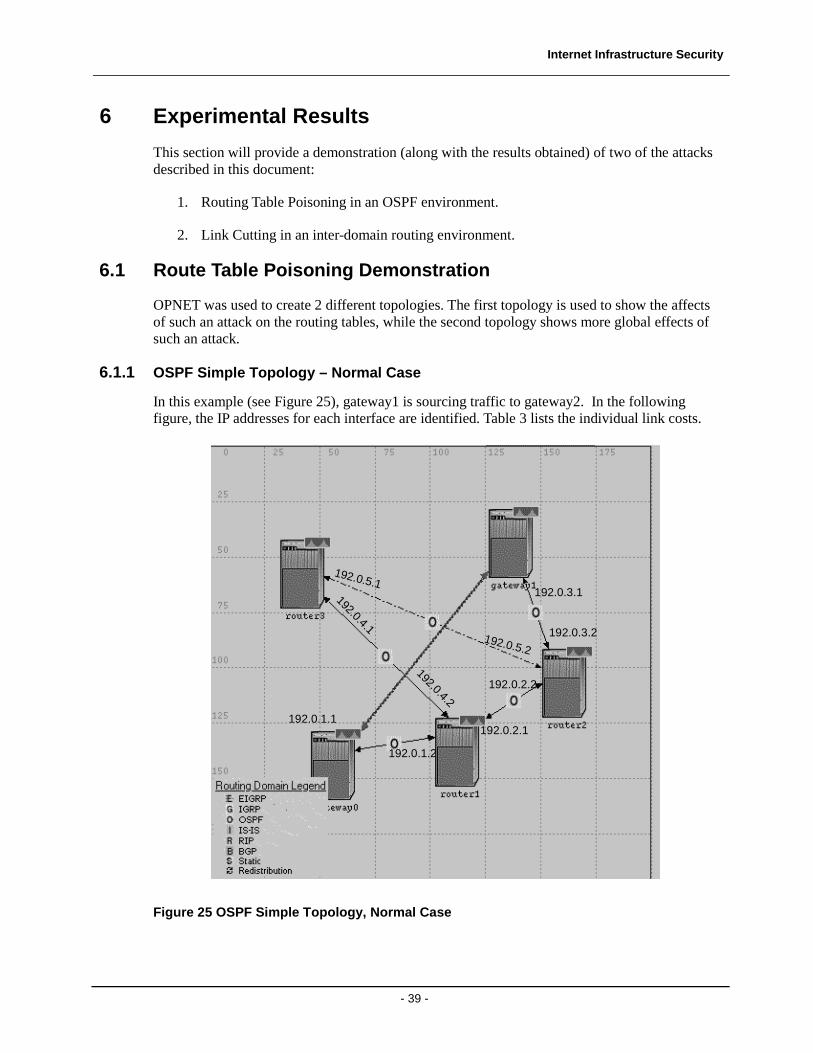
6.1.1 OSPF Simple Topology – Normal Case
In this example (see Figure 25), gateway1 is sourcing traffic to gateway2. In the following figure, the IP addresses for each interface are identified. Table 3 lists the individual link costs.
192.0.1.1
192.0.1.2
192.0.4.2
192.0.2.1
192.0.2.2
192.0.4.1
192.0.5.1
192.0.5.2
192.0.3.2
192.0.3.1
Figure 25 OSPF Simple Topology, Normal Case
Internet Infrastructure Security
- 40 -
Table 3 OSPF Simple Topology, Link Costs
SOURCE ROUTER, INTERFACE DESTINATION ROUTER, INTERFACE COST
gateway0, 14 Router 1, 14 20
Router 1, 15 Router 2, 14 20
Router 1, 16 Router 3, 14 10
Router 2, 16 Router 3, 15 15
Router 2, 15 gateway1, 14 20
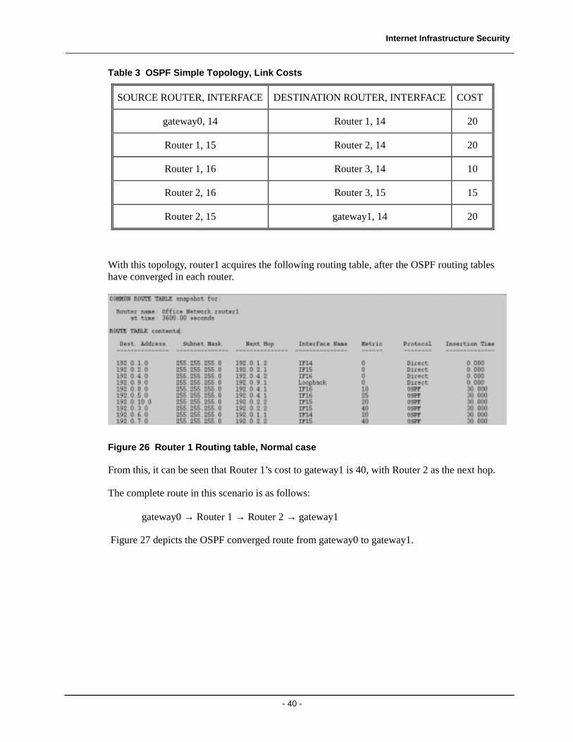
With this topology, router1 acquires the following routing table, after the OSPF routing tables have converged in each router.
Figure 26 Router 1 Routing table, Normal case
From this, it can be seen that Router 1’s cost to gateway1 is 40, with Router 2 as the next hop.
The complete route in this scenario is as follows:
gateway0 → Router 1 → Router 2 → gateway1
Figure 27 depicts the OSPF converged route from gateway0 to gateway1.
Internet Infrastructure Security
- 41 -
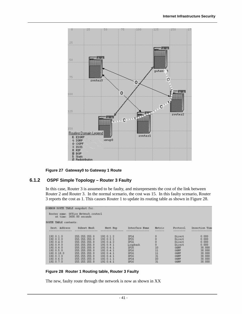
Figure 27 Gateway0 to Gateway 1 Route
6.1.2 OSPF Simple Topology – Router 3 Faulty
In this case, Router 3 is assumed to be faulty, and misrepresents the cost of the link between Router 2 and Router 3. In the normal scenario, the cost was 15. In this faulty scenario, Router 3 reports the cost as 1. This causes Router 1 to update its routing table as shown in Figure 28.
Figure 28 Router 1 Routing table, Router 3 Faulty
The new, faulty route through the network is now as shown in XX
Internet Infrastructure Security
- 42 -
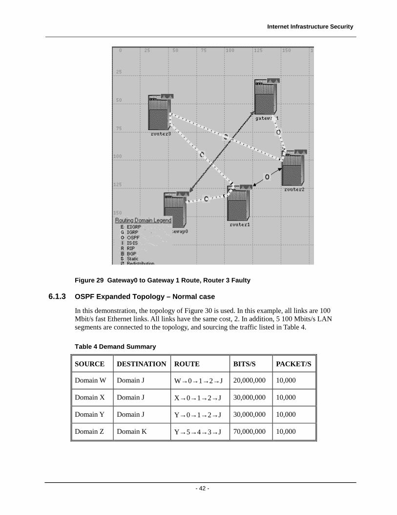
Figure 29 Gateway0 to Gateway 1 Route, Router 3 Faulty
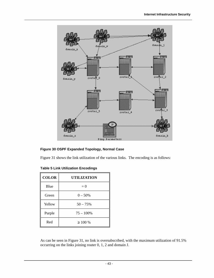
6.1.3 OSPF Expanded Topology – Normal case
In this demonstration, the topology of Figure 30 is used. In this example, all links are 100 Mbit/s fast Ethernet links. All links have the same cost, 2. In addition, 5 100 Mbits/s LAN segments are connected to the topology, and sourcing the traffic listed in Table 4.
Table 4 Demand Summary
SOURCE DESTINATION ROUTE BITS/S PACKET/S
Domain W Domain J W→0→1→2→J 20,000,000 10,000
Domain X Domain J X→0→1→2→J 30,000,000 10,000
Domain Y Domain J Y→0→1→2→J 30,000,000 10,000
Domain Z Domain K Y→5→4→3→J 70,000,000 10,000
Internet Infrastructure Security
- 43 -
Figure 30 OSPF Expanded Topology, Normal Case
Figure 31 shows the link utilization of the various links. The encoding is as follows:
Table 5 Link Utilization Encodings
COLOR UTILIZATION
Blue = 0
Green 0 – 50%
Yellow 50 – 75%
Purple 75 – 100%
Red ≥ 100 %
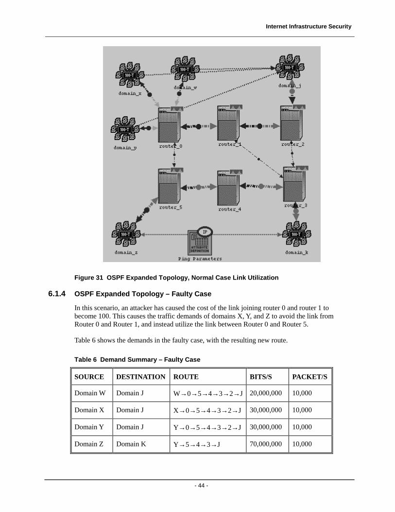
As can be seen in Figure 31, no link is oversubscribed, with the maximum utilization of 91.5% occurring on the links joining router 0, 1, 2 and domain J.
Internet Infrastructure Security
- 44 -
Figure 31 OSPF Expanded Topology, Normal Case Link Utilization
6.1.4 OSPF Expanded Topology – Faulty Case
In this scenario, an attacker has caused the cost of the link joining router 0 and router 1 to become 100. This causes the traffic demands of domains X, Y, and Z to avoid the link from Router 0 and Router 1, and instead utilize the link between Router 0 and Router 5.
Table 6 shows the demands in the faulty case, with the resulting new route.
Table 6 Demand Summary – Faulty Case
SOURCE DESTINATION ROUTE BITS/S PACKET/S
Domain W Domain J W→0→5→4→3→2→J 20,000,000 10,000
Domain X Domain J X→0→5→4→3→2→J 30,000,000 10,000
Domain Y Domain J Y→0→5→4→3→2→J 30,000,000 10,000
Domain Z Domain K Y→5→4→3→J 70,000,000 10,000
Internet Infrastructure Security
- 45 -
Table 6 highlights a few important points:
1. All traffic is now routed through Router 5
2. The number of hops for most demands has increased
3. The total demand traffic attempting to be router through router 5 (and on to Router 4) is now 150 Mbit/s, even though the link bandwidth is at most 100 Mbit/s.
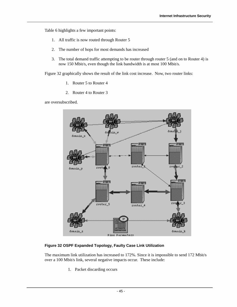
Figure 32 graphically shows the result of the link cost increase. Now, two router links:
1. Router 5 to Router 4
2. Router 4 to Router 3
are oversubscribed.
Figure 32 OSPF Expanded Topology, Faulty Case Link Utilization
The maximum link utilization has increased to 172%. Since it is impossible to send 172 Mbit/s over a 100 Mbit/s link, several negative impacts occur. These include:
1. Packet discarding occurs
Internet Infrastructure Security
- 46 -
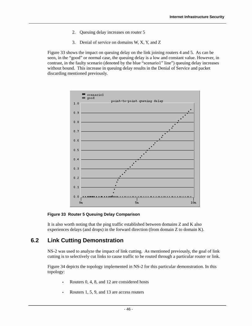
2. Queuing delay increases on router 5
3. Denial of service on domains W, X, Y, and Z
Figure 33 shows the impact on queuing delay on the link joining routers 4 and 5. As can be seen, in the “good” or normal case, the queuing delay is a low and constant value. However, in contrast, in the faulty scenario (denoted by the blue “scenario1” line”) queuing delay increases without bound. This increase in queuing delay results in the Denial of Service and packet discarding mentioned previously.
Figure 33 Router 5 Queuing Delay Comparison
It is also worth noting that the ping traffic established between domains Z and K also experiences delays (and drops) in the forward direction (from domain Z to domain K).
6.2 Link Cutting Demonstration
NS-2 was used to analyze the impact of link cutting. As mentioned previously, the goal of link cutting is to selectively cut links to cause traffic to be routed through a particular router or link.
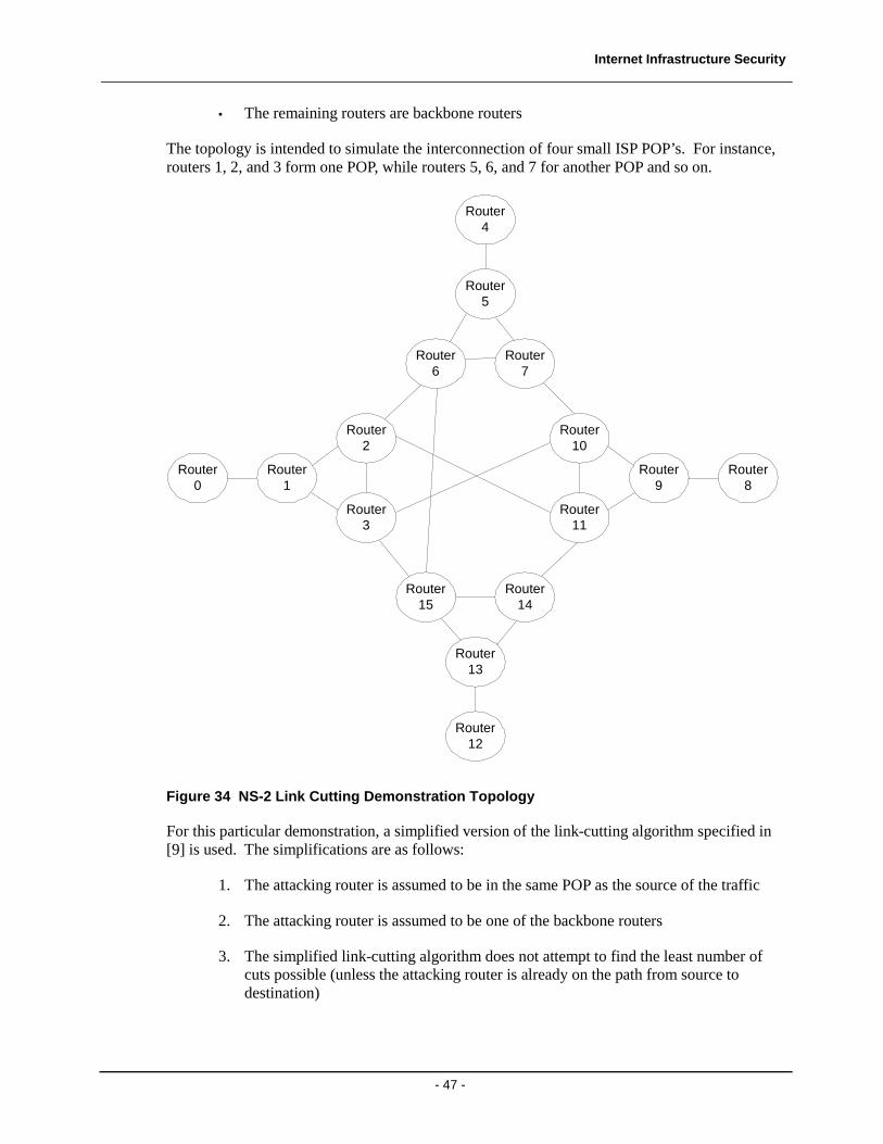
Figure 34 depicts the topology implemented in NS-2 for this particular demonstration. In this topology:
• Routers 0, 4, 8, and 12 are considered hosts
• Routers 1, 5, 9, and 13 are access routers
Internet Infrastructure Security
- 47 -
• The remaining routers are backbone routers
The topology is intended to simulate the interconnection of four small ISP POP’s. For instance, routers 1, 2, and 3 form one POP, while routers 5, 6, and 7 for another POP and so on.
Router1
Router2
Router3
Router0
Router9
Router10
Router11
Router8
Router15
Router14
Router13
Router12
Router6
Router5
Router7
Router4
Figure 34 NS-2 Link Cutting Demonstration Topology
For this particular demonstration, a simplified version of the link-cutting algorithm specified in [9] is used. The simplifications are as follows:
1. The attacking router is assumed to be in the same POP as the source of the traffic
2. The attacking router is assumed to be one of the backbone routers
3. The simplified link-cutting algorithm does not attempt to find the least number of cuts possible (unless the attacking router is already on the path from source to destination)
Internet Infrastructure Security
- 48 -
These simplifications lead to an algorithm that is easier to implement. Further, the algorithm can scale for larger POP’s.
The algorithm is also configurable by the user. The user can select:
1. The source router (among the choices 0, 4, 8, or 12)
2. The destination router (among the choices 0, 4, 8, or 12)
3. The attacking router (one of the two backbone routers in the source routers POP)
The algorithm requires knowledge of the topology, and the routing tables in use. The algorithm performs the following steps:
1. Determine the path from source to destination. If the attacking router is on the path, the algorithm terminates, and no links are cut.
2. If the attacking router is not on the path, the peer backbone router is on the path.
3. The algorithm searches the routing table of the peer backbone router to determine all of its connections to other backbone routers.
4. The algorithm cuts all links from the peer backbone router to all its other peers (both inside and outside the POP, with the exception of the link to the access router).
6.2.1 Link Cutting: Attacker on Path
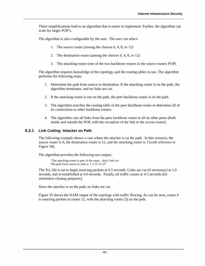
The following example shows a case where the attacker is on the path. In this scenario, the source router is 0, the destination router is 12, and the attacking router is 3 (with reference to Figure 34).
The algorithm provides the following text output:
“The attacking router is part of the route…don’t link cut The path from source to sink is: 1 3 15 13 12”
The TcL file is set to begin sourcing packets at 0.5 seconds. Links are cut (if necessary) at 1.0 seconds, and re-established at 4.0 seconds. Finally, all traffic ceases at 4.5 seconds (for simulation cleanup purposes).
Since the attacker is on the path, no links are cut.
Figure 35 shows the NAM output of the topology with traffic flowing. As can be seen, router 0 is sourcing packets to router 12, with the attacking router (3) on the path.
Internet Infrastructure Security
- 49 -
Figure 35 NS-2 Traffic Flow with Attacker on Path
6.2.2 Link Cutting: Attacker Not on Path
This last example shows a case where the attacker is NOT on the path. In this scenario, the source router is 0, the destination router is 12, and the attacking router is 2 (with reference to Figure 34).
In this example, the algorithm provides an expanded text output that includes the list of links being cut:
“The path from source to sink is: 1 3 15 13 12 The attacking router is NOT part of the route…will cut links The cut list is: 2 2 2 2 10 10 10 10 2 15 15 2 15 15
<list of links to cut> <list of links re-established>
Once again, the TcL file is set to begin sourcing packets at 0.5 seconds. Links are cut at 1.0 seconds, and re-established at 4.0 seconds. Finally, all traffic ceases at 4.5 seconds (for simulation cleanup purposes).
Since the attacker is not on the path, links are cut at the aforementioned time.
Internet Infrastructure Security
- 50 -
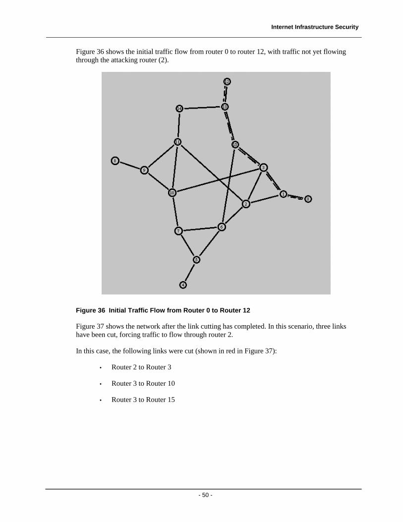
Figure 36 shows the initial traffic flow from router 0 to router 12, with traffic not yet flowing through the attacking router (2).
Figure 36 Initial Traffic Flow from Router 0 to Router 12
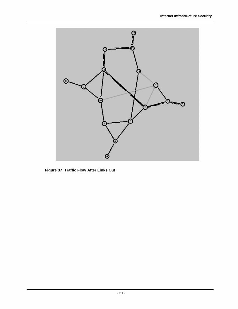
Figure 37 shows the network after the link cutting has completed. In this scenario, three links have been cut, forcing traffic to flow through router 2.
In this case, the following links were cut (shown in red in Figure 37):
• Router 2 to Router 3
• Router 3 to Router 10
• Router 3 to Router 15
Internet Infrastructure Security
- 51 -
Figure 37 Traffic Flow After Links Cut
Internet Infrastructure Security
- 52 -
7 Future Work
This project had several goals:
1. Understand the Internet infrastructure and typical topologies
2. Understand the routing protocols
3. Demonstrate the security holes inherent in the current Internet Infrastructure
4. Inspire future research into routing protocol security
One potential area for future work is to implement S-BGP using NS-2 or OPNET in an attempt to answer the following questions:
• Is it scalable?
• How does it impact routing protocol overhead?
• How does it impact routing table convergence?
• How much additional processing power is required to support the added cryptographic components?
Finally, continued scrutiny of the Internet infrastructure (including routing protocols) is vital to ensure that potential new security holes are closed before they can be exploited.
Internet Infrastructure Security
- 53 -
8 References
[1] J. Moy, “OSPF Version 2”, RFC 2328, April 1998.
[2] Y. Rekhter and P. Gross, “Application of the Border Gateway Protocol in the Internet”, RFC 1772, March 1995.
[3] C. Metz, “Interconnecting ISP Networks”, IEEE Internet Computing, vol. 5, no. 2, March-April 2001, pp 74-80.
[4] S. Kent, C. Lynn, and K. Seo, “Secure Border Gateway Protocol (S-BGP)”, IEEE Journal on Selected Areas in Communications, vol. 18, no. 4, April 2000. pp. 582-592.
[5] S. Kent, C. Lynn, and K. Seo, “Public-key infrastructure for the Secure Border Gateway Protocol (S-BGP)”, Proc. Darpa Information Survivability Conference and Exposition II, vol. 1, June 2001, pp. 239-252.
[6] S. Kent, C. Lynn, and K. Seo, “Design and analysis of the Secure Border Gateway Protocol (S-BGP)”, Proc. Darpa Information Survivability Conference and Exposition II, vol. 1, Jan. 2000, pp 18-33.
[7] H. Papadimitratos, “Securing the Routing Infrastructure”, IEEE Communications Magazine, vol. 40, no. 10, Oct. 2002, pp. 60-68.
[8] A. Chakrabarti, and G. Manimaran, “Internet Infrastructure Security: A Taxonomy”, IEEE Network, vol. 16, no. 6, Nov.-Dec. 2002, pp. 13-21.
[9] S. M. Bellovin, and E. R. Gansner, “Using Link Cuts to Attack Internet Routing”, DRAFT, May 2003.
[10] Rocketfuel, http://www.cs.washington.edu/research/networking/rocketfuel/
[11] Marc Greis’ Tutorial for the UCB/LBNL/VINT Network Simulator “ns”, http://www.isi.edu/nsnam/ns/tutorial/index.html
[12] D. Eastlake, “Domain Name System Security Extensions”, RFC 2535, April 1999.
[13] S Kent, and R. Atkinson, “IP Encapsulating Security Payload (ESP)”, RFC 2406, April 1998.
[14] Cisco Systems White Paper, “Cisco 7600 Series Service Provider Traffic Aggregation”.
Internet Infrastructure Security
- 54 -
9 Appendix – Link Cutting TcL Code #Create a simulator object set ns [new Simulator] #source router: may be 0, 4, 8, or 12 set sourceR 0 #sink router: may be 0, 4, 8, or 12 set sinkR 12 #mal_router: may be 2, 3, 6, 7, 10, 11, 14, or 15 set mal_router 3 #Tell the simulator to use dynamic routing $ns rtproto DV #Open the nam trace file set nf [open out.nam w] $ns namtrace-all $nf #Define a 'finish' procedure proc finish {} { global ns nf $ns flush-trace #Close the trace file close $nf #Execute nam on the trace file exec nam out.nam & exit 0 } #Create four 16 nodes for {set i 0} {$i < 16} {incr i} { set router($i) [$ns node] } # Create Links $ns duplex-link $router(0) $router(1) 1Mb 10ms DropTail $ns duplex-link $router(1) $router(2) 1Mb 10ms DropTail $ns duplex-link $router(1) $router(3) 1Mb 10ms DropTail $ns duplex-link $router(2) $router(3) 1Mb 10ms DropTail $ns duplex-link $router(2) $router(6) 1Mb 10ms DropTail $ns duplex-link $router(2) $router(11) 1Mb 10ms DropTail $ns duplex-link $router(3) $router(10) 1Mb 10ms DropTail $ns duplex-link $router(3) $router(15) 1Mb 10ms DropTail $ns duplex-link $router(4) $router(5) 1Mb 10ms DropTail $ns duplex-link $router(5) $router(6) 1Mb 10ms DropTail $ns duplex-link $router(5) $router(7) 1Mb 10ms DropTail $ns duplex-link $router(6) $router(7) 1Mb 10ms DropTail
Internet Infrastructure Security
- 55 -
$ns duplex-link $router(6) $router(15) 1Mb 10ms DropTail $ns duplex-link $router(7) $router(10) 1Mb 10ms DropTail $ns duplex-link $router(8) $router(9) 1Mb 10ms DropTail $ns duplex-link $router(9) $router(10) 1Mb 10ms DropTail $ns duplex-link $router(9) $router(11) 1Mb 10ms DropTail $ns duplex-link $router(10) $router(11) 1Mb 10ms DropTail $ns duplex-link $router(11) $router(14) 1Mb 10ms DropTail $ns duplex-link $router(12) $router(13) 1Mb 10ms DropTail $ns duplex-link $router(13) $router(14) 1Mb 10ms DropTail $ns duplex-link $router(13) $router(15) 1Mb 10ms DropTail #Create a UDP agent and attach it to node router 0, 4, 8, or 12 set udp0 [new Agent/UDP] $ns attach-agent $router($sourceR) $udp0 set sourceid [$router($sourceR) id] # Create a CBR traffic source and attach it to udp0 set cbr0 [new Application/Traffic/CBR] $cbr0 set packetSize_ 500 $cbr0 set interval_ 0.005 $cbr0 attach-agent $udp0 #Create a Null agent (a traffic sink) and attach it to node router 0, 4, 8, or 12 set null0 [new Agent/Null] $ns attach-agent $router($sinkR) $null0 set sinkid [$router($sinkR) id] #Connect the traffic source with the traffic sink $ns connect $udp0 $null0 $ns compute-routes #Schedule events for the CBR agent and the network dynamics $ns at 0.5 "$cbr0 start" #Following procedure implements the simplified link #cutting procedure. # inputs: sourceid: may be 0, 4, 8, or 12 # sinkid: may be 0, 4, 8, or 12 (but not source_host) # mal_router: may be 2, 3, 6, 7, 10, 11, 14, or 15 # Goal: cut off access to source_host such that traffic MUST go through # mal_router. # Limitation: mal_router MUST BE in same domain as source_router # (ie one of the two backbone routers) set rtable { -1 1 1 1 1 1 1 1 1 1 1 1 1 1 1 1
Internet Infrastructure Security
- 56 -
0 -1 2 3 2 2 2 2 3 3 3 2 3 3 2 3 1 1 -1 3 6 6 6 6 11 11 3 11 11 11 11 3 1 1 2 -1 2 2 2 10 10 10 10 2 15 15 2 15 5 5 5 5 -1 5 5 5 5 5 5 5 5 5 5 5 6 6 6 6 4 -1 6 7 7 7 7 6 6 6 6 6 2 2 2 2 5 5 -1 7 7 7 7 2 15 15 2 15 6 6 6 10 5 5 6 -1 10 10 10 10 6 6 10 6 9 9 9 9 9 9 9 9 -1 9 9 9 9 9 9 9 11 11 11 10 10 10 11 10 8 -1 10 11 11 11 11 10 3 3 3 3 7 7 7 7 9 9 -1 11 11 11 11 3 2 2 2 2 2 2 2 10 9 9 10 -1 14 14 14 2 13 13 13 13 13 13 13 13 13 13 13 13 -1 13 13 13 15 15 15 15 15 15 15 15 14 14 15 14 12 -1 14 15 11 11 11 11 11 11 11 11 11 11 11 11 13 13 -1 13 3 3 3 3 6 6 6 6 3 3 3 3 13 13 13 -1} #first compute the path from source_host to sink_host. If #mal_router is on the list, we're done. Don't do anthing else. set list "" set iCUT "TRUE" set iFlag "FALSE" while {$iFlag == "FALSE"} { set next_hop_index [expr $sourceid*16 + $sinkid] set next_hop [lindex $rtable $next_hop_index] lappend list $next_hop if { $next_hop == $mal_router } { puts "The attacking router is part of the route...don't link cut." set iCUT "FALSE" } if { $next_hop == $sinkid } { puts "The the next hop is the sink_host." set iFlag "TRUE" } else { set sourceid $next_hop } } puts "The path from source to sink is: $list" if {$iCUT == "TRUE"} { # cut all paths leading to the source_host such that traffic goes through # the mal_router. puts "The attacking router is NOT part of the route...will cut links." set cutlist "" set access_router [lindex $list 0] set backbone_index [lindex $list 1] for {set i 0} {$i < 16} {incr i 1} { set backbone_hop_index [expr $backbone_index*16 + $i] set backbone_hop [lindex $rtable $backbone_hop_index] if {$backbone_hop != $access_router} { if {$backbone_hop != -1} {
Internet Infrastructure Security
- 57 -
lappend cutlist $backbone_hop } } } puts "The cut list is: $cutlist" set n [llength $cutlist] # Cut links for {set i 0} {$i < $n} {incr i 1} { set hop_router [lindex $cutlist $i] puts "Cutting link from router $backbone_index to router $hop_router" $ns rtmodel-at 1.0 down $router($backbone_index) $router($hop_router) } # Re-establish links for {set i 0} {$i < $n} {incr i 1} { set hop_router [lindex $cutlist $i] puts "Fixing link from router $backbone_index to router $hop_router" $ns rtmodel-at 4.0 up $router($backbone_index) $router($hop_router) } } $ns at 4.5 "$cbr0 stop" #Call the finish procedure after 5 seconds of simulation time $ns at 5.0 "finish" #Run the simulation $ns run