Embed Size (px)
Citation preview
Transport and Telecommunication Vol.12, No 3, 2011
4
Transport and Telecommunication, 2011, Volume 12, No 3, 4–17 Transport and Telecommunication Institute, Lomonosova 1, Riga, LV-1019, Latvia
INTEROPERABILITY PROBLEMS OF ESPECIALLY ELECTRONIC TOLL COLLECTION
Gabriel Nowacki
Motor Transport Institute,
Management and Transport Telematics Centre Jagiellońska 80, 03–301 Warsaw, Poland,
Phone +48 228113231 ex. 134 E-mail: [email protected]
The paper refers to the implementation problems of Intelligent Transport System (ITS) in Member States of the European Union.
The autonomous systems implemented in Member States of EU are not interoperable due to some reasons, especially lack of cooperation capability. European Commission has taken steps in the mentioned issue (directive 2010/40/EU, M/453, decision 2011). Furthermore the paper discussed assumptions and test results of NATCS Pilot Project developed by Motor Transport Institute, Autoguard SA, and Fela Management AG. Legislation steps were taken at the EC level because of interoperability problems of European Electronic Tolling Service (EETS) in the EU. Commission has urged the member states to conduct studies and pilot projects concerning these issues. Motor Transport Institute has taken up a challenge by developing and testing the pilot project – the functional structure of the NATCS. System has some requirements of EC legislation and it is interoperable with other DSRC and GPS/GSM based systems implemented in the member states of the European Union. Test results have shown a high accuracy and efficacy of the system.
Keywords: Intelligent Transport Systems (ITS), interoperability, the European Electronic Toll Service (EETS), the National Automatic Toll Collection System (NATCS), eCall
1. Introduction
Intelligent Transport Systems or ITS means systems in which information and communication
technologies are applied in the field of the road transport, including infrastructure, vehicles and users, and in traffic management and mobility management, as well as for interfaces with other modes of transport. Interoperability means the capacity of systems and the underlying business processes to exchange data and to share information and knowledge.
Interoperability of ITS is the capacity of systems and the underlying business processes to exchange data and to share information and knowledge. ITS application means an operational instrument for the application of ITS. ITS service is the provision of an ITS application through a well-defined organisational and operational framework with the aim of contributing to user’s safety, efficiency, comfort and/or to facilitate or support the transport and travel operations. ITS service provider means any provider of and ITS service, whether public or private. ITS user is any user of ITS applications or services including travellers, vulnerable road users, road transport infrastructure users and operators, fleet managers and operators of emergency services.
The European Commission has stressed that autonomous Intelligent Transport Systems implemented in EU Member States are not interoperable, means it is no ability of ITS to: − Provide information and services to other systems, − Use exchanged information and services to operate together effectively.
The same situation refers to the European Electronic Tolling Systems (EETS). There are two different types of EETS: Dedicated Short Range Communication (DSRC) and GPS/GSM based systems.
In most EU countries (Austria, France, Spain and Italy) DSRC type systems of electronic tolling are used, that rely on dedicated short range radio (microwave frequency - 5.8 GHz).
The OBU on-board device, operating in the DSRC system is small (size similar to the pack of cigarettes). It is mounted on the windscreen inside the vehicle. However, the device is not very smart, very simple and only performs validation functions (read only), it has no display, and cannot receive or transmit any message. The DSRC system requires a well developed road infrastructure, at every crossroads, and gates must be installed at entrances to and exists from the toll road sections.
In the DSRC system, there are two gates types: communication Toll Gates and control gates, because their number is ten times greater than it is the case in the GPS / GSM.
In addition, data transmission is done using the wired communications, and then it can take place over the Internet. The DSRC system will not be able to be incorporated into an integrated technology platform, as it will not even be able to collaborate with other national transport systems. Even in the case of the DSRC system, which is provided by Kapsch, each country has a different type of OBU device. Another solution is to apply GSM or GPS systems.
Transport and Telecommunication Vol.12, No 3, 2011
5
In this system, thanks to the GPS satellite positioning virtual control and tolling points established, the system can operate without the use of control gates. Data are transferred to the system directly from the OBU devices, using GSM communications.
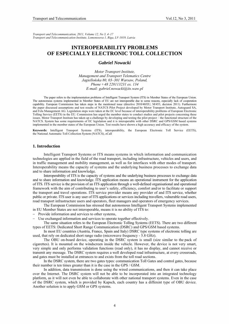
According to the European Commission, the electronic tolling systems used in the European Union are not interoperable for the following reasons: differences in the concepts of tolling, technology standards, classifications, rates, discrepancies in the interpretation of laws (Fig. 1).
Figure 1. Onboard OBU devices currently used on vehicles [5]
The European Commission has taken two mile steps in this regard. The first was Directive 2004/52/EC of 29 April 2004 on the interoperability of electronic road toll systems in the Community [1]. Then there was the decision of the European Commission of 6 October 2009 on definition of the European Electronic Toll Service (EETS), and system architecture [2].
According to the European Commission decision 2009/750/EC, European Electronic Toll Service (EETS) should enable road users to pay tolls easily throughout the whole European Union (EU) thanks to one subscription contract with one Toll Service Provider and one single on-board unit (OBU). The mentioned decision was supported by standard EN ISO 12855 (CEN, Brussels, 05.02.2010) – tolling interoperability aims at enabling a vehicle to driver trough various Toll Domains while having only one OBU operating under contract with Toll Service Provider [8].
Implementation of the interoperability is a long-term and precise action. What comes to the fore in the implementation strategy for interoperability is the need for introduction of the EETS system, consisting of the following systems: DSRC, GSM, GNSS1.
The best universal solution in complicated situation in UE is implementation of hybrid system (includes: DSRC, GSM, GPS technology), the researches developed in Czech Republic, NATCS is mentioned type of system.
2. Problems of Intelligent Transport Systems 2.1. General Characterization of ITS
ITS integrate telecommunications, electronics and information technologies with transport engineering in order to plan, design, operate, maintain and manage transport systems. The application of information and communication technologies to the road transport sector and its interfaces with other
1 GNSS – Global Navigation Satellite System. GNSS-1 is based on existing segments of the orbit Navstar GPS and Russian GLONASS system. An integral part of the GNSS-1 is a system of differential (DGPS - Differential Global Positioning System). Development of GNSS-1 will be the GNSS-2. The constellation of navigation satellites will include the GPS Navstar satellites of II F type GLONASS M and new European satellites wit working name of Galileo.
Transport and Telecommunication Vol.12, No 3, 2011
6
modes of transport will make a significant contribution to improving the environmental performance, efficiency, including energy efficiency, safety and security of the road transport, including transportation of dangerous goods, public security and passenger and freight mobility, whilst at the same time ensuring the functioning of the internal market as well as increased levels of competitiveness and employment. However, ITS applications should be without prejudice to matters concerning national security or which are necessary in the interest of defense.
The general structure of Intelligent Transportation Systems applications may include: vehicle, airplane & ship operations, crash prevention and safety, electronic payment and pricing, emergency management, freeway management, incident management, information management, intermodal freight, road weather management, roadway operations and maintenance, transit management, traveller information.
These are some areas of ITS which are developed by ISO TC 204 (Tab. 1).
Table 1. Category of Intelligent Transportation Systems according to ISO TC 204 [6]
Category of services Service No Service name
1 Pre-trip information 2 On-trip driver information 3 On-trip public transport information 4 Personal information services
Traveler information
5 Route Guidance and Navigation 6 Transportation planning support 7 Traffic control 8 Incident management 9 Demand management
10 Policing/Enforcing traffic regulations
Traffic management
11 Infrastructure maintenance Management 12 Vision enhancement 13 Automated vehicle operation 14 Longitudinal collision avoidance 15 Lateral collision avoidance 16 Safety readiness
Vehicle
17 Pre-crash restrain deployment 18 Commercial vehicle pre-clearance 19 Commercial vehicle administrative process 20 Automated roadside safety inspection 21 Commercial vehicle on-board safety monitoring
Commercial vehicle
22 Commercial vehicle fleet management 23 Public transportation management 24 Demand responsive transport management
Public transport
25 Shared transport management 26 Emergency notification and personal security 27 Emergency vehicle management
Emergency
28 Hazardous Materials and incident notification Electronic Payment 29 Electronic financial transaction
30 Public travel safety 31 Safety enhancement for vulnerable road users
Safety
32 Intelligent junctions
European Intelligent Transport Systems have been fully exploited to maximize the potential of the transport network. European standards will become a key element of the preferred solutions in emerging economies.
Public transport users will have access to up-to-the-minute information, as well as the benefit of smart and seamless ticketing. Freight operators will have real-time information about the entire logistics chain, enabling them to choose the most secure and efficient route for their consignments.
Transport and Telecommunication Vol.12, No 3, 2011
7
Standardization in transport telematics in Europe is dealt with by the following institutions: CEN, ETSI and CENELEC.
CEN (European Standardization Committee) – is a private technical association of a “non-profit” type, operating within a Belgian legislation, with a seat in Brussels. Officially it was formed in 1974, but the beginning of its activities dated back to Paris, 1961. The primary task of CEN is drafting, acceptance and dissemination of the European standards and other standardizing documents in all the spheres of the economy, except electro-technology, electronics and telecommunication. Currently CEN has 30 state members. Polish Standardization Committee (PKN) gained the status of a full CEN member on January 1, 2004.
ETSI – European Institute for the Telecommunication Standards – was formed on the 29 of March 1988, and is the European equivalent of IEEE. The prime objective of ETSI is drafting standards necessary for creation of the European telecommunication market. In 1995 the work of the organization was made international by admitting also the institutions from outside Europe to participate in it.
CENELEC – European Committee for Electro technical Standardization – was formed in 1973. In Poland the role of the State Committee is performed by Polish Standardization Committee – PKN (it is a CENELEC member since 1 of January 2004).
CENELEC together with CEN and ETSI form the European technical standardizing system, whilst international standards come under the jurisdiction of the International Organization for Standardization (ISO) and International Electro technical Commission (IEC).
In 1991, the Technical Committee for Transport Telematics and Road Traffic – CEN/TC 278 (Road Transport and Traffic Telematics) was established.
Also, a world organization – Telecommunication Industry Association has been established, within which, the Technical Committee ISO/TC 204 is responsible for standardization in Transport Telematics (Intelligent Transport Systems).
In the Committee TC 278, as well as in TC 204, there are working groups, which are responsible for various areas of activities – Tab. 2.
Table 2. Areas of activities for TC 278 and TC 204 working groups The activity area TC 278 TC 204 EFC –Electronic fee collection and access control WG 1 WG 5 FFMS – Freight and Fleet Management systems WG 2 WG 7 PT – Public Transport WG 3 WG 8 TTI – Traffic & Traveller Information WG 4 WG 10 TC – Traffic Control WG 5 WG 9 GRD – Geographic road data WG 7 RTD – Road Traffic Data WG 8 DSRC – Dedicated Short Range Communication WG 9 WG 15 HMI – Human-machine Interfaces WG 10 Automatic Vehicle Identification and Automatic Equipment Identification
WG 12 WG 4
Architecture and terminology WG 13 WG 1 After- theft systems for recovery of the stolen vehicles WG 14 Safety WG 15 Data base technology WG3 Navigation systems WG 11 Vehicle/road way warning and control systems WG 14 Wide area communications/protocols and interfaces WG 16 Intermodal aspects using mobile devices for ITS WG 17
The important thing of ITS is optimization of the traffic management. The traffic management
includes controlling the traffic signals depending on the traffic volume by improving the control centres and centralizing traffic signal controls. But other services like the provision of the traffic information or the information service have to be mentioned as well.
ITS can reduce the number of traffic accidents on the expressways and on ordinary roads by supporting the driver's safe driving and improving the pedestrian's safety. Rapid emergency and rescue activities are also included.
2.2. Directive 2010/40/UE
ITS standards define how ITS systems, products, and components can interconnect, exchange information and interact to deliver services within a transportation network. ITS standards are open-interface standards that establish communication rules for how ITS devices can perform, how they can connect, and how they can exchange data in order to interoperate. It is important to note that ITS
Transport and Telecommunication Vol.12, No 3, 2011
8
standards are not design standards: They do not specify specific products or designs to use. Instead, the use of standards gives transportation agencies confidence that components from different manufacturers will work together, without removing the incentive for designers and manufacturers to compete to provide products that are more efficient or offer more features.
The ability of different ITS devices and components to exchange and interpret data directly through a common communication interface, and to use the exchanged data to operate together effectively is called interoperability. Interoperability is a key to achieving the full potential of ITS. Seamless data exchange would allow an emergency services vehicle to notify a traffic management centre to trigger the change in timing the traffic signals on the path to a hospital, in order to assist the responding ambulance.
The main aim of Directive 2010/40/UE [3] is ensured coordinated and coherent deployment of interoperable Intelligent Transport Systems throughout the Union cannot be sufficiently achieved by the Member States and/or the private sector and can therefore, by reason of its scale and effects, be better achieved at the Union level, the Union may adopt measures, in accordance with the principle of subsidiary as set out in Article 5 of the Treaty on European Union. In accordance with the principle of proportionality as set out in that Article, this Directive does not go beyond what is necessary in order to achieve that objective.
The mentioned Directive establishes a framework in support of the coordinated and coherent deployment and use of Intelligent Transport Systems (ITS) within the Union, in particular across the borders between the Member States, and sets out the general conditions necessary for that purpose.
For the purpose of this Directive the following shall constitute the priority areas for the development and use of specifications and standards: – Optimal use of road, traffic and travel data, – Continuity of traffic and freight management ITS services, – ITS road safety and security applications, – Linking the vehicle with the transport infrastructure.
Directive 2010/40/UE stressed the priority areas the following shall constitute the priority actions for the development and use of specifications and standards: – the provision of EU-wide multimodal travel information services, – the provision of EU-wide real-time traffic information services, – data and procedures for the provision, where possible, of road safety related minimum universal
traffic information free of charge to users, – the harmonized provision for an interoperable EU-wide eCall, – the provision of information services for safe and secure parking places for trucks and commercial vehicles, – the provision of reservation services for safe and secure parking places for trucks and commercial vehicles.
According to Commission implementing decision of 13.7.2011 adopting guidelines for reporting by the Member States under Directive 2010/40/EU information of a general report on the activities planned in the next five years related to deployment of ITS in the Member State. This report should include at least the relevant information on the following items: a) a description of the national approach and/or strategy of the development and deployment of ITS,
including its main objectives, b) a description of the technical and legal framework applicable to the development and deployment of ITS, c) a description of the ITS deployment activities, d) a description of the national priority areas for actions and related measures, including an indication
of how these are related to the priority areas, e) the implementation of current and planned actions covering:
– instruments. – resources. – consultation and active stakeholders.
2.3. Mandate 453
The European Commission Mandate M/453 invites the European Standardisation Organisations – ESOs (ETSI, CEN, CENELEC), to prepare a coherent set of standards, technical specifications and technical reports within the timescale required in the Mandate to support European Community wide implementation and deployment of interoperable Co-operative Intelligent Transport Systems
Intelligent Transport Systems (ITS) usage means applying Information and Communication Technologies (ICT) to the transport sector (M/453). ITS can create clear benefits in terms of transport efficiency, sustainability, safety and security, whilst contributing to the EU Internal Market and competitiveness objectives. To take full advantage of the benefits that ICT based systems and applications can bring to the transport sector it is necessary to ensure interoperability among the different systems throughout Europe at least.
Transport and Telecommunication Vol.12, No 3, 2011
9
CEN and ETSI have formally accepted the Mandate in January 2010 and defined the “minimum set of standards”, to be provided in accordance with Mandate M/453, to ensure interoperability of Co-operative ITS – Tab. 3 and 4.
This Mandate supports the development of technical standards and specifications for Intelligent Transport Systems (ITS) within the European Standards Organisations in order to ensure the deployment and interoperability of Co-operative systems, in particular those operating in the 5 GHz frequency band, within the European Community. Standardisation is a priority area for the European Commission in the ITS Action Plan in order to achieve European and global ITS co-operation and coordination.
Standardisation for Cooperative ITS systems has already been initiated both by ETSI and ISO as well as within other international standards organisations. European standardisation activities to provide the standardised solutions for Cooperative ITS services are therefore closely related to the world wide standardisation activities.
Within three months of the date of acceptance of this Mandate ETSI, CEN and CENELEC must present a report to the Commission with the working programme to achieve the goal of completion of the standardization process for Cooperative ITS services.
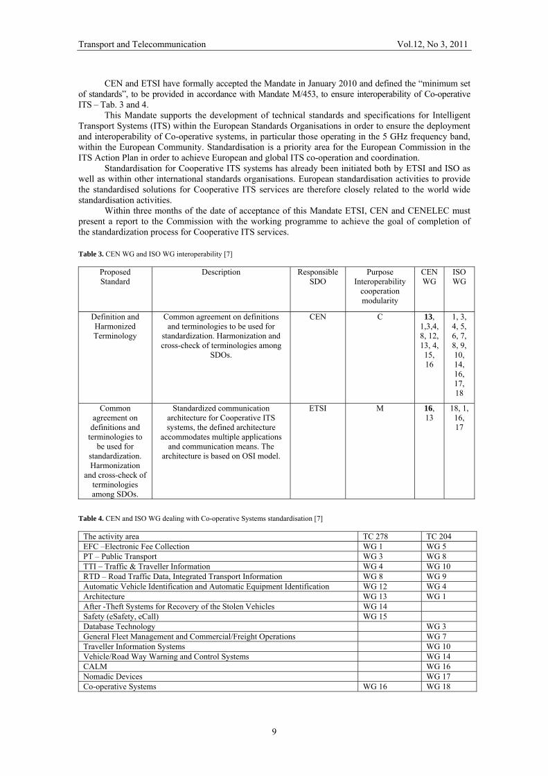
Table 3. CEN WG and ISO WG interoperability [7]
Proposed Standard
Description Responsible SDO
Purpose Interoperability
cooperation modularity
CEN WG
ISO WG
Definition and Harmonized Terminology
Common agreement on definitions and terminologies to be used for
standardization. Harmonization and cross-check of terminologies among
SDOs.
CEN C 13, 1,3,4,8, 12, 13, 4, 15, 16
1, 3, 4, 5, 6, 7, 8, 9, 10, 14, 16, 17, 18
Common agreement on
definitions and terminologies to
be used for standardization. Harmonization
and cross-check of terminologies among SDOs.
Standardized communication architecture for Cooperative ITS systems, the defined architecture
accommodates multiple applications and communication means. The
architecture is based on OSI model.
ETSI M 16, 13
18, 1, 16, 17
Table 4. CEN and ISO WG dealing with Co-operative Systems standardisation [7]
The activity area TC 278 TC 204 EFC –Electronic Fee Collection WG 1 WG 5 PT – Public Transport WG 3 WG 8 TTI – Traffic & Traveller Information WG 4 WG 10 RTD – Road Traffic Data, Integrated Transport Information WG 8 WG 9 Automatic Vehicle Identification and Automatic Equipment Identification WG 12 WG 4 Architecture WG 13 WG 1 After -Theft Systems for Recovery of the Stolen Vehicles WG 14 Safety (eSafety, eCall) WG 15 Database Technology WG 3 General Fleet Management and Commercial/Freight Operations WG 7 Traveller Information Systems WG 10 Vehicle/Road Way Warning and Control Systems WG 14 CALM WG 16 Nomadic Devices WG 17 Co-operative Systems WG 16 WG 18
Transport and Telecommunication Vol.12, No 3, 2011
10
Particular attention must be given to the involvement of all relevant parties, including public authorities, and to the working arrangements between relevant industry forums and consortia.
Within one year of the date of acceptance of this Mandate ETSI, CEN and CENELEC must present a progress report on the achievements in accordance with the working programme. CEN, CENELEC and ETSI must present the annual progress reports to the Commission services.
Twenty months after the acceptance of this mandate a comprehensive report must be presented with the status of the on-going work and the latest available draft of the different standards.
The European Commission mandate on Cooperative Intelligent Transport Systems requires the synchronization among the European Standards Organizations on one hand; on the other hand it recommends collecting feedback from stakeholders affected by that standardization work. This session intends to verify if all the bits and bytes of standardization fit to each other, to identify shortcomings and potential show-stoppers and to find proposals for challenging standardization issues. In addition, the session offers the possibilities to present topics that should be considered by standardization additionally.
Furthermore, within the frame of high level agreements between the European Union, US Department of Transportation and the Japanese communication ministries on global activities to harmonize standardization and cooperative ITS applications as well as a roadmap for deployment, this high level managers round table will provide the latest news on the global activities and discuss the way forward to achieve the global interpretability for cooperative ITS when implemented and deployed in a few years. 3. Polisch Researches of Electronic Toll Collection 3.1. Functional Structure of NATCS
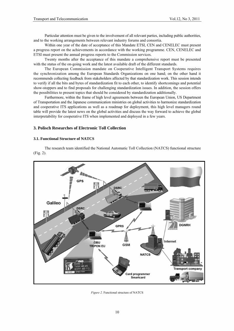
The research team identified the National Automatic Toll Collection (NATCS) functional structure
(Fig. 2).
Figure 2. Functional structure of NATCS
Transport and Telecommunication Vol.12, No 3, 2011
11
NATCS structure consists of the following elements: – Intelligent on-board device called TRIPON-EU, which was installed in test vehicles, – OBU device installation system using a chip card, – two control gates (with DSRC modem and a vision tolling system), – laboratory model of the national Centre for automatic tolling KCAPO, – a proxy server for data exchange between the headquarters and the OBU system via GPRS, – control centre to manage the OBU devices allowing the management of OBU and analyses of the
data relating to the collection of tolls, – analytical tools for DSRC, image analysis and classification of vehicles. The design of the system including the following technologies: – satellite positioning via GPS, and Galileo in the future, – wireless communication via GSM (TS 03.60 / 23.060), – dedicated short range communications – DSRC (5.8 GHz).
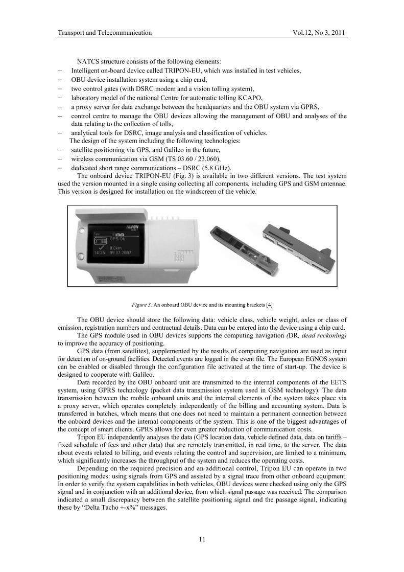
The onboard device TRIPON-EU (Fig. 3) is available in two different versions. The test system used the version mounted in a single casing collecting all components, including GPS and GSM antennae. This version is designed for installation on the windscreen of the vehicle.
Figure 3. An onboard OBU device and its mounting brackets [4]
The OBU device should store the following data: vehicle class, vehicle weight, axles or class of emission, registration numbers and contractual details. Data can be entered into the device using a chip card.
The GPS module used in OBU devices supports the computing navigation (DR, dead reckoning) to improve the accuracy of positioning.
GPS data (from satellites), supplemented by the results of computing navigation are used as input for detection of on-ground facilities. Detected events are logged in the event file. The European EGNOS system can be enabled or disabled through the configuration file activated at the time of start-up. The device is designed to cooperate with Galileo.
Data recorded by the OBU onboard unit are transmitted to the internal components of the EETS system, using GPRS technology (packet data transmission system used in GSM technology). The data transmission between the mobile onboard units and the internal elements of the system takes place via a proxy server, which operates completely independently of the billing and accounting system. Data is transferred in batches, which means that one does not need to maintain a permanent connection between the onboard devices and the internal components of the system. This is one of the biggest advantages of the concept of smart clients. GPRS allows for even greater reduction of communication costs.
Tripon EU independently analyses the data (GPS location data, vehicle defined data, data on tariffs – fixed schedule of fees and other data) that are remotely transmitted, in real time, to the server. The data about events related to billing, and events relating the control and supervision, are limited to a minimum, which significantly increases the throughput of the system and reduces the operating costs.
Depending on the required precision and an additional control, Tripon EU can operate in two positioning modes: using signals from GPS and assisted by a signal trace from other onboard equipment. In order to verify the system capabilities in both vehicles, OBU devices were checked using only the GPS signal and in conjunction with an additional device, from which signal passage was received. The comparison indicated a small discrepancy between the satellite positioning signal and the passage signal, indicating these by “Delta Tacho +-x%” messages.
Transport and Telecommunication Vol.12, No 3, 2011
12
On-board equipment TRIPON-EU uses the built-in GSM antennae; there is no need for external antennae. The SIM card installed inside cannot be replaced by the user. For the convenience of testing, using the S button (send) one may activate a GPRS communication session at any time without having to wait for the next automatically initiated session. The onboard device TRIPON-EU can receive short text messages.
Each received message can be: confirmed, denied, confirmed by way of a predetermined message or deleted by the driver.
For this purpose, the appropriate options in the menu are provided. This functionality has been included to demonstrate easily the potentially available value added services that can be implemented on the platform TRIPON-EU.
The device board TRIPON-EU is equipped with a DSRC module (5.8 GHz, IR) DSRC (Dedicated Short-Range Communications). In cross-border traffic OBU device enables collaboration with GPS/GSM tolling systems (Germany, Slovakia) or DSRC systems used in other countries (Austria, Czech Republic, Italy, Spain, France). The basic standard used in these types of systems (DSRC) is the ISO EN 15509 standard (Media Transactions). The onboard unit TRIPON-EU makes use of such transactions in order to illustrate the possibility of tolling in cooperation with the vision system – ANPR.
Transactions can be configured in such a manner, as to support DSRC attributes that are necessary in a specified tolling implementation.
Each onboard unit TRIPON-EU is equipped with a Smart Card interface, which can be used for calibration and initialisation purposes. When configuring the test system Smart Cards will be used for: initiating onboard units with contract data, configuring parameters of onboard equipment, all operations with the use of the cards can also be initiated via the GSM link.
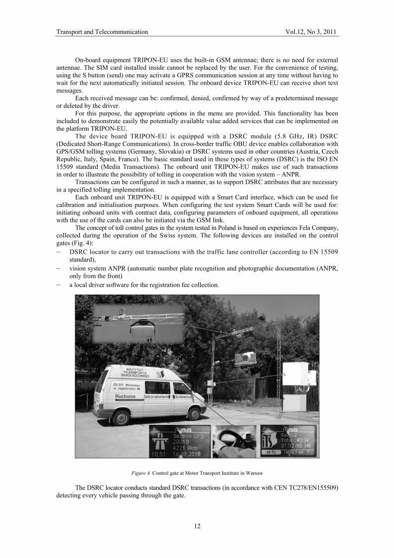
The concept of toll control gates in the system tested in Poland is based on experiences Fela Company, collected during the operation of the Swiss system. The following devices are installed on the control gates (Fig. 4): – DSRC locator to carry out transactions with the traffic lane controller (according to EN 15509
standard), – vision system ANPR (automatic number plate recognition and photographic documentation (ANPR,
only from the front) – a local driver software for the registration fee collection.
Figure 4. Control gate at Motor Transport Institute in Warsaw
The DSRC locator conducts standard DSRC transactions (in accordance with CEN TC278/EN155509) detecting every vehicle passing through the gate.
Transport and Telecommunication Vol.12, No 3, 2011
13
Essentially the contract data are recorded, including the registration numbers and characteristics of the vehicle. The collected data should include in particular: the registration number and characteristics of the vehicle. These data are essential in the process of collection of fees – i.e. they are compared to the data coming from the ANPR (automatic number plate recognition). The DSRC locator is mounted on the top of the gate, about 5–6 meters above the road. In addition to the beacon a so called “traffic lane driver software” should be installed on the gate, which will process data from the locator and control its operation during the transaction. The data should be periodically sent via Ethernet to the system central unit.
Depending on the location of gates and / or traffic conditions one can apply a variety of other triggering signals. The monochromatic ANPR camera will be equipped with an image converter with a resolution of 1620 x 1220 pixels and Gig-E interface. The controller installed inside the camera casing: transmits triggering signals to the camera/impulse source of infrared radiation, converts the signals from light sensor, based on signals from the light sensor generates the parameter settings of the camera / impulse source, controls the temperature in the camera casing (turn on/turn off the heating/cooling)
A photo of vehicle is transmitted to tolling server from a given traffic lane for further processing and is analysed in order to read the registration numbers. At the same time, it will serve as documentation if it is necessary to start tolling procedures.
To enable fully automatic gate operation, an ambient light sensor is used, whose signal is based on the control of the camera and the impulse infrared radiation source. The sensor is oriented on the detection of vehicles and has a dynamic range from 3 to 30,000 lux.
All data collected at toll control are transmitted to the tolling system servers and are made available in the tolling controlling software.
This software enables viewing all collected images, results/details of ANPR algorithm operations and DSRC results.
The laboratory model of National Centre for Automatic Tolling (KCAPO) comprises the following elements: – Three PCs – one dedicated as a database server, the second one serves as application software server,
while the third one is a user terminal, – application and system software, – databases, – software and physical interfaces (between KCAPO and OBU, between KCAPO and control gates), – user interface (online WWW service).
In the proposed solution the proxy server is the main element of the service provider’s interface. It supports and controls OBU sending and receiving all data. The system operates using Linux and ensures the stable operation.
The task of the proxy server should include communication only, but also including SW updates of OBU devices. Toll tariff tables and geographic objects displayed on OBU screen should be sent from a proxy server to the OBU. Data received from the OBU should be checked for consistency, and then made available for analysis.
Databases in KCAPO are divided into the following groups: data on users, vehicles and tariffs, Physical Inventory, Dynamic Inventory.
The design defines a total of six major interfaces that are included in the proposed test system with OBU on-board device. 1. Installation and maintenance contract for the on-board equipment. OBU is configured using
Smartcards. 2. Connecting to the vehicle. OBU is connected to the following points in the installation of vehicle:
power, ground, ignition, tachograph. 3. OBU user interface. The screen displays the following information: the symbol of context (collection
area) Toll (P for Poland), graphical representation of the Polish context of the toll (for example, outline of the borders of the country) declared number of vehicle axles, the total value of toll charged per vehicle run, amount due for passage of the current segment, the time and the amount of kilometres travelled from the time of installation.
4. DSRC Interface (5.8 GHz, IR) is used to conduct the standard transactions with DSRC devices that are installed at tolling gate.
5. Data interface (from the tolling operator to the provider of the system). This is an “internal” interface because there are no isolated places for toll collectors and suppliers of the system in the test system.
6. The tolling procedure was demonstrated with the use of DSRC antennae and ANPR cameras (Automatic Number Plate Recognition) on a test gate installed on a single lane.
Transport and Telecommunication Vol.12, No 3, 2011
14
3.2. Tests results of NATCS
Tests of the KSAPO system, including the control of OBU devices, tolling segments at selected sections of roads as well as control gates were conducted in July and August, while vehicles passing through the control gates were registered from 1st July to 30th November 2010. The tests of the system were conducted by the following research team: – Motor Transport Institute (Gabriel Nowacki, Anna Niedzicka, Ewa Smoczyńska), – FELA Management AG (Thomas Kallweit), – Autoguard SA (Robert Rozesłaniec, Tomasz Garbacz, Krzysztof Pusłowski).
The architecture of the system is in conformity with Directive 2004/52/EC and decision of the European Commission of 6th November 2009 as well as the CE and ISO standards.
During the test four OBU Tripon EU units were examined, whose task was to detect all events associated with the collection of toll directly in OBU, as well as in the log file and display them on the screen. OBU is also meant to send the log files to the proxy server and to receive data from the server (data, status information and software updates.) For testing purposes four vehicles were added to the database.
Out of the several proposed test route options we chose the Płońsk – Garwolin, Garwolin – Płońsk route, as the most diverse one that allows the greatest number of elements of the system for checking, including the both control gates in the immediate vicinity of the route and allowing the use of as many as three actual segments of expressways: – two segments of expressway S7, eastern bypass of Płońsk (a section of 4,7 km), western bypass of
Nowy Dwór Mazowiecki (a section of 14,6 km, Zakroczym – Ostrzykowizna – Czosnów), – one segment of expressway S17, bypass of Garwolin of 12,8 km length with two carriageways, – two segments of the National Roads.
On the basis of the recorded data, transmitted by the vehicle in the form of messages, it was possible to recreate the exact route of the vehicle with the OBU device.
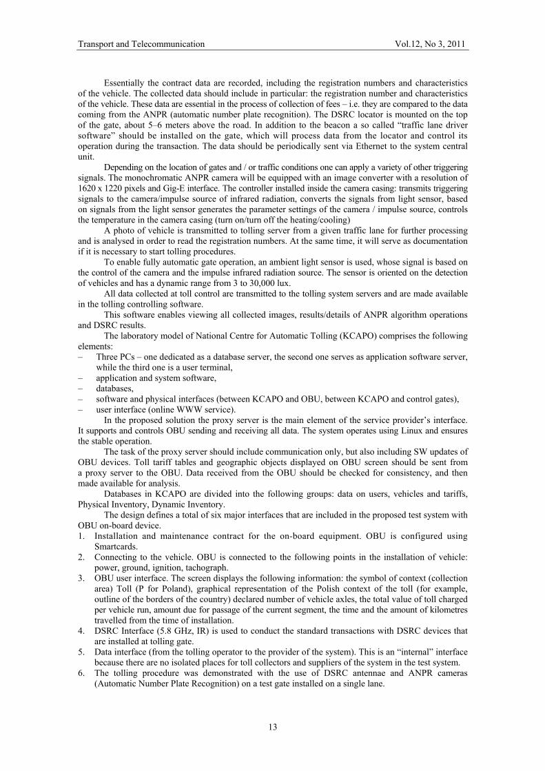
One of the most important parameters determining the accuracy of measurement and transmitted in location messages is PDOP (Position Dilution of Precision) is a defect in determination of position precision. PDOP is a coefficient describing the relationship between the error of user’s position and the error of the satellite position.
The value of any of the parameters equal to 0 means that at any given time measurement of position is impossible due to the interference, weak signals from the satellites, too few visible satellites, etc. The smaller the value of this parameter (but greater than zero), the more accurate is the measurement. The following descriptions signal quality depending on the value of PDOP are assumed: 1 (perfect), 2–3 (excellent), 4–6 (good), 7–8 (moderate), 9–20 (poor), > 20 (bad).
The data of the PDOP parameter obtained in the tests was presented in Fig. 5. The horizontal axis (X) depicts the values for PDOP. The vertical axis (Y) depicts the number of measurements (in percentages) during which a given value of PDOP was obtained. The stats were calculated based on 4627 measurements of position.
Figure 5. Results of PDOP
Average value of PDOP for all OBU was 90% of perfect and 8% excellent values. Analysis of the measurement data of the PDOP parameter and the number of the satellites used during the test showed that 90% of the PDOP measurements were lower than 1, which should provide accuracy of location with error of no more than 6 meters.
Transport and Telecommunication Vol.12, No 3, 2011
15
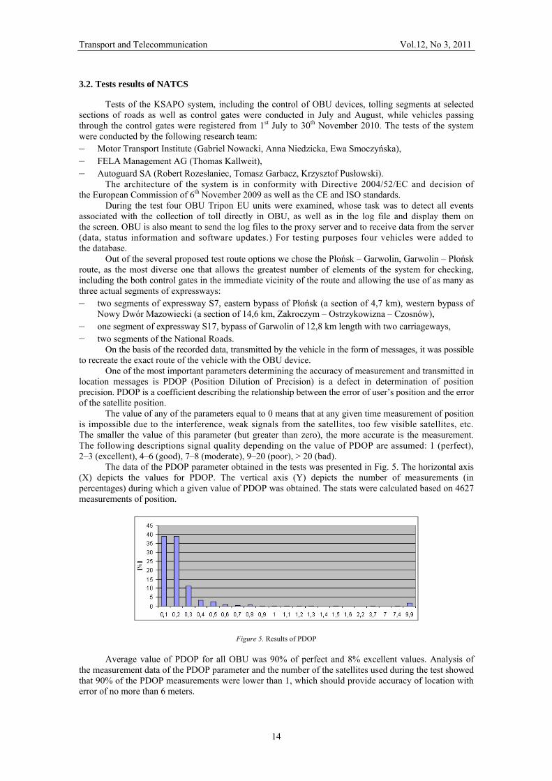
The number of the satellites used for measurements of all OBU devices is presented in Fig. 6. For purposes of KSAPO it was assumed that GPS receiver in OBU should track at least 5 satellites, for more accurate calculations and in the event of loss of signal from one of them.
The presented data show that the maximum number of satellites used in for the purpose of location was 11, and in the case of 99% of measurements at least 5 satellites were used (the detailed results of the satellites: (5–10%, 6–17%, 7–25%, 8–22%, 9–16%, 10–7%, 11–2%).
Figure 6. Number of used satellites for localization
As part of the project two DSRC gates with tolling system were prepared. This has allowed testing of the following functions: – operation of DSRC microwave devices – operation of visual system ANPR system (automatic number plate recognition).
Data obtained from the passage of vehicles through the gates were stored in a separate database. Gates used for testing were described as follows: – ITS Demo (UID = 1000,2), – Autoguard Demo (UID = 1001,3).
From 1st July to 30th November 2010, 2964 vehicles passing through the control gates were registered in the database of the system. Not all vehicles were equipped with OBU.
During the tests at the ITS Demo and Autoguard Demo gates, using the DRSC system, passage of 24 test vehicles was recorded. During the tests at the ITS Demo gate as many as 667 photographs of passing vehicles were taken.
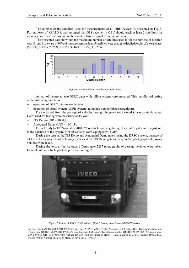
During the tests at the Autoguard Demo gate 2297 photographs of passing vehicles were taken. Example of the vehicle photo is presented in Fig. 7.
Figure 7. Picture of WWY 07512 vehicle, PTM, 5 Przemysłowa Street, 07-200 Wyszków Legend: Date (ANPR): 28.09.2010 09:25:53; Reg. no. (ANPR): WWY 07512; Accuracy: 0.980; Gate ID: 3; Gate name: Autoguard Demo; Date (DSRC): 28.09.2010 09:25:54; Country code: F (France), Registration number (DSRC): WWY 07512; Context data: WWY 07512; OB ID: 1103467888; Vehicle ID: 2147483647; Emission class: 1; Vehicle class: 1; Vehicle weight: 18000; Total weight: 40000; Number of axles: 5; Means of payment: 2147483647.
Transport and Telecommunication Vol.12, No 3, 2011
16
The registered vehicle was equipped with a French made OBU device – Passango (DSRC). It was fully identified in the system as a user, which means that the KSAPO system is interoperable and can work with both, systems of DSRC type as well as GPS / GSM systems.
During each and every passage the operation of control gates as well as the conformity of the DSRC data with the ANPR (automatic number plate recognition) reading was verified. For the purpose of the second stage the onboard OBU devices were replaced with the new ones. Due to a mistake the devices were wrongly installed, however the system immediately discovered the error.
Also the operation of the control gates was tested – mainly with respect to the detection of various vehicle speeds. Thanks to this, it was possible to adjust the software and then to check the newly replaced onboard OBU devices with respect to the correctness of detection of vehicles coming up to the control gate at especially small selected speeds. The system detects vehicles travelling at speeds of 1 to 200 km/h.
In addition to test the drives and the checking of the functionality of them, the efficacy of the gates was checked, recording all vehicles passing at the premises of Motor Transport Institute and at the premises of the AutoGuard company in various weather conditions and at various times of day. The efficacy of automatic detection of number plates was 99,9%. All the segments were identified by the onboard devices correctly, and there were no problems in this respect. Each segment consisted of three points, and in order for each one of them to count, all three segments had to be detected by the OBU device. As a result of this drivers who will cut through toll roads, or only pass through them, will not be registered in the system.
The tests were successful and confirmed the efficacy of the selected solutions in accordance with the assumptions of the project.
4. Conclusions
Intelligent Transport Systems are integral part of European Transport Policy. ITS Directive is the legal instrument for the deployment of ITS in Europe. Standardization has a major role in the development of interoperable ITS. Interoperability and building ITS architecture brings about the necessity to develop the standards concerning, among the others, technical safety solutions as well as data transmission protocols between the system elements and the environment solutions. These applications may provide quick and precise information in the future and allow the safely managing transport. In the forthcoming years they will be further improved by using Galileo system, whose localizing precision will be better than that of GPS. Integration of tools by using standards would allow: reducing times and errors (preventing re-typing), facilitating engineering & trading, improving data recording, improving survey, maintenance and repair (life cycle).
One of the key benefits of ITS is the exchange of information and completion of transactions directly between computers, eliminating the need for processing purchase orders, bills of lading or invoices. Clear, constructive, harmonised, and easy applicable legal rules affect differently the economic parameters of maritime transport than vague and contradictory legal rules or even more the absence of legal provisions. Community legislation now exists for all modes of transport creating new open market conditions.
The European Commission Mandate M/453 on Cooperative Intelligent Transport Systems was approved by CEN and ETSI.
Furthermore, within the frame of high level agreements between the European Union, US Department of Transportation and the Japanese communication ministries on global activities to harmonize standardization and cooperative ITS applications as well as a roadmap for deployment, this high level managers round table will provide the latest news on the global activities and discuss the way forward to achieve the global interpretability for cooperative ITS when implemented and deployed in a few years.
Motor Transport Institute in cooperation with Autoguard SA and Fela Management AG has developed the functional structure of NATCS according to directive 2004/52/EC, decision of European Commission from 6th October 2009 and CEN standards.
During the test of NATCS phase, from 1st July till 30th November 2010, 2964 vehicles passing through the control gates were registered in the database of the system. In addition to testing the drives and checking the functionality, the efficacy of the gates was checked, recording all vehicles passing at the premises of Motor Transport Institute and at the premises of the AutoGuard company in various weather conditions and at various times of day.
The efficacy of automatic detection of number plates was 98%, and thanks to proceeding data by analyze stand, the efficacy of the system increases to 99.9%.
Analysis of the measurement data of the PDOP parameter and the number of satellites used during the test showed that 90% of the PDOP measurements were lower than 1, and 8% had value from 1 to 3.
Transport and Telecommunication Vol.12, No 3, 2011
17
For the purposes of NATCS it was assumed that GPS receiver in OBU should track at least 5 satellites, for more accurate calculations and in the event of the loss of signal from one of them. Tests results showed that in the case of 99% of measurements at least 5 satellites were used for the purpose of location.
The NATCS turned out to be flexible when it comes to extending toll collection to every road category, every category of vehicle and, what is more, in terms of cost efficiency in implementation and operation. Another advantage is an absence of the need for the new road infrastructure (gantries), while the operators can keep using the existing infrastructure. System works without toll booths, extra lanes, speed restrictions or complex structures along toll roads. Furthermore, the system is able to support other value-added services on the same technology platform.
Tests of NATCS project has been a complete success. The system uses GPS/GSM technologies, but also recognises devices such as DSRC and OBU. During tests, the system recognised four Tripon – EU OBU, French made DSRC Passango device and a German made Toll Collect device of the GPS/GSM type, installed in a vehicle which did not participate in the test, but accidentally ran through the control gate. This implies that the NATCS system is interoperable and can cooperate with both GPS/GSM systems as well as with DSRC types of systems existing in other EU Member States.
Acknowledgement: The paper has been prepared with framework of NATCS Pilot Project, N R10 0001 04. References 1. Commission Decision of 6 October 2009 on the definition of the European Electronic Toll Service
and its technical elements. Official Journal of the European Union L 268/11, 13.10.2009. 2. Directive 2004/52/EC of the European Parliament and of the Council of 29 April 2004 on
the interoperability of electronic road toll systems in the Community. OJ of the EU, L 166/132, 30.04.2004.
3. Directive 2010/40/EU of the European Parliament and of the Council of 7 July 2010 on the framework for the deployment of intelligent transport systems in the field of road transport and for interfaces with other modes of transport. Official Journal of the European Union L 207/1.
4. Kallweit, T. Technical Trial of ETC in Poland. Fela Management AG. Diessenhofen. 03/09/2010. 5. Kossak, A. Implemented and Envisaged Road Toll Policies in the Central-Eastern-European Countries.
Seminary – PIARC TC A.3. Budapest, 6–7 May, 2009. 6. McQueen, B. & McQueen, J. Intelligent Transportation Systems Architectures. Artech House, 1999. 7. Schade, H. J. The Mandate on Co-operative ITS and the ITS Directive. CEN. 3rd ETSI TC ITS Workshop,
Venice, 09–11 February 2011. 8. Standard EN ISO 12855. ETC. Information Exchange between Toll Provider and Toll Operator. 2010.