Embed Size (px)
Citation preview
1818 J. Opt. Soc. Am. A/Vol. 11, No. 6/June 1994
Interpretation and experimental demonstrationof twisted Gaussian Schell-model beams
Ari T. Friberg, Eero Tervonen, and Jari Turunen
Department of Technical Physics, Helsinki University of Technology, FIN- 02150 Espoo, Finland
Received September 21, 1993; accepted November 19, 1993
The twisted Gaussian Schell-model (GSM) beams, recently introduced by Simon and Mukunda [J. Opt.Soc. Am. A 9, 95 (1993)], are interpreted in physical-optics terms by decomposition of such beams intoweighted superpositions of overlapping, mutually uncorrelated but spatially coherent component fields. Thedecomposition provides considerable physical insight into the propagation characteristics of the twisted GSMbeams and also suggests convenient practical methods for generating these novel wave fields. Key propertiesof the twisted GSM beams are demonstrated experimentally by use of an acousto-optic coherence controltechnique to supply the necessary partially coherent fields.
INTRODUCTION
A new dimension was contributed to the theory of highlydirectional, partially coherent, Gaussian wave fields bythe recent work of Simon and Mukunda.' These authorspointed out that in free space and in rotationally symmet-ric optical systems the paraxial wave equation permitsthe presence of a previously unnoticed position-dependentphase term that rotates the beam on propagation. Thisnovel twist phase differs in many respects from the cus-tomary quadratic phase factor associated with ordinaryGaussian wave fields. For example, unlike the usualphase curvature, the twist phase is bounded in strengthfrom above, and it disappears in the limit of full coher-ence. The new twist phase was also shown' to producesome nontrivial and observable effects in the propaga-tion of partially coherent Gaussian Schell-model (GSM)beams.2 Although the twist phase does not directly af-fect the beam's transverse coherence length, as measuredin a given plane by the distribution of the complex degreeof spatial coherence, it nevertheless reduces the effectivedegree of spatial coherence and thereby, for example,increases the beam divergence. This effect implies thatthe beam propagation laws carry information about thepresence of the twist.
In this paper our aim is to provide some insight intothe nature of the twisted GSM beams by decomposingsuch beams in terms of spatially coherent but mutuallyuncorrelated fields. Several decomposition methods ofthis type exist for conventional GSM beams. Gori andco-workers3-5 express an anisotropic GSM wave field asa superposition of elliptical Gaussian component beams,which are spatially displaced and propagate parallel toeach other. Alternatively, the component beams mayoccupy the same area in the plane of the beam waistbut propagate in different directions.6' 7 In yet anotherdecomposition method the field is represented as a super-position of the Hermite-Gaussian laser mddes,8 9 whichrepresent the so-called coherent modes'0 of the GSM field.With any of these decompositions, which are mathemati-cally exact, it is possible for the propagation of partiallycoherent waves in free space and through paraxial op-
tical systems to be governed by the standard diffractiontheory of coherent fields. Here we employ one of thesetechniques (Gaussian beams propagating in different di-rections) to illustrate the introduction of the twist phaseinto an anisotropic GSM field as it passes through acertain astigmatic optical system.' This decompositionleads naturally to an understanding of the increased beamspread and, as we shall see below, shows explicitly therotation of the beam on propagation.
In this paper we also demonstrate the twisted GSMbeams experimentally. We do so by implementing theabove-mentioned six-element astigmatic lens system'and passing through it the field radiated by a variable-coherence anisotropic GSM source that is generated bymeans of the real-time acousto-optic coherence-controlmethod.6 " This is a flexible, electronically monitoredholographic technique for synthetizing any desiredpartially coherent field from mutually uncorrelated, fullycoherent laser beams propagating in different directions.The method implements the continuous mathematicalcoherent-beam decomposition in a discrete form. Assuch, it provides a direct and convenient practicaltechnique for illustrating our theoretical interpretationof the nature of twisted GSM beams. The rotation ofthe twisted GSM beam and the increase of the beamdivergence in the presence of the twist phase are verifiedexperimentally.
We begin with a brief introduction to the main charac-teristics of the twisted GSM beams, employing conceptsand notations that differ to some extent from those usedby Simon and Mukunda.' We believe, in particular, thatthe physical-optics approach adopted here is more suit-able for the present purposes. Detailed derivations arenot always provided, because the results agree (wheneverapplicable) with those obtained differently in Ref. 1.
PROPERTIES AN) PRODUCTIONOF TWISTED GAUSSIANSCHELL-MODEL BEAMSSimon and Mukundal show that the most general rota-tionally symmetric Gaussian cross-spectral-density func-
0740-3232/94061818-09$06.00 ©1994 Optical Society of America
Friberg et al
Vol. 11, No. 6/June 1994/J. Opt. Soc. Am. A 1819
tion12 associated with a monochromatic (wavelength A,wave number k = 2in/A) partially coherent optical fieldacross a plane z = constant is of the form
W(p,,p 2 ,z) = Io(2/1ir)w- 2 (z)
X exp[-(p,2
+ p2 2 )/w2(z)]
x exp[- ( - p 2 )2/2oa2 (z)]
x exp[-ik( p12- P22)/2R(z)]
x exp[-ikp, ep2u(z)], (1)
where p = (x,y) is a two-dimensional (column) vectorand the beam is assumed to propagate in the positivez direction. The real-valued functions w(z), (z), andR(z) represent the propagation parameters of a conven-tional GSM beam. They describe the 1/e2 half-width ofthe transverse optical intensity distribution, i.e., the spotsize, the root-mean-square width of the complex degreeof spatial coherence, and the radius of phase curvature,respectively. The axial intensity is Io (2/) w-2 (z), whereIo is a constant (the transversely integrated optical in-tensity). In the last exponential of Eq. (1), which is thenovel aspect of twisted GSM beams, e represents anantisymmetric matrix such that P, EP 2 = xly2 - x2 y1.The effect of this phase term is to rotate the field aboutthe axis of propagation; it is therefore called the twistphase. The strength of the twist phase is measured bythe new propagation parameter u(z), termed the twistparameter. It should be noted that, although Eq. (1) isrotationally symmetric, the twisted GSM beam does notpossess axial symmetry, since the twist phase changessign on reflection in a plane containing the z axis.
To describe the evolution of the beam parametersin compact form, we find it convenient to define twopropagation-invariant quantities,
/3 = {1 + [W(Z)/af(Z)]2,-1, (2)
7 = kar2(z)u(z). (3)
The coherence parameter ,B is normalized between zeroand unity; the upper limit G3 = 1 corresponds to fullycoherent light, whereas - 0 represents the incoherentlimit.'3 The normalized twist parameter 7 is a signedquantity, bounded within the interval -1 c sq c 1. Thesign of 7 is determined by the handedness, and themagnitude of qj is determined by the strength of the twistphase. The upper limit of I I on twisted GSM beams canbe derived from the requirement that the cross-spectraldensity be a nonnegative definite function.'
Assuming that the waist (R = ) of the twisted GSMbeam resides in the plane z = 0, the parameters obey infree space the propagation laws
w(z) = w(0)[1 + (ZIZR)2]
or(z) = a(O)[1 + (ZIZR)2]
R(z) = z[1 + (ZR/Z)2],
u(z) = D()[1 + (Z/ZR)21j1,
(4)
(5)
represents the Rayleigh range of the twisted GSM beam.It reduces to the Rayleigh range of a conventional GSMbeam as 77 - 0 (or ,B - 1); for any value 7 * 0 ( < 1),ZR iS smaller than this limit.
In a rotationally symmetric geometry the twist (or thebeam rotation, which in free space reaches ,r/4 at z = ZR
and reaches r/2 as z - c) cannot be seen directly.'However, the introduction of the twist phase changes thepropagation laws of the other beam parameters accordingto Eq. (8). Therefore, its existence can be verified indi-rectly, e.g., by measurement of the beam divergence onpropagation: the far-field diffraction angle of the twistedGSM beam is
ip - tan = lim w(z)/z = w(0)/zR
A 1 + 72(1 )2]
The relative change in the beam divergence that is dueto the twist is therefore
(A Xtw5t = 1 + ,2(1 /2 ) ] - 1; (10)
i.e., the diffractive beam spreading increases with themagnitude of the twist phase.
The rotationally symmetric twisted GSM beam canbe produced (under certain restrictions that we considerlater) by allowing radiation from an ordinary ellipticGSM source to propagate through an astigmatic opticalsystem.' The conversion system is nonorthogonal, butit can be represented in terms of optical elements thatdo not contain any tilt or decentering. Therefore, toanalyze the conversion optics in physical-optics language,we may adopt the generalized ABCD ray-matrix notationdescribed in Ref. 14. The spatial and directional geo-metric ray coordinates are denoted by two-dimensionalvectors p5 = (u, v) and p,' = (u', v') in the input planeand by po = (x,y) and Po' = (x',y') in the output plane ofthe paraxial optical system. Here the prime effectivelydenotes differentiation, since p' is precisely defined' 4
as p' = n(z)dp/dz, where n(z) represents the refractiveindex. Using this notation, we can express the ray-transfer matrix of an aligned first-order optical systemin convenient block form as
LPo = A B p 1,Po J LC D Lps'
(11)
where each element of the ABCD matrix is a 2 x 2 sub-matrix. The optical field U(p, 0) in the system outputplane is related to the field U 8(p, -zo) in the inputplane at z = -zo by the generalized Fresnel diffractionintegral' 4
,~~~~~~i(6) U(po, 0) = - 2 (det B)-/ 2 exp(ikL)
(7)
where
ZR = ArU (°) p [ + 22(1 -p2) 2]
x ff U 5(p 8 , -zo)exp[ik(poDB-'po
- 2p 8B-'po + p 8B-'Ap8 )/2]d2 p8, (12)
(8) where L is the axial (optical) length. Without losinggenerality, we have assumed that the output plane of
(9)
Friberg et al.
1820 J. Opt. Soc. Am. A/Vol. 11, No. 6/June 1994
fy fx f fy fx f IFig. 1. Astigmatic optical lens system used for converting ananisotropic GSM beam into a twisted GSM beam.
the optical system is the plane z = 0. The lens-systemdiffraction formula [Eq. (12)] may be extended to partiallycoherent fields straightforwardly by use of the definition
W(pbp 2 ,z) = (U*(p1,Z)U(P2 ,Z)) (13)
of the cross-spectral-density function, where the bracketsdenote ensemble averaging.
In this notation, the first-order ray-transfer matrixintroduced by Simon and Mukundal to convert an ellipticGSM source into a twisted GSM beam is of the form
-I
1 0 00 1 n 0o -f- 1 1 0 'V- 1 0 0 1
where fl is a suitable positive parameter. Matrix (14)does not, however, uniquely specify the actual physicalstructure of the conversion system, and several somewhatdifferent realizations can be found. In this study we use,as a basic building block, a group of three cylindricallenses (Fig. 1), two of which form a standard 4f, imagingsystem in one transverse coordinate, and the third (withfocal length f = 2f,) performs a Fourier transform inthe orthogonal direction. The ray-transfer matrices forthe free-space propagation over a distance d and for thetransformation produced by a thin astigmatic lens are,respectively, given by
For implementation of the full conversion system, twosuch blocks are needed, as indicated in Fig. 1, implyingthat zo = 4f in Eq. (12). The latter block is rotated by45° about the common optical axis. This rotation (i.e.,rotation of the coordinate axes and of the second block unitby an angle in the direction from u to v) is described bythe matrix
cos 0
R(O) = -sin 0L o
sin 0cos 0
00
00
cos 0-sin
o0
sin 0 cos ]
(18)
with 0 = r/4. The total ray-transfer matrix of the con-version optics then is
cr' (f) = F(f)R(ir/4)Y(f)
-1 00 1o f'
_fi 0
0
f -1 0
0 1
(19)
This matrix differs from that of Eq. (14) only in the signof the x coordinate, if we set f = fQ. Since the ensuingtwisted GSM beam is rotationally symmetric, such achange of sign is irrelevant in practice (it could be avoidedby addition of another astigmatic image-relay system ofthe type just described).
By combining ray-transfer matrix (19) with Eqs. (12)and (13), we obtain the integral expression [with pls =
(ul, v1) and P2s = ( 2 , 2 )]
W(x1, Yl, X2, Y2, 0)
= (2/f 2 A2)exp[ik(xlyl - X2 y2)/f]
x ffff Ws(l sV1, 2, 2 , -4f)
x exp[-ikV(v 1x1 - u1y1 - 2x2 + U2Y2)/f]
x exp[-ik(ulvl - u2 v2 )/f]du1 dv1du2 dv2 , (20)
I 0 d dD (d ) = O 1 0d ,
0 0 0 1OLo I
1 010 1
L (fV fX) = fX-1 00 -f -l
o o0 01 0 0 1J
for the cross-spectral density of the field leaving theoptical system. This field represents the waist of the
(15) twisted GSM beam. Here WS(u 1, v1,u 2, V2, -4f) denotesthe input cross-spectral density, which is assumed tocorrespond to the waist of a collimated anisotropic GSMbeam (Is is a normalization constant):
(16)
where f and f, denote the focal lengths in the twoorthogonal directions. Hence the ABCD matrix of thesingle unit block is, denoting f = f,
F(f) = D(f/2)L (c,f/2)D(f/2)L (f ,o)
x D (f/2) (c,f/2)D(f/2)
00
-f-i0
O f 0-1 0 0
0 0 0o -1
(17)
Wo(, v1, U2, U2 , -4f)
Is exp[-(U12 + U2 )/Wu]eXp[-(Vi + V22)/W2]
X exp[-(u - 2 )2
/20o-2
]exp[-(v + v2 )2/2 o-
2]. (21)
Below we will describe the coherence properties of theinput beam in the u and directions by the parametersf3, and f,, defined analogously with Eq. (2).
The parameter Q in Eq. (14) has a physical meaning':it is the Rayleigh range of the input GSM source, andtherefore this range must be the same in both directions.Hence, in view of Eq. (8), this implies the relations
f = =ZR 7TWw2'3/A = V7w,2 I3&/A (22)
for the input GSM beam parameters. It is interesting
Friberg et al.
11' = 1,F2
I-
Vol. 11, No. 6/June 1994/J. Opt. Soc. Am. A 1821
to note that an elliptic GSM beam, which satisfies thelast equality of Eq. (22), retains its shape on propagationboth in free space5 and in paraxial, rotationally symmetricoptical systems.' 5
We may evaluate the integrals in Eq. (20) in closedform. On doing so16 we find the expressions
, = , (23)
77 8. _ ) I, (24)
for the propagation-invariant parameters associated withthe twisted GSM beam. Furthermore, the waist size ofthe twisted GSM beam is given by
w 2(0) = 1/2(w. + WU2), (25)
and the twist parameter has the expression
u(O) = [kw 2 (0)1-'(13u - u)/3u (26)
The transverse coherence length c4(0) at z = 0 is obtainedfrom Eqs. (2), (23), and (25) as
a 2(0) = w2(0),6.,j/(1 - j3,I3), (27)
and the phase curvature is zero; i.e., R(0) = co. UsingEqs. (22)-(27), one can design an input beam, whichgenerates a twisted GSM beam with the desired valuesof , and as an output of the astigmatic system. Wenote also that rotation of the second lens block in Eq. (19)by 6 = - iT/4 instead of C = nr/4 changes the signs of u(O)and r (which reverses the twist handedness) but leavesthe beam otherwise unaltered.
Two important observations can be made at this point.If u = fi, we have = 0, i.e., the twist phase disappears.On the other hand, to maximize the magnitude of thetwist phase, i.e., to obtain 1X = 1, we may choose eitherPBu = 1 ( = 1) or /, = 1 (X = -1).
where
U(u, v; C., 03) = I/T exp(-u 2 /wu2 )exp(- v 2/wu2 )x exp(ik~uu)exp(ikCv),
P(01 , 0) = (27r)-lk 2 a 0-r o exp[-'/2(kcr 1 )2 C2]X exp[-'/2 (ka32 Cufl,
(29)
(30)
as we may verify by performing the integrations inEq. (28) and comparing the result with Eq. (21). InEqs. (28)-(30), ,, and C, give the deflection angles ofthe coherent-beam components. As Eq. (28) holds onlywithin the paraxial approximation, on which the entiretheory of beamlike wave fields is based, the integrationlimits have been extended (formally) to infinity.
Inserting Eq. (29) into propagation expression (12) withthe ray-transfer matrix of Eq. (19), we find that the fielddistribution generated by one input-plane componentbeam at the output plane of the twist-generating systemis
U(x,y, O., 0) = A exp[-(x - xo) 2/wx2]exp[-(y - yo) 2 /wy2]
x exp[ic(x - x0)(y - Yo)]
X exp [ik(Cxx + S0y)], (31)
where
A= -i i[I + (2f/kw,,w,) 2]-l 2
x exp(ikL)exp(- ikf 0udu/2), (32)
Wx2 = Wu 2 [1 + (2f/kWuwu,)2]/2,
WY2 = w, 2 [1 + (2f/kww,,) 2]/2,
(33)
(34)
c = (k/f)[1 - (2f /kw.w.) 2]/[1 + (2f /kwuw,,) 2]; (35)
the beam is centered at
(xo, yo) = (-f 0,,/v, f 0u/\½), (36)
and its propagation direction in relation to that of theinput-beam component is given by
(OX, 0) = (-9V/9,jr2_).
INTERPRETATION OF THE TWISTPHASEWe proceed to seek a physical interpretation for thenew phenomena introduced by the presence of the twistphase. We can find such an interpretation by expressingthe anisotropic input GSM beam as a weighted super-position of coherent but mutually uncorrelated ellipticGaussian beams, all of which occupy the same area inthe source plane but propagate in different directions.Several other decompositions exist, as discussed in theIntroduction, but this method is closely connected to theacousto-optic coherence-control technique 6 "' to be used inthe experimental part of this paper.
The decomposition of the anisotropic input field bymeans of Gaussian beams propagating in different direc-tions is of the form
W(ul, V1, U2 , V2) = J f P(O,, O)U (iui, vU; Cu, Cv)
X U(u2,V2;C0,,0,,)dSudC,, (28)
(37)
Apart from a rotation by 450 (in the twist-generating sys-tem) and a scale change that depends on the source-beamsizes as indicated by Eqs. (33) and (34), the intensitydistribution at the output plane is the same as that in theinput plane. However, each coherent component beamhas acquired an aberrated wave front characterized by theterm c(x - x0)(y - yo) in Eq. (31), where the coefficient cdoes not depend on the deflection angles ,, and A,,.
These expressions hold for any beam component[Eq. (29)] in its passage through the astigmatic-lenssystem characterized by Eq. (19). In the process oftwist generation the input-plane beam widths wou andw, are related as indicated in Eq. (22). Taking this intoaccount, we can make in Eqs. (32)-(35) the substitution(2flkw. wj) - ,0,/, where 3,, and /3, are the normalizedcoherence parameters of the elliptic GSM source.
On substituting Eqs. (30) and (31) into Eq. (28) andsetting I = 2Io/7rwxwy, one can verify that the systemoutput field is indeed a twisted GSM source, i.e., of theform of Eq. (1) with z = 0. One can perform the lengthy
Friberg et al.
1822 J. Opt. Soc. Am. A/Vol. 11, No. 6/June 1994
calculations most conveniently by using the coherenceparameters Pu and ,, and recalling Eqs. (25)-(27) for thetwist-beam parameters. For a comparison of the individ-ual coherent-beam properties with those of the twistedGSM field, it is useful to express the component-beamparameters w,, wy, and c in Eqs. (33)-(35) explicitly interms of the twist-beam quantities as
W,2= ZR 2(1 +P'2) (8k [2(1 - 2)2 + 4 p2]12 + 7(1 - 2 (
W 2 = ZR 2(1 + 32) (39)k [72(1 - /32)2 + 4 /32]Y2 - 7(l - 2)
C = (k/zR)(1 - /32)/(1 + /2), (40)
where ZR is given by Eq. (8). The results establishedabove show that the twisted GSM field may be rep-resented rigorously in the form of a continuous super-position of coherent, but mutually uncorrelated, ellip-tic Gaussian beams with aberrated wave fronts; thesebeams are spatially displaced and propagate in differ-ent directions. The origin of this twisted GSM beamsuperposition can be traced back directly (through theastigmatic-lens system) to the corresponding coherentsuperposition of the ordinary elliptic GSM source.
Next we analyze the propagation of the twisted GSMbeam by means of the decomposition derived above.Since the parameters w, wy, and c are independentof the center position and the (paraxial) propagationdirection of the beam component, it suffices to consider thepropagation of a single beam component (e.g., the axialone) in the half-space z > 0. The shape and orientationof all beam components will be the same across any planez = constant, and the center positions are given by
[xo(Z),yo(Z)] = (xo + CXZYo + CyZ). (41)
Inserting Eq. (31) into Eq. (12), where the ray matrixis given by Eq. (15), we can show that the intensitydistribution remains elliptic Gaussian across any planez = constant. If wy < w at z = 0, the ratio wmin/wma, ofthe minor and the major axis lengths, respectively, of theellipse evolves on propagation as
(Wmin/wmax) = [1 - 11 - g(Z)]/[l + / j -rgj ], (42)
where
4/32 (1 + 2)2 (Z2 - ZR2 2]
( + 32)2 L 12(1 - /32)2 +432 2 ZRZ
x [1 + (2 )2]' (43)
and the rotation angle (measured positive in the coun-terclockwise direction) is given by
tan 2t;- ( 2ZRZ [?72(1 - 2)2 + 42]12 (44)\Z2 ZR2) _ y(1+/382)
These formulas result from lengthy calculations thatmake use of formulas (38)-(40). It is interesting to notethat despite some common features, rotation angle (44)differs in general from that of the entire twisted GSM field[cf. Eq. (9.12) of Ref. 1]. This effect is conceivable in view
of the additional displacement of each component beamexpressed by Eq. (41). The propagation characteristicsof twisted GSM beams become more transparent if weanalyze special cases.
We consider the case 171 = 1, i.e., the maximum twist,which implies that either u = 1 or 3,, = 1. Choosingthe latter case ( = -1), as we do in the experimentalpart, we obtain from Eqs. (38) and (39) that w, = w(0)and w, = w(0)/3 = w(0) jA. Furthermore, it can be seenfrom Eqs. (42) and (44) that
Wmin/Wmax = 1 = a
tan 2=- 2 ZRZ2- ZR 2
(45)
(46)
Thus, in this special case, the /e2 width of each compo-nent beam in the x direction is equal to the 1/e2 width ofthe full twisted GSM beam, the ratio of the lengths of theminor and major axes is propagation invariant, and thebeam rotation angle (with respect to the x axis) increasesmonotonically from 0 to 90°, reaching 450 at z = ZR, asit does in the general case. However, at all other valuesof z the rotation angle in the case 17 1 = 1 again differsfrom the corresponding twisted-beam rotation angle, ascalculated by Simon and Mukunda for a twisted GSM fieldthat is squeezed in one direction.l
The condition 171 = 1 implies that a0 = x in Eq. (30).Therefore the decomposition of the anisotropic GSMsource, given by Eqs. (28)-(30), takes the simpler form
W(U, U2, VI, v2 ) = f P(6)U*(Ul, VI; C)U( 2, u2; C)dC,
(47)
where
U(u, v; ) = I/T exp(-s 2 /wu2 )
x exp(-v 2/w02 )exp(ikou),
P(C) = (2rf)-" 2 ka exp[-1/2 (ka) 2 02].
(48)
(49)
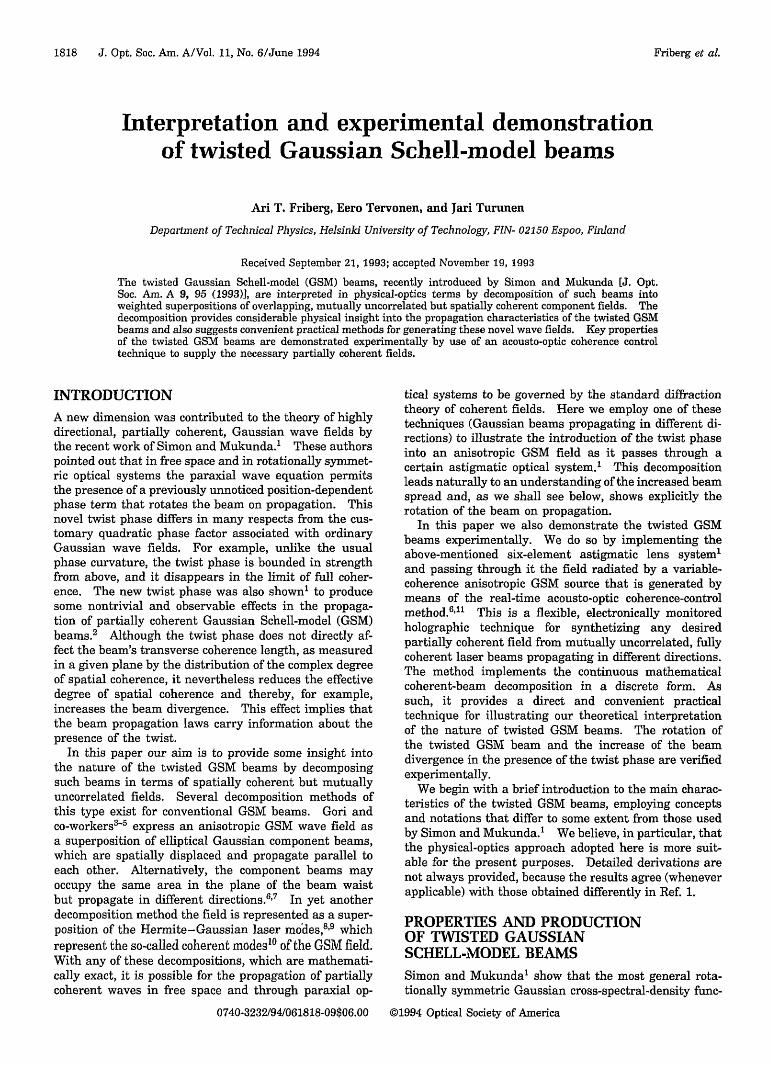
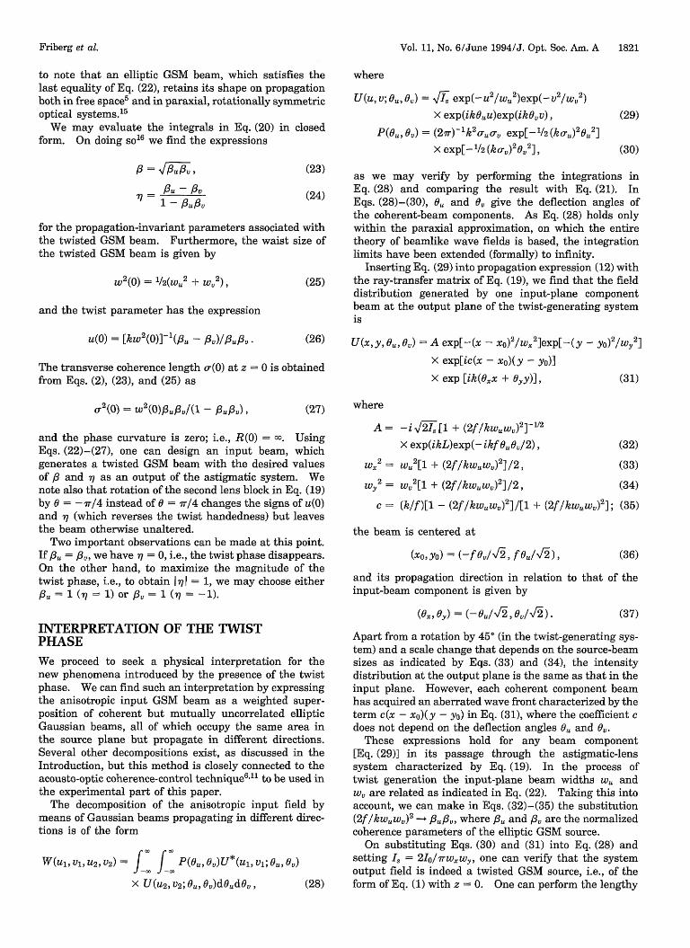
Here the subscripts have been omitted. The resultsgiven above for the case 1?71 = 1 could also have beenobtained directly by substitution of Eq. (48) into Eq. (12):the result is of the form of Eq. (31), with (xo,yo) =(0,f 0/-I2) and (., y) = (- 0/,o ). The coherent-beamdecompositions of an anisotropic GSM source with a, = -(i.e., /3 = 1, -q = - 1) and the corresponding twisted GSMbeam in the output plane of the astigmatic system ofFig. 1 are illustrated in Fig. 2. The arrows emergingfrom the centers of the ellipses represent the propagationdirections of the coherent-beam components; in theu-v plane the fully overlapping beams are deflected inthe is direction, and so in the x-y plane they are displacedin the y direction and propagate at constant y parallel tothe x-z plane.
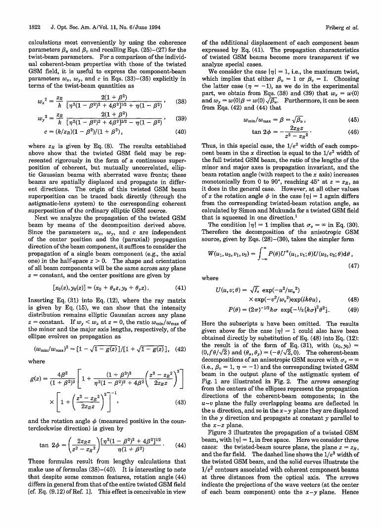
Figure 3 illustrates the propagation of a twisted GSMbeam, with 1 7 I = 1, in free space. Here we consider threecases: the twisted-beam source plane, the plane z = ZR,and the far field. The dashed line shows the 1/a2 width ofthe twisted GSM beam, and the solid curves illustrate thele2 contours associated with coherent component beamsat three distances from the optical axis. The arrowsindicate the projections of the wave vectors (at the centerof each beam component) onto the x-y plane. Hence
Friberg et al.
Vol. 11, No. 6/June 1994/J. Opt. Soc. Am. A 1823
aV
yb
U
z ~~Z
x
Z
Fig. 2 a, Coherent-beam decomposition of an anisotropic GSMsource, which is fully coherent in the v direction: overlap-ping elliptical beams that propagate in different directions.b, Coherent-beam decomposition of a twisted GSM source with77 = -1: spatially shifted elliptical beams that propagate indifferent directions.
Fig. 3a is essentially a head-on view of Fig. 2b. As thecoherent component beams propagate, they move awayfrom the y-z plane and rotate as discussed above. Thediffractive spreading of the component beams and of theresulting twisted beam is manifested in the scale changeof the x and y axes; at the Rayleigh distance the arrowsappear closer to the x axis and coincide with it sufficientlyfar in the far zone.
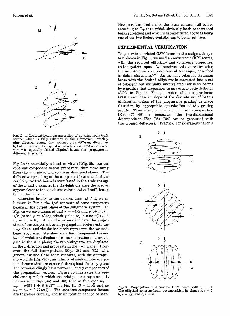
Returning briefly to the general case 171 * 1, we il-lustrate in Fig. 4 the 1/e2 contours of some componentbeams in the output plane of the astigmatic system. InFig. 4a we have assumed that -7 = - 1/2 and a(0)/w(0) =1/2 (hence /3 = 1/V/s), which yields w. = 0.92 w(0) andwy 0.60 w(0). Again the arrows indicate the projec-tions of the component-beam propagation vectors onto thex-y plane, and the dashed circle represents the twisted-beam spot size. We show only four component beams,two of which are displaced in the y direction and propa-gate in the x-z plane; the remaining two are displacedin the x direction and propagate in the y-z plane. How-ever, the full decomposition [Eqs. (28) and (31)] of ageneral twisted GSM beam contains, with the appropri-ate weights [Eq. (30)], an infinity of such elliptic compo-nent beams that are centered throughout the x-y planeand correspondingly have nonzero x and y components ofthe propagation vectors. Figure 4b illustrates the spe-cial case y = 0, in which the twist phase disappears. Itfollows from Eqs. (38) and (39) that in this case wX =
wy = w()[(l + 32)/2]1L2 [in Fig. 4b, /3 = 1/ and sow = y = 0.77w(0)]. The coherent component beamsare therefore circular, and their rotation cannot be seen.
However, the locations of the beam centers still evolveaccording to Eq. (41), which obviously leads to increasedbeam spreading and which was conjectured above as beingone of the two factors contributing to beam rotation.
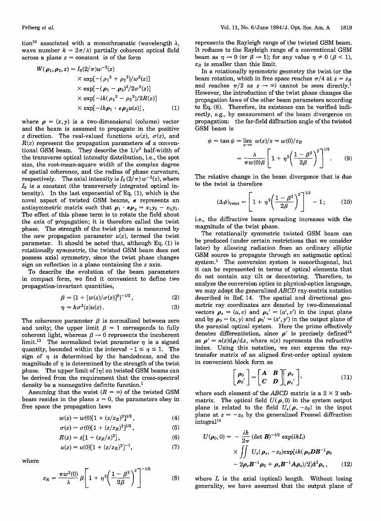
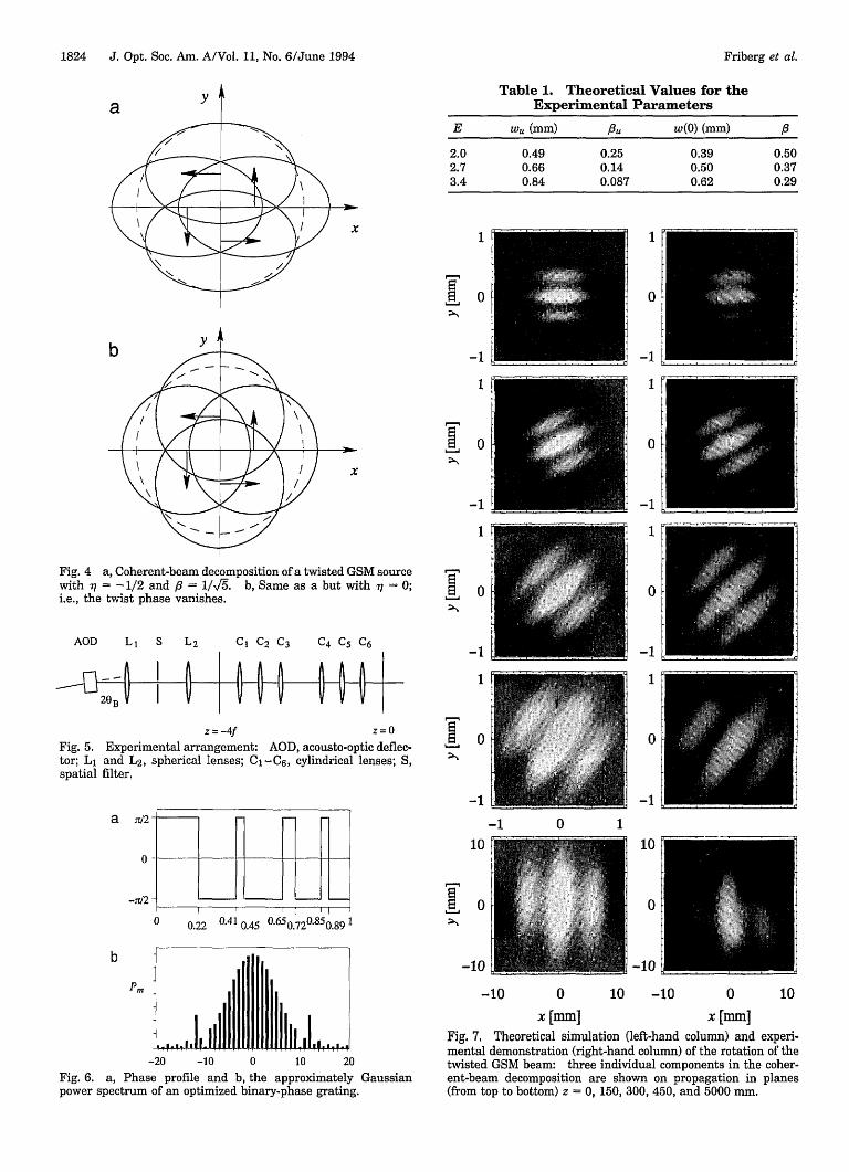
EXPERIMENTAL VERIFICATIONTo generate a twisted GSM beam in the astigmatic sys-tem shown in Fig. 1, we need an anisotropic GSM source,with the required ellipticity and coherence properties,as the system input. We construct this source by usingthe acousto-optic coherence-control technique, describedin detail elsewhere.'61 An incident coherent Gaussianbeam with the desired ellipticity is converted into a setof coherent but mutually uncorrelated Gaussian beamsby a grating that propagates in an acousto-optic deflector(AOD in Fig. 5). For generation of an approximateGSM beam, the envelope of the discrete set of beams(diffraction orders of the progressive grating) is madeGaussian by appropriate optimization of the gratingprofile. Thus a sampled version of the decomposition[Eqs. (47)-(49)] is generated; the two-dimensionaldecomposition [Eqs. (28)-(30)] can be generated withtwo crossed deflectors. Practical considerations favor a
ya
byj
"/7
C
x
/
L
x
x
Fig. 3. Propagation of a twisted GSM beam with 7 = -1.The elliptical coherent-beam decomposition in planes a, z = 0;b, z = ZR; and c, z - .
Friberg et al.
I
1824 J. Opt. Soc. Am. A/Vol. 11, No. 6/June 1994
a YTable 1. Theoretical Values for the
Experimental Parameters
E W" (mm) u w(0) (mm) ,B
2.0 0.49 0.25 0.39 0.502.7 0.66 0.14 0.50 0.373.4 0.84 0.087 0.62 0.29
x 1
0
-1
1
0
-1
1
Fig. 4 a, Coherent-beam decomposition of a twisted GSM sourcewith 77 = -1/2 and = 1/I. b, Same as a but with -q = 0;i.e., the twist phase vanishes.
AOD L1 S L2 Cl C2 C3 C4 C5 C6
a-- I h
z= -4f
Fig. 5.tor; L1spatial
Z=0
Experimental arrangement: AOD, acousto-optic deflec-and L2 , spherical lenses; C-C 6 , cylindrical lenses; S,filter.
a /2
0
-b2
b
Pm
0 0.22 0.41 0.45 0650.720.850.89 1
LLLLW-20 -10 0 10 20
Fig. 6. a, Phase profile and b, the approximately Gaussianpower spectrum of an optimized binary-phase grating.
1
0
-1
1
0
-11
0
-1
1
0
-1
0
-1
1
0
-1
10
0
-10
-1 0 1
10
0
-10
-10 0 10 -10 0 10
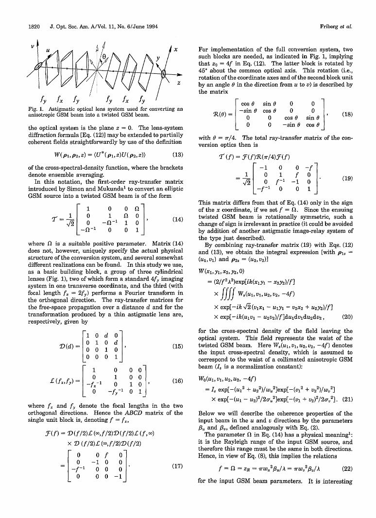
x [mm] x [mm]Fig. 7. Theoretical simulation (left-hand column) and experi-mental demonstration (right-hand column) of the rotation of thetwisted GSM beam: three individual components in the coher-ent-beam decomposition are shown on propagation in planes(from top to bottom) z = 0, 150, 300, 450, and 5000 mm.
I I I I I I I
Friberg et al.
I
0
Vol. 11, No. 6/June 1994/J. Opt. Soc. Am. A 1825
C
-1
a
JAP
CoMP4L
0 1
M [mb , =X, y
-1
a
upY
0
-1
CoAP4L
1 -1
a4~
0
0
-1 0 1 -1 0t [mm], =x,y Y [mm], =X, y
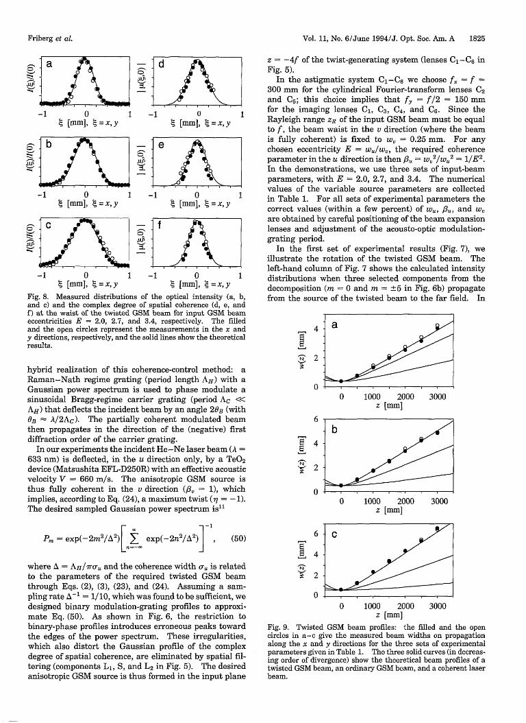
Fig. 8. Measured distributions of the optical intensity (a,and c) and the complex degree of spatial coherence (d, e, a:f) at the waist of the twisted GSM beam for input GSM beEeccentricities E = 2.0, 2.7, and 3.4, respectively. The filland the open circles represent the measurements in the x ay directions, respectively, and the solid lines show the theoreticresults.
z = -4f of the twist-generating system (lenses C1 -C 6 inFig. 5).
In the astigmatic system C-C 6 we choose /U = f =
300 mm for the cylindrical Fourier-transform lenses C2and C; this choice implies that f = f/2 = 150 mmfor the imaging lenses C, C3, C4, and C6. Since theRayleigh range ZR of the input GSM beam must be equalto f, the beam waist in the v direction (where the beamis fully coherent) is fixed to w = 0.25 mm. For anychosen eccentricity E = w/w,, the required coherenceparameter in the u direction is then 6/t = w, 2 /w.2 = l/E 2 .
In the demonstrations, we use three sets of input-beamparameters, with E = 2.0, 2.7, and 3.4. The numericalvalues of the variable source parameters are collectedin Table 1. For all sets of experimental parameters thecorrect values (within a few percent) of wu, /3U, and w,are obtained by careful positioning of the beam expansionlenses and adjustment of the acousto-optic modulation-grating period.
In the first set of experimental results (Fig. 7), weillustrate the rotation of the twisted GSM beam. Theleft-hand column of Fig. 7 shows the calculated intensitydistributions when three selected components from thedecomposition (m = 0 and m = ±5 in Fig. 6b) propagate
b, from the source of the twisted beam to the far field. Inndamledad,al
N
hybrid realization of this coherence-control method: aRaman-Nath regime grating (period length AH) with aGaussian power spectrum is used to phase modulate asinusoidal Bragg-regime carrier grating (period Ac <<AH) that deflects the incident beam by an angle 2 0 B (withOB A/2Ac). The partially coherent modulated beamthen propagates in the direction of the (negative) firstdiffraction order of the carrier grating.
In our experiments the incident He-Ne laser beam (A =633 nm) is deflected, in the u direction only, by a TeO2device (Matsushita EFL-D250R) with an effective acousticvelocity V = 660 m/s. The anisotropic GSM source isthus fully coherent in the v direction ( = 1), whichimplies, according to Eq. (24), a maximum twist (- = -1).The desired sampled Gaussian power spectrum is"1
4
2
0
6
4
2
0
0 1000 2000 3000z [mm]
0 1000 2000z [mm]
3000
Pm = exp(-2m2/A2)L exp(-2n2/2) , (50)n=-
where A = AH/1raC and the coherence width aU is relatedto the parameters of the required twisted GSM beamthrough Eqs. (2), (3), (23), and (24). Assuming a sam-pling rate A`' = 1/10, which was found to be sufficient, wedesigned binary modulation-grating profiles to approxi-mate Eq. (50). As shown in Fig. 6, the restriction tobinary-phase profiles introduces erroneous peaks towardthe edges of the power spectrum. These irregularities,which also distort the Gaussian profile of the complexdegree of spatial coherence, are eliminated by spatial fil-tering (components L1, S, and L2 in Fig. 5). The desiredanisotropic GSM source is thus formed in the input plane
6
4
2
00 1000 2000 3000
z [mm]
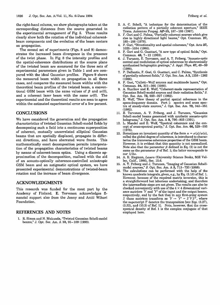
Fig. 9. Twisted GSM beam profiles: the filled and the opencircles in a-c give the measured beam widths on propagationalong the x and y directions for the three sets of experimentalparameters given in Table 1. The three solid curves (in decreas-ing order of divergence) show the theoretical beam profiles of atwisted GSM beam, an ordinary GSM beam, and a coherent laserbeam.
dA.a
__J. . .
.b
.I -.0
C I
- I
Friberg et al.
. I
1826 J. Opt. Soc. Am. A/Vol. 11, No. 6/June 1994
the right-hand column, we show photographs taken at thecorresponding distances from the source generated inthe experimental arrangement of Fig. 5. These resultsclearly show both the rotation of the individual coherent-beam components and the evolution of the beam centerson propagation.
The second set of experiments (Figs. 8 and 9) demon-strates the increased beam divergence in the presenceof the twist phase. In Fig. 8 the intensity profiles andthe spatial-coherence distributions at the source planeof the twisted beam are measured for the three sets ofexperimental parameters given in Table 1 and are com-pared with the ideal Gaussian profiles. Figure 9 showsthe measured beam width on propagation in all threecases, and compares the measured beam widths with thetheoretical beam profiles of the twisted beam, a conven-tional GSM beam with the same values of /3 and w(O),and a coherent laser beam with the same w(O). Theexperimental and the theoretical results are seen to agreewithin the estimated experimental error of a few percent.
CONCLUSIONS
We have considered the generation and the propagationcharacteristics of twisted Gaussian Schell-model fields bydecomposing such a field into a continuous superpositionof coherent, mutually uncorrelated elliptical Gaussianbeams that are spatially displaced, propagate in differ-ent directions, and have aberrated wave fronts. Thismathematically exact decomposition permits interpreta-tion of the propagation characteristics of twisted beamsby means of coherent-beam optics. Using a discrete ap-proximation of the decomposition, realized with the aidof an acousto-optically coherence-controlled anisotropicGSM beam and an astigmatic optical system, we havepresented experimental demonstrations of twisted-beamrotation and the increase of beam divergence.
ACKNOWLEDGMENTSThis research was funded for the most part by theAcademy of Finland. E. Tervonen acknowledges fi-nancial support also from the Jenny and Antti WihuriFoundation.
REFERENCES AND NOTES1. R. Simon and N. Mukunda, "Twisted Gaussian Schell-model
beams," J. Opt. Soc. Am. A 10, 95-109 (1993).
2. A. C. Schell, A technique for the determination of theradiation pattern of a partially coherent aperture," IEEETrans. Antennas Propag. AP-1S, 187-188 (1967).
3. F. Gori and C. Palma, "Partially coherent sources which giverise to highly directional light beams," Opt. Commun. 27,185-188 (1978).
4. F. Gori, "Directionality and spatial coherence," Opt. Acta 27,1025-1034 (1980).
5. F. Gori and G. Guattari, "A new type of optical fields," Opt.Commun. 48, 7-12 (1983).
6. J. Turunen, E. Tervonen, and A. T. Friberg, "Acousto-opticcontrol and modulation of optical coherence by electronicallysynthesized holographic gratings," J. Appl. Phys. 67, 49-59(1990).
7. P. DeSantis, F. Gori, G. Guattari, and C. Palma, "Synthesisof partially coherent fields," J. Opt. Soc. Am. A3, 1258-1262(1986).
8. F. Gori, "Collett-Wolf sources and multimode lasers," Opt.Commun. 34, 301-305 (1980).
9. A. Starikov and E. Wolf, "Coherent-mode representation ofGaussian Schell-model sources and their radiation fields," J.Opt. Soc. Am. 72, 923-927 (1982).
10. E. Wolf, New theory of partial spatial coherence in thespace-frequency domain. Part I: spectra and cross spec-tra of steady-state sources," J. Opt. Soc. Am. 72, 343-351(1982).
11. E. Tervonen, A. T. Friberg, and J. Turunen, GaussianSchell-model beams generated with synthetic acousto-opticholograms," J. Opt. Soc. Am. A 9, 796-803 (1991).
12. L. Mandel and E. Wolf, Spectral coherence and the con-cept of cross-spectral purity," J. Opt. Soc. Am. 66, 529-535(1976).
13. Sometimes an invariant quantity of the form a = a(z)/w(z),called the global degree of coherence, is introduced to charac-terize the transverse coherence properties of the GSM beam.However, it is evident that this quantity is not normalized.Note also that the parameter p defined in Eq. (2) is not thesame as the parameter is of Ref. 1; the latter corresponds toour 1/2a.
14. A. E. Siegman, Lasers (University Science Books, Mill Val-ley, Calif, 1986), Sec. 15.6.
15. A. T. Friberg and J. Turunen, "Imaging of Gaussian Schell-model sources," J. Opt. Soc. Am. A 5, 713-720 (1988).
16. The calculations can be performed with the help of theknown quadratic integrals, given, e.g., by Eq. (3.16) of Ref. 1.However, because of the required matrix inversion, this isa straightforward but laborious undertaking, and thereforethe intermediate steps are not given. The results can also bechecked conveniently with use of the 4 x 4 dimensional vari-ance matrices V and -V of the input and the output beams,respectively, and by the fact that in any first-order systemS these matrices transform as V -g V) = S-VST, wherethe superscript T denotes the transposition [see Eqs. (3.27),(3.32), and (10.3) of Ref. 1]. Note, however, that the cross-spectral density of Ref. 1 is the complex conjugate of thatemployed here.
Friberg et al.