Embed Size (px)
Citation preview
Interrupts
Chapter 20S. Dandamudi
2003To be used with S. Dandamudi, “Fundamentals of Computer Organization and Design,” Springer, 2003.
S. Dandamudi Chapter 20: Page 2
Outline
• What are interrupts?• Types of interrupts
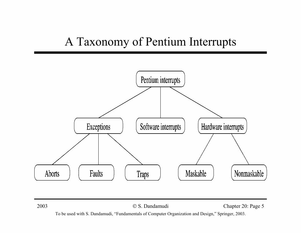
∗ Software interrupts∗ Hardware interrupts∗ Exceptions
• Interrupt processing∗ Protected mode∗ Real mode
• Software interrupts∗ Keyboard services
» int 21H DOS services» int 16H BIOS services
• Exceptions∗ Single-step example
• Hardware interrupts∗ Accessing I/O∗ Peripheral support chips
• Writing user ISRs• Interrupt processing in
PowerPC• Interrupt processing in
MIPS
2003To be used with S. Dandamudi, “Fundamentals of Computer Organization and Design,” Springer, 2003.
S. Dandamudi Chapter 20: Page 3
What Are Interrupts?
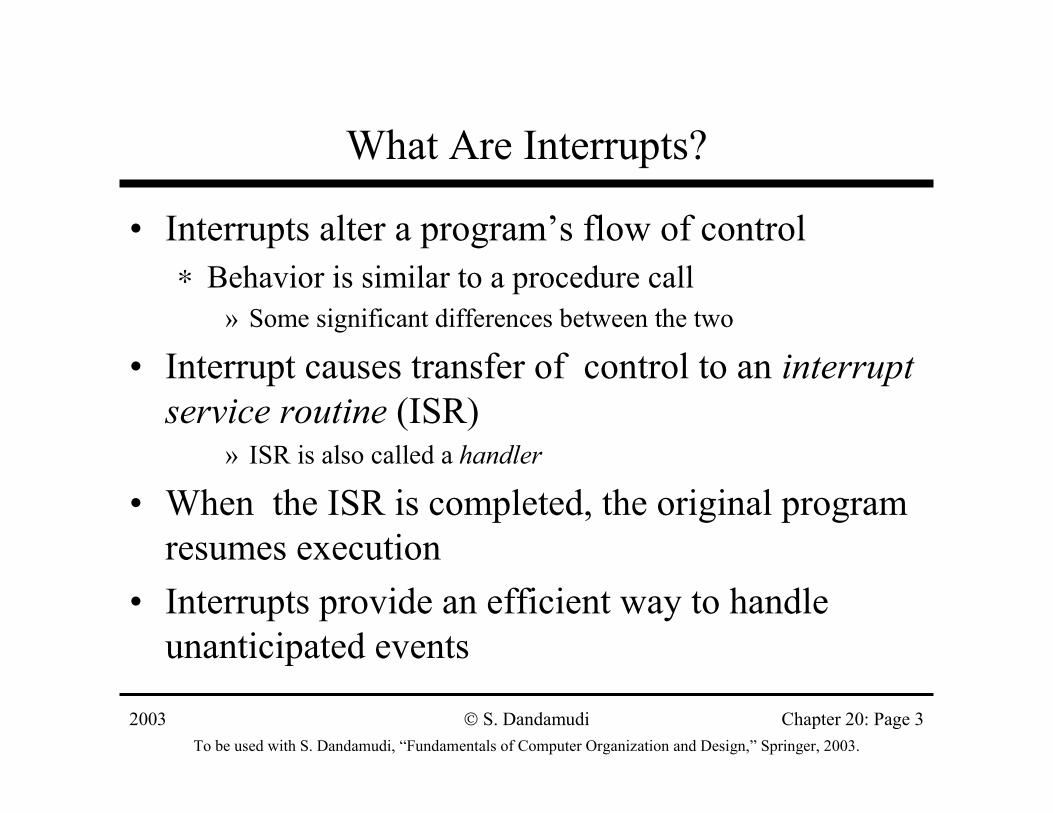
• Interrupts alter a program’s flow of control∗ Behavior is similar to a procedure call
» Some significant differences between the two
• Interrupt causes transfer of control to an interrupt service routine (ISR)
» ISR is also called a handler
• When the ISR is completed, the original program resumes execution
• Interrupts provide an efficient way to handle unanticipated events
2003To be used with S. Dandamudi, “Fundamentals of Computer Organization and Design,” Springer, 2003.
S. Dandamudi Chapter 20: Page 4
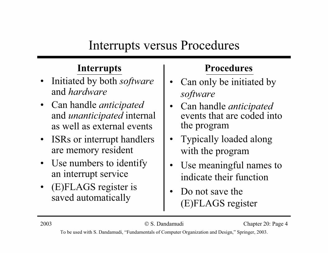
Interrupts versus ProceduresInterrupts
• Initiated by both softwareand hardware
• Can handle anticipatedand unanticipated internal as well as external events
• ISRs or interrupt handlers are memory resident
• Use numbers to identify an interrupt service
• (E)FLAGS register is saved automatically
Procedures• Can only be initiated by
software• Can handle anticipated
events that are coded into the program
• Typically loaded along with the program
• Use meaningful names to indicate their function
• Do not save the (E)FLAGS register
2003To be used with S. Dandamudi, “Fundamentals of Computer Organization and Design,” Springer, 2003.
S. Dandamudi Chapter 20: Page 5
A Taxonomy of Pentium Interrupts
2003To be used with S. Dandamudi, “Fundamentals of Computer Organization and Design,” Springer, 2003.
S. Dandamudi Chapter 20: Page 6
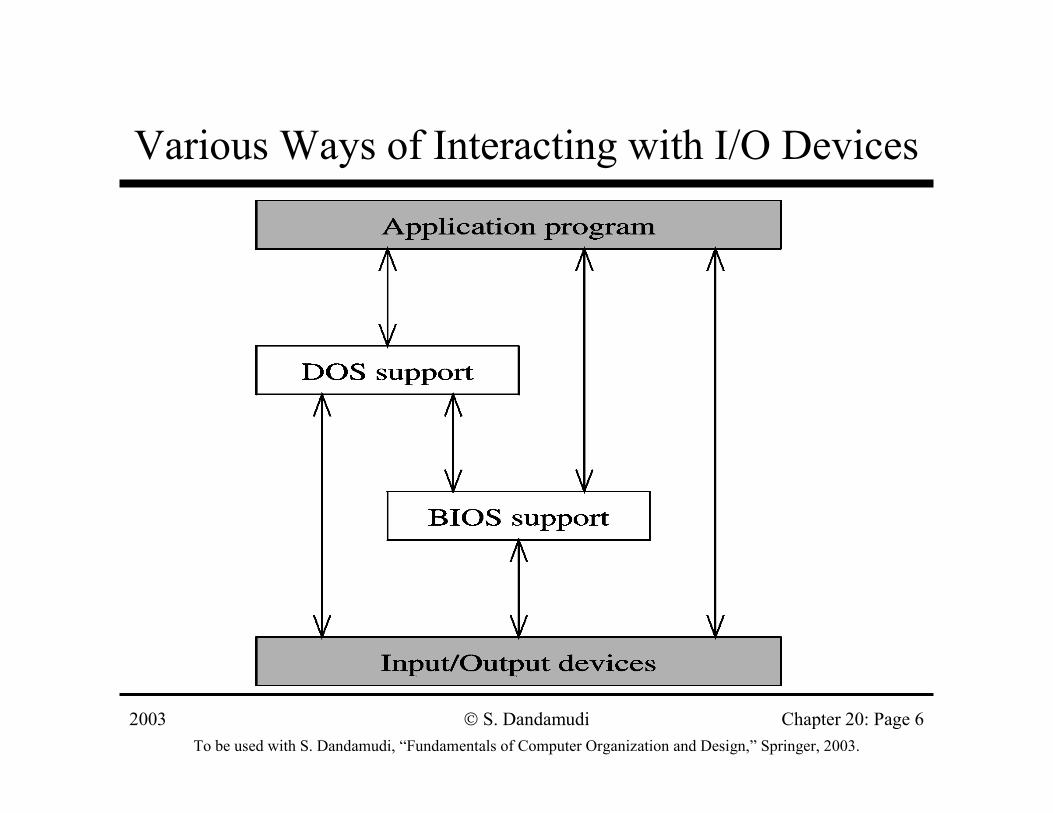
Various Ways of Interacting with I/O Devices
2003To be used with S. Dandamudi, “Fundamentals of Computer Organization and Design,” Springer, 2003.
S. Dandamudi Chapter 20: Page 7
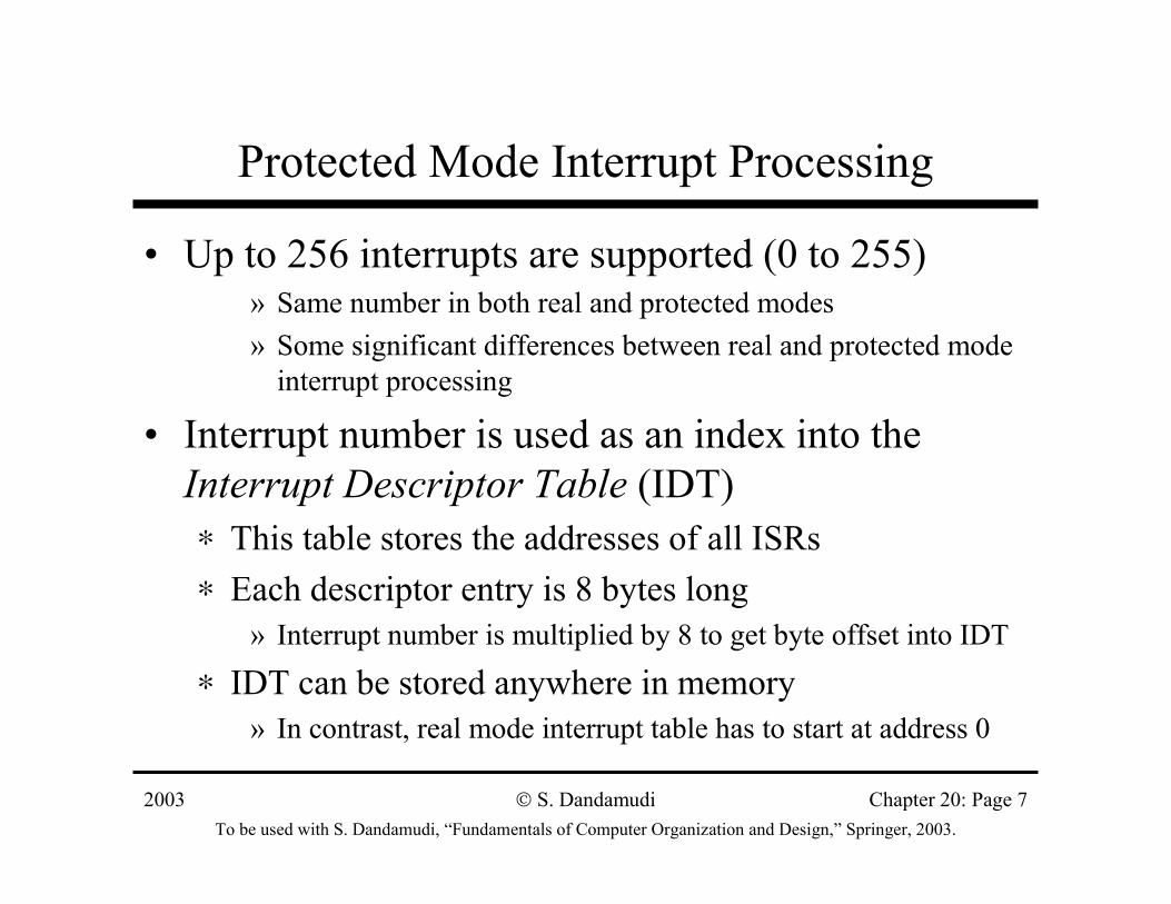
Protected Mode Interrupt Processing
• Up to 256 interrupts are supported (0 to 255)» Same number in both real and protected modes» Some significant differences between real and protected mode
interrupt processing
• Interrupt number is used as an index into the Interrupt Descriptor Table (IDT)∗ This table stores the addresses of all ISRs∗ Each descriptor entry is 8 bytes long
» Interrupt number is multiplied by 8 to get byte offset into IDT
∗ IDT can be stored anywhere in memory» In contrast, real mode interrupt table has to start at address 0
2003To be used with S. Dandamudi, “Fundamentals of Computer Organization and Design,” Springer, 2003.
S. Dandamudi Chapter 20: Page 8
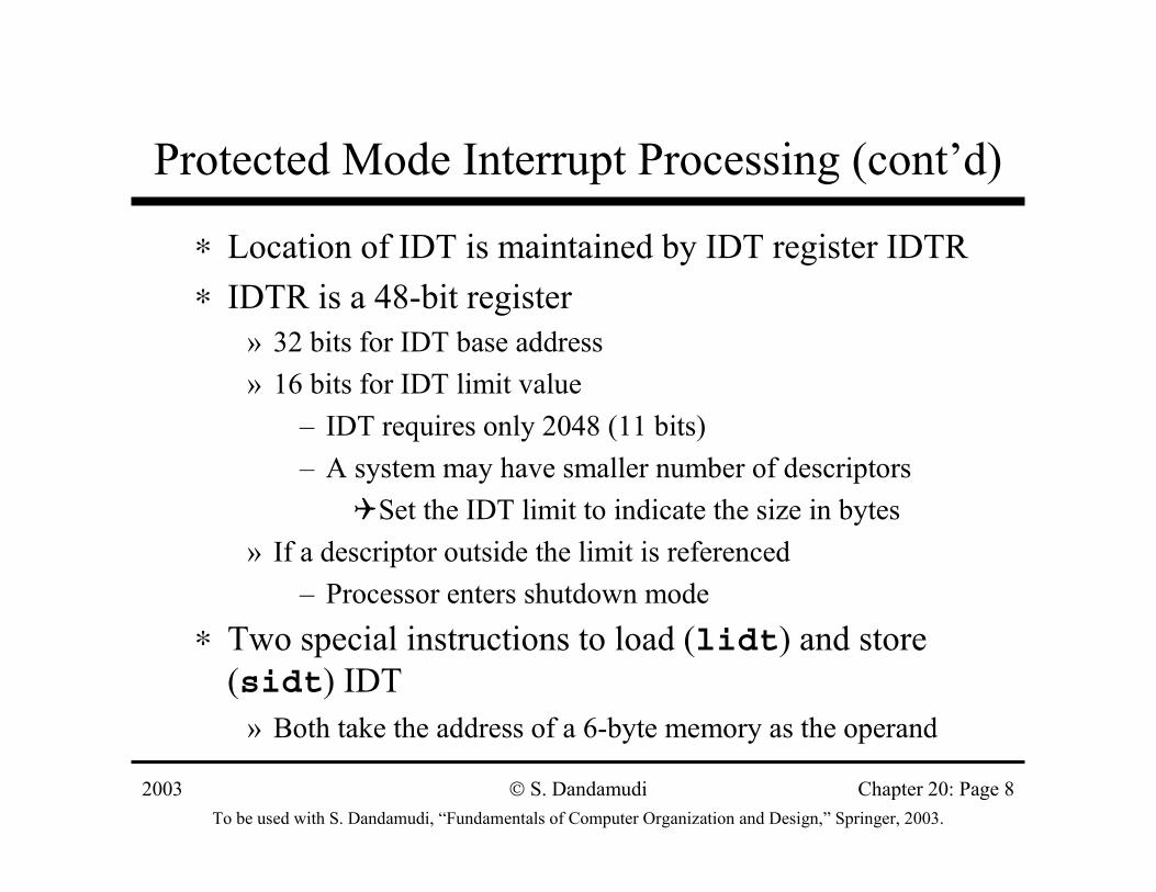
Protected Mode Interrupt Processing (cont’d)
∗ Location of IDT is maintained by IDT register IDTR∗ IDTR is a 48-bit register
» 32 bits for IDT base address» 16 bits for IDT limit value
– IDT requires only 2048 (11 bits)– A system may have smaller number of descriptors
Set the IDT limit to indicate the size in bytes» If a descriptor outside the limit is referenced
– Processor enters shutdown mode∗ Two special instructions to load (lidt) and store
(sidt) IDT» Both take the address of a 6-byte memory as the operand
2003To be used with S. Dandamudi, “Fundamentals of Computer Organization and Design,” Springer, 2003.
S. Dandamudi Chapter 20: Page 9
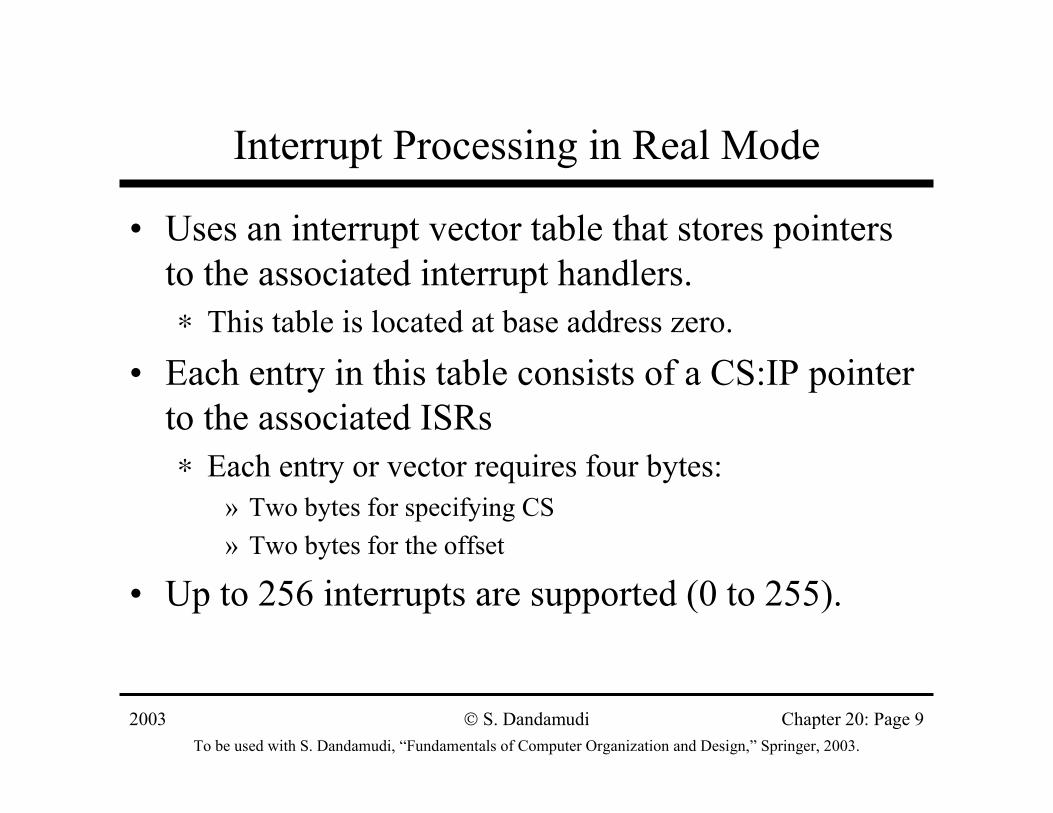
Interrupt Processing in Real Mode
• Uses an interrupt vector table that stores pointers to the associated interrupt handlers.∗ This table is located at base address zero.
• Each entry in this table consists of a CS:IP pointer to the associated ISRs∗ Each entry or vector requires four bytes:
» Two bytes for specifying CS» Two bytes for the offset
• Up to 256 interrupts are supported (0 to 255).
2003To be used with S. Dandamudi, “Fundamentals of Computer Organization and Design,” Springer, 2003.
S. Dandamudi Chapter 20: Page 10
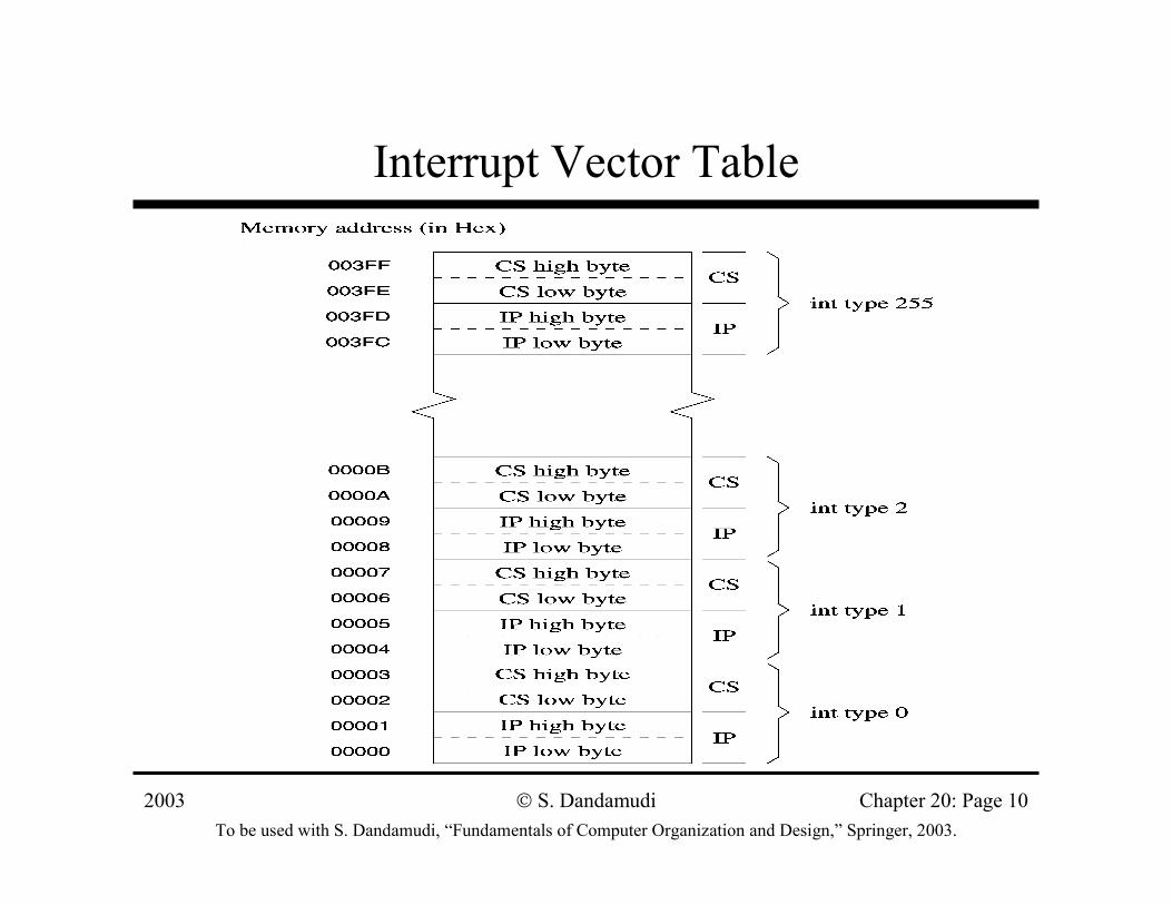
Interrupt Vector Table
2003To be used with S. Dandamudi, “Fundamentals of Computer Organization and Design,” Springer, 2003.
S. Dandamudi Chapter 20: Page 11
Interrupt Number to Vector Translation
• Interrupt numbers range from 0 to 255
• Interrupt number acts as an index into the interrupt vector table
• Since each vector takes 4 bytes, interrupt number is multiplied by 4 to get the corresponding ISR pointer
Example• For interrupt 2, the
memory address is2 ∗ 4 = 8H
• The first two bytes at 8H are taken as the offset value
• The next two bytes (i.e., at address AH) are used as the CS value
2003To be used with S. Dandamudi, “Fundamentals of Computer Organization and Design,” Springer, 2003.
S. Dandamudi Chapter 20: Page 12
A Typical ISR Structure
• Just like procedures, ISRs should end with a return statement to return control back
• The interrupt return (iret) is used of this purpose;save the registers used in the ISR
sti ;enable further interrupts
. . .
ISR body
. . .
;restore the saved registers
iret ;return to interrupted program
2003To be used with S. Dandamudi, “Fundamentals of Computer Organization and Design,” Springer, 2003.
S. Dandamudi Chapter 20: Page 13
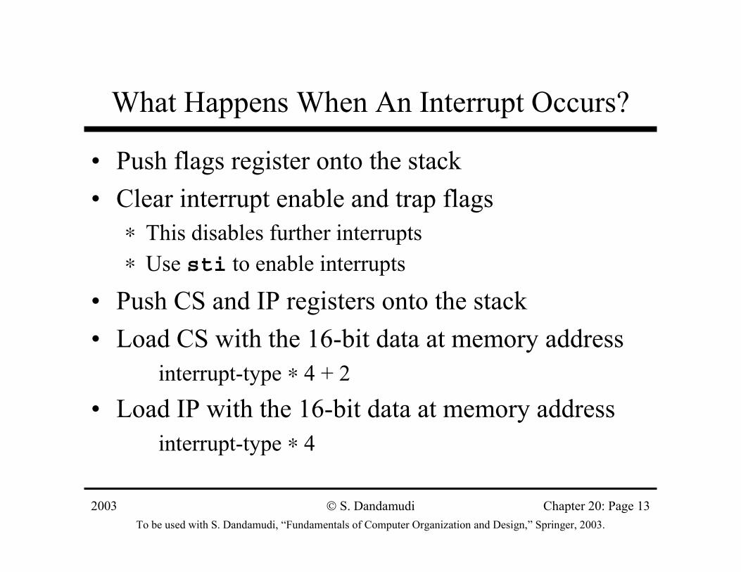
What Happens When An Interrupt Occurs?
• Push flags register onto the stack• Clear interrupt enable and trap flags
∗ This disables further interrupts∗ Use sti to enable interrupts
• Push CS and IP registers onto the stack• Load CS with the 16-bit data at memory address
interrupt-type ∗ 4 + 2 • Load IP with the 16-bit data at memory address
interrupt-type ∗ 4
2003To be used with S. Dandamudi, “Fundamentals of Computer Organization and Design,” Springer, 2003.
S. Dandamudi Chapter 20: Page 14
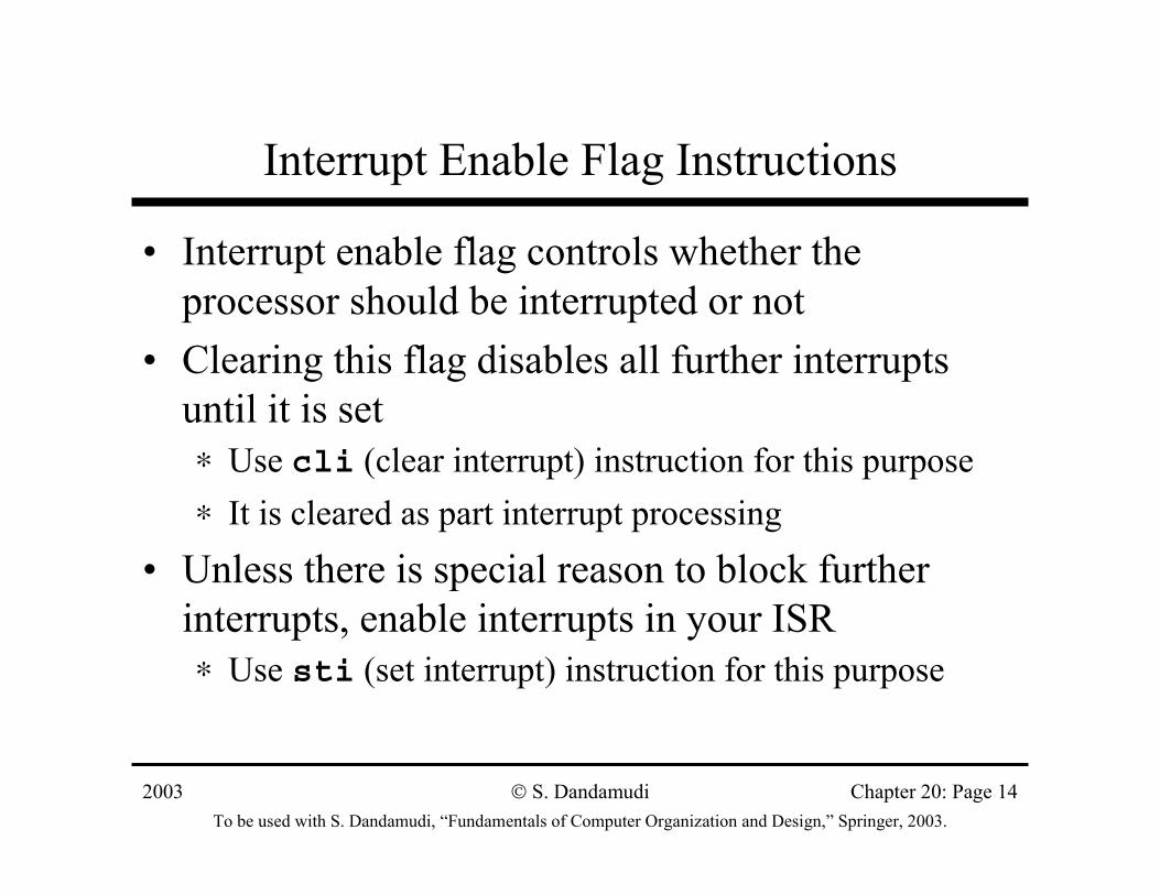
Interrupt Enable Flag Instructions
• Interrupt enable flag controls whether the processor should be interrupted or not
• Clearing this flag disables all further interrupts until it is set∗ Use cli (clear interrupt) instruction for this purpose∗ It is cleared as part interrupt processing
• Unless there is special reason to block further interrupts, enable interrupts in your ISR∗ Use sti (set interrupt) instruction for this purpose
2003To be used with S. Dandamudi, “Fundamentals of Computer Organization and Design,” Springer, 2003.
S. Dandamudi Chapter 20: Page 15
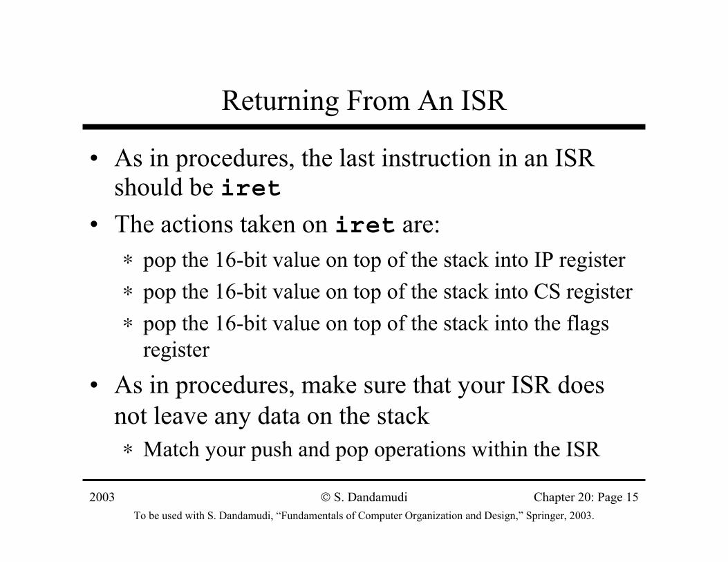
Returning From An ISR
• As in procedures, the last instruction in an ISR should be iret
• The actions taken on iret are:∗ pop the 16-bit value on top of the stack into IP register∗ pop the 16-bit value on top of the stack into CS register∗ pop the 16-bit value on top of the stack into the flags
register
• As in procedures, make sure that your ISR does not leave any data on the stack ∗ Match your push and pop operations within the ISR
2003To be used with S. Dandamudi, “Fundamentals of Computer Organization and Design,” Springer, 2003.
S. Dandamudi Chapter 20: Page 16
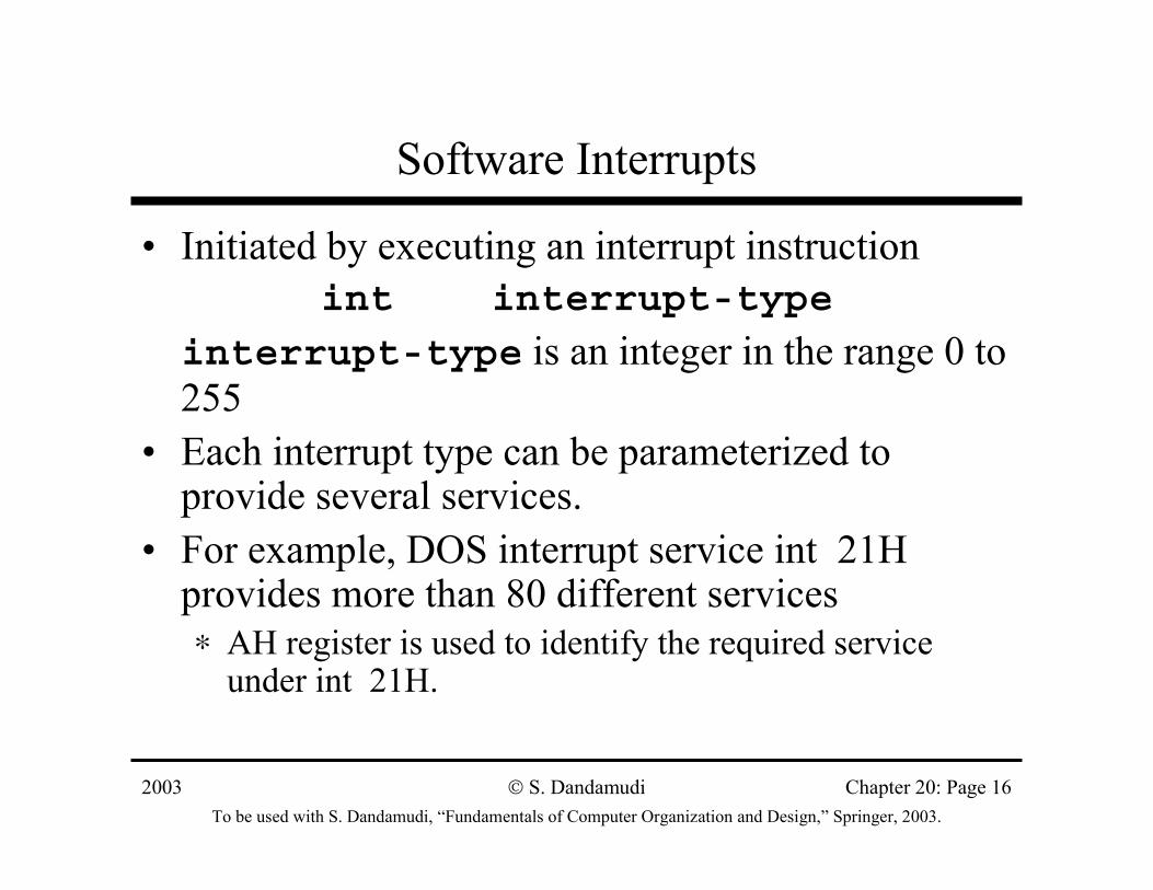
Software Interrupts
• Initiated by executing an interrupt instructionint interrupt-type
interrupt-type is an integer in the range 0 to 255
• Each interrupt type can be parameterized to provide several services.
• For example, DOS interrupt service int 21H provides more than 80 different services∗ AH register is used to identify the required service
under int 21H.
2003To be used with S. Dandamudi, “Fundamentals of Computer Organization and Design,” Springer, 2003.
S. Dandamudi Chapter 20: Page 17
Example DOS Service: Keyboard
• DOS provides several interrupt services to interact with the keyboard
• AH register should be loaded with the desired function under int 21H
• Seven functions are provided by DOS to read a character or get the status of the keyboard
» See Section 12.5.2 for details
• We look at one function to read a string of characters from the keyboard.
2003To be used with S. Dandamudi, “Fundamentals of Computer Organization and Design,” Springer, 2003.
S. Dandamudi Chapter 20: Page 18
A DOS Keyboard Function
• Function 0AH --- Buffered Keyboard Input Inputs: AH = 0AH
DS:DX = pointer to the input buffer(first byte should be buffer size)
Returns: character string in the input buffer
• Input string is terminated by CR• Input string starts at the third byte of the buffer• Second byte gives the actual number of characters
read (excluding the CR)
2003To be used with S. Dandamudi, “Fundamentals of Computer Organization and Design,” Springer, 2003.
S. Dandamudi Chapter 20: Page 19
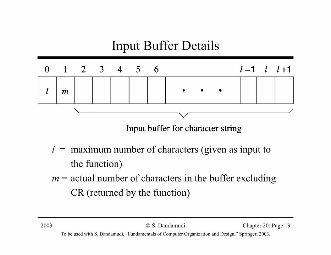
Input Buffer Details
l = maximum number of characters (given as input to the function)
m = actual number of characters in the buffer excludingCR (returned by the function)
2003To be used with S. Dandamudi, “Fundamentals of Computer Organization and Design,” Springer, 2003.
S. Dandamudi Chapter 20: Page 20
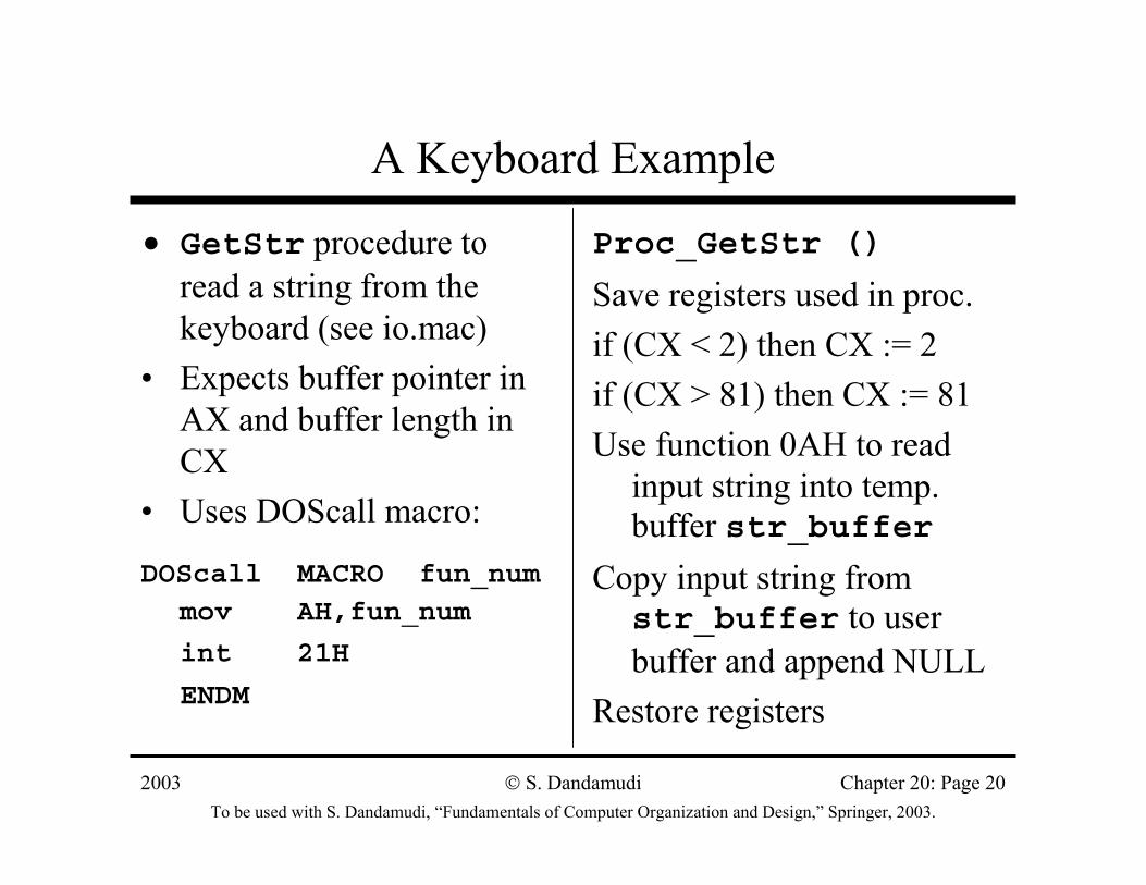
A Keyboard Example
• GetStr procedure to read a string from the keyboard (see io.mac)
• Expects buffer pointer in AX and buffer length in CX
• Uses DOScall macro:
DOScall MACRO fun_nummov AH,fun_num
int 21H
ENDM
Proc_GetStr ()
Save registers used in proc.if (CX < 2) then CX := 2if (CX > 81) then CX := 81Use function 0AH to read
input string into temp. buffer str_buffer
Copy input string from str_buffer to user buffer and append NULL
Restore registers
2003To be used with S. Dandamudi, “Fundamentals of Computer Organization and Design,” Springer, 2003.
S. Dandamudi Chapter 20: Page 21
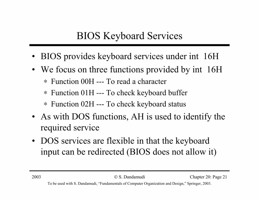
BIOS Keyboard Services
• BIOS provides keyboard services under int 16H• We focus on three functions provided by int 16H
∗ Function 00H --- To read a character∗ Function 01H --- To check keyboard buffer∗ Function 02H --- To check keyboard status
• As with DOS functions, AH is used to identify the required service
• DOS services are flexible in that the keyboard input can be redirected (BIOS does not allow it)
2003To be used with S. Dandamudi, “Fundamentals of Computer Organization and Design,” Springer, 2003.
S. Dandamudi Chapter 20: Page 22
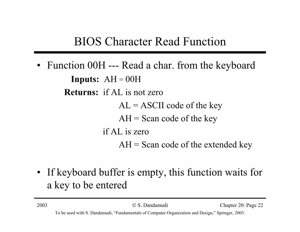
BIOS Character Read Function
• Function 00H --- Read a char. from the keyboardInputs: AH = 00H
Returns: if AL is not zeroAL = ASCII code of the keyAH = Scan code of the key
if AL is zeroAH = Scan code of the extended key
• If keyboard buffer is empty, this function waits for a key to be entered
2003To be used with S. Dandamudi, “Fundamentals of Computer Organization and Design,” Springer, 2003.
S. Dandamudi Chapter 20: Page 23
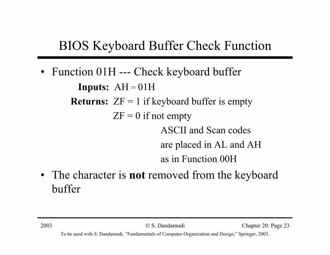
BIOS Keyboard Buffer Check Function
• Function 01H --- Check keyboard bufferInputs: AH = 01H
Returns: ZF = 1 if keyboard buffer is emptyZF = 0 if not empty
ASCII and Scan codes are placed in AL and AH as in Function 00H
• The character is not removed from the keyboard buffer
2003To be used with S. Dandamudi, “Fundamentals of Computer Organization and Design,” Springer, 2003.
S. Dandamudi Chapter 20: Page 24
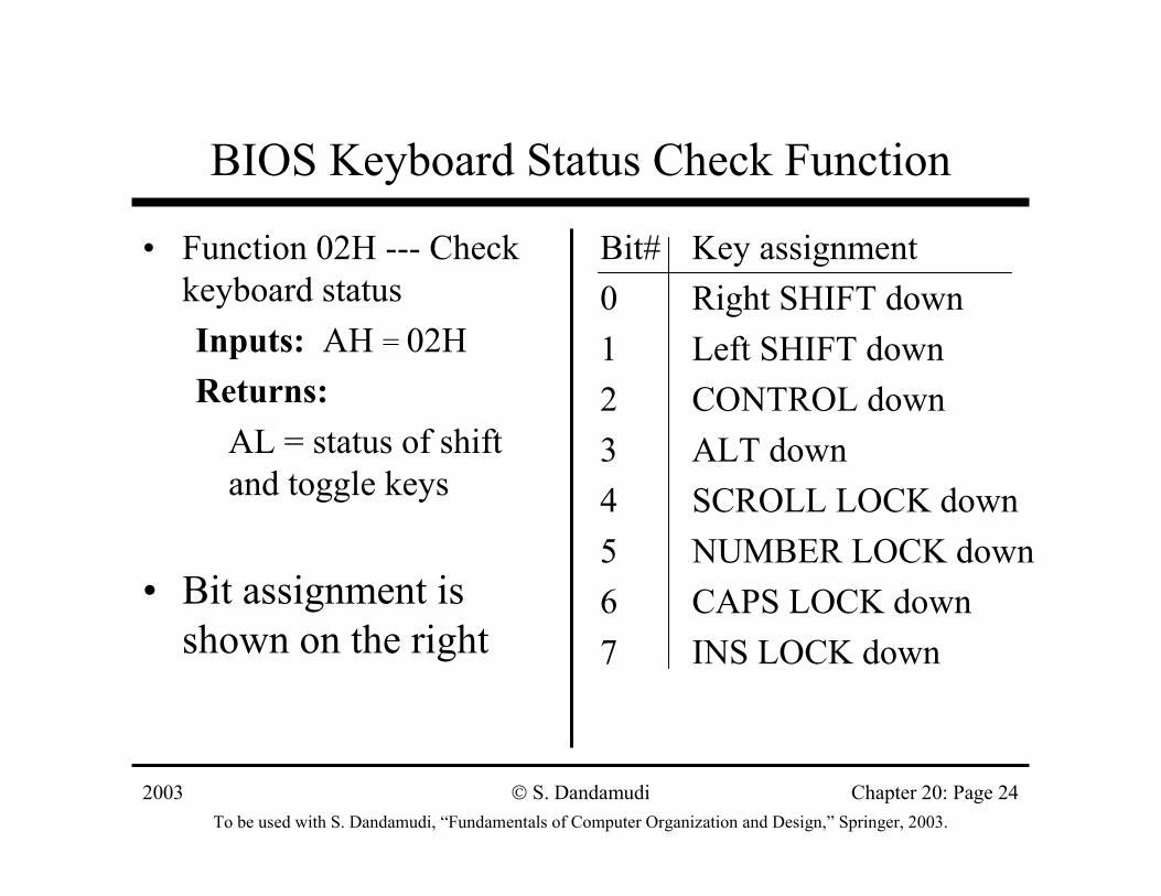
BIOS Keyboard Status Check Function
• Function 02H --- Check keyboard statusInputs: AH = 02HReturns:
AL = status of shift and toggle keys
• Bit assignment is shown on the right
Bit# Key assignment0 Right SHIFT down 1 Left SHIFT down2 CONTROL down3 ALT down4 SCROLL LOCK down5 NUMBER LOCK down6 CAPS LOCK down7 INS LOCK down
2003To be used with S. Dandamudi, “Fundamentals of Computer Organization and Design,” Springer, 2003.
S. Dandamudi Chapter 20: Page 25
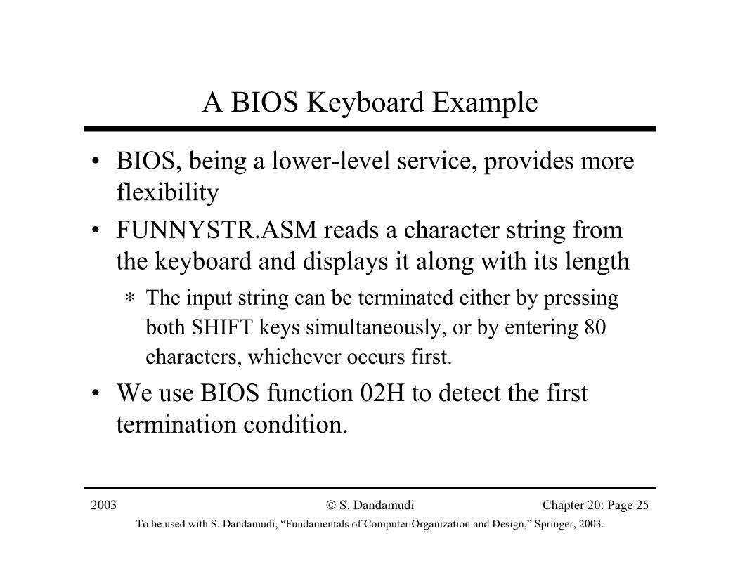
A BIOS Keyboard Example
• BIOS, being a lower-level service, provides more flexibility
• FUNNYSTR.ASM reads a character string from the keyboard and displays it along with its length∗ The input string can be terminated either by pressing
both SHIFT keys simultaneously, or by entering 80 characters, whichever occurs first.
• We use BIOS function 02H to detect the first termination condition.
2003To be used with S. Dandamudi, “Fundamentals of Computer Organization and Design,” Springer, 2003.
S. Dandamudi Chapter 20: Page 26
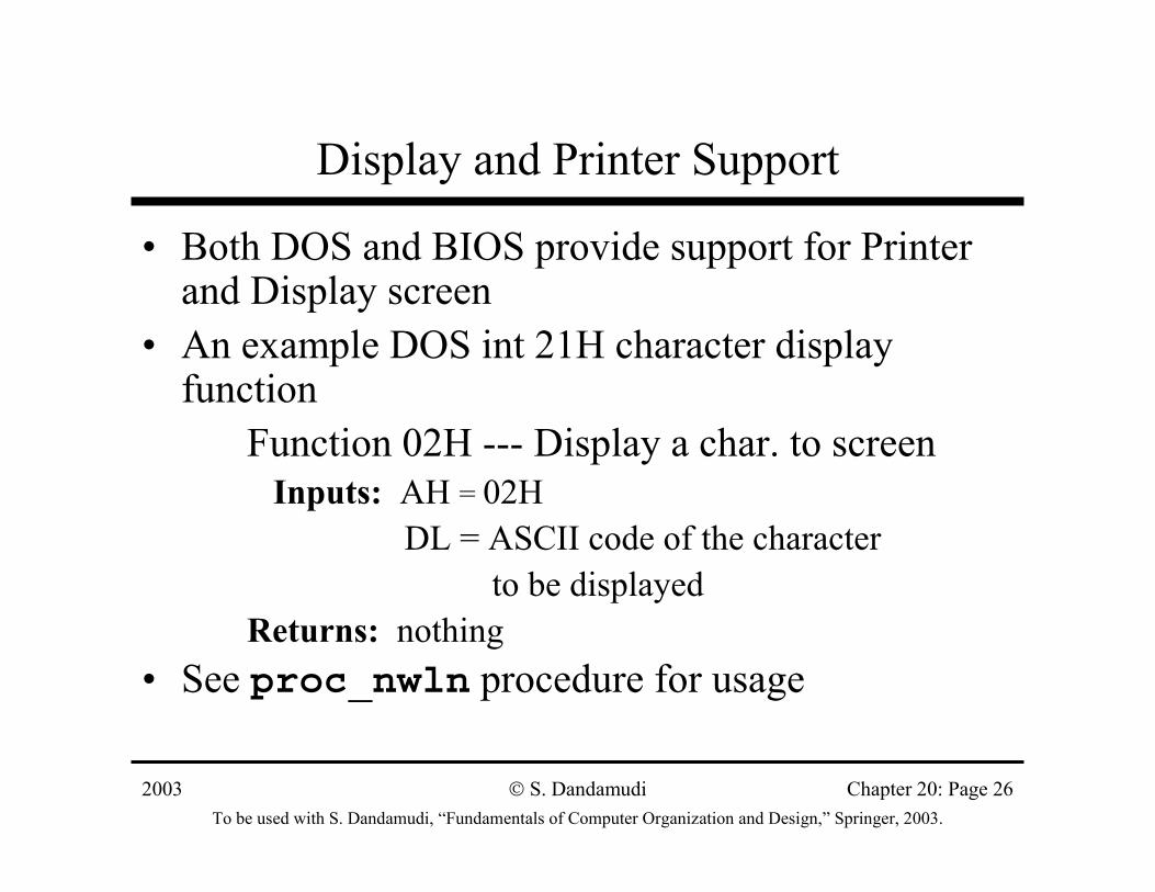
Display and Printer Support
• Both DOS and BIOS provide support for Printer and Display screen
• An example DOS int 21H character display function
Function 02H --- Display a char. to screenInputs: AH = 02H
DL = ASCII code of the character to be displayed
Returns: nothing• See proc_nwln procedure for usage
2003To be used with S. Dandamudi, “Fundamentals of Computer Organization and Design,” Springer, 2003.
S. Dandamudi Chapter 20: Page 27
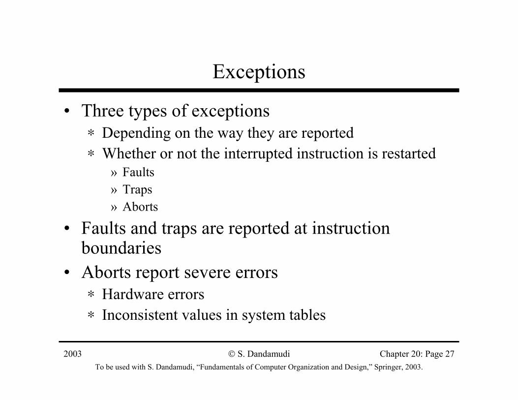
Exceptions
• Three types of exceptions∗ Depending on the way they are reported∗ Whether or not the interrupted instruction is restarted
» Faults» Traps» Aborts
• Faults and traps are reported at instruction boundaries
• Aborts report severe errors∗ Hardware errors∗ Inconsistent values in system tables
2003To be used with S. Dandamudi, “Fundamentals of Computer Organization and Design,” Springer, 2003.
S. Dandamudi Chapter 20: Page 28
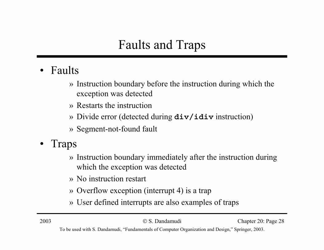
Faults and Traps
• Faults» Instruction boundary before the instruction during which the
exception was detected» Restarts the instruction» Divide error (detected during div/idiv instruction)» Segment-not-found fault
• Traps» Instruction boundary immediately after the instruction during
which the exception was detected» No instruction restart» Overflow exception (interrupt 4) is a trap» User defined interrupts are also examples of traps
2003To be used with S. Dandamudi, “Fundamentals of Computer Organization and Design,” Springer, 2003.
S. Dandamudi Chapter 20: Page 29
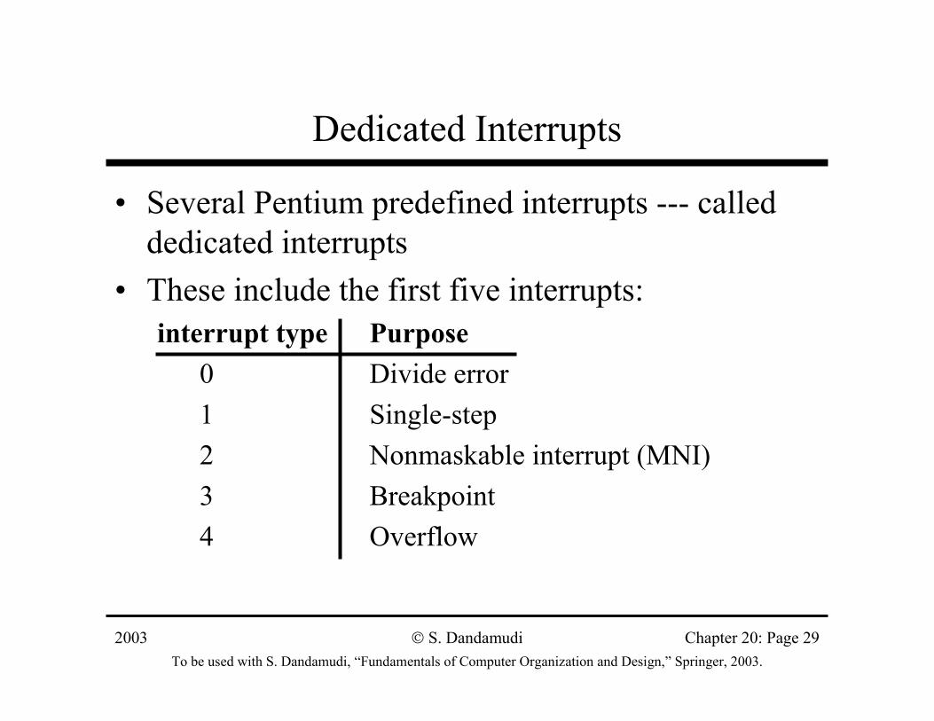
Dedicated Interrupts
• Several Pentium predefined interrupts --- called dedicated interrupts
• These include the first five interrupts:interrupt type Purpose
0 Divide error1 Single-step2 Nonmaskable interrupt (MNI)3 Breakpoint4 Overflow
2003To be used with S. Dandamudi, “Fundamentals of Computer Organization and Design,” Springer, 2003.
S. Dandamudi Chapter 20: Page 30
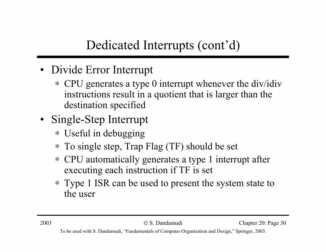
Dedicated Interrupts (cont’d)
• Divide Error Interrupt∗ CPU generates a type 0 interrupt whenever the div/idiv
instructions result in a quotient that is larger than the destination specified
• Single-Step Interrupt∗ Useful in debugging∗ To single step, Trap Flag (TF) should be set∗ CPU automatically generates a type 1 interrupt after
executing each instruction if TF is set∗ Type 1 ISR can be used to present the system state to
the user
2003To be used with S. Dandamudi, “Fundamentals of Computer Organization and Design,” Springer, 2003.
S. Dandamudi Chapter 20: Page 31
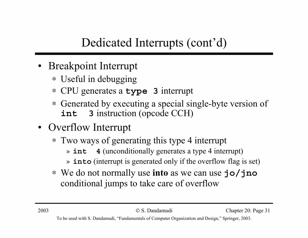
Dedicated Interrupts (cont’d)
• Breakpoint Interrupt∗ Useful in debugging ∗ CPU generates a type 3 interrupt ∗ Generated by executing a special single-byte version of int 3 instruction (opcode CCH)
• Overflow Interrupt∗ Two ways of generating this type 4 interrupt
» int 4 (unconditionally generates a type 4 interrupt)» into (interrupt is generated only if the overflow flag is set)
∗ We do not normally use into as we can use jo/jnoconditional jumps to take care of overflow
2003To be used with S. Dandamudi, “Fundamentals of Computer Organization and Design,” Springer, 2003.
S. Dandamudi Chapter 20: Page 32
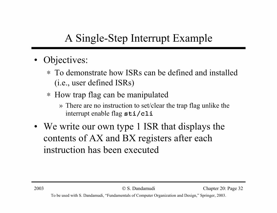
A Single-Step Interrupt Example
• Objectives:∗ To demonstrate how ISRs can be defined and installed
(i.e., user defined ISRs)∗ How trap flag can be manipulated
» There are no instruction to set/clear the trap flag unlike the interrupt enable flag sti/cli
• We write our own type 1 ISR that displays the contents of AX and BX registers after each instruction has been executed
2003To be used with S. Dandamudi, “Fundamentals of Computer Organization and Design,” Springer, 2003.
S. Dandamudi Chapter 20: Page 33
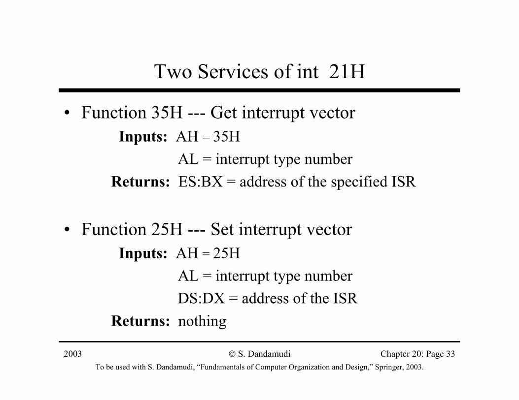
Two Services of int 21H
• Function 35H --- Get interrupt vector Inputs: AH = 35H
AL = interrupt type numberReturns: ES:BX = address of the specified ISR
• Function 25H --- Set interrupt vector Inputs: AH = 25H
AL = interrupt type numberDS:DX = address of the ISR
Returns: nothing
2003To be used with S. Dandamudi, “Fundamentals of Computer Organization and Design,” Springer, 2003.
S. Dandamudi Chapter 20: Page 34
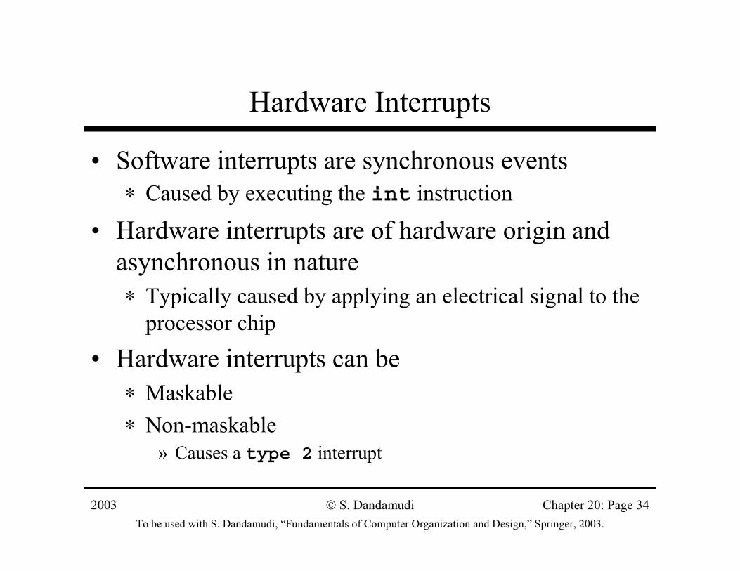
Hardware Interrupts
• Software interrupts are synchronous events ∗ Caused by executing the int instruction
• Hardware interrupts are of hardware origin and asynchronous in nature∗ Typically caused by applying an electrical signal to the
processor chip
• Hardware interrupts can be ∗ Maskable∗ Non-maskable
» Causes a type 2 interrupt
2003To be used with S. Dandamudi, “Fundamentals of Computer Organization and Design,” Springer, 2003.
S. Dandamudi Chapter 20: Page 35
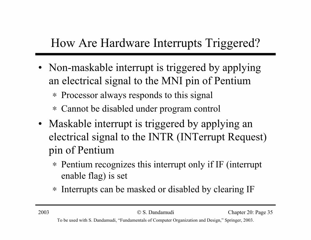
How Are Hardware Interrupts Triggered?
• Non-maskable interrupt is triggered by applying an electrical signal to the MNI pin of Pentium∗ Processor always responds to this signal∗ Cannot be disabled under program control
• Maskable interrupt is triggered by applying an electrical signal to the INTR (INTerrupt Request) pin of Pentium∗ Pentium recognizes this interrupt only if IF (interrupt
enable flag) is set∗ Interrupts can be masked or disabled by clearing IF
2003To be used with S. Dandamudi, “Fundamentals of Computer Organization and Design,” Springer, 2003.
S. Dandamudi Chapter 20: Page 36
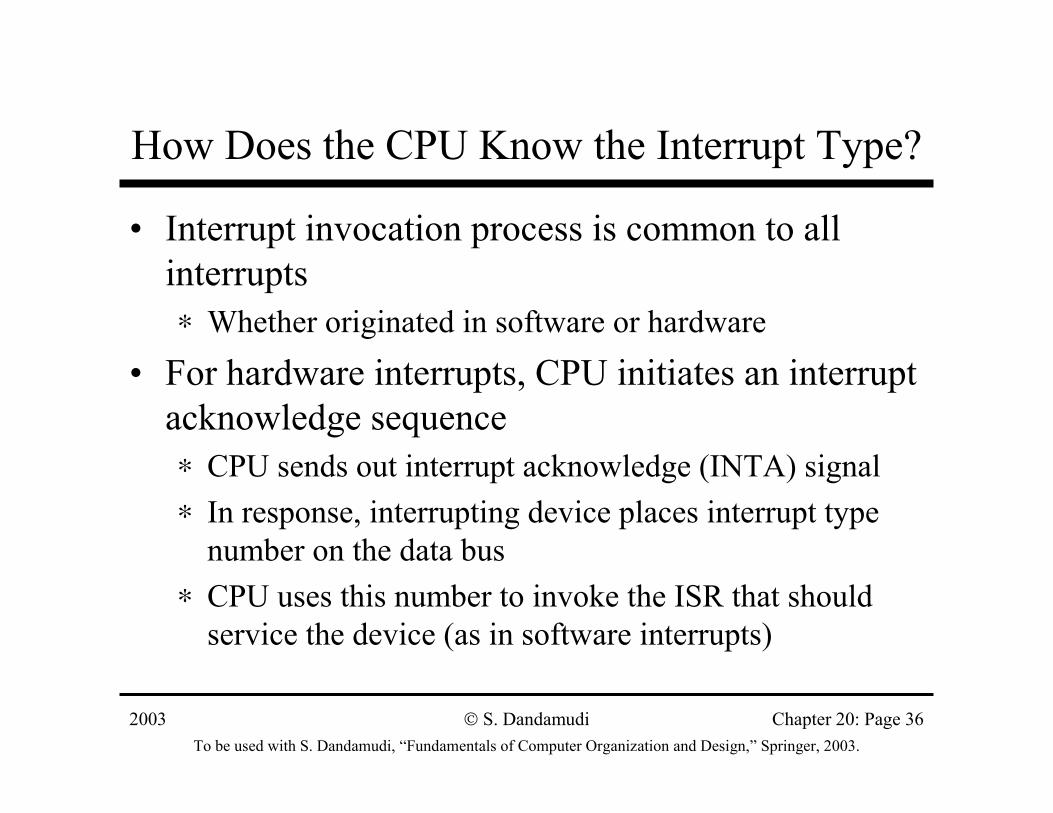
How Does the CPU Know the Interrupt Type?
• Interrupt invocation process is common to all interrupts∗ Whether originated in software or hardware
• For hardware interrupts, CPU initiates an interrupt acknowledge sequence∗ CPU sends out interrupt acknowledge (INTA) signal∗ In response, interrupting device places interrupt type
number on the data bus∗ CPU uses this number to invoke the ISR that should
service the device (as in software interrupts)
2003To be used with S. Dandamudi, “Fundamentals of Computer Organization and Design,” Springer, 2003.
S. Dandamudi Chapter 20: Page 37
How can More Than One Device Interrupt?
• Processor has only one INTR pin to receive interrupt signal
• Typical system has more than one device that can interrupt --- keyboard, hard disk, floppy, etc.
• Use a special chip to prioritize the interrupts and forward only one interrupt to the CPU
• 8259 Programmable Interrupt Controller chip performs this function (more details later)
2003To be used with S. Dandamudi, “Fundamentals of Computer Organization and Design,” Springer, 2003.
S. Dandamudi Chapter 20: Page 38
Direct Control of I/O Devices
• Two ways of mapping I/O ports:∗ Memory-mapped I/O (e.g., MIPS)
» I/O port is treated as a memory address (I/O port is mapped to a location in memory address space (MAS))
» Accessing an I/O port (read/write) is similar to accessing a memory location (all memory access instructions can be used)
∗ Isolated I/O (e.g., Pentium)» I/O address space is separate from the memory address space
– leaves the complete MAS for memory» Separate I/O instructions and I/O signals are needed » Can’t use memory access instructions» Can also use memory-mapped I/O and use all memory access
instructions
2003To be used with S. Dandamudi, “Fundamentals of Computer Organization and Design,” Springer, 2003.
S. Dandamudi Chapter 20: Page 39
Pentium I/O Address Space
• Pentium provides 64 KB of I/O address space∗ Can be used for 8-, 16-, and 32-bit I/O ports
• Combination cannot exceed the total I/O space∗ 64K 8-bit I/O ports
» Used for 8-bit devices, which transfer 8-bit data» Can be located anywhere in the I/O space
∗ 32K 16-bit I/O ports (used for 16-bit devices)» 16-bit ports should be aligned to an even address
∗ 16K 32-bit I/O ports (used for 32-bit devices)» Should be aligned to addresses that are multiples of four» Pentium supports unaligned ports, but with performance penalty
∗ A combination of these for a total of 64 KB
2003To be used with S. Dandamudi, “Fundamentals of Computer Organization and Design,” Springer, 2003.
S. Dandamudi Chapter 20: Page 40
Pentium I/O Instructions
• Pentium provides two types of I/O instructions:∗ Register I/O instructions
» Used to transfer data between a register (accumulator) and an I/O port
» in −−−− to read from an I/O port» out −−−− to write to an I/O port
∗ Block I/O instructions» Used to transfer a block of data between memory and an I/O
port» ins −−−− to read from an I/O port» outs −−−− to write to an I/O port
2003To be used with S. Dandamudi, “Fundamentals of Computer Organization and Design,” Springer, 2003.
S. Dandamudi Chapter 20: Page 41
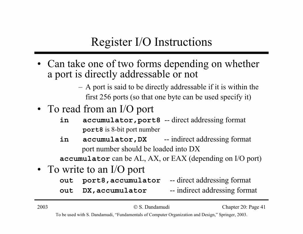
Register I/O Instructions
• Can take one of two forms depending on whether a port is directly addressable or not
– A port is said to be directly addressable if it is within the first 256 ports (so that one byte can be used specify it)
• To read from an I/O portin accumulator,port8 -- direct addressing format
port8 is 8-bit port numberin accumulator,DX -- indirect addressing format
port number should be loaded into DXaccumulator can be AL, AX, or EAX (depending on I/O port)
• To write to an I/O portout port8,accumulator -- direct addressing formatout DX,accumulator -- indirect addressing format
2003To be used with S. Dandamudi, “Fundamentals of Computer Organization and Design,” Springer, 2003.
S. Dandamudi Chapter 20: Page 42
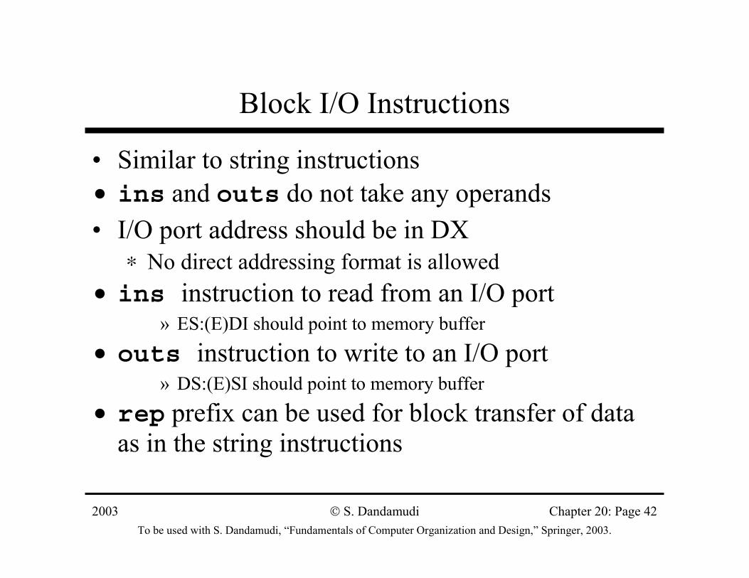
Block I/O Instructions
• Similar to string instructions• ins and outs do not take any operands• I/O port address should be in DX
∗ No direct addressing format is allowed• ins instruction to read from an I/O port
» ES:(E)DI should point to memory buffer
• outs instruction to write to an I/O port» DS:(E)SI should point to memory buffer
• rep prefix can be used for block transfer of data as in the string instructions
2003To be used with S. Dandamudi, “Fundamentals of Computer Organization and Design,” Springer, 2003.
S. Dandamudi Chapter 20: Page 43
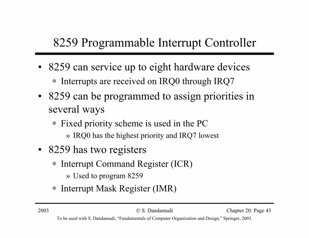
8259 Programmable Interrupt Controller
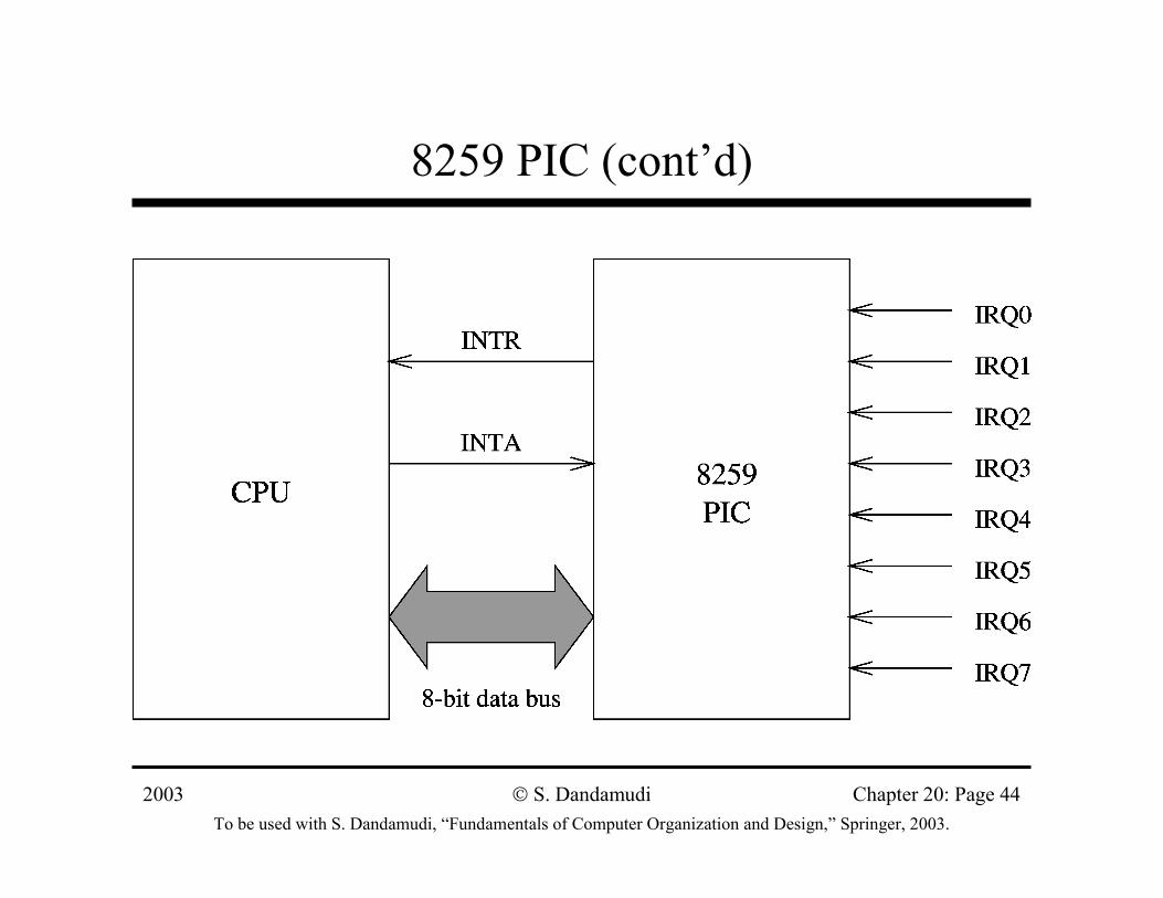
• 8259 can service up to eight hardware devices∗ Interrupts are received on IRQ0 through IRQ7
• 8259 can be programmed to assign priorities in several ways∗ Fixed priority scheme is used in the PC
» IRQ0 has the highest priority and IRQ7 lowest
• 8259 has two registers∗ Interrupt Command Register (ICR)
» Used to program 8259
∗ Interrupt Mask Register (IMR)
2003To be used with S. Dandamudi, “Fundamentals of Computer Organization and Design,” Springer, 2003.
S. Dandamudi Chapter 20: Page 44
8259 PIC (cont’d)
2003To be used with S. Dandamudi, “Fundamentals of Computer Organization and Design,” Springer, 2003.
S. Dandamudi Chapter 20: Page 45
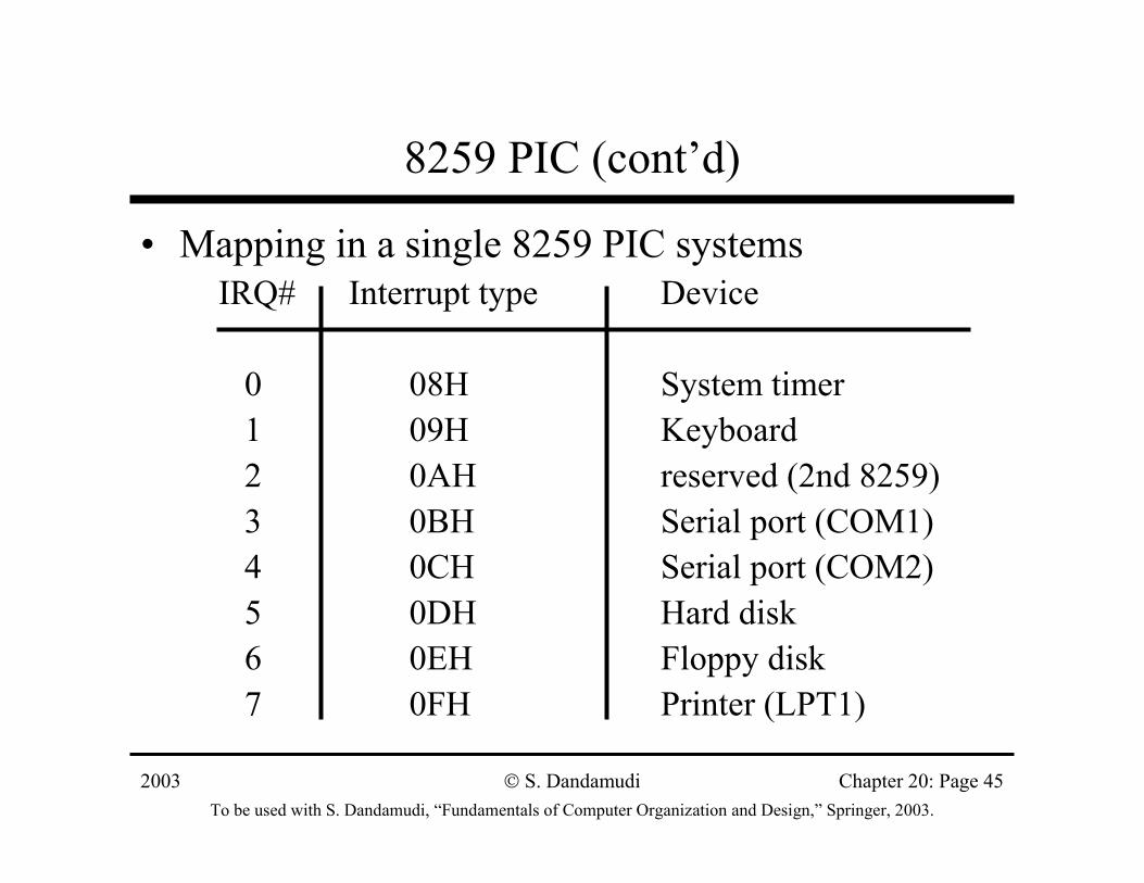
8259 PIC (cont’d)
• Mapping in a single 8259 PIC systemsIRQ# Interrupt type Device
0 08H System timer1 09H Keyboard2 0AH reserved (2nd 8259)3 0BH Serial port (COM1)4 0CH Serial port (COM2)5 0DH Hard disk6 0EH Floppy disk7 0FH Printer (LPT1)
2003To be used with S. Dandamudi, “Fundamentals of Computer Organization and Design,” Springer, 2003.
S. Dandamudi Chapter 20: Page 46
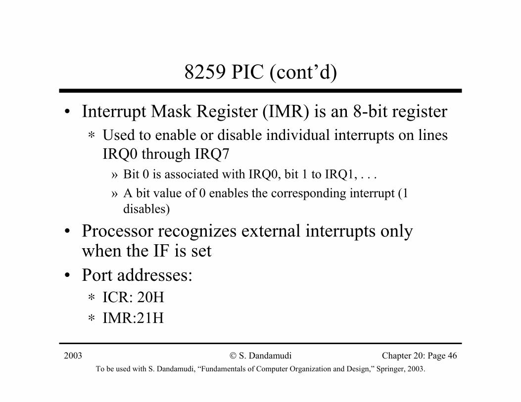
8259 PIC (cont’d)
• Interrupt Mask Register (IMR) is an 8-bit register∗ Used to enable or disable individual interrupts on lines
IRQ0 through IRQ7» Bit 0 is associated with IRQ0, bit 1 to IRQ1, . . .» A bit value of 0 enables the corresponding interrupt (1
disables)
• Processor recognizes external interrupts only when the IF is set
• Port addresses:∗ ICR: 20H∗ IMR:21H
2003To be used with S. Dandamudi, “Fundamentals of Computer Organization and Design,” Springer, 2003.
S. Dandamudi Chapter 20: Page 47
8259 PIC (cont’d)
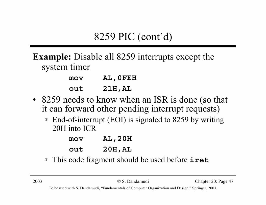
Example: Disable all 8259 interrupts except the system timer
mov AL,0FEH
out 21H,AL
• 8259 needs to know when an ISR is done (so that it can forward other pending interrupt requests)∗ End-of-interrupt (EOI) is signaled to 8259 by writing
20H into ICRmov AL,20H
out 20H,AL
∗ This code fragment should be used before iret
2003To be used with S. Dandamudi, “Fundamentals of Computer Organization and Design,” Springer, 2003.
S. Dandamudi Chapter 20: Page 48
8255 Programmable Peripheral Interface Chip
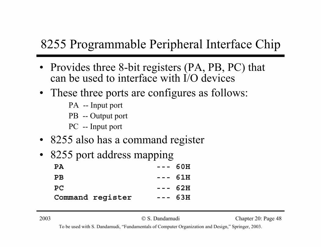
• Provides three 8-bit registers (PA, PB, PC) that can be used to interface with I/O devices
• These three ports are configures as follows:PA -- Input portPB -- Output portPC -- Input port
• 8255 also has a command register• 8255 port address mapping
PA --- 60H
PB --- 61H
PC --- 62HCommand register --- 63H
2003To be used with S. Dandamudi, “Fundamentals of Computer Organization and Design,” Springer, 2003.
S. Dandamudi Chapter 20: Page 49
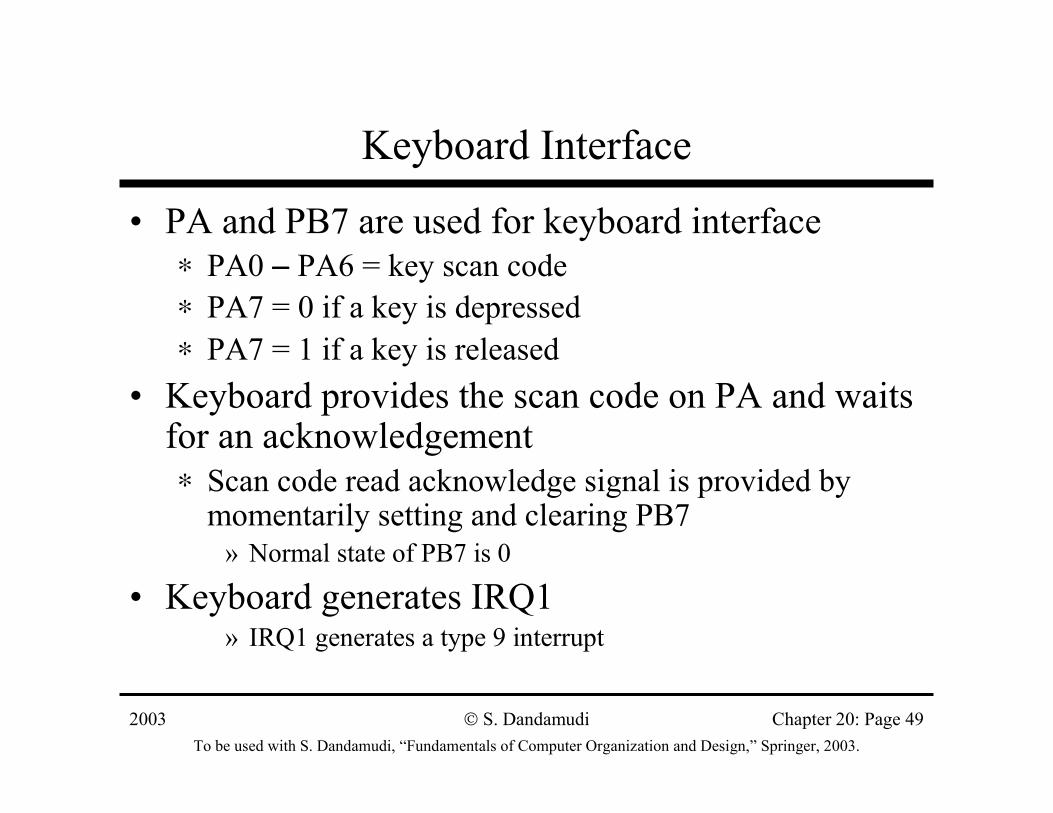
Keyboard Interface
• PA and PB7 are used for keyboard interface∗ PA0 −−−− PA6 = key scan code∗ PA7 = 0 if a key is depressed ∗ PA7 = 1 if a key is released
• Keyboard provides the scan code on PA and waits for an acknowledgement∗ Scan code read acknowledge signal is provided by
momentarily setting and clearing PB7» Normal state of PB7 is 0
• Keyboard generates IRQ1 » IRQ1 generates a type 9 interrupt
2003To be used with S. Dandamudi, “Fundamentals of Computer Organization and Design,” Springer, 2003.
S. Dandamudi Chapter 20: Page 50
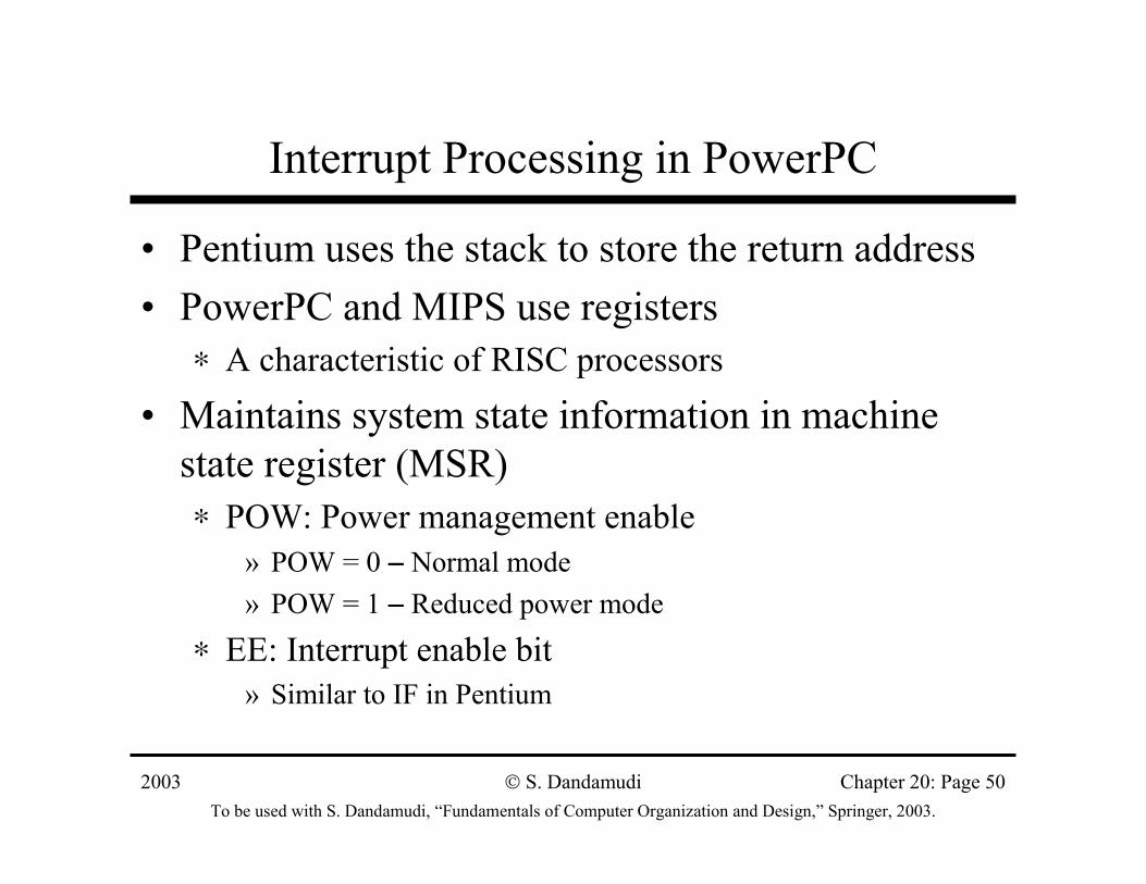
Interrupt Processing in PowerPC
• Pentium uses the stack to store the return address• PowerPC and MIPS use registers
∗ A characteristic of RISC processors
• Maintains system state information in machine state register (MSR)∗ POW: Power management enable
» POW = 0 −−−− Normal mode» POW = 1 −−−− Reduced power mode
∗ EE: Interrupt enable bit» Similar to IF in Pentium
2003To be used with S. Dandamudi, “Fundamentals of Computer Organization and Design,” Springer, 2003.
S. Dandamudi Chapter 20: Page 51
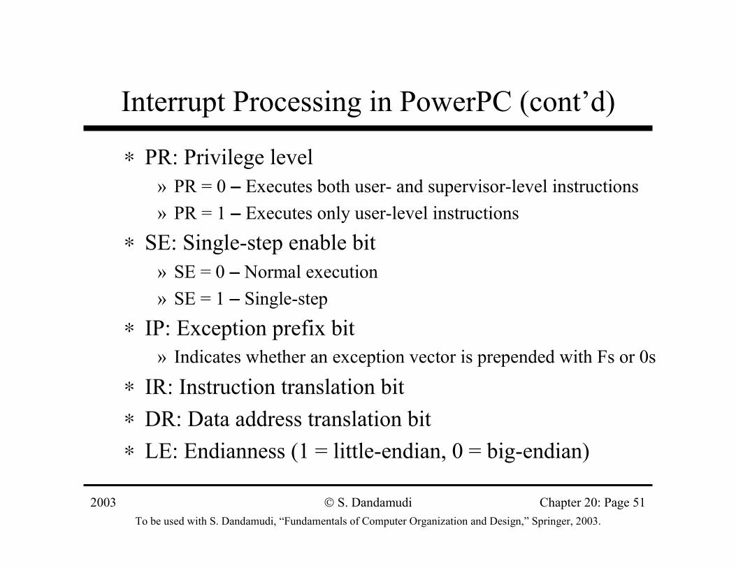
Interrupt Processing in PowerPC (cont’d)
∗ PR: Privilege level» PR = 0 −−−− Executes both user- and supervisor-level instructions» PR = 1 −−−− Executes only user-level instructions
∗ SE: Single-step enable bit» SE = 0 −−−− Normal execution» SE = 1 −−−− Single-step
∗ IP: Exception prefix bit» Indicates whether an exception vector is prepended with Fs or 0s
∗ IR: Instruction translation bit∗ DR: Data address translation bit∗ LE: Endianness (1 = little-endian, 0 = big-endian)
2003To be used with S. Dandamudi, “Fundamentals of Computer Organization and Design,” Springer, 2003.
S. Dandamudi Chapter 20: Page 52
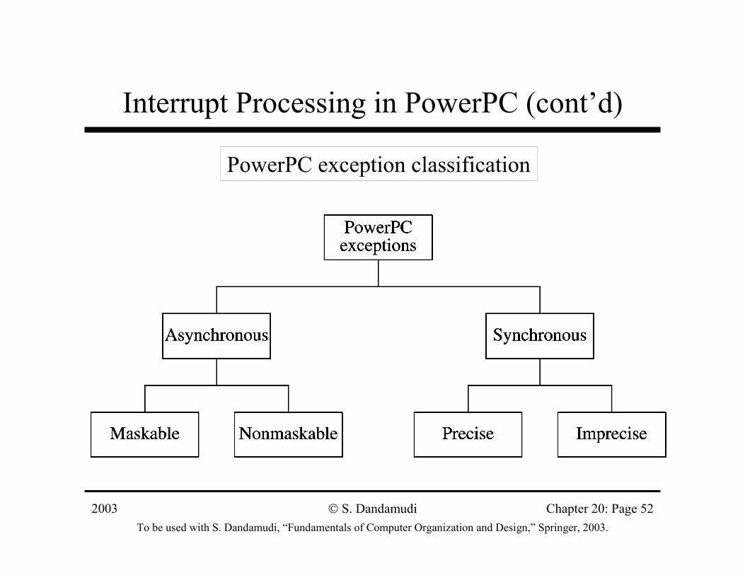
Interrupt Processing in PowerPC (cont’d)
PowerPC exception classification
2003To be used with S. Dandamudi, “Fundamentals of Computer Organization and Design,” Springer, 2003.
S. Dandamudi Chapter 20: Page 53
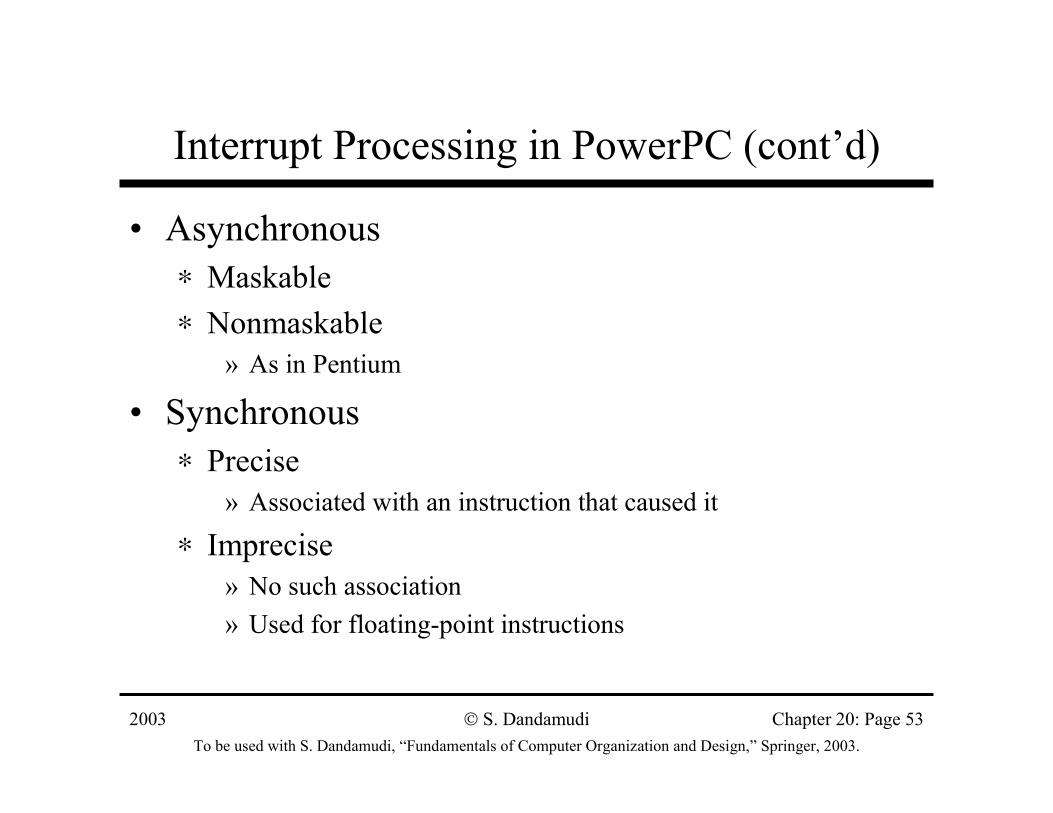
Interrupt Processing in PowerPC (cont’d)
• Asynchronous∗ Maskable∗ Nonmaskable
» As in Pentium
• Synchronous∗ Precise
» Associated with an instruction that caused it
∗ Imprecise» No such association» Used for floating-point instructions
2003To be used with S. Dandamudi, “Fundamentals of Computer Organization and Design,” Springer, 2003.
S. Dandamudi Chapter 20: Page 54
Interrupt Processing in PowerPC (cont’d)
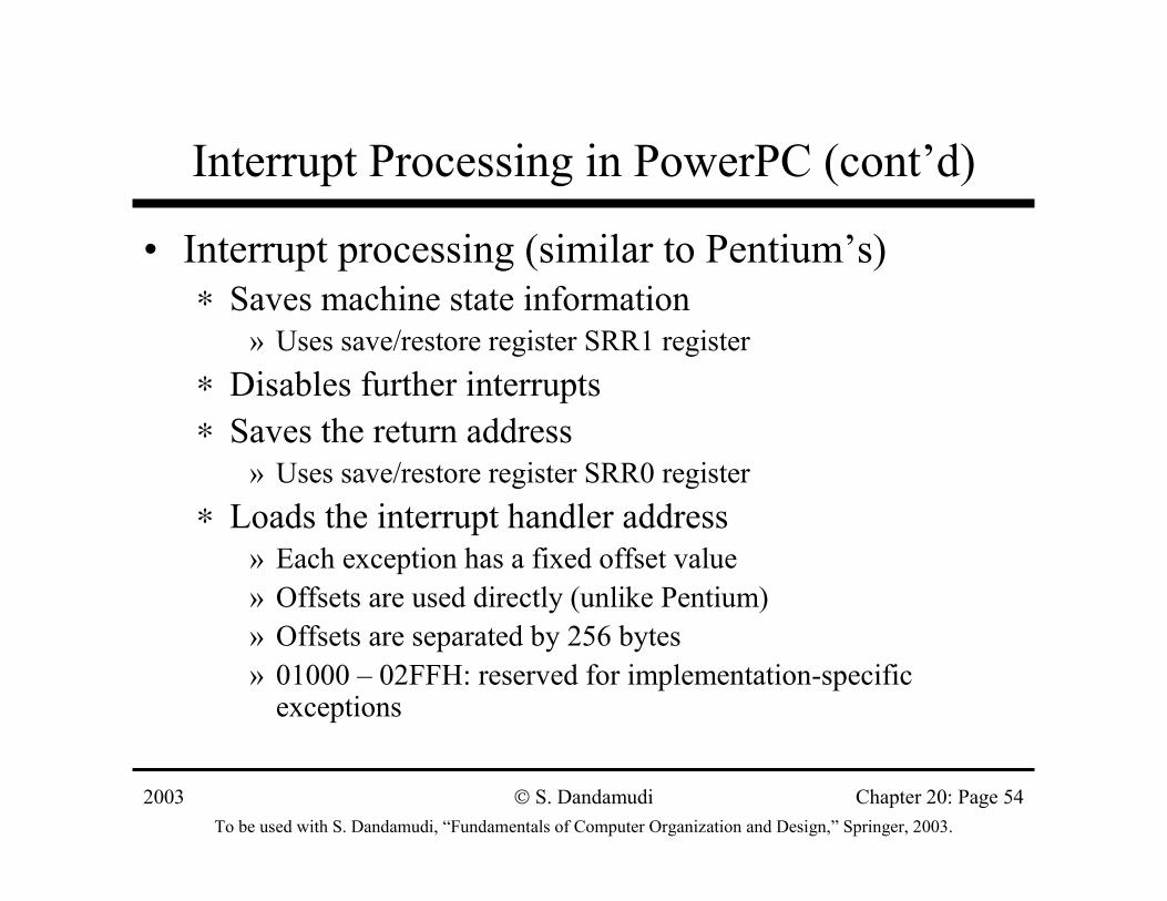
• Interrupt processing (similar to Pentium’s)∗ Saves machine state information
» Uses save/restore register SRR1 register∗ Disables further interrupts∗ Saves the return address
» Uses save/restore register SRR0 register∗ Loads the interrupt handler address
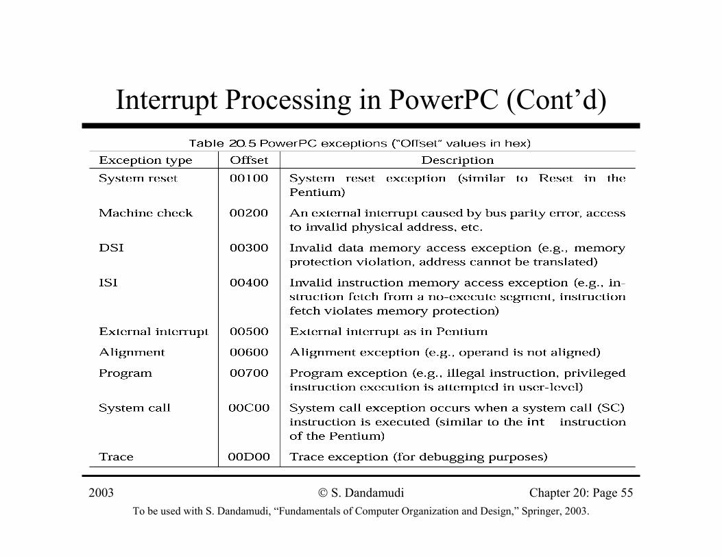
» Each exception has a fixed offset value» Offsets are used directly (unlike Pentium)» Offsets are separated by 256 bytes» 01000 – 02FFH: reserved for implementation-specific
exceptions
2003To be used with S. Dandamudi, “Fundamentals of Computer Organization and Design,” Springer, 2003.
S. Dandamudi Chapter 20: Page 55
Interrupt Processing in PowerPC (Cont’d)
2003To be used with S. Dandamudi, “Fundamentals of Computer Organization and Design,” Springer, 2003.
S. Dandamudi Chapter 20: Page 56
Interrupt Processing in PowerPC (Cont’d)
• If IP = 1, leading prefixes are Fs• Example:
∗ IP = 1: 00000500H∗ IP = 0: FFF00500H
• Return from exceptions∗ Similar to Pentium’s∗ Uses rfi instruction∗ Copies SRR1 into MSR∗ Transfers control to the instruction at the address in
SRR0
2003To be used with S. Dandamudi, “Fundamentals of Computer Organization and Design,” Springer, 2003.
S. Dandamudi Chapter 20: Page 57
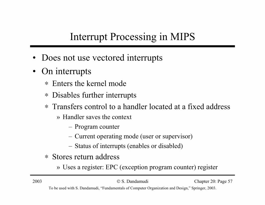
Interrupt Processing in MIPS
• Does not use vectored interrupts• On interrupts
∗ Enters the kernel mode∗ Disables further interrupts∗ Transfers control to a handler located at a fixed address
» Handler saves the context– Program counter– Current operating mode (user or supervisor)– Status of interrupts (enables or disabled)
∗ Stores return address» Uses a register: EPC (exception program counter) register
2003To be used with S. Dandamudi, “Fundamentals of Computer Organization and Design,” Springer, 2003.
S. Dandamudi Chapter 20: Page 58
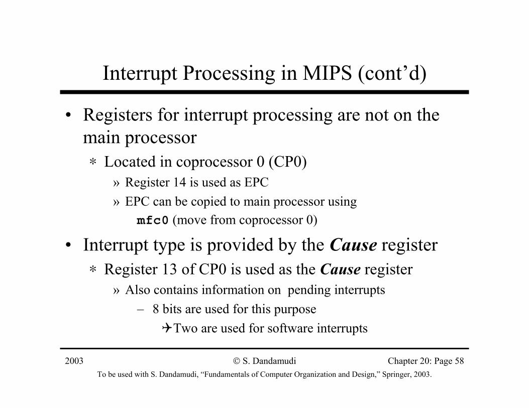
Interrupt Processing in MIPS (cont’d)
• Registers for interrupt processing are not on the main processor∗ Located in coprocessor 0 (CP0)
» Register 14 is used as EPC» EPC can be copied to main processor using
mfc0 (move from coprocessor 0)
• Interrupt type is provided by the Cause register∗ Register 13 of CP0 is used as the Cause register
» Also contains information on pending interrupts– 8 bits are used for this purpose
Two are used for software interrupts
2003To be used with S. Dandamudi, “Fundamentals of Computer Organization and Design,” Springer, 2003.
S. Dandamudi Chapter 20: Page 59
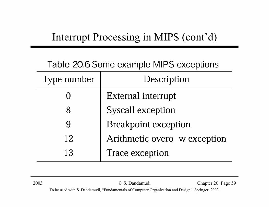
Interrupt Processing in MIPS (cont’d)
2003To be used with S. Dandamudi, “Fundamentals of Computer Organization and Design,” Springer, 2003.
S. Dandamudi Chapter 20: Page 60
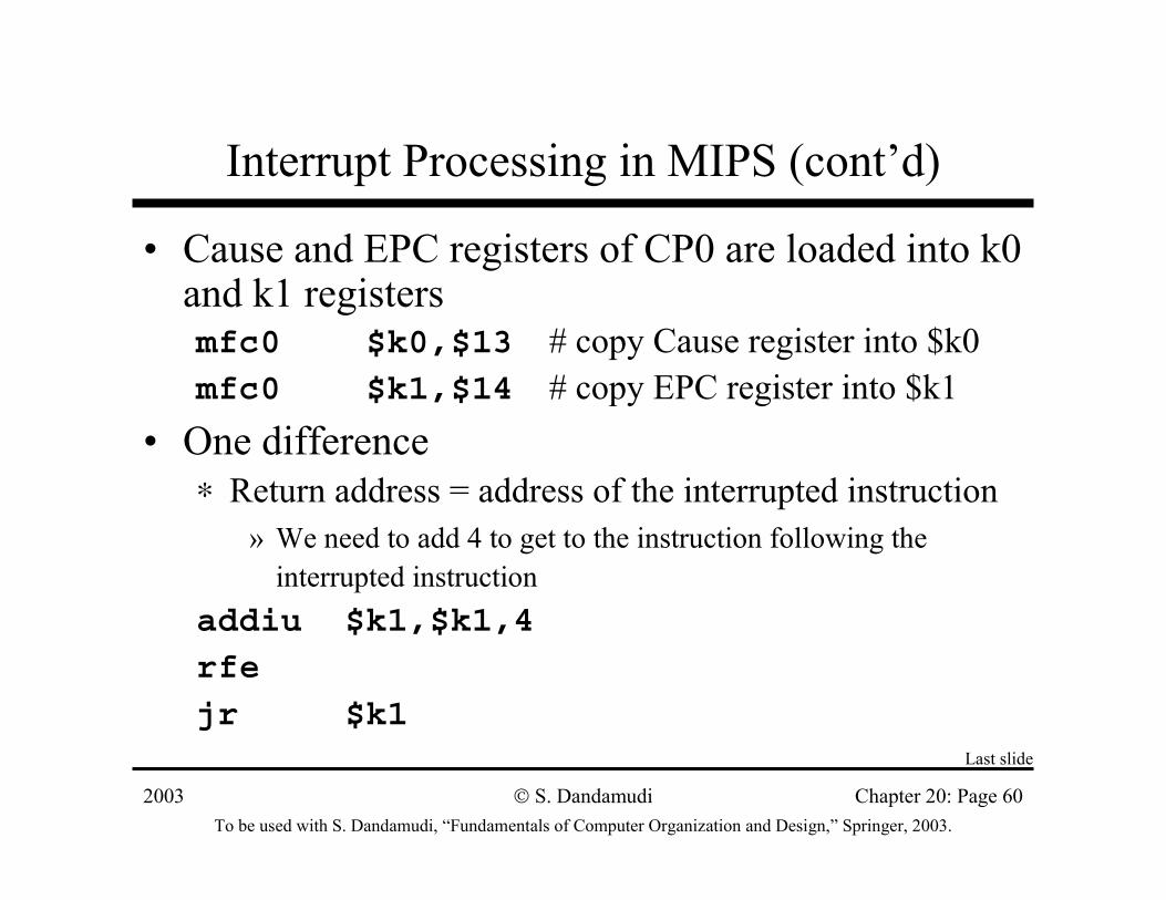
Interrupt Processing in MIPS (cont’d)
• Cause and EPC registers of CP0 are loaded into k0 and k1 registersmfc0 $k0,$13 # copy Cause register into $k0mfc0 $k1,$14 # copy EPC register into $k1
• One difference∗ Return address = address of the interrupted instruction
» We need to add 4 to get to the instruction following the interrupted instruction
addiu $k1,$k1,4
rfe
jr $k1Last slide