Embed Size (px)
Citation preview
TROLEX LIMITEDNewby Road
Haze l Grove, Stockport ,Chesh i re SK7 5DY, UK.
+44 (0)161-483 1435sa les@tro lex .comwww.tro lex .com
t e l :e - m a i l :i n t e r n e t :
1
I N S T A L L A T I O N & O P E R A T I N G D A T A
INTRINSICALLY SAFE
POWER SUPPLY
(Exi)
of 12 ISSUE A: 03/04
T X 6 6 2 0
Further copies of this document are available from
trolex.com
P R O D U C TC O N T R O L & D I S P L A Y
T X 6 6 3 0
T X 6 6 3 0
C O N T E N T S
P R O D U C TC O N T R O L & D I S P L A Y
T X 6 6 2 0
ISSUE A: 03/04
I N S T A L L A T I O N & O P E R A T I N G D A T A
2 of 12
Page
1. PRINCIPAL OPERATING FEATURES 3
2. TECHNICAL DETAILS 3
3. CONFORMITY CHECK 4
4. DIMENSIONS 5
5. CONNECTIONS 5
6. ISOLATING RELAYS 6
7. PRECAUTIONS 9
8. CERTIF ICATION AND STANDARDS 10
T X 6 6 3 0
2T E C H N I C A L
D E T A I L S
P R O D U C TC O N T R O L & D I S P L A Y
T X 6 6 2 0
ISSUE A: 03/04
I N S T A L L A T I O N & O P E R A T I N G D A T A
3 of 12
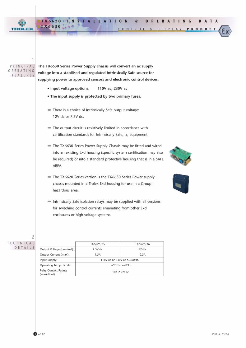
The TX6630 Series Power Supply chassis will convert an ac supply
voltage into a stabilised and regulated Intrinsically Safe source for
supplying power to approved sensors and electronic control devices.
• Input voltage options: 110V ac, 230V ac
• The input supply is protected by two primary fuses.
••••••••••••••• There is a choice of Intrinsically Safe output voltage:
12V dc or 7.5V dc.
••••••••••••••• The output circuit is resistively limited in accordance with
certification standards for Intrinsically Safe, ia, equipment.
••••••••••••••• The TX6630 Series Power Supply Chassis may be fitted and wired
into an existing Exd housing (specific system certification may also
be required) or into a standard protective housing that is in a SAFE
AREA.
••••••••••••••• The TX6620 Series version is the TX6630 Series Power supply
chassis mounted in a Trolex Exd housing for use in a Group I
hazardous area.
••••••••••••••• Intrinsically Safe isolation relays may be supplied with all versions
for switching control currents emanating from other Exd
enclosures or high voltage systems.
1P R I N C I P A L
O P E R A T I N GF E A T U R E S
TX6625/35 TX6626/36
Output Voltage (nominal): 7.5V dc 12Vdc
Output Current (max): 1.5A 0.5A
Input Supply: 110V ac or 230V ac 50/60Hz.
Operating Temp. Limits: –5°C to +70°C.
Relay Contact Rating: 10A 230V ac.(where fitted)
T X 6 6 3 0P R O D U C TC O N T R O L & D I S P L A Y
T X 6 6 2 0
3C O N F O R M I T Y
C H E C K
ISSUE A: 03/04
I N S T A L L A T I O N & O P E R A T I N G D A T A
4 of 12
••••••••••••••• Does the supply voltage marked on the product agree with
the locally available supply?
••••••••••••••• Check that the output current rating marked on the product
is adequate for the total current demand of the system being
installed.
••••••••••••••• Is the Power Supply mounted in the correct enclosure for the
application?
••••••••••••••• Ensure that the Power Supply certification details are fully
compliant with the monitoring system requirements.
If in any doubt, please contact the Trolex Sales department.
••••••••••••••• Is the output voltage correct for the system being used?
••••••••••••••• If isolating relays are fitted, is the voltage rating of the coils
correct?
••••••••••••••• If isolating relays are fitted, are the relay parameters suitable
for the load being switched?
110V ac • 230V ac
0.5A • 1.5A
Exd or Safe Area
Exi Group I
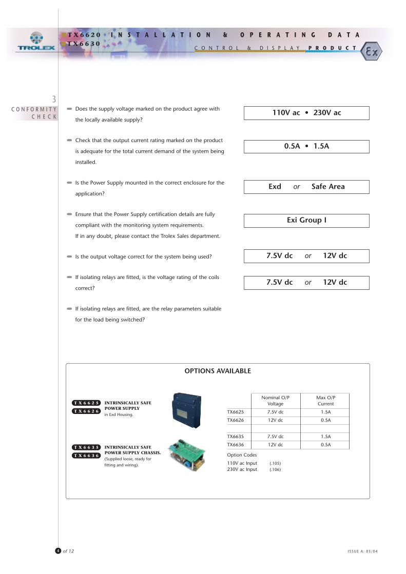
OPTIONS AVAILABLE
INTRINSICALLY SAFEPOWER SUPPLYin Exd Housing.
T X 6 6 2 5
INTRINSICALLY SAFEPOWER SUPPLY CHASSIS.(Supplied loose, ready for
fitting and wiring).
T X 6 6 3 5
Nominal O/P Max O/PVoltage Current
TX6625 7.5V dc 1.5A
TX6626 12V dc 0.5A
TX6635 7.5V dc 1.5A
TX6636 12V dc 0.5A
Option Codes
110V ac Input (.105)
230V ac Input (.106)
7.5V dc or 12V dc
7.5V dc or 12V dc
T X 6 6 2 6
T X 6 6 3 6
T X 6 6 3 0
5C O N N E C T I O N S
P R O D U C TC O N T R O L & D I S P L A Y
T X 6 6 2 0
4D I M E N S I O N S
( i n m m . )
ISSUE A: 03/04
I N S T A L L A T I O N & O P E R A T I N G D A T A
5 of 12
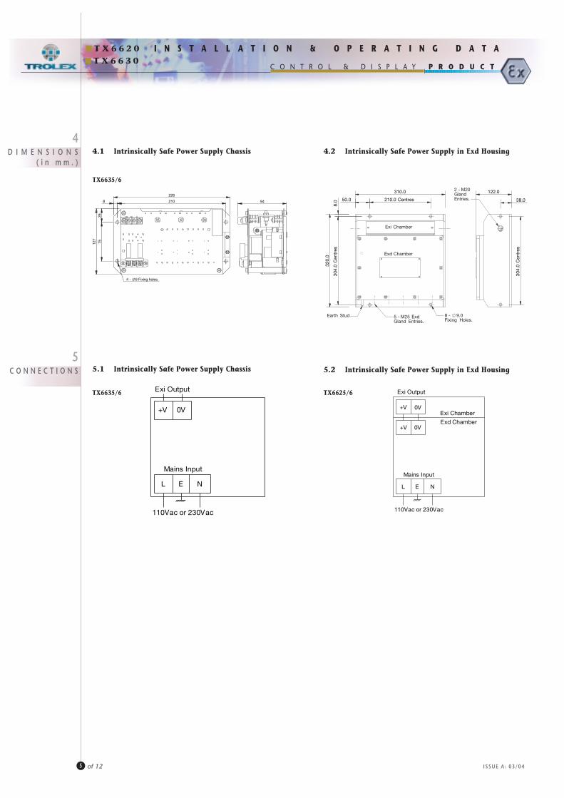
4.2 Intrinsically Safe Power Supply in Exd Housing4.1 Intrinsically Safe Power Supply Chassis
5.2 Intrinsically Safe Power Supply in Exd Housing5.1 Intrinsically Safe Power Supply Chassis
310.0
50.0 210.0 Centres
320.
0
304.
0 C
entr
es8.
0
8 - 9.0Fixing Holes.
Earth Stud 5 - M25 ExdGland Entries.
Exi Chamber
Exd Chamber
38.0
304.
0 C
entr
es
122.02 - M20GlandEntries.
+V 0V
Exi Output
L E N
Mains Input
110Vac or 230Vac
TX6635/6
210
226
75127
26
8
4 - 6 Fixing holes.
94
TX6635/6 TX6625/6
+V 0V
Exi Output
L E N
Mains Input
110Vac or 230Vac
0V+VExi Chamber
Exd Chamber
T X 6 6 3 0
6I S O L A T I N G
R E L A Y S
ISSUE A: 03/04
I N S T A L L A T I O N & O P E R A T I N G D A T A
6 of 12
T X 6 6 2 0
P R O D U C TC O N T R O L & D I S P L A Y
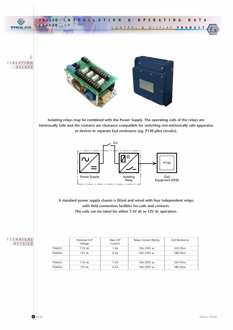
Isolating relays may be combined with the Power Supply. The operating coils of the relays are
Intrinsically Safe and the contacts are clearance compatible for switching non-intrinsically safe apparatus
or devices in separate Exd enclosures (eg. P130 pilot circuits).
A standard power supply chassis is fitted and wired with four independent relays
with field connection facilities for coils and contacts.
The coils can be rated for either 7.5V dc or 12V dc operation.
Power Supply IsolatingRelay
ExdEquipment (GEB)
Exi
P130
Nominal O/P Max O/P Relay Contact Rating Coil ResistanceVoltage Current
TX6625 7.5V dc 1.5A 10A 230V ac 324 Ohm
TX6626 12V dc 0.5A 10A 230V ac 580 Ohm
TX6635 7.5V dc 1.5A 10A 230V ac 324 Ohm
TX6636 12V dc 0.5A 10A 230V ac 580 Ohm
T E C H N I C A LD E T A I L S
T X 6 6 3 0
C O N N E C T I O N S
D I M E N S I O N S( i n m m . )
ISSUE A: 03/04
I N S T A L L A T I O N & O P E R A T I N G D A T A
7 of 12
T X 6 6 2 0
P R O D U C TC O N T R O L & D I S P L A Y
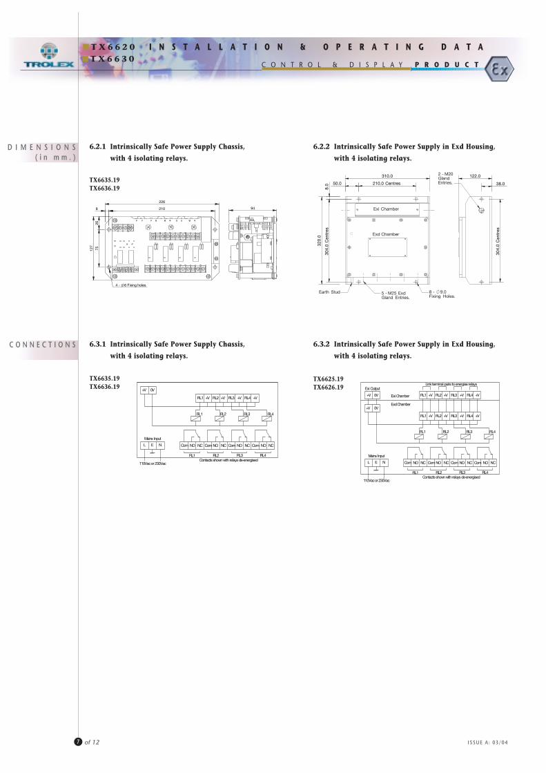
6.2.1 Intrinsically Safe Power Supply Chassis,
with 4 isolating relays.
6.3.1 Intrinsically Safe Power Supply Chassis,
with 4 isolating relays.
6.2.2 Intrinsically Safe Power Supply in Exd Housing,
with 4 isolating relays.
6.3.2 Intrinsically Safe Power Supply in Exd Housing,
with 4 isolating relays.
310.0
50.0 210.0 Centres
320.
0
304.
0 C
entr
es8.
0
8 - 9.0Fixing Holes.
Earth Stud 5 - M25 ExdGland Entries.
Exi Chamber
Exd Chamber
38.0
304.
0 C
entr
es
122.02 - M20GlandEntries.
+V 0V
Exi Output
Mains Input
110Vacor 230Vac
L E N
RL2 RL3 RL4
RL1 RL4RL3RL2
RL1 RL4RL3RL2
Com Com Com ComNO NO NO NO NCNCNCNC
+V +V +V +VRL1
Link terminal pairs toenergise relays
Contactsshown with relays de-energised
0V+V RL1 +V+V+V+V RL4RL3RL2Exi Chamber
ExdChamber
TX6635.19TX6636.19
TX6635.19TX6636.19
TX6625.19TX6626.19
210
226
8
7526
127
4 - 6 Fixing holes
94
+V 0V
Mains Input
110Vacor 230Vac
L E N
RL2 RL3 RL4
RL1 RL4RL3RL2
RL1 RL4RL3RL2
Com Com Com ComNO NO NO NO NCNCNCNC
+V +V +V +VRL1
Contactsshown with relays de-energised
T X 6 6 3 0
ISSUE A: 03/04
I N S T A L L A T I O N & O P E R A T I N G D A T A
8 of 12
T X 6 6 2 0
P R O D U C TC O N T R O L & D I S P L A Y
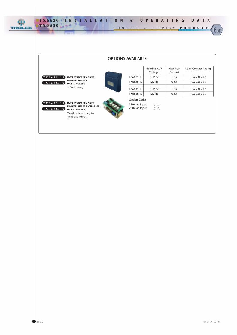
OPTIONS AVAILABLE
INTRINSICALLY SAFEPOWER SUPPLYWITH RELAYSin Exd Housing.
T X 6 6 2 5 . 1 9
INTRINSICALLY SAFEPOWER SUPPLY CHASSISWITH RELAYS.(Supplied loose, ready for
fitting and wiring).
T X 6 6 3 5 . 1 9
Nominal O/P Max O/P Relay Contact RatingVoltage Current
TX6625.19 7.5V dc 1.5A 10A 230V ac
TX6626.19 12V dc 0.5A 10A 230V ac
TX6635.19 7.5V dc 1.5A 10A 230V ac
TX6636.19 12V dc 0.5A 10A 230V ac
Option Codes
110V ac Input (.105)
230V ac Input (.106)
T X 6 6 2 6 . 1 9
T X 6 6 3 6 . 1 9
T X 6 6 3 0
7P R E C A U T I O N S
ISSUE A: 03/04
I N S T A L L A T I O N & O P E R A T I N G D A T A
9 of 12
T X 6 6 2 0
P R O D U C TC O N T R O L & D I S P L A Y
••••••••••••••••••• Ensure that all covers on Exd housings and their fixing devices are properly secured in compliance with statutory Exd
regulations before switching on the input supply.
••••••••••••••••••• Never remove the cover of an Exd housing whilst the input supply is connected. Isolate elsewhere before removing the
cover in accordance with statutory regulations.
••••••••••••••••••• The housing of all power supplies must be securely earthed in compliance with statutory regulations.
••••••••••••••••••• Carry out a current consumption audit to ensure that the maximum current loading of the power supply is not
exceeded.
••••••••••••••••••• Ensure that the installation of the power supply, particularly with regard to the connecting cables, complies with the
certification parameters (section 8).
••••••••••••••••••• Exd housings must be inspected and maintained regularly in accordance with statutory regulations.
••••••••••••••••••• Use only the correct Trolex replacement fuses (section 8). Do not substitute any form of equivalent or linking device.
••••••••••••••••••• The TX6630 Series Exi Power Supply must be mounted in an approved Exd housing when located in a hazardous area.
••••••••••••••••••• All cables entering the Exd housing must be terminated with suitable Exd certified cable glands.
••••••••••••••••••• The cabling between the Power Supply and other approved intrinsically safe devices must comply with the cable
parameters specified in the appropriate Ex certification of the device.
••••••••••••••••••• Never connect two power supplies in parallel, or employ external circuitry that results in two Intrinsically Safe Power
Supplies circulating in one system. This will contravene the limits of Intrinsic Safety.
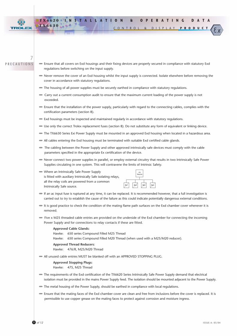
••••••••••••••••••• Where an Intrinsically Safe Power Supply
is fitted with auxiliary Intrinsically Safe isolating relays,
all the relay coils are powered from a common
Intrinsically Safe source.
••••••••••••••••••• If an ac input fuse is ruptured at any time, it can be replaced. It is recommended however, that a full investigation is
carried out to try to establish the cause of the failure as this could indicate potentially dangerous external conditions.
••••••••••••••••••• It is good practice to check the condition of the mating flame path surfaces on the Exd chamber cover whenever it is
removed.
••••••••••••••••••• Five x M25 threaded cable entries are provided on the underside of the Exd chamber for connecting the incoming
Power Supply and for connections to relay contacts if these are fitted.
Approved Cable Glands:
Hawke: 650 series Compound Filled M25 Thread
Hawke: 650 series Compound Filled M20 Thread (when used with a M25/M20 reducer).
Approved Thread Reducers:
Hawke: 476/R, M25/M20 Thread
••••••••••••••••••• All unused cable entries MUST be blanked off with an APPROVED STOPPING PLUG.
Approved Stopping Plugs:
Hawke: 475, M25 Thread
••••••••••••••••••• The requirements of the Exd certification of the TX6620 Series Intrinsically Safe Power Supply demand that electrical
isolation must be provided in the mains Power Supply feed. The isolation should be mounted adjacent to the Power Supply.
••••••••••••••••••• The metal housing of the Power Supply, should be earthed in compliance with local regulations.
••••••••••••••••••• Ensure that the mating faces of the Exd chamber cover are clean and free from inclusions before the cover is replaced. It is
permissible to use copper grease on the mating faces to protect against corrosion and moisture ingress.
I.S.Source
RL1 RL2 RL3 RL4
T X 6 6 3 0P R O D U C TC O N T R O L & D I S P L A Y
T X 6 6 2 0
8C E R T I F I C A T I O N
A N DS T A N D A R D S
ISSUE A: 03/04
I N S T A L L A T I O N & O P E R A T I N G D A T A
10 of 12
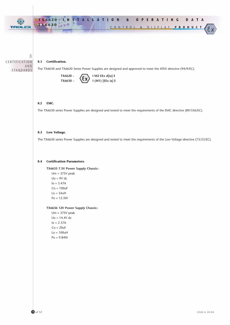
8.1 Certification.
The TX6630 and TX6620 Series Power Supplies are designed and approved to meet the ATEX directive (94/9/EC).
TX6620 – I M2 EEx d[ia] I
TX6630 – I (M1) [EEx ia] I
8.2 EMC.
The TX6630 series Power Supplies are designed and tested to meet the requirements of the EMC directive (89/336/EC).
8.3 Low Voltage.
The TX6630 series Power Supplies are designed and tested to meet the requirements of the Low Voltage directive (73/23/EC).
8.4 Certification Parameters.
TX6635 7.5V Power Supply Chassis:-
Um = 375V peak
Uo = 9V dc
Io = 3.47A
Co = 100uF
Lo = 54uH
Po = 12.5W
TX6636 12V Power Supply Chassis:-
Um = 375V peak
Uo = 14.4V dc
Io = 2.37A
Co = 20uF
Lo = 100uH
Po = 9.84W
T X 6 6 3 0P R O D U C TC O N T R O L & D I S P L A Y
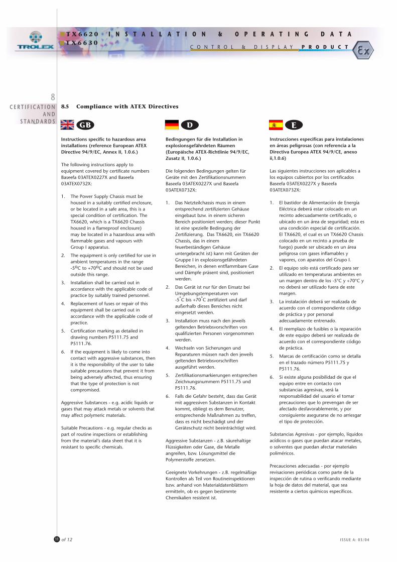
Instructions specific to hazardous areainstallations (reference European ATEXDirective 94/9/EC, Annex II, 1.0.6.)
The following instructions apply toequipment covered by certificate numbersBaseefa 03ATEX0227X and Baseefa03ATEX0732X:
1. The Power Supply Chassis must be housed in a suitably certified enclosure, or be located in a safe area, this is a special condition of certification. The TX6620, which is a TX6620 Chassis housed in a flameproof enclosure) may be located in a hazardous area withflammable gases and vapours with Group I apparatus.
2. The equipment is only certified for use inambient temperatures in the range-5oC to +70oC and should not be used outside this range.
3. Installation shall be carried out in accordance with the applicable code of practice by suitably trained personnel.
4. Replacement of fuses or repair of this equipment shall be carried out in accordance with the applicable code of practice.
5. Certification marking as detailed in drawing numbers P5111.75 and P5111.76.
6. If the equipment is likely to come into contact with aggressive substances, thenit is the responsibility of the user to take suitable precautions that prevent it from being adversely affected, thus ensuring that the type of protection is not compromised.
Aggressive Substances - e.g. acidic liquids orgases that may attack metals or solvents thatmay affect polymeric materials.
Suitable Precautions - e.g. regular checks aspart of routine inspections or establishingfrom the material’s data sheet that it isresistant to specific chemicals.
Bedingungen für die Installation inexplosionsgefährdeten Räumen(Europäische ATEX-Richtlinie 94/9/EC,Zusatz II, 1.0.6.)
Die folgenden Bedingungen gelten fürGeräte mit den ZertifikationsnummernBaseefa 03ATEX0227X und Baseefa03ATEX0732X:
1. Das Netzteilchassis muss in einem entsprechend zertifizierten Gehäuse eingebaut bzw. in einem sicheren Bereich positioniert werden; dieser Punktist eine spezielle Bedingung der Zertifizierung. Das TX6620, ein TX6620Chassis, das in einem feuerbeständigen Gehäuse untergebracht ist) kann mit Geräten der Gruppe I in explosionsgefährdeten Bereichen, in denen entflammbare Gase und Dämpfe präsent sind, positioniert werden.
2. Das Gerät ist nur für den Einsatz bei Umgebungstemperaturen von-5°C bis +70°C zertifiziert und darf außerhalb dieses Bereiches nicht eingesetzt werden.
3. Installation muss nach den jeweils geltenden Betriebsvorschriften von qualifizierten Personen vorgenommen werden.
4. Wechseln von Sicherungen und Reparaturen müssen nach den jeweils geltenden Betriebsvorschriften ausgeführt werden.
5. Zertifikationsmarkierungen entsprechen Zeichnungsnummern P5111.75 und P5111.76.
6. Falls die Gefahr besteht, dass das Gerät mit aggressiven Substanzen in Kontakt kommt, obliegt es dem Benutzer, entsprechende Maßnahmen zu treffen, dass es nicht beschädigt und der Geräteschutz nicht beeinträchtigt wird.
Aggressive Substanzen - z.B. säurehaltigeFlüssigkeiten oder Gase, die Metalleangreifen, bzw. Lösungsmittel diePolymerstoffe zersetzen.
Geeignete Vorkehrungen - z.B. regelmäßigeKontrollen als Teil von Routineinspektionenbzw. anhand von Materialdatenblätternermitteln, ob es gegen bestimmteChemikalien resistent ist.
Instrucciones especificas para instalacionesen áreas peligrosas (con referencia a laDirectiva Europea ATEX 94/9/CE, anexoii,1.0.6)
Las siguientes instrucciones son aplicables alos equipos cubiertos por los certificadosBaseefa 03ATEX0227X y Baseefa03ATEX0732X:
1. El bastidor de Alimentación de Energía Eléctrica deberá estar colocado en un recinto adecuadamente certificado, o ubicado en un área de seguridad; esta esuna condición especial de certificación. El TX6620, el cual es un TX6620 Chassiscolocado en un recinto a prueba de fuego) puede ser ubicado en un área peligrosa con gases inflamables y vapores, con aparatos del Grupo I.
2. El equipo solo está certificado para ser utilizado en temperaturas ambientes en un margen dentro de los -5°C y +70°C yno deberá ser utilizado fuera de este margen.
3. La instalación deberá ser realizada de acuerdo con el correspondiente código de práctica y por personal adecuadamente entrenado.
4. El reemplazo de fusibles o la reparación de este equipo deberá ser realizada de acuerdo con el correspondiente código de práctica.
5. Marcas de certificación como se detalla en el trazado número P5111.75 y P5111.76.
6. Si existe alguna posibilidad de que el equipo entre en contacto con substancias agresivas, será la responsabilidad del usuario el tomar precauciones que lo prevengan de ser afectado desfavorablemente, y por consiguiente asegurarse de no arriesgar el tipo de protección.
Substancias Agresivas - por ejemplo, líquidosacídicos o gases que puedan atacar metales,o solventes que puedan afectar materialespoliméricos.
Precauciones adecuadas - por ejemplorevisaciones periódicas como parte de lainspección de rutina o verificando mediantela hoja de datos del material, que searesistente a ciertos químicos específicos.
GB D E
8.5 Compliance with ATEX Directives8
C E R T I F I C A T I O NA N D
S T A N D A R D S
T X 6 6 2 0
ISSUE A: 03/04
I N S T A L L A T I O N & O P E R A T I N G D A T A
11 of 12
T X 6 6 3 0P R O D U C TC O N T R O L & D I S P L A Y
C E R T I F I C A T I O NA N D
S T A N D A R D S
Instructies met specifieke betrekking opinstallaties voor gevaarlijke ruimten(naar Europese ATEX Richtlijn 94/9/EC, BijlageII, 1.0.6.)
De volgende instructies zijn van toepassing oponder Certificaat nummer Baseefa 03ATEX0227Xen Baseefa 03ATEX0732X vallende apparatuur:
1. De stroomvoorzieningschassis moet ondergebracht worden in een officieel geschikt verklaarde behuizing of in een veilige ruimte: dit is een speciale voorwaarde voor certificering. De TX6620, oftewel een TX6620 Chassis ondergebracht in een vlamveilige behuizing) mag in een gevaarlijke ruimte met vlambare gassen en dampen worden ondergebracht met apparatuur van Groep I.
2. De apparatuur is alleen officieel geschikt verklaard voor gebruik bij een omgevingstemperatuur tussen–5°C en +70°C en mag niet gebruikt worden buiten deze minimum- en maximumtemperaturen.
3. Installatiewerkzaamheden dienenuitgevoerd te worden door geschikt opgeleid personeel in overeenstemming met de van toepassing zijnde praktijkcode.
4. Het vervangen van smeltveiligheden en reparatiewerkzaamheden dienen uitgevoerd te worden in overeenstemming met de van toepassing zijnde praktijkcode.
5. Markering van de certificering volgens Tekening P5111.75 en P5111.76.
6. Als het waarschijnlijk is dat de apparatuur in aanraking zal komen met agressieve stoffen, dan is het de verantwoordelijkheid van de gebruiker om geschikte voorzorgsmaatregelen te nemen om te voorkomen dat de apparatuur aangetast wordt en er zo voor te zorgen dat het type bescherming niet in gevaar gebracht wordt.
Agressieve stoffen – bijv. zure vloeistoffen ofgassen die metalen kunnen aantasten ofweloplossingen die een vergelijkbaar effect kunnenhebben op polymeren stoffen.
Geschikte voorzorgsmaatregelen – bijv.regelmatig controleren als onderdeel van routineinspecties of naar aanleiding van hetgegevensblad voor materialen vaststellen dat hetmateriaal tegen bepaalde chemicaliën kan.
NL
Spesifikk informasjon for installasjoner ieksplosjonsfarlige områder (ref. EuropeiskATEX Direktiv 94/9/EC, Bilag II, 1.0.6.)
Følgende instrukser gjelder for utstyr dekketav sertifikatnummer Baseefa 03ATEX0227Xog Baseefa 03ATEX0732X:
1. Kraftforsyningschassiset må plasseres i enpassende sertifisert kasse, eller plasseres på et ikke-eksplosjonsfarlig område, dette er en betingelse for sertifiseringen. TX6620, som er en TX6620 Chassis plassert i en flammesikker kasse) kan plasseres på et eksplosjonsfarlig område med brannfarlige gasser og damp med Gruppe 1 apparater.
2. Utstyret er kun sertifisert for bruk i omgivelsestemperaturer fra-5ºC til +70ºC og må ikke brukes utenfordisse temperaturområdene.
3. Innstallering må utføres av kompetent personale ifølge gjeldende regler.
4. Utskifting av sikringer eller reparasjoner på dette utstyret må kun utføres ifølge gjeldende regler.
5. Sertifiseringsmerkingen vises på tegninger nummer P5111.75 og P5111.76.
6. Hvis utstyret sannsynligvis vil komme i kontakt med aggressive stoffer så er det brukerens ansvar å ta passende forholdsregler for å unngå at det blir skadet, og således sikre at beskyttelsen ikke forringes.
Aggressive stoffer - f.eks. etsende væsker oggasser som kan angripe metaller ellerløsemidler som kan påvirke polymeriskematerialer.
Passende forholdsregler - f.eks. regelmessiginspeksjon som en del av rutinesjekking ellerfastslå fra materialets dataark at det ermotstandsdyktig mot aktuelle kjemikalier.
N
T X 6 6 2 0
ISSUE A: 03/04
I N S T A L L A T I O N & O P E R A T I N G D A T A
12 of 12
Norme specifiche alle installazioni in zonea rischio (riferimento Direttiva EuropeaATEX 94/9/EC, Allegato II, 1.0.6.)
Le norme che seguono si applicano alleapparecchiature disciplinate dai certificati n.Baseefa 03ATEX0227X e Baseefa03ATEX0732X:
1. Il telaio dell’alimentatore deve essere alloggiato in un contenitore idoneamente omologato, od essere sistemato in una zona sicura; questa è una condizione specifica della certificazione. Il tipo TX6620, che è la versione del TX6620 Chassis alloggiata in un contenitore antideflagrante) può essere sistemato in una zona a rischio con gas e vapori infiammabili con apparecchiature del Gruppo I.
2. L’apparecchio è certificato solo per l’utilizzo ad una temperatura ambiente compresa tra –5°C e +70°C e non deve essere usato al di fuori di questo campo.
3. L’installazione deve essere eseguita in conformità al codice di procedura pertinente da personale opportunamente addestrato.
4. La sostituzione dei fusibili o la riparazione di questo apparecchio devono essere eseguite in conformità al codice di procedura pertinente.
5. La marcatura di certificazione è quella indicata sui disegni numero P5111.75 e P5111.76.
6. Se è probabile che l’apparecchio venga a contatto con sostanze aggressive, è compito dell’utente prendere precauzioni idonee a impedire che ne siaattaccato, garantendo così che il tipo di protezione non venga compromesso.
Sostanze aggressive sono, ad esempio, liquidio gas acidi che possono attaccare i metalli, osolventi che possono colpire i materialipolimerici.
Precauzioni idonee sono, ad esempio,controlli regolari che fanno parte di ispezioniordinarie, o informazioni reperite dallascheda tecnica del materiale che conferminoche è resistente a prodotti chimici specifici.
I
P R O T E C T I N GT H E
E N V I R O N M E N T
Many of our products are often used to monitor the quality of environmental conditions consequently Trolex is also
particularly aware of the need to protect human health and the environment in which we live.
The Company has instituted a radical environment protection policy to ensure that all aspects of our manufacturing
programme have the minimum possible detrimental impact on the environment. This covers all stages beginning with
sustainable product design supported by careful selection of the materials used in their production, through to
managed recovery and disposal at the end of the useful life of a product.
This policy also incorporates the principles of the Waste Electrical and Electronics Equipment (WEEE) directive, and the
associated Restriction of Hazardous Substances (RoHS) directive, to be implemented in EU countries.
Progress is already well advanced on the introduction of a completely new range of products that maximise the
central principle of sustainable design with the intention of reducing the end-of-life cost to the end user.
All Trolex products are manufactured to exacting standards in accordance with our stringent quality control ethos.
Having chosen to use one of our products will, in itself, guarantee extended durability and a long operating life,
endorsed by our commitment to recycling and recovery.
• All packaging materials are carefully selected to be bio-degradable or re-cycleable where possible.
• All plastic materials are identified for recycling purposes and re-cycled materials are used where it is possible to do so.
• Printing paper and material are sourced from suppliers that have a declared environmental management system.
• Product design centred around high quality and long term durability. Modular architecture both in construction and software design suitable for future upgrades and adaptability to alternative duty.
• Ease of product disassembly, minimisation of fixing devices, and clear separation of functional parts to benefit re-use and re-cycling.
• Control and monitoring of suppliers of components and sub-assemblies. Deal only with suppliers that have a defined commitment to environmental monitoring principles.
• Control the use of restricted substances within the design process. Deal only with suppliers that have a defined commitment to the control of restricted substances.
• Provide an efficient high speed service within Trolex for repair, refurbishing and conversion of products for alternative duty.
• Provision of an end-of-life product Take-back service for recovery, re-use, and recycling of electrical and electroniccomponents. Retain the packaging of a new product and re-use it to return the device to us at the end of its working life. Trolex will guarantee to recover all materials and components, where practicable and arrange for them to be re-cycled in an appropriate and in a safe manner.
TROLEX LIMITEDNewby Road, Haze l Grove, Stockport , Chesh i re SK7 5DY, UK.
T: +44 (0)161-483 1435E: sa les@tro lex .com W: www.tro lex .com
ISSUE A: 03/04
I N S T A L L A T I O N & O P E R A T I N G D A T AT X 6 6 2 0
P R O D U C TC O N T R O L & D I S P L A YT X 6 6 3 0

![[XLS] · Web viewAC UARINI AC URUCARA AC URUCURITUBA AC AGRESTE AC AMAPA AC BAILIQUE AC BEIROL AC CALCOENE AC CENTRO AC CUTIAS AC EQUATORIAL AC FERREIRA GOMES AC ITAUBAL AC LARANJAL](https://img.pdfslide.net/doc/110x75/5c5be47c09d3f245368c84d6/xls-web-viewac-uarini-ac-urucara-ac-urucurituba-ac-agreste-ac-amapa-ac-bailique.jpg)