Embed Size (px)
Citation preview
AV Receiver
HT-R380
Instruction Manual
Thank you for purchasing an Onkyo AV Receiver. Please read this manual thoroughly before making connections and plugging in the unit.Following the instructions in this manual will enable you to obtain optimum performance and listening enjoyment from your new AV Receiver. Please retain this manual for future reference.
Contents
Introduction ...................................2
Connections.................................11
Turning On & Basic Operations ......18
Advanced Operations .................28
Controlling iPod & Other Components............................37
Others...........................................44
En
2En
Important Safety Instructions1. Read these instructions.2. Keep these instructions.3. Heed all warnings.4. Follow all instructions.5. Do not use this apparatus near water.6. Clean only with dry cloth.7. Do not block any ventilation openings. Install in
accordance with the manufacturer’s instructions.8. Do not install near any heat sources such as radiators,
heat registers, stoves, or other apparatus (including amplifiers) that produce heat.
9. Do not defeat the safety purpose of the polarized or grounding-type plug. A polarized plug has two blades with one wider than the other. A grounding type plug has two blades and a third grounding prong. The wide blade or the third prong are provided for your safety. If the provided plug does not fit into your outlet, consult an electrician for replacement of the obsolete outlet.
10. Protect the power cord from being walked on or pinched particularly at plugs, convenience receptacles, and the point where they exit from the apparatus.
11. Only use attachments/accessories specified by the manufacturer.
12. Use only with the cart, stand, tripod, bracket, or table speci-fied by the manufacturer, or sold with the apparatus. When a cart is used, use caution when moving the cart/appara-tus combination to avoid injury from tip-over.
13. Unplug this apparatus during lightning storms or when unused for long periods of time.
14. Refer all servicing to qualified service personnel. Ser-vicing is required when the apparatus has been dam-aged in any way, such as power-supply cord or plug is damaged, liquid has been spilled or objects have fallen into the apparatus, the apparatus has been exposed to rain or moisture, does not operate normally, or has been dropped.
15. Damage Requiring ServiceUnplug the apparatus from the wall outlet and refer servicing to qualified service personnel under the fol-lowing conditions:A. When the power-supply cord or plug is damaged,B. If liquid has been spilled, or objects have fallen
into the apparatus,C. If the apparatus has been exposed to rain or water,D. If the apparatus does not operate normally by fol-
lowing the operating instructions. Adjust only those controls that are covered by the operating instructions as an improper adjustment of other controls may result in damage and will often require extensive work by a qualified technician to restore the apparatus to its normal operation,
E. If the apparatus has been dropped or damaged in any way, and
F. When the apparatus exhibits a distinct change in performance this indicates a need for service.
16. Object and Liquid EntryNever push objects of any kind into the apparatus through openings as they may touch dangerous volt-age points or short-out parts that could result in a fire or electric shock.The apparatus shall not be exposed to dripping or splashing and no objects filled with liquids, such as vases shall be placed on the apparatus.Don’t put candles or other burning objects on top of this unit.
17. BatteriesAlways consider the environmental issues and follow local regulations when disposing of batteries.
18. If you install the apparatus in a built-in installation, such as a bookcase or rack, ensure that there is ade-quate ventilation.Leave 20 cm of free space at the top and sides and 10 cm at the rear. The rear edge of the shelf or board above the apparatus shall be set 10 cm away from the rear panel or wall, creating a flue-like gap for warm air to escape.
WARNING:TO REDUCE THE RISK OF FIRE OR ELECTRIC SHOCK, DO NOT EXPOSE THIS APPARATUS TO RAIN OR MOISTURE.
CAUTION:TO REDUCE THE RISK OF ELECTRIC SHOCK, DO NOT REMOVE COVER (OR BACK). NO USER-SERVICEABLE PARTS INSIDE. REFER SERVICING TO QUALIFIED SERVICE PERSONNEL.
The lightning flash with arrowhead symbol, within an equilateral triangle, is intended to alert the user to the presence of uninsulated “dangerous voltage” within the product’s enclosure that may be of sufficient magnitude to constitute a risk of electric shock to persons.
The exclamation point within an equilateral triangle is intended to alert the user to the presence of important operating and maintenance (servicing) instructions in the literature accompanying the appliance.
WARNINGRISK OF ELECTRIC SHOCK
DO NOT OPENRISQUE DE CHOC ELECTRIQUE
NE PAS OUVRIR
AVIS
PORTABLE CART WARNING
S3125A
3En
Precautions1. Recording Copyright—Unless it’s for personal use
only, recording copyrighted material is illegal without the permission of the copyright holder.
2. AC Fuse—The AC fuse inside the unit is not user-ser-viceable. If you cannot turn on the unit, contact your Onkyo dealer.
3. Care—Occasionally you should dust the unit all over with a soft cloth. For stubborn stains, use a soft cloth dampened with a weak solution of mild detergent and water. Dry the unit immediately afterwards with a clean cloth. Don’t use abrasive cloths, thinners, alco-hol, or other chemical solvents, because they may damage the finish or remove the panel lettering.
4. PowerWARNINGBEFORE PLUGGING IN THE UNIT FOR THE FIRST TIME, READ THE FOLLOWING SECTION CAREFULLY.AC outlet voltages vary from country to country. Make sure that the voltage in your area meets the volt-age requirements printed on the unit’s rear panel (e.g., AC 230 V, 50 Hz or AC 120 V, 60 Hz).
The power cord plug is used to disconnect this unit from the AC power source. Make sure that the plug is readily operable (easily accessible) at all times.
Pressing ON/STANDBY to select Standby mode does not fully shutdown the unit. If you do not intend to use the unit for an extended period, remove the power cord from the AC outlet.
5. Preventing Hearing LossCautionExcessive sound pressure from earphones and head-phones can cause hearing loss.
6. Batteries and Heat ExposureWarningBatteries (battery pack or batteries installed) shall not be exposed to excessive heat as sunshine, fire or the like.
7. Never Touch this Unit with Wet Hands—Never han-dle this unit or its power cord while your hands are wet or damp. If water or any other liquid gets inside this unit, have it checked by your Onkyo dealer.
8. Handling Notes • If you need to transport this unit, use the original
packaging to pack it how it was when you originally bought it.
• Do not leave rubber or plastic items on this unit for a long time, because they may leave marks on the case.
• This unit’s top and rear panels may get warm after prolonged use. This is normal.
• If you do not use this unit for a long time, it may not work properly the next time you turn it on, so be sure to use it occasionally.
For British modelsReplacement and mounting of an AC plug on the power supply cord of this unit should be performed only by qual-ified service personnel.
IMPORTANTThe wires in the mains lead are coloured in accordance with the following code:
Blue: NeutralBrown: Live
As the colours of the wires in the mains lead of this appa-ratus may not correspond with the coloured markings identifying the terminals in your plug, proceed as follows:The wire which is coloured blue must be connected to the terminal which is marked with the letter N or coloured black.The wire which is coloured brown must be connected to the terminal which is marked with the letter L or coloured red.
IMPORTANTThe plug is fitted with an appropriate fuse. If the fuse needs to be replaced, the replacement fuse must approved by ASTA or BSI to BS1362 and have the same ampere rat-ing as that indicated on the plug. Check for the ASTA mark or the BSI mark on the body of the fuse.If the power cord’s plug is not suitable for your socket out-lets, cut it off and fit a suitable plug. Fit a suitable fuse in the plug.
For European Models
Declaration of Conformity
We, ONKYO EUROPEELECTRONICS GmbHLIEGNITZERSTRASSE 6, 82194 GROEBENZELL, GERMANY
GROEBENZELL, GERMANY
ONKYO EUROPE ELECTRONICS GmbHK. MIYAGI
declare in own responsibility, that the ONKYO product described in this instruction manual is in compliance with the corresponding technical standards such as EN60065, EN55013, EN55020 and EN61000-3-2, -3-3.
4En
Supplied AccessoriesMake sure you have the following accessories:
* In catalogs and on packaging, the letter at the end of the prod-uct name indicates the color. Specifications and operations are the same regardless of color.
Installing the Batteries
Note
• If the remote controller doesn’t work reliably, try replacing the batteries.
• Don’t mix new and old batteries or different types of batteries.
• If you intend not to use the remote controller for a long time, remove the batteries to prevent damage from leak-age or corrosion.
• Remove expired batteries as soon as possible to prevent damage from leakage or corrosion.
Aiming the Remote Controller
To use the remote controller, point it at the AV receiver’s remote control sensor, as shown below.
Indoor FM antenna ( 16)
AM loop antenna ( 16)
Remote controller and two batteries (AA/R6) ( 4)
Using the Remote Controller
Batteries (AA/R6)
Remote control sensor
AV receiver
Approx. 5 m
5En
Contents
Important Safety Instructions ......................................... 2Precautions....................................................................... 3Supplied Accessories...................................................... 4
Using the Remote Controller .......................................... 4Features ............................................................................ 6Front & Rear Panels......................................................... 7
Front Panel..................................................................... 7Display............................................................................ 8Rear Panel ..................................................................... 8
Remote Controller............................................................ 9Controlling the AV Receiver ........................................... 9
About Home Theater...................................................... 10Speakers A and B ........................................................ 10Enjoying Home Theater................................................ 10
Connecting the AV Receiver ......................................... 11Connecting Your Speakers .......................................... 11About AV Connections ................................................. 13Connecting Components with HDMI ............................ 14Connecting External Components................................ 15Using the AUX INPUT jack on the front panel.............. 15Connecting Onkyo u Components ............................ 16Connecting Antenna..................................................... 16Which Connections Should I Use?............................... 17
Turning On/Off the AV Receiver ................................... 18Turning On ................................................................... 18Turning Off ................................................................... 18
Basic Operations............................................................ 19Playing the Connected Component.............................. 19Displaying Source Information ..................................... 19Using the Music Optimizer ........................................... 19Setting the Display Brightness ..................................... 19Muting the AV Receiver................................................ 20Using the Sleep Timer.................................................. 20Using Headphones....................................................... 20Changing the Input Display .......................................... 20Selecting Speakers A and B......................................... 20
Listening to the Radio ................................................... 21Using the Tuner............................................................ 21Presetting FM/AM Stations........................................... 22Using RDS.................................................................... 22
Recording ....................................................................... 24Using the Listening Modes ........................................... 25
Selecting Listening Modes ........................................... 25About Listening Modes................................................. 25
Advanced Setup .............................................................28On-screen Setup Menus...............................................28Common Procedures in Setup Menu ...........................28HDMI Input ...................................................................29Component (Component Video Input) ..........................29Digital Audio (Digital Audio Input).................................29Sp Config (Speaker Configuration)...............................30Sp Distance (Speaker Distance) ..................................30Level Cal (Level Calibration) ........................................31Audio Adjust .................................................................31Name Edit .....................................................................32Hardware ......................................................................32HDMI Setup ..................................................................32Using the Audio Settings ..............................................34Digital Input Signal Formats .........................................36Adjusting the Bass & Treble .........................................36
Controlling iPod .............................................................37Connecting an Onkyo Dock..........................................37Using the Onkyo Dock..................................................38Controlling Your iPod....................................................39
Controlling Other Components.....................................41Preprogrammed Remote Control Codes ......................41Entering Remote Control Codes...................................41Remote Control Codes for
Onkyo Components Connected via u .....................41Resetting REMOTE MODE Buttons .............................42Resetting the Remote Controller ..................................42Controlling Other Components .....................................42
Troubleshooting .............................................................44Specifications .................................................................48About HDMI.....................................................................49Using an RIHD-compatible TV, Player, or Recorder ...50
Introduction
Connections
Turning On & Basic Operations
Advanced Operations
Controlling iPod & Other Components
Others
To reset the AV receiver to its factory defaults, turn it on and, while holding down VCR/DVR, press ON/STANDBY ( 44).
6En
Features
Amplifier
• 100 Watts/Channel @ 6 ohms (IEC)• Optimum Gain Volume Circuitry• H.C.P.S. (High Current Power Supply) Massive High
Power Transformer
Processing
• HDMI (Ver.1.4 with Audio Return Channel, 3D), Deep-Color, x.v.Color*, Lip Sync, DTS*1-HD Master Audio, DTS-HD High Resolution Audio, Dolby TrueHD*2, Dolby Digital Plus, DSD and Multi-CH PCM
• Non-Scaling Configuration• A-Form Listening Mode Memory• Direct Mode• Music Optimizer*3 for Compressed Digital Music files• 192 kHz/24-bit D/A Converters• Powerful and Highly Accurate 32-bit Processing DSP
Connections
• 3 HDMI*4 Inputs and 1 Output
• Onkyo p for System Control• 3 Digital Inputs (2 Optical/1 Coaxial)• Component Video Switching (2 Inputs/1 Output)• Universal Port for the Dock for iPod*/DAB+ tuner mod-
ule
Miscellaneous
• 40 FM/AM Presets• EX.BASS for natural deeper bass• Crossover Adjustment
(40/50/60/80/100/120/150/200 Hz)• A/V Sync Control Function (up to 100 ms)• On-Screen Display via HDMI
*1
Manufactured under license under U.S. Patent #’s: 5,451,942; 5,956,674; 5,974,380; 5,978,762; 6,226,616; 6,487,535; 7,212,872; 7,333,929; 7,392,195; 7,272,567 & other U.S. and worldwide patents issued & pending. DTS is a registered trademark and the DTS logos, Symbol are trademarks of DTS, Inc. © 1996-2008 DTS, Inc. All Rights Reserved.
*2
Manufactured under license from Dolby Laboratories. “Dolby”, “Pro Logic” and the double-D symbol are trade-marks of Dolby Laboratories.
*3 Music Optimizer™ is a trademark of Onkyo Corporation.
*4
“HDMI, the HDMI Logo, and High-Definition Multimedia Interface are trademarks or registered trademarks of HDMI Licensing LLC in the United States and other countries.”
* Apple and iPod are trademarks of Apple Inc., registered in the U.S. and other countries.
* “x.v.Color” is a trademark of Sony Corporation.
7En
Front & Rear Panels
The actual front panel has various logos printed on it. They are not shown here for clarity.The page numbers in parentheses show where you can find the main explanation for each item.
a ON/STANDBY button ( 18)
b STANDBY indicator ( 18)
c HDMI THRU indicator ( 33)
d SPEAKERS A and B buttons ( 10, 20)
e Remote control sensor ( 4)
f TONE LEVEL and TONE buttons ( 36)
g Display ( 8)
h LISTENING MODE buttons ( 25)
i RT/PTY/TP button ( 22)
j MEMORY button ( 22)
k TUNING MODE button ( 21)
l DISPLAY button ( 19)
m SETUP button ( 28)
n TUNING, PRESET ( 21 to 22), arrow and ENTER buttons
o RETURN button
p MASTER VOLUME control ( 19)
q MUSIC OPTIMIZER button ( 19, 35)
r PHONES jack ( 20)
s Input selector buttons ( 19)
t AUX INPUT LINE IN jack ( 15)
Front Panel
a
s t
b cde f hg ij klm n o p
rq
8En
For detailed information, see the pages in parentheses.
a A and B speaker indicators ( 10, 20)
b Audio input indicators
c Listening mode and format indicators ( 19, 25)
d Tuning indicators ( 21)
e RDS indicator ( 22)
f SLEEP indicator ( 20)
g MUTING indicator ( 20)
h Message area
a DIGITAL IN COAXIAL and OPTICAL jacks
b COMPONENT VIDEO IN and OUT jacks
c HDMI IN and OUT jacks
d FM ANTENNA jack and AM ANTENNA terminal
e MONITOR OUT V jack
f UNIVERSAL PORT jack
g FRONT SPEAKERS A terminals
h SUBWOOFER terminals
i SPEAKERS terminals (SURR, CENTER)
j FRONT SPEAKERS B terminals
k Power cord
l u REMOTE CONTROL jack
m Composite video and analog audio jacks (BD/DVD IN, VCR/DVR IN and OUT, CBL/SAT IN, GAME IN, TV/CD IN)
Display
b ca e f
h
g
d
Rear Panel
a b c d kef g h i j
l m
See “Connecting the AV Receiver” for connection infor-mation ( 11 to 17).
9En
Remote Controller
For detailed information, see the pages in parentheses.
a ON/STANDBY button ( 18)
b REMOTE MODE/INPUT SELECTOR buttons ( 19, 41 to 42)
c TONE, + and – buttons ( 36)
d SP A/B button ( 10, 20)
e Arrow q/w/e/r and ENTER buttons
f SETUP button ( 28)
g LISTENING MODE buttons ( 25)
h DIMMER button ( 19)
i DISPLAY button ( 19)
j MUTING button ( 20)
k VOL q/w button ( 19)
l RETURN button
m AUDIO button ( 34)
n SLEEP button ( 20)
Controlling the tunerTo control the AV receiver’s tuner, press TUNER (or RECEIVER).You can select AM or FM by pressing TUNER repeatedly.
a Arrow q/w buttons ( 21)
b D.TUN button ( 21)
c DISPLAY button ( 22)
d TUN MODE button ( 21)
e CH +/– button ( 22)
f Number buttons ( 21)
Controlling the AV Receiver
i
k
c
e
d
l
m
n
f
b
g
h
f
d
c
ae
b
a
j
To control the AV receiver, press RECEIVER to select Receiver mode.You can also use the remote controller to control Onkyo Blu-ray Disc/DVD player, CD player, and other components. See “Entering Remote Control Codes” for more details ( 41).
10En
About Home Theater
You can use two sets of speakers with the AV receiver: Speakers A and Speakers B.Speakers A should be used in your main listening room for up to 5.1-channel playback.* While Speakers B is on, Speakers A is reduced to 2.1-channel playback.Speakers B can be used in another room and offers 2-channel stereo playback.
Thanks to the AV receiver’s superb capabilities, you can enjoy surround sound with a real sense of movement in your own home—just like being in a movie theater or concert hall. With Blu-ray Discs, you can enjoy DTS and Dolby Digital. With analog or digital TV, you can enjoy Dolby Pro Logic II, DTS Neo:6, or Onkyo’s original DSP listening modes.
Speakers A and B
Speakers A Speakers B Indicator Output
On On Speakers A: 2.1 channelsSpeakers B: 2 channels
Off Speakers A: 5.1 channels
Off On Speakers B: 2 channels
Off No sound
Enjoying Home Theater
a Front speakersThese output the overall sound. Their role in a home theater is to provide a solid anchor for the sound image. They should be positioned facing the listener at about ear level, and equidistant from the TV. Angle them inward so as to create a triangle, with the listener at the apex.
b Center speakerThis speaker enhances the front speakers, making sound movements dis-tinct and providing a full sound image. In movies it’s used mainly for dia-log. Position it close to your TV facing forward at about ear level, or at the same height as the front speakers.
* While Speakers B is on, this speaker outputs no sound.c Surround speakers
These speakers are used for precise sound positioning and to add realistic ambience. Position them at the sides of the listener, or slightly behind, about 60 to 100 cm above ear level. Ideally they should be equidistant from the listener.
* While Speakers B is on, these speakers outputs no sound.d Subwoofer
The subwoofer handles the bass sounds of the LFE (Low-Frequency Effects) channel. The volume and quality of the bass output from your subwoofer will depend on its position, the shape of your listening room, and your listening position. In general, a good bass sound can be obtained by installing the subwoofer in a front corner, or at one-third the width of the wall, as shown.
Tip
• To find the best position for your subwoofer, while playing a movie or some music with good bass, experiment by placing your subwoofer at various positions within the room, and choose the one that provides the most satis-fying results.
A B
A
B
d
c
ab
Corner position
1/3 of wall position
Speakers A: Main Room
Speakers B: Sub Room
11En
Connecting the AV Receiver
Speaker Configuration
The following table indicates the channels you should use depending on the number of speakers that you have. For 5.1-channel surround-sound playback, you need five speakers and a subwoofer.
No matter how many speakers you use, a subwoofer is rec-ommended for a really powerful and solid bass.To get the best from your surround sound system, you need to set the speaker settings. You can do this manually ( 30).
Connecting the Speaker Cables
The AV receiver’s positive (+) speaker terminals are color-coded for ease of identification. (The negative (–) speaker terminals are all black.)
Speaker Connection Precautions
Read the following before connecting your speakers:• You can connect speakers with an impedance of between
6 and 16 ohms. If you use speakers with a lower imped-ance, and use the amplifier at high volume levels for a long period of time, the built-in amp protection circuit may be activated.
• Disconnect the power cord from the wall outlet before making any connections.
• Read the instructions supplied with your speakers.• Pay close attention to speaker wiring polarity. In other
words, connect positive (+) terminals only to positive (+) terminals, and negative (–) terminals only to negative (–) terminals. If you get them the wrong way around, the sound will be out of phase and will sound unnatural.
• Unnecessarily long, or very thin speaker cables may affect the sound quality and should be avoided.
• Be careful not to short the positive and negative wires. Doing so may damage the AV receiver.
• Make sure the metal core of the wire does not have con-tact with the AV receiver’s rear panel. Doing so may damage the AV receiver.
• Don’t connect more than one cable to each speaker ter-minal. Doing so may damage the AV receiver.
• Don’t connect one speaker to several terminals.
Connecting Your Speakers
Number of channels 2 3 4 5
Front speakers
Center speaker
Surround speakers
Speaker Color
Front left White
Front right Red
Center Green
Surround left Blue
Surround right Gray
Subwoofer Purple
12En
Connecting the Speaker Cables
Screw-type speaker terminals
Push-type speaker terminals
The following illustration shows which speaker should be connected to each pair of terminals.
Strip 12 to 15 mm of insulation from the ends of the speaker cables, and twist the bare wires tightly, as shown.
(Supplied speaker cables are already stripped.)
Strip 10 to 12 mm of insulation from the ends of the speaker cables, and twist the bare wires tightly, as shown.
(Supplied speaker cables are already stripped.)
12 to 15 mm
10 to 12 mm
Red White Gray Blue Green Purple Red White
Front left
speaker A
Surround right
speaker
Surround left
speaker
Center speaker
Subwoofer
Front right
speaker A
Front left
speaker B
Front right
speaker B
13En
Connected image with AV components
• Before making any AV connections, read the manuals supplied with your AV components.• Don’t connect the power cord until you’ve completed and double-checked all AV connections.• Push plugs in all the way to make good connections (loose connections can cause noise or malfunc-
tions). • To prevent interference, keep audio and video cables away from power cords and speaker cables.
AV Cables and Jacks
* Available sampling rate for PCM input signal is 32/44.1/48/88.2/96 kHz. Even 176.4/192 kHz is effective in case of the HDMI con-nection.
Note
• The AV receiver does not support SCART plugs.• The AV receiver’s optical digital jacks have shutter-type covers that open when an optical plug is inserted and close when it’s removed.
Push plugs in all the way.
Caution
• To prevent shutter damage, hold the optical plug straight when inserting and removing.
About AV Connections
Signal Cable Jack Description
Video and Audio
HDMI HDMI connections can carry digital video and audio. The AV receiver is compliant with HDMI.
Video Component video Component video separates the luminance (Y) and color difference signals (PR, PB), providing the best picture qual-ity (some TV manufacturers label their component video sockets slightly differently).
Composite video Composite video is commonly used on TVs, VCRs, and other video equipment.
Audio Optical digital audio
Optical digital connections allow you to enjoy digital sound such as PCM* or Dolby Digital. The audio quality is the same as coaxial.
Coaxial digital audio
Coaxial digital connections allow you to enjoy digital sound such as PCM* or Dolby Digital. The audio quality is the same as optical.
Analog audio (RCA)
Analog audio connections (RCA) carry analog audio.
3.5 mm Stereo mini plug
This cable carries analog audio.
HDMI cable Other cables: Video & Audio : Video: Audio
Game consoleBlu-ray Disc/DVD playerTV, projector, etc. Game console
Blu-ray Disc/DVD playerTV, projector, etc.
AV receiverAV receiver
Right!
Wrong!
HDMI
Y
PB/CB
PR/CR
Green
Blue
Red
V Yellow
OPTICAL
Orange
L
R
White
Red
14En
Connect your components to the appropriate jacks. The default input assignments are shown below.: Assignment can be changed ( 29).
Refer to “About HDMI” ( 49) and “Using an RIHD-compatible TV, Player, or Recorder” ( 50).
Tip
To listen to audio received by the HDMI IN jacks through your TV’s speakers:• Set the “TV Control” setting to “On” ( 34) for an p-compatible TV.• Set the “Audio TV OUT” setting to “On” ( 32) when the TV is not compatible with p or the “TV Control” setting to “Off”.• Set your Blu-ray Disc/DVD player’s HDMI audio output setting to PCM.• To listen to TV audio through the AV receiver, see “Connecting External Components” ( 15).
Note
• When listening to an HDMI component through the AV receiver, set the HDMI component so that its video can be seen on the TV screen (on the TV, select the input of the HDMI component connected to the AV receiver). If the TV power is off or the TV is set to another input source, this may result in no sound from the AV receiver or the sound may be cut off.
• When the “Audio TV OUT” setting is set to “On” ( 32) to hear from your TV’s speakers, by controlling the AV receiver’s volume, the sound will be output from the AV receiver’s speakers, too. When the “TV Control” setting is set to “On” ( 34) to hear from
speakers of p-compatible TV, by controlling the AV receiver’s volume, the AV receiver’s speakers will produce sound while the TV’s speakers are muted. To stop the AV receiver’s speakers producing sound, change the settings, change your TV’s settings, or turn down the AV receiver’s volume.
Audio return channel (ARC) functionAudio return channel (ARC) function enables an HDMI capable TV to send the audio stream to the HDMI OUT of the AV receiver. To use this function, you must select the TV/CD input selector.• To use ARC function, you must select the TV/CD input selector, your TV must support ARC function and “HDMI
Control” is set to “On” ( 33).
Connecting Components with HDMI
Jack Signal Components Assignable
Input HDMI IN1 Audio/Video Blu-ray Disc/DVD player
HDMI IN2 Satellite, cable, set-top box, etc.
HDMI IN3 Game console
Output HDMI OUT TV, projector, etc.
Game consoleTV, projector, etc.
Satellite, cable, set-top box, etc. Blu-ray Disc/DVD player
15En
Connect your components to the appropriate jacks. The default input assignments are shown below.: Assignment can be changed ( 29).
How to record the videoWith the connections described here, you cannot record the video through the AV receiver. To make a connection for video recording ( 24).
*1 If your turntable has a moving coil (MC) type cartridge, you’ll need a commercially available MC head amp or MC transformer. See your turntable’s manual for details.You can also use a phono equalizer to connect a turntable with an MC-type cartridge. See your phono equalizer’s manual for details.
• With connection B, you can enjoy Dolby Digital and DTS.• If your Blu-ray Disc/DVD player has both the main stereo and multichannel outputs, be sure to connect the main stereo
output using connection C.
Connecting External Components
The on-screen setup menus appear only on a TV that is connected to the HDMI OUT. If your TV is connected to the MONITOR OUT V or the COMPONENT VIDEO OUT, use the AV receiver’s display when changing settings.
B A C D
No. Jack Signal Components Assignable
A COMPONENT VIDEO
IN 1 (BD/DVD) Component video
Blu-ray Disc/DVD player
IN 2 (CBL/SAT) Satellite, cable, set-top box, etc.
OUT TV, projector, etc.
B DIGITAL IN OPTICAL IN 1 (GAME) Digital audio Game console
IN 2 (TV/CD) TV, CD player
COAXIAL (BD/DVD) Blu-ray Disc/DVD player
C MONITOR OUT Composite video
TV, projector, etc.
BD/DVD IN Analog audio and composite video
Blu-ray Disc/DVD player
VCR/DVR IN VCR or DVD recorder/Digital Video Recorder
CBL/SAT IN Satellite, cable, set-top box, etc.
GAME IN Game console
TV/CD IN Analog audio TV, CD player, Turntable*1,
Cassette tape deck, MD, CD-R
D UNIVERSAL PORT Analog audio/Video
Universal port optional dock (UP-A1 etc.)
Using the AUX INPUT jack on the front panel
Portable audio player
Analog audio line output ( 13)
16En
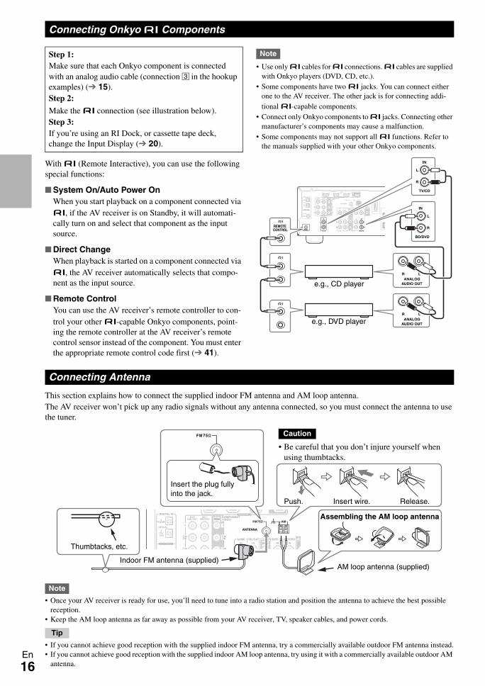
With u (Remote Interactive), you can use the following special functions:
System On/Auto Power OnWhen you start playback on a component connected via u, if the AV receiver is on Standby, it will automati-cally turn on and select that component as the input source.
Direct ChangeWhen playback is started on a component connected via u, the AV receiver automatically selects that compo-nent as the input source.
Remote ControlYou can use the AV receiver’s remote controller to con-trol your other u-capable Onkyo components, point-ing the remote controller at the AV receiver’s remote control sensor instead of the component. You must enter the appropriate remote control code first ( 41).
Note
• Use only u cables for u connections. u cables are supplied with Onkyo players (DVD, CD, etc.).
• Some components have two u jacks. You can connect either one to the AV receiver. The other jack is for connecting addi-tional u-capable components.
• Connect only Onkyo components to u jacks. Connecting other manufacturer’s components may cause a malfunction.
• Some components may not support all u functions. Refer to the manuals supplied with your other Onkyo components.
This section explains how to connect the supplied indoor FM antenna and AM loop antenna.The AV receiver won’t pick up any radio signals without any antenna connected, so you must connect the antenna to use the tuner.
Note
• Once your AV receiver is ready for use, you’ll need to tune into a radio station and position the antenna to achieve the best possible reception.
• Keep the AM loop antenna as far away as possible from your AV receiver, TV, speaker cables, and power cords.
Tip
• If you cannot achieve good reception with the supplied indoor FM antenna, try a commercially available outdoor FM antenna instead.• If you cannot achieve good reception with the supplied indoor AM loop antenna, try using it with a commercially available outdoor AM
antenna.
Connecting Onkyo u Components
Step 1:Make sure that each Onkyo component is connected with an analog audio cable (connection C in the hookup examples) ( 15).Step 2:
Make the u connection (see illustration below).Step 3:If you’re using an RI Dock, or cassette tape deck, change the Input Display ( 20).
LR
IN
BD/DVD
L
R
IN
TV/CD
L
R
REMOTE CONTROL
ANALOGAUDIO OUT
LRANALOG
AUDIO OUT
e.g., CD player
e.g., DVD player
Connecting Antenna
Thumbtacks, etc.
Insert the plug fully into the jack.
Push. Insert wire. Release.
Assembling the AM loop antenna
Indoor FM antenna (supplied)AM loop antenna (supplied)
Caution
• Be careful that you don’t injure yourself when using thumbtacks.
17En
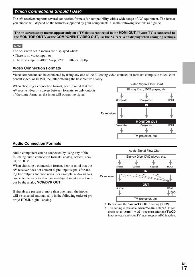
The AV receiver supports several connection formats for compatibility with a wide range of AV equipment. The format you choose will depend on the formats supported by your components. Use the following sections as a guide.
Note
The on-screen setup menus are displayed when:• There is no video input, or• The video input is 480p, 576p, 720p, 1080i, or 1080p.
Video Connection Formats
Video component can be connected by using any one of the following video connection formats: composite video, com-ponent video, or HDMI, the latter offering the best picture quality.
When choosing a connection format, bear in mind that the AV receiver doesn’t convert between formats, so only outputs of the same format as the input will output the signal.
Audio Connection Formats
Audio component can be connected by using any of the following audio connection formats: analog, optical, coax-ial, or HDMI.When choosing a connection format, bear in mind that the AV receiver does not convert digital input signals for ana-log line outputs and vice versa. For example, audio signals connected to an optical or coaxial digital input are not out-put by the analog VCR/DVR OUT.
If signals are present at more than one input, the inputs will be selected automatically in the following order of pri-ority: HDMI, digital, analog.
Which Connections Should I Use?
The on-screen setup menus appear only on a TV that is connected to the HDMI OUT. If your TV is connected to the MONITOR OUT V or the COMPONENT VIDEO OUT, use the AV receiver’s display when changing settings.
IN
MONITOR OUT
Blu-ray Disc, DVD player, etc.
AV receiver
TV, projector, etc.
Composite
Composite
Component
Component
Video Signal Flow Chart
HDMI
HDMI
IN
OUT
*1 *2
*1*1
*1
Blu-ray Disc, DVD player, etc.
AV receiver
TV, projector, etc.
HDMICoaxial Analog
Audio Signal Flow Chart
HDMI Analog
Optical
*1 Depends on the “Audio TV OUT” setting ( 32).*2 This setting is available, when “Audio Return Ch” set-
ting is set to “Auto” ( 33), you must select the TV/CD input selector and your TV must support ARC function.
18En
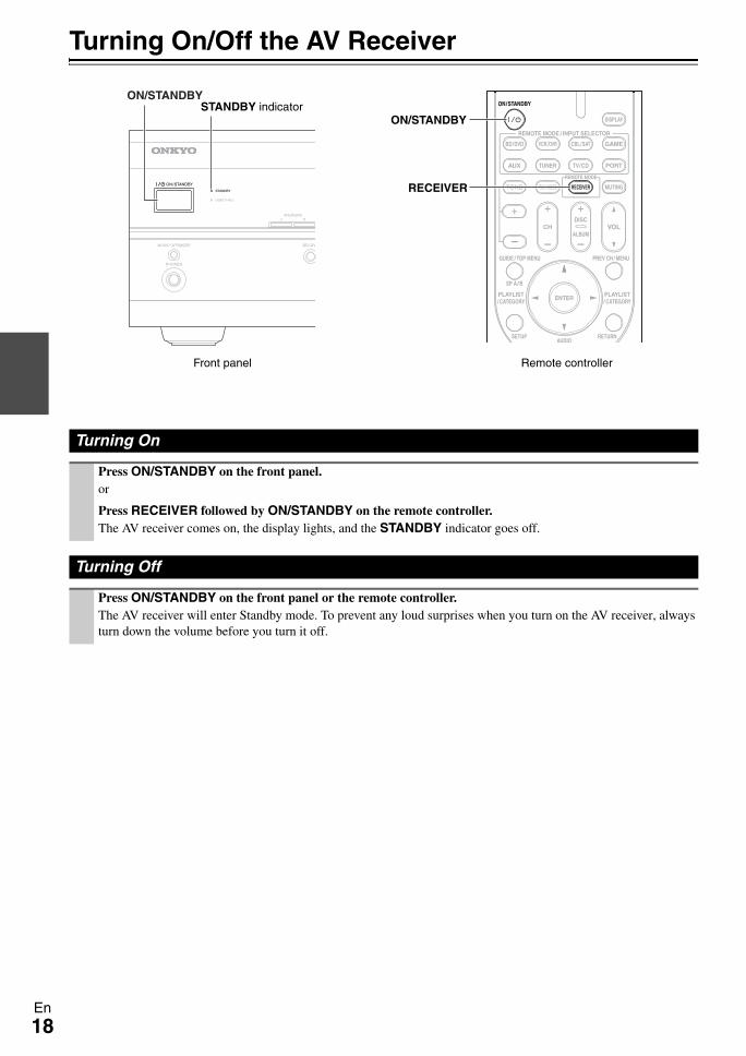
Turning On/Off the AV Receiver
Turning On
Press ON/STANDBY on the front panel. or
Press RECEIVER followed by ON/STANDBY on the remote controller.The AV receiver comes on, the display lights, and the STANDBY indicator goes off.
Turning Off
Press ON/STANDBY on the front panel or the remote controller.The AV receiver will enter Standby mode. To prevent any loud surprises when you turn on the AV receiver, always turn down the volume before you turn it off.
ON/STANDBY
ON/STANDBY
RECEIVER
STANDBY indicator
Front panel Remote controller
19En
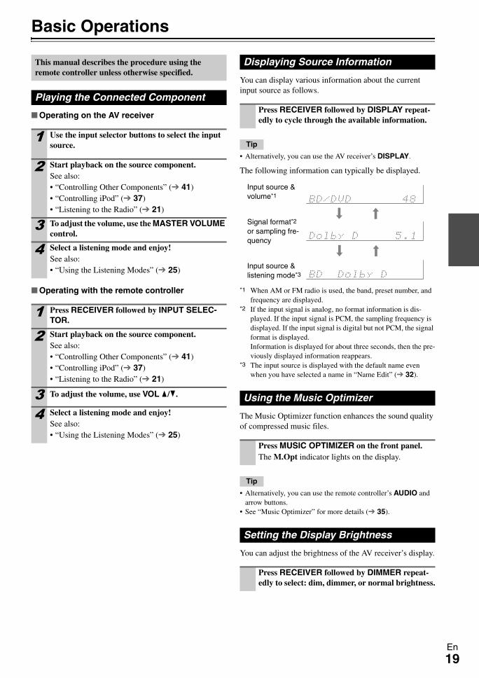
Basic Operations
Operating on the AV receiver
Operating with the remote controller
You can display various information about the current input source as follows.
Tip
• Alternatively, you can use the AV receiver’s DISPLAY.
The following information can typically be displayed.
*1 When AM or FM radio is used, the band, preset number, and frequency are displayed.
*2 If the input signal is analog, no format information is dis-played. If the input signal is PCM, the sampling frequency is displayed. If the input signal is digital but not PCM, the signal format is displayed. Information is displayed for about three seconds, then the pre-viously displayed information reappears.
*3 The input source is displayed with the default name even when you have selected a name in “Name Edit” ( 32).
The Music Optimizer function enhances the sound quality of compressed music files.
Tip
• Alternatively, you can use the remote controller’s AUDIO and arrow buttons.
• See “Music Optimizer” for more details ( 35).
You can adjust the brightness of the AV receiver’s display.
This manual describes the procedure using the remote controller unless otherwise specified.
Playing the Connected Component
1 Use the input selector buttons to select the input source.
2 Start playback on the source component.See also:• “Controlling Other Components” ( 41)• “Controlling iPod” ( 37)• “Listening to the Radio” ( 21)
3 To adjust the volume, use the MASTER VOLUME control.
4 Select a listening mode and enjoy!See also:• “Using the Listening Modes” ( 25)
1 Press RECEIVER followed by INPUT SELEC-TOR.
2 Start playback on the source component.See also:• “Controlling Other Components” ( 41)• “Controlling iPod” ( 37)• “Listening to the Radio” ( 21)
3 To adjust the volume, use VOL q/w.
4 Select a listening mode and enjoy!See also:• “Using the Listening Modes” ( 25)
Displaying Source Information
Press RECEIVER followed by DISPLAY repeat-edly to cycle through the available information.
Using the Music Optimizer
Press MUSIC OPTIMIZER on the front panel.The M.Opt indicator lights on the display.
Setting the Display Brightness
Press RECEIVER followed by DIMMER repeat-edly to select: dim, dimmer, or normal brightness.
Input source & volume*1
Signal format*2 or sampling fre-quency
Input source & listening mode*3
20En
You can temporarily mute the output of the AV receiver.
Tip
• To unmute, press MUTING again or adjust the volume.• The Mute function is cancelled when the AV receiver is set to
Standby.
With the sleep timer, you can set the AV receiver to turn off automatically after a specified period.
Tip
• If you need to cancel the sleep timer, press SLEEP repeatedly until the SLEEP indicator goes off.
• To check the time remaining until the AV receiver sleeps, press SLEEP. Note that if you press SLEEP while the sleep time is being displayed, you’ll shorten the sleep time by 10 minutes.
Note
• Always turn down the volume before connecting your head-phones.
• While the headphones plug is inserted in the PHONES jack, the speakers are turned off.
• When you connect a pair of headphones, the listening mode is set to Stereo, unless it’s already set to Stereo, Mono, or Direct.
• The listening modes cannot be selected while a pair of head-phones is connected.
When you connect an u-capable Onkyo component, you must configure the input display so that u can work properly.This setting can be done only from the front panel.
Note
• DOCK can be selected for the TV/CD, GAME or VCR/DVR input selector, but not at the same time.
• Enter the appropriate remote control code before using the remote controller for the first time ( 41).
You can use two sets of front speakers with the AV receiver: Speakers A for up to 5.1-channel playback in your main listening room and Speakers B for 2-channel stereo playback in another room.
Note
• While Speakers B is on, channels are reduced to 2.1 in the main room ( 10).
Tip
• Alternatively, you can use the AV receiver’s SPEAKERS A and B.
Muting the AV Receiver
Press RECEIVER followed by MUTING.The output is muted and the MUTING indicator flashes on the display.
Using the Sleep Timer
Press RECEIVER followed by SLEEP repeatedly to select the required sleep time.The sleep time can be set from 90 to 10 minutes in 10 minute steps.The SLEEP indicator lights on the display when the sleep timer has been set. The specified sleep time appears on the display for about five seconds, then the previous display reappears.
Using Headphones
Connect a pair of stereo headphones with a stan-dard plug (6.3 mm) to the PHONES jack.
Changing the Input Display
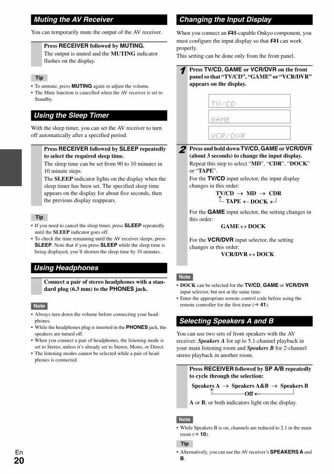
1 Press TV/CD, GAME or VCR/DVR on the front panel so that “TV/CD”, “GAME” or “VCR/DVR” appears on the display.
2 Press and hold down TV/CD, GAME or VCR/DVR (about 3 seconds) to change the input display.Repeat this step to select “MD”, “CDR”, “DOCK” or “TAPE”.For the TV/CD input selector, the input display changes in this order:
For the GAME input selector, the setting changes in this order:
For the VCR/DVR input selector, the setting changes in this order:
Selecting Speakers A and B
Press RECEIVER followed by SP A/B repeatedly to cycle through the selection:
A or B, or both indicators light on the display.
TV/CD → MD → CDRDOCK→
→ TAPE →
GAME ↔ DOCK
VCR/DVR ↔ DOCK
Speakers A → Speakers A&B → Speakers B
→ Off ←
21En
Listening to the Radio
With the built-in tuner you can enjoy AM and FM radio stations. You can store your favorite stations as presets for quick selection.
Listening to the Radio
Tuning into Radio Stations
Auto tuning mode
When tuned into a station, the TUNED indicator lights. When tuned into a stereo FM station, the FM STEREO indicator lights on the display, as shown.
Tip
• Alternatively, you can use the remote controller’s TUN MODE and arrow buttons.
Manual tuning mode
This model changes AM frequency in 9 or 10 kHz steps.In manual tuning mode, FM stations will be in mono.
Tuning into weak FM stereo stationsIf the signal from a stereo FM station is weak, it may beimpossible to get good reception. In this case, switch to manual tuning mode and listen to the station in mono.
Tip
• Alternatively, you can use the remote controller’s TUN MODE and arrow buttons.
Tuning into stations by frequencyYou can tune into AM and FM stations directly by enter-ing the appropriate frequency.
This section describes the procedure using the but-tons on the front panel unless otherwise specified.
Using the Tuner
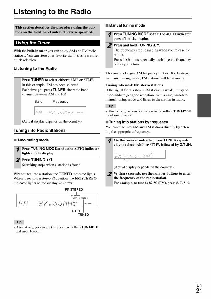
Press TUNER to select either “AM” or “FM”.In this example, FM has been selected.Each time you press TUNER, the radio band changes between AM and FM.
(Actual display depends on the country.)
1 Press TUNING MODE so that the AUTO indicator lights on the display.
2 Press TUNING q/w.Searching stops when a station is found.
Band Frequency
FM STEREO
AUTOTUNED
1 Press TUNING MODE so that the AUTO indicator goes off on the display.
2 Press and hold TUNING q/w.The frequency stops changing when you release the button.Press the buttons repeatedly to change the frequency one step at a time.
1 On the remote controller, press TUNER repeat-edly to select “AM” or “FM”, followed by D.TUN.
(Actual display depends on the country.)
2 Within 8 seconds, use the number buttons to enter the frequency of the radio station.For example, to tune to 87.50 (FM), press 8, 7, 5, 0.
22En
You can store a combination of up to 40 of your favorite FM/AM radio stations as presets.
Selecting Presets
Tip
• You can also use the remote controller’s number buttons to select a preset directly.
Deleting Presets
When tuned into an RDS station, the RDS indicator lights.
What is RDS?
RDS stands for Radio Data System and is a method of transmitting data in FM radio signals. It was developed by the European Broadcasting Union (EBU) and is available in most European countries. Many FM stations use it these days. In addition to displaying text information, RDS can also help you find radio stations by type (e.g., news, sport, rock, etc.).The AV receiver supports four types of RDS information:
PS (Program Service)When tuned to an RDS station that’s broadcasting PS information, the station’s name will be displayed. Press-ing DISPLAY will display the frequency for 3 seconds.
RT (Radio Text)When tuned to an RDS station that’s broadcasting text information, the text will be shown on the display as described in the next section.
PTY (Program Type)This allows you to search for RDS radio stations by type ( 23).
TP (Traffic Program)This allows you to search for RDS radio stations that broadcast traffic information ( 23).
Note
• In some cases, the text characters displayed on the AV receiver may not be identical to those broadcast by the radio station. Also, unexpected characters may be displayed when unsupported characters are received. This is not a malfunction.
• If the signal from an RDS station is weak, RDS data may be displayed intermittently or not at all.
When tuned to an RDS station that’s broadcasting text information, the text can be displayed.
Displaying Radio Text (RT)
Note
• The message “Waiting” may appear while the AV receiver waits for the RT information.
• If the message “No Text Data” appears on the display, no RT information is available.
Presetting FM/AM Stations
1 Tune into the FM/AM station that you want to store as a preset.See the previous section.
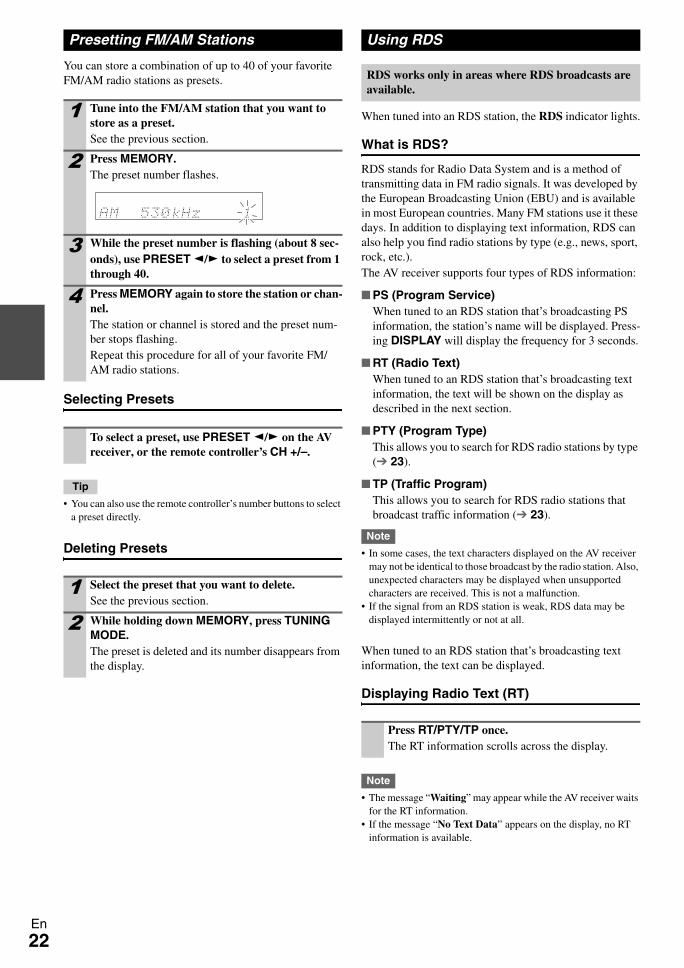
2 Press MEMORY.The preset number flashes.
3 While the preset number is flashing (about 8 sec-onds), use PRESET e/r to select a preset from 1 through 40.
4 Press MEMORY again to store the station or chan-nel.The station or channel is stored and the preset num-ber stops flashing.Repeat this procedure for all of your favorite FM/AM radio stations.
To select a preset, use PRESET e/r on the AV receiver, or the remote controller’s CH +/–.
1 Select the preset that you want to delete.See the previous section.
2 While holding down MEMORY, press TUNING MODE.The preset is deleted and its number disappears from the display.
Using RDS
RDS works only in areas where RDS broadcasts are available.
Press RT/PTY/TP once.The RT information scrolls across the display.
23En
Finding Stations by Type (PTY)
You can search for radio stations by type.
Listening to Traffic News (TP)
You can search for stations that broadcast traffic news.
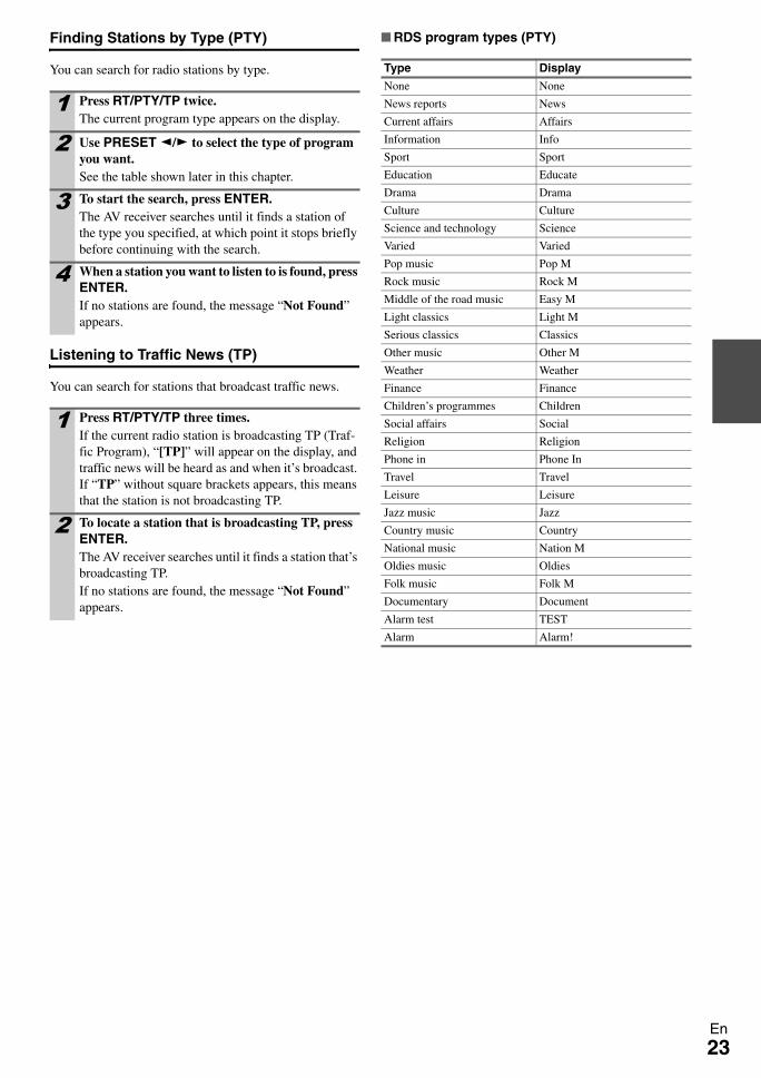
RDS program types (PTY)
1 Press RT/PTY/TP twice.The current program type appears on the display.
2 Use PRESET e/r to select the type of program you want.See the table shown later in this chapter.
3 To start the search, press ENTER.The AV receiver searches until it finds a station of the type you specified, at which point it stops briefly before continuing with the search.
4 When a station you want to listen to is found, press ENTER.If no stations are found, the message “Not Found” appears.
1 Press RT/PTY/TP three times.If the current radio station is broadcasting TP (Traf-fic Program), “[TP]” will appear on the display, and traffic news will be heard as and when it’s broadcast. If “TP” without square brackets appears, this means that the station is not broadcasting TP.
2 To locate a station that is broadcasting TP, press ENTER.The AV receiver searches until it finds a station that’s broadcasting TP.If no stations are found, the message “Not Found” appears.
Type Display
None None
News reports News
Current affairs Affairs
Information Info
Sport Sport
Education Educate
Drama Drama
Culture Culture
Science and technology Science
Varied Varied
Pop music Pop M
Rock music Rock M
Middle of the road music Easy M
Light classics Light M
Serious classics Classics
Other music Other M
Weather Weather
Finance Finance
Children’s programmes Children
Social affairs Social
Religion Religion
Phone in Phone In
Travel Travel
Leisure Leisure
Jazz music Jazz
Country music Country
National music Nation M
Oldies music Oldies
Folk music Folk M
Documentary Document
Alarm test TEST
Alarm Alarm!

24En
RecordingThis section explains how to record the selected input source to a component with recording capability, and how to record audio and video from different sources.
Connecting a Recording Component
Note
• The AV receiver must be turned on for recording. Recording is not possible while it’s in Standby mode.
• If you want to record directly from your TV or playback VCR to the recording VCR without going through the AV receiver, con-nect the TV/VCR’s audio and video outputs directly to the recording VCR’s audio and video inputs. See the manuals sup-plied with your TV and VCR for details.
• Video signals connected to composite video inputs can be recorded only via composite video outputs. If your TV/VCR is connected to a composite video input, the recording VCR must be connected to a composite video output.
• The surround sound and DSP listening modes cannot be recorded.
• Copy-protected Blu-ray discs and DVDs cannot be recorded.• Sources connected to a digital input cannot be recorded. Only
analog inputs can be recorded.• DTS signals will be recorded as noise, so don’t attempt analog
recording of DTS CDs or LDs.
AV Recording
Audio sources can be recorded to a recorder (e.g., cassette deck, CDR, MD) connected to the VCR/DVR OUT jacks. Video sources can be recorded to a video recorder (e.g., VCR, DVD recorder) connected to the VCR/DVR OUT jack.
Recording Separate AV Sources
Here you can record audio and video from completely separate sources, allowing you to overdub audio onto your video recordings. This function takes advantage of the fact that when an audio-only input source (TV/CD) is selected, the video input source remains unchanged.In the following example, audio from the CD player con-nected to the TV/CD IN and video from the camcorder connected to the BD/DVD IN are recorded by the VCR connected to the VCR/DVR OUT jacks.
1 Use the input selector buttons to select the source that you want to record.You can watch the source while recording. The AV receiver’s MASTER VOLUME control has no effect on recording.
2 On your recorder, start recording.
3 On the source component, start playback.If you select another input source during recording, that input source will be recorded.
AUDIOIN
L R
VIDEOIN
Cassette, CDR, MD, etc.
VCR, DVD recorder
1 Prepare the camcorder and CD player for play-back.
2 Prepare the VCR for recording.
3 Press BD/DVD input selector.
4 Press TV/CD input selector.This selects the CD player as the audio source, but leaves the camcorder as the video source.
5 Start recording on the VCR and start playback on the camcorder and CD player.The video from the camcorder and the audio from the CD player are recorded by the VCR.
Camcorder
VCRCD player
: Video signal: Audio signal
25En
Using the Listening Modes
See “About Listening Modes” for detailed information about the listening modes ( 25).
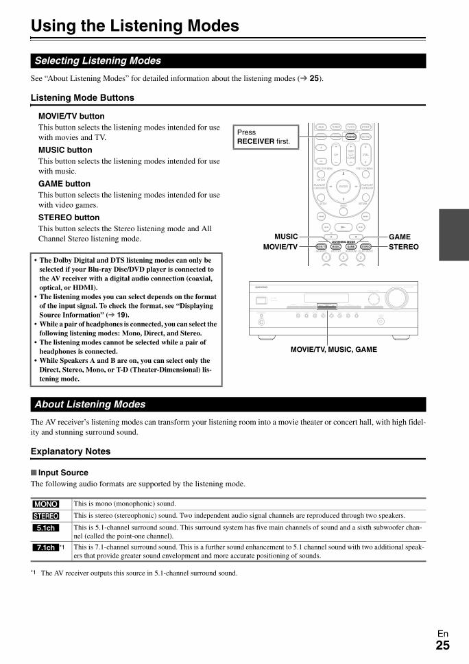
Listening Mode Buttons
MOVIE/TV buttonThis button selects the listening modes intended for use with movies and TV.
MUSIC buttonThis button selects the listening modes intended for use with music.
GAME buttonThis button selects the listening modes intended for use with video games.
STEREO buttonThis button selects the Stereo listening mode and All Channel Stereo listening mode.
The AV receiver’s listening modes can transform your listening room into a movie theater or concert hall, with high fidel-ity and stunning surround sound.
Explanatory Notes
Input SourceThe following audio formats are supported by the listening mode.
*1 The AV receiver outputs this source in 5.1-channel surround sound.
Selecting Listening Modes
• The Dolby Digital and DTS listening modes can only be selected if your Blu-ray Disc/DVD player is connected to the AV receiver with a digital audio connection (coaxial, optical, or HDMI).
• The listening modes you can select depends on the format of the input signal. To check the format, see “Displaying Source Information” ( 19).
• While a pair of headphones is connected, you can select the following listening modes: Mono, Direct, and Stereo.
• The listening modes cannot be selected while a pair of headphones is connected.
• While Speakers A and B are on, you can select only the Direct, Stereo, Mono, or T-D (Theater-Dimensional) lis-tening mode.
GAMESTEREOMOVIE/TV
MUSIC
Press RECEIVER first.
MOVIE/TV, MUSIC, GAME
About Listening Modes
A This is mono (monophonic) sound.
S This is stereo (stereophonic) sound. Two independent audio signal channels are reproduced through two speakers.
D This is 5.1-channel surround sound. This surround system has five main channels of sound and a sixth subwoofer chan-nel (called the point-one channel).
F*1 This is 7.1-channel surround sound. This is a further sound enhancement to 5.1 channel sound with two additional speak-ers that provide greater sound envelopment and more accurate positioning of sounds.
26En
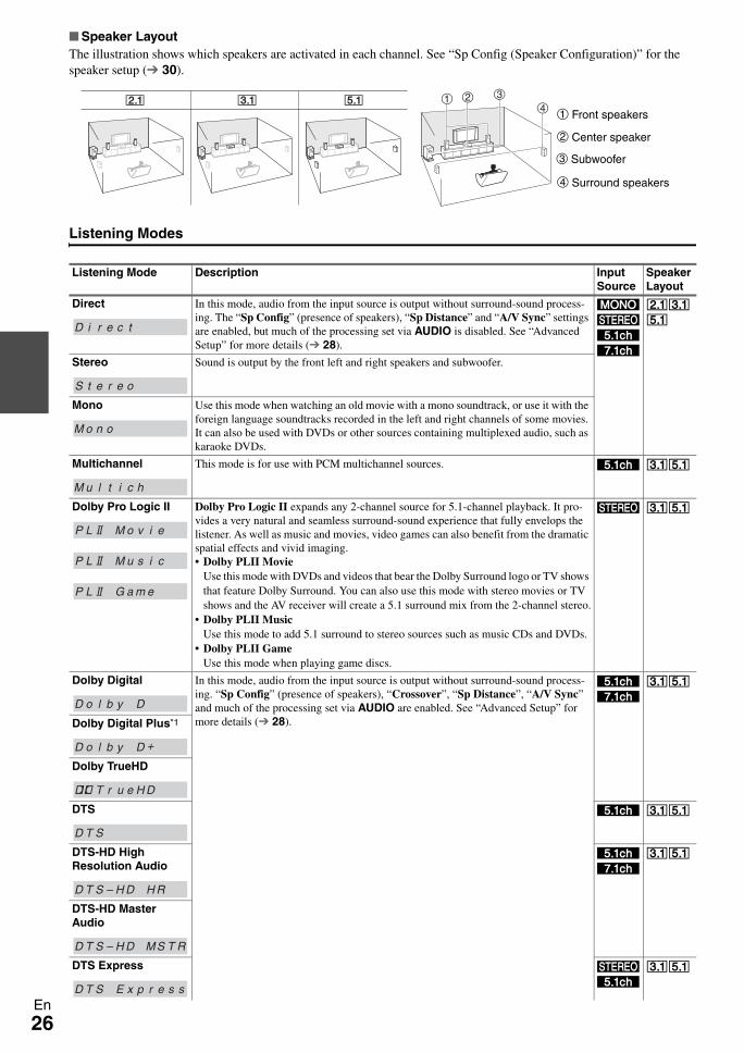
Speaker LayoutThe illustration shows which speakers are activated in each channel. See “Sp Config (Speaker Configuration)” for the speaker setup ( 30).
Listening Modes
Listening Mode Description Input Source
Speaker Layout
Direct In this mode, audio from the input source is output without surround-sound process-ing. The “Sp Config” (presence of speakers), “Sp Distance” and “A/V Sync” settings are enabled, but much of the processing set via AUDIO is disabled. See “Advanced Setup” for more details ( 28).
ASDF
ZXC
Stereo Sound is output by the front left and right speakers and subwoofer.
Mono Use this mode when watching an old movie with a mono soundtrack, or use it with the foreign language soundtracks recorded in the left and right channels of some movies. It can also be used with DVDs or other sources containing multiplexed audio, such as karaoke DVDs.
Multichannel This mode is for use with PCM multichannel sources. D XC
Dolby Pro Logic II Dolby Pro Logic II expands any 2-channel source for 5.1-channel playback. It pro-vides a very natural and seamless surround-sound experience that fully envelops the listener. As well as music and movies, video games can also benefit from the dramatic spatial effects and vivid imaging.• Dolby PLII Movie
Use this mode with DVDs and videos that bear the Dolby Surround logo or TV shows that feature Dolby Surround. You can also use this mode with stereo movies or TV shows and the AV receiver will create a 5.1 surround mix from the 2-channel stereo.
• Dolby PLII MusicUse this mode to add 5.1 surround to stereo sources such as music CDs and DVDs.
• Dolby PLII GameUse this mode when playing game discs.
S XC
Dolby Digital In this mode, audio from the input source is output without surround-sound process-ing. “Sp Config” (presence of speakers), “Crossover”, “Sp Distance”, “A/V Sync” and much of the processing set via AUDIO are enabled. See “Advanced Setup” for more details ( 28).
DF
XC
Dolby Digital Plus*1
Dolby TrueHD
DTS D XC
DTS-HD High Resolution Audio
DF
XC
DTS-HD Master Audio
DTS Express SD
XC
Z X C ba c
da Front speakers
c Subwoofer
b Center speaker
d Surround speakers
D i r e c t
S t e r e o
M o n o
M u l t i c h
P L M o v i e
P L M u s i c
P L G a m e
D o l b y D
D o l b y D +
T er u H D
D T S
D T S – H D H R
D T S – H D MS T R
D T S E x p r e s s
27En
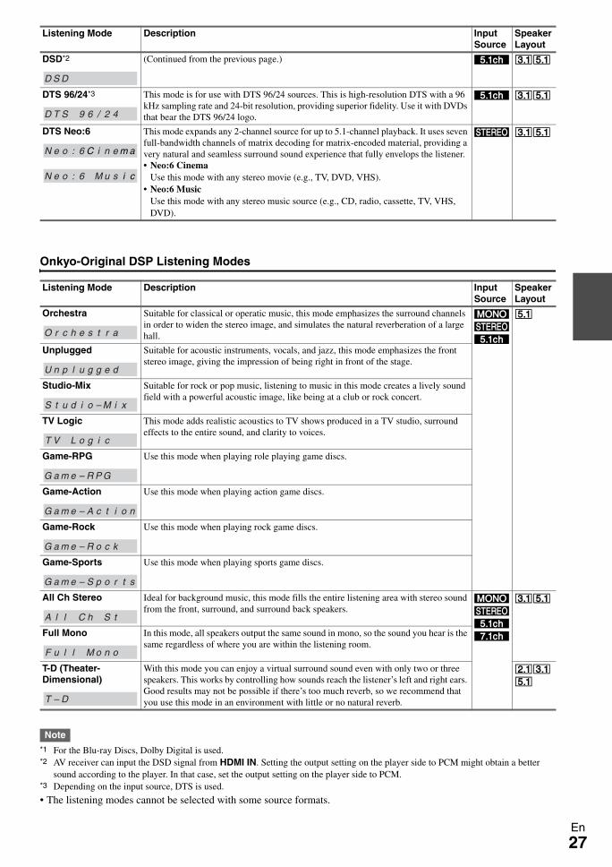
Onkyo-Original DSP Listening Modes
Note*1 For the Blu-ray Discs, Dolby Digital is used.*2 AV receiver can input the DSD signal from HDMI IN. Setting the output setting on the player side to PCM might obtain a better
sound according to the player. In that case, set the output setting on the player side to PCM. *3 Depending on the input source, DTS is used.
• The listening modes cannot be selected with some source formats.
DSD*2 (Continued from the previous page.) D XC
DTS 96/24*3 This mode is for use with DTS 96/24 sources. This is high-resolution DTS with a 96 kHz sampling rate and 24-bit resolution, providing superior fidelity. Use it with DVDs that bear the DTS 96/24 logo.
D XC
DTS Neo:6 This mode expands any 2-channel source for up to 5.1-channel playback. It uses seven full-bandwidth channels of matrix decoding for matrix-encoded material, providing a very natural and seamless surround sound experience that fully envelops the listener.• Neo:6 Cinema
Use this mode with any stereo movie (e.g., TV, DVD, VHS).• Neo:6 Music
Use this mode with any stereo music source (e.g., CD, radio, cassette, TV, VHS, DVD).
S XC
Listening Mode Description Input Source
Speaker Layout
Orchestra Suitable for classical or operatic music, this mode emphasizes the surround channels in order to widen the stereo image, and simulates the natural reverberation of a large hall.
ASD
C
Unplugged Suitable for acoustic instruments, vocals, and jazz, this mode emphasizes the front stereo image, giving the impression of being right in front of the stage.
Studio-Mix Suitable for rock or pop music, listening to music in this mode creates a lively sound field with a powerful acoustic image, like being at a club or rock concert.
TV Logic This mode adds realistic acoustics to TV shows produced in a TV studio, surround effects to the entire sound, and clarity to voices.
Game-RPG Use this mode when playing role playing game discs.
Game-Action Use this mode when playing action game discs.
Game-Rock Use this mode when playing rock game discs.
Game-Sports Use this mode when playing sports game discs.
All Ch Stereo Ideal for background music, this mode fills the entire listening area with stereo sound from the front, surround, and surround back speakers.
ASDF
XC
Full Mono In this mode, all speakers output the same sound in mono, so the sound you hear is the same regardless of where you are within the listening room.
T-D (Theater-Dimensional)
With this mode you can enjoy a virtual surround sound even with only two or three speakers. This works by controlling how sounds reach the listener’s left and right ears. Good results may not be possible if there’s too much reverb, so we recommend that you use this mode in an environment with little or no natural reverb.
ZXC
Listening Mode Description Input Source
Speaker Layout
D S D
D T S 9 6 / 2 4
N e o : 6N e o : 6 C i n e m a
N e o : 6 M u s i c
O r c h e s t r a
U n p l u g g e d
S t u d i o – M i x
T V L o g i c
G a m e – R P G
G a m e – A c t i o n
G a m e – R o c k
G a m e – S p o r t s
A l l C h S t
F u l l M o n o
T – D
28En
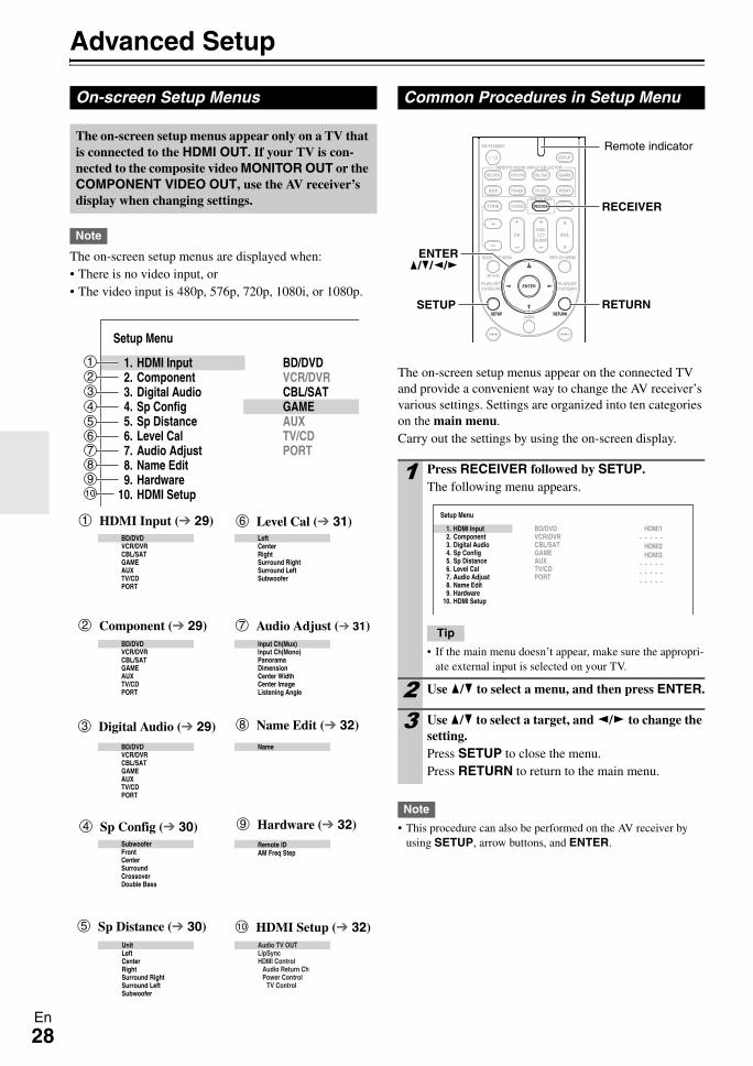
Advanced Setup
Note
The on-screen setup menus are displayed when:• There is no video input, or• The video input is 480p, 576p, 720p, 1080i, or 1080p.
The on-screen setup menus appear on the connected TV and provide a convenient way to change the AV receiver’s various settings. Settings are organized into ten categories on the main menu.Carry out the settings by using the on-screen display.
Note
• This procedure can also be performed on the AV receiver by using SETUP, arrow buttons, and ENTER.
On-screen Setup Menus
The on-screen setup menus appear only on a TV that is connected to the HDMI OUT. If your TV is con-nected to the composite video MONITOR OUT or the COMPONENT VIDEO OUT, use the AV receiver’s display when changing settings.
Setup Menu
BD/DVDVCR/DVRCBL/SATGAMEAUXTV/CDPORT
Remote IDAM Freq Step
Input Ch(Mux)Input Ch(Mono)PanoramaDimensionCenter WidthCenter ImageListening Angle
LeftCenterRightSurround RightSurround LeftSubwoofer
BD/DVDVCR/DVRCBL/SATGAMEAUXTV/CDPORT
BD/DVDVCR/DVRCBL/SATGAMEAUXTV/CDPORT
SubwooferFrontCenterSurroundCrossoverDouble Bass
UnitLeftCenterRightSurround RightSurround LeftSubwoofer
Name
Audio TV OUTLipSyncHDMI Control
Audio Return ChPower Control
TV Control
1. HDMI Input 2. Component 3. Digital Audio 4. Sp Config 5. Sp Distance 6. Level Cal 7. Audio Adjust 8. Name Edit 9. Hardware10. HDMI Setup
BD/DVDVCR/DVRCBL/SATGAMEAUXTV/CDPORT
abcdefghij
a HDMI Input ( 29)
b Component ( 29)
c Digital Audio ( 29)
d Sp Config ( 30)
e Sp Distance ( 30)
f Level Cal ( 31)
h Name Edit ( 32)
i Hardware ( 32)
j HDMI Setup ( 32)
g Audio Adjust ( 31)
Common Procedures in Setup Menu
1 Press RECEIVER followed by SETUP.The following menu appears.
Tip
• If the main menu doesn’t appear, make sure the appropri-ate external input is selected on your TV.
2 Use q/w to select a menu, and then press ENTER.
3 Use q/w to select a target, and e/r to change the setting.Press SETUP to close the menu.Press RETURN to return to the main menu.
RETURNSETUP
RECEIVER
ENTERq/w/e/r
Remote indicator
Setup Menu
1. HDMI Input 2. Component 3. Digital Audio 4. Sp Config 5. Sp Distance 6. Level Cal 7. Audio Adjust 8. Name Edit 9. Hardware10. HDMI Setup
BD/DVDVCR/DVRCBL/SATGAMEAUXTV/CDPORT
HDMI1- - - - -
HDMI2HDMI3
- - - - -- - - - -- - - - -
29En
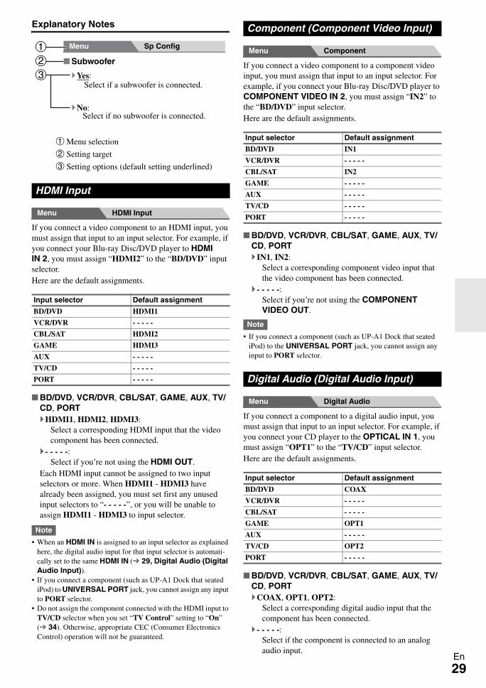
Explanatory Notes
Menu HDMI Input
If you connect a video component to an HDMI input, you must assign that input to an input selector. For example, if you connect your Blu-ray Disc/DVD player to HDMI IN 2, you must assign “HDMI2” to the “BD/DVD” input selector.Here are the default assignments.
BD/DVD, VCR/DVR, CBL/SAT, GAME, AUX, TV/CD, PORT
HDMI1, HDMI2, HDMI3:Select a corresponding HDMI input that the video component has been connected.
- - - - -:Select if you’re not using the HDMI OUT.
Each HDMI input cannot be assigned to two input selectors or more. When HDMI1 - HDMI3 have already been assigned, you must set first any unused input selectors to “- - - - -”, or you will be unable to assign HDMI1 - HDMI3 to input selector.
Note
• When an HDMI IN is assigned to an input selector as explained here, the digital audio input for that input selector is automati-cally set to the same HDMI IN ( 29, Digital Audio (Digital Audio Input)).
• If you connect a component (such as UP-A1 Dock that seated iPod) to UNIVERSAL PORT jack, you cannot assign any input to PORT selector.
• Do not assign the component connected with the HDMI input to TV/CD selector when you set “TV Control” setting to “On” ( 34). Otherwise, appropriate CEC (Consumer Electronics Control) operation will not be guaranteed.
Menu Component
If you connect a video component to a component video input, you must assign that input to an input selector. For example, if you connect your Blu-ray Disc/DVD player to COMPONENT VIDEO IN 2, you must assign “IN2” to the “BD/DVD” input selector. Here are the default assignments.
BD/DVD, VCR/DVR, CBL/SAT, GAME, AUX, TV/CD, PORT
IN1, IN2:Select a corresponding component video input that the video component has been connected.
- - - - -:Select if you’re not using the COMPONENT VIDEO OUT.
Note
• If you connect a component (such as UP-A1 Dock that seated iPod) to the UNIVERSAL PORT jack, you cannot assign any input to PORT selector.
Menu Digital Audio
If you connect a component to a digital audio input, you must assign that input to an input selector. For example, if you connect your CD player to the OPTICAL IN 1, you must assign “OPT1” to the “TV/CD” input selector. Here are the default assignments.
BD/DVD, VCR/DVR, CBL/SAT, GAME, AUX, TV/CD, PORT
COAX, OPT1, OPT2:Select a corresponding digital audio input that the component has been connected.
- - - - -:Select if the component is connected to an analog audio input.
HDMI Input
Input selector Default assignment
BD/DVD HDMI1
VCR/DVR - - - - -
CBL/SAT HDMI2
GAME HDMI3
AUX - - - - -
TV/CD - - - - -
PORT - - - - -
Subwoofer
Yes:
No:
Menu Sp Config
b
a
c
a Menu selection
b Setting target
c Setting options (default setting underlined)
Select if a subwoofer is connected.
Select if no subwoofer is connected.
Component (Component Video Input)
Input selector Default assignment
BD/DVD IN1
VCR/DVR - - - - -
CBL/SAT IN2
GAME - - - - -
AUX - - - - -
TV/CD - - - - -
PORT - - - - -
Digital Audio (Digital Audio Input)
Input selector Default assignment
BD/DVD COAX
VCR/DVR - - - - -
CBL/SAT - - - - -
GAME OPT1
AUX - - - - -
TV/CD OPT2
PORT - - - - -
30En
Note
• When an HDMI IN is assigned to an input selector in “HDMI Input” ( 29), this input assignment is automatically set to the same HDMI IN. And in addition to the usual inputs (e.g., COAX, etc.), you can also select HDMI inputs.
• Available sampling rate for PCM signals from a digital input (optical and coaxial) is 32/44.1/48/88.2/96 kHz/16, 20, 24 bit.
• If you connect a component (such as UP-A1 Dock that seated iPod) to the UNIVERSAL PORT jack, you cannot assign any input to PORT selector.
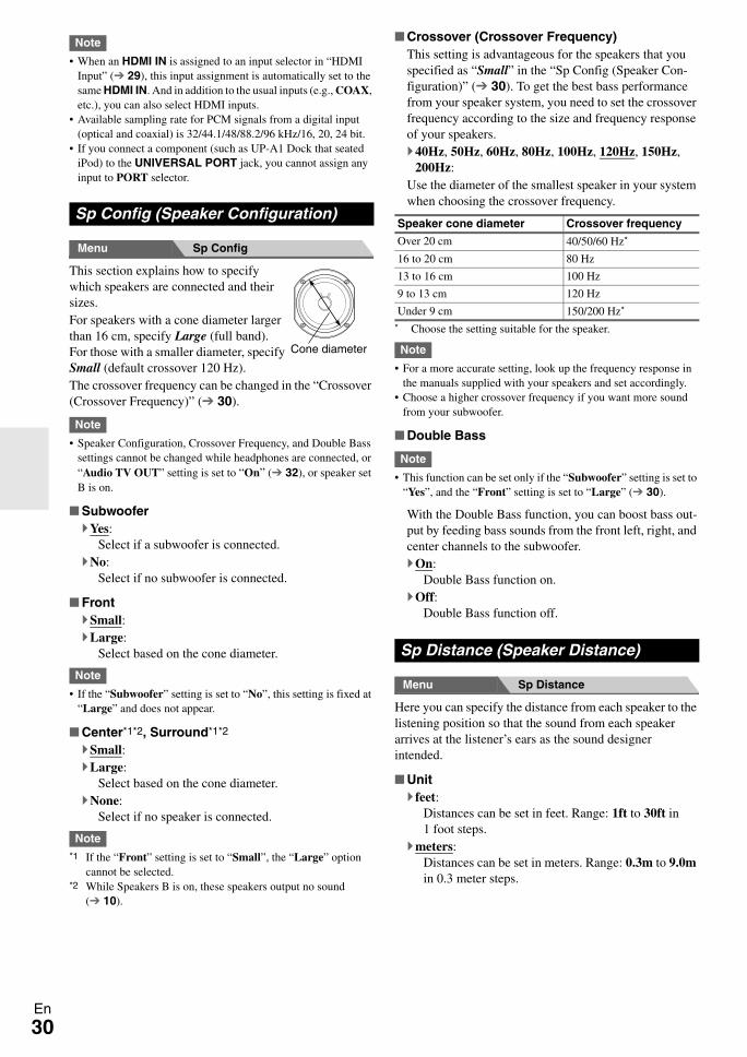
Menu Sp Config
This section explains how to specify which speakers are connected and their sizes.For speakers with a cone diameter larger than 16 cm, specify Large (full band). For those with a smaller diameter, specify Small (default crossover 120 Hz).The crossover frequency can be changed in the “Crossover (Crossover Frequency)” ( 30).
Note
• Speaker Configuration, Crossover Frequency, and Double Bass settings cannot be changed while headphones are connected, or “Audio TV OUT” setting is set to “On” ( 32), or speaker set B is on.
SubwooferYes:
Select if a subwoofer is connected.No:
Select if no subwoofer is connected.
FrontSmall:Large:
Select based on the cone diameter.
Note
• If the “Subwoofer” setting is set to “No”, this setting is fixed at “Large” and does not appear.
Center*1*2, Surround*1*2
Small:Large:
Select based on the cone diameter.None:
Select if no speaker is connected.
Note*1 If the “Front” setting is set to “Small”, the “Large” option
cannot be selected.*2 While Speakers B is on, these speakers output no sound
( 10).
Crossover (Crossover Frequency)This setting is advantageous for the speakers that you specified as “Small” in the “Sp Config (Speaker Con-figuration)” ( 30). To get the best bass performance from your speaker system, you need to set the crossover frequency according to the size and frequency response of your speakers.
40Hz, 50Hz, 60Hz, 80Hz, 100Hz, 120Hz, 150Hz, 200Hz:
Use the diameter of the smallest speaker in your system when choosing the crossover frequency.
* Choose the setting suitable for the speaker.
Note
• For a more accurate setting, look up the frequency response in the manuals supplied with your speakers and set accordingly.
• Choose a higher crossover frequency if you want more sound from your subwoofer.
Double Bass
Note
• This function can be set only if the “Subwoofer” setting is set to “Yes”, and the “Front” setting is set to “Large” ( 30).
With the Double Bass function, you can boost bass out-put by feeding bass sounds from the front left, right, and center channels to the subwoofer.
On:Double Bass function on.
Off:Double Bass function off.
Menu Sp Distance
Here you can specify the distance from each speaker to the listening position so that the sound from each speaker arrives at the listener’s ears as the sound designer intended.
Unitfeet:
Distances can be set in feet. Range: 1ft to 30ft in 1 foot steps.
meters:Distances can be set in meters. Range: 0.3m to 9.0m in 0.3 meter steps.
Sp Config (Speaker Configuration)
Cone diameter
Speaker cone diameter Crossover frequency
Over 20 cm 40/50/60 Hz*
16 to 20 cm 80 Hz
13 to 16 cm 100 Hz
9 to 13 cm 120 Hz
Under 9 cm 150/200 Hz*
Sp Distance (Speaker Distance)
31En
Left, Center, Right, Surround Right, Surround Left, Subwoofer
Specify the distance from the each speaker to your lis-tening position.
Note
• The speaker distance setting cannot be changed while a pair of headphones is connected, or “Audio TV OUT” setting is set to “On” ( 32), or Speakers B is on.
• Speakers that you set to “No” or “None” in the “Sp Config (Speaker Configuration)” ( 30) cannot be selected.
• The Center, Right, and Subwoofer distances can be set up to 1.5 m more or less than the Left distance. For example, if the Left distance is set to 6 m, the Center, Right, and Subwoofer dis-tances can be set between 4.5 and 7.5 m.
• The Surround distances can be set up to 1.5 m more or 4.5 m less than the Left distance. For example, if the Left distance is set to 6 m, the SurrRight and SurrLeft distances can be set between 1.5 and 7.5 m.
Menu Level Cal
Here you can adjust the level of each speaker with the built-in test tone so that the volume of each speaker is the same at the listening position.
Left, Center*1, Right, Surround Right, Surround Left
–12 dB to 0 dB to +12 dB in 1 dB step.
Subwoofer*1
–15 dB to 0 dB to +12 dB in 1 dB step.
Note
• Speakers that you set to “No” or “None” in the “Sp Config (Speaker Configuration)” ( 30) cannot be selected.
• The speakers cannot be calibrated while a pair of headphones is connected, Speakers B is on, or “Audio TV OUT” setting is set to “On” ( 32), or the AV receiver is muted.
*1 For the center speaker and subwoofer, the level settings made by using AUDIO are saved.
Tip
• If you’re using a handheld sound level meter, adjust the level of each speaker so that it reads 75 dB SPL at the listening position, measured with C-weighting and slow reading.
Menu Audio Adjust
With the Audio Adjust functions and settings, you can adjust the sound and listening modes as you like.
Multiplex/Mono Settings
MultiplexThis setting determines which channel of a stereo multi-plex source is output. Use it to select audio channels or languages with multiplex sources, multilingual TV broad-casts, and so on.
Input Ch(Mux)Main:
The main channel is output.Sub:
The sub channel is output.M/S:
Both the main and sub channels are output.MonoThis setting specifies the channel to be used for playing any 2-channel digital source such as Dolby Digital, or 2-channel analog/PCM source in the Mono listening mode.
Input Ch(Mono)L+R:
Both the left and right channels are output.Left:
Only the left channel is output.Right:
Only the right channel is output.
Dolby Settings
PLII Music (2ch Input)These settings apply to only 2-channel stereo sources.
PanoramaOn:
Panorama function on.Off:
Panorama function off.With this setting, you can broaden the width of the front stereo image when using the Dolby Pro Logic II Music listening mode.
Dimension–3 to 0 to +3
With this setting, you can move the sound field forward or backward when using the Dolby Pro Logic II Music listening mode. Higher settings move the sound field backward. Lower settings move it forward.If the stereo image feels too wide, or there’s too much surround sound, move the sound field forward to improve the balance. Conversely, if the stereo image feels like it’s in mono, or there’s not enough surround sound, move it backward.
Center Width0 to 3 to 7
With this setting, you can adjust the width of the sound from the center speaker when using the Dolby Pro Logic II Music listening mode. Normally, if you’re using a center speaker, the center channel sound is out-put by only the center speaker. (If you’re not using a center speaker, the center channel sound will be distrib-uted to the front left and right speakers to create a phan-tom center). This setting controls the front left, right, and center mix, allowing you to adjust the weight of the center channel sound.
Level Cal (Level Calibration)
Audio Adjust
32En
DTS Setting
Neo:6 Music
Center Image0 to 2 to 5
With this setting, you can specify by how much the front left and right channel output is attenuated in order to create the center channel. Setting a value “0” in the middle is set to hear a sound. Sound is spread in left and right (the outside) so that the set value is made big. Please adjust by liking.
Theater-Dimensional Setting
Listening AngleWide:
Select if the listening angle is 40 degrees.Narrow:
Select if the listening angle is 20 degrees.With this setting, you can optimize the Theater-Dimen-sional listening mode by specifying the angle of the front left and right speakers relative to the listening position. Ideally, the front left and right speakers should be equidistant from the listening position and at an angle close to one of the two available settings.
Menu Name Edit
You can enter a preset name for each individual input selector for easy identification. When entered, the preset name will appear on the display.
Name- - -, Blu-ray, DVD, HD DVD, VCR, DVR, Tivo, CableSTB, SAT STB, PS3, Wii, Xbox, PC, TV, CD, TAPE, iPod:
To reset to the default, select “- - -”.
Note
• Can not set the input selector by the same name.• This menu cannot be used for the TUNER input selector.
Menu Hardware
Remote Control Settings
Remote ID1, 2, or 3
When several Onkyo components are used in the same room, their remote ID codes may overlap. To differenti-ate the AV receiver from the other components, you can change its remote ID from “1”, to “2” or “3”.
Note
• If you do change the AV receiver’s remote ID, be sure to change the remote controller to the same ID (see below), otherwise, you won’t be able to control it with the remote controller.
Changing the Remote Controller’s ID
AM Frequency Setup Settings
For AM tuning to work properly, you must specify the AM frequency step used in your area. Note that when this setting is changed, all radio presets will be deleted.
AM Freq Step10kHz:
Select if 10 kHz steps are used in your area.9kHz:
Select if 9 kHz steps are used in your area.
Menu HDMI Setup
Audio TV OUTOff:
HDMI audio is not output.On:
HDMI audio is output.This preference determines whether audio received at the HDMI IN is output by the HDMI OUT. You may want to turn this preference on if your TV is connected to the HDMI OUT and you want to listen to the audio from a component that’s connected to an HDMI IN, through your TV’s speakers. Normally, this should be set to “Off”.
Name Edit
PreparationPress the input selector buttons to select an input source.
20°/40°
Front left speaker
Front right speaker
Hardware
1 While holding down RECEIVER, press and hold down SETUP until the remote indicator lights (about 3 seconds) ( 28).
2 Use the number buttons to enter ID 1, 2, or 3.The remote indicator flashes twice.
HDMI Setup
33En
Note
• If “On” is selected and the signal can be output by the TV, the AV receiver will output no sound through its speakers.
• If “On” is selected, “TV Sp On” appears on the display by pressing DISPLAY.
• When “TV Control” is set to “On”, this setting is fixed to “Auto”.
• With some TVs and input signals, no sound may be output even when this setting is set to “On”.
• When the “Audio TV OUT” setting is set to “On”, or “TV Con-trol” is set to “On” and you’re listening through your TV’s speakers ( 14), if you turn up the AV receiver’s volume con-trol, the sound will be output by the AV receiver’s front left and right speakers. To stop the AV receiver’s speakers producing sound, change the settings, change your TV’s settings, or turn down the AV receiver’s volume.
LipSyncDisable:
HDMI lip sync disabled.Enable:
HDMI lip sync enabled.The AV receiver can be set to automatically correct any delay between the video and the audio, based on the data from the connected monitor.
Note
• This function works only if your HDMI-compatible TV supports HDMI Lip Sync.
• You can check the amount of delay being applied by the HDMI Lip Sync function on the A/V Sync screen.
HDMI Control (RIHD)Off:p disabled.
On:p enabled.
This function allows p-compatible components connected via HDMI to be controlled with the AV receiver ( 49 to 51).
Note
• When set to “On” and close the menu, the name of connected p-compatible components and “RIHD On” are dis-played on the AV receiver.“Search…” → “(name)” → “RIHD On”When the AV receiver cannot receive the name of the compo-nent, it is displayed as “Player*” or “Recorder*”, etc (“*” means the number of two or more component).When set to “Off” and close the menu, “RIHD Off” are dis-played on the AV receiver.“Disconnect” → “RIHD Off”
• When an p-compatible component is connected to the AV receiver via the HDMI cable, the name of the connected component is displayed on the AV receiver display. For example, while you are watching TV broadcasting, if you operate a Blu-ray Disc/DVD player (being powered on) by the remote control of the AV receiver, the name of the Blu-ray Disc/DVD player is displayed on the AV receiver.
• Set to “Off” when a connected piece of equipment is not com-patible or it is unclear whether the equipment is compatible or not.
• If movement is unnatural when set to “On”, change the setting to “Off”.
• Refer to the connected component’s instruction manual for details.
Audio Return Ch (ARC)Off:
Select “Off” if you don’t want to use audio return channel (ARC) function.
Auto:The audio signal from your TV tuner can be sent to the HDMI OUT of the AV receiver.
Audio return channel (ARC) function enables an HDMI 1.4 capable TV to send the audio stream to the HDMI OUT of the AV receiver. To use this function, you must select the TV/CD input selector and your TV must support ARC function.
Note
• The “Audio Return Ch” setting can be set only when the above “HDMI Control” setting is set to “On”.
• This setting is set to “Auto” automatically when the above “HDMI Control” is set to “On” first time.
Power ControlOff:
Power Control disabled.On:
Power Control enabled.
To link the power functions of p-compatible components connected via HDMI, select “On”.This setting is set to “On” automatically when the above “HDMI Control” is set to “On” first time.
Note
• The “Power Control” setting can be set only when the above “HDMI Control” setting is set to “On”.
• HDMI power control only works with p-compatible components that support it and may not work properly with some components due to their settings or compatibility.
• When set to “On”, power consumption will increase.• When set to “On”, regardless of whether the AV receiver is On
or in Standby, both audio and video stream from an HDMI input will be output to the TV or other components via HDMI connec-tion (HDMI pass through function). When the HDMI pass through function activates in standby mode, HDMI THRU indi-cator will light.
• The power consumption during standby mode will increase dur-ing the HDMI pass through function; however in the following cases, the power consumption can be saved:1. The TV is in standby mode.2. You are watching a TV program.
• Refer to the connected component’s instruction manual for details.
34En
TV ControlOff:
TV Control disabled.On:
TV Control enabled.Set to “On” when you want to control the AV receiver from an p-compatible TV that is connected to HDMI.
Note
• Do not assign the component connected with the HDMI input to the TV/CD selector when you set “TV Control” setting to “On”. Otherwise, appropriate CEC (Consumer Electronics Control) operation is not guaranteed.
• Set to “Off” when the TV is not compatible or when it is unclear whether the TV is compatible or not.
• The “TV Control” setting can be set only when the above “HDMI Control” and “Power Control” settings are both set to “On”.
• Refer to the connected component’s instruction manual for details.
You can change various audio settings by pressing AUDIO.
Note
• When the “Audio TV OUT” setting is set to “On” ( 32), AUDIO is disabled.
Tone Control Settings
You can adjust the bass and treble for Speakers A and B front speakers, except when the Direct listening mode is selected.
Bass–10 dB to 0 dB to +10 dB in 2 dB steps
You can boost or cut low-frequency sounds output by the front speakers.
Treble–10 dB to 0 dB to +10 dB in 2 dB steps
You can boost or cut high-frequency sounds output by the front speakers.
Note
• To bypass the bass and treble tone circuits, select the Direct lis-tening mode.
• This procedure can also be performed on the AV receiver by using its TONE, –, and + buttons ( 36).
Speaker Levels
You can adjust the volume of each speaker while listening to an input source.These temporary adjustments are cancelled when the AV receiver is set to Standby. To save the setting you made here, go to “Level Cal (Level Calibration)” ( 31) before setting the AV receiver to Standby.
Subwoofer–15 dB to 0 dB to +12 dB in 1 dB steps
Center–12 dB to 0 dB to +12 dB in 1 dB steps
Note
• You cannot use this function while the AV receiver is muted.• Speakers that are set to “No” or “None” in the “Sp Config
(Speaker Configuration)” ( 30) cannot be adjusted.
EX.BASS
EX.BASS is a technology that have developed by experi-ments and listening tests to reproduce a natural deeper bass. When you turn the mode on, you can get dynamic and deeper presence on your movies and music.
EX.BASSOff:
EX.BASS off.On:
EX.BASS on.
Note
• The EX.BASS is disabled when the Direct listening mode is selected.
Late Night Function
With the Late Night function, you can reduce the dynamic range of Dolby Digital material so that you can still hear quiet parts even when listening at low volume levels—ideal for watching movies late at night when you don’t want to disturb anyone.
Late NightFor Dolby Digital and Dolby Digital Plus sources, the options are:
Off:Late Night function off.
Low:Small reduction in dynamic range.
High:Large reduction in dynamic range.
After changing the settings of the “HDMI Control”, “Audio Return Ch”, “Power Control”, or “TV Con-trol”, turn off the power to all connected pieces of equipment and then turn them on again. Refer to the User’s Manuals for all connected pieces of equipment.
Using the Audio Settings
1 Press RECEIVER followed by AUDIO.
2 Use q/w to select an item, and e/r to change the setting.Repeat this step for the other settings.
35En
For Dolby TrueHD sources, the options are:Auto:
The Late Night function is set to “On” or “Off” automatically.
Off:Late Night function off.
On:Late Night function on.
Note
• The effect of the Late Night function depends on the material that you are playing and the intention of the original sound designer, and with some material there will be little or no effect when you select the different options.
• The Late Night function can be used only when the input source is Dolby Digital, Dolby Digital Plus, or Dolby TrueHD.
• The Late Night function is set to “Off” when the AV receiver is set to Standby. For Dolby TrueHD sources, it will be set to “Auto”.
Music Optimizer
The Music Optimizer function enhances the sound quality of compressed music files. Use it with music files that use “lossy” compression, such as MP3.
M.OptimizerOff:
Music Optimizer off.On:
Music Optimizer on.
Note
• The Music Optimizer function only works with PCM digital audio input signals with a sampling rate below 48 kHz and ana-log audio input signals. The Music Optimizer is disabled when the Direct listening mode is selected.
• The setting is stored individually for each input selector.• The “M.Opt” indicator will light ( 8).
CinemaFILTER
With the CinemaFILTER, you can soften overly bright movie soundtracks, which are typically mixed for repro-duction in a movie theater.CinemaFILTER can be used with the following listening modes: Dolby Digital, Dolby Digital Plus, Dolby TrueHD, Dolby Pro Logic II Movie, Multichannel, DTS, DTS Neo:6 Cinema, DTS 96/24, DTS-HD High Resolution, DTS-HD Master and DTS Express.
Cinema FltrOff:
CinemaFILTER off.On:
CinemaFILTER on.
Note
• The CinemaFILTER may not work when used with certain input sources.
Audio Selector
You can set priorities of audio output when there are both digital and analog inputs.
AudioSelARC:
The audio signal from your TV tuner can be sent to the HDMI OUT of the AV receiver.*1With this selection the TV’s audio can be automati-cally selected as a priority among other assignments.
HDMI:This can be selected when HDMI IN has been assigned as an input source. If both HDMI (HDMI IN) and digital audio inputs (COAXIAL IN or OPTI-CAL IN) have been assigned, HDMI input is auto-matically selected as a priority.
COAX:This can be selected when COAXIAL IN has been assigned as an input source. If both coaxial and opti-cal inputs have been assigned, coaxial input is auto-matically selected as a priority.
OPT:This can be selected when OPTICAL IN has been assigned as an input source.
Analog:The AV receiver always outputs analog signals.
Note
• The setting is stored individually for each input selector.• This setting can be made only for the input source that is
assigned as HDMI IN, COAXIAL IN, or OPTICAL IN. If both HDMI (HDMI IN) and digital audio inputs (COAXIAL IN or OPTICAL IN) are assigned, HDMI input will be selected as a priority by setting to “ARC” ( 33). To select the digital audio input, see “Digital Audio (Digital Audio Input)” ( 29).
*1 You can select “ARC” if you select the TV/CD input selector. But you cannot select it if you’ve selected “Off” in the “Audio Return Ch” setting ( 33).
A/V Sync
When using progressive scanning on your Blu-ray Disc/DVD player, you may find that the picture and sound are out of sync. With this setting, you can correct this by delaying the audio signals.
A/V Sync0 ms to 100 ms in 10 ms steps
Note
• A/V Sync is disabled when the Direct listening mode is used with an analog input source.
• The setting is stored individually for each input selector.
36En
The digital input signal formats are available only for the input sources that you have assigned a digital input jack ( 29).Normally, the AV receiver detects the signal format auto-matically. However, if you experience either of the follow-ing issues when playing PCM or DTS material, you can manually set the signal format to PCM or DTS.
Note
• If the beginnings of tracks from a PCM source are cut off, try setting the format to PCM.
• If noise is produced when fast forwarding or reversing a DTS CD, try setting the format to DTS.
• The setting is stored individually for each input selector.• The setting will be reset to “Auto” when you change the setting
in the “Audio Selector” ( 35).
You can adjust the bass and treble for Speakers A and B front speakers, except when the Direct listening mode is selected.
Bass
TrebleSee “Bass” and “Treble” of “Tone Control Settings” ( 34).
Note
• To bypass the bass and treble tone circuits, select the Direct lis-tening mode.
• This procedure can also be performed on the remote controller by using TONE, –, and + buttons ( 9).
Digital Input Signal Formats
1 Press RECEIVER, and then press and hold AUDIO for about 8 seconds.
2 While “Auto” lights (about 3 seconds), press e/r to select:
Auto: The format is detected automatically. If no dig-ital input signal is present, the corresponding analog input is used instead.
PCM:Only 2-channel PCM format input signals will be heard. If the input signal is not PCM, the PCM indicator will flash and noise may also be produced.
DTS:Only DTS (but not DTS-HD) format input sig-nals will be heard. If the input signal is not DTS, the DTS indicator will flash and there will be no sound.
Adjusting the Bass & Treble
1 Press TONE on the AV receiver repeatedly to select either “Bass” or “Treble”.
2 Use TONE –/+ on the AV receiver to adjust.
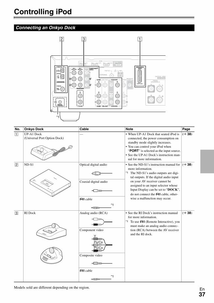
37En
Controlling iPod
Models sold are different depending on the region.
Connecting an Onkyo Dock
CB A
*1
No. Onkyo Dock Cable Note Page
A UP-A1 Dock(Universal Port Option Dock)
— • When UP-A1 Dock that seated iPod is connected, the power consumption on standby mode slightly increases.
• You can control your iPod when “PORT” is selected as the input source.
• See the UP-A1 Dock’s instruction man-ual for more information.
( 38)
B ND-S1 Optical digital audio • See the ND-S1’s instruction manual for more information.
*1 The ND-S1’s audio outputs are digi-tal outputs. If the digital audio input on your AV receiver cannot be assigned to an input selector whose Input Display can be set to “DOCK”, do not connect the u cable, other-wise a malfunction may occur.
( 38)
Coaxial digital audio
u cable
C RI Dock Analog audio (RCA) • See the RI Dock’s instruction manual for more information.
*1 To use u (Remote Interactive), you must make an analog audio connec-tion (RCA) between the AV receiver and the RI dock.
( 38)
Component video
Composite video
u cable
*1
Y
PB/CB
PR/CR
*1

38En
UP-A1 Dock
With the UP-A1 Dock, you can easily play the music, photo, or movie stored on your Apple iPod through the AV receiver and enjoy great sound.You can use the AV receiver’s remote controller to operate your iPod.
Basic Operation
Auto Power OnIf you start iPod playback while the AV receiver is on Standby, the AV receiver will automatically turn on and select your iPod as the input source.Direct ChangeIf you start iPod playback while listening to another input source, the AV receiver will automatically select your iPod as the input source.Using the AV receiver’s Remote ControllerYou can use the AV receiver’s remote controller to control basic iPod functions ( 39).
Using Your iPod models Alarm ClockYou can use your iPod models Alarm Clock function to automatically turn on your iPod and the AV receiver at a specified time. The AV receiver’s input source will auto-matically be set to the PORT selector.
Note
• To use this function, your iPod must be in the UP-A1 Dock, and the UP-A1 Dock must be connected to the AV receiver.
• This function only works when the Standard mode is set to On.• When you use this function, be sure to set the AV receiver’s vol-
ume control to a suitable level.• You cannot use this function for sound effects on your iPod.
Charging Your iPod models BatteryThe UP-A1 Dock charges your iPod models battery while your iPod is in the UP-A1 Dock and connected to the UNIVERSAL PORT jack on the AV receiver. While your iPod is seated in the UP-A1 Dock, its battery will be charged when the AV receiver is set to “On” or “Standby”.
Note
• When UP-A1 Dock that seated iPod is connected, the power consumption on standby mode slightly increases.
Status Messages• PORT Reading
The AV receiver is checking the connection with the dock.
• PORT Not SupportThe AV receiver do not support the connected dock.
• PORT UP-A1UP-A1 Dock is connected.
Note
• The AV receiver displays the message “UP-A1” for several sec-onds after recognizing the UP-A1.
• When the status message is not displayed on the AV receiver’s display, check the connection to your iPod.
ND-S1
With the ND-S1 Digital Media Transport, you can easily play the music stored on your iPod through the AV receiver and enjoy great sound.The ND-S1 processes the digital audio signal directly from your iPod for high-quality digital audio output (opti-cal or coaxial).
Note
• Set the ND-S1 iPod/PC Mode to “iPod”.• Set the AV receiver’s Input Display to “DOCK” ( 20).
RI Dock
With the RI Dock, you can easily play the music stored on your Apple iPod through the AV receiver and enjoy great sound, and watch iPod slideshows and videos on your TV. In addition, the onscreen display (OSD) allows you to view, navigate, and select your iPod’s contents on your TV, and with the supplied remote controller, you can con-trol your iPod from the comfort of your sofa. You can even use the AV receiver’s remote controller to operate your iPod.
Using the Onkyo Dock
Dock is sold separately.For the latest information on the Onkyo Dock compo-nents, see the Onkyo web site at: http://www.onkyo.comBefore using the Onkyo Dock components, update your iPod with the latest software, available from the Apple web site.For supported iPod models, see the instruction man-ual of the Onkyo Dock.
The AV receiver may take several seconds to startup, so you might not hear the first few seconds of the first song.
Operating Notes• Functionality depends on your iPod model and generation.• Before selecting a different input source, stop iPod playback
to prevent the AV receiver from selecting the iPod input source by mistake.
• If any accessories are connected to your iPod, the AV receiver may not be able to select the input source properly.
• When connecting UP-A1 Dock to the radio tuner UP-DT1 with AUTO selected by the tuner’s Mode Selector switch, you can switch the input source between UP-A1 Dock and the tuner, by pressing PORT repeatedly on the front panel.
• While your iPod is in the UP-A1 Dock, its volume control has no effect. If you adjust your iPod models volume control while it’s in the UP-A1 Dock, make sure it’s not set too high before you reconnect your headphones.
• The Auto Power On function will not work if you set your iPod in the UP-A1 Dock while it is playing.
• Do not turn off the power with the iPod still connected to this unit via the UP-A1 Dock.
• Set your iPod in the UP-A1 Dock after the AV receiver turns on.
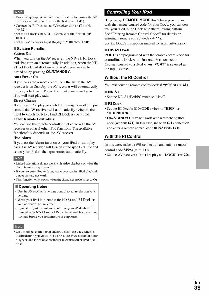
39En
Note
• Enter the appropriate remote control code before using the AV receiver’s remote controller for the first time ( 41).
• Connect the RI Dock to the AV receiver with an u cable ( 37).
• Set the RI Dock’s RI MODE switch to “HDD” or “HDD/DOCK”.
• Set the AV receiver’s Input Display to “DOCK” ( 20).
System FunctionSystem OnWhen you turn on the AV receiver, the ND-S1, RI Dock and iPod turn on automatically. In addition, when the ND-S1, RI Dock and iPod are on, the AV receiver can be turned on by pressing ON/STANDBY.Auto Power On
If you press the remote controller’s 1 while the AV receiver is on Standby, the AV receiver will automatically turn on, select your iPod as the input source, and your iPod will start playback.Direct ChangeIf you start iPod playback while listening to another input source, the AV receiver will automatically switch to the input to which the ND-S1and RI Dock is connected.Other Remote ControllersYou can use the remote controller that came with the AV receiver to control other iPod functions. The available functionality depends on the AV receiver.iPod AlarmIf you use the Alarm function on your iPod to start play-back, the AV receiver will turn on at the specified time and select your iPod as the input source automatically.
Note
• Linked operations do not work with video playback or when the alarm is set to play a sound.
• If you use your iPod with any other accessories, iPod playback detection may not work.
• This function only works when the Standard mode is set to On.
Note
• On the 5th generation iPod and iPod nano, the click wheel is disabled during playback. For ND-S1, use iPod to start and stop playback and the remote controller to control other iPod func-tions.
By pressing REMOTE MODE that’s been programmed with the remote control code for your Dock, you can con-trol your iPod in the Dock with the following buttons.See “Entering Remote Control Codes” for details on entering a remote control code ( 41).See the Dock’s instruction manual for more information.
UP-A1 DockPORT is preprogrammed with the remote control code for controlling a Dock with Universal Port connector.You can control your iPod when “PORT” is selected as the input source.
Without the RI Control
You must enter a remote control code 82990 first ( 41).
ND-S1• Set the ND-S1 iPod/PC mode to “iPod”.
RI Dock• Set the RI Dock’s RI MODE switch to “HDD” or
“HDD/DOCK”.• ON/STANDBY may not work with a remote control
code (without u). In this case, make an u connection and enter a remote control code 81993 (with u).
With the RI Control
In this case, make an u connection and enter a remote
control code 81993 (with u).• Set the AV receiver’s Input Display to “DOCK” ( 20).
Operating Notes• Use the AV receiver’s volume control to adjust the playback
volume.• While your iPod is inserted in the ND-S1 and RI Dock, its
volume control has no effect.• If you do adjust the volume control on your iPod while it’s
inserted in the ND-S1and RI Dock, be careful that it’s not set too loud before you reconnect your earphones.
Controlling Your iPod
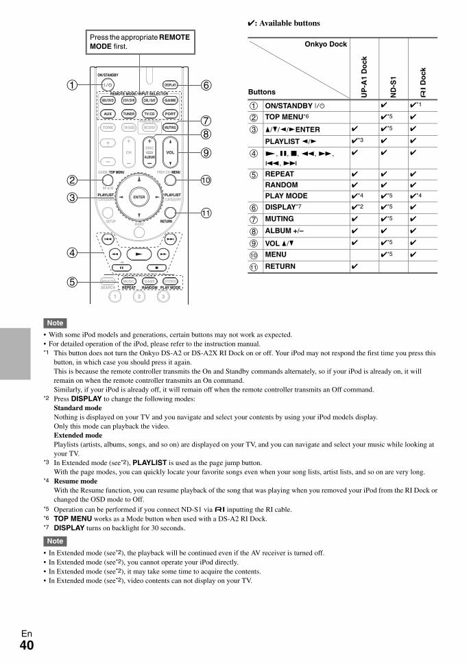
40En
: Available buttons
Note
• With some iPod models and generations, certain buttons may not work as expected.• For detailed operation of the iPod, please refer to the instruction manual.*1 This button does not turn the Onkyo DS-A2 or DS-A2X RI Dock on or off. Your iPod may not respond the first time you press this
button, in which case you should press it again.This is because the remote controller transmits the On and Standby commands alternately, so if your iPod is already on, it will remain on when the remote controller transmits an On command.Similarly, if your iPod is already off, it will remain off when the remote controller transmits an Off command.
*2 Press DISPLAY to change the following modes:Standard modeNothing is displayed on your TV and you navigate and select your contents by using your iPod models display.Only this mode can playback the video.Extended modePlaylists (artists, albums, songs, and so on) are displayed on your TV, and you can navigate and select your music while looking at your TV.
*3 In Extended mode (see*2), PLAYLIST is used as the page jump button.With the page modes, you can quickly locate your favorite songs even when your song lists, artist lists, and so on are very long.
*4 Resume modeWith the Resume function, you can resume playback of the song that was playing when you removed your iPod from the RI Dock or changed the OSD mode to Off.
*5 Operation can be performed if you connect ND-S1 via u inputting the RI cable.*6 TOP MENU works as a Mode button when used with a DS-A2 RI Dock.*7 DISPLAY turns on backlight for 30 seconds.
Note
• In Extended mode (see*2), the playback will be continued even if the AV receiver is turned off.• In Extended mode (see*2), you cannot operate your iPod directly.• In Extended mode (see*2), it may take some time to acquire the contents.• In Extended mode (see*2), video contents can not display on your TV.
b
c
a
g
d
e
h
j
i
k
f
Press the appropriate REMOTE MODE first.
UP
-A1
Do
ck
ND
-S1
u D
ock
a ON/STANDBY 9 *1
b TOP MENU*6 *5
c q/w/e/rENTER *5
PLAYLIST e/r *3
d 1, 3, 2, 5, 4, 7, 6
e REPEAT
RANDOM
PLAY MODE *4 *5 *4
f DISPLAY*7 *2 *5
g MUTING *5
h ALBUM +/–
i VOL q/w *5
j MENU *5
k RETURN
Onkyo Dock
Buttons
41En
Controlling Other ComponentsYou can use the AV receiver’s remote controller (RC-762M) to control your other AV components. This section explains how to enter the remote control code (with the default underlined) for a component that you want to control: DVD, TV, CD, etc.
The following REMOTE MODE are preprogrammed with remote control codes for controlling the components listed. You do not need to enter a remote control code to control these components.For details on controlling these components, see the pages indicated.
You’ll need to enter a code for each component that you want to control.
Onkyo components that are connected via u are con-trolled by pointing the remote controller at the AV receiver, not the component. This allows you to control components that are out of view, in a rack, for example.
If you want to control an Onkyo component by pointing the remote controller directly at it, or you want to control an Onkyo component that’s not connected via u, use the following remote control codes:• BD/DVD
30627: Onkyo DVD player without u
• TV/CD71817:
Onkyo CD player without u11807:
Onkyo TV
Preprogrammed Remote Control Codes
BD/DVD Onkyo Blu-ray Disc player ( 42)TV/CD Onkyo CD player ( 42)PORT Onkyo Universal Port Option ( 39)
Entering Remote Control Codes
1 Look up the appropriate remote control code in the Remote Control Codes for Onkyo Compo-nents Connected via u.
2 While holding down REMOTE MODE to which you want to enter a code, press and hold down DISPLAY (about 3 seconds).
Note
• Remote control codes cannot be entered for RECEIVER.• Apart from RECEIVER, remote control codes from any
category can be entered for REMOTE MODE. However, these buttons also work as input selector buttons ( 19), so choose a REMOTE MODE that corresponds with the input to which you connect your component. For example, if you connect your CD player to the CD input, choose TV/CD when entering its remote control code.
3 Within 30 seconds, use the number buttons to enter the 5-digit remote control code.The remote indicator flashes twice.If the remote control code is not entered success-fully, the remote indicator will flash once slowly.
Remote Control Codes for Onkyo Components Connected via u
1 Make sure the Onkyo component is connected with an u cable and an analog audio cable (RCA).
See “Connecting Onkyo u Components” for details ( 16).
2 Enter the appropriate remote control code for REMOTE MODE.• BD/DVD
31612: Onkyo DVD player with u
• TV/CD71327:
Onkyo CD player with u42157:
Onkyo cassette tape deck player with u• PORT
81993: Onkyo Dock
See the previous section for how to enter remote control codes.
Note
• When using a cassette tape deck connected via u, press and hold TV/CD to switch to TAPE.
3 Press REMOTE MODE, point the remote control-ler at the AV receiver, and operate the component.
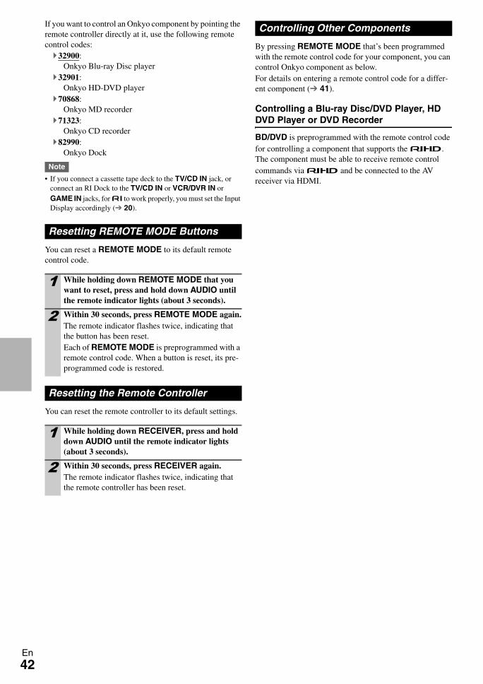
42En
If you want to control an Onkyo component by pointing the remote controller directly at it, use the following remote control codes:
32900: Onkyo Blu-ray Disc player
32901: Onkyo HD-DVD player
70868: Onkyo MD recorder
71323: Onkyo CD recorder
82990: Onkyo Dock
Note
• If you connect a cassette tape deck to the TV/CD IN jack, or connect an RI Dock to the TV/CD IN or VCR/DVR IN or GAME IN jacks, for u to work properly, you must set the Input Display accordingly ( 20).
You can reset a REMOTE MODE to its default remote control code.
You can reset the remote controller to its default settings.
By pressing REMOTE MODE that’s been programmed with the remote control code for your component, you can control Onkyo component as below.For details on entering a remote control code for a differ-ent component ( 41).
Controlling a Blu-ray Disc/DVD Player, HD DVD Player or DVD Recorder
BD/DVD is preprogrammed with the remote control code for controlling a component that supports the p. The component must be able to receive remote control commands via p and be connected to the AV receiver via HDMI.
Resetting REMOTE MODE Buttons
1 While holding down REMOTE MODE that you want to reset, press and hold down AUDIO until the remote indicator lights (about 3 seconds).
2 Within 30 seconds, press REMOTE MODE again.The remote indicator flashes twice, indicating that the button has been reset.Each of REMOTE MODE is preprogrammed with a remote control code. When a button is reset, its pre-programmed code is restored.
Resetting the Remote Controller
1 While holding down RECEIVER, press and hold down AUDIO until the remote indicator lights (about 3 seconds).
2 Within 30 seconds, press RECEIVER again.The remote indicator flashes twice, indicating that the remote controller has been reset.
Controlling Other Components
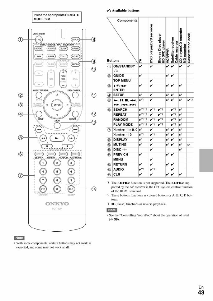
43En
Note
• With some components, certain buttons may not work as expected, and some may not work at all.
: Available buttons
*1 The p function is not supported. The p sup-ported by the AV receiver is the CEC system control function of the HDMI standard.
*2 These buttons functions as colored buttons or A, B, C, D but-tons.
*3 3 (Pause) functions as reverse playback.
Note
• See the “Controlling Your iPod” about the operation of iPod ( 39).
b
c
a h
d
e
g
f
i
j
n
l
k
m
Press the appropriate REMOTE MODE first.
TV
DV
D p
laye
r/D
VD
rec
ord
er
Blu
-ray
Dis
c p
laye
rH
D D
VD
pla
yer
VC
R/P
VR
Sat
ellit
e re
ceiv
erC
able
rec
eive
rC
D p
laye
r/C
D r
eco
rder
MD
rec
ord
erC
asse
tte
tap
e d
eck
a ON/STANDBY 9
b GUIDE
TOP MENU
c q/w/e/rENTER
d SETUP
e 1, 3, 2, 5, 4, 7, 6
*1 *3
f SEARCH *1*2 *1 *2 *2
REPEAT *1*2 *2 *2
RANDOM *1*2 *1 *2 *2
PLAY MODE *1*2 *1 *2 *2
g Number: 1 to 9, 0
Number: +10 *1 *1
h DISPLAY
i MUTING
j DISC +/–
k PREV CH
MENU
l RETURN
m AUDIO *1 *1
n CLR
Components
Buttons
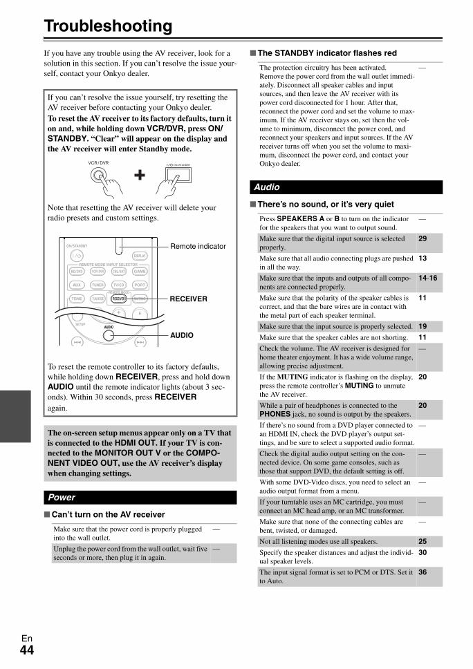
44En
TroubleshootingIf you have any trouble using the AV receiver, look for a solution in this section. If you can’t resolve the issue your-self, contact your Onkyo dealer.
Can’t turn on the AV receiver
The STANDBY indicator flashes red
There’s no sound, or it’s very quiet
If you can’t resolve the issue yourself, try resetting the AV receiver before contacting your Onkyo dealer.To reset the AV receiver to its factory defaults, turn it on and, while holding down VCR/DVR, press ON/STANDBY. “Clear” will appear on the display and the AV receiver will enter Standby mode.
Note that resetting the AV receiver will delete your radio presets and custom settings.
To reset the remote controller to its factory defaults, while holding down RECEIVER, press and hold down AUDIO until the remote indicator lights (about 3 sec-onds). Within 30 seconds, press RECEIVERagain.
The on-screen setup menus appear only on a TV that is connected to the HDMI OUT. If your TV is con-nected to the MONITOR OUT V or the COMPO-NENT VIDEO OUT, use the AV receiver’s display when changing settings.
Power
Make sure that the power cord is properly plugged into the wall outlet.
—
Unplug the power cord from the wall outlet, wait five seconds or more, then plug it in again.
—
AUDIO
RECEIVER
Remote indicator
The protection circuitry has been activated.Remove the power cord from the wall outlet immedi-ately. Disconnect all speaker cables and input sources, and then leave the AV receiver with its power cord disconnected for 1 hour. After that, reconnect the power cord and set the volume to max-imum. If the AV receiver stays on, set then the vol-ume to minimum, disconnect the power cord, and reconnect your speakers and input sources. If the AV receiver turns off when you set the volume to maxi-mum, disconnect the power cord, and contact your Onkyo dealer.
—
Audio
Press SPEAKERS A or B to turn on the indicator for the speakers that you want to output sound.
—
Make sure that the digital input source is selected properly.
29
Make sure that all audio connecting plugs are pushed in all the way.
13
Make sure that the inputs and outputs of all compo-nents are connected properly.
14-16
Make sure that the polarity of the speaker cables is correct, and that the bare wires are in contact with the metal part of each speaker terminal.
11
Make sure that the input source is properly selected. 19
Make sure that the speaker cables are not shorting. 11
Check the volume. The AV receiver is designed for home theater enjoyment. It has a wide volume range, allowing precise adjustment.
—
If the MUTING indicator is flashing on the display, press the remote controller’s MUTING to unmute the AV receiver.
20
While a pair of headphones is connected to the PHONES jack, no sound is output by the speakers.
20
If there’s no sound from a DVD player connected to an HDMI IN, check the DVD player’s output set-tings, and be sure to select a supported audio format.
—
Check the digital audio output setting on the con-nected device. On some game consoles, such as those that support DVD, the default setting is off.
—
With some DVD-Video discs, you need to select an audio output format from a menu.
—
If your turntable uses an MC cartridge, you must connect an MC head amp, or an MC transformer.
—
Make sure that none of the connecting cables are bent, twisted, or damaged.
—
Not all listening modes use all speakers. 25
Specify the speaker distances and adjust the individ-ual speaker levels.
30
The input signal format is set to PCM or DTS. Set it to Auto.
36
45En
Only the front speakers produce sound
Only the center speaker produces sound
The surround speakers produce no sound
The center speaker produces no sound
The subwoofer produces no sound
There’s no sound with a certain signal format
Can’t get 5.1 playback
The volume cannot be set to 79
Noise can be heard
The Late Night function doesn’t work
About DTS signals
The beginning of audio received by an HDMI IN can’t be heard
There’s no picture
When the Stereo or Mono listening mode is selected, only the front speakers and subwoofer produce sound.
—
Check the Speaker Configuration. 30
If you use the Dolby Pro Logic II Movie, Dolby Pro Logic II Music, or Dolby Pro Logic II Game listen-ing mode with a mono source, such as an AM radio station or mono TV program, the sound is concen-trated in the center speaker.
—
Make sure the speakers are configured correctly. 30
When the T-D (Theater-Dimensional), Stereo or Mono listening mode is selected, the surround speakers produce no sound.
—
Depending on the source and current listening mode, not much sound may be produced by the surround speakers. Try selecting another listening mode.
—
Make sure the speakers are configured correctly. 30
When the Stereo or Mono listening mode is selected, the center speaker produces no sound.
—
Make sure the speakers are configured correctly. 30
The subwoofer outputs no sound while only Speak-ers B is on. Turn on Speakers A.
10
When you play source material that contains no information in the LFE channel, the subwoofer pro-duces no sound.
—
Make sure the speakers are configured correctly. 30
Check the digital audio output setting on the con-nected device. On some game consoles, such as those that support DVD, the default setting is off.
—
With some DVD-Video discs, you need to select an audio output format from a menu.
—
Depending on the input signal, some listening modes cannot be selected.
25–27
When speaker B is turned on, Speakers A is reduced to 2.1 channel playback.
10
You can not always select all of the listening modes, depending on the number of the speakers connected.
25–27
After the volume level of each individual speaker has been adjusted, the maximum volume may be reduced.
31
Using cable ties to bundle audio cables with power cords, speaker cables, and so on may degrade the audio performance, so don’t do it.
—
An audio cable may be picking up interference. Try repositioning your cables.
—
Make sure the source material is Dolby Digital, Dolby Digital Plus, and Dolby TrueHD.
34
When DTS program material ends and the DTS bit-stream stops, the AV receiver remains in DTS listen-ing mode and the DTS indicator remains on. This is to prevent noise when you use the pause, fast for-ward, or fast reverse function on your player. If you switch your player from DTS to PCM, because the AV receiver does not switch formats immediately, you may not hear any sound, in which case you should stop your player for about three seconds, and then resume playback.
—
With some CD and LD players, you won’t be able to playback DTS material properly even though your player is connected to a digital input on the AV receiver. This is usually because the DTS bitstream has been processed (e.g., output level, sampling rate, or frequency response changed) and the AV receiver doesn’t recognize it as a genuine DTS signal. In such cases, you may hear noise.
—
When playing DTS program material, using the pause, fast forward, or fast reverse function on your player may produce a short audible noise. This is not a malfunction.
—
Since it takes longer to identify the format of an HDMI signal than it does for other digital audio sig-nals, audio output may not start immediately.
—
Video
Make sure that all video connecting plugs are pushed in all the way.
13
Make sure that each video component is properly connected.
14, 15
If the video source is connected to a component video input, you must assign that input to an input selector, and your TV must be connected to COM-PONENT VIDEO MONITOR OUT.
15, 29
If the video source is connected to a composite video input, your TV must be connected to the correspond-ing composite video output.
15
If the video source is connected to an HDMI input, you must assign that input to an input selector, and your TV must be connected to the HDMI OUT.
14, 29
On your TV, make sure that the video input to which the AV receiver is connected is selected.
—
46En
There’s no picture from a source connected to an HDMI IN
The on-screen menus don’t appear
Reception is noisy, FM stereo reception is noisy, or the FM STEREO indicator doesn’t light
The remote controller doesn’t work
Can’t control other components
There’s no sound
There’s no video
The AV receiver’s remote controller doesn’t control your iPod
Reliable operation with an HDMI-to-DVI adapter is not guaranteed. In addition, video signals from a PC are not guaranteed.
49
On your TV, make sure that the video input to which the AV receiver is connected is selected.
—
When the AV receiver doesn’t connect TV with HDMI, onscreen menus are not displayed.
—
Tuner
Relocate your antenna. —
Move the AV receiver away from your TV or com-puter.
—
Listen to the station in mono. 21
When listening to an AM station, operating the remote controller may cause noise.
—
Passing cars and airplanes can cause interference. —
Concrete walls weaken radio signals. —
If nothing improves the reception, install an outdoor antenna.
—
Remote Controller
Before operating this unit, be sure to press RECEIVER.
—
Make sure that the batteries are installed with the correct polarity.
4
Install new batteries. Don’t mix different types of batteries, or old and new batteries.
4
Make sure that the remote controller is not too far away from the AV receiver, and that there’s no obstruction between the remote controller and the AV receiver’s remote control sensor.
4
Make sure that the AV receiver is not subjected to direct sunshine or inverter-type fluorescent lights. Relocate if necessary.
—
If the AV receiver is installed in a rack or cabinet with colored-glass doors, the remote controller may not work reliably when the doors are closed.
—
Make sure you’ve selected the correct remote con-troller mode.
9, 42
Make sure you’ve entered the correct remote control code.
41
Make sure to set the same ID on both the AV receiver and remote controller.
32
If it’s an Onkyo component, make sure that the u cable and analog audio cable are connected properly. Connecting only an u cable won’t work.
16
Make sure you’ve selected the correct remote con-troller mode.
9, 42
If you’ve connected an cassette tape deck, to the TV/CD IN jack, or an RI Dock to the TV/CD IN or GAME IN or VCR/DVR IN jacks, for the remote controller to work properly, you must set the display.
20
If you cannot operate it, you will need to enter the appropriate remote control code.
41
To control an Onkyo component that’s connected via u, point the remote controller at the AV receiver. Be sure to enter the appropriate remote control code first.
41
To control an Onkyo component that’s not connected via u, point the remote controller at the compo-nent. Be sure to enter the appropriate remote control code first.
41
UP-A1 Dock for iPod
Make sure your iPod is actually playing. —
Make sure your iPod is inserted properly in the Dock.
—
Make sure the UP-A1 Dock is connected to the UNI-VERSAL PORT jack on the AV receiver.
—
Make sure the AV receiver is turned on, the correct input source is selected, and the volume is turned up.
—
Make sure the plugs are pushed in all the way. —
Try resetting your iPod. —
Make sure that your iPod’s TV OUT setting is set to On.
—
Make sure the correct input is selected on your TV or the AV receiver.
—
Some versions of the iPod do not output video. —
Make sure your iPod is properly inserted in the Dock. If your iPod is in a case, it may not connect properly to the Dock. Always remove your iPod from the case before inserting it into the Dock.
—
The iPod cannot be operated while it’s displaying the Apple logo.
—
Make sure you’ve selected the right remote mode. —
When you use the AV receiver’s remote controller, point it toward your AV receiver.
—
When connecting UP-A1 Dock to the radio tuner UP-DT1 with AUTO selected by the tuner’s Mode Selector switch, you can switch the input source between UP-A1 Dock and the tuner, by pressing PORT repeatedly on the front panel.
—
If you still can’t control your iPod, start playback by pressing your iPod’s Play button. Remote operation should then be possible.
—
Try resetting your iPod. —
Depending on your iPod, some buttons may not work as expected.
—
47En
The AV receiver unexpectedly selects your iPod as the input source
Can’t record
The sound changes when I connect my headphones
How do I change the language of a multiplex source
The u functions don’t work
The following settings can be made for the composite video inputsYou must use the buttons on the unit to make these set-tings.
1. While holding down the input selector button for the input source that you want to set, press SETUP.
2. Use e/r to change the setting.3. Press the input selector button for the input source that you
want to set when you’ve finished.
• Video AttenuationThis setting can be made for the BD/DVD, VCR/DVR, CBL/SAT, GAME, or AUX input.If you have a games console connected to the composite video input, and the picture isn’t very clear, you can attenuate the gain.Video ATT:OFF: (default).Video ATT:ON: Gain is reduced by 2 dB.
Always pause iPod playback before selecting a dif-ferent input source. If playback is not paused, the Direct Change function may select your iPod as the input source by mistake during the transition between tracks.
—
Recording
On your recorder, make sure the correct input is selected.
—
To prevent signal loops and damage to the AV receiver, input signals are not fed through to outputs with the same name (e.g., VCR/DVR IN to VCR/DVR OUT).
—
Others
When a pair of headphones is connected, the listen-ing mode is set to Stereo, unless it’s already set to Stereo, Mono, or Direct.
—
Use the “Multiplex” setting on the “Audio Adjust” menu to select “Main” or “Sub”.
31
To use u, you must make an u connection and an analog audio connection (RCA) between the compo-nent and AV receiver, even if they are connected dig-itally.
16
The AV receiver contains a microcomputer for signal processing and control functions. In very rare situations, severe interference, noise from an external source, or static electricity may cause it to lockup. In the unlikely event that this happens, unplug the power cord from the wall outlet, wait at least five seconds, and then plug it back in again.
Onkyo is not responsible for damages (such as CD rental fees) due to unsuccessful recordings caused by the unit’s malfunction. Before you record important data, make sure that the material will be recorded cor-rectly.
Before disconnecting the power cord from the wall out-let, set the AV receiver to Standby.
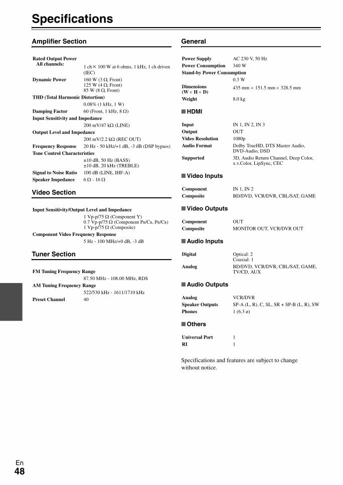
48En
Specifications
Amplifier Section
Video Section
Tuner Section
General
HDMI
Video Inputs
Video Outputs
Audio Inputs
Audio Outputs
Others
Specifications and features are subject to change without notice.
Rated Output Power All channels: 1 ch × 100 W at 6 ohms, 1 kHz, 1 ch driven
(IEC)
Dynamic Power 160 W (3 Ω, Front)125 W (4 Ω, Front)85 W (8 Ω, Front)
THD (Total Harmonic Distortion)0.08% (1 kHz, 1 W)
Damping Factor 60 (Front, 1 kHz, 8 Ω)
Input Sensitivity and Impedance200 mV/47 kΩ (LINE)
Output Level and Impedance200 mV/2.2 kΩ (REC OUT)
Frequency Response 20 Hz - 50 kHz/+1 dB, -3 dB (DSP bypass)
Tone Control Characteristies±10 dB, 50 Hz (BASS)±10 dB, 20 kHz (TREBLE)
Signal to Noise Ratio 100 dB (LINE, IHF-A)
Speaker Impedance 6 Ω - 16 Ω
Input Sensitivity/Output Level and Impedance1 Vp-p/75 Ω (Component Y)0.7 Vp-p/75 Ω (Component PB/CB, PR/CR)1 Vp-p/75 Ω (Composite)
Component Video Frequency Response5 Hz - 100 MHz/+0 dB, -3 dB
FM Tuning Frequency Range87.50 MHz - 108.00 MHz, RDS
AM Tuning Frequency Range522/530 kHz - 1611/1710 kHz
Preset Channel 40
Power Supply AC 230 V, 50 Hz
Power Consumption 340 W
Stand-by Power Consumption0.3 W
Dimensions (W × H × D)
435 mm × 151.5 mm × 328.5 mm
Weight 8.0 kg
Input IN 1, IN 2, IN 3
Output OUT
Video Resolution 1080p
Audio Format Dolby TrueHD, DTS Master Audio, DVD-Audio, DSD
Supported 3D, Audio Return Channel, Deep Color, x.v.Color, LipSync, CEC
Component IN 1, IN 2
Composite BD/DVD, VCR/DVR, CBL/SAT, GAME
Component OUT
Composite MONITOR OUT, VCR/DVR OUT
Digital Optical: 2Coaxial: 1
Analog BD/DVD, VCR/DVR, CBL/SAT, GAME, TV/CD, AUX
Analog VCR/DVR
Speaker Outputs SP-A (L, R), C, SL, SR + SP-B (L, R), SW
Phones 1 (6.3 ø)
Universal Port 1
RI 1
49En
About HDMIDesigned to meet the increased demands of digital TV, HDMI (High Definition Multimedia Interface) is a new digital interface standard for connecting TVs, projectors, Blu-ray Disc/DVD players, set-top boxes, and other video compo-nents. Until now, several separate video and audio cables have been required to connect AV components. With HDMI, a single cable can carry control signals, digital video, and up to eight channels of digital audio (2-channel PCM, multichan-nel digital audio, and multichannel PCM).The HDMI video stream (i.e., video signal) is compatible with DVI (Digital Visual Interface)*1, so TVs and displays with a DVI input can be connected by using an HDMI-to-DVI adapter cable. (This may not work with some TVs and displays, resulting in no picture.)The AV receiver uses HDCP (High-bandwidth Digital Content Protection)*2, so only HDCP-compatible components can display the picture.
Supported Audio Formats
• 2-channel linear PCM (32–192 kHz, 16/20/24 bit)• Multichannel linear PCM (up to 7.1 ch, 32–192 kHz, 16/20/24 bit)• Bitstream (DSD, Dolby Digital, Dolby Digital Plus, Dolby TrueHD, DTS, DTS-HD High Resolution Audio, DTS-HD
Master Audio)Your Blu-ray Disc/DVD player must also support HDMI output of the above audio formats.
About Copyright Protection
The AV receiver supports HDCP (High-bandwidth Digital Content Protection)*2, a copy-protection system for digital video signals. Other devices connected to the AV receiver via HDMI must also support HDCP.
*1 DVI (Digital Visual Interface): The digital display interface standard set by the DDWG*3 in 1999.*2 HDCP (High-bandwidth Digital Content Protection): The video encryption technology developed by Intel for HDMI/DVI. It’s
designed to protect video content and requires a HDCP-compatible device to display the encrypted video. *3 DDWG (Digital Display Working Group): Lead by Intel, Compaq, Fujitsu, Hewlett Packard, IBM, NEC, and Silicon Image, this
open industry group’s objective is to address the industry’s requirements for a digital connectivity specification for high-performance PCs and digital displays.
Note
• The HDMI video stream is compatible with DVI (Digital Visual Interface), so TVs and displays with a DVI input can be connected by using an HDMI-to-DVI adapter cable. (Note that DVI connections only carry video, so you’ll need to make a separate connection for audio.) However, reliable operation with such an adapter is not guaranteed. In addition, video signals from a PC are not supported.
• The HDMI audio signal (sampling rate, bit length, etc.) may be restricted by the connected source component. If the picture is poor or there’s no sound from a component connected via HDMI, check its setup. Refer to the connected component’s instruction manual for details.
The AV receiver’s HDMI interface is based on the following:Audio Return Channel, 3D, x.v.Color, Deep Color, Lip Sync, DTS-HD Master Audio, DTS-HD High Resolution Audio, Dolby TrueHD, Dolby Digital Plus, DSD and Multichannel PCM
50En
Using an RIHD-compatible TV, Player, or Recorder
p, which stands for Remote Interactive over HDMI, is the name of the system control function found on Onkyo components. The AV receiver can be used with CEC (Consumer Electronics Control), which allows system control over HDMI and is part of the HDMI standard. CEC provides interoperability between various components, however, opera-tion with components other than p-compatible components cannot be guaranteed.
About p-compatible componentsThe following components are p-compatible. (As of February 2010) See the Onkyo web site for latest infor-mation.TV• Panasonic VIERA Link compatible TV• Toshiba REGZA-LINK compatible TV• Sharp TV (See Onkyo web site for latest information on
compatible models.)Players/Recorders
• Onkyo and Integra p-compatible players• Panasonic VIERA Link compatible players and record-
ers (only when used together with Panasonic VIERA Link compatible TV)
• Toshiba REGZA-LINK compatible players and record-ers (only when used together with Toshiba REGZA-LINK compatible TV)
• Sharp players and recorders (only when used together with Sharp TV)
* Models other than those mentioned above may have some interoperability if compatible with CEC which is part of the HDMI Standard, but operation cannot be guaranteed.
Note
• Do not connect the p-compatible component more than the following number to the HDMI input terminal so that the linked operations work properly.–Blu-ray Disc/DVD player is up to three.–Blu-ray Disc recorder/DVD recorder/Digital Video Recorder is up to three.–Cable/Satellite Set-top box is up to four.
• Do not connect the AV receiver to the other AV receiver/AV amplifier via HDMI.
• When the p-compatible component more than the above-mentioned is connected, the linked operations are not guaranteed.
Operations that can be performed with p connection
For p-compatible TVThe following linked operation is possible by connecting the AV receiver to an p-compatible TV.• The AV receiver will enter Standby mode when the
power of the TV is turned to Standby.• You can set on the menu screen of the TV to either out-
put the audio from the speakers connected to the AV receiver, or from the speakers of the TV.
• It is possible to output the video/audio from the antenna or from the input jack of the TV from the speakers con-nected to the AV receiver. (A connection such as optical digital cable or similar is required above the HDMI cable.)
• Input to the AV receiver can be selected with the remote controller of the TV.
• Operations such as volume adjustment or similar for the AV receiver can be performed from the remote controller of the TV.
For p-compatible players/recordersThe following link operation is possible by connecting the AV receiver to an p-compatible player/recorder.• When the playback is started on the player/recorder,
input of the AV receiver will switch to the HDMI input of the player/recorder that is playing back.
• Operation of the player/recorder is possible with the remote controller supplied with the AV receiver.
* Not all functions may operate depending on the model.
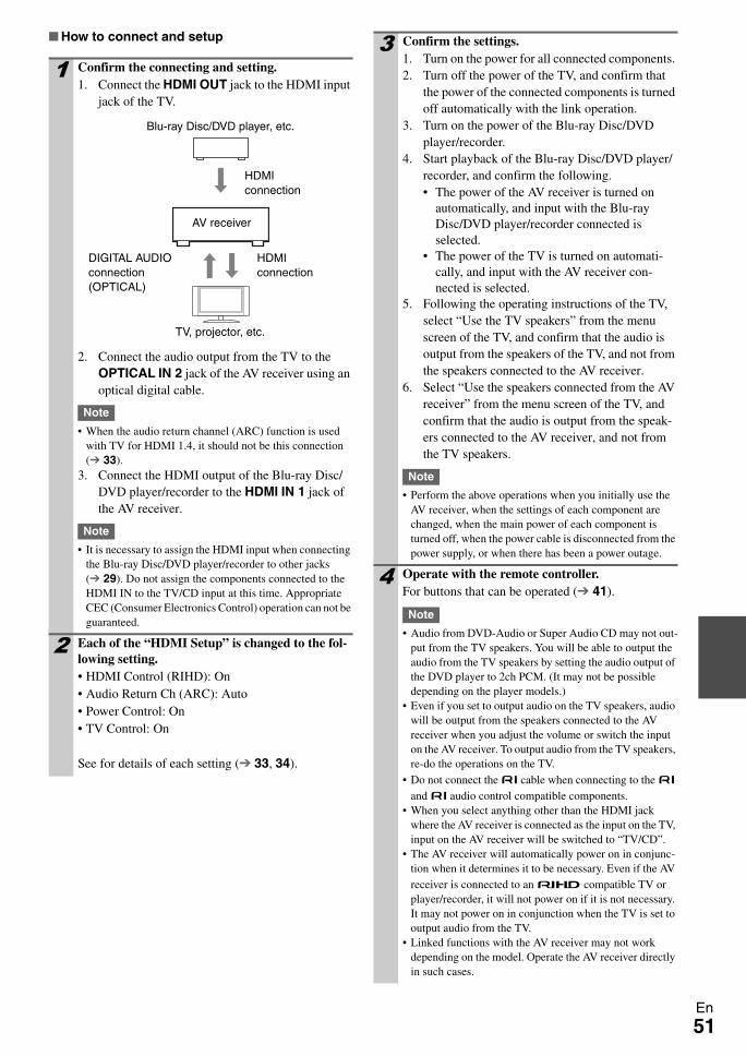
51En
How to connect and setup
1 Confirm the connecting and setting.1. Connect the HDMI OUT jack to the HDMI input
jack of the TV.
2. Connect the audio output from the TV to the OPTICAL IN 2 jack of the AV receiver using an optical digital cable.
Note
• When the audio return channel (ARC) function is used with TV for HDMI 1.4, it should not be this connection ( 33).
3. Connect the HDMI output of the Blu-ray Disc/DVD player/recorder to the HDMI IN 1 jack of the AV receiver.
Note
• It is necessary to assign the HDMI input when connecting the Blu-ray Disc/DVD player/recorder to other jacks ( 29). Do not assign the components connected to the HDMI IN to the TV/CD input at this time. Appropriate CEC (Consumer Electronics Control) operation can not be guaranteed.
2 Each of the “HDMI Setup” is changed to the fol-lowing setting.• HDMI Control (RIHD): On• Audio Return Ch (ARC): Auto• Power Control: On• TV Control: On
See for details of each setting ( 33, 34).
Blu-ray Disc/DVD player, etc.
AV receiver
TV, projector, etc.
DIGITAL AUDIO connection (OPTICAL)
HDMI connection
HDMI connection
3 Confirm the settings. 1. Turn on the power for all connected components. 2. Turn off the power of the TV, and confirm that
the power of the connected components is turned off automatically with the link operation.
3. Turn on the power of the Blu-ray Disc/DVD player/recorder.
4. Start playback of the Blu-ray Disc/DVD player/recorder, and confirm the following.• The power of the AV receiver is turned on
automatically, and input with the Blu-ray Disc/DVD player/recorder connected is selected.
• The power of the TV is turned on automati-cally, and input with the AV receiver con-nected is selected.
5. Following the operating instructions of the TV, select “Use the TV speakers” from the menu screen of the TV, and confirm that the audio is output from the speakers of the TV, and not from the speakers connected to the AV receiver.
6. Select “Use the speakers connected from the AV receiver” from the menu screen of the TV, and confirm that the audio is output from the speak-ers connected to the AV receiver, and not from the TV speakers.
Note
• Perform the above operations when you initially use the AV receiver, when the settings of each component are changed, when the main power of each component is turned off, when the power cable is disconnected from the power supply, or when there has been a power outage.
4 Operate with the remote controller.For buttons that can be operated ( 41).
Note
• Audio from DVD-Audio or Super Audio CD may not out-put from the TV speakers. You will be able to output the audio from the TV speakers by setting the audio output of the DVD player to 2ch PCM. (It may not be possible depending on the player models.)
• Even if you set to output audio on the TV speakers, audio will be output from the speakers connected to the AV receiver when you adjust the volume or switch the input on the AV receiver. To output audio from the TV speakers, re-do the operations on the TV.
• Do not connect the u cable when connecting to the u and u audio control compatible components.
• When you select anything other than the HDMI jack where the AV receiver is connected as the input on the TV, input on the AV receiver will be switched to “TV/CD”.
• The AV receiver will automatically power on in conjunc-tion when it determines it to be necessary. Even if the AV receiver is connected to an p compatible TV or player/recorder, it will not power on if it is not necessary. It may not power on in conjunction when the TV is set to output audio from the TV.
• Linked functions with the AV receiver may not work depending on the model. Operate the AV receiver directly in such cases.

SN 29400408
Y1001-1
(C) Copyright 2010 ONKYO CORPORATION Japan. All rights reserved.* 2 9 4 0 0 4 0 8 *
Sales & Product Planning Div. : 2-1, Nisshin-cho, Neyagawa-shi, OSAKA 572-8540, JAPANTel: 072-831-8023 Fax: 072-831-8163
ONKYO U.S.A. CORPORATION18 Park Way, Upper Saddle River, N.J. 07458, U.S.A.Tel: 800-229-1687, 201-785-2600 Fax: 201-785-2650 http://www.us.onkyo.com/
ONKYO EUROPE ELECTRONICS GmbHLiegnitzerstrasse 6, 82194 Groebenzell, GERMANYTel: +49-8142-4401-0 Fax: +49-8142-4401-555 http://www.eu.onkyo.com/
ONKYO EUROPE ELECTRONICS GmbH (UK BRANCH)The Coach House 81A High Street, Marlow, Buckinghamshire, SL7 1AB, UKTel: +44-(0)1628-473-350 Fax: +44-(0)1628-401-700
ONKYO CHINA LIMITEDUnit 1 & 12, 9/F, Tower 1, Ever Gain Plaza, 88, Container Port Road, Kwai Chung, N.T., Hong Kong. Tel: 852-2429-3118 Fax: 852-2428-9039http://www.ch.onkyo.com/