Embed Size (px)
Citation preview
FRACTURE AND LIFE © Imperial College Presshttp://www.worldscibooks.com/engineering/p593.html
1
Chapter 1
Introduction and Basic Solid Mechanics
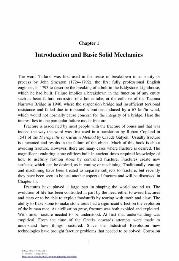
The word ‘failure’ was first used in the sense of breakdown in an entity or
process by John Smeaton (1724–1792), the first fully professional English
engineer, in 1793 to describe the breaking of a bolt in the Eddystone Lighthouse,
which he had built. Failure implies a breakdown in the function of any entity
such as heart failure, corrosion of a boiler tube, or the collapse of the Tacoma
Narrows Bridge in 1940, where the suspension bridge had insufficient torsional
resistance and failed due to torsional vibrations induced by a 67 km/hr wind,
which would not normally cause concern for the integrity of a bridge. Here the
interest lies in one particular failure mode: fracture.
Fracture is associated by most people with the fracture of bones and that was
indeed the way the word was first used in a translation by Robert Copland in
1541 of the Therapeutic or Curative Method by Claudé Galyen.1 Usually fracture
is unwanted and results in the failure of the object. Much of this book is about
avoiding fracture. However, there are many cases where fracture is desired. The
magnificent enduring stone edifices built in ancient times required knowledge of
how to usefully fashion stone by controlled fracture. Fractures create new
surfaces, which can be desired, as in cutting or machining. Traditionally, cutting
and machining have been treated as separate subjects to fracture, but recently
they have been seen to be just another aspect of fracture and will be discussed in
Chapter 11.
Fractures have played a large part in shaping the world around us. The
evolution of life has been controlled in part by the need either to avoid fractures
and tears or to be able to exploit foodstuffs by tearing with tooth and claw. The
ability to flake stone to make stone tools had a significant effect on the evolution
of the human race. As civilisation grew, fracture was both avoided and exploited.
With time, fracture needed to be understood. At first that understanding was
empirical. From the time of the Greeks onwards attempts were made to
understand how things fractured. Since the Industrial Revolution new
technologies have brought fracture problems that needed to be solved. Corrosion
FRACTURE AND LIFE © Imperial College Presshttp://www.worldscibooks.com/engineering/p593.html
Fracture and Life 2
and wear constitute today’s largest failure cost, costing some $120 billion a year
in the US alone, but the cost of fracture is not much less. Hence economically
there is a great need to understand and control fracture. In this chapter the
necessary basics to understand the subsequent chapters are presented.
1.1 What Holds a Solid Together?
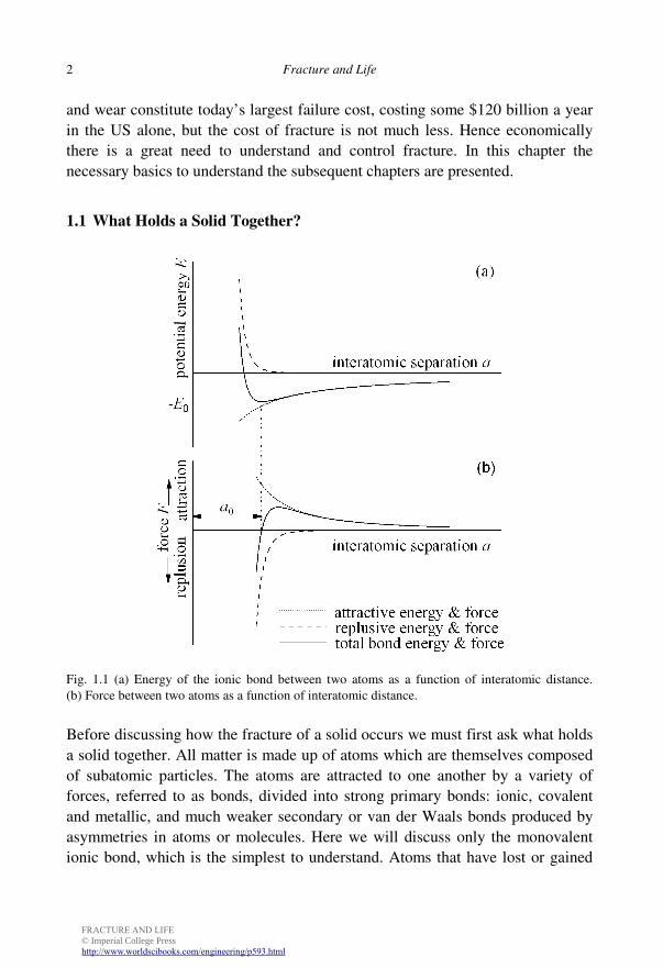
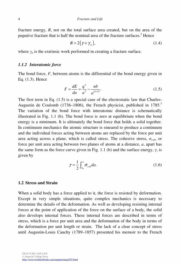
Fig. 1.1 (a) Energy of the ionic bond between two atoms as a function of interatomic distance.
(b) Force between two atoms as a function of interatomic distance.
Before discussing how the fracture of a solid occurs we must first ask what holds
a solid together. All matter is made up of atoms which are themselves composed
of subatomic particles. The atoms are attracted to one another by a variety of
forces, referred to as bonds, divided into strong primary bonds: ionic, covalent
and metallic, and much weaker secondary or van der Waals bonds produced by
asymmetries in atoms or molecules. Here we will discuss only the monovalent
ionic bond, which is the simplest to understand. Atoms that have lost or gained
FRACTURE AND LIFE © Imperial College Presshttp://www.worldscibooks.com/engineering/p593.html
Introduction and Basic Solid Mechanics 3
an electron become positively or negatively charged ions attracting or repulsing
each other. The energy change, Ec, as two unlike monovalent ions are brought
together is given by
2
,c
qE
a= − (1.1)
where a is the interatomic distance, q is the electronic charge. If the ions are in
close proximity to each other they interact and a repulsive energy, Er, is
generated given by
,r n
bE
a= (1.2)
where 6<n<12. The repulsive energy, Er, has a much shorter range than Ec and
the total bond energy between two unlike monovalent ions is thus given by
2
.n
q bE
a a
−= + (1.3)
The bond energy between two atoms in a solid, shown in Fig. 1.1 (a), is similar to
the expression given by Eq. (1.3) regardless of the bond type. The bond energy is
a minimum, −E0, at equilibrium when the interatomic distance is a0.
1.1.1 Surface energy
On a surface an atom has fewer adjacent partners and hence it has a higher
energy of approximately −E0/2. The surface energy, γ, of a solid surface is this
higher energy multiplied by the number of atoms in a unit area. Most materials
have a surface energy in the range of 0.5–10 J/m2. A fracture creates new
surfaces and therefore the minimum or intrinsic energy necessary to create a
fracture of unit area is the surface energy, 2γ. The factor 2 arises because there
are two surfaces. The fracture energy of glass, which behaves as an elastic-brittle
material, is only about four times its surface energy of 1 J/m2. We all know how
brittle glass is and we would live in a very brittle world if the energy necessary to
create a fracture in materials generally was similar to that of glass. Fortunately
the actual fracture energy of most materials is many orders of magnitude greater
than the surface energy because it is usually not possible to produce a fracture
without performing extrinsic work.
Since surface energy does not depend upon how the surface is produced it is
based on the total surface area. When a solid is fractured two surfaces are
produced of nominally the same area. It has become the practice to base the
FRACTURE AND LIFE © Imperial College Presshttp://www.worldscibooks.com/engineering/p593.html
Fracture and Life 4
fracture energy, R, not on the total surface area created, but on the area of the
pupative fracture that is half the nominal area of the fracture surfaces.2 Hence
( )2 ,pR γ γ= + (1.4)
where γp is the extrinsic work performed in creating a fracture surface.
1.1.2 Interatomic force
The bond force, F, between atoms is the differential of the bond energy given in
Eq. (1.3). Hence
( )
2
2 1.
n
dE q nbF
da a a+
= = − (1.5)
The first term in Eq. (1.5) is a special case of the electrostatic law that Charles-
Augustin de Coulomb (1736–1806), the French physicist, published in 1785.3
The variation of the bond force with interatomic distance is schematically
illustrated in Fig. 1.1 (b). The bond force is zero at equilibrium when the bond
energy is a minimum. It is ultimately the bond force that holds a solid together.
In continuum mechanics the atomic structure is smeared to produce a continuum
and the individual forces acting between atoms are replaced by the force per unit
area acting across a plane, which is called stress. The cohesive stress, σcoh, or
force per unit area acting between two planes of atoms at a distance, a, apart has
the same form as the force curve given in Fig. 1.1 (b) and the surface energy, γ, is
given by
0
1.
2coh
adaγ σ
∞
= ∫ (1.6)
1.2 Stress and Strain
When a solid body has a force applied to it, the force is resisted by deformation.
Except in very simple situations, quite complex mechanics is necessary to
determine the details of the deformation. As well as developing resisting internal
forces at the point of application of the force on the surface of a body, the solid
also develops internal forces. These internal forces are described in terms of
stress, which is a force per unit area and the deformation of the body in terms of
the deformation per unit length or strain. The lack of a clear concept of stress
until Augustin-Louis Cauchy (1789–1857) presented his memoir to the French
FRACTURE AND LIFE © Imperial College Presshttp://www.worldscibooks.com/engineering/p593.html
Introduction and Basic Solid Mechanics 5
Academy of Sciences in 1822, created great difficulties for the early mechanics
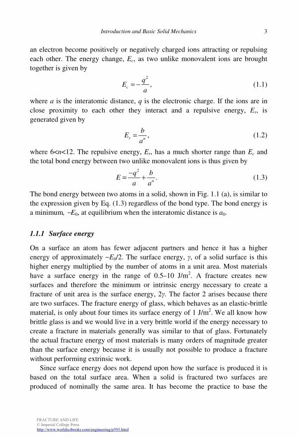
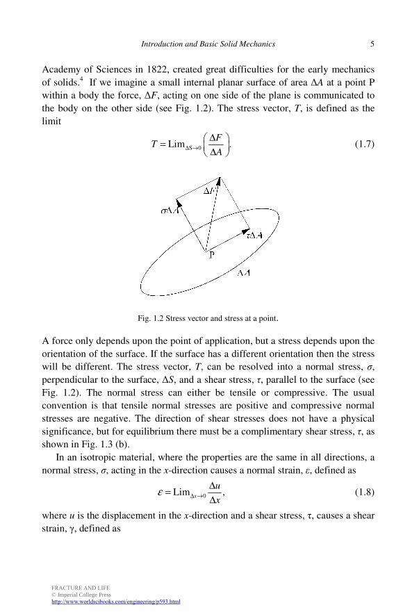
of solids.4 If we imagine a small internal planar surface of area ∆A at a point P
within a body the force, ∆F, acting on one side of the plane is communicated to
the body on the other side (see Fig. 1.2). The stress vector, T, is defined as the
limit
S 0Lim .F
TA
∆ →
∆ =
∆ (1.7)
Fig. 1.2 Stress vector and stress at a point.
A force only depends upon the point of application, but a stress depends upon the
orientation of the surface. If the surface has a different orientation then the stress
will be different. The stress vector, T, can be resolved into a normal stress, σ,
perpendicular to the surface, ∆S, and a shear stress, τ, parallel to the surface (see
Fig. 1.2). The normal stress can either be tensile or compressive. The usual
convention is that tensile normal stresses are positive and compressive normal
stresses are negative. The direction of shear stresses does not have a physical
significance, but for equilibrium there must be a complimentary shear stress, τ, as
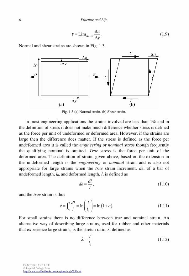
shown in Fig. 1.3 (b).
In an isotropic material, where the properties are the same in all directions, a
normal stress, σ, acting in the x-direction causes a normal strain, ε, defined as
0Lim ,x
u
xε ∆ →
∆=
∆ (1.8)
where u is the displacement in the x-direction and a shear stress, τ, causes a shear
strain, γ, defined as
FRACTURE AND LIFE © Imperial College Presshttp://www.worldscibooks.com/engineering/p593.html
Fracture and Life 6
0Lim .y
u
yγ ∆ →
∆=
∆ (1.9)
Normal and shear strains are shown in Fig. 1.3.
Fig. 1.3 (a) Normal strain. (b) Shear strain.
In most engineering applications the strains involved are less than 1% and in
the definition of stress it does not make much difference whether stress is defined
as the force per unit of undeformed or deformed area. However, if the strains are
large then the difference does matter. If the stress is defined as the force per
undeformed area it is called the engineering or nominal stress though frequently
the qualifying nominal is omitted. True stress is the force per unit of the
deformed area. The definition of strain, given above, based on the extension in
the undeformed length is the engineering or nominal strain and is also not
appropriate for large strains when the true strain increment, de, of a bar of
undeformed length, l0, and deformed length, l, is defined as
,dl
del
= (1.10)
and the true strain is thus
( )0
0
ln ln 1 .l
l
dl le
l lε
= = = + ∫ (1.11)
For small strains there is no difference between true and nominal strain. An
alternative way of describing large strains, used for rubber and other materials
that experience large strains, is the stretch ratio, λ, defined as
0
l
lλ = (1.12)
FRACTURE AND LIFE © Imperial College Presshttp://www.worldscibooks.com/engineering/p593.html
Introduction and Basic Solid Mechanics 7
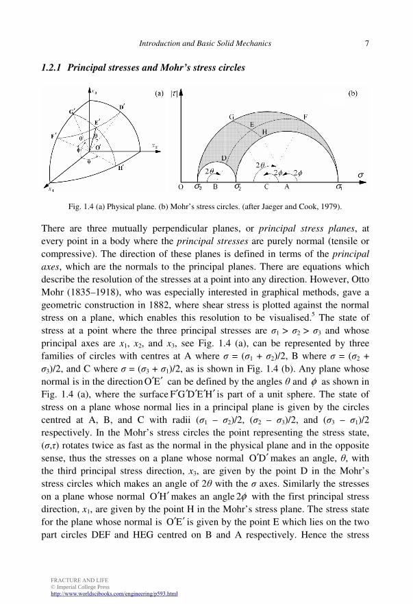
1.2.1 Principal stresses and Mohr’s stress circles
Fig. 1.4 (a) Physical plane. (b) Mohr’s stress circles. (after Jaeger and Cook, 1979).
There are three mutually perpendicular planes, or principal stress planes, at
every point in a body where the principal stresses are purely normal (tensile or
compressive). The direction of these planes is defined in terms of the principal
axes, which are the normals to the principal planes. There are equations which
describe the resolution of the stresses at a point into any direction. However, Otto
Mohr (1835–1918), who was especially interested in graphical methods, gave a
geometric construction in 1882, where shear stress is plotted against the normal
stress on a plane, which enables this resolution to be visualised.5 The state of
stress at a point where the three principal stresses are σ1 > σ2 > σ3 and whose
principal axes are x1, x2, and x3, see Fig. 1.4 (a), can be represented by three
families of circles with centres at A where σ = (σ1 + σ2)/2, B where σ = (σ2 +
σ3)/2, and C where σ = (σ3 + σ1)/2, as is shown in Fig. 1.4 (b). Any plane whose
normal is in the direction O E′ ′ can be defined by the angles θ and φ as shown in
Fig. 1.4 (a), where the surface F G D E H′ ′ ′ ′ ′ is part of a unit sphere. The state of
stress on a plane whose normal lies in a principal plane is given by the circles
centred at A, B, and C with radii (σ1 – σ2)/2, (σ2 – σ3)/2, and (σ3 – σ1)/2
respectively. In the Mohr’s stress circles the point representing the stress state,
(σ,τ) rotates twice as fast as the normal in the physical plane and in the opposite
sense, thus the stresses on a plane whose normal O D′ ′ makes an angle, θ, with
the third principal stress direction, x3, are given by the point D in the Mohr’s
stress circles which makes an angle of 2θ with the σ axes. Similarly the stresses
on a plane whose normal O H′ ′ makes an angle 2φ with the first principal stress
direction, x1, are given by the point H in the Mohr’s stress plane. The stress state
for the plane whose normal is O E′ ′ is given by the point E which lies on the two
part circles DEF and HEG centred on B and A respectively. Hence the stress
FRACTURE AND LIFE © Imperial College Presshttp://www.worldscibooks.com/engineering/p593.html
Fracture and Life 8
state for any plane at a point where the principal stresses are σ1, σ2, and σ3 lies in
the segment that is shaded in Fig. 1.4 (b). More details can be found in the classic
book on rock mechanics by John Jaeger (1907–1979) and Neville Cook (1938–
1998) or other solid mechanics book.6
A stressed body is a strained body. Cauchy showed that strain could be
resolved into components of normal and shear strain, which are mathematically
similar to the components of stress. Hence principal strain planes can be found
where the strain is purely normal and there are Mohr’s strain circles analogous to
his stress circles.
1.3 Elastic Deformation
When the atoms are in equilibrium in a solid that is unstressed, the force between
them is zero and the interatomic distance is a0. The force required to displace the
atom a very small distance is proportional to the displacement and it is this
fundamental behaviour that causes as a spring to increase in length in proportion
to the force. This deformation behaviour is called linear elasticity.
Robert Hooke (1635–1703), a contemporary of Isaac Newton (1642–1727),
discovered linear elastic behaviour in 1660 when he invented a spring
escapement for clocks, but did not publish the result immediately because he
wanted to obtain a patent. When Hooke finally committed himself to print in
1676 he did so in the form of a cryptic anagram. It was not until after the death of
Henry Oldenburg (ca. 1619–1677), the Secretary of the Royal Society whom
Hooke mistrusted and hated,7 that he felt free to publish the solution, ut tensio sic
vis, which translated reads: as the extension so the force.8 Hooke’s law was
concerned with the overall behaviour of a body, but it also applies to internal
stress and strain and the constant of proportionality between stress and strain is a
material constant. This generalisation of Hooke’s law was made by Thomas
Young9 (1773–1829) in a course on popular mechanics at the Royal Institution in
1802 though because the concept of stress had not been introduced his definition
was different to what is used now.10 The constant of elastic proportionality
between normal stress and strain is named Young’s modulus, E, in his honour.
Thus:
.Eσ
ε= (1.13)
FRACTURE AND LIFE © Imperial College Presshttp://www.worldscibooks.com/engineering/p593.html
Introduction and Basic Solid Mechanics 9
The units of Young’s modulus are those of stress. Diamond has the highest
Young’s modulus, 1050 GPa, of any material and the Young’s modulus of other
ceramics is also very high, in the range 200–500 GPa. The Young’s modulus of
metals is generally lower than that of ceramics, but is still high and for most
metals it is in the range 50–210 GPa. Polymers have a much lower Young’s
modulus in the range 1–3 GPa and rubbers both natural and synthetic have a very
low Young’ modulus in the range 2–100 MPa. In this chapter discussion is
limited to isotropic elasticity where the principal axes of stress and strain
coincide.
Shear stress, τ, is also proportional to shear strain, γ, and the constant of
proportionality, µ, is called the shear modulus. Thus:
.τ
µγ
= (1.14)
Cauchy showed in 1829 that only two elastic constants are required to describe
the complete relationship between stress and strain for an isotropic elastic
material.11 However, a third elastic constant, named Poisson’s ratio, ν, after the
French mathematician Siméon Poisson (1781–1840), is frequently used. An
elastic rod that is stretched by a tensile stress contracts laterally in proportion to
the axial strain and the constant of proportionality between the lateral and axial
strain is called the Poisson’s ratio. Thus in the limit in Fig. 1.3 (a),
, 0
vLim .x y
u
y xν ∆ ∆ →
∆ ∆ = −
∆ ∆ (1.15)
Poisson derived the relationship between the shear modulus, Young’s modulus
and Poisson’ ratio which is given by
( )
.2 1
Eµ
ν=
+ (1.16)
Stress distributions are often planar in engineering. Except near any sharp re-
entrant corners, the only appreciable stresses in thin plates, loaded at their edges,
are those in the plane of the plate; such states of stress are called plane stress. The
other archetypal two-dimensional stress state is plane strain where the strain
perpendicular to the plane is zero and the normal stress, σz, perpendicular to the
plane is given in terms of the normal stresses within the plane, σx and σy by
( ).z x yσ ν σ σ= + (1.17)
FRACTURE AND LIFE © Imperial College Presshttp://www.worldscibooks.com/engineering/p593.html
Fracture and Life 10
Under force boundary conditions the stresses σx and σy under plane stress and
strain are identical. The strains under plane stress and strain have the same
expression if the modified Young’s modulus, ,E and the modified Poisson’s
ratio, ,ν are used, where
( ) ( )2
and for plane stress,
1 and 1 for plane strain.
E E
E E
ν ν
ν ν ν ν
= =
= − = − (1.18)
The expressions for the elastic strains as a function of a general stress state
can be found in any textbook on solid mechanics.
1.3.1 Elastic strain energy
During elastic deformation the work done in deforming a solid is stored as strain
energy and can be recovered on unloading. In a brittle fracture all the energy
required for fracture can come from the energy stored. When we drop an ice cube
straight from the freezer into our gin and tonic, strain energy is stored as the outer
layers expand when they warm, putting them into compression and the centre
into tension as it is expanded by the outer layers. The ice cracks from trapped
bubbles of air with an audible pop as the stored energy is released. Strain energy
is the elastic energy stored by virtue of the deformation or strain in a body. Under
a simple tension, σ, the strain energy density, U, the energy stored per unit
volume is given by
2 21
.2 2 2
EU
E
σ εσε= = = (1.19)
The strain energy density, U, stored per unit volume under a shear stress, τ, is
given by
2 21
.2 2 2
Uτ µγ
τγµ
= = = (1.20)
The expression for the strain energy density function for a general stress state
can be found in any textbook on solid mechanics.
1.4 Plastic Deformation and Hardness
Although all materials are elastic for small strains and recover deformation on the
release of small loads, most deform plastically to some extent before fracture. By
FRACTURE AND LIFE © Imperial College Presshttp://www.worldscibooks.com/engineering/p593.html
Introduction and Basic Solid Mechanics 11
plastic deformation, we mean deformation that is permanent and not recovered
on unloading. Plastic deformation dissipates energy and is one of the mechanisms
that make fracture more ductile. Plastic deformation occurs by different
mechanisms in different classes of materials. Metals are good general
engineering materials because usually they deform plastically rather than
fracture, but we will see in Chapters 7–9 that sometimes they do fracture in a
brittle fashion instead of yielding plastically and can cause catastrophic failures.
The stress at which plastic deformation first occurs in a tensile test is called the
yield strength, σY, in metals. Linear polymers can also deform plastically by large
amounts. The polymer community call the maximum stress at which the polymer
starts to draw the yield stress rather than the stress at which non-elastic
deformation first occurs because, owing to the viscoelastic behaviour of most
polymers, the initial yield is difficult to detect.
Plastic deformation limits the stress and the tensile true stress-strain curve for
most metals can be represented by a power law known as the Ramberg–Osgood
relationship after yielding.12 The usual representation of the stress-strain curve
for metals is slightly different to the Ramberg–Osgood relationship and is
, for ,
, for ,
Y
Y Y
n
Y
Y
ee e
e
ee e
e
σ
σ
σ
= <
= >
(1.21)
where Y Ye ε≈ is the strain at yield and n is the strain hardening coefficient. For
small strains Eq. (1.21) holds for both true and nominal stress and strain, but the
cross-sectional area decreases with strain so that the nominal stress is less than
the true stress. Plastic deformation in metals takes place with no change in
volume so that during uniform deformation of a tension specimen
( )0
0
exp ,lA
eA l
= = − (1.22)
where A0, l0 and A, l are the original cross-sectional area and length, and current
values, respectively.
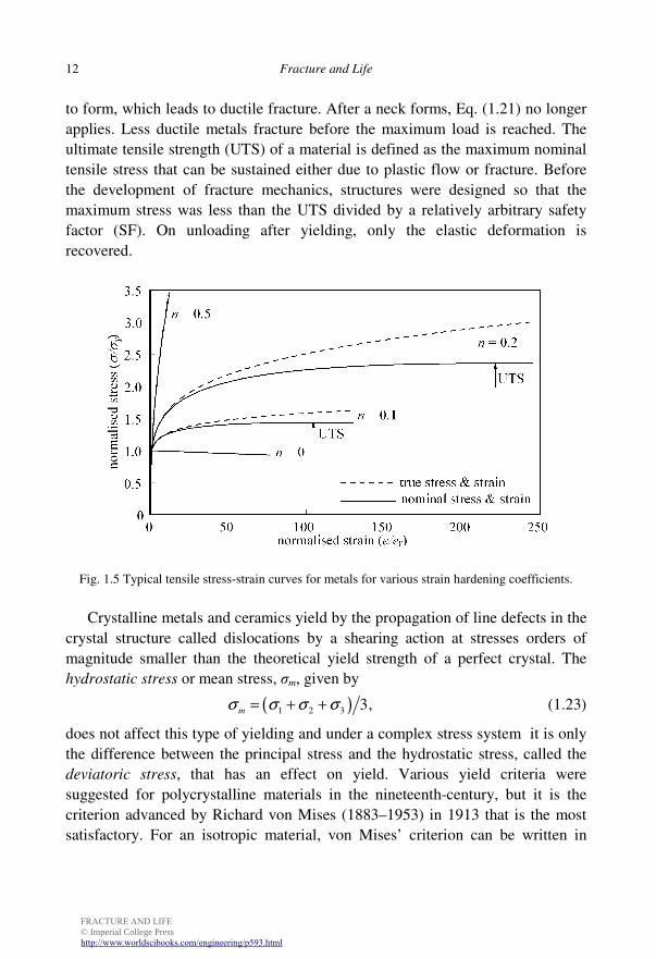
Tensile stress-strain curves with low to high strain hardening coefficients and
the idealisation of perfect plasticity where n = 0 are shown in Fig. 1.5. For ductile
metals the nominal stress reaches a maximum at a true strain e = n and a slightly
higher nominal strain ( )exp 1.nε = − At large strains greater than the strain for
the maximum nominal stress the deformation becomes localised and a neck starts
FRACTURE AND LIFE © Imperial College Presshttp://www.worldscibooks.com/engineering/p593.html
Fracture and Life 12
to form, which leads to ductile fracture. After a neck forms, Eq. (1.21) no longer
applies. Less ductile metals fracture before the maximum load is reached. The
ultimate tensile strength (UTS) of a material is defined as the maximum nominal
tensile stress that can be sustained either due to plastic flow or fracture. Before
the development of fracture mechanics, structures were designed so that the
maximum stress was less than the UTS divided by a relatively arbitrary safety
factor (SF). On unloading after yielding, only the elastic deformation is
recovered.
Fig. 1.5 Typical tensile stress-strain curves for metals for various strain hardening coefficients.
Crystalline metals and ceramics yield by the propagation of line defects in the
crystal structure called dislocations by a shearing action at stresses orders of
magnitude smaller than the theoretical yield strength of a perfect crystal. The
hydrostatic stress or mean stress, σm, given by
( )1 2 3 3,mσ σ σ σ= + + (1.23)
does not affect this type of yielding and under a complex stress system it is only
the difference between the principal stress and the hydrostatic stress, called the
deviatoric stress, that has an effect on yield. Various yield criteria were
suggested for polycrystalline materials in the nineteenth-century, but it is the
criterion advanced by Richard von Mises (1883–1953) in 1913 that is the most
satisfactory. For an isotropic material, von Mises’ criterion can be written in
FRACTURE AND LIFE © Imperial College Presshttp://www.worldscibooks.com/engineering/p593.html
Introduction and Basic Solid Mechanics 13
terms of an equivalent stress, σe, defined in terms of the three principal stresses
(σ1, σ2, σ3) by
( ) ( ) ( ){ }1
22 22
1 2 2 3 3 1 2 ,eσ σ σ σ σ σ σ = − + − + − (1.24)
with this definition yielding occurs if σe ≥ σY .Yield in polymers has a partly
viscoelastic nature and is dependent on the rate of testing and the temperature;
also it is to some extent dependent on the hydrostatic stress.
Hardness is the ability to resist indentation and in metals is measured by
pressing a standard indenter in the form of a spherical ball, or pyramid into a flat
surface. The hardness is a stress, but for historical reasons not measured on
projected area but on the surface area of the indentation. The state of stress under
an indenter has a high hydrostatic component, so that the yielding under the
indenter is highly constrained. Because of the constraint, the hardness of a metal
or ceramic is roughly three times its yield strength.
1.5 Strength Resilience and Fracture
Strength is not a fundamental property of a material. Fracture will occur in
structures made of the same material but of different geometry and size, at
different maximum stresses. A simple measure of the fracture performance of a
material under tension that is better, but still not accurate, is its resilience. The
specific resilience13 of a material is defined as the work done in stretching a
material to its breaking strength per unit volume. Although resilience is a better
indicator of the tensile performance of a material, it is still size dependent.
1.5.1 Theoretical ideal strength
The variation in bond force with interatomic separation shown in Fig. 1.1 (b) can
be transformed into a similar theoretical stress-strain relationship with the
maximum bond force becoming equivalent to the theoretical ideal strength. The
work of fracture is then the area under the stress-displacement curve and supplies
the extra energy of the fracture surfaces. Using the fact that the initial slope of
this curve is the Young’s modulus, E, a simple approximate relationship for the
theoretical ideal strength, σt, as a function of the surface energy, γ, E, and the
equilibrium atomic spacing, a0, can be obtained, which is given by
FRACTURE AND LIFE © Imperial College Presshttp://www.worldscibooks.com/engineering/p593.html
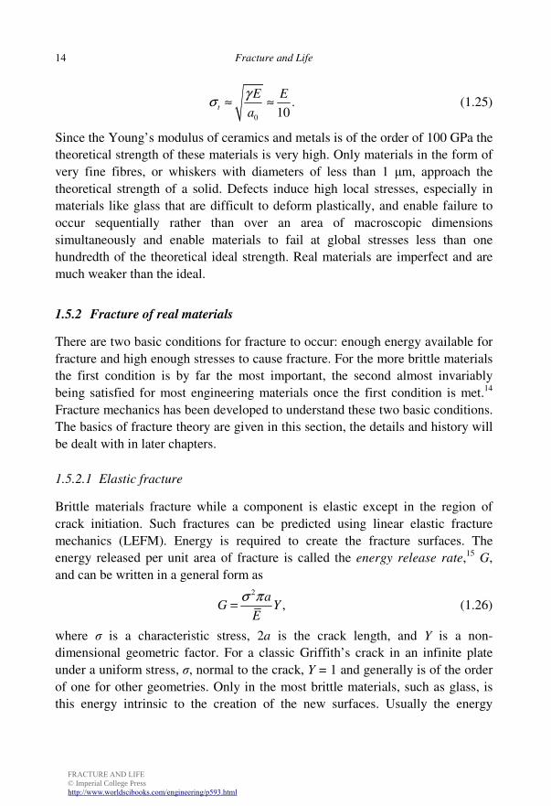
Fracture and Life 14
0
.10
t
E E
a
γσ ≈ ≈ (1.25)
Since the Young’s modulus of ceramics and metals is of the order of 100 GPa the
theoretical strength of these materials is very high. Only materials in the form of
very fine fibres, or whiskers with diameters of less than 1 µm, approach the
theoretical strength of a solid. Defects induce high local stresses, especially in
materials like glass that are difficult to deform plastically, and enable failure to
occur sequentially rather than over an area of macroscopic dimensions
simultaneously and enable materials to fail at global stresses less than one
hundredth of the theoretical ideal strength. Real materials are imperfect and are
much weaker than the ideal.
1.5.2 Fracture of real materials
There are two basic conditions for fracture to occur: enough energy available for
fracture and high enough stresses to cause fracture. For the more brittle materials
the first condition is by far the most important, the second almost invariably
being satisfied for most engineering materials once the first condition is met.14
Fracture mechanics has been developed to understand these two basic conditions.
The basics of fracture theory are given in this section, the details and history will
be dealt with in later chapters.
1.5.2.1 Elastic fracture
Brittle materials fracture while a component is elastic except in the region of
crack initiation. Such fractures can be predicted using linear elastic fracture
mechanics (LEFM). Energy is required to create the fracture surfaces. The
energy released per unit area of fracture is called the energy release rate,15 G,
and can be written in a general form as
2
,a
G YE
σ π= (1.26)
where σ is a characteristic stress, 2a is the crack length, and Y is a non-
dimensional geometric factor. For a classic Griffith’s crack in an infinite plate
under a uniform stress, σ, normal to the crack, Y = 1 and generally is of the order
of one for other geometries. Only in the most brittle materials, such as glass, is
this energy intrinsic to the creation of the new surfaces. Usually the energy
FRACTURE AND LIFE © Imperial College Presshttp://www.worldscibooks.com/engineering/p593.html
Introduction and Basic Solid Mechanics 15
extrinsic to the actual fracture process, required to deform the material non-
elastically near the tip of a fracture, is very much larger than the intrinsic energy.
In fracture mechanics the extrinsic energy is dissipated within a region around a
crack tip, which is termed the fracture process zone (FPZ). The definition of
what constitutes the FPZ varies with the type of material. For example, for
materials like high-strength aluminium alloys that are elastic except for a small
zone at the tip of the fracture the plastic zone is the FPZ, whereas for ductile
materials such as low- and medium-strength steels, where there can be
considerable plastic deformation away from the fracture tip and voids nucleate
and grow before linking up in a crack, the region of plastic void growth is the
FPZ. In fact, the definition of fracture process zone is used to suit the occasion
and is reminiscent of Humpty Dumpty’s words in Lewis Carroll’s Through the
Looking Glass: ‘When I use a word…it means just what I choose it to mean —
neither more nor less.’16 The energy consumed in the FPZ to create a unit area
fracture is the fracture energy, R. The most important of the necessary criteria for
elastic fracture is
.G R≥ (1.27)
Fractures initiated at inhomogeneities are either intrinsic ones like small micron-
sized surface flaws in glass, or extrinsic ones like notches in the object that
locally elevate the stresses. The second criterion for fracture is that the local
stress is at least equal to the cohesive strength of the material. By modelling the
deformation within the FPZ, both criteria of fracture can be included in fracture
mechanics.
In LEFM the stresses, outside of a small FPZ at the tip of a crack, decay as
the inverse of the square root of the distance, r, from the crack tip and the stresses
acting normal to the prolongation of the crack can be written as
,2
K
rσ
π= (1.28)
where K is called the stress intensity factor. The general form of K is
,K aYσ π ′= (1.29)
where Y ′ is a geometric factor. The stress intensity factor is related to energy
release rate, G, by
2
KG
E= . (1.30)
Since fracture can occur if the energy release rate, G, reaches the critical value
FRACTURE AND LIFE © Imperial College Presshttp://www.worldscibooks.com/engineering/p593.html
Fracture and Life 16
the fracture energy, R, it also occurs if the stress intensity factor reaches a critical
value, Kc, which is called the fracture toughness; the plane strain fracture
toughness is written as KIc.17 The units of the fracture toughness are MPa√m. In
the opinion of many fracture mechanists, it is the fracture energy, R, that is the
fundamental measure of the fracture resistance of a material and the fracture
toughness is a subsidiary unit. A friend of mine, Tony Atkins, states that God
would not use so daft a unit as MPa√m. Under plane strain conditions and
essentially elastic-brittle behaviour, the usual symbol for the plane strain fracture
energy, or critical energy release rate, is GIc. Provided the FPZ is small compared
to the other dimensions of a structure, especially any pre-crack or notch, then the
fracture will occur if the energy criterion is satisfied.
In the more ductile materials the fracture toughness increases with crack
growth, giving rise to what is known as crack growth resistance.
1.5.2.2 Plastic fracture
The more ductile materials deform plastically over a large region before fracture.
LEFM cannot be used to model plastic fracture. Elasto-plastic fracture
mechanics (EPFM) is more complex than LEFM and was developed after LEFM.
The FPZ is frequently large in EPFM and the second criterion of fracture that the
stress at a crack tip must exceed the cohesive strength of the material becomes
more important. If the plastic deformation is very large before fracture so that the
elastic strains can be neglected, then the mechanics of fracture at plastic collapse
becomes simpler than LEFM, as is the case in a few examples in this chapter. A
more general discussion of EPFM will be left to later chapters where it will be
introduced from a historical perspective. These more ductile materials invariably
exhibit crack growth resistance.
1.5.2.3 Size effect
Before the development of fracture mechanics, design against fracture was based
on the UTS. Such designs had no intrinsic size effect. If the dimensions of a unit
design were all scaled by a factor of two, then the safe loads predicted by such a
concept would scale by a factor of four because stress has the units of force per
unit area. If the unit design is safe and the defects that initiate the fracture are
inherent, material defects that do not scale up with the design, the doubled-up
design would be safe, providing the dimensions of the unit design were not
comparable to the size of the FPZ. However, if fracture initiated from a design
FRACTURE AND LIFE © Imperial College Presshttp://www.worldscibooks.com/engineering/p593.html
Introduction and Basic Solid Mechanics 17
detail such as a sharp re-entrant corner which scales up with the design, then the
scaled-up design on the basis of UTS is not safe. Fracture is size dependent. If
the material of the design conforms to LEFM in the unit design and the design
defect scales with the design then the safe loads for the doubled-up design are not
four times the unit load but, from Eq. (1.26), only 4/√2 = 2.83 times the unit load.
Size effect is an important aspect of fracture mechanics and will be discussed
further in later chapters.
1.5.2.4 Toughness and the characteristic length of a material
Is a material A, whose fracture energy is twice that of material B, twice as tough
as material B? The answer is that it depends upon its yield strength and Young’s
modulus. A more useful parameter for judging the toughness of a material is its
characteristic length, lch, defined by
2ch
Y
ERl
σ= . (1.31)
For materials that do not behave plastically, such as rocks, ceramics and
concrete, the tensile strength is substituted for the yield strength, in Eq. (1.31).
Classic LEFM only applies if a component or structure is large compared to the
characteristic length. The characteristic length is comparable to the length of the
FPZ and the larger it is, the better the material is at resisting fracture.
Unfortunately, for most materials the fracture energy decreases with increase in
yield strength. Without going into any design calculations, we know that if a
material’s characteristic length is comparable or larger than a characteristic
dimension of the design, then it is likely to be safe if designed on UTS. A large
concrete structure behaves in a brittle fashion and can be modelled using LEFM,
but if a laboratory-sized scale model is tested, it behaves in a more ductile
fashion because the characteristic length of concrete is of the order of a metre.
1.6 Simple Fracture Experiments
Although this chapter is necessary for those with little knowledge of solid
mechanics so that the subsequent chapters can be better understood, it is a little
dry. Thus a few simple fracture experiments are introduced at this point to make
the chapter more interesting and enable some more fracture concepts to be
presented in a painless fashion.
FRACTURE AND LIFE © Imperial College Presshttp://www.worldscibooks.com/engineering/p593.html
Fracture and Life 18
1.6.1 Paper tearing
We have all experienced trying to tear an article out of a newspaper that we wish
to save only to be frustrated by the tear not going where we want it to go, but
right through the article. Here we show that it is possible to predict the direction
of tearing in many, but not all cases. The path of a tear or fracture is not always
predictable. One of the things that fracture teaches us is that nothing is ever
perfect. A tear in a piece of paper does not follow exactly the path we predict
because of small imperfections in the paper which are unpredictable. However,
the tear path can be predicted with high accuracy if, after a small deviation from
the predicted path, the next most probable direction is back towards the original
prediction. Such tear or fracture paths are termed path stable. However, in some
cases after a small deviation from the predicted path the next most probable
direction of a tear or fracture is away from the predicted path. Such tear or
fracture paths are unstable and usually cannot be predicted over large distances
with accuracy. This section is based on an article not by an expert fracture
mechanist, but by Robert O’Keefe a science teacher at the United Nations
International School in New York who obviously has a very good grasp of
mechanics and produced an excellent article without the need to refer to a single
fracture reference.18
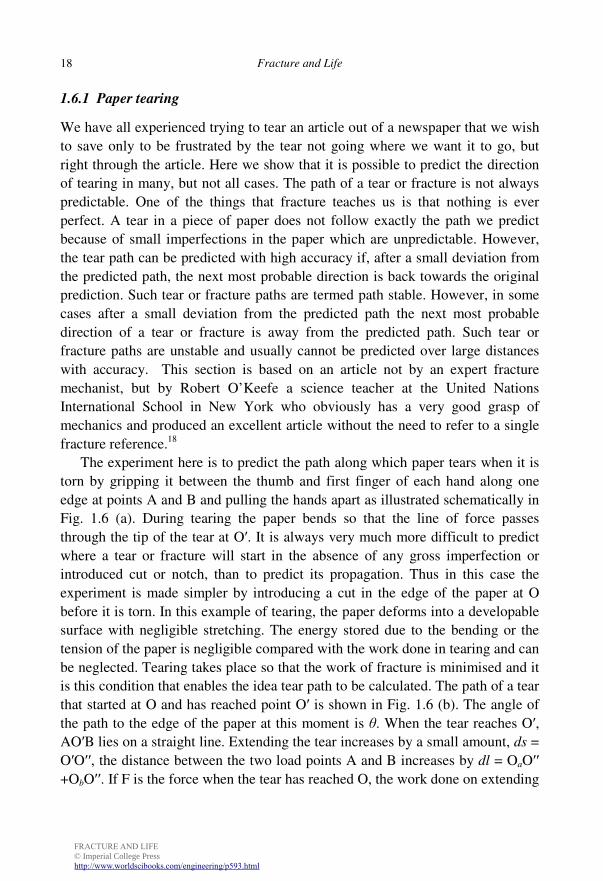
The experiment here is to predict the path along which paper tears when it is
torn by gripping it between the thumb and first finger of each hand along one
edge at points A and B and pulling the hands apart as illustrated schematically in
Fig. 1.6 (a). During tearing the paper bends so that the line of force passes
through the tip of the tear at O′. It is always very much more difficult to predict
where a tear or fracture will start in the absence of any gross imperfection or
introduced cut or notch, than to predict its propagation. Thus in this case the
experiment is made simpler by introducing a cut in the edge of the paper at O
before it is torn. In this example of tearing, the paper deforms into a developable
surface with negligible stretching. The energy stored due to the bending or the
tension of the paper is negligible compared with the work done in tearing and can
be neglected. Tearing takes place so that the work of fracture is minimised and it
is this condition that enables the idea tear path to be calculated. The path of a tear
that started at O and has reached point O′ is shown in Fig. 1.6 (b). The angle of
the path to the edge of the paper at this moment is θ. When the tear reaches O′, AO′B lies on a straight line. Extending the tear increases by a small amount, ds =
O′O′′, the distance between the two load points A and B increases by dl = OaO′′ +ObO′′. If F is the force when the tear has reached O, the work done on extending
FRACTURE AND LIFE © Imperial College Presshttp://www.worldscibooks.com/engineering/p593.html
Introduction and Basic Solid Mechanics 19
the tear by ds is given by Fdl. If the paper is isotropic in its plane, then the work
done is independent of the direction of the tear and the work is minimised if ds/dl
is minimised. It is easily shown that this condition is reached when the angle
AO′B is bisected by CO′.
Fig. 1.6 Tearing a piece of paper held between the forefingers and thumbs at A and B, the pre-cut is
at O and the current tip of the tear is at O′: (a) A 3-D view where AO′B are on a straight line. (b)
The torn paper laid flat (after O’Keefe 1994).
There are complications: machine-made paper is not isotropic and also many
papers delaminate when torn. The anisotropy in paper but not delamination can
be accommodated. The one paper still manufactured that O’Keefe recommends
that tears well contains 25% cotton,19 but you could experiment to find a suitable
alternative. Machine-made paper is more difficult to tear across the machine
direction than along it. The difference in tear toughness means that the ideal path
is not as predicted above. The tear toughness is anisotropic because the wood
fibres are partially aligned in the machine direction and it is the pull-out of these
fibres that contributes most to the tear toughness. If the toughness for tearing in
the x and y directions are Rx and Ry respectively, the toughness for a tear at an
angle θ to the x direction, Rθ, will be given reasonably accurately by
( ) ( )1
2 22cos sin .x yR R Rθ θ θ = +
(1.32)
To minimise the work done in tearing anisotropic paper Rθ(ds/dl) must be
minimised. A Fortran programme has been written that performs this
minimisation and predicts the tear path as a function of the position of the initial
cut and the anisotropy parameter, λ = Rx/Ry.20 The anisotropy parameter could be
found by measuring the tear toughness in the two directions, but is easier to
simply tear the paper from an asymmetrical initial cut and find the value of λ that
most accurately predicts the tear path. The path for a tear from any other starting
FRACTURE AND LIFE © Imperial College Presshttp://www.worldscibooks.com/engineering/p593.html
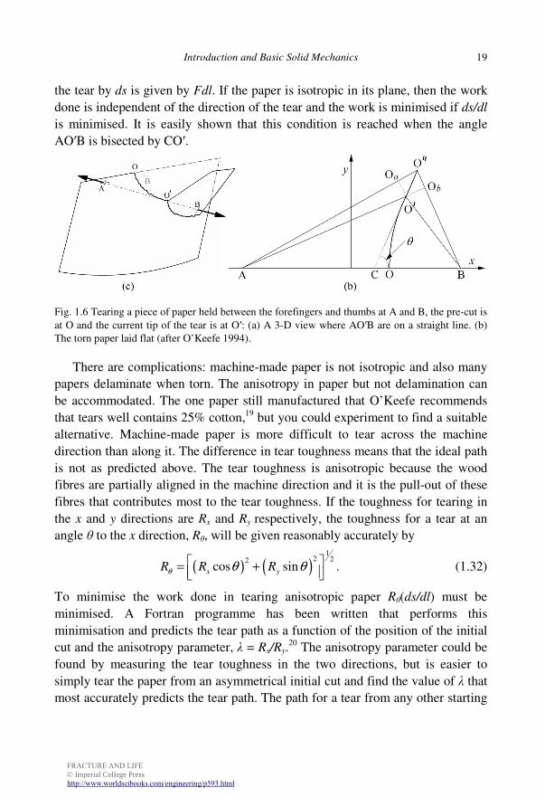
Fracture and Life 20
crack can then be predicted. The tearing paths from an initial cut located at a
quarter of the distance between the two tearing positions is shown in Fig. 1.7 for
two paper orientations and a range of values of the anisotropy parameter λ . If the
paper is anisotropic the tearing path turns away from the isotropic path towards
the machine direction.
Fig. 1.7 The tearing paths for two different paper orientations for a range of the parameter λ.
1.6.2 The sardine can problem
Sardine cans opened by keys on which the top is rolled up, or by a pulling on a
ring are scored along the edges to encourage tearing along these lines, but
sometimes the scoring is not sufficient and instead of the top tearing along the
edges an annoying convergent tear occurs. Tony Atkins has addressed this and
other similar problems, which do have more serious applications.21 Similar
convergent tears occur when stripping wallpaper from a wall and can most easily
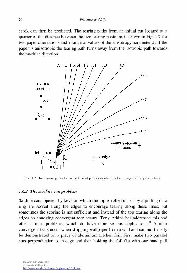
be demonstrated on a piece of aluminium kitchen foil. First make two parallel
cuts perpendicular to an edge and then holding the foil flat with one hand pull
FRACTURE AND LIFE © Imperial College Presshttp://www.worldscibooks.com/engineering/p593.html
Introduction and Basic Solid Mechanics 21
upwards on the parallel strip. Inevitably the tear will converge to a point in a
short distance (see Fig. 1.8). Converging tears can also be seen in the fuselage of
the Aloha Airways Boeing 737 which lost part of its top skin over Hawaii in
1988. Amazingly, the aeroplane did not crash and managed to land safely (see
Plate 1). The sardine can phenomenon may have prevented more of the skin of
the fuselage tearing off. The reason for the convergent tear path is that it is,
again, the path that requires the least work.
Fig. 1.8 Schematic tearing of a strip from aluminium foil.
In the previous example, any deformation in the paper was neglected and it
was assumed that all the work went into tearing. If that were the case here then a
parallel strip would result from the experiment. However, if you examine the
strip you have torn from the aluminium kitchen foil you will find it is tightly
curled because in tearing the strip the foil has been plastically bent.22 Rather
surprisingly, not only is the foil bent during tearing but also it is unbent. If you
observe the foil during tearing, the torn strip will appear straight, the curvature
only occurs elastically after the strip has been completely torn from the foil as the
imposed moment is relaxed. To analyse this problem accurately23 is difficult and
FRACTURE AND LIFE © Imperial College Presshttp://www.worldscibooks.com/engineering/p593.html
Fracture and Life 22
the simpler analysis of the key-opened sardine can without guiding scores is
offered here.21
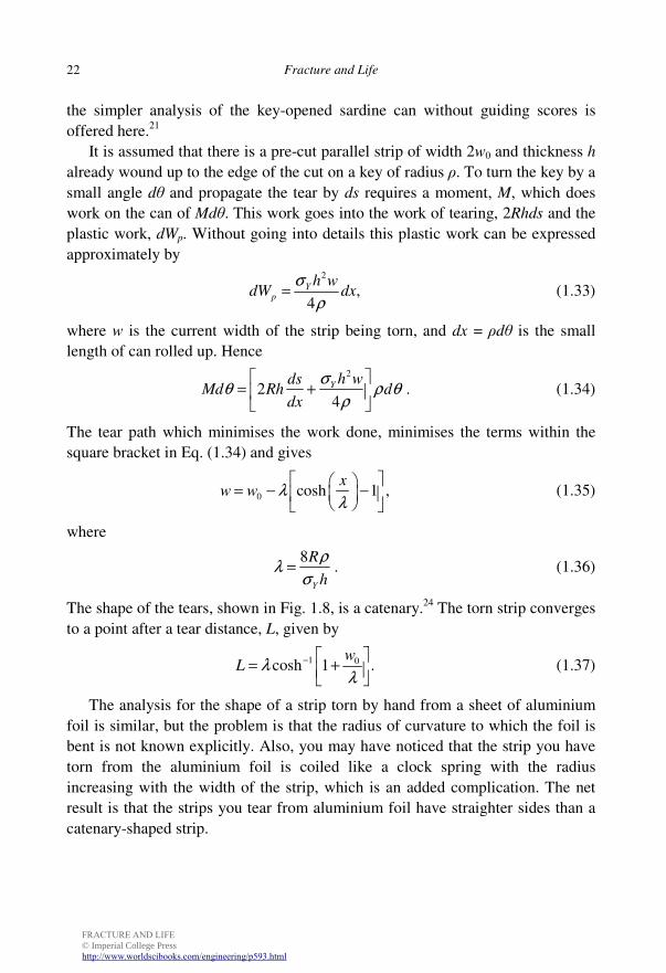
It is assumed that there is a pre-cut parallel strip of width 2w0 and thickness h
already wound up to the edge of the cut on a key of radius ρ. To turn the key by a
small angle dθ and propagate the tear by ds requires a moment, M, which does
work on the can of Mdθ. This work goes into the work of tearing, 2Rhds and the
plastic work, dWp. Without going into details this plastic work can be expressed
approximately by
2
,4Y
p
h wdW dx
σ
ρ= (1.33)
where w is the current width of the strip being torn, and dx = ρdθ is the small
length of can rolled up. Hence
2
24Y h wds
Md Rh ddx
σθ ρ θ
ρ
= +
. (1.34)
The tear path which minimises the work done, minimises the terms within the
square bracket in Eq. (1.34) and gives
0 cosh 1 ,x
w w λλ
= − −
(1.35)
where
8
Y
R
h
ρλ
σ= . (1.36)
The shape of the tears, shown in Fig. 1.8, is a catenary.24 The torn strip converges
to a point after a tear distance, L, given by
1 0cosh 1 .w
L λλ
− = +
(1.37)
The analysis for the shape of a strip torn by hand from a sheet of aluminium
foil is similar, but the problem is that the radius of curvature to which the foil is
bent is not known explicitly. Also, you may have noticed that the strip you have
torn from the aluminium foil is coiled like a clock spring with the radius
increasing with the width of the strip, which is an added complication. The net
result is that the strips you tear from aluminium foil have straighter sides than a
catenary-shaped strip.
FRACTURE AND LIFE © Imperial College Presshttp://www.worldscibooks.com/engineering/p593.html
Introduction and Basic Solid Mechanics 23
1.6.3 Divergent concertinas tears
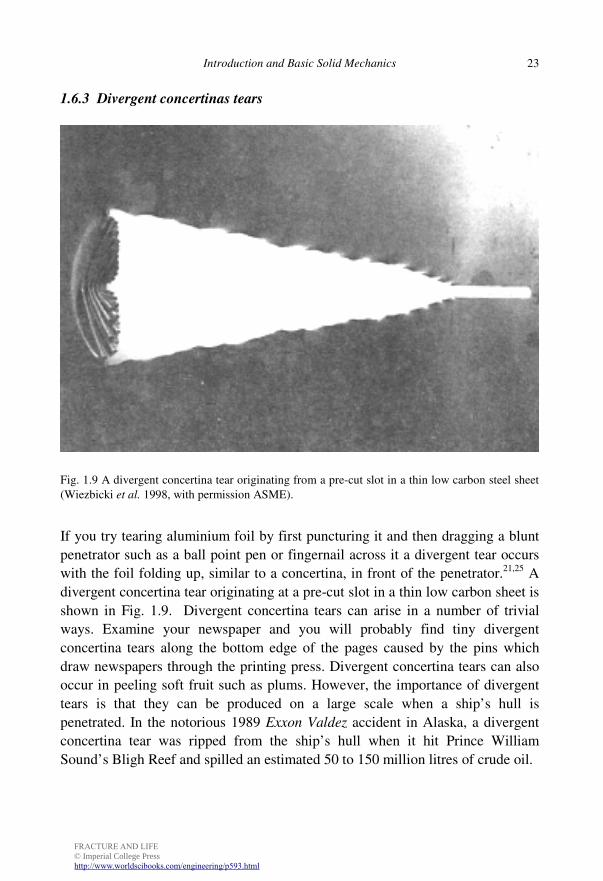
Fig. 1.9 A divergent concertina tear originating from a pre-cut slot in a thin low carbon steel sheet
(Wiezbicki et al. 1998, with permission ASME).
If you try tearing aluminium foil by first puncturing it and then dragging a blunt
penetrator such as a ball point pen or fingernail across it a divergent tear occurs
with the foil folding up, similar to a concertina, in front of the penetrator.21,25 A
divergent concertina tear originating at a pre-cut slot in a thin low carbon sheet is
shown in Fig. 1.9. Divergent concertina tears can arise in a number of trivial
ways. Examine your newspaper and you will probably find tiny divergent
concertina tears along the bottom edge of the pages caused by the pins which
draw newspapers through the printing press. Divergent concertina tears can also
occur in peeling soft fruit such as plums. However, the importance of divergent
tears is that they can be produced on a large scale when a ship’s hull is
penetrated. In the notorious 1989 Exxon Valdez accident in Alaska, a divergent
concertina tear was ripped from the ship’s hull when it hit Prince William
Sound’s Bligh Reef and spilled an estimated 50 to 150 million litres of crude oil.
FRACTURE AND LIFE © Imperial College Presshttp://www.worldscibooks.com/engineering/p593.html
Fracture and Life 24
1.6.4 Wiggly cuts or the Kit Kat® problem
There is a difference in cutting with a sharp and blunt tool. The best material to
demonstrate this difference is the thin polymer films used for food packaging.26
The easiest packaging material use for this experiment is the packaging of a bar
of Kit Kat® since the film needs to be free of contact with a hard surface and the
packaging film between the long chocolate sections of Kit Kat® is ideal for this
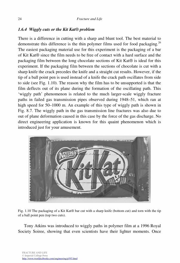
experiment. If the packaging film between the sections of chocolate is cut with a
sharp knife the crack precedes the knife and a straight cut results. However, if the
tip of a ball point pen is used instead of a knife the crack path oscillates from side
to side (see Fig. 1.10). The reason why the film has to be unsupported is that the
film deflects out of its plane during the formation of the oscillating path. This
‘wiggly path’ phenomenon is related to the much larger-scale wiggly fracture
paths in failed gas transmission pipes observed during 1948–51, which ran at
high speed for 50–1000 m. An example of this type of wiggly path is shown in
Fig. 8.7. The wiggly path in the gas transmission line fractures was also due to
out of plane deformation caused in this case by the force of the gas discharge. No
direct engineering application is known for this quaint phenomenon which is
introduced just for your amusement.
Fig. 1.10 The packaging of a Kit Kat® bar cut with a sharp knife (bottom cut) and torn with the tip
of a ball point pen (top two cuts).
Tony Atkins was introduced to wiggly paths in polymer film at a 1996 Royal
Society Soiree, showing that even scientists have their lighter moments. Once
FRACTURE AND LIFE © Imperial College Presshttp://www.worldscibooks.com/engineering/p593.html
Introduction and Basic Solid Mechanics 25
again, the fracture path is the one that minimises the work done. The size of the
oscillating paths increases with the diameter of the cutting tool and, since
packaging film is anisotropic, the details of the oscillations depend upon the
degree of anisotropy.
1.7 Concluding Remarks
The development of fracture theory has often relied on simple concepts such as
the energy necessary to produce a fracture and the minimum work concept. The
present chapter will have helped the non-specialist have enough knowledge to
appreciate the following chapters, especially Chapters two to four, where fracture
concepts are used to explain how fracture influenced the evolution of the earth’s
features, the evolution of life, and human evolution.
In most cases fracture is something to be avoided and can lead to
catastrophes, but in many other cases, such as the fashioning of stone tools,
cutting and machining the knowledge of how to produce controlled fractures has
been of great benefit.
1.8 Notes
1 The original spelling was ‘fractour’. 2 Here the notation introduced by Charles Gurney (1913–1997) for fracture energy is
used. 3 Coulomb (1785). 4 Cauchy (1823). 5 Mohr (1882). With today’s electronic calculators and computers there is little need for
graphical methods for calculations, but it would be undesirable for them to lapse into disuse because they provide an insight that cannot be given by the equations alone.
6 Jaeger and Cook (1979). 7 Christiaan Huygens (1629–1685) perfected a hair spring watch in 1675 and recruited
Oldenburg to help him get a patent in England much to the disgust of Hooke (Burgan 2007). However, Hooke himself was a difficult man.
8 Hooke (1678). 9 Young was a polymath of genius, apart from his mechanical studies, he studied
ophthalmology and identified astigmatism. He was also a distinguished linguist and produced an almost correct translation of the Rosetta stone several years before Champollion’s grammar was published, but he had to abandon Egyptology through lack of funds.
10 Young (1845). 11 Cauchy (1829). 12 Ramberg and Osgood (1943).
FRACTURE AND LIFE © Imperial College Presshttp://www.worldscibooks.com/engineering/p593.html
Fracture and Life 26
13 Sometimes called the modulus of resilience. 14 Very extensible materials like rubber and skin are exceptions as is discussed in
§3.3.1.4. 15 Irwin named this energy release rate, G, in honour of Griffith. He also used the term
crack extension force for G since the units are force per unit length. 16 The use of the term fracture process zone is explored in Chapter 9. 17 Some authors call R the fracture toughness and just call KIc the critical stress intensity
factor. 18 O’Keefe (1994). 19 Watermark Antique Laid Electronic paper, heavy weight (O’Keefe states 20 lb, but
24 lb is the weight that is still available) manufactured by Southworth Company, www.southworth.com.
20 The Fortran programme can be found at the website for this book http://www.icpress.co.uk/physics/p593.html.
21 Atkins (1995). 22 Even most paper does not tear without some plastic deformation and a strip torn from
paper will converge and will be curled. 23 Muscat-Fenech and Atkins (1994a). 24 The shape of a chain or heavy cable hanging between two supports. 25 Wierzbicki et al. (1998). 26 Atkins (2007).