Embed Size (px)
Citation preview

1
Introduction to Computer Aided Drafting
Welcome to the AutoCAD LT BBT module! You probably have several questions that you
would like answered before you start this module, for example:
What is Computer Aided Drafting (CAD)?
What is AutoCAD LT?
What will I learn by doing this module?
Let’s answer your questions:
What is Computer Aided Drafting (CAD)?
Computer Aided Drafting (referred to as CAD) is using a computer and software to draw and
design objects. A CAD system can be used to:
Draw and design parts for machines (mechanical drawing),
Design houses and structures (architectural drawing),
Design roads, highways and bridges (civil drawing),
Draw and design electronic circuits (schematic drawing),
Do two dimensional (2D) and three dimensional (3D) models.
What is AutoCAD LT?
AutoCAD LT is a CAD software package. It is one of the most widely used CAD packages
in the world. AutoCAD LT is very user friendly and virtually anyone can learn how to use it.
The AutoCAD LT interface is windows based which users will find easy to use.
What will I learn by completing this module?
By completing this module, you will learn:
How CAD works.
How to use basic CAD tools to complete drawings.
How to manipulate drawings.
The importance of CAD to industry.
Let’s get started………
2
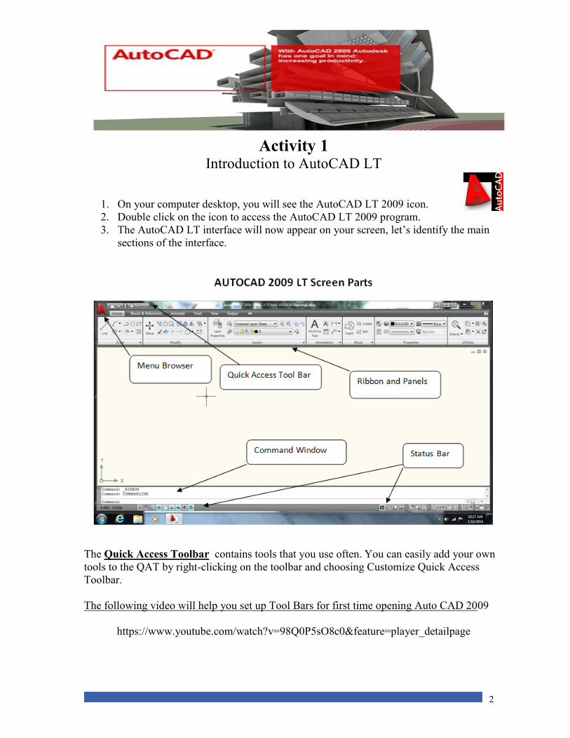
Activity 1 Introduction to AutoCAD LT
1. On your computer desktop, you will see the AutoCAD LT 2009 icon.
2. Double click on the icon to access the AutoCAD LT 2009 program.
3. The AutoCAD LT interface will now appear on your screen, let’s identify the main
sections of the interface.
The Quick Access Toolbar contains tools that you use often. You can easily add your own
tools to the QAT by right-clicking on the toolbar and choosing Customize Quick Access
Toolbar.
The following video will help you set up Tool Bars for first time opening Auto CAD 2009
https://www.youtube.com/watch?v=98Q0P5sO8c0&feature=player_detailpage
3
The Command Line
The Command Line/Window – The command window is where commands are entered and
executed in the AutoCAD LT program. We will use the command window throughout this
module. Please become familiar with the Command Line, as it will prompt you on what you
are to do next.
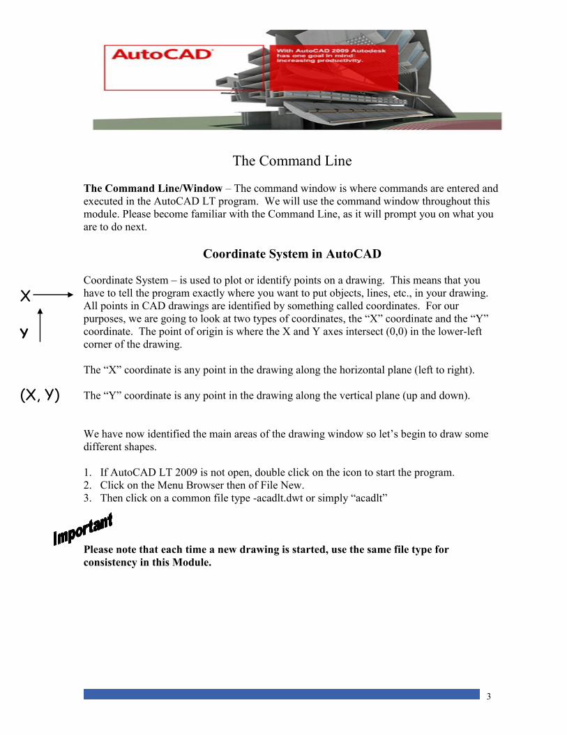
Coordinate System in AutoCAD
Coordinate System – is used to plot or identify points on a drawing. This means that you
have to tell the program exactly where you want to put objects, lines, etc., in your drawing.
All points in CAD drawings are identified by something called coordinates. For our
purposes, we are going to look at two types of coordinates, the “X” coordinate and the “Y”
coordinate. The point of origin is where the X and Y axes intersect (0,0) in the lower-left
corner of the drawing.
The “X” coordinate is any point in the drawing along the horizontal plane (left to right).
The “Y” coordinate is any point in the drawing along the vertical plane (up and down).
We have now identified the main areas of the drawing window so let’s begin to draw some
different shapes.
1. If AutoCAD LT 2009 is not open, double click on the icon to start the program.
2. Click on the Menu Browser then of File New.
3. Then click on a common file type -acadlt.dwt or simply “acadlt”
Please note that each time a new drawing is started, use the same file type for
consistency in this Module.
X
Y
(X, Y)
4
Using the Draw Toolbar
The Draw Toolbar contains the tools necessary to draw and construct objects on your
computer screen. Hint: If you take your mouse and put it over any of the buttons on the
screen, it will tell you the name of each icon.
There are two methods that can be used for drawing objects within AutoCAD LT 2009. The
first method is the free hand method. Using this method, you choose a drawing tool and
place the object you have drawn on the screen. The problem with this method is that it is not
very accurate. The second method is drawing by coordinate. This method is very accurate,
as it tells the software exactly where you want to draw an object. This is the method we will
be using.
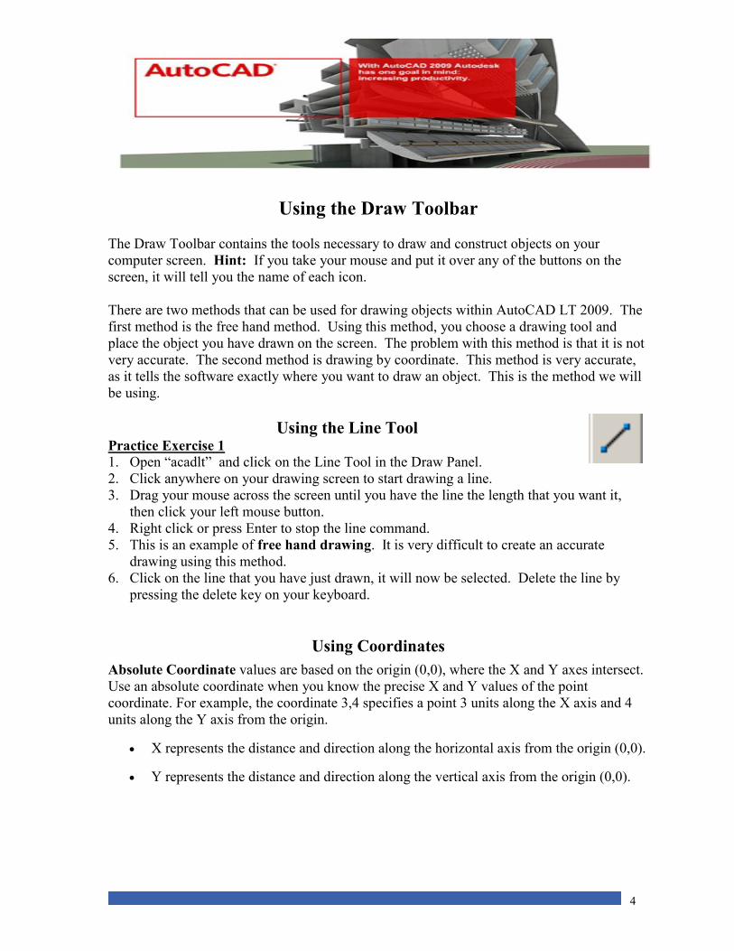
Using the Line Tool Practice Exercise 1
1. Open “acadlt” and click on the Line Tool in the Draw Panel.
2. Click anywhere on your drawing screen to start drawing a line.
3. Drag your mouse across the screen until you have the line the length that you want it,
then click your left mouse button.
4. Right click or press Enter to stop the line command.
5. This is an example of free hand drawing. It is very difficult to create an accurate
drawing using this method.
6. Click on the line that you have just drawn, it will now be selected. Delete the line by
pressing the delete key on your keyboard.
Using Coordinates
Absolute Coordinate values are based on the origin (0,0), where the X and Y axes intersect.
Use an absolute coordinate when you know the precise X and Y values of the point
coordinate. For example, the coordinate 3,4 specifies a point 3 units along the X axis and 4
units along the Y axis from the origin.
X represents the distance and direction along the horizontal axis from the origin (0,0).
Y represents the distance and direction along the vertical axis from the origin (0,0).
5
Practice Exercise 2 1. Using absolute coordinates lets draw some lines.
2. Click the line tool.
3. In the Command Window it will say Command: _line Specify first point
4. Type in 0,6 then press Enter
5. The command window will now say Specify next point.
6. Type in 80,6 and press Enter twice.
7. You have now drawn a straight line using absolute coordinates.
NOTE: If any of your drawings are not clearly visible, or if it is
small and off to the side, it can be zoomed to a new size.
Click on Quick Access Tool Bar .
“Zoom Extends . This will zoom in or out to bring your work area to full screen.
Note:. http://www.we-r-here.com/cad/tutorials/level_1/1-1.htm Is a great web site with many
tutorials and videos for helps. Go to the link read the screen, scroll to the video in “Flash” on
4 ways to draw a LINE
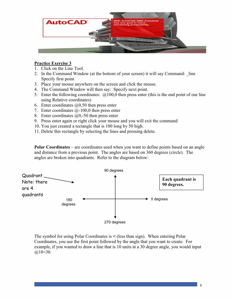
Relative Coordinates – are used to locate points on the X axis and Y axis relative to a
previous point. It’s like entering the measurement of an object. For example, if you have a
line that starts at (2,2) and you want it to finish at (7,8) you can use relative coordinates to
draw the line. It would be done like this:
(2,2) using absolute coordinates would be the starting point of the line.
If you enter the @(5,6) (relative coordinates) your line would finish at (7,8)(absolute
coordinates).
Simply, the distance between (2,2) and (7,8) is 5 units in the X direction and 6 units in the
Y direction, these are the relative coordinates.
Refer to the diagram below:
(0,0)
Origin Point
X
Y
(2,2)
@(5,6)
Line
Relative
Coordinates The @ symbol is
used when
entering
Relative
Coordinates
(@X,Y)
6
Practice Exercise 3
1. Click on the Line Tool.
2. In the Command Window (at the bottom of your screen) it will say Command: _line
Specify first point
3. Place your mouse anywhere on the screen and click the mouse.
4. The Command Window will then say: Specify next point.
5. Enter the following coordinates: @100,0 then press enter (this is the end point of our line
using Relative coordinates)
6. Enter coordinates @0,50 then press enter
7. Enter coordinates @-100,0 then press enter
8. Enter coordinates @0,-50 then press enter
9. Press enter again or right click your mouse and you will exit the command
10. You just created a rectangle that is 100 long by 50 high.
11. Delete this rectangle by selecting the lines and pressing delete.
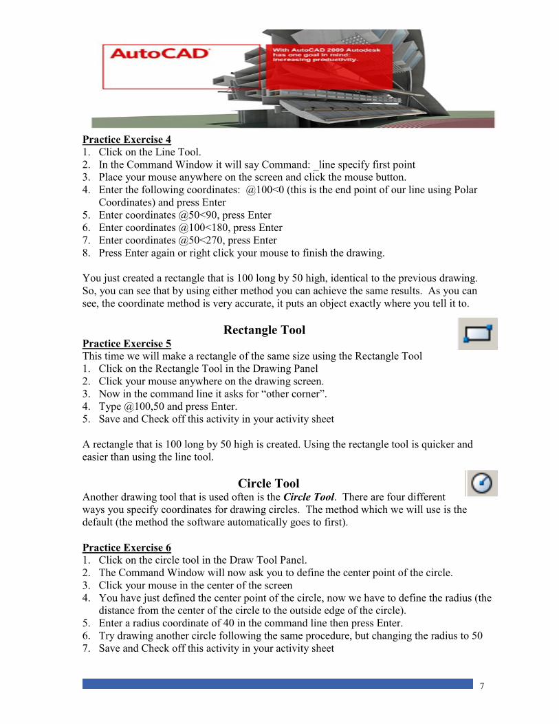
Polar Coordinates – are coordinates used when you want to define points based on an angle
and distance from a previous point. The angles are based on 360 degrees (circle). The
angles are broken into quadrants. Refer to the diagram below:
The symbol for using Polar Coordinates is < (less than sign). When entering Polar
Coordinates, you use the first point followed by the angle that you want to create. For
example, if you wanted to draw a line that is 10 units at a 30 degree angle, you would input
@10<30.
Quadrant
Note: there
are 4
quadrants
90 degrees
0 degrees 180 degrees
270 degrees
Each quadrant is
90 degrees.
7
Practice Exercise 4 1. Click on the Line Tool.
2. In the Command Window it will say Command: _line specify first point
3. Place your mouse anywhere on the screen and click the mouse button.
4. Enter the following coordinates: @100<0 (this is the end point of our line using Polar
Coordinates) and press Enter
5. Enter coordinates @50<90, press Enter
6. Enter coordinates @100<180, press Enter
7. Enter coordinates @50<270, press Enter
8. Press Enter again or right click your mouse to finish the drawing.
You just created a rectangle that is 100 long by 50 high, identical to the previous drawing.
So, you can see that by using either method you can achieve the same results. As you can
see, the coordinate method is very accurate, it puts an object exactly where you tell it to.
Rectangle Tool Practice Exercise 5 This time we will make a rectangle of the same size using the Rectangle Tool
1. Click on the Rectangle Tool in the Drawing Panel
2. Click your mouse anywhere on the drawing screen.
3. Now in the command line it asks for “other corner”.
4. Type @100,50 and press Enter.
5. Save and Check off this activity in your activity sheet
A rectangle that is 100 long by 50 high is created. Using the rectangle tool is quicker and
easier than using the line tool.
Circle Tool Another drawing tool that is used often is the Circle Tool. There are four different
ways you specify coordinates for drawing circles. The method which we will use is the
default (the method the software automatically goes to first).
Practice Exercise 6 1. Click on the circle tool in the Draw Tool Panel.
2. The Command Window will now ask you to define the center point of the circle.
3. Click your mouse in the center of the screen
4. You have just defined the center point of the circle, now we have to define the radius (the
distance from the center of the circle to the outside edge of the circle).
5. Enter a radius coordinate of 40 in the command line then press Enter.
6. Try drawing another circle following the same procedure, but changing the radius to 50
7. Save and Check off this activity in your activity sheet
8
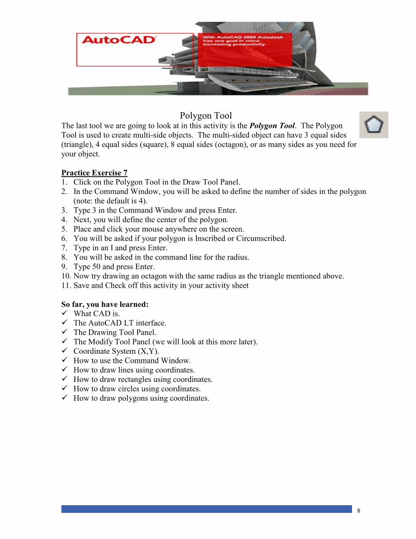
Polygon Tool The last tool we are going to look at in this activity is the Polygon Tool. The Polygon
Tool is used to create multi-side objects. The multi-sided object can have 3 equal sides
(triangle), 4 equal sides (square), 8 equal sides (octagon), or as many sides as you need for
your object.
Practice Exercise 7 1. Click on the Polygon Tool in the Draw Tool Panel.
2. In the Command Window, you will be asked to define the number of sides in the polygon
(note: the default is 4).
3. Type 3 in the Command Window and press Enter.
4. Next, you will define the center of the polygon.
5. Place and click your mouse anywhere on the screen.
6. You will be asked if your polygon is Inscribed or Circumscribed.
7. Type in an I and press Enter.
8. You will be asked in the command line for the radius.
9. Type 50 and press Enter.
10. Now try drawing an octagon with the same radius as the triangle mentioned above.
11. Save and Check off this activity in your activity sheet
So far, you have learned:
What CAD is.
The AutoCAD LT interface.
The Drawing Tool Panel.
The Modify Tool Panel (we will look at this more later).
Coordinate System (X,Y).
How to use the Command Window.
How to draw lines using coordinates.
How to draw rectangles using coordinates.
How to draw circles using coordinates.
How to draw polygons using coordinates.
9
Activity 1 Exercises
Exercise 1 1. Open a New File “acdlt”.
2. At the bottom of the window under the command line click on the OSNAP
button to turn it off.
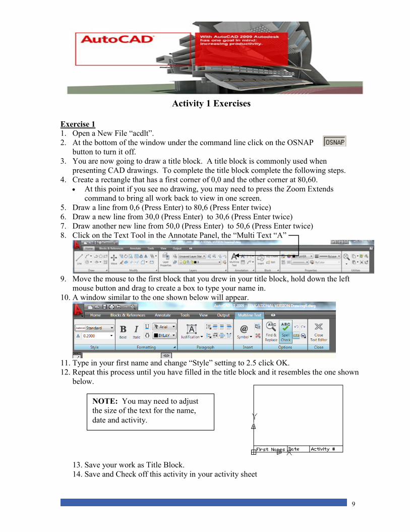
3. You are now going to draw a title block. A title block is commonly used when
presenting CAD drawings. To complete the title block complete the following steps.
4. Create a rectangle that has a first corner of 0,0 and the other corner at 80,60.
At this point if you see no drawing, you may need to press the Zoom Extends
command to bring all work back to view in one screen.
5. Draw a line from 0,6 (Press Enter) to 80,6 (Press Enter twice)
6. Draw a new line from 30,0 (Press Enter) to 30,6 (Press Enter twice)
7. Draw another new line from 50,0 (Press Enter) to 50,6 (Press Enter twice)
8. Click on the Text Tool in the Annotate Panel, the “Multi Text “A”
9. Move the mouse to the first block that you drew in your title block, hold down the left
mouse button and drag to create a box to type your name in.
10. A window similar to the one shown below will appear.
11. Type in your first name and change “Style” setting to 2.5 click OK.
12. Repeat this process until you have filled in the title block and it resembles the one shown
below.
13. Save your work as Title Block.
14. Save and Check off this activity in your activity sheet
NOTE: You may need to adjust
the size of the text for the name,
date and activity.
10
Exercise 2 1. Start AutoCAD LT 2009 if it is not already open.
2. Open New File. Make sure that OSNAP is turned on at the bottom of the screen.
3. Click on the rectangle tool and click anywhere on the screen to begin the drawing.
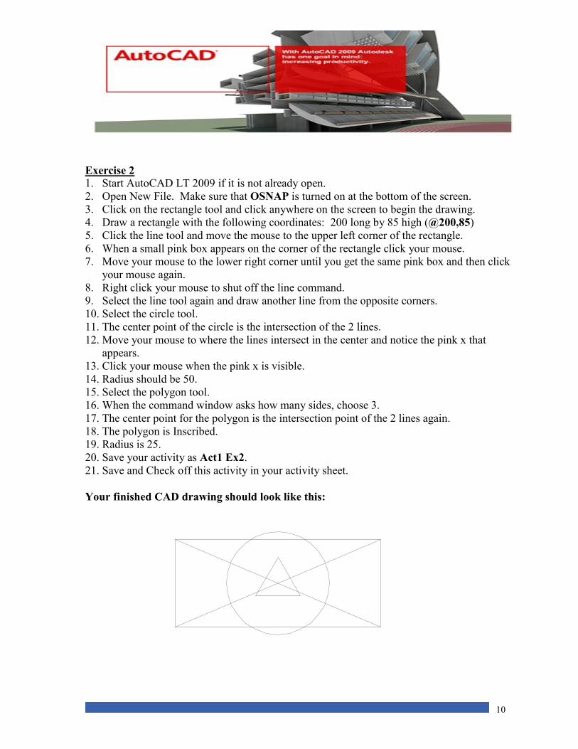
4. Draw a rectangle with the following coordinates: 200 long by 85 high (@200,85)
5. Click the line tool and move the mouse to the upper left corner of the rectangle.
6. When a small pink box appears on the corner of the rectangle click your mouse.
7. Move your mouse to the lower right corner until you get the same pink box and then click
your mouse again.
8. Right click your mouse to shut off the line command.
9. Select the line tool again and draw another line from the opposite corners.
10. Select the circle tool.
11. The center point of the circle is the intersection of the 2 lines.
12. Move your mouse to where the lines intersect in the center and notice the pink x that
appears.
13. Click your mouse when the pink x is visible.
14. Radius should be 50.
15. Select the polygon tool.
16. When the command window asks how many sides, choose 3.
17. The center point for the polygon is the intersection point of the 2 lines again.
18. The polygon is Inscribed.
19. Radius is 25.
20. Save your activity as Act1 Ex2.
21. Save and Check off this activity in your activity sheet.
Your finished CAD drawing should look like this:
11
Exercise 3 1. Open AutoCAD LT2009.
2. Open a New File
3. Save the document as Act1 Ex3 in your student folder.
4. Select Line from the Draw Panel.
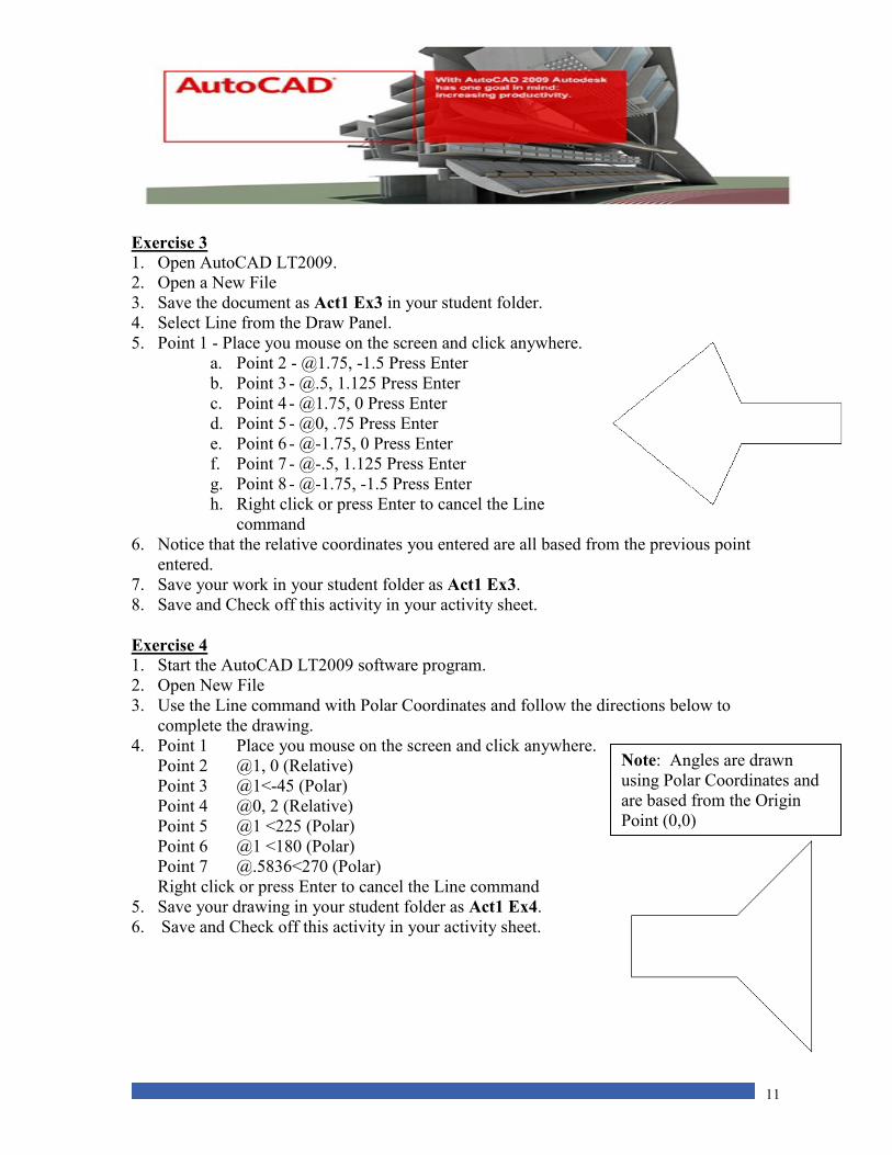
5. Point 1 - Place you mouse on the screen and click anywhere.
a. Point 2 - @1.75, -1.5 Press Enter
b. Point 3 - @.5, 1.125 Press Enter
c. Point 4 - @1.75, 0 Press Enter
d. Point 5 - @0, .75 Press Enter
e. Point 6 - @-1.75, 0 Press Enter
f. Point 7 - @-.5, 1.125 Press Enter
g. Point 8 - @-1.75, -1.5 Press Enter
h. Right click or press Enter to cancel the Line
command
6. Notice that the relative coordinates you entered are all based from the previous point
entered.
7. Save your work in your student folder as Act1 Ex3.
8. Save and Check off this activity in your activity sheet.
Exercise 4
1. Start the AutoCAD LT2009 software program.
2. Open New File
3. Use the Line command with Polar Coordinates and follow the directions below to
complete the drawing.
4. Point 1 Place you mouse on the screen and click anywhere.
Point 2 @1, 0 (Relative)
Point 3 @1<-45 (Polar)
Point 4 @0, 2 (Relative)
Point 5 @1 <225 (Polar)
Point 6 @1 <180 (Polar)
Point 7 @.5836<270 (Polar)
Right click or press Enter to cancel the Line command
5. Save your drawing in your student folder as Act1 Ex4.
6. Save and Check off this activity in your activity sheet.
Note: Angles are drawn
using Polar Coordinates and
are based from the Origin
Point (0,0)

12
Activity 1 Review Questions
1. The Modify Panel allows you to
A. Draw new objects.
B. Set coordinates.
C. To print.
D. Manipulate drawn objects.
2. Specific points in a CAD drawing are referred to as
A. Measurements.
B. Details.
C. Coordinates.
D. Specifications.
3. Any point along a horizontal plane is referred to as
A. Y.
B. X.
C. Z.
D. W.
4. The origin point in a CAD drawing is
A. (10,10).
B. (5,5).
C. (0,0).
D. (50,50).
5. This area is used for entering specific, “direct entry” details for drawing.
A. Draw Panel.
B. Command Window.
C. Modify Panel.
D. “Zoom Extends” in Quick Access tool bar.
13
Activity 2 Introduction to Object Snap
Object Snap is another feature that is available in CAD software packages. An important
feature about Object Snap is that you can connect directly to a specific point in a drawing
without knowing the coordinates. In this activity, we are going to learn how to use Object
Snap and its’ importance.
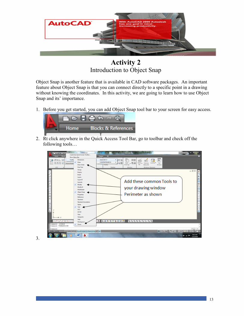
1. Before you get started, you can add Object Snap tool bar to your screen for easy access.
2. Rt click anywhere in the Quick Access Tool Bar, go to toolbar and check off the
following tools…
3.
14
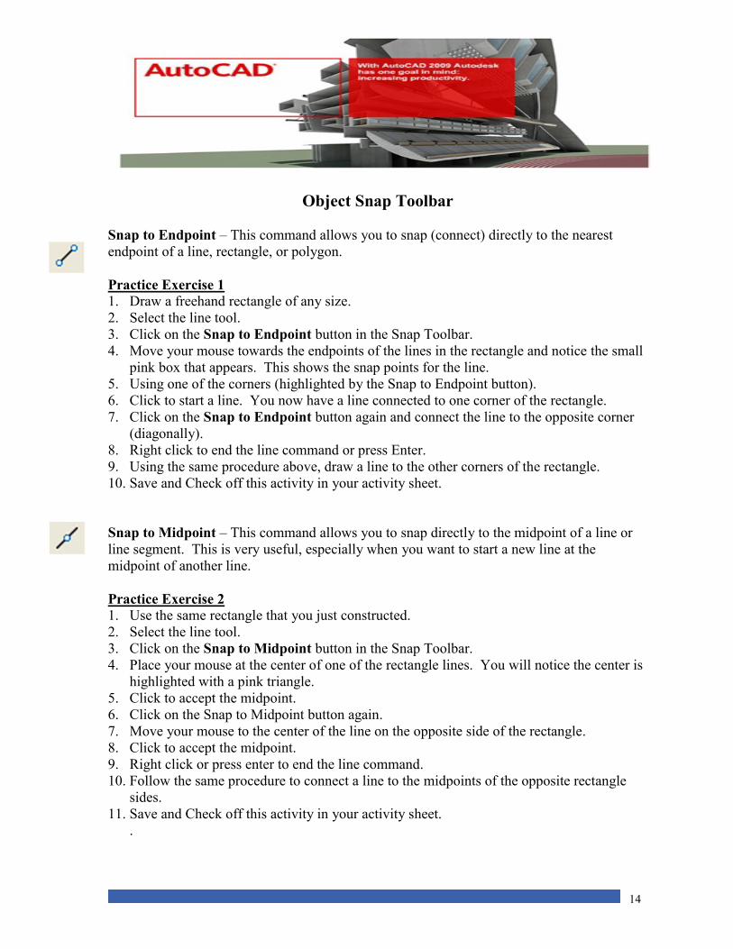
Object Snap Toolbar
Snap to Endpoint – This command allows you to snap (connect) directly to the nearest
endpoint of a line, rectangle, or polygon.
Practice Exercise 1
1. Draw a freehand rectangle of any size.
2. Select the line tool.
3. Click on the Snap to Endpoint button in the Snap Toolbar.
4. Move your mouse towards the endpoints of the lines in the rectangle and notice the small
pink box that appears. This shows the snap points for the line.
5. Using one of the corners (highlighted by the Snap to Endpoint button).
6. Click to start a line. You now have a line connected to one corner of the rectangle.
7. Click on the Snap to Endpoint button again and connect the line to the opposite corner
(diagonally).
8. Right click to end the line command or press Enter.
9. Using the same procedure above, draw a line to the other corners of the rectangle.
10. Save and Check off this activity in your activity sheet.
Snap to Midpoint – This command allows you to snap directly to the midpoint of a line or
line segment. This is very useful, especially when you want to start a new line at the
midpoint of another line.
Practice Exercise 2
1. Use the same rectangle that you just constructed.
2. Select the line tool.
3. Click on the Snap to Midpoint button in the Snap Toolbar.
4. Place your mouse at the center of one of the rectangle lines. You will notice the center is
highlighted with a pink triangle.
5. Click to accept the midpoint.
6. Click on the Snap to Midpoint button again.
7. Move your mouse to the center of the line on the opposite side of the rectangle.
8. Click to accept the midpoint.
9. Right click or press enter to end the line command.
10. Follow the same procedure to connect a line to the midpoints of the opposite rectangle
sides.
11. Save and Check off this activity in your activity sheet.
.
15
Before we move to the next snap object, we are going to clear the screen. To do this,
click on each line and press the delete key on the keyboard.
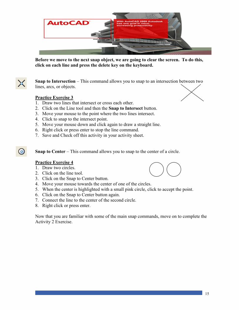
Snap to Intersection – This command allows you to snap to an intersection between two
lines, arcs, or objects.
Practice Exercise 3
1. Draw two lines that intersect or cross each other.
2. Click on the Line tool and then the Snap to Intersect button.
3. Move your mouse to the point where the two lines intersect.
4. Click to snap to the intersect point.
5. Move your mouse down and click again to draw a straight line.
6. Right click or press enter to stop the line command.
7. Save and Check off this activity in your activity sheet.
Snap to Center – This command allows you to snap to the center of a circle.
Practice Exercise 4 1. Draw two circles.
2. Click on the line tool.
3. Click on the Snap to Center button.
4. Move your mouse towards the center of one of the circles.
5. When the center is highlighted with a small pink circle, click to accept the point.
6. Click on the Snap to Center button again.
7. Connect the line to the center of the second circle.
8. Right click or press enter.
Now that you are familiar with some of the main snap commands, move on to complete the
Activity 2 Exercise.
16
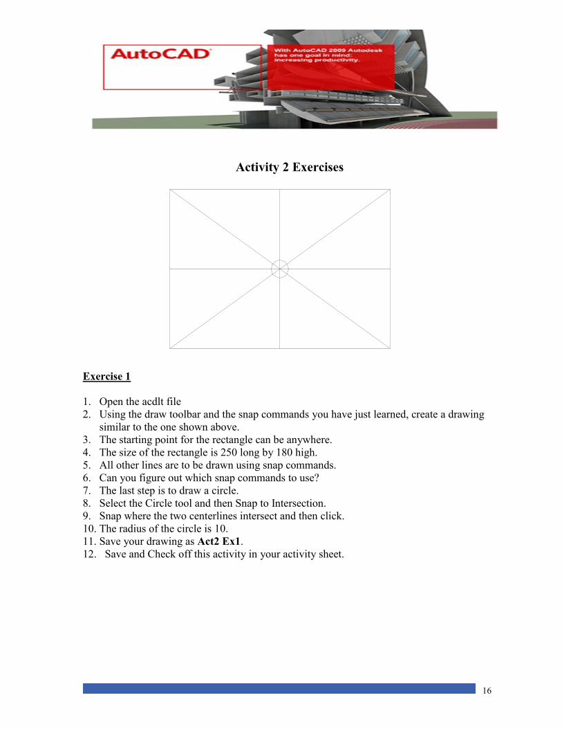
Activity 2 Exercises
Exercise 1
1. Open the acdlt file
2. Using the draw toolbar and the snap commands you have just learned, create a drawing
similar to the one shown above.
3. The starting point for the rectangle can be anywhere.
4. The size of the rectangle is 250 long by 180 high.
5. All other lines are to be drawn using snap commands.
6. Can you figure out which snap commands to use?
7. The last step is to draw a circle.
8. Select the Circle tool and then Snap to Intersection.
9. Snap where the two centerlines intersect and then click.
10. The radius of the circle is 10.
11. Save your drawing as Act2 Ex1.
12. Save and Check off this activity in your activity sheet.

17
Activity 2 Review Questions
1. The Snap toolbar can be found in the
A. Quick Access Tool Bar.
B. Insert menu.
C. View menu.
D. Modify menu.
2. Identify the Snap to Midpoint button.
A. B. C.
3. The Snap command is useful because
A. It determines drawing limits.
B. It automatically sets Z coordinates.
C. You can connect to a specific point in a drawing.
D. It always draws from (0,0).
4. An important feature about Object Snap is that you can connect directly to a specific
point in a drawing providing you know the coordinates.
A. True
B. False
5. The snap commands can only be used when drawing straight lines.
A. True
B. False
18
Activity 3 Using Trim and Extend
In this activity, you will learn how to use the Trim and Extend commands from the Modify
toolbar. The trim and extend commands allow you to modify lines, arcs and other objects
which intersect each other. This is a valuable tool and saves a lot of time when completing
drawings.
Using the Trim Command
The Trim command is used when you want to trim a line or arc that extends to the outer
limits of a geometric shape.
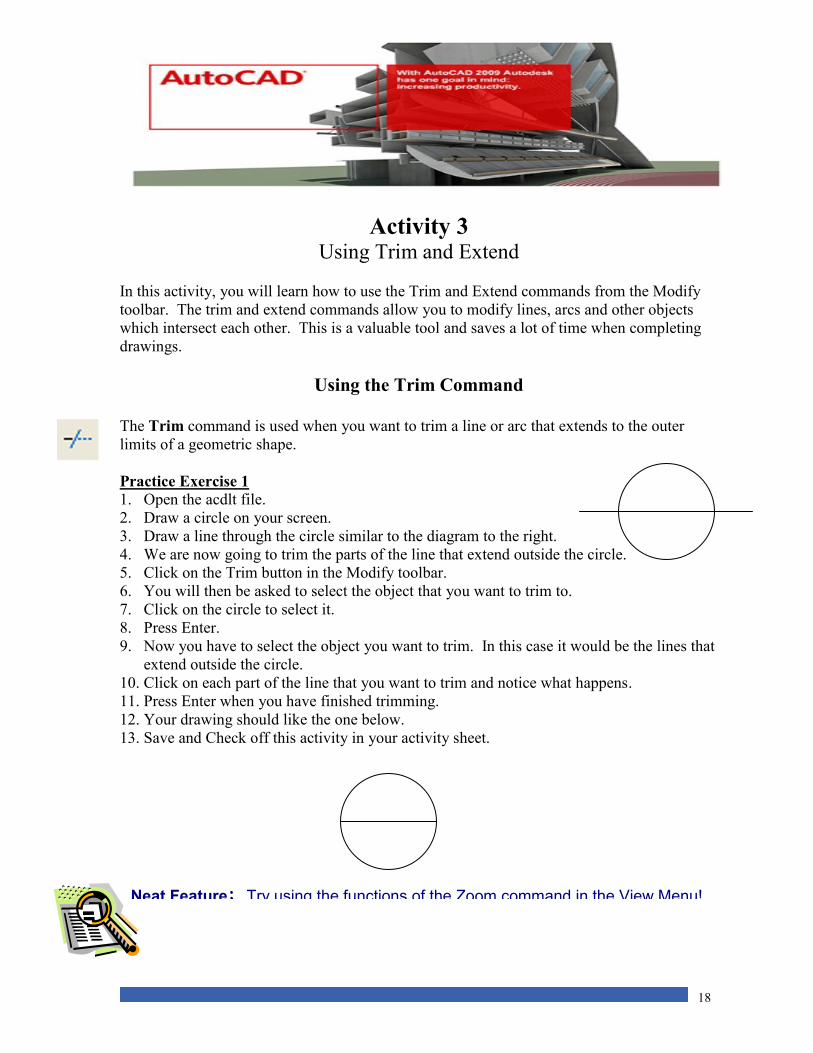
Practice Exercise 1
1. Open the acdlt file.
2. Draw a circle on your screen.
3. Draw a line through the circle similar to the diagram to the right.
4. We are now going to trim the parts of the line that extend outside the circle.
5. Click on the Trim button in the Modify toolbar.
6. You will then be asked to select the object that you want to trim to.
7. Click on the circle to select it.
8. Press Enter.
9. Now you have to select the object you want to trim. In this case it would be the lines that
extend outside the circle.
10. Click on each part of the line that you want to trim and notice what happens.
11. Press Enter when you have finished trimming.
12. Your drawing should like the one below.
13. Save and Check off this activity in your activity sheet.
Neat Feature: Try using the functions of the Zoom command in the View Menu!
19
Using The Extend Command
The Extend command is the opposite of the Trim command. The Extend is used when you
want to extend a line to an object. The extend command is a two step process, just like the
Trim command.
Practice Exercise 2 1. Open a new file
2. Draw a circle on your screen.
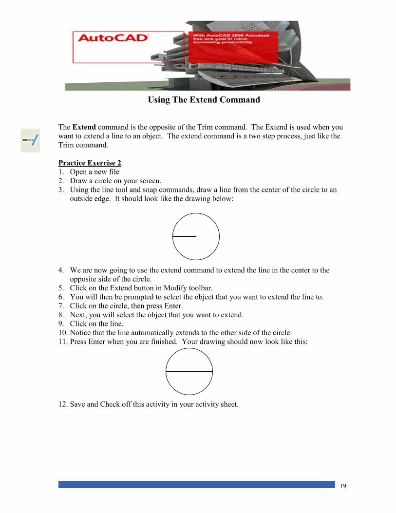
3. Using the line tool and snap commands, draw a line from the center of the circle to an
outside edge. It should look like the drawing below:
4. We are now going to use the extend command to extend the line in the center to the
opposite side of the circle.
5. Click on the Extend button in Modify toolbar.
6. You will then be prompted to select the object that you want to extend the line to.
7. Click on the circle, then press Enter.
8. Next, you will select the object that you want to extend.
9. Click on the line.
10. Notice that the line automatically extends to the other side of the circle.
11. Press Enter when you are finished. Your drawing should now look like this:
12. Save and Check off this activity in your activity sheet.
20
Activity 3 Exercises
Exercise 1 1. Make sure that the AutoCAD LT 2009 software is open.
2. Click on File and then click on Open.
3. Select Activity3PartA.dwg located in the S:/StuShare/Grade10 BBT/AutoCAD.
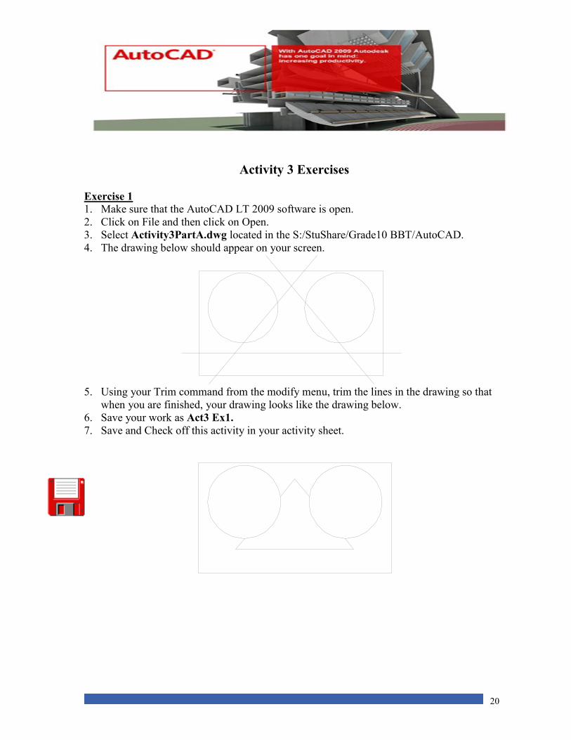
4. The drawing below should appear on your screen.
5. Using your Trim command from the modify menu, trim the lines in the drawing so that
when you are finished, your drawing looks like the drawing below.
6. Save your work as Act3 Ex1.
7. Save and Check off this activity in your activity sheet.
21
Exercise 2 1. Make sure that the AutoCAD LT 2009 software is open.
2. Click on File and then click on Open.
3. Select Activity3PartB.dwg located in the S:/StuShare/Grade10 BBT/AutoCAD.
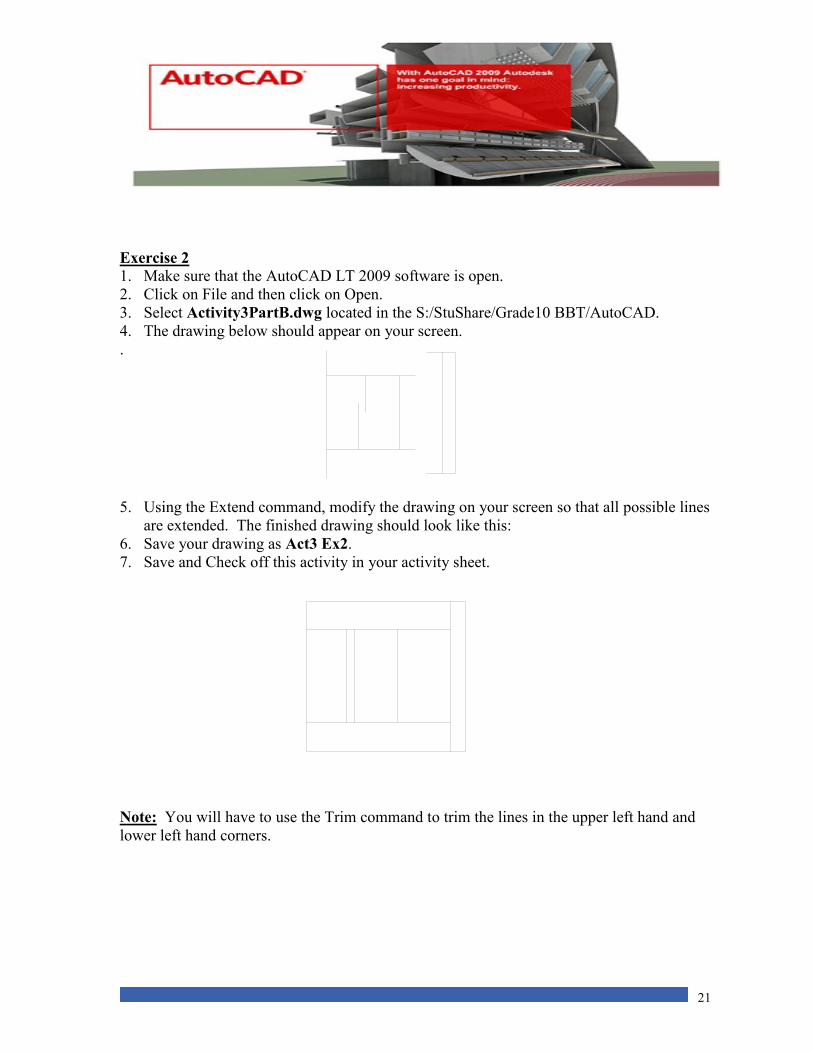
4. The drawing below should appear on your screen.
.
5. Using the Extend command, modify the drawing on your screen so that all possible lines
are extended. The finished drawing should look like this:
6. Save your drawing as Act3 Ex2.
7. Save and Check off this activity in your activity sheet.
Note: You will have to use the Trim command to trim the lines in the upper left hand and
lower left hand corners.

22
Activity 3 Review Questions
1. Using the Extend command is a
A. Three step process.
B. Four step process.
C. Single step process.
D. Two step process.
2. The ___________ command is used to remove unwanted parts of lines or arcs.
A. erase
B. extend
C. trim
D. delete
3. To Snap to the center of a line you must choose the ____________ command
A. Endpoint
B. Center
C. Midpoint
D. Intersection
4. Polar coordinates are based on:
A. 6 quadrants
B. 4 quadrants
C. 2 quadrants
D. 8 quadrants
5. This type of coordinate entry works based on a previous point of entry.
A. Point
B. Absolute
C. Polar
D. Relative
23
Activity 4 Using the Move, Copy, Erase, Rotate and Mirror Commands
Move Command The Move command allows you to move objects from a specific point on the screen to a
designated point.
Practice Exercise 1
1. Start AutoCAD LT 2009.
2. Open a New File.
3. Draw a rectangle on your screen with the following coordinates 150 long by 250 high.
4. Click on the Move button in the Modify toolbar.
5. You will be prompted to select an object.
6. Click on the rectangle and press Enter.
7. In the command window, you will see the command Base Point or Displacement.
8. This means that you need to define a point in the object, where you can pick the
object up to move it (also called a handle point).
9. The top right hand corner of the rectangle will be the Base Point.
10. Place your mouse near the top right corner of the rectangle and click to select it.
11. Notice a line is drawn from the Base Point to the rectangle that you can now move.
12. Next, you will be prompted for a second point of displacement.
13. This is the location that you want to move the object to.
14. Enter the coordinates @40,0 and press Enter.
15. The rectangle moved 40 units to the right.
16. Move the rectangle again.
17. This time use the upper left corner as the base point and move the rectangle 50 units
straight up. (@0,50)
18. Save and Check off this activity in your activity sheet.
Copy Command The Copy command allows you to copy an existing object. This command saves time,
especially when a drawing contains parts or objects which are identical. The Copy command
works very similar to the Move command.
The major difference between the Copy and Move command is once you define your second
point of displacement, a second object appears.
Note: the original object stays in the original location.
24
Note: Snap
commands
can also be
used to
define base
points or
displacement
.
Practice Exercise 2
1. Open a New file
2. Draw a circle with a radius of 40 anywhere on the screen.
3. Click on the Copy button in the Modify toolbar.
4. You will then be prompted to select the object to copy.
5. Click on the circle to select it and then press Enter.
6. Next, you will be asked to define a Base point or displacement / Multiple.
7. Snap to the center of the circle to identify this as the base point.
8. In the command line you will be asked for the second point of displacement.
9. Type @100,0.
10. A second circle appears with the centers of the circles 100 units apart.
11. Save and Check off this activity in your activity sheet.
Practice Exercise 3
You can also copy an object several times using the Multiple command.
1. Click on the Copy command.
2. Next, select the circle you first created and press enter.
3. You will be prompted for a Base point or displacement / Multiple.
4. Push M on your keyboard. The base point will be the center of the circle.
5. Place 4 more circles anywhere on the screen.
6. Save and Check off this activity in your activity sheet.
25
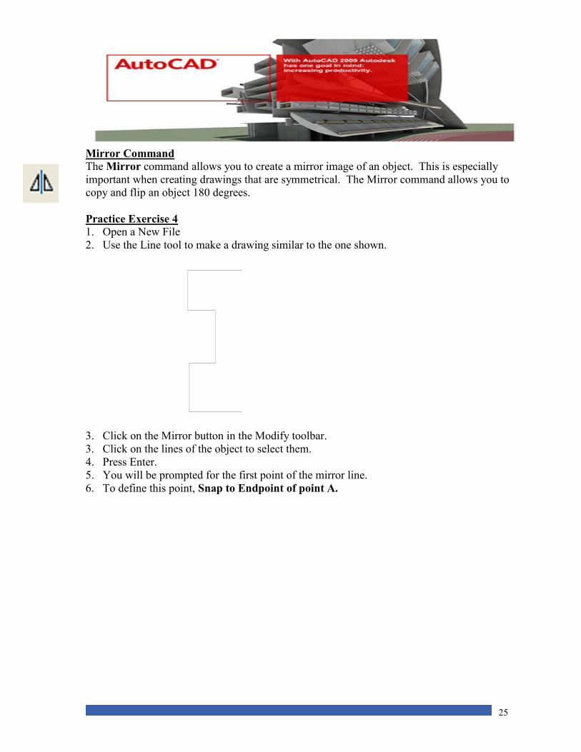
Mirror Command The Mirror command allows you to create a mirror image of an object. This is especially
important when creating drawings that are symmetrical. The Mirror command allows you to
copy and flip an object 180 degrees.
Practice Exercise 4
1. Open a New File
2. Use the Line tool to make a drawing similar to the one shown.
3. Click on the Mirror button in the Modify toolbar.
3. Click on the lines of the object to select them.
4. Press Enter.
5. You will be prompted for the first point of the mirror line.
6. To define this point, Snap to Endpoint of point A.
26
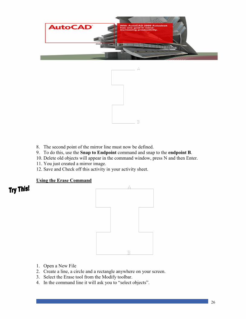
8. The second point of the mirror line must now be defined.
9. To do this, use the Snap to Endpoint command and snap to the endpoint B.
10. Delete old objects will appear in the command window, press N and then Enter.
11. You just created a mirror image.
12. Save and Check off this activity in your activity sheet.
Using the Erase Command
1. Open a New File
2. Create a line, a circle and a rectangle anywhere on your screen.
3. Select the Erase tool from the Modify toolbar.
4. In the command line it will ask you to “select objects”.
27
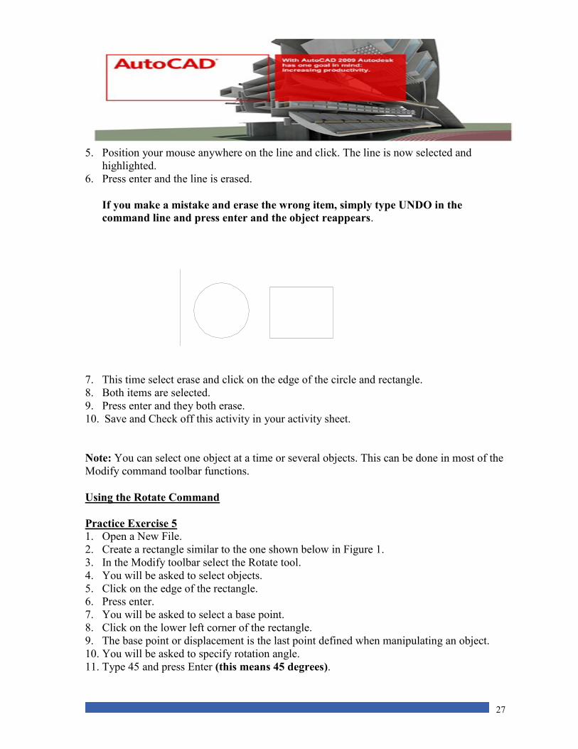
5. Position your mouse anywhere on the line and click. The line is now selected and
highlighted.
6. Press enter and the line is erased.
If you make a mistake and erase the wrong item, simply type UNDO in the
command line and press enter and the object reappears.
7. This time select erase and click on the edge of the circle and rectangle.
8. Both items are selected.
9. Press enter and they both erase.
10. Save and Check off this activity in your activity sheet.
Note: You can select one object at a time or several objects. This can be done in most of the
Modify command toolbar functions.
Using the Rotate Command
Practice Exercise 5
1. Open a New File.
2. Create a rectangle similar to the one shown below in Figure 1.
3. In the Modify toolbar select the Rotate tool.
4. You will be asked to select objects.
5. Click on the edge of the rectangle.
6. Press enter.
7. You will be asked to select a base point.
8. Click on the lower left corner of the rectangle.
9. The base point or displacement is the last point defined when manipulating an object.
10. You will be asked to specify rotation angle.
11. Type 45 and press Enter (this means 45 degrees).
28
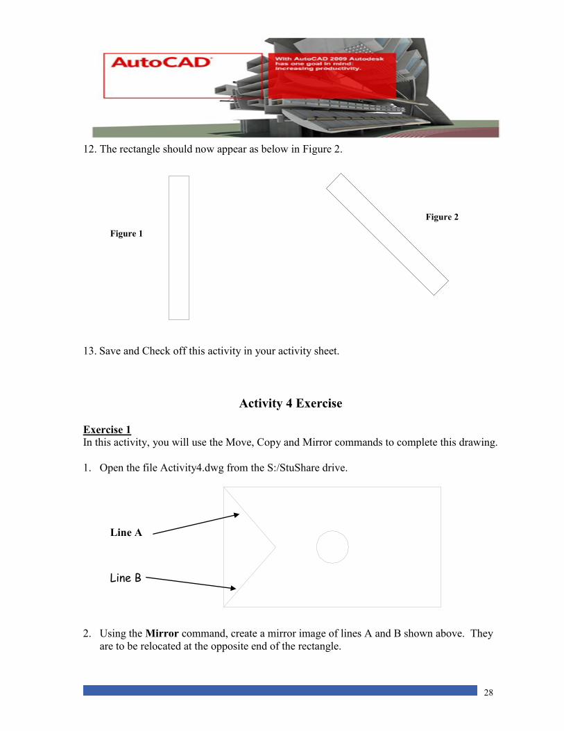
12. The rectangle should now appear as below in Figure 2.
13. Save and Check off this activity in your activity sheet.
Activity 4 Exercise
Exercise 1 In this activity, you will use the Move, Copy and Mirror commands to complete this drawing.
1. Open the file Activity4.dwg from the S:/StuShare drive.
2. Using the Mirror command, create a mirror image of lines A and B shown above. They
are to be relocated at the opposite end of the rectangle.
Figure 1
Figure 2
Line A
Line B
29
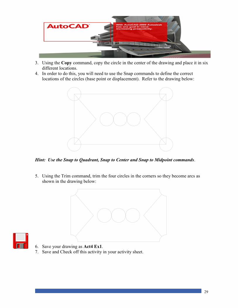
3. Using the Copy command, copy the circle in the center of the drawing and place it in six
different locations.
4. In order to do this, you will need to use the Snap commands to define the correct
locations of the circles (base point or displacement). Refer to the drawing below:
Hint: Use the Snap to Quadrant, Snap to Center and Snap to Midpoint commands.
5. Using the Trim command, trim the four circles in the corners so they become arcs as
shown in the drawing below:
6. Save your drawing as Act4 Ex1.
7. Save and Check off this activity in your activity sheet.

30
Activity 4 Review Questions
1. This command allows you to place objects in a new location:
A. Scale
B. Mirror
C. Move
D. Rotate
2. You can create the other half of a symmetrical object with this command.
A. Array
B. Move
C. Mirror
D. Copy
3. This command will allow you to connect to the outside edge of a circle.
A. Snap to Radius
B. Snap to Center
C. Snap to Edge
D. Snap to Quadrant
4. When the Mirror command is used, how many points have to be defined?
A. Four
B. Three
C. Two
D. None of the above.
31
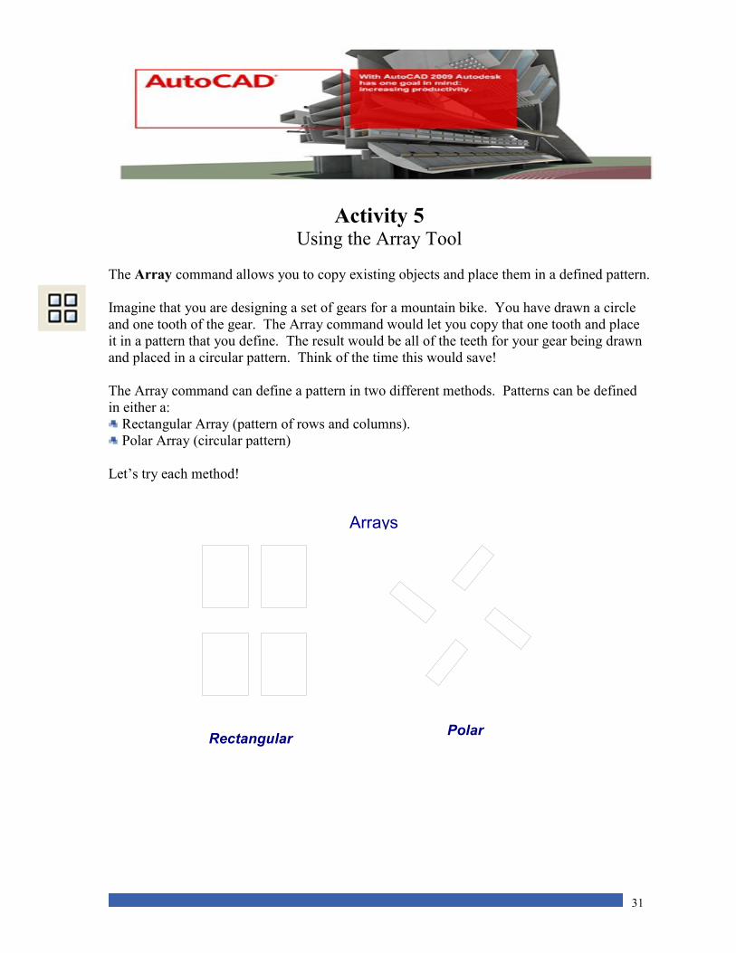
Polar
Arrays
Rectangular
Activity 5 Using the Array Tool
The Array command allows you to copy existing objects and place them in a defined pattern.
Imagine that you are designing a set of gears for a mountain bike. You have drawn a circle
and one tooth of the gear. The Array command would let you copy that one tooth and place
it in a pattern that you define. The result would be all of the teeth for your gear being drawn
and placed in a circular pattern. Think of the time this would save!
The Array command can define a pattern in two different methods. Patterns can be defined
in either a:
Rectangular Array (pattern of rows and columns).
Polar Array (circular pattern)
Let’s try each method!
32
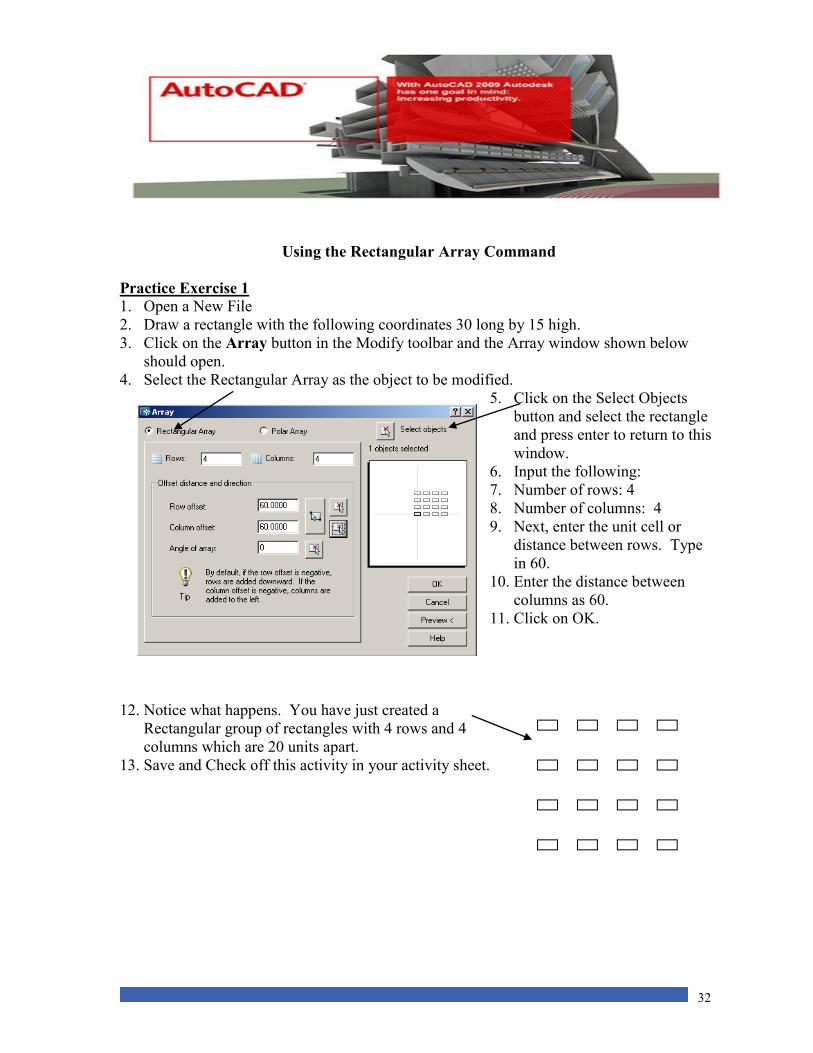
Using the Rectangular Array Command
Practice Exercise 1
1. Open a New File
2. Draw a rectangle with the following coordinates 30 long by 15 high.
3. Click on the Array button in the Modify toolbar and the Array window shown below
should open.
4. Select the Rectangular Array as the object to be modified.
5. Click on the Select Objects
button and select the rectangle
and press enter to return to this
window.
6. Input the following:
7. Number of rows: 4
8. Number of columns: 4
9. Next, enter the unit cell or
distance between rows. Type
in 60.
10. Enter the distance between
columns as 60.
11. Click on OK.
12. Notice what happens. You have just created a
Rectangular group of rectangles with 4 rows and 4
columns which are 20 units apart.
13. Save and Check off this activity in your activity sheet.
33
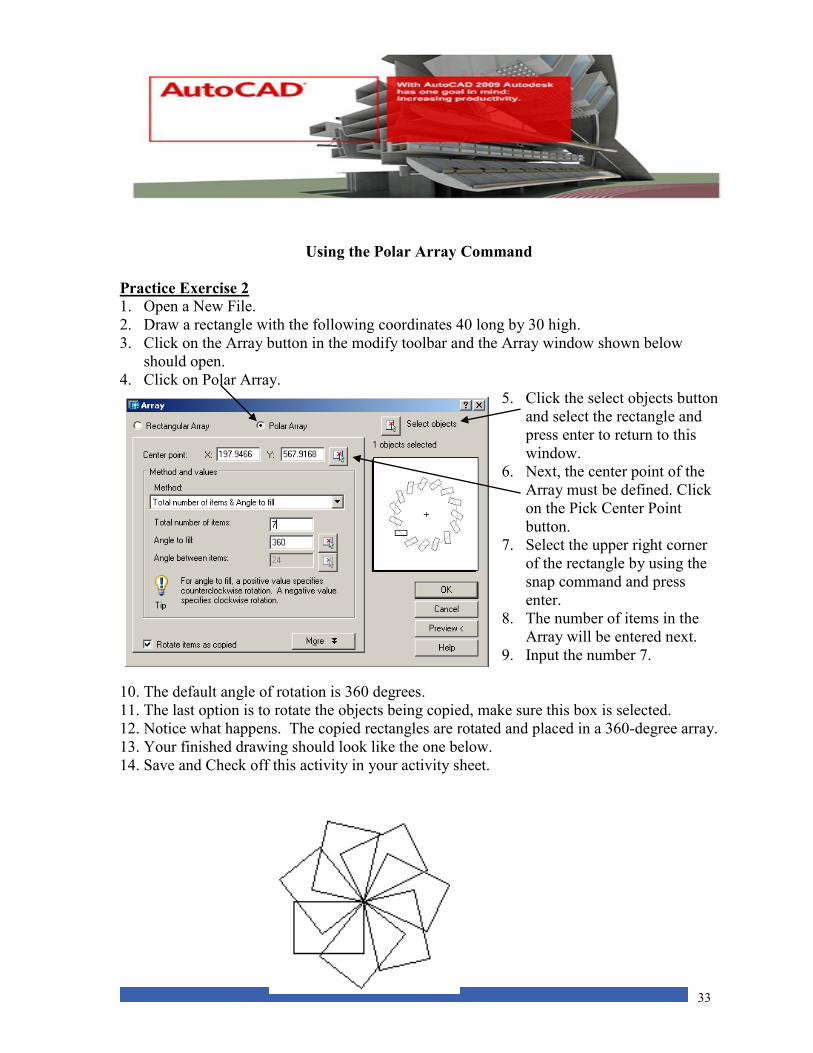
Using the Polar Array Command
Practice Exercise 2
1. Open a New File.
2. Draw a rectangle with the following coordinates 40 long by 30 high.
3. Click on the Array button in the modify toolbar and the Array window shown below
should open.
4. Click on Polar Array.
5. Click the select objects button
and select the rectangle and
press enter to return to this
window.
6. Next, the center point of the
Array must be defined. Click
on the Pick Center Point
button.
7. Select the upper right corner
of the rectangle by using the
snap command and press
enter.
8. The number of items in the
Array will be entered next.
9. Input the number 7.
10. The default angle of rotation is 360 degrees.
11. The last option is to rotate the objects being copied, make sure this box is selected.
12. Notice what happens. The copied rectangles are rotated and placed in a 360-degree array.
13. Your finished drawing should look like the one below.
14. Save and Check off this activity in your activity sheet.
34
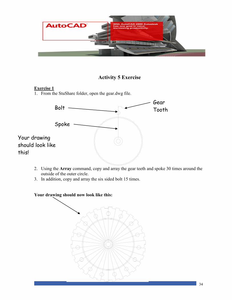
Activity 5 Exercise
Exercise 1
1. From the StuShare folder, open the gear.dwg file.
2. Using the Array command, copy and array the gear teeth and spoke 30 times around the
outside of the outer circle.
3. In addition, copy and array the six sided bolt 15 times.
Your drawing should now look like this:
Gear
Tooth Bolt
Spoke
Your drawing
should look like
this!
35
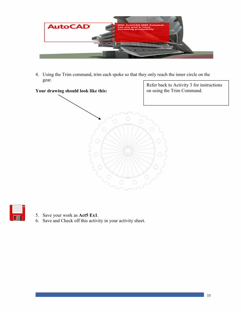
4. Using the Trim command, trim each spoke so that they only reach the inner circle on the
gear.
Your drawing should look like this:
5. Save your work as Act5 Ex1.
6. Save and Check off this activity in your activity sheet.
Refer back to Activity 3 for instructions
on using the Trim Command.

36
Activity 5 Review Questions
1. The Array button is found in the
A. Draw toolbar.
B. Snap toolbar.
C. Modify toolbar.
D. Command toolbar.
2. The are ________ different types of patterns that can be used with the Array function.
A. three
B. one
C. four
D. two
3. The cell distance between rows and columns when using the Rectangular Array
function is
A. The distance between objects.
B. The distance between objects plus the unit size of the object.
C. The combined default distance.
D. None of the above.
4. When using Polar Array, the first thing that has to be determined is
A. The width of rows and columns.
B. The number of items in the array.
C. The center point of the array.
D. The rotation angle of the array.
5. The default angle of rotation for the Polar Array command is
A. 90 degrees.
B. 360 degrees.
C. 180 degrees.
D. 270 degrees.

37
Activity 6 Career Research Project
For this project, you will watch the AutoCAD career video that is saved in the StuShare
drive. You will also use the Internet to research careers associated with AutoCAD as a
career. Prepare a one page report as outlined below.
BBT 10 Auto Cad Career Project
1. UNB Engineering is one of the largest Facilities on the campus. What are the course
selection requirements to enter UNB Engineering? (admissions Requirements)
2. Auto Cad is an important part of UNB Engineering, used in most all
programs, what are the many different programs within UNB
Engineering ? ( There are 7)
3. Name three of the many careers that use
CAD in the industry and explain one in
detail. (duties, salary and a few
interesting facts)
Be sure to put your Name on your work. Submit your final report to your teacher.
38
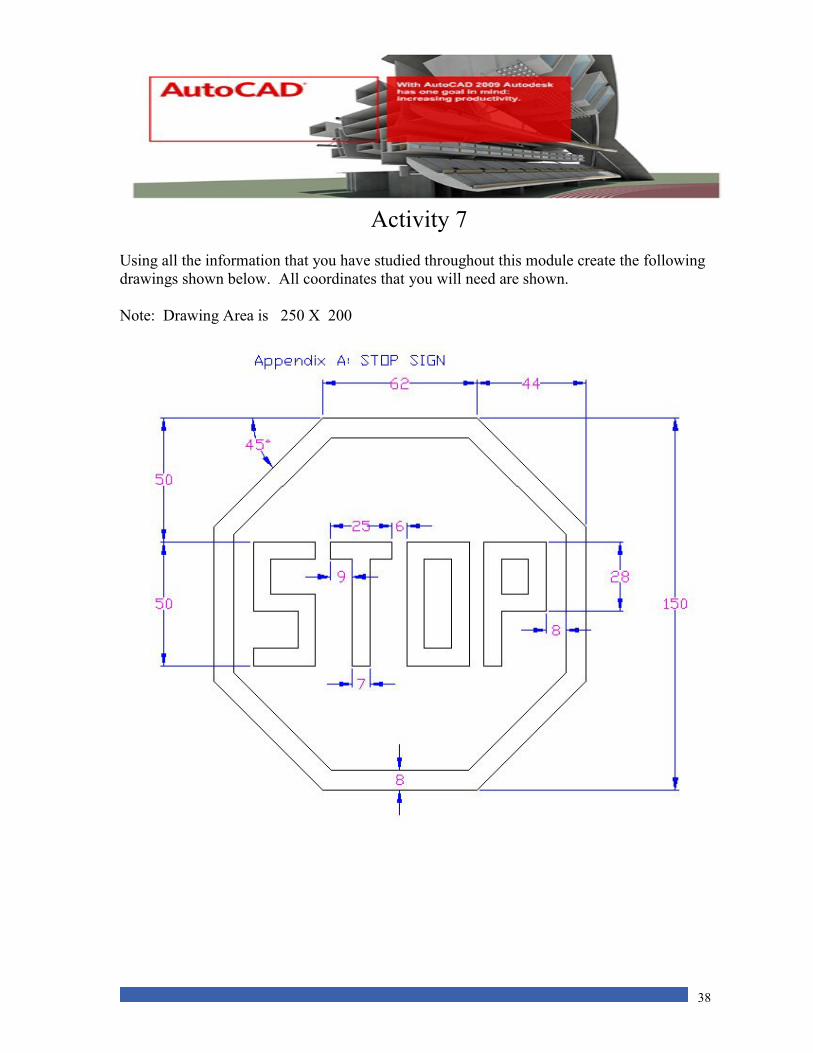
Activity 7
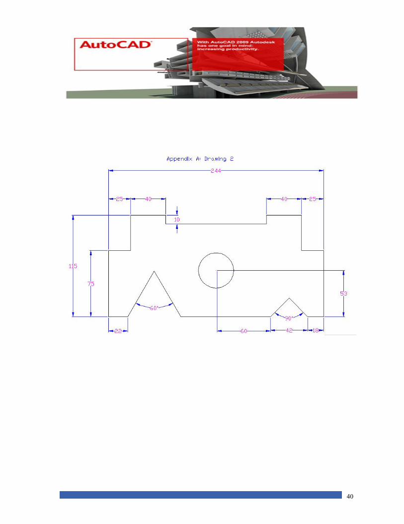
Using all the information that you have studied throughout this module create the following
drawings shown below. All coordinates that you will need are shown.
Note: Drawing Area is 250 X 200
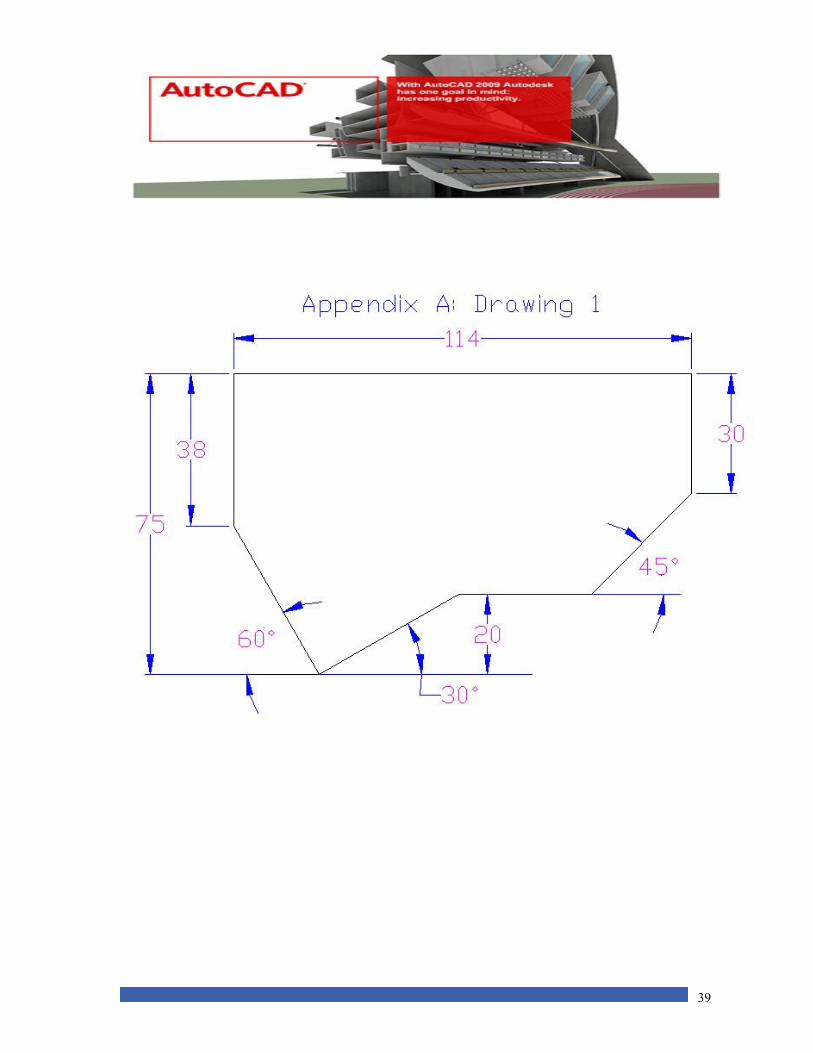
39
40
41
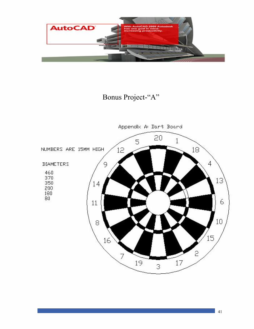
Bonus Project-“A”
42
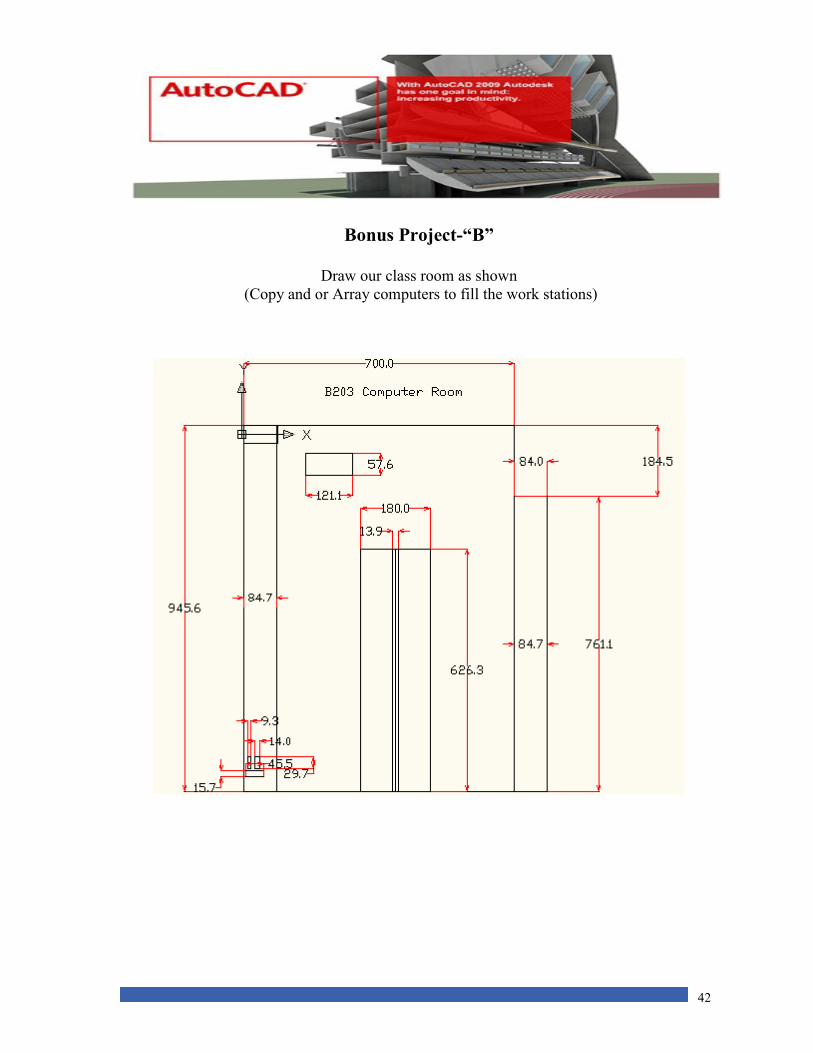
Bonus Project-“B”
Draw our class room as shown
(Copy and or Array computers to fill the work stations)