Embed Size (px)
Citation preview
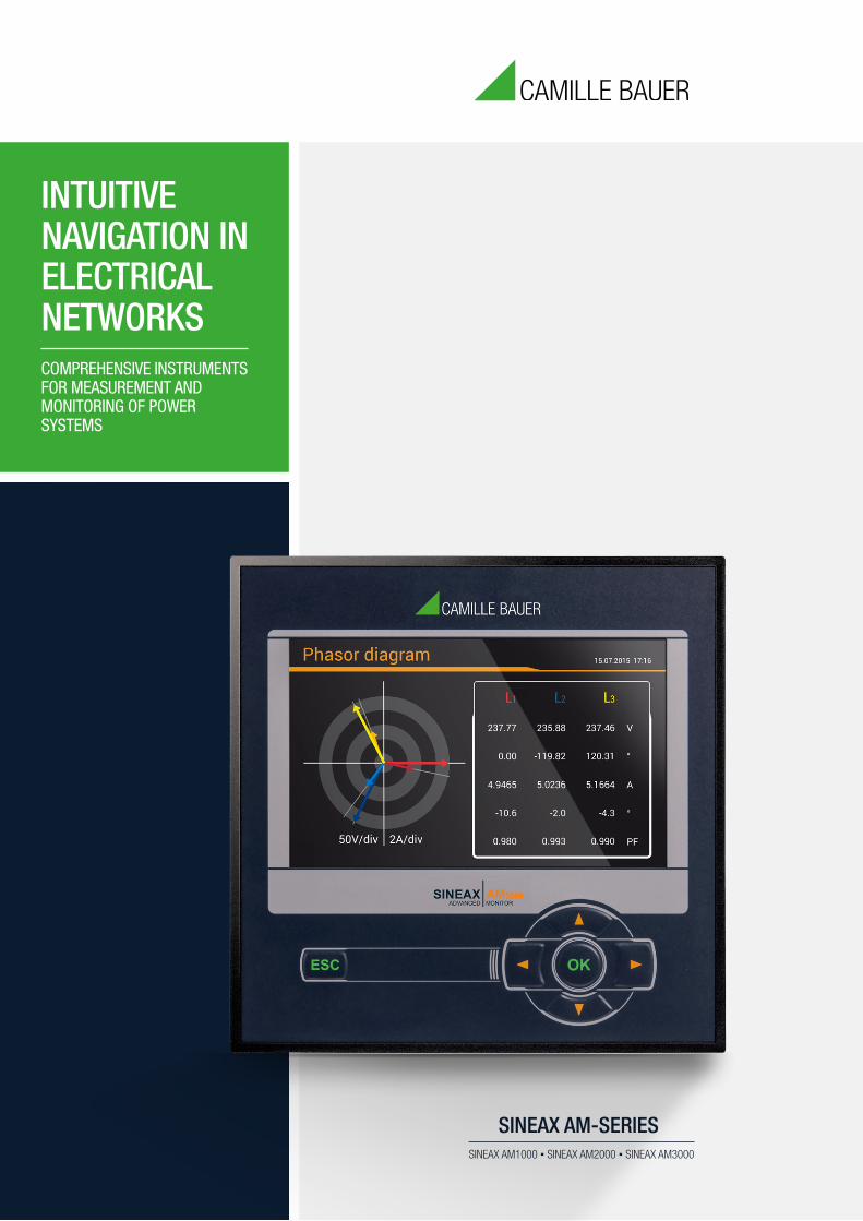
SINEAX AM-SERIESSINEAX AM1000 ▪ SINEAX AM2000 ▪ SINEAX AM3000
COMPREHENSIVE INSTRUMENTS FOR MEASUREMENT AND MONITORING OF POWER SYSTEMS
INTUITIVE NAVIGATION IN ELECTRICAL NETWORKS
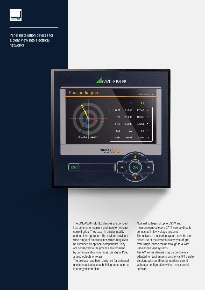
The SINEAX AM-SERIES devices are compact instruments to measure and monitor in heavy current grids. They excel in display quality and intuitive operation. The devices provide a wide range of functionalities which may even be extended by optional components. They are connected to the process environment by communication interfaces, via digital I/Os, analog outputs or relays.The devices have been designed for universal use in industrial plants, building automation or in energy distribution.
Nominal voltages of up to 690 V and measurement category CATIII can be directly connected in low voltage systems. The universal measuring system permits the direct use of the devices in any type of grid, from single-phase mains through to 4-wire unbalanced load systems. The AM series devices may be completely adapted to requirements on site via TFT display. Versions with an Ethernet interface permit webpage configuration without any special software.
Panel installation devices for a clear view into electrical networks

Easy device operation with language-specific plain text menu guidance
Topical arrangement of measured data information for quick access to desired data
Service area for maintenance and commissioning
INTUITIVE
Varied monitoring options via limit values and their logical linkage
Central alarm function via display or Webpage
Alarm list with plain-text information for a quick plant status overview
MULTIFUNCTIONAL
Universal measuring inputs for any type of grid
Freely selectable mean value and meter measuring variables
Configurable access authorisation
FLEXIBLE
Combinable device version (functionality, interfaces, I/Os, power supply)
Front dimension options (96x96 or 144x144mm)
Integration as a standard object into the SMARTCOLLECT software
SCALABLE
High resolution, colour TFT display for the pin-sharp indication of measured data
Consistently visible status information (alarms, password protection, data recording, time/date and much more)
Clear design
CLEAR
PAGE 4POWER SYSTEM MONITORING
ADVANCED MONITOR
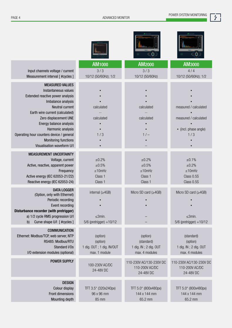
AM1000 AM2000 AM3000Input channels voltage / current 3 / 3 3 / 3 4 / 4
Measurement interval [ #cycles ] 10/12 (50/60Hz); 1/2 10/12 (50/60Hz) 10/12 (50/60Hz); 1/2
MEASURED VALUESInstantaneous values ▪ ▪ ▪
Extended reactive power analysis ▪ ▪ ▪Imbalance analysis ▪ ▪ ▪
Neutral current calculated calculated measured / calculatedEarth wire current (calculated) -- -- ▪
Zero displacement UNE calculated calculated measured / calculatedEnergy balance analysis ▪ ▪ ▪
Harmonic analysis ▪ ▪ ▪ (incl. phase angle)Operating hour counters device / general 1 / 3 1 / – 1 / 3
Monitoring functions ▪ ▪ ▪Visualisation waveform U/I ▪ – ▪
MEASUREMENT UNCERTAINTYVoltage, current ±0.2% ±0.2% ±0.1%
Active, reactive, apparent power ±0.5% ±0.5% ±0.2%Frequency ±10mHz ±10mHz ±10mHz
Active energy (IEC 62053-21/22) Class 1 Class 1 Class 0.5SReactive energy (IEC 62053-24) Class 1 Class 1 Class 0.5S
DATA LOGGER (Option, only with Ethernet)
internal (≥4GB) Micro SD card (≥4GB) Micro SD card (≥4GB)
Periodic recording ▪ ▪ ▪Event recording ▪ ▪ ▪
Disturbance recorder (with pretrigger) a) 1/2 cycle RMS progression U/I ≤3min. – ≤3min. b) Curve shape U/I [ #cycles ] 5/6 (pretrigger) +10/12 – 5/6 (pretrigger) +10/12
COMMUNICATIONEthernet: Modbus/TCP, web server, NTP (option) (option) (standard)
RS485: Modbus/RTU (option) (standard) (option)Standard I/Os 1 dig. OUT ; 1 dig. IN/OUT 1 dig. IN ; 2 dig. OUT 1 dig. IN ; 2 dig. OUT
I/O extension modules (optional) max. 1 module max. 4 modules max. 4 modules
POWER SUPPLY 100-230V AC/DC
24-48V DC
110-230V AC/130-230V DC 110-200V AC/DC
24-48V DC
110-230V AC/130-230V DC 110-200V AC/DC
24-48V DC
DESIGNColour display TFT 3.5“ (320x240px) TFT 5.0“ (800x480px) TFT 5.0“ (800x480px)
Front dimensions 96 x 96 mm 144 x 144 mm 144 x 144 mmMounting depth 85 mm 65.2 mm 65.2 mm
PAGE 5ADVANCED MONITORPOWER SYSTEM MONITORING
MEASURED VALUES
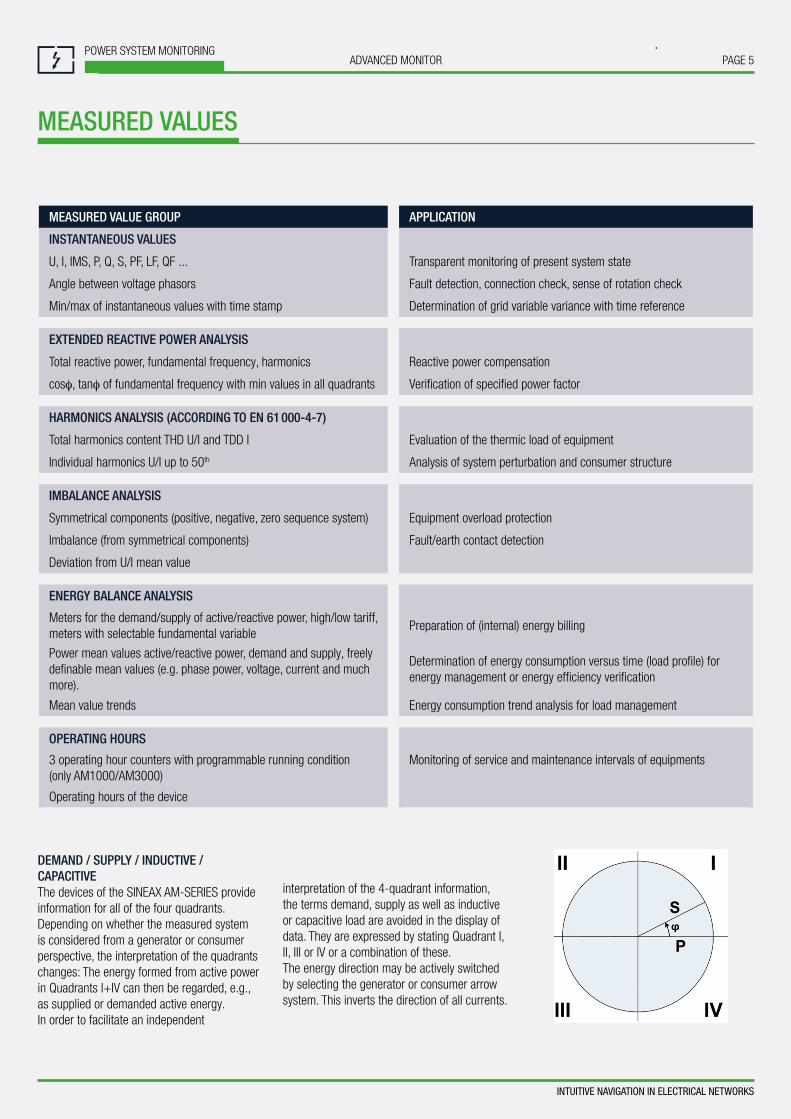
DEMAND / SUPPLY / INDUCTIVE / CAPACITIVEThe devices of the SINEAX AM-SERIES provide information for all of the four quadrants. Depending on whether the measured system is considered from a generator or consumer perspective, the interpretation of the quadrants changes: The energy formed from active power in Quadrants I+IV can then be regarded, e.g., as supplied or demanded active energy. In order to facilitate an independent
interpretation of the 4-quadrant information, the terms demand, supply as well as inductive or capacitive load are avoided in the display of data. They are expressed by stating Quadrant I, II, III or IV or a combination of these. The energy direction may be actively switched by selecting the generator or consumer arrow system. This inverts the direction of all currents.
MEASURED VALUE GROUP APPLICATION
INSTANTANEOUS VALUES
U, I, IMS, P, Q, S, PF, LF, QF ... Transparent monitoring of present system state
Angle between voltage phasors Fault detection, connection check, sense of rotation check
Min/max of instantaneous values with time stamp Determination of grid variable variance with time reference
EXTENDED REACTIVE POWER ANALYSIS
Total reactive power, fundamental frequency, harmonics Reactive power compensation
cosφ, tanφ of fundamental frequency with min values in all quadrants Verification of specified power factor
HARMONICS ANALYSIS (ACCORDING TO EN 61 000-4-7)
Total harmonics content THD U/I and TDD I Evaluation of the thermic load of equipment
Individual harmonics U/I up to 50th Analysis of system perturbation and consumer structure
IMBALANCE ANALYSIS
Symmetrical components (positive, negative, zero sequence system) Equipment overload protection
Imbalance (from symmetrical components) Fault/earth contact detection
Deviation from U/I mean value
ENERGY BALANCE ANALYSIS
Meters for the demand/supply of active/reactive power, high/low tariff, meters with selectable fundamental variable
Preparation of (internal) energy billing
Power mean values active/reactive power, demand and supply, freely definable mean values (e.g. phase power, voltage, current and much more).
Determination of energy consumption versus time (load profile) for energy management or energy efficiency verification
Mean value trends Energy consumption trend analysis for load management
OPERATING HOURS
3 operating hour counters with programmable running condition (only AM1000/AM3000)
Monitoring of service and maintenance intervals of equipments
Operating hours of the device
INTUITIVE NAVIGATION IN ELECTRICAL NETWORKS
PAGE 6POWER SYSTEM MONITORING
ADVANCED MONITOR
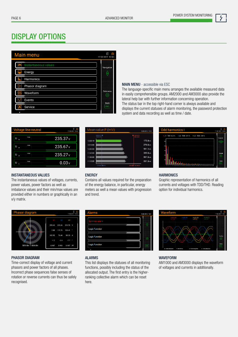
MAIN MENU - accessible via ESCThe language-specific main menu arranges the available measured data in easily comprehensible groups. AM2000 and AM3000 also provide the lateral help bar with further information concerning operation.The status bar in the top right-hand corner is always available and displays the current statuses of alarm monitoring, the password protection system and data recording as well as time / date.
DISPLAY OPTIONS
PHASOR DIAGRAMTime-correct display of voltage and current phasors and power factors of all phases. Incorrect phase sequences false senses of rotation or reverse currents can thus be safely recognised.
ALARMSThis list displays the statuses of all monitoring functions, possibly including the status of the allocated output. The first entry is the higher-ranking collective alarm which can be reset here.
INSTANTANEOUS VALUESThe instantaneous values of voltages, currents, power values, power factors as well as imbalance values and their min/max values are provided either in numbers or graphically in an x/y matrix.
ENERGYContains all values required for the preparation of the energy balance, in particular, energy meters as well a mean values with progression and trend.
HARMONICSGraphic representation of harmonics of all currents and voltages with TDD/THD. Reading option for individual harmonics.
WAVEFORMAM1000 and AM3000 displays the waveformof voltages and currents in additionally.
PAGE 7ADVANCED MONITORPOWER SYSTEM MONITORING
MONITORING AND ALARMS
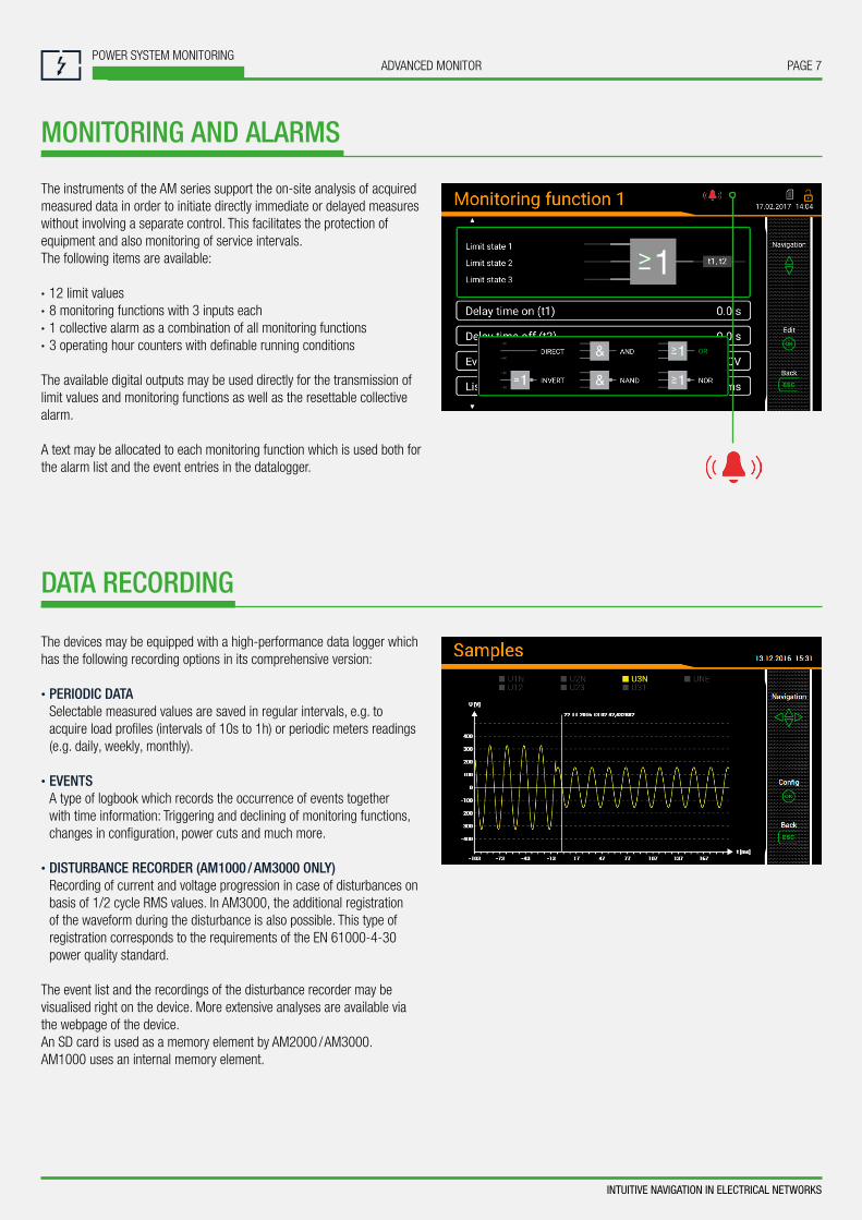
The instruments of the AM series support the on-site analysis of acquired measured data in order to initiate directly immediate or delayed measures without involving a separate control. This facilitates the protection of equipment and also monitoring of service intervals. The following items are available:
• 12 limit values• 8 monitoring functions with 3 inputs each• 1 collective alarm as a combination of all monitoring functions• 3 operating hour counters with definable running conditions
The available digital outputs may be used directly for the transmission of limit values and monitoring functions as well as the resettable collective alarm.
A text may be allocated to each monitoring function which is used both for the alarm list and the event entries in the datalogger.
DATA RECORDING
The devices may be equipped with a high-performance data logger which has the following recording options in its comprehensive version:
• PERIODIC DATA Selectable measured values are saved in regular intervals, e.g. to
acquire load profiles (intervals of 10s to 1h) or periodic meters readings (e.g. daily, weekly, monthly).
• EVENTS A type of logbook which records the occurrence of events together
with time information: Triggering and declining of monitoring functions, changes in configuration, power cuts and much more.
• DISTURBANCE RECORDER (AM1000 / AM3000 ONLY) Recording of current and voltage progression in case of disturbances on
basis of 1/2 cycle RMS values. In AM3000, the additional registration of the waveform during the disturbance is also possible. This type of registration corresponds to the requirements of the EN 61000-4-30 power quality standard.
The event list and the recordings of the disturbance recorder may be visualised right on the device. More extensive analyses are available via the webpage of the device.An SD card is used as a memory element by AM2000 / AM3000.AM1000 uses an internal memory element.
INTUITIVE NAVIGATION IN ELECTRICAL NETWORKS
PAGE 8POWER SYSTEM MONITORING
ADVANCED MONITOR
TECHNICAL DATA
INPUTSNOMINAL CURRENT 1 … 5 A (max. 7.5 A) Maximum 7.5 AOverload capacity 10 A permanent 100 A, 5x1 s, interval 300 s
NOMINAL VOLTAGE 57.7 … 400 VLN
, 100 … 693 VLL
Maximum 480 VLN
, 832 VLL
(sinusoidal)Overload capacity 480 V
LN, 832 V
LL permanent
800 VLN
, 1386 VLL
, 10x1 s, interval 10 sNominal frequency 42 … 50 … 58 Hz, 50.5 … 60 … 69.5 HzMeasurement TRMS Up to 60th harmonic
POWER SUPPLY VARIANTS Nominal voltage 100 … 230 V AC/DC (AM1000) 110 … 230 V AC, 130 … 230 V DC (AM2000/3000) 110 … 200 V AC, 110 … 200 V DC (AM2000/3000) 24 … 48 V DC (AM1000/2000/3000) Consumption ≤ 20 VA
UNINTERRUPTIBLE POWER SUPPLY (UPS)Type (3,7 V) VARTA Easy Pack EZPAckL, UL listed MH16707
TYPES OF CONNECTION Single phase or split phase (2-phase system)3 or 4-wire balanced loadOnly AM1000/AM3000: 3-wire balanced load [2U, 1I] 3-wire unbalanced load, Aron connection3 or 4-wire unbalanced load4-wire unbalanced load, Open-Y
I/O-INTERFACEANALOG OUTPUTS (optional)Linearization Linear, kinkedRange ±20 mA (24 mA max.), bipolarAccuracy ±0.2% of 20 mABurden ≤ 500 Ω (max. 10 V/20 mA)Burden influence ≤ 0.2 %Residual ripple ≤ 0.4 %
RELAYS (optional)Contacts Changeover contactLoad capacity 250 V AC, 2 A, 500 VA 30 V DC, 2 A, 60 W
DIGITAL INPUTS PASSIVENominal voltage 12/24 V DC (30 V max.)Logical ZERO –3 to +5 VLogical ONE 11 to 30 V
DIGITAL INPUTS ACTIVE (optional)Open circuit voltage ≤ 15 VShort circuit current < 15 mACurrent at RON
= 800 Ω ≥ 2 mA
DIGITAL OUTPUTS Nominal voltage 12/24 V DC (30 V max.)Nominal current 50 mA (60 mA max.)Load capacity 400 Ω … 1 MΩ
BASIC UNCERTAINTY ACCORDING IEC/EN 60688 AM1000/2000 AM3000Voltage, current ±0.2 % ±0.1 %Power ±0.5 % ±0.2 %Power factor ±0.2° ±0.1°Frequency ±0.01 HzImbalance U, I ±0.5 % Harmonic ±0.5 % THD U, I ±0.5 % Active energy Class 1 Class 0.5S (EN 62 053-22) Reactive energy Class 1 Class 0.5S (EN 62 053-24)
INTERFACESETHERNET Standard (AM3000), optional (AM1000/AM2000)Connection RJ45 socketPhysics Ethernet 100Base TXMode 10/100 MBit/s, full/half duplex, autonegotiationProtocols Modbus/TCP, http, NTP (time synchronisation)
MODBUS/RTU Standard (AM2000), optional (AM1000 / AM3000)Physics RS-485, max. 1200 m (4000 ft)Baud rate 9.6 to 115.2 kBaudNumber of participants ≤ 32
TIME REFERENCE Internal clockClock accuracy ± 2 minutes/month (15 to 30 °C)Synchronisation NTP serverPower reserve > 10 years
ENVIRONMENTAL CONDITIONS, GENERAL INFORMATIONOperating temperature without UPS: –10 up to 15 up to 30 up to + 55 °C with UPS: 0 up to 15 up to 30 up to + 35 °CStorage temperature Base device: –25 up to + 70 °C Battery pack UPS: –20 … 60 °C (<1 month) –20 … 45 °C (< 3 months) –20 … 30 °C (< 1 year)Temperature influence 0.5 x basic uncertainty per 10 KLong-term drift 0.5 x basic uncertainty per yearOthers Application group II (EN 60 688)Relative air humidity <95 % without condensationOperating altitude ≤2000 m above MSL Only to be used in buildings!
MECHANICAL PROPERTIESInstallation position Control panel installation Housing material Polycarbonate (Makrolon)Flammability class V-0 according UL94, self-extinguishing, not dripping, free of halogenWeight 800 g (AM2000/AM3000), 400 g (AM1000)
SAFETYCurrent inputs are galvanically isolated from each other.Protection class II (protective insulation, voltage inputs via protective impedance)Pollution degree 2Protection IP54 (front), IP30 (housing), IP20 (terminals)Measurement category CATIII
PAGE 9ADVANCED MONITORPOWER SYSTEM MONITORING
ORDER CODE
ORDER CODE AM1000- .... ...
1. BASIC DEVICE AM1000 6. I/O-EXTENSIONWith TFT display, for control panel installation 1 Without 0
2. INPUT | FREQUENCY RANGE 2 relays 1Current transformer inputs, 42 … 50/60 … 69.5 Hz 1 2 analog outputs, bipolar (± 20 mA) 2
3. POWER SUPPLY 4 analog outputs, bipolar (± 20 mA) 3Nominal voltage 100 … 230 V AC/DC 1 4 digital inputs passive 4Nominal voltage 24 … 48 V DC 2 4 digital inputs active 5
4. BUS CONNECTION 7. TEST PROTOCOLWithout 0 Without 0Ethernet (Modbus/TCP + web server) 1 Test protocol in German DRS485 (Modbus/RTU) 2 Test protocol in English EEthernet (Modbus/TCP + web server) + RS485 (Modbus/RTU) 3
5. DATA LOGGERWithout 0Periodic Data + events 1) 1 ACCESSORIES ARTICLE NO.Disturbance recorder + events 1) 2 Documentation CD 156 027Periodic Data + events + disturbance recorder 1) 3 Interface converter USB <> RS485 163 189
1) Datalogger only possible for device variants with Ethernet
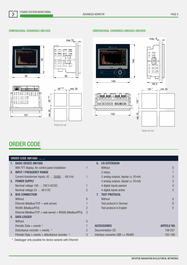
DIMENSIONAL DRAWINGS AM1000 DIMENSIONAL DRAWINGS AM2000 / AM3000
INTUITIVE NAVIGATION IN ELECTRICAL NETWORKS
Panel cut-out
Panel cut-out
92 min. 20+0,8
92+
0,8
min
. 20
138 min. 20+1
138
+1
min
. 20
PAGE 10POWER SYSTEM MONITORING
ADVANCED MONITOR
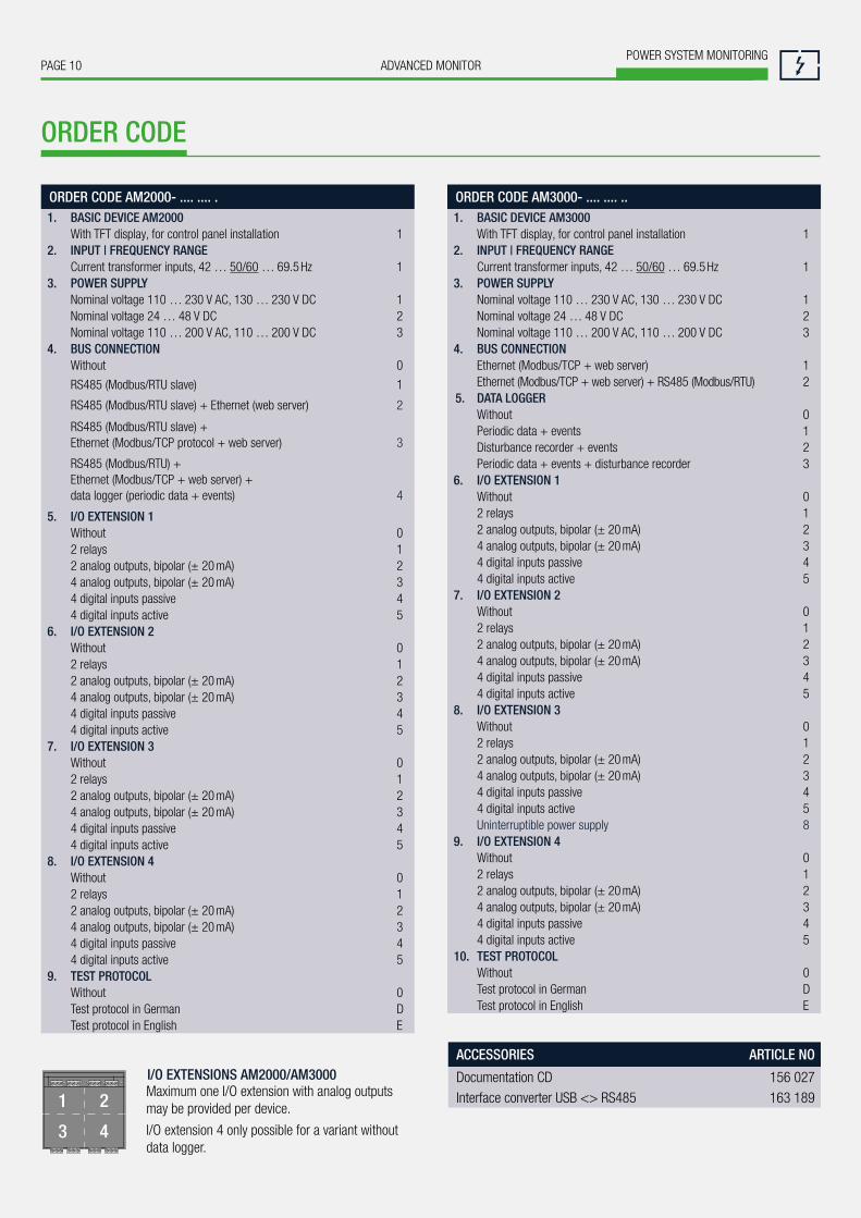
ORDER CODE AM2000- .... .... . 1. BASIC DEVICE AM2000
With TFT display, for control panel installation 1 2. INPUT | FREQUENCY RANGE
Current transformer inputs, 42 … 50/60 … 69.5 Hz 1 3. POWER SUPPLY
Nominal voltage 110 … 230 V AC, 130 … 230 V DC 1Nominal voltage 24 … 48 V DC 2Nominal voltage 110 … 200 V AC, 110 … 200 V DC 3
4. BUS CONNECTIONWithout 0
RS485 (Modbus/RTU slave) 1
RS485 (Modbus/RTU slave) + Ethernet (web server) 2
RS485 (Modbus/RTU slave) + Ethernet (Modbus/TCP protocol + web server) 3
RS485 (Modbus/RTU) + Ethernet (Modbus/TCP + web server) + data logger (periodic data + events) 4
5. I/O EXTENSION 1Without 02 relays 12 analog outputs, bipolar (± 20 mA) 24 analog outputs, bipolar (± 20 mA) 34 digital inputs passive 44 digital inputs active 5
6. I/O EXTENSION 2Without 02 relays 12 analog outputs, bipolar (± 20 mA) 24 analog outputs, bipolar (± 20 mA) 34 digital inputs passive 44 digital inputs active 5
7. I/O EXTENSION 3Without 02 relays 12 analog outputs, bipolar (± 20 mA) 24 analog outputs, bipolar (± 20 mA) 34 digital inputs passive 44 digital inputs active 5
8. I/O EXTENSION 4Without 02 relays 12 analog outputs, bipolar (± 20 mA) 24 analog outputs, bipolar (± 20 mA) 34 digital inputs passive 44 digital inputs active 5
9. TEST PROTOCOLWithout 0Test protocol in German DTest protocol in English E
Maximum one I/O extension with analog outputs may be provided per device.
I/O extension 4 only possible for a variant without data logger.
I/O EXTENSIONS AM2000/AM3000
ORDER CODE
ACCESSORIES ARTICLE NO
Documentation CD 156 027Interface converter USB <> RS485 163 189
ORDER CODE AM3000- .... .... .. 1. BASIC DEVICE AM3000
With TFT display, for control panel installation 1 2. INPUT | FREQUENCY RANGE
Current transformer inputs, 42 … 50/60 … 69.5 Hz 1 3. POWER SUPPLY
Nominal voltage 110 … 230 V AC, 130 … 230 V DC 1Nominal voltage 24 … 48 V DC 2Nominal voltage 110 … 200 V AC, 110 … 200 V DC 3
4. BUS CONNECTIONEthernet (Modbus/TCP + web server) 1Ethernet (Modbus/TCP + web server) + RS485 (Modbus/RTU) 2
5. DATA LOGGERWithout 0Periodic data + events 1Disturbance recorder + events 2Periodic data + events + disturbance recorder 3
6. I/O EXTENSION 1Without 02 relays 12 analog outputs, bipolar (± 20 mA) 24 analog outputs, bipolar (± 20 mA) 34 digital inputs passive 44 digital inputs active 5
7. I/O EXTENSION 2Without 02 relays 12 analog outputs, bipolar (± 20 mA) 24 analog outputs, bipolar (± 20 mA) 34 digital inputs passive 44 digital inputs active 5
8. I/O EXTENSION 3Without 02 relays 12 analog outputs, bipolar (± 20 mA) 24 analog outputs, bipolar (± 20 mA) 34 digital inputs passive 44 digital inputs active 5Uninterruptible power supply 8
9. I/O EXTENSION 4Without 02 relays 12 analog outputs, bipolar (± 20 mA) 24 analog outputs, bipolar (± 20 mA) 34 digital inputs passive 44 digital inputs active 5
10. TEST PROTOCOLWithout 0Test protocol in German DTest protocol in English E
PAGE 11ADVANCED MONITORPOWER SYSTEM MONITORING
INTUITIVE NAVIGATION IN ELECTRICAL NETWORKS
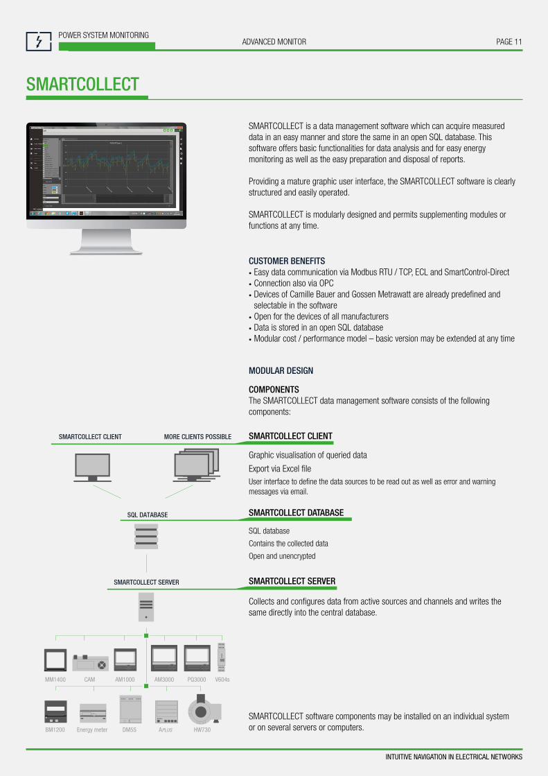
SMARTCOLLECT
AM1000 AM3000 PQ3000MM1400
BM1200
MORE CLIENTS POSSIBLESMARTCOLLECT CLIENT
SQL DATABASE
SMARTCOLLECT SERVER
Energy meter
SMARTCOLLECT is a data management software which can acquire measured data in an easy manner and store the same in an open SQL database. This software offers basic functionalities for data analysis and for easy energy monitoring as well as the easy preparation and disposal of reports.
Providing a mature graphic user interface, the SMARTCOLLECT software is clearly structured and easily operated.
SMARTCOLLECT is modularly designed and permits supplementing modules or functions at any time.
CUSTOMER BENEFITS • Easy data communication via Modbus RTU / TCP, ECL and SmartControl-Direct • Connection also via OPC • Devices of Camille Bauer and Gossen Metrawatt are already predefined and selectable in the software
• Open for the devices of all manufacturers • Data is stored in an open SQL database • Modular cost / performance model – basic version may be extended at any time
MODULAR DESIGN
COMPONENTSThe SMARTCOLLECT data management software consists of the following components:
SMARTCOLLECT CLIENT
Graphic visualisation of queried data
Export via Excel fileUser interface to define the data sources to be read out as well as error and warning messages via email.
SMARTCOLLECT DATABASE
SQL database
Contains the collected data
Open and unencrypted
SMARTCOLLECT SERVER
Collects and configures data from active sources and channels and writes the same directly into the central database.
SMARTCOLLECT software components may be installed on an individual system or on several servers or computers.

Camille Bauer Metrawatt AGAargauerstrasse 7 ▪ 5610 Wohlen ▪ SwitzerlandTEL +41 56 618 21 11 ▪ FAX +41 56 618 21 21
www.camillebauer.com ▪ [email protected] Subj
ect t
o ch
ange
with
out n
otic
e ▪
SM
-103
6-00
0-07
-EN-
02.1
7