Embed Size (px)
Citation preview
Operating Instructions
Date Name No. 4078.BGD enIssued: 02.12.03 hün/Obs Page 1/47 pages Revision: 28.11.2016 MSch Checked: 28.11.2016 SLAN
INVERTRONIC Inverter
Operating Instructions
28.11.2016- MSch 2/47 4078.BGD en
Table of Contents
1 Preface ....................................................................................................... 5
1.1 Safety ....................................................................................................... 6
2 Setting up and installation ......................................................................... 7
2.1 Space requirement ..................................................................................... 7
2.2 Electrical installation .................................................................................. 7
3 Commissioning ......................................................................................... 8
3.1 Commissioning of the inverter unit INVERTRONIC ................................... 8
4 Operation ................................................................................................... 9
4.1 General ..................................................................................................... 9
4.1.1 Operation ................................................................................................................. 9
4.1.2 Operating panel ....................................................................................................... 9
4.2 Operating elements .................................................................................. 10
4.2.1 Mimic diagram ...................................................................................................... 10
4.2.2 LED messages ....................................................................................................... 11
4.2.3 Customer connection board A230 ......................................................................... 12
4.2.4 Protocol gateway ................................................................................................... 18
4.2.5 System control ....................................................................................................... 20
4.2.6 Menus and display ................................................................................................. 20
4.3 Working with the inverter unit INVERTRONIC ......................................... 23
4.3.1 Switching on .......................................................................................................... 23
4.3.2 Switching off with interruption of load supply ..................................................... 24
4.3.3 Switching off without interrupting the load supply ............................................... 24
4.3.4 Switching on the manual service BY-PASS ......................................................... 27
4.3.5 Switching back to inverter operation ..................................................................... 31
Operating Instructions
28.11.2016- MSch 3/47 4078.BGD en
4.3.6 DC power supply failure ....................................................................................... 31
4.4 Parallel operation of inverters ................................................................... 34
4.4.1 General .................................................................................................................. 34
4.4.2 Load distribution ................................................................................................... 34
4.4.3 Operation of the parallel group ............................................................................. 35
4.5 Settings ................................................................................................... 43
4.5.1 Language ............................................................................................................... 43
4.5.2 Date/time ............................................................................................................... 43
4.5.3 Printing .................................................................................................................. 43
4.5.4 Set-up ..................................................................................................................... 43
4.5.5 Auto start ............................................................................................................... 43
4.5.6 Contrast ................................................................................................................. 44
4.5.7 Output voltage ....................................................................................................... 44
4.5.8 Password ................................................................................................................ 44
4.5.9 Software versions .................................................................................................. 44
4.5.10 Type ....................................................................................................................... 44
4.5.11 Key lock (password protection) ............................................................................ 44
4.5.12 Parallel operation ................................................................................................... 44
4.5.13 Block BY-PASS .................................................................................................... 45
5 Trouble shooting ..................................................................................... 46
6 Inspection and maintenance .................................................................... 47
Operating Instructions
28.11.2016- MSch 4/47 4078.BGD en
Index of Figures:
Fig. 1 Operating panel ......................................................................................... 9
Fig. 2 Mimic diagram with LED display .......................................................... 10
Fig. 3 Customer connection board A230 .......................................................... 12
Fig. 4 Example for indication via external and internal signal ......................... 13
Fig. 5 Terminal strip X1 on card A230 ............................................................. 15
Fig. 6 Terminal strip X30 on card A230 ........................................................... 16
Fig. 7 Contact assignment of Terminal Strip X2 .............................................. 17
Fig. 8 Protocol gateway with connection options ............................................. 19
Fig. 9 Process diagram – Control of unit .......................................................... 21
Fig. 10 Switching off the unit without interrupting the load ............................... 26
Fig. 11 Switching on the manual service BY-PASS ........................................... 29
Fig. 12 Switching back to inverter operation ...................................................... 32
Fig. 13 Parallel group with external output disconnectors .................................. 36
Fig. 14 Diagram: Design of an inverter system with bus-tie switch comprising n-inverter units. ....................................................................................... 39

Operating Instructions
28.11.2016- MSch 5/47 4078.BGD en
1 Preface
These operating instructions give information for the correct operation of the inverter (in the following, also unit or inverter unit). To ensure the safe and correct operation of the inverter, the user should study these instructions care-fully. All the information contained therein has to be observed!
This avoids
danger during operation
danger to the operator
downtime, and
enhances the reliability and life span of the inverter.
These instructions should be kept in a safe place for consultation!
BENNING is specialised on the development and production of uninterruptible power supply systems (INVERTER systems).
The criteria and methods applied by BENNING for development and produc-tion comply with the strictest quality standards.
BENNING has been certified for all areas in accordance with the international quality standard ISO9001/EN29001.
Service Centre
For reasons of operational safety and operational availability, we recommend to regularly maintain the devices and systems.
For more detailed information call our service centre. In addition, our helpdesk team is 24 hours per day at your disposal for technical support under phone
+49 2871/93-555
BENNING Elektrotechnik und Elektronik GmbH & Co. KG D 46397 Bocholt
Münsterstraße 135 – 137 Telephone +49 2871/93-0 – Fax +49 2871/93-417
Operating Instructions
28.11.2016- MSch 6/47 4078.BGD en
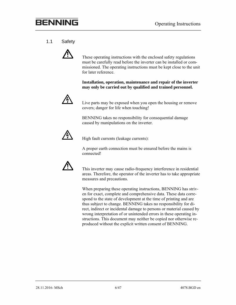
1.1 Safety
These operating instructions with the enclosed safety regulations must be carefully read before the inverter can be installed or com-missioned. The operating instructions must be kept close to the unit for later reference. Installation, operation, maintenance and repair of the inverter may only be carried out by qualified and trained personnel.
Live parts may be exposed when you open the housing or remove covers; danger for life when touching! BENNING takes no responsibility for consequential damage caused by manipulations on the inverter.
High fault currents (leakage currents): A proper earth connection must be ensured before the mains is connected!
This inverter may cause radio-frequency interference in residential areas. Therefore, the operator of the inverter has to take appropriate measures and precautions. When preparing these operating instructions, BENNING has striv-en for exact, complete and comprehensive data. These data corre-spond to the state of development at the time of printing and are thus subject to change. BENNING takes no responsibility for di-rect, indirect or incidental damage to persons or material caused by wrong interpretation of or unintended errors in these operating in-structions. This document may neither be copied nor otherwise re-produced without the explicit written consent of BENNING.
Operating Instructions
28.11.2016- MSch 7/47 4078.BGD en
2 Setting up and installation
2.1 Space requirement
The inverter INVERTRONIC can be set up with its rear to the wall. However, a clearance of 20 mm should be maintained.
In front of the unit, a clearance of approximately one meter must remain to en-sure unimpeded access and working on or in the unit.
In addition, local or even general safety regulations must be complied with (e.g. escape routes according to VDE 0100, Part 729).
A space of at least 60 cm should also be kept free above the inverter INVER-TRONIC to ensure that warm air can escape freely. Under no circumstances should the air inlet (in the door) and outlet (at the top) be obstructed or modi-fied.
2.2 Electrical installation
Terminal strips for the power connections (BY-PASS, load output) and copper-rail connections (battery) are provided in the bottom area of the cabinet of the inverter INVERTRONIC. The cables to the cabinet can be laid from all four sides and through the floor of the cabinet into the unit.
You must ensure that the phase sequence of the alternating current connections (clockwise rotating field) and the polarity of the bat-tery connection are correct, as any incorrect connections will cause damage to the unit.
Operating Instructions
28.11.2016- MSch 8/47 4078.BGD en
3 Commissioning
Prior to commissioning, always check the following:
1. Is the unit damaged? If so, consult BENNING before starting it up. 2. Has it been correctly wired (BY-PASS mains, output, battery, remote-control unit RCP etc.)? Correct if necessary.
3.1 Commissioning of the inverter unit INVERTRONIC
1. Check to ensure that all fuse switch-disconnectors, load-break switches and m.c.c.b. are open (off)!
2. Switch on the voltage for the BY-PASS and check the polarity and the ro-tating field at the input terminals if necessary.
3. Close (switch on) the m.c.c.b. Q401 (electronics AC supply) and Q400 (electronics DC supply).
4. Switch on the DC voltage supply (battery). Ensure correct polarity (+ and -).
5. Carry out a LED test by pressing the "Reset" key on the operating panel for a longer time.
6. The inverter unit is now ready for switching on. See chapter 4.3 for switching on and further handling.
Operating Instructions
28.11.2016- MSch 9/47 4078.BGD en
4 Operation
4.1 General
This section describes how to operate the inverter INVERTRONIC. First, the operating and display elements are described, followed by the procedures for commissioning and switching the system on and off. For smooth functioning of the system, it is essential that the individual steps are carried out in the order specified.
4.1.1 Operation
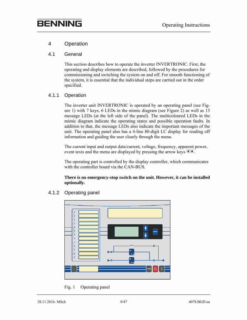
The inverter unit INVERTRONIC is operated by an operating panel (see Fig-ure 1) with 7 keys, 6 LEDs in the mimic diagram (see Figure 2) as well as 13 message LEDs (at the left side of the panel). The multicoloured LEDs in the mimic diagram indicate the operating states and possible operation faults. In addition to that, the message LEDs also indicate the important messages of the unit. The operating panel also has a 4-line 80-digit LC display for reading off information and guiding the user clearly through the menu.
The current input and output data/current, voltage, frequency, apparent power, event texts and the menu are displayed by pressing the arrow keys .
The operating part is controlled by the display controller, which communicates with the controller board via the CAN-BUS. There is no emergency-stop switch on the unit. However, it can be installed optionally.
4.1.2 Operating panel
Fig. 1 Operating panel
Operating Instructions
28.11.2016- MSch 10/47 4078.BGD en
4.2 Operating elements
Key "Arrow up" for scrolling back through the menu
Key "Arrow down" for scrolling forward through the menu
"RESET" key for confirming fault messages
O
"O" key for switching off
I
"I" key for switching on
BYPASS
"BY-PASS" key for switching on BY-PASS manually
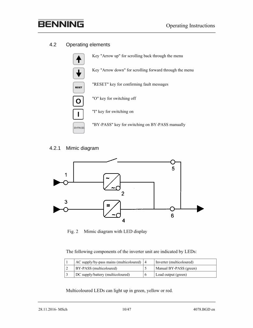
4.2.1 Mimic diagram
Fig. 2 Mimic diagram with LED display
The following components of the inverter unit are indicated by LEDs:
1 AC supply/by-pass mains (multicoloured) 4 Inverter (multicoloured)
2 BY-PASS (multicoloured) 5 Manual BY-PASS (green)
3 DC supply/battery (multicoloured) 6 Load output (green)
Multicoloured LEDs can light up in green, yellow or red.
Operating Instructions
28.11.2016- MSch 11/47 4078.BGD en
The colour and the lighting/flashing of the LEDs give information on the cur-rent operating state:
Green-yellow flashing Starting phase
Green flashing Precharge ok
Green glowing In operation i.e. switched on
Yellow flashing Warning
Yellow glowing Available i.e. ready for switch-on
Red flashing fault
Red glowing Abnormal state, e.g. mains error
4.2.2 LED messages
All in all, there are 13 message LEDs. The upper 9 are by default used as fol-lows:
1. power supply internal (green)
2. inverter operation (green)
3. by-pass operation (green)
4. parallel operation (green)
5. manual BY-PASS (green)
6. overload (yellow)
7. inverter fault (red)
8. mains fault (red)
9. battery low voltage (red)
The remaining 4 LEDs can be used customer-specifically.
Operating Instructions
28.11.2016- MSch 12/47 4078.BGD en
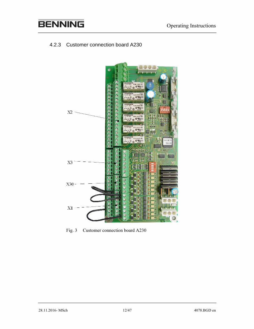
4.2.3 Customer connection board A230
Fig. 3 Customer connection board A230
Operating Instructions
28.11.2016- MSch 13/47 4078.BGD en
The terminals of the customer connection board (A230) are divided into four functions:
terminal strip X1, digital inputs
terminal strip X30, digital outputs
terminal strip X2, customer relay (potential-free messages)
terminal strip X3, analogue input and output
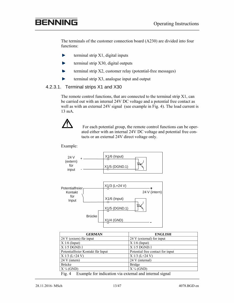
4.2.3.1. Terminal strips X1 and X30
The remote control functions, that are connected to the terminal strip X1, can be carried out with an internal 24V DC voltage and a potential free contact as well as with an external 24V signal (see example in Fig. 4). The load current is 13 mA.
For each potential group, the remote control functions can be oper-ated either with an internal 24V DC voltage and potential free con-tacts or an external 24V direct voltage only.
Example:
X1/6 (Input)
X1/6 (Input)
X1/5 (DGND.1)
+
-
X1/3 (L+24 V)
X1/5 (DGND.1)
X1/4 (GND)
24 V(extern)
für input
24 V (intern) Potentialfreier
Kontakt für
Input
Brücke
GERMAN ENGLISH 24 V (extern) für input 24 V (external) for input X 1/6 (Input) X 1/6 (Input) X 1/5 DGND.1 X 1/5 DGND.1 Potentialfreier Kontakt für Input Potential free contact for input X 1/3 (L+24 V) X 1/3 (L+24 V) 24 V (intern) 24 V (internal) Brücke Bridge X ¼ (GND) X ¼ (GND)
Fig. 4 Example for indication via external and internal signal
Operating Instructions
28.11.2016- MSch 14/47 4078.BGD en
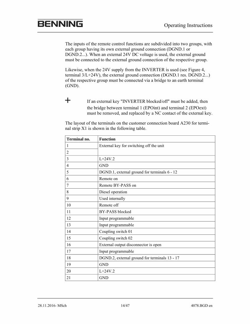
The inputs of the remote control functions are subdivided into two groups, with each group having its own external ground connection (DGND.1 or DGND.2...). When an external 24V DC voltage is used, the external ground must be connected to the external ground connection of the respective group.
Likewise, when the 24V supply from the INVERTER is used (see Figure 4, terminal 3/L+24V), the external ground connection (DGND.1 res. DGND.2...) of the respective group must be connected via a bridge to an earth terminal (GND).
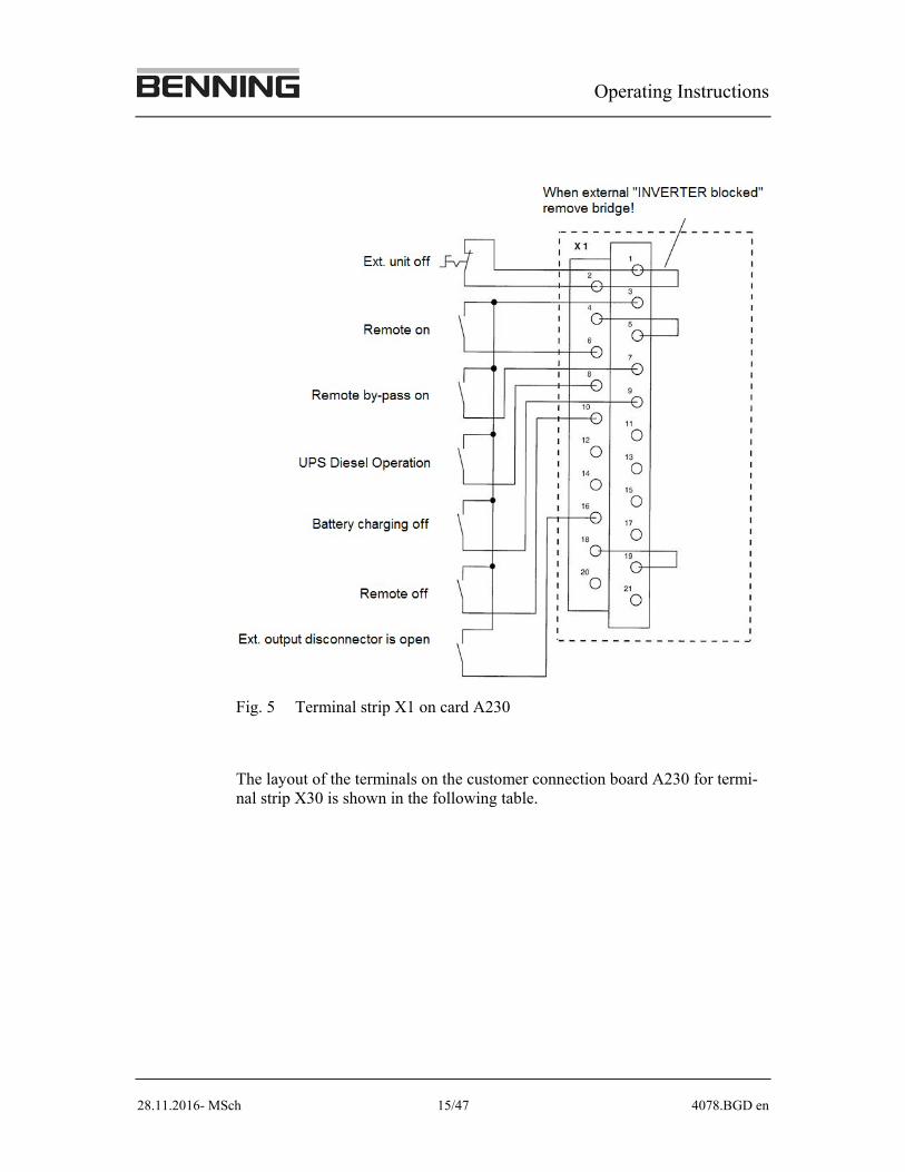
If an external key "INVERTER blocked/off" must be added, then
the bridge between terminal 1 (EPOint) and terminal 2 (EPOext) must be removed, and replaced by a NC contact of the external key.
The layout of the terminals on the customer connection board A230 for termi-nal strip X1 is shown in the following table.
Terminal no. Function
1 External key for switching off the unit
2
3 L+24V.2
4 GND
5 DGND.1, external ground for terminals 6 - 12
6 Remote on
7 Remote BY-PASS on
8 Diesel operation
9 Used internally
10 Remote off
11 BY-PASS blocked
12 Input programmable
13 Input programmable
14 Coupling switch 01
15 Coupling switch 02
16 External output disconnector is open
17 Input programmable
18 DGND.2, external ground for terminals 13 - 17
19 GND
20 L+24V.2
21 GND
Operating Instructions
28.11.2016- MSch 15/47 4078.BGD en
Fig. 5 Terminal strip X1 on card A230
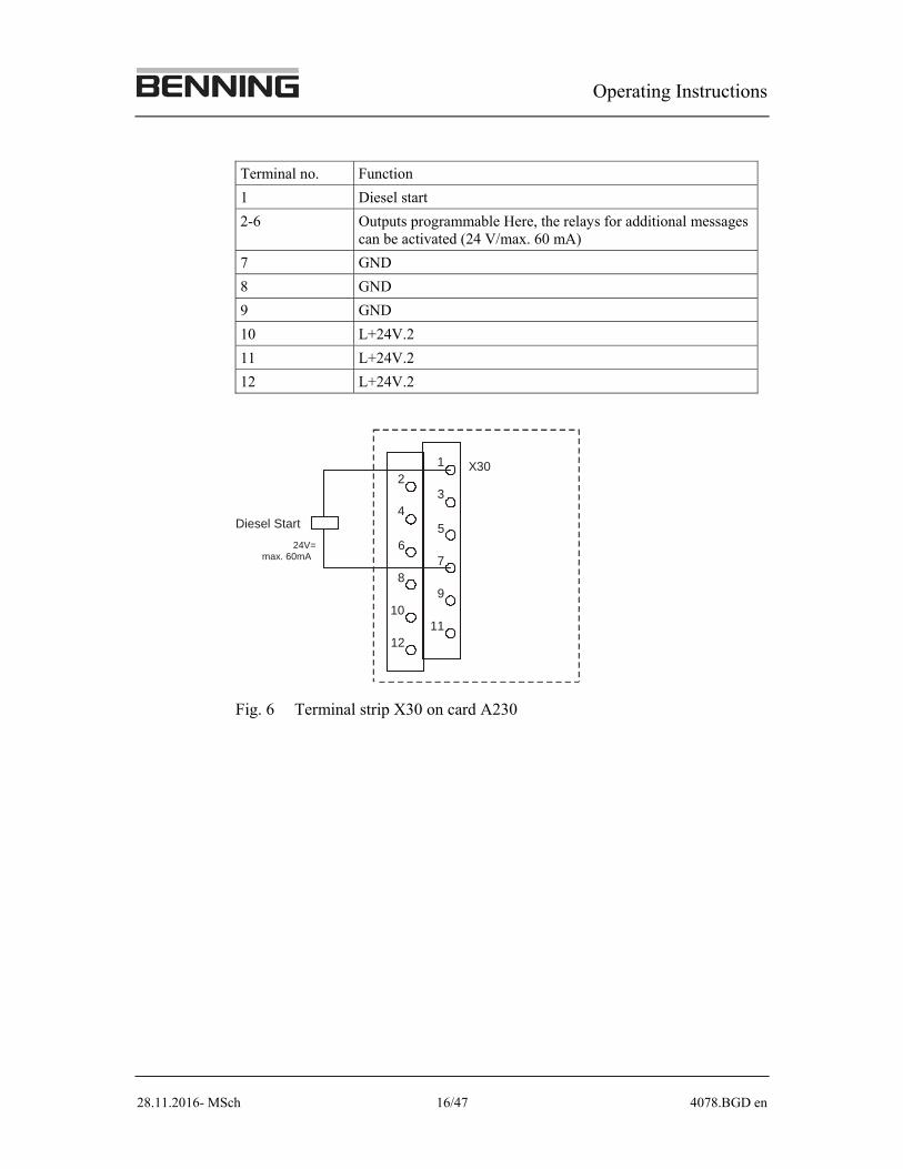
The layout of the terminals on the customer connection board A230 for termi-nal strip X30 is shown in the following table.
Operating Instructions
28.11.2016- MSch 16/47 4078.BGD en
Terminal no. Function
1 Diesel start
2-6 Outputs programmable Here, the relays for additional messages can be activated (24 V/max. 60 mA)
7 GND
8 GND
9 GND
10 L+24V.2
11 L+24V.2
12 L+24V.2
24V= max. 60mA
Diesel Start
1
3
5
7
9
11
X302
4
6
8
10
12
Fig. 6 Terminal strip X30 on card A230
Operating Instructions
28.11.2016- MSch 17/47 4078.BGD en
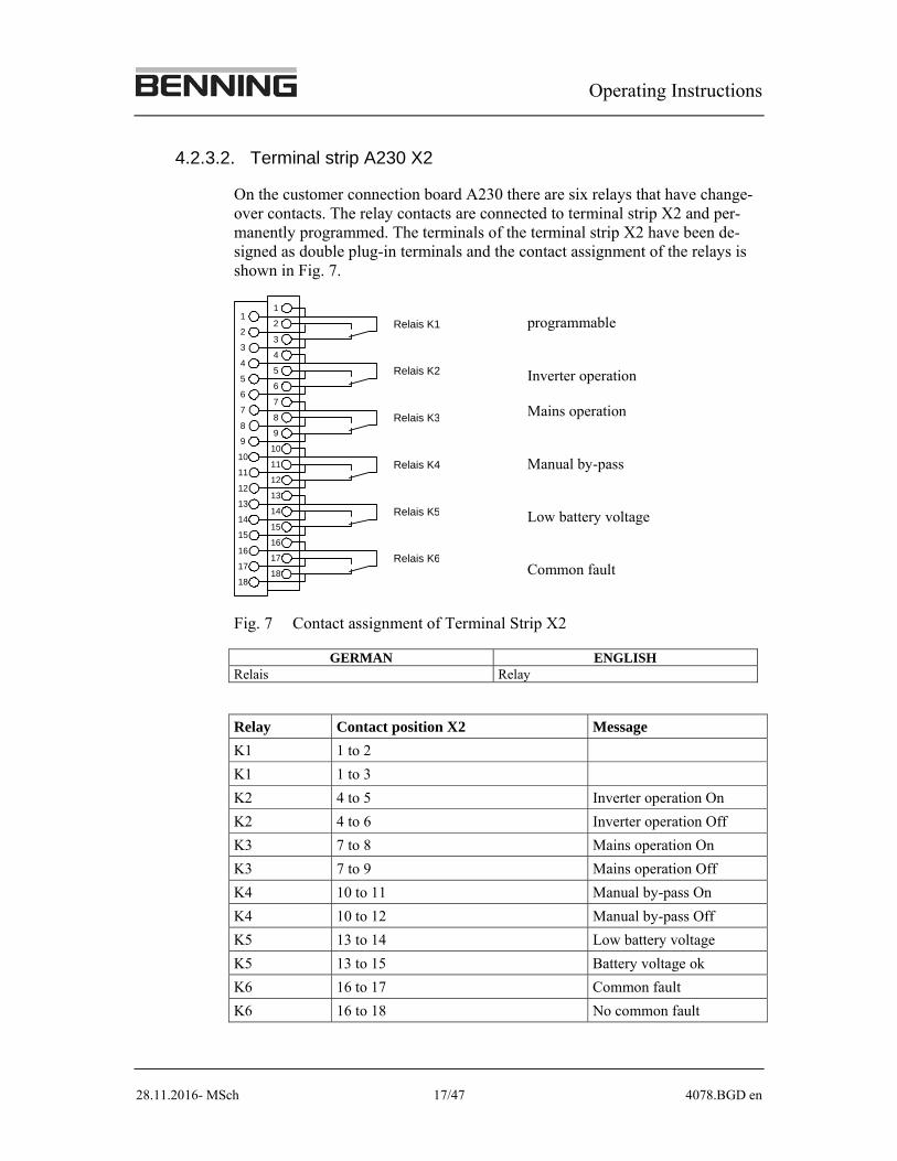
4.2.3.2. Terminal strip A230 X2
On the customer connection board A230 there are six relays that have change-over contacts. The relay contacts are connected to terminal strip X2 and per-manently programmed. The terminals of the terminal strip X2 have been de-signed as double plug-in terminals and the contact assignment of the relays is shown in Fig. 7.
Relais K1
Relais K2
Relais K3
Relais K4
Relais K5
Relais K6
1
2
3
4
5
6
7
8
9
10
11
12
13
14
15
16
17
18
1
2
3
4
5
6
7
8
9
10
11
12
13
14
15
16
17
18
programmable
Inverter operation
Mains operation
Manual by-pass
Low battery voltage
Common fault
Fig. 7 Contact assignment of Terminal Strip X2
GERMAN ENGLISH Relais Relay
Relay Contact position X2 Message
K1 1 to 2
K1 1 to 3
K2 4 to 5 Inverter operation On
K2 4 to 6 Inverter operation Off
K3 7 to 8 Mains operation On
K3 7 to 9 Mains operation Off
K4 10 to 11 Manual by-pass On
K4 10 to 12 Manual by-pass Off
K5 13 to 14 Low battery voltage
K5 13 to 15 Battery voltage ok
K6 16 to 17 Common fault
K6 16 to 18 No common fault
Operating Instructions
28.11.2016- MSch 18/47 4078.BGD en
Contact rating:
max. 250 V AC, 2 A
max. 300 V DC, 50 W
The contacts of the relays are thinly gold plated and thus also suita-
ble for small signal voltage applications.
If the relays are used once for switching power currents, e.g. a 230 V contactor, the thin gold plating evaporates, and subsequently they can no longer be used for small signal voltages.
Each relay is controlled by a logic function which is programmed with event numbers at the factory.
4.2.3.3. Customer connection board A231 (optional)
All digital and analogue inputs and outputs are programmable on customer connection board A231.
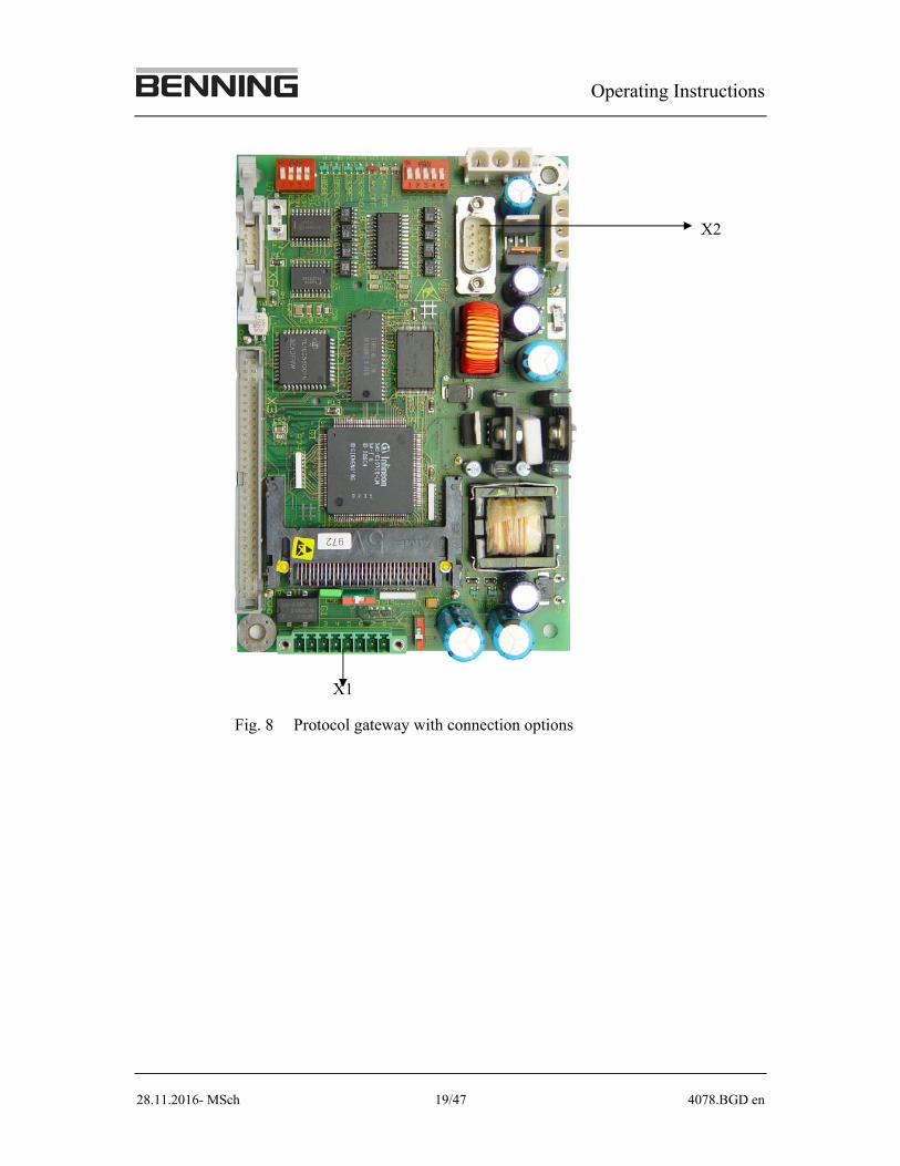
4.2.4 Protocol gateway
The protocol gateway is an interface for communication as well as for trans-mission of data protocols.
As connection options two interfaces are available on the protocol gateway which communicate via the MODBUS protocol.
These are a RS 232 interface and a RS 485 interface.
As standard, the unit is equipped with a protocol gateway card A250. The unit can optionally be equipped with an additional protocol gateway card.
Operating Instructions
28.11.2016- MSch 19/47 4078.BGD en
X2
X1
Fig. 8 Protocol gateway with connection options
Operating Instructions
28.11.2016- MSch 20/47 4078.BGD en
4.2.5 System control
The switch-on key I responds only to a short press whereas the switch-off key O responds only to a longer press (approx. 3 s). This shall prevent accidental
switch-off.
For safety reasons, important operations require confirmation. The enquiry by the system is confirmed by pressing the key a second time, following which the operation is carried out. If any key is pressed other than the one which initiated the enquiry, the operation is not carried out and the status of the unit remains unchanged. The status of the unit also remains unchanged if no response to the enquiry is received (i.e. no key is pressed) within 10 sec.
The desired action is only carried out when the key pressed is released.
4.2.6 Menus and display
The display of the operating panel shows the different operating states, faults as well as the different menus.
The corresponding operating state (by-pass operation, inverter operation etc.) is always shown after 2 minutes of normal operation. Exception: faults. The menus in the display are hierarchical menus. By pressing one of the both
/ keys, you enter the top menu level. The top menu level is arranged in
the same way as on a drum, i.e. if one of the / keys is pressed often enough, the same menu is reached again.
The current input and output data (such as current, voltage, power, phase dif-ference and frequency) can be taken from the top menu level.
You can enter a sub-menu such as an event and main menu by prolonged press-
ing of the key. The prolonged pressing of the key is signalled by two bleeps (unless the audible signal has been switched off).
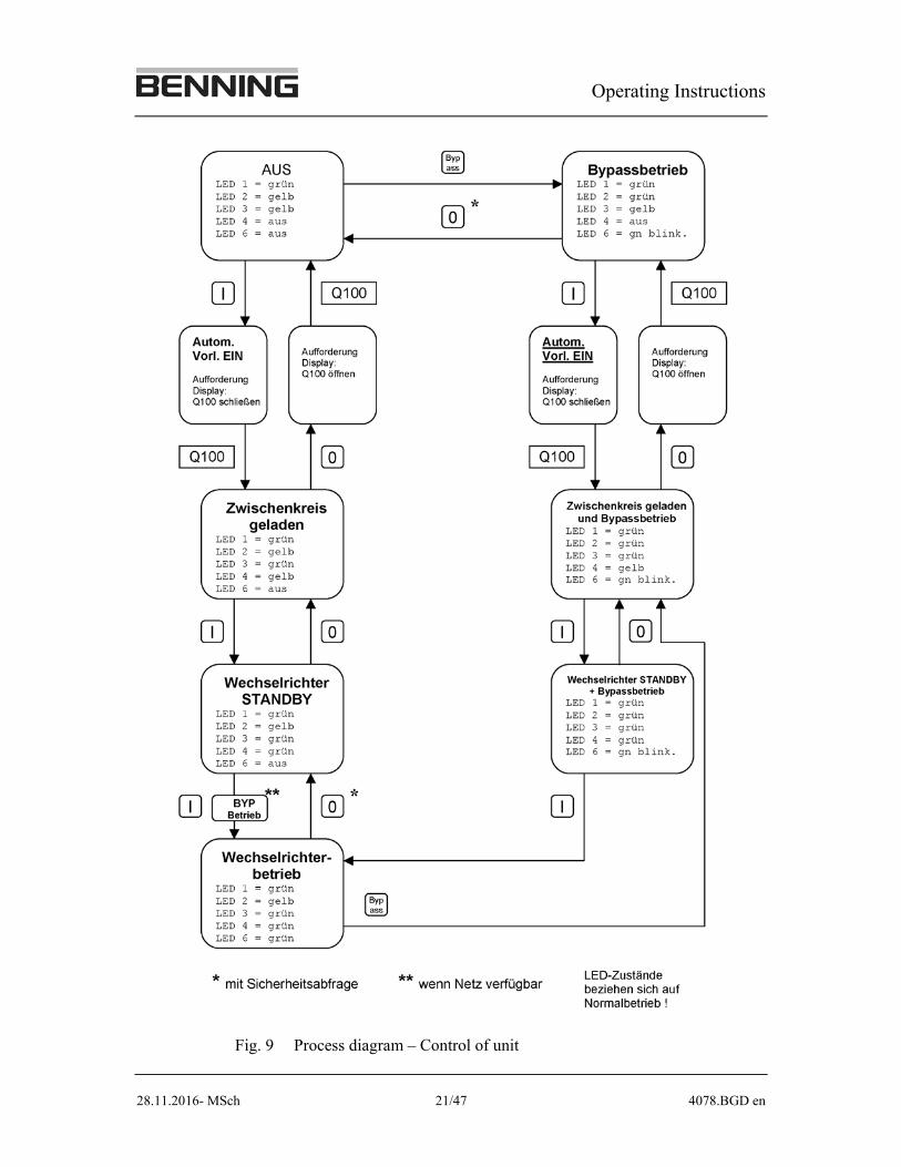
You can exit a sub-menu by prolonged pressing of the key. The menu structure for a one-phase unit is shown in figure 9. The only differences of the three-phase unit are situated in the menus "Inverter" and "BY-PASS".
Figure 9 shows at a glance how the different operating states can be achieved. The operating states (e.g. "off" or "inverter operation") are given in the large boxes. The arrows between the boxes indicate how to change from one operat-ing state to another. Just press the key beside the arrow.
Operating Instructions
28.11.2016- MSch 21/47 4078.BGD en
Fig. 9 Process diagram – Control of unit
Operating Instructions
28.11.2016- MSch 22/47 4078.BGD en
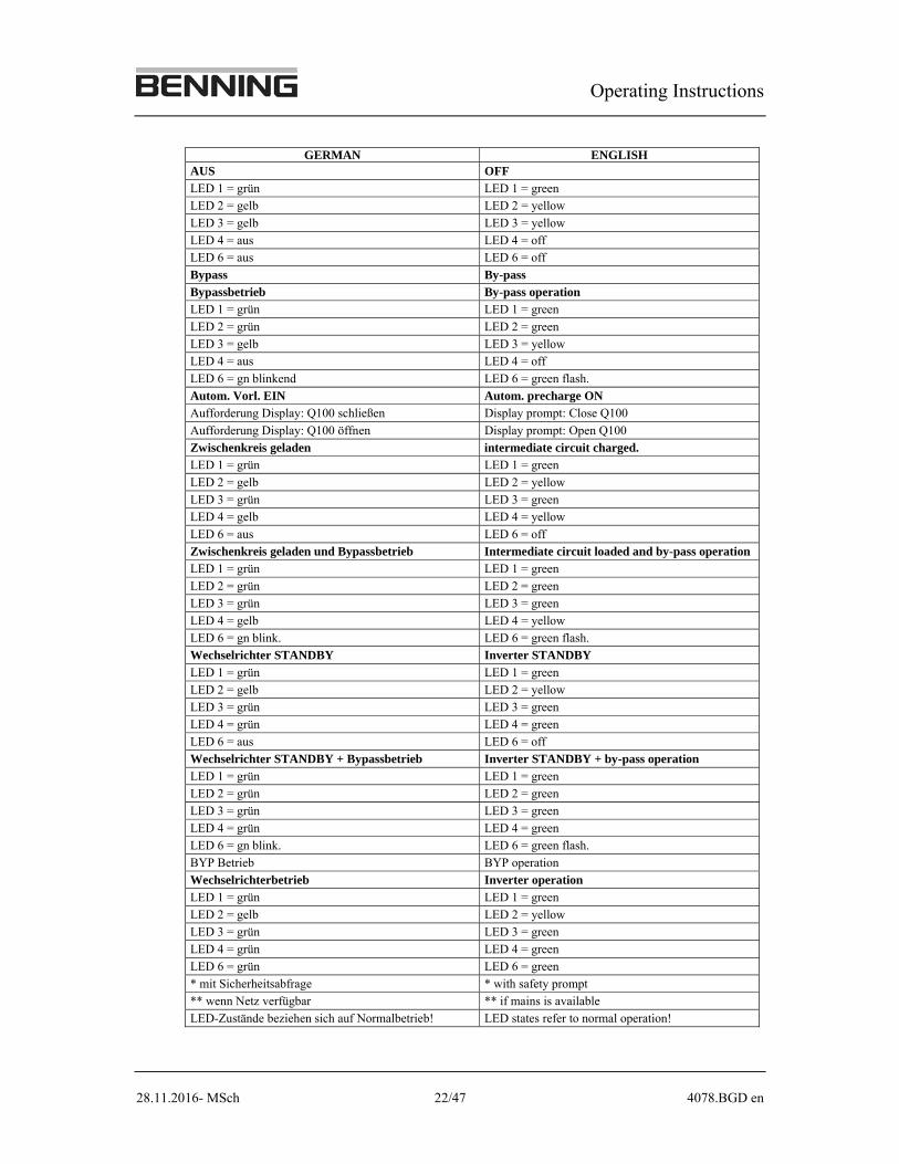
GERMAN ENGLISH AUS OFF
LED 1 = grün LED 1 = green LED 2 = gelb LED 2 = yellow
LED 3 = gelb LED 3 = yellow
LED 4 = aus LED 4 = off LED 6 = aus LED 6 = off
Bypass By-pass
Bypassbetrieb By-pass operation LED 1 = grün LED 1 = green
LED 2 = grün LED 2 = green
LED 3 = gelb LED 3 = yellow LED 4 = aus LED 4 = off
LED 6 = gn blinkend LED 6 = green flash.
Autom. Vorl. EIN Autom. precharge ON Aufforderung Display: Q100 schließen Display prompt: Close Q100
Aufforderung Display: Q100 öffnen Display prompt: Open Q100
Zwischenkreis geladen intermediate circuit charged. LED 1 = grün LED 1 = green
LED 2 = gelb LED 2 = yellow
LED 3 = grün LED 3 = green LED 4 = gelb LED 4 = yellow
LED 6 = aus LED 6 = off
Zwischenkreis geladen und Bypassbetrieb Intermediate circuit loaded and by-pass operation LED 1 = grün LED 1 = green
LED 2 = grün LED 2 = green
LED 3 = grün LED 3 = green
LED 4 = gelb LED 4 = yellow
LED 6 = gn blink. LED 6 = green flash.
Wechselrichter STANDBY Inverter STANDBY
LED 1 = grün LED 1 = green
LED 2 = gelb LED 2 = yellow
LED 3 = grün LED 3 = green
LED 4 = grün LED 4 = green
LED 6 = aus LED 6 = off
Wechselrichter STANDBY + Bypassbetrieb Inverter STANDBY + by-pass operation
LED 1 = grün LED 1 = green
LED 2 = grün LED 2 = green
LED 3 = grün LED 3 = green
LED 4 = grün LED 4 = green
LED 6 = gn blink. LED 6 = green flash.
BYP Betrieb BYP operation
Wechselrichterbetrieb Inverter operation
LED 1 = grün LED 1 = green
LED 2 = gelb LED 2 = yellow
LED 3 = grün LED 3 = green
LED 4 = grün LED 4 = green
LED 6 = grün LED 6 = green
* mit Sicherheitsabfrage * with safety prompt
** wenn Netz verfügbar ** if mains is available
LED-Zustände beziehen sich auf Normalbetrieb! LED states refer to normal operation!
Operating Instructions
28.11.2016- MSch 23/47 4078.BGD en
As a principle, the following has to be considered:
I key responds to short press. O key responds to longer press.
4.3 Working with the inverter unit INVERTRONIC
All the following switching operations are also shown in the process diagram (Figure 9).
4.3.1 Switching on
The fuse switch-disconnector must not be activated unless request-ed by the unit (see display), otherwise the inverter unit will be damaged.
1. Check if LED 1 (green) and LED 3 (yellow) glow continuously.
2. Press the key I on the operating panel. The charging process for the in-termediate circuit begins. During the precharge, LED 3 flashes green-yellow. When the preliminary charge voltage is achieved the green-yellow flashing turns into a green flashing.
LED 3 also lights green. To start the inverter, press key I again. During the starting process of the inverter, LED 4 flashes green-yellow. After the starting process, the unit is in the state "Inverter-STANDBY"; LED 4 is green.
3. Now press key I again. If the by-pass mains is available the BY-PASS is temporarily switched on. The unit passes into the state "Inverter opera-tion". The LEDs 3, 4 and 6 light up green and the inverter now takes on the secured supply of the load.
Operating Instructions
28.11.2016- MSch 24/47 4078.BGD en
4.3.2 Switching off with interruption of load supply
When the following action is carried out, the load is no longer sup-
plied.
Even when switched off, some of the components in the interior of the unit remain live. Only trained and qualified personnel should be allowed to work on the inverter unit. Even when the static switch is off, work on the output of the invert-er INVERTRONIC is prohibited. To do this, switch off the load-break switches Q51, Q52 and Q5 (three-phase unit) or F51, Q52 and Q5 (one-phase unit) to cut off the load.
1. Press key O longer. The following enquiry appears in the display for ap-prox. 10 sec.
Switch off inverter? Yes -> Press key again!
Confirm within 10 sec. by pressing key O again for a longer time. The output contactor is switched off. Status: "inverter-standby" If another key or no key is pressed during the 10 sec. the enquiry disap-pears from the display and the switch-off process is cancelled.
2. When key O is pressed again for a longer time, the inverter is switched off. Status: intermediate circuit charged.
3. When the key is pressed again for a longer time, the following instruction is displayed:
Open Q100!
When this instruction is carried out, the inverter is in the state "OFF".
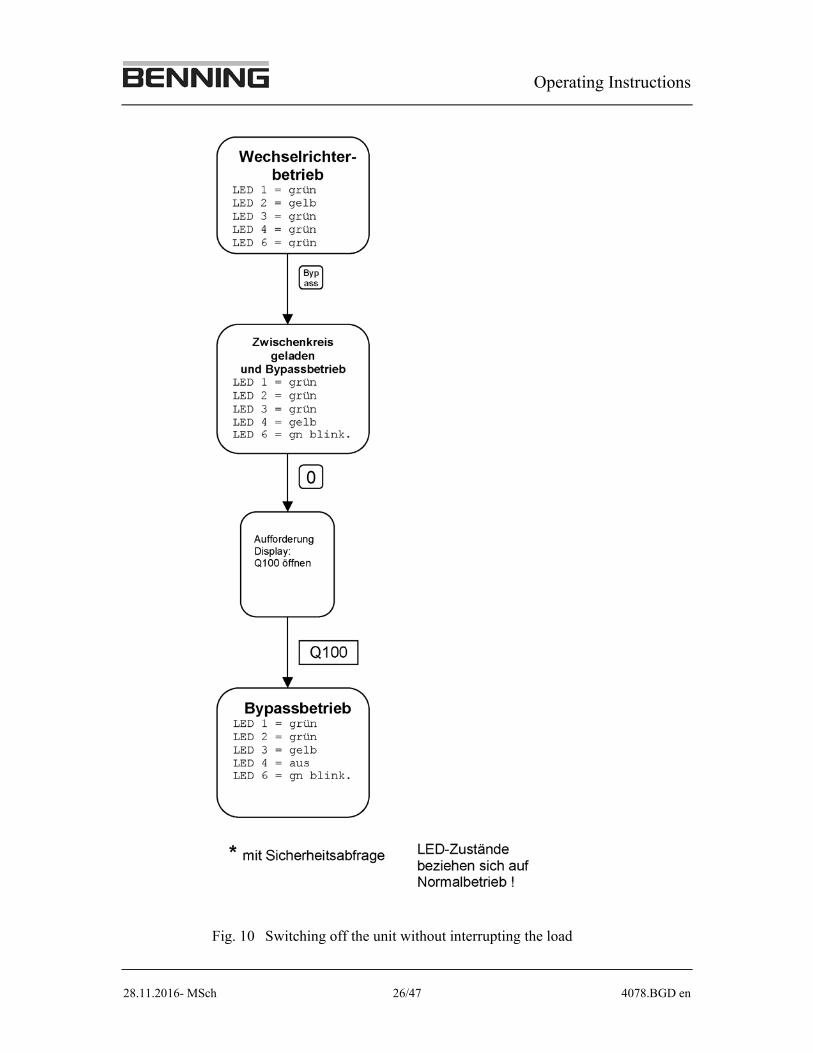
4.3.3 Switching off without interrupting the load supply
The following switching operations are also shown in the process diagram Fig-ure 10.
1. Check to ensure that the LED 1 is glowing green and LED 2 is glowing yellow. If this is not the case, there is a mains error and it is not possible to switch to BY-PASS.
Operating Instructions
28.11.2016- MSch 25/47 4078.BGD en
2. While in inverter operation, press the by-pass key BYPASS
. The load is now supplied via the by-pass net, inverter and output contactor are switched off. Status: Intermediate circuit loaded and by-pass operation.
3. Then press key O longer and open Q100 when requested to do so (see display).
In by-pass operation, LED 6 flashes green. LED 1 flashes green and LED 4 (inverter) is off.
Please note that the supply via the by-pass mains is no secured supply
of the load.
Operating Instructions
28.11.2016- MSch 26/47 4078.BGD en
Fig. 10 Switching off the unit without interrupting the load
Operating Instructions
28.11.2016- MSch 27/47 4078.BGD en
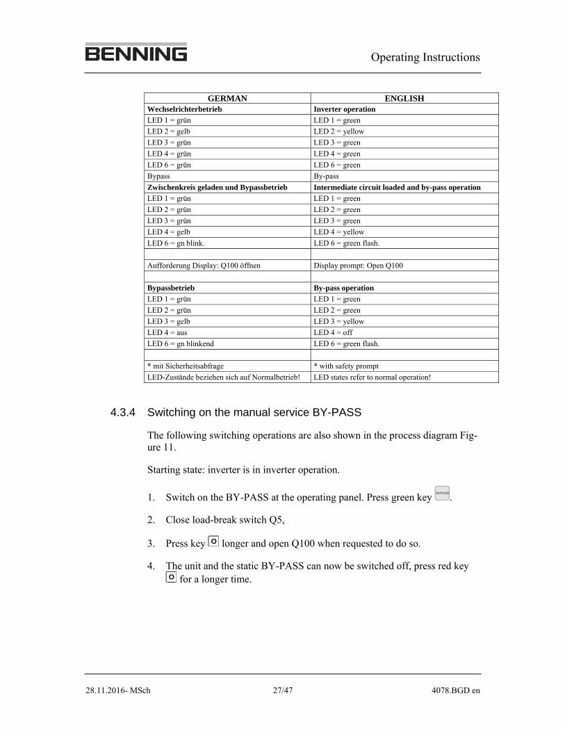
GERMAN ENGLISH Wechselrichterbetrieb Inverter operation
LED 1 = grün LED 1 = green
LED 2 = gelb LED 2 = yellow
LED 3 = grün LED 3 = green
LED 4 = grün LED 4 = green
LED 6 = grün LED 6 = green
Bypass By-pass
Zwischenkreis geladen und Bypassbetrieb Intermediate circuit loaded and by-pass operation
LED 1 = grün LED 1 = green
LED 2 = grün LED 2 = green
LED 3 = grün LED 3 = green
LED 4 = gelb LED 4 = yellow
LED 6 = gn blink. LED 6 = green flash.
Aufforderung Display: Q100 öffnen Display prompt: Open Q100
Bypassbetrieb By-pass operation
LED 1 = grün LED 1 = green
LED 2 = grün LED 2 = green
LED 3 = gelb LED 3 = yellow
LED 4 = aus LED 4 = off
LED 6 = gn blinkend LED 6 = green flash.
* mit Sicherheitsabfrage * with safety prompt
LED-Zustände beziehen sich auf Normalbetrieb! LED states refer to normal operation!
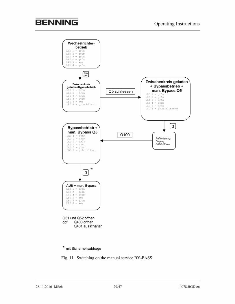
4.3.4 Switching on the manual service BY-PASS
The following switching operations are also shown in the process diagram Fig-ure 11.
Starting state: inverter is in inverter operation.
1. Switch on the BY-PASS at the operating panel. Press green key BYPASS
.
2. Close load-break switch Q5,
3. Press key O longer and open Q100 when requested to do so.
4. The unit and the static BY-PASS can now be switched off, press red key O for a longer time.
Operating Instructions
28.11.2016- MSch 28/47 4078.BGD en
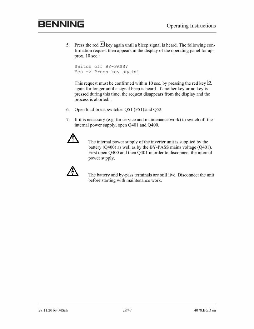
5. Press the red O key again until a bleep signal is heard. The following con-firmation request then appears in the display of the operating panel for ap-prox. 10 sec.: Switch off BY-PASS? Yes -> Press key again! This request must be confirmed within 10 sec. by pressing the red key O again for longer until a signal beep is heard. If another key or no key is pressed during this time, the request disappears from the display and the process is aborted. .
6. Open load-break switches Q51 (F51) and Q52.
7. If it is necessary (e.g. for service and maintenance work) to switch off the internal power supply, open Q401 and Q400.
The internal power supply of the inverter unit is supplied by the battery (Q400) as well as by the BY-PASS mains voltage (Q401). First open Q400 and then Q401 in order to disconnect the internal power supply.
The battery and by-pass terminals are still live. Disconnect the unit before starting with maintenance work.
Operating Instructions
28.11.2016- MSch 29/47 4078.BGD en
Fig. 11 Switching on the manual service BY-PASS
Operating Instructions
28.11.2016- MSch 30/47 4078.BGD en
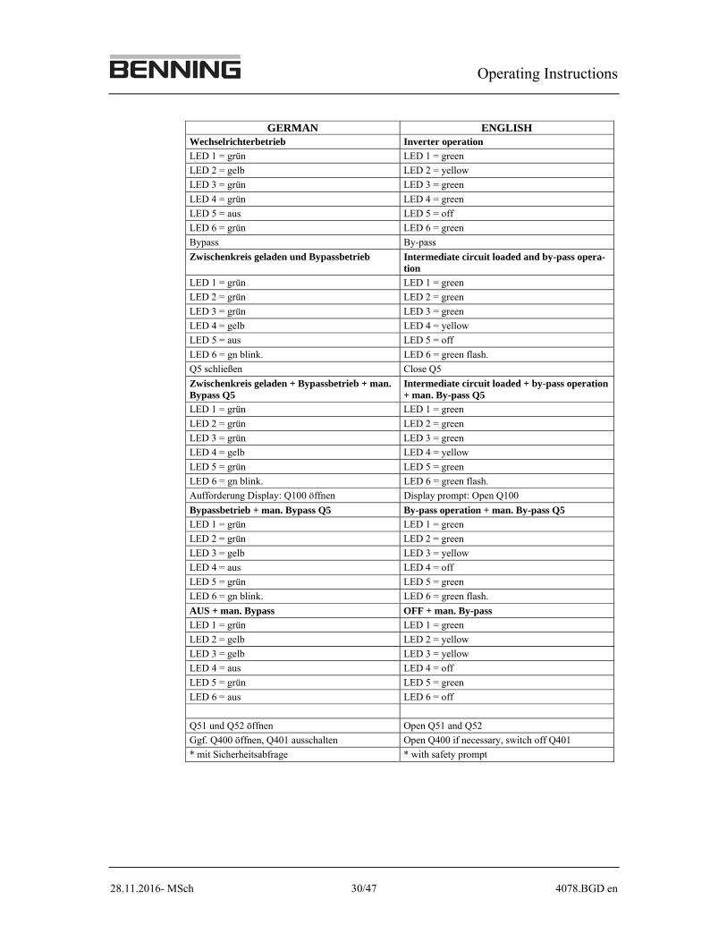
GERMAN ENGLISH Wechselrichterbetrieb Inverter operation
LED 1 = grün LED 1 = green
LED 2 = gelb LED 2 = yellow
LED 3 = grün LED 3 = green
LED 4 = grün LED 4 = green
LED 5 = aus LED 5 = off
LED 6 = grün LED 6 = green
Bypass By-pass
Zwischenkreis geladen und Bypassbetrieb Intermediate circuit loaded and by-pass opera-tion
LED 1 = grün LED 1 = green
LED 2 = grün LED 2 = green
LED 3 = grün LED 3 = green
LED 4 = gelb LED 4 = yellow
LED 5 = aus LED 5 = off
LED 6 = gn blink. LED 6 = green flash.
Q5 schließen Close Q5
Zwischenkreis geladen + Bypassbetrieb + man. Bypass Q5
Intermediate circuit loaded + by-pass operation + man. By-pass Q5
LED 1 = grün LED 1 = green
LED 2 = grün LED 2 = green
LED 3 = grün LED 3 = green
LED 4 = gelb LED 4 = yellow
LED 5 = grün LED 5 = green
LED 6 = gn blink. LED 6 = green flash.
Aufforderung Display: Q100 öffnen Display prompt: Open Q100
Bypassbetrieb + man. Bypass Q5 By-pass operation + man. By-pass Q5
LED 1 = grün LED 1 = green
LED 2 = grün LED 2 = green
LED 3 = gelb LED 3 = yellow
LED 4 = aus LED 4 = off
LED 5 = grün LED 5 = green
LED 6 = gn blink. LED 6 = green flash.
AUS + man. Bypass OFF + man. By-pass
LED 1 = grün LED 1 = green
LED 2 = gelb LED 2 = yellow
LED 3 = gelb LED 3 = yellow
LED 4 = aus LED 4 = off
LED 5 = grün LED 5 = green
LED 6 = aus LED 6 = off
Q51 und Q52 öffnen Open Q51 and Q52
Ggf. Q400 öffnen, Q401 ausschalten Open Q400 if necessary, switch off Q401
* mit Sicherheitsabfrage * with safety prompt
Operating Instructions
28.11.2016- MSch 31/47 4078.BGD en
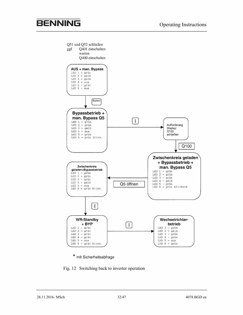
4.3.5 Switching back to inverter operation
If the internal power supply is switched off it must be switched on again at first.
1. Switch on all supply voltages (battery and by-pass net).
2. Close m.c.c.b. Q401. It takes approx. 20 sec. for the electronics to start up.
3. Close fuse switch-disconnector Q400.
4. Close load-break switches Q51 (F51) and Q52.
5. Switch on the static BY-PASS by means of the green key BYPASS
on the oper-ating panel.
6. Open load-break switch Q5.
7. Switching on again the inverter unit as described in the process diagram in Figure 12.
4.3.6 DC power supply failure
In the event of DC power supply failure, Q100 must be opened immediately and the inverter system restarted as described in Chapter 4.3.1.
Operating Instructions
28.11.2016- MSch 32/47 4078.BGD en
Fig. 12 Switching back to inverter operation
Operating Instructions
28.11.2016- MSch 33/47 4078.BGD en
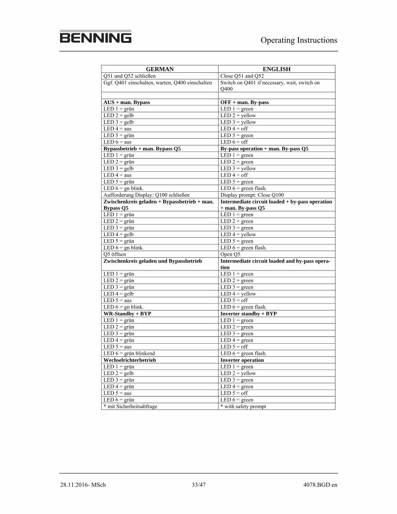
GERMAN ENGLISH Q51 und Q52 schließen Close Q51 and Q52 Ggf. Q401 einschalten, warten, Q400 einschalten Switch on Q401 if necessary, wait, switch on
Q400 AUS + man. Bypass OFF + man. By-pass LED 1 = grün LED 1 = green LED 2 = gelb LED 2 = yellow LED 3 = gelb LED 3 = yellow LED 4 = aus LED 4 = off LED 5 = grün LED 5 = greenLED 6 = aus LED 6 = off Bypassbetrieb + man. Bypass Q5 By-pass operation + man. By-pass Q5 LED 1 = grün LED 1 = green LED 2 = grün LED 2 = green LED 3 = gelb LED 3 = yellow LED 4 = aus LED 4 = off LED 5 = grün LED 5 = greenLED 6 = gn blink. LED 6 = green flash. Aufforderung Display: Q100 schließen Display prompt: Close Q100 Zwischenkreis geladen + Bypassbetrieb + man. Bypass Q5
Intermediate circuit loaded + by-pass operation + man. By-pass Q5
LED 1 = grün LED 1 = green LED 2 = grün LED 2 = green LED 3 = grün LED 3 = green LED 4 = gelb LED 4 = yellowLED 5 = grün LED 5 = green LED 6 = gn blink. LED 6 = green flash. Q5 öffnen Open Q5 Zwischenkreis geladen und Bypassbetrieb Intermediate circuit loaded and by-pass opera-
tion LED 1 = grün LED 1 = green LED 2 = grün LED 2 = green LED 3 = grün LED 3 = green LED 4 = gelb LED 4 = yellow LED 5 = aus LED 5 = off LED 6 = gn blink. LED 6 = green flash. WR-Standby + BYP Inverter standby + BYPLED 1 = grün LED 1 = green LED 2 = grün LED 2 = green LED 3 = grün LED 3 = greenLED 4 = grün LED 4 = green LED 5 = aus LED 5 = off LED 6 = grün blinkend LED 6 = green flash. Wechselrichterbetrieb Inverter operationLED 1 = grün LED 1 = green LED 2 = gelb LED 2 = yellow LED 3 = grün LED 3 = green LED 4 = grün LED 4 = green LED 5 = aus LED 5 = off LED 6 = grün LED 6 = green* mit Sicherheitsabfrage * with safety prompt
Operating Instructions
28.11.2016- MSch 34/47 4078.BGD en
4.4 Parallel operation of inverters
4.4.1 General
A maximum of 8 inverter units can be switched parallel to one another via a CAN-BUS. For this purpose, each of the inverters has to be equipped for paral-lel operation.
The two following parallel modes can be selected. They are set using the oper-ating panel (see section 4.5.11 "Key lock"). The settings must be made when the unit is switched off or in by-pass operation
Power parallel:
Increased power. In this operation mode, the failure of an inverter causes all the inverters in par-allel operation to switch immediately to by-pass operation.
Redundant parallel:
Increased reliability. In this operation mode, at least one unit more is used than is required to cover the power requirement. The control system distinguishes between "Redundan-cy = 1", "Redundancy = 2", "Redundancy = 3", and "Redundancy = 4".
"Redundancy = 1" means that the BY-PASS is not triggered until two units fail.
"Redundancy = 2" (or 3 or 4) can only be selected when at least three (or four or five) units are in parallel operation and means that the BY-PASS is only switched on when more than two (or three or four) units fail. The manufacturer's setting is "Redundancy = 1". If you wish a change in the setting, please consult us.
4.4.2 Load distribution
A special control system in each unit ensures an even distribution of load cur-rent. All the units operate in synchronisation with the current supply as long as the by-pass mains is within the frequency tolerance. Outside the tolerance, the units are self-controlled and are synchronised according to the signal from the synchronisation master.
Each inverter in parallel operation can switch the synchronisation signal to the parallel bus.
Operating Instructions
28.11.2016- MSch 35/47 4078.BGD en
4.4.3 Operation of the parallel group
4.4.3.1. Starting of a parallel group
A parallel group of INVERTRONIC inverters is always switched on via the BY-PASS. It is of no importance whether they are power or redundant parallel units. In the case of parallel units, switching on without BY-PASS is prevented by the software. Always switch the BY-PASS on first.
1. Press key BYPASS
briefly (press BYPASS
key briefly once on one unit).
2. Switch each inverter to "Inverter STANDBY" in accordance with process diagram (Figure 9).
3. Switch on the output contactors of the units one after another. Press key ( I on each unit once briefly).
The parallel systems differ as follows:
Power parallel: The units which are switched on and which have closed the output contac-tor K6 operate parallel to the by-pass until the last unit of the group has switched on its output contactor. All the units in the group do not switch the BY-PASS off until this has taken place.
Redundant parallel: The units which are switched on and which have closed the output contac-tor K6 operate parallel to the by-pass until the redundancy condition is ful-filled. All the units in the group then switch the BY-PASS off. Each re-maining unit in the redundancy group which has not yet closed the output contactor, can now be switched on. However, they do not switch the BY-PASS on if the output contactor is closed, as this would cause the entire group to switch the BY-PASS on again.
4.4.3.2. Switching off the whole parallel group
An INVERTRONIC parallel group is always switched off via the BY-PASS. It is of no importance whether they are power or redun-dant parallel inverters. Always switch the BY-PASS on first.
1. BYPASS
Press key once briefly (press BYPASS
key briefly on one unit).
2. Switch all units off (press O key once on each unit for a longer time and activate).
Operating Instructions
28.11.2016- MSch 36/47 4078.BGD en
3. Open Q100 on all units.
4. Switch off all by-passes (press O key on each unit twice for a longer time, safety confirmation request required).
5. Completely disconnect the unit as necessary, when the unit will not be used for a longer period of time.
During operation, do not pull out any parallel cables!
4.4.3.3. Switching off an inverter from a redundant parallel group
As long as the redundancy condition is not infringed, one or more inverters can be taken out of the parallel group.
To take out an inverter from a redundant group, follow the left path of the pro-cess diagram in Figure 9 from the state "Inverter operation" to the state "OFF".
4.4.3.4. Switching on an inverter in a redundant parallel group
To switch on again an inverter in a redundant group, follow the left path of the process diagram in Figure 9 from the state "OFF" to the state "Inverter opera-tion".
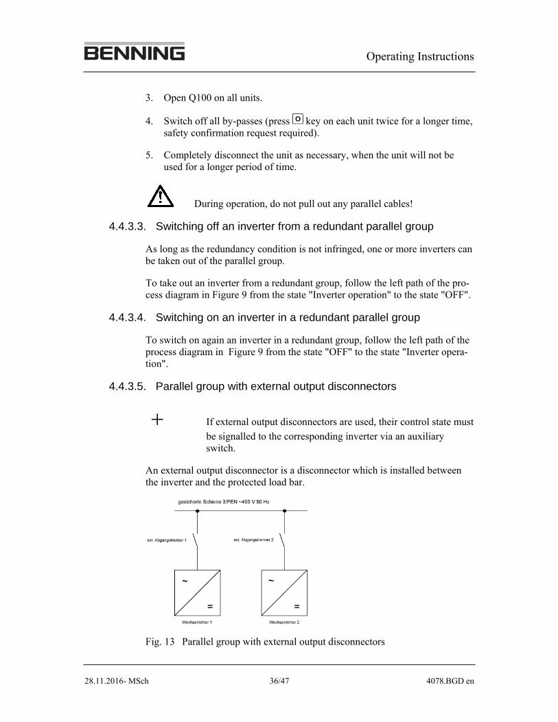
4.4.3.5. Parallel group with external output disconnectors
If external output disconnectors are used, their control state must
be signalled to the corresponding inverter via an auxiliary switch.
An external output disconnector is a disconnector which is installed between the inverter and the protected load bar.
Fig. 13 Parallel group with external output disconnectors
Operating Instructions
28.11.2016- MSch 37/47 4078.BGD en
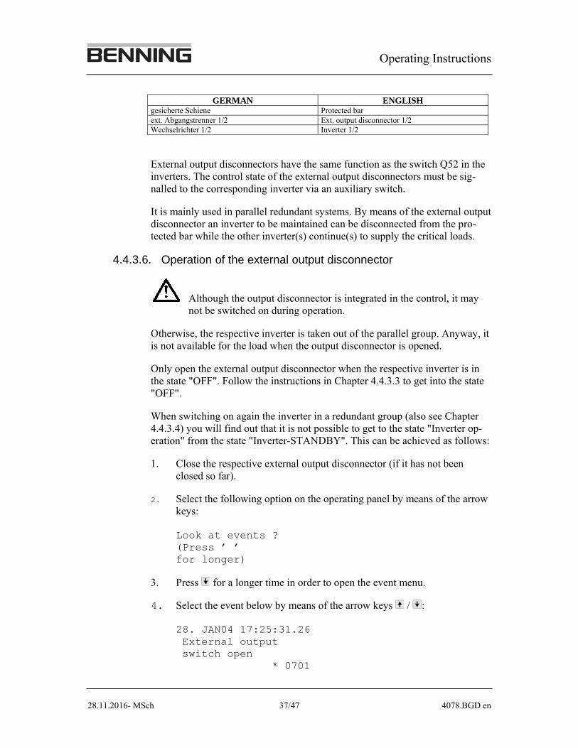
GERMAN ENGLISH gesicherte Schiene Protected bar ext. Abgangstrenner 1/2 Ext. output disconnector 1/2 Wechselrichter 1/2 Inverter 1/2
External output disconnectors have the same function as the switch Q52 in the inverters. The control state of the external output disconnectors must be sig-nalled to the corresponding inverter via an auxiliary switch.
It is mainly used in parallel redundant systems. By means of the external output disconnector an inverter to be maintained can be disconnected from the pro-tected bar while the other inverter(s) continue(s) to supply the critical loads.
4.4.3.6. Operation of the external output disconnector
Although the output disconnector is integrated in the control, it may not be switched on during operation.
Otherwise, the respective inverter is taken out of the parallel group. Anyway, it is not available for the load when the output disconnector is opened.
Only open the external output disconnector when the respective inverter is in the state "OFF". Follow the instructions in Chapter 4.4.3.3 to get into the state "OFF".
When switching on again the inverter in a redundant group (also see Chapter 4.4.3.4) you will find out that it is not possible to get to the state "Inverter op-eration" from the state "Inverter-STANDBY". This can be achieved as follows:
1. Close the respective external output disconnector (if it has not been closed so far).
2. Select the following option on the operating panel by means of the arrow keys: Look at events ? (Press ’�’ for longer)
3. Press for a longer time in order to open the event menu.
4. Select the event below by means of the arrow keys / : 28. JAN04 17:25:31.26 External output switch open * 0701
Operating Instructions
28.11.2016- MSch 38/47 4078.BGD en
5. Confirm the event by means of the key . 28. JAN04 17:25:31.26 External output switch open R 0701
6. The inverter now goes into the state "Inverter operation" (otherwise, again press the key I ).
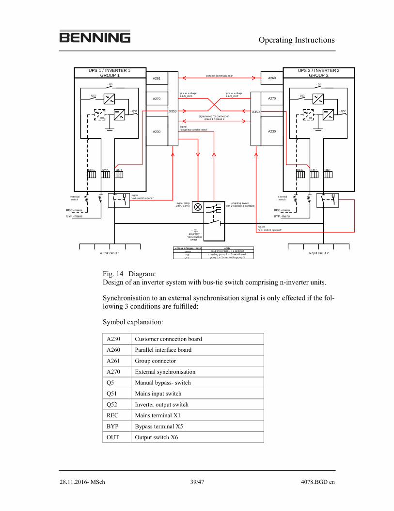
4.4.3.7. External Synchronisation
External synchronisation is required if an inverter systems comprising n- in-verter units (n=8) that is connected in parallel should be split into two out-going bars 1 and 2 each, by means of an external bus-tie switch in two autono-mous inverter systems comprising m- inverter units (m≥1). The number of in-verter units in the newly built inverter groups can vary. The parallel bus is split by means of the group connector in the inverter unit 1. This split-up produces two completely autonomous new inverter systems which are each switched into two differing inverter groups by the group connector. Due to this split-up the inverter systems can also run differing parallel operation protocols.
A new parallel operation protocol must be programmed for each group.
It is the function of the external synchronisation to synchronise the output of the inverter system to the external synchronisation signal so that the inverter output and the external synchronisation signal are always phase and frequency synchronised. Synchronisation is always active if the bus-tie switch is open and the BY-PASS of the inverter unit is not available. Each inverter system must be equipped with its own synchronisation card! This card is always installed in the inverter unit with the highest unit number of the inverter system.
The bus-tie switch Q1 is provided with an H1 LED. It should be mounted in the immediate vicinity of the bus-tie switch. If the LED is green, the inverter outputs are synchronised and the bus-tie switch can be closed. If the LED is red, the bus-tie switch must not be switched!
A non-illuminated LED indicates that the bus-tie switch is closed and the out-put bars are interconnected.
If 2 coupling switches are available the auxiliary contacts have to be wired in series.
Operating Instructions
28.11.2016- MSch 39/47 4078.BGD en
phase v oltage L1-N_BYP.
phase v oltageL1-N_OUT
signal wires for connect iongroup 1 / group 2
signal "ext. switch opend"
externalswitch
externalswitch
- Q5
- Q51
- Q52- Q52
- Q51
- Q5
output circuit 2output circuit 1
UPS 1 / INVERTER 1 GROUP 1
UPS 2 / INVERTER 2GROUP 2
OUTBYP.REC. BYP. OUT
colour of signal lamp
- Q1assem bly
"led coupling switch"
signal lamp24V / 18m A
coupling switchwith 2 signalling contac ts
REC.
A230
A270
A260
X350X350
A270
A230
A261
group 1 + 2 coupled i n group 3coupling group 1 + 2 not allowed
coupling group 1 + 2 allowed
REC.-mains
BYP.-mainsBYP.-mains
REC.-mains
parallel communication
signal"coupling switch c losed"
signal"ext. switch opened"
OFF
greenstate
red
Fig. 14 Diagram: Design of an inverter system with bus-tie switch comprising n-inverter units.
Synchronisation to an external synchronisation signal is only effected if the fol-lowing 3 conditions are fulfilled:
Symbol explanation:
A230 Customer connection board
A260 Parallel interface board
A261 Group connector
A270 External synchronisation
Q5 Manual bypass- switch
Q51 Mains input switch
Q52 Inverter output switch
REC Mains terminal X1
BYP Bypass terminal X5
OUT Output switch X6
Operating Instructions
28.11.2016- MSch 40/47 4078.BGD en
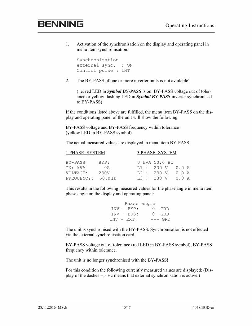
1. Activation of the synchronisation on the display and operating panel in menu item synchronisation: Synchronisation external sync. : ON Control pulse : INT
2. The BY-PASS of one or more inverter units is not available! (i.e. red LED in Symbol BY-PASS is on: BY-PASS voltage out of toler-ance or yellow flashing LED in Symbol BY-PASS inverter synchronised to BY-PASS)
If the conditions listed above are fulfilled, the menu item BY-PASS on the dis-play and operating panel of the unit will show the following:
BY-PASS voltage and BY-PASS frequency within tolerance (yellow LED in BY-PASS symbol).
The actual measured values are displayed in menu item BY-PASS.
1 PHASE- SYSTEM 3 PHASE- SYSTEM
BY-PASS BYP: 0 kVA 50.0 Hz IN: kVA 0A L1 : 230 V 0.0 A VOLTAGE: 230V L2 : 230 V 0.0 A FREQUENCY: 50.0Hz L3 : 230 V 0.0 A
This results in the following measured values for the phase angle in menu item phase angle on the display and operating panel:
Phase angle INV – BYP: 0 GRD INV – BUS: 0 GRD INV – EXT: --- GRD
The unit is synchronised with the BY-PASS. Synchronisation is not effected via the external synchronisation card.
BY-PASS voltage out of tolerance (red LED in BY-PASS symbol), BY-PASS frequency within tolerance.
The unit is no longer synchronised with the BY-PASS!
For this condition the following currently measured values are displayed: (Dis-play of the dashes --,- Hz means that external synchronisation is active.)
Operating Instructions
28.11.2016- MSch 41/47 4078.BGD en
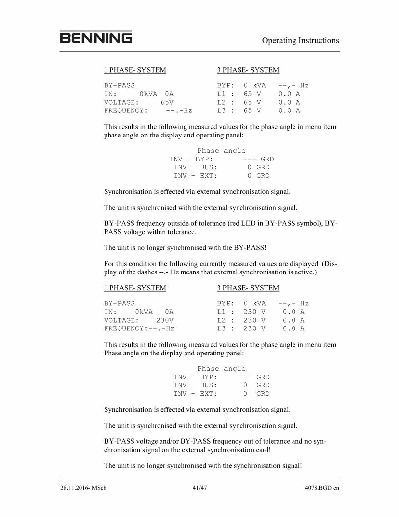
1 PHASE- SYSTEM 3 PHASE- SYSTEM
BY-PASS BYP: 0 kVA --,- Hz IN: 0kVA 0A L1 : 65 V 0.0 A VOLTAGE: 65V L2 : 65 V 0.0 A FREQUENCY: --.-Hz L3 : 65 V 0.0 A
This results in the following measured values for the phase angle in menu item phase angle on the display and operating panel:
Phase angle INV – BYP: --- GRD INV – BUS: 0 GRD INV – EXT: 0 GRD
Synchronisation is effected via external synchronisation signal.
The unit is synchronised with the external synchronisation signal.
BY-PASS frequency outside of tolerance (red LED in BY-PASS symbol), BY-PASS voltage within tolerance.
The unit is no longer synchronised with the BY-PASS!
For this condition the following currently measured values are displayed: (Dis-play of the dashes --,- Hz means that external synchronisation is active.)
1 PHASE- SYSTEM 3 PHASE- SYSTEM
BY-PASS BYP: 0 kVA --,- Hz IN: 0kVA 0A L1 : 230 V 0.0 A VOLTAGE: 230V L2 : 230 V 0.0 A FREQUENCY:--.-Hz L3 : 230 V 0.0 A
This results in the following measured values for the phase angle in menu item Phase angle on the display and operating panel:
Phase angle INV – BYP: --- GRD INV – BUS: 0 GRD INV – EXT: 0 GRD
Synchronisation is effected via external synchronisation signal.
The unit is synchronised with the external synchronisation signal.
BY-PASS voltage and/or BY-PASS frequency out of tolerance and no syn-chronisation signal on the external synchronisation card!
The unit is no longer synchronised with the synchronisation signal!
Operating Instructions
28.11.2016- MSch 42/47 4078.BGD en
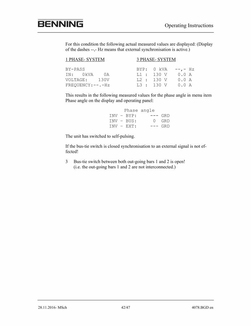
For this condition the following actual measured values are displayed: (Display of the dashes --,- Hz means that external synchronisation is active.)
1 PHASE- SYSTEM 3 PHASE- SYSTEM
BY-PASS BYP: 0 kVA --,- Hz IN: 0kVA 0A L1 : 130 V 0.0 A VOLTAGE: 130V L2 : 130 V 0.0 A FREQUENCY:--.-Hz L3 : 130 V 0.0 A
This results in the following measured values for the phase angle in menu item Phase angle on the display and operating panel:
Phase angle INV – BYP: --- GRD INV – BUS: 0 GRD INV – EXT: --- GRD
The unit has switched to self-pulsing.
If the bus-tie switch is closed synchronisation to an external signal is not ef-fected!
3 Bus-tie switch between both out-going bars 1 and 2 is open! (i.e. the out-going bars 1 and 2 are not interconnected.)
Operating Instructions
28.11.2016- MSch 43/47 4078.BGD en
4.5 Settings
In the display of the inverter INVERTRONIC, a number of menus are availa-ble which allow the user to make his own specific settings. The setting menu is accessed by means of the arrow keys . By pressing the arrow key for longer, the sub-menus can be accessed. To scroll through the sub-menus and make the desired settings, press the arrow keys
The individual sub-menus and possible settings are described in succession be-low.
4.5.1 Language
Set the language for the display.
4.5.2 Date/time
Set the current date and time if required and specify that the changed values should be accepted by the system.
4.5.3 Printing
With this menu, you can print out the log of events in the memory and the in-verter state (if a printer is connected).
4.5.4 Set-up
This menu is required at the end of the settings for programming the settings in EEPROM.
At the end of the setting process, return to this menu to program the settings in-to the EEPROM.
Save new data: Enter "Yes" if you want to save the settings.
Use old data: Enter "Yes" if you want to delete the new settings and return to the data last stored.
4.5.5 Auto start
When you enter "ON", the inverter is started automatically after a battery low voltage as soon as the battery is again loaded by the rectifiers (battery voltage >2 V / cell of lead accumulator batteries, battery voltage > 1.2 V / cell of NiCd batteries).
If "Autostart" is switched on, persons working in the unit during the mains failure may be in danger.
Operating Instructions
28.11.2016- MSch 44/47 4078.BGD en
4.5.6 Contrast
This menu enables you to change the display contrast.
4.5.7 Output voltage
The desired output voltage can be set within the range 5 %.
4.5.8 Password
A password is needed to make settings in some of the menus. Please consult the manufacturer.
4.5.9 Software versions
For service purposes, the programmed software versions can be called up.
4.5.10 Type
The unit-type designation displayed is set by the manufacturer.
4.5.11 Key lock (password protection)
Here you can state whether a password is required for all switching operations at the operating panel of the inverter INVERTRONIC. If so, enter "Yes".
4.5.12 Parallel operation
For parallel units, in this menu parallel operation must always be
set to "ON". For single units: Parallel operation "OFF".
Operating Instructions
28.11.2016- MSch 45/47 4078.BGD en
Selection of parallel-power mode: For parallel-power mode, the mode must be set to "Parallel power". For correct operation in parallel-power mode, the minimum number of units required in this parallel group must be set in the next line. In this operation mode, that is the total number of units in parallel-power oper-ation. E.g. 3 units -> a minimum of 3 units are required. The setting is then stored with the SETUP menu item or with "prog all". After storing the setting, all the units of the group making up the CAN-BUS should have accepted the settings. However, the acceptance of the settings by all the units should be checked and if necessary corrected. The group is now set up for parallel-power mode.
Selection of parallel-redundant mode: For parallel-redundant mode, the operation mode must be set to "Re-dundant parallel". For correct operation in parallel-redundant mode, the minimum number of units required in this parallel group must be set in the next line. E.g.: 3 units, of which 1 unit redundant -> at least 2 units are required. The setting is then stored with the SETUP menu item or with "prog all". After storing the setting, all the units of the group making up the CAN-BUS should have accepted the settings. However, the acceptance of the settings by all the units should be checked and if necessary corrected. The group is now set up for the desired parallel-redundant operation.
4.5.13 Block BY-PASS
Block BY-PASS in diesel operation: Here you can specify whether the BY-PASS should be lock for diesel operation.
Block BY-PASS in mains operation: You can determine if the BY-PASS of the inverter is to be locked in case of mains operation.
Operating Instructions
28.11.2016- MSch 46/47 4078.BGD en
5 Trouble shooting
Every type of error or malfunction in the system is shown in the display.
Should an error or malfunction occur, proceed as follows:
To delete the fault message in the display, press the "Reset" key on the operat-ing panel. If this solves the problem, you can restart the unit.
If the problem is not yet solved, you can use the display and the event recorder to find out what type of problem has occurred. Use the key "Arrow up" to view preceding events, because several problems may occur at once or in quick suc-cession.
The BENNING helpdesk team can be contacted under the telephone num-ber
+49 871/93-555
.
If necessary, make a note of the error message(s) displayed.
This information may be useful to our service personnel in solving your prob-lem.
Operating Instructions
28.11.2016- MSch 47/47 4078.BGD en
6 Inspection and maintenance
In order to ensure a perfect function, we recommend to check the air inlet and air outlet at regular intervals (e.g. monthly), and to clean the same if required, e.g. by vacuuming the grids and, if necessary, replacing the filter mats.
The filter mats can be obtained from BENNING.
Do not use compressed air under any circumstances whatever, as dust particles may ingress into the inside of the INVERTER system and cause faults.
If you require a system check at regular intervals for safety reasons, e.g. an an-nual inspection, then please contact us. We will be pleased to submit a quota-tion for a relevant contract.
Customer service
For customer service requirements our service centre can be contacted under the telephone number
+49 2871/93-245
For more information about other products of our product range please refer to one of our agencies or to
THEO BENNING GmbH & Co KG
Elektrotechnik und Elektronik
Münsterstr. 135/137
46397 Bocholt
Telephone:+49 2871/93-0
Fax: +49 2871/93-297
http://www.benning.de