Embed Size (px)
Citation preview
Investigation and Optimization of the Clearance Geometry of End Mills
S. Kaldor, P. H. H. Trendler and T. Hodgson ( l ) , National Mechanical Engineering Research Institute, Council for Scientific and Industrial Research/South Africa
Recent investigations into the effect of the peripheral clearance geometry of end mills on tool life, have shown that higher clearance angles than normally found on commercial end mills can significantly improve tool life.
Two types of peripheral clearance profiles were investigated: flat and eccentric. Different makes of end mills were tested using a variety of machining conditions and workpiece materials.
The test results show an increase in tool life, based on flank wear, in relation to clearance angle; the optimum clearance angle being in the region of 20'. In most cases commercial cutters are produced with clearance angles of betueen 8 and 13 degrees. It is further shown that the improvement of tool life with higher clearance angles occurs when milling up, or down, with or without coolant.
The paper sets out the test procedures adopted and test results of tool life versus clearance angles are presented.
NOMENCLATURE
a a
C #tC"
f H HB HS S i 1 L
A ~ B
3 J2 MFL P Pf Po PMC 'P' r
Ri
Axial depth of cut Radial depth of cut Symbols for different radii Constants Concave clearance Feed rate Make of cutter Hardness Brine11 High speed steel Direction for x vectors Direction for y vectors Flute lead Clearance lands Type of High Speed Steel Material Flow Line Make of cutter Assumed working plane Tool Orthogonal plane Peripheral clearance curve PMC line Co-ordinate in the moving system Inner tool radius
1. INTRODUCTION
mm mm
mm
In the competitive world of today, a consistantly high standard of performance of cutting tools is a major pre-requisite for the survival of the manufacturers of such tools. The performance of end mills as expressed by the magnitude and scatter of tool life is of particular significance in view of the extensive use of this type of cutter by the metalworking industry.
Different variables influence the degree of performance of end mills. Two of the parameters not normally specified by the producers of milling cutters are the metallurgical condition and the geometric design of the active parts of the tool.
In this study the peripheral clearance geometry, which forms an important part of the geometric design, was investigated with the vieu to gaining a deeper understanding into the performance of end mills.
Numerous types of clearance shapes are produced and it was noted that each type has its own flank slopes and consequently yields different clearance angles. It was also noted that while the basic geometry is usually well known to the tool manufacturer, the actual clearance angles produced along the flank of the cutter are not always controlled to acceptable accuracies, resulting in poor consistency in performance.
The influence of the clearance shape and clearance angles on orthoganal sing+? point milling cutter performance has been investigated. This paper is a continuation of the study using 10 m diameter end mills produced specifically for the test series, by three manufacturers from three different countries.
2. THE CLEARANCE GEOMETRY OF END MILLS
The three major flank shapes of end mills can be classified as convex, flat and concave.
The terms used for the clearance profile definition apply to the " ool-in-hand" system in plane P and Pf according
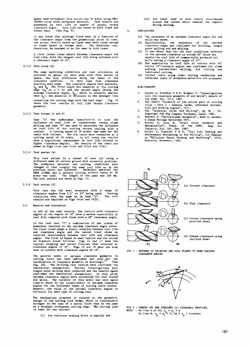
Examples of different grinding methods used to form various clearance shapes are shown in Fig. 1. It is assumed that the concave flank shape shown in Fig. l(a) is generated by the grinding wheel curvature.
to 1so.Zf
This
2.1
Ro "S"
S S
# m t "
VB
F C
ZC
a
af
a a:
L
Cutter outer radius SRP clearance Cutting edge Make of cutter straight clearance line Flank wear width mm Corner flank wear mm Cutting speed mlmin Co-ordinate axis and axis of rotation of m the tool and surface function General clearance angle Tool side clearance angle Lead angle Clearance measured on the PMC flank
Clearance measured on the straight flank Clearance angle measured at the cutting edge
Average clearance angle
Angle of rotation and co-ordinate in the moving system Surface inclination
flank shape was not investigated in this study since no theoretical justification could he found for the use of this shape of clearance profile in rotary cutting tools.
The flat flank shape depicted in Fig. I(b) appears to be simple to produce and the majority of manufacturers have, until recently, used this shape. Today, this shape is still to be found, albeit with two or more flats on the flank face.
The convex flank shown in Figs l(c) and (d) enables a constant clearance angle along the tool flank face to be achieved. (See Figs 2 and 3). In the previous study, this constant clearance profile, referred to as the Peripheral Milling Curve (PMC), was ground on single point cutters which were then tested and optimised.
It was considered too difficult to produce the PMC curve on actual end mills because of the spiral flutes and therefore the "eccentric grinding method", being geometrically the closest to the PMC shape, was selected for further investigations. The theoretical analysis shows a close relationship to the PMC method. In practical terms the geometric differences between the two curves is in the same order of magnitude as the production tolerances found in commercial tooling.
Geometric analysis
The "eccentric grinding" method has been defined by the kinematic and geometric relationship betwee wheel and the end mill being ground. observation of Fig. l(d) shows that this relative motion is similar to thread grinding. The resulting geometric surface 8 commonly known as "inclined straight screwed surface. If such a surface was ground with a curved grinding wheel it would then become an "inclined CuNed screwed surface". (See Fig. 4).
The "inclined 3raight screwed surface" has been defined mathematically and is known as SRP-I. It was used for drill point geometry having the following mathematical form:
?fhe g;;;:;;;
2 - c, 0 + c2 r + c3 ........................... (1)
Where 2, .$, r are the cylindrical co-ordinate axes of the tool system and C,, C2, C
Equation (1) was used to define the end mill clearance
are constants. 3
Annals of the CIRP Vol. 34/1/1985 1 49
2.1.1
2.2
geometry by solving for the constants C , C 2 , C from the following three boundary conditions fdr positions A, B and C in Fig. 5.
A. Z - 0 0 - 0 j r - R o
1 C. 2 = (Ro - Ri) tan v
where R - Outer tool radius Ro - Inner tool radius *i - Surface inclination L - Flute lead
Solving for the above-mentioned boundary conditions results in:
L 2 (r, Q) . 5 4 + (R - r) tan 0 .............. (3)
Equation (3 ) is the end mill clearance surface function.
Clearance angle calculation
The side clearance angle a depicted in Fig. 4 can be defined in any plane 2 - cOfnstant between line cc which is part of Z (r. 0) and the cutting speed vector Vc.
Substituting Z = C in equation (3) where C = constant, y ie Ids :
L - $ - c r(Q) - Ro + 2n tan ~
.......................... (4)
The side clearance angle can then be solved from the following derivative:
tan a = Ro .......................... (5)
which yields L
tan uf - 2 n Ro tan .......................... (6)
L .......................... (7) T q L
substituting in equation ( 6 ) finally yields
tan *.tan af - tan aL ......................... (8)
This function gives the relationship between the lead angle, the side clearance angle and the grinding wheel inclination angle (Fig. The result agre with published data concerning6) '"eccentric grinding'% and confirms the principle definitions in this section. The term "eccentric grinding" appears to be an incorrect description. since the surface is not eccentric. A more suitable description would be "inclined clearance grinding" which more adequately describes the method and SRP (Screw Relief Periphery) would be a more appropriate name for the geometry.
Comparisons between different clearance geometries
The following, commonly used clearance curves are considered for comparison with the PMC curve with the view to selecting the nearest curve to the PMC clearance geometry :
SRP - "S" Concave - "C" Flat - "t"
For the geometric comparison, a graphical presentation was used with the parameters selected so that at a particular point on the PMC curve, all the other curves will intersect and form the same side clearance angle, a which is measured relative to the cutting speed directlgfi at this point (Fig. 7(a)). In the previous study , this particular point was derived at the maximum clearance point where 0 - af in the case of the PMC type of clearance.
The selected criterion for the curve will be the variation in clearance angle along the tooth flank; the smaller the variation the better the geometry (see Figs 7(a) and 7(b)). Fig. 8(a) shows the general behaviour of the angle a relative to the angular distance. Fig. 8(b) shows an'enlarged view of the area of particular interest. It is apparent that curves "S" and "P" are very close to each other in the active area covered by the flank.
For example in the case of 10 m end mills in the region 0" - 12" the error between both curves is less than 4.5% or less than 0 ,5" (see Fig 8(b)). Thus both curves yield
3 .
3.1
3.2
3 .2 .1
3.2
3.2.1
3 . 3
almost a constant clearance of 10'. unlike the curves "C" and "t".
It may be concluded that both SRP and PMC curves show a fairly close geometric behaviour and can thus be regarded as curves that fulfil the condition of constant side clearance angles along the flanks of the cutter.
TESTS
Tests were carried out to confirm the existence of an optimum clearance angle of end mills and to establish the optimum clearance value for machining two different steels.
Test procedure
Machining conditions were selected so that approximately 6 passes of the test material could be machine$, before the defined end point of cutter life was reached. ) Two parameters were changed to meet these requirements: workpiece material and surface cutting speed. Surface cutting speed was either 20 m l m i n . or 30 mlmin. The feed rate was 0,025 mmltooth and the radial and axial depth of cut were each 5 mm. Tool life end point criteria were 0.14 mm flank wear and 0.4 nm corner wear.
Test Equipment
Cutters
Two basic cutter designs were supplied by three different manufacturers from three countries; flat flanks and eccentric ground flanks. The cutters were 10 mm diameter, four flute, standard length end mills, coded as P,H and S t o identify the various makes of cutters,
Particular care was taken during manufacture to ensure minimum scatter with regard to heat treatment, material variations, sizes and geometric variations. The cutters were divided into two groups i.e. flat and eccentric and further sub-divided into various clearance angles.
Workpiece material
Two types of steel, which were regarded as being within the range of common usage steels, were used; EN8K with a hardness of 210 HBN and EN24 with a hardness of 340 HBN. The size of test material was 580 nun long, 140 m n wide and 50 mm thick.
Machine tool and measuring equipment
A "Lagun" 2,2 kW universal milling machine with in- finitely variable spindle speed and table feed was used throughout the tests. The tool wear measurements were made using a tool room microscope fitted to the machine table. All measurements were made with the cutter in situ. By retaining the cutter in position (during measurement), actual cutting conditions are simulated more closely, resulting in more realistic wear propa- gation.
Geometric measurements of peripheral clearance were carried out on a special purpose rotary measuring machine constructed for this purpose.
Test results
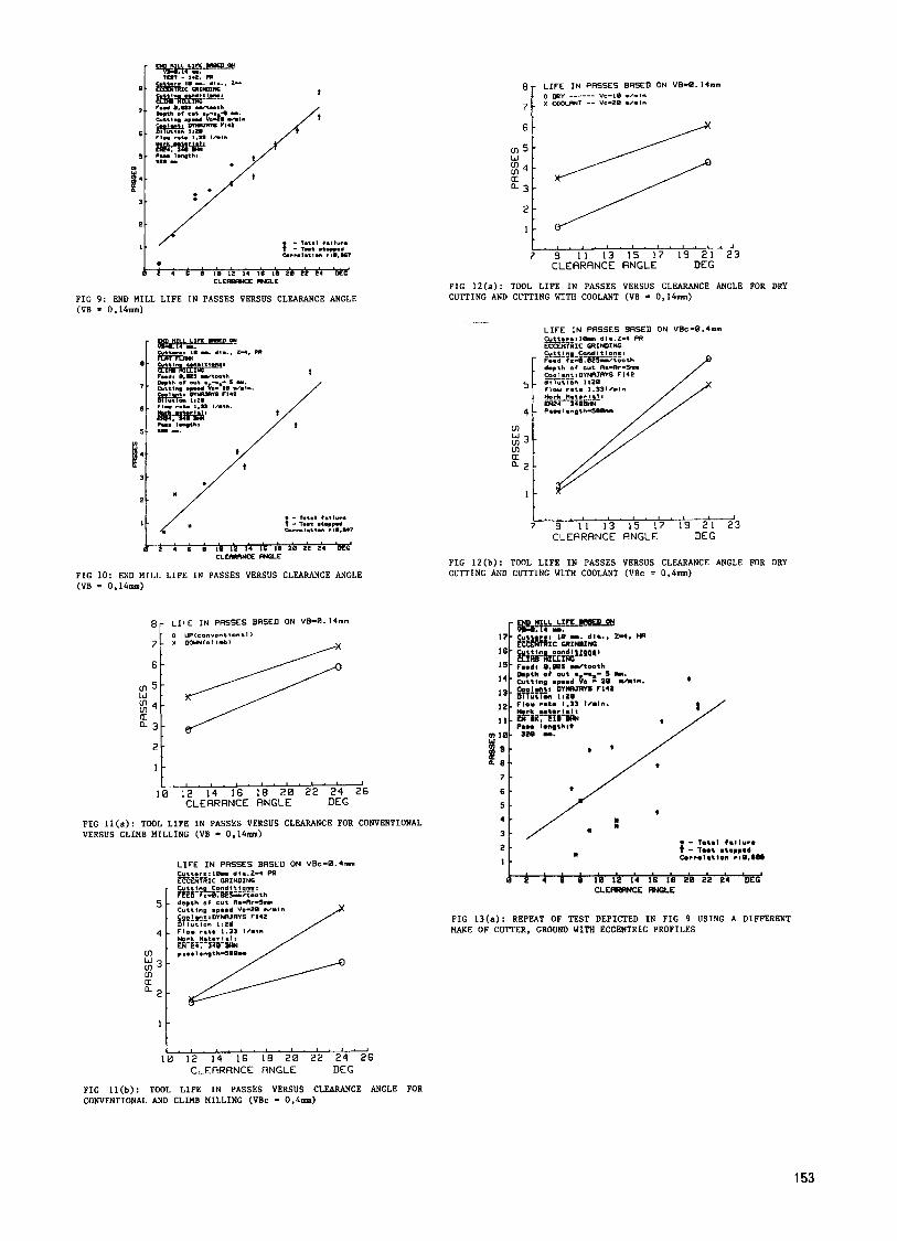
Table I shows six different groups of cutters that were used to optimise the peripheral clearance angles and to check the influence of flat versus eccentric ground cutters. Further tests were carried out to investigate the influence of up versus down milling and dry versus cutting with a coolant.
GROUP PUWOSE MAKE FLANK RANGE NO. OF GRAPH SHAPE af CUTTERS
(a) Optimisation P Eccentric 2,OO- 24' 18 10 (b) Optimisation P Flat 2,5*- 22O 9 I1 (c) Up versus
down P Eccentric I2,O'- 24" 4 (d) Dry versus
coolant P Eccentric 9,O"- 21: 4 ( e ) Optimisation H Eccentric 7,0°- 21 15 (f) Optimisation S Eccentric 3.0'- 31' 20
TABLE I : SELECTED TEST GROUP OF MILLING CUTTERS WITH REFERENCE TO TOOL LIFE GRAPHS
3.3.1 Test Group (a)
The eccentric ground cutters of this group were measured for tooth width and peripheral clearance angle. It was found that the clearance angles requested were within a deviation range of less than 0.5'. Tooth width varied from 1.2 mm to 1.4 m. The selected surface cutting
150
speed used throughout this series was 20 mlmin using EN24 340BHn alloy steel workpiece material. Test results are presented as tool life in number of passes versus clearance angle. Tool life was based on both flank and corner wear. (See Fig. 9).
It was found that although flank wear is a function of the clearance angle from the geometrical point of view, the actual results based on flank wear were close enough to those based on volume wear. The behaviour can, therefore, be assumed to be the same in both cases.
A clear linear trend exists between clearance angle and tool life, with the longest tool life being achieved with a clearance angle of 24'.
3.3.2 Test Group (b)
The same machining conditions and test procedures as outlined in group (a) were used with this series of tests, the only difference being the shape of the clearance profiles. In this case flat clearance profiles-were used. Two clearance angles were measured, a and a The first sngle was measured at the cutting e8ge ( a t a t r = R) and-the second angle (being the average clearance angle, a , which is normally smaller than uR), was measured in Aference to the straight line
connecting the cutting edge with the heel edge. Fig. 10 shows the test results of tool life versus clearance geometry .
3.3.3 Test Groups (c and d)
Test "c" was undertaken specifically to test the influence on tool life of conventional versus climb milling and test "d" was used to ascertain the influence on tool life of dry cutting versus cutting with a coolant. A cutting speed of 20 mlmin. was used for the tests with coolant. The dry tests were conducted at a cutting speed of 10 mlmin. In all tests the results show a significant improvement in tool life related to higher clearance angles. The results of the tests are shown in Figs Il(a) and Il(b) and 12(a) and 12(b).
3.3.4 Test series (e)
This test series is a repeat of test (a) using a different make of cutters ground with eccentric profiles. The workpiece material and cutting conditions were changed so that roughly the same tool life as in the previous tests was achieved. Workpiece material was EN8K 210BHn and a surface cutting surface speed of 30 mlmin was used. The length of the pass was 320 mm. The test results are shown in Fig. 13.
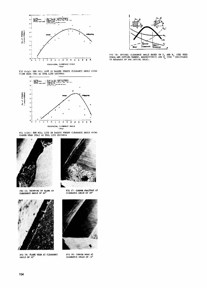
3.3.5 Test series (f)
This test was the most extensive with a range of clearance angles from 2.5' to 30' being used. Cutting conditions were the same as in Test "a". The test results are depicted in Figs 14(a) and 14(b).
3.4 Results and discussion
In all of the test results, the cutters with clearance angles at the region of 20' show s marked superiority in tool life compared with those with a 10' clearance angle.
In the last test "f" a combination of two trends of behaviour resulted in the optimum clearance angle curve. The first trend shows a direct relation between tool life and clearance angle and the second trend shows an inverted relationship between tool life and clearance angle. The first is based on wear failure and the second on fracture based failures Figs 15 and 17 show the typical chipping and corner fracture that occurred at clearance angles of 30'. Figs 16 and 18 show the even wear on cutters with clearance angles of 16'.
The general model of optimum clearance geometry in cutting tools has been published and used 5for the optimisation of clearance geometry in drilling). (See Fig. 20). The drilling test results have confirmed the theoretical assumptions. Further investigations into single point milling were conducted and the results again confirmed the theoretical assumptions. In this study optimum clearance angles were determined for four fluted end mills. The validity of this model was once again clearly shown by the establishment of optimum clearance angles for the different types of cutting tools tested. However, the value of the optimal clearance angles is different for each type of cutting tool.
The explanation proposed is related to the geometric design of the cutting tool wedge, which is considerably stronger in the case of a spiral flute than in the case of a straight orthogonal cutting edge. The cutting load is lower for two reasons:
(i) the resultant bending force is smaller and
(ii) the total load is more evenly distributed around the cutter which reduces the impacts during cutting.
4. CONCLUSIONS
(a) The existence of an optimum clearance angle for end mills was shown.
(b) Qualitatively, the existence of the optimum clearance angle was confirmed for drilling. single point milling and end milling.
(c) It was shown that for the test conditions referred to the optimum clearance is around 20' which may double the tool life of commercially produced end mills having a clearance angle of 10'.
(d) The superiority in tool life of cutters with 20' versus 10'clearance angles was confirmed for climb milling conventional milling, dry cutting and lubricated cutting.
(e) Further tests using other cutting conditions and different types of workpiece materials are proposed.
BIBLIOGRAPHY
I . Kaldor S. Trendler P H H, Hodgson T. "Investigations into the clearance geometry of end mills", Annals of the CIRP. Vol. 3311, 1984.
2. IS0 3002/1 "Geometry of the active part of cutting tools - Part I : General terms, reference systems, tool and working angles", 1977.
3. OSG "Technical Guide End Milling", pp 36 - 40. Copyright OSG Mfg Company Toyokawa, Japan, 1982.
4. Reutter F , "Darstellende Geomedrie". Band I, Aachen, G Braum Ferlage Karlsruhe 1972.
5. Kaldor 5 , Lenz E, "Drill Point Geometry and Optimisation", Trans. of the ASME. Eng. for Industry, Vol. 104, Feb. 1982.
6. Kaldor S, Trendler P H H, "Tool Life Testing and Performance Evaluating in End Milling", 5th Seminar on "Efficient Metal Forming and Machining", CSIR. Pretoria, November, 1983.
Y
(a) Concave clearance
(b) Flat clearance
(c) Convex clearance using profiled wheel
(d) Convex clearance using inclined wheel
- 4 FIG I : METHODS OF GRINDING END MILL FLANKS TO FORM VARIOUS
CLEARANCE ANGLES
FIG 2 : CONVEX (P) AND STRAIGHT (t) CLEARANCE PROFILES. NOTE : On line A at CE. a - at - 0
On line B, a - at'- 0, on P a = constant P P
151
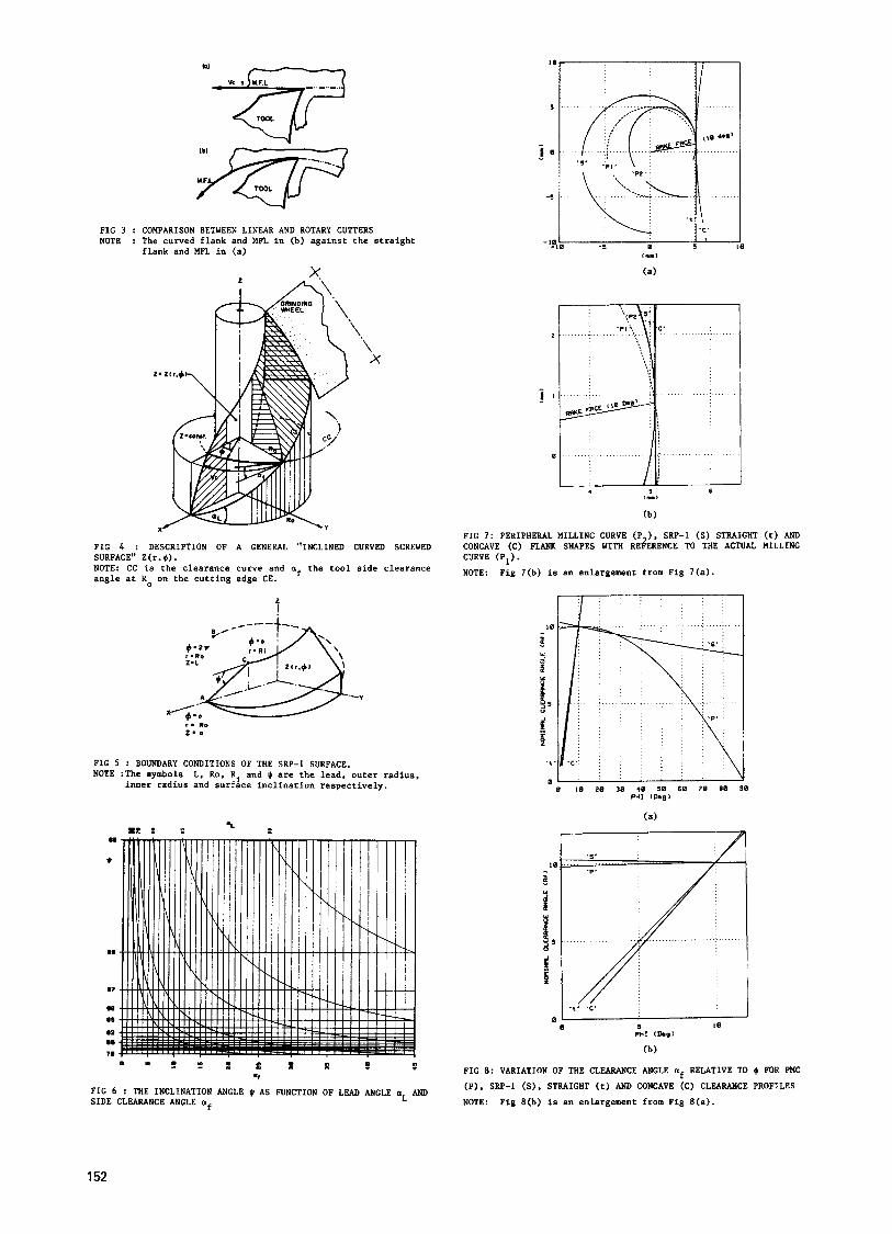
F I G 3 : COMPARISON BETWEEN LINEAR AND ROTARY CUTTERS NOTE : The curved flank and MFL in (b) against the straight
flank and HFL in (a)
T A\
F I G 4 : DESCRIPTION O F A GENERAL "INCLINED CURVED SCREWED SURFACE" Z(r. $). NOTE: CC is the clearance curve and af the tool side clearance angle at R on the cutting edge CE.
2 I
F I G 5 : BOUNDARY CONDITIONS O F THE SRF-I SURFACE. NOTE :The symbols L. Ro, R and Q are the lead, outer radius,
inner radius and surfhe inclination respectively.
m . e l " Y
t m
F I G 6 : THE INCLINATION ANGLE 0 A S FUNCTION O F LEAD ANGLE aL AND S I D E CLEARANCE ANGLE af
F I G 7: PERIPHERAL MILLING CURVE (F ), SRP-1 (S) STRAIGHT ( t ) AND
CURVE (P I ) . CONCAVE (c) FLANK SHAPES WITH R E ~ R E N C E TO THE ACTUAL MILLING
NOTE: Fig 7(b) is an enlargement from Fig 7(a).
F I G 8: VARIATION OF THE CLEARANCE ANGLE af RELATIVE TO + FOR FMC
(P). SRP-I (S). STRAIGHT (t) AND CONCAVE (C) CLEARANCE P R O F I L E S
NOTE: Fig 8(b) is an enlargement from Fig 8(a).
1 52
a -
7 -
6 -
S - 1,. 3 -
2 -
I -
5 -
4 -
ffl
ffl U
: 3 -
a 2 -
I -
rm - 1.2. CI
FIG 9: END MILL LIFE I N PASSES VERSUS CLEARANCE ANGLE (VB = 0,14mm)
I-
7 -
6 -
S. VI
f 4 - 3 -
2 -
1 -
FIG 10: END MILL LIFE I N PASSES VERSUS CLEARANCE ANGLE (VB = 0,14m)
8 - L I F E I N PRSSES BRSED ON VB-8.14mm ' 0 "P<s.nr.ntlon.l>
7 - X 00UNlcl+mbI
w
U ' a 3 -
2l 1
t . t . ~ . ' . ' . ' ' " ' ' ~
I 0 12 14 16 18 2 0 2 2 2 4 2 6 CLERRRNCE RNGLE DEG
FIG I l ( a ) : TOOL LIFE I N PASSES VERSUS CLEARANCE FOR CONVENTIONAL VERSUS CLIMB MILLING (VB = 0.14mm)
I . I . I . t . I . I . ( . " I
10 12 14 16 1E 2 0 2 2 2 4 2 6 CLERRRNCE RNGLE UEG
FIG I I ( b ) : TOOL LIFE I N PASSES VERSUS CLEARANCE ANGLE FOR CONVENTIONAL AND CLIMB MILLING (VBc = 0,4mm)
L I F E I N PRSSES BRSED ON VB-B.14mm
x COOCRNT -- Vc-20 m l - I n 0 my ------ vs-10 m/n,n
7 9 - 1 1 13 15 17 19 2 1 2 3 CLEARRNCE RNGLE DEG
FIG 12(a): TOOL LIFE I N PASSES VERSUS CLEARANCE ANGLE FOR DRY CUTTING AND CUTTING WITH COOLANT (VB = 0,14m)
PIG 1Z(b): TOOL LIFE IN PASSES VERSUS CLEARANCE ANGLE FOR DRY CUTTING AND CUTTING WITH COOLANT (VBc = 0 , 4 m )
w I 9
7
6
5
4
3
2
I
2 4 6 8 I0 12 14 16 18 2 8 22 24 DEG I
CLERRANCE ANGLE
FIG 13(a): REPEAT OF TEST DEPICTED I N FIG 9 USING A DIFFERENT MAKE OF CUTTER, GROUND WITH ECCENTRIC PROFILES
153
" 1 ' / j . . ... m e . . a m = . t : z Z z : : : : $
0 - - ' ' ' ' ' - PERIPHERFL CLEARRNCE RNGLE
( d o g )
FIG 1 4 ( a ) : END MILL LIFE IN PASSES VERSUS CLEARANCE ANGLE USING FLANK WEAR (VB) AS TOOL LIFE CRITERIA
PERIPHERAL CLERRRNCE RNGLE l d e g l
FIG 14(b): END MILL LIFE IN PASSES VERSUS CLEARANCE ANGLE USING CORNER WEAR (VBc) AS TOOL LIFE CRITERIA
FIG 1 5 : CRIPPING OF FLANK AT CLEARANCE ANGLE OF 30"
FIG 17: CORNER FRACTURE AT CLEARANCE ANGLE OF 30'
FIG 19: OPTIMAL CLEARANCE ANGLE BASED ON F AND Mc (THE FEED FORCE AND CUTTING MOMENT. RESPECTIVELY) AND f (THE RESISTANCE TO BREAKAGE OF THE CUTTING EDGE).
FIG 16: FLANK WEAR AT CLEARANCE FIG 18: CORNER WEAR AT ANGLE OF 16" CLEARANCE ANLGE OF 16'
154