Embed Size (px)
Citation preview
IOC-01, IOC-02 and IOC-03 ModuleMódulo IOC-01, IOC-02 y IOC-03Módulo IOC-01, IOC-02 e IOC-03
Installation, Configuration and Operation GuideGuía de Instalación, Configuración y Operación Guia de Instalação, Configuração e Operação
English / Español / Português
Motors | Automation | Energy | Transmission & Distribution | Coatings

Summary / Índice
SUMMARY
1. SAFETY INFORMATION ......................................................................................................5
2. GENERAL INFORMATION ..................................................................................................5
3. PACKAGE CONTENTS ........................................................................................................5
4. MODULE INSTALLATION....................................................................................................5
5. TECHNICAL SPECIFICATIONS ..........................................................................................75.1 Connection and Indications ..................................................................................................... 7
6. OPERATION ........................................................................................................................12
ÍNDICE
1. INFORMACIONES DE SEGURIDAD .................................................................................13
2. INFORMACIONES GENERALES ......................................................................................13
3. CONTENIDO DEL EMBALAJE .........................................................................................13
4. INSTALACCIÓN DE LOS MÓDULOS ...............................................................................13
5. ESPECIFICACIONES TÉCNICAS .....................................................................................155.1 Conexión y Señalizaciones .................................................................................................... 15
6. PUESTA EN MARCHA ...................................................................................................... 20
ÍNDICE
1. INFORMAÇÕES DE SEGURANÇA ...................................................................................21
2. INFORMAÇÕES GERAIS ..................................................................................................21
3. CONTEÚDO DA EMBALAGEM .........................................................................................21
4. INSTALAÇÃO DOS MÓDULOS .........................................................................................21
5. ESPECIFICAÇÕES TÉCNICAS ........................................................................................ 235.1 Conexões e Indicações .......................................................................................................... 23
6. COLOCAÇÃO EM FUNCIONAMENTO ............................................................................ 28

Installation, Configuration and operation guide
5
1. SAFETY INFORMATION
All safety procedures described in the manual must be followed.
2. GENERAL INFORMATION
This user guide provides information for installation, configuration and operation of the optional modules IOC-01, IOC-02 and IOC-03.These modules are dedicated to the expansion of digital inputs and outputs in Soft-PLC applications.
NOTE!The IOC-01 and IOC-02 accessories can be used only with CFW-11 inverters that have software version V2.00 or higher. The IOC-03 accessory can be used only with CFW-11 inverters that have software version V3.10 or higher.
3. PACKAGE CONTENTS
� Accessory module in anti-static packaging. � Installation, configuration and operation guide. � Fixing screw.
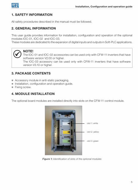
4. MODULE INSTALLATION
The optional board modules are installed directly into slots on the CFW-11 control module.
- slot 1: white
- slot 2: yellow
- slot 3: green
Figure 1: Identification of slots of the optional modules
Installation, Configuration and operation guide
6
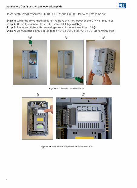
To correctly install modules IOC-01, IOC-02 and IOC-03, follow the steps below:
Step 1: While the drive is powered off, remove the front cover of the CFW-11 (figure 2).Step 2: Carefully connect the module into slot 1 (figure 3(a)).Step 3: Place and tighten the securing screw of the module (figure 3(b)).Step 4: Connect the signal cables to the XC15 (IOC-01) or XC16 (IOC-02) terminal strip.
b ca
Figure 2: Removal of front cover
ba
Figure 3: Installation of optional module into slot
Installation, Configuration and operation guide
7
5. TECHNICAL SPECIFICATIONS
5.1 CONNECTION AND INDICATIONS
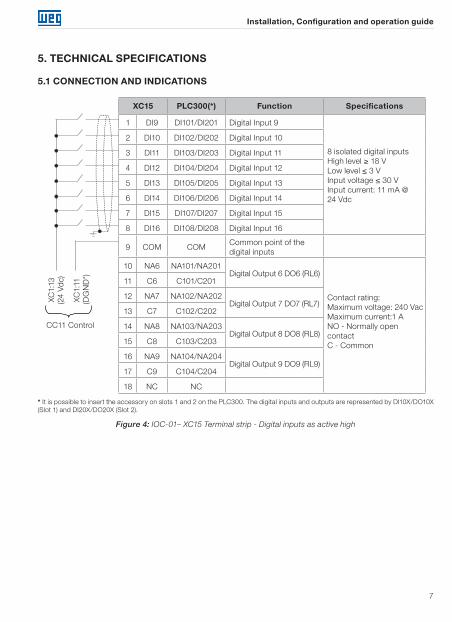
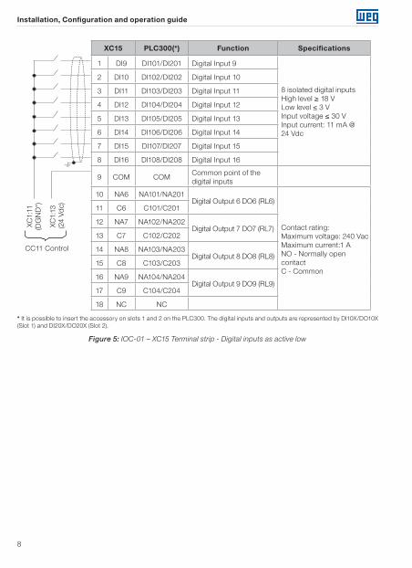
XC15 PLC300(*) Function Specifications
1 DI9 DI101/DI201 Digital Input 9
8 isolated digital inputsHigh level ≥ 18 VLow level ≤ 3 V Input voltage ≤ 30 VInput current: 11 mA @ 24 Vdc
2 DI10 DI102/DI202 Digital Input 10
3 DI11 DI103/DI203 Digital Input 11
4 DI12 DI104/DI204 Digital Input 12
5 DI13 DI105/DI205 Digital Input 13
6 DI14 DI106/DI206 Digital Input 14
7 DI15 DI107/DI207 Digital Input 15
8 DI16 DI108/DI208 Digital Input 16
9 COM COMCommon point of the digital inputs
10 NA6 NA101/NA201Digital Output 6 DO6 (RL6)
Contact rating:Maximum voltage: 240 VacMaximum current:1 ANO - Normally open contact C - Common
11 C6 C101/C201
12 NA7 NA102/NA202Digital Output 7 DO7 (RL7)
13 C7 C102/C202
14 NA8 NA103/NA203Digital Output 8 DO8 (RL8)
15 C8 C103/C203
16 NA9 NA104/NA204Digital Output 9 DO9 (RL9)
17 C9 C104/C204
18 NC NC
CC11 Control
XC1:
13(2
4 Vd
c)
XC1:
11(D
GN
D*)
* It is possible to insert the accessory on slots 1 and 2 on the PLC300. The digital inputs and outputs are represented by DI10X/DO10X (Slot 1) and DI20X/DO20X (Slot 2).
Figure 4: IOC-01– XC15 Terminal strip - Digital inputs as active high
Installation, Configuration and operation guide
8
XC15 PLC300(*) Function Specifications
1 DI9 DI101/DI201 Digital Input 9
8 isolated digital inputsHigh level ≥ 18 VLow level ≤ 3 V Input voltage ≤ 30 VInput current: 11 mA @ 24 Vdc
2 DI10 DI102/DI202 Digital Input 10
3 DI11 DI103/DI203 Digital Input 11
4 DI12 DI104/DI204 Digital Input 12
5 DI13 DI105/DI205 Digital Input 13
6 DI14 DI106/DI206 Digital Input 14
7 DI15 DI107/DI207 Digital Input 15
8 DI16 DI108/DI208 Digital Input 16
9 COM COMCommon point of the digital inputs
10 NA6 NA101/NA201Digital Output 6 DO6 (RL6)
Contact rating:Maximum voltage: 240 VacMaximum current:1 ANO - Normally open contact C - Common
11 C6 C101/C201
12 NA7 NA102/NA202Digital Output 7 DO7 (RL7)
13 C7 C102/C202
14 NA8 NA103/NA203Digital Output 8 DO8 (RL8)
15 C8 C103/C203
16 NA9 NA104/NA204Digital Output 9 DO9 (RL9)
17 C9 C104/C204
18 NC NC
CC11 Control
XC1:
11(D
GN
D*)
XC1:
13(2
4 Vd
c)
* It is possible to insert the accessory on slots 1 and 2 on the PLC300. The digital inputs and outputs are represented by DI10X/DO10X (Slot 1) and DI20X/DO20X (Slot 2).
Figure 5: IOC-01 – XC15 Terminal strip - Digital inputs as active low
Installation, Configuration and operation guide
9
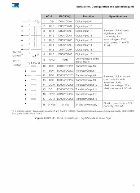
XC16 PLC300(*) Function Specifications
1 DI9 DI101/DI201 Digital Input 9
8 isolated digital inputsHigh level ≥ 18 VLow level ≤ 3 V Input voltage ≤ 30 VInput current: 11 mA @ 24 Vdc
2 DI10 DI102/DI202 Digital Input 10
3 DI11 DI103/DI203 Digital Input 11
4 DI12 DI104/DI204 Digital Input 12
5 DI13 DI105/DI205 Digital Input 13
6 DI14 DI106/DI206 Digital Input 14
7 DI15 DI107/DI207 Digital Input 15
8 DI16 DI108/DI208 Digital Input 16
9 COM COMCommon point of the digital inputs
10 DO6 DO101/DO201 Transistor Output 6
8 isolated digital outputs, open collector with freewheel diodeMaximum voltage: 24 VMaximum current: 50 mA
11 DO7 DO102/DO202 Transistor Output 7
12 DO8 DO103/DO203 Transistor Output 8
13 DO9 DO104/DO204 Transistor Output 9
14 DO10 DO105/DO205 Transistor Output 10
15 DO11 DO106/DO206 Transistor Output 11
16 DO12 DO107/DO207 Transistor Output 12
17 DO13 DO108/DO208 Transistor Output 13
18 24 Vdc 24 Vcc 24 Vdc power suply24 Vdc power suply, ± 8 %. Capacity: 500 mA
XC1:13
XC1:11RL ≥ 500 Ω
(24 Vdc)
(DGND*)
* It is possible to insert the accessory on slots 1 and 2 on the PLC300. The digital inputs and outputs are represented by DI10X/DO10X (Slot 1) and DI20X/DO20X (Slot 2).
Figure 6: IOC-02 – XC16 Terminal strip – Digital inputs as active high
Installation, Configuration and operation guide
10
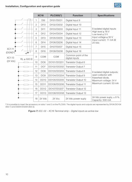
XC16 PLC300(*) Function Specifications
1 DI9 DI101/DI201 Digital Input 9
8 isolated digital inputsHigh level ≥ 18 VLow level ≤ 3 V Input voltage ≤ 30 VInput current: 11 mA @ 24 Vdc
2 DI10 DI102/DI202 Digital Input 10
3 DI11 DI103/DI203 Digital Input 11
4 DI12 DI104/DI204 Digital Input 12
5 DI13 DI105/DI205 Digital Input 13
6 DI14 DI106/DI206 Digital Input 14
7 DI15 DI107/DI207 Digital Input 15
8 DI16 DI108/DI208 Digital Input 16
9 COM COMCommon point of the digital inputs
10 DO6 DO101/DO201 Transistor Output 6
8 isolated digital outputs, open collector with freewheel diode.Maximum voltage: 24 VMaximum current: 50 mA
11 DO7 DO102/DO202 Transistor Output 7
12 DO8 DO103/DO203 Transistor Output 8
13 DO9 DO104/DO204 Transistor Output 9
14 DO10 DO105/DO205 Transistor Output 10
15 DO11 DO106/DO206 Transistor Output 11
16 DO12 DO107/DO207 Transistor Output 12
17 DO13 DO108/DO208 Transistor Output 13
18 24 Vdc 24 Vcc 24 Vdc power suply24 Vdc power suply, ± 8 %. Capacity: 500 mA
XC1:11
XC1:13RL ≥ 500 Ω
(DGND*)
(24 Vdc)
* It is possible to insert the accessory on slots 1 and 2 on the PLC300. The digital inputs and outputs are represented by DI10X/DO10X (Slot 1) and DI20X/DO20X (Slot 2).
Figure 7: IOC-02 – XC16 Terminal strip – Digital inputs as active low
Installation, Configuration and operation guide
11
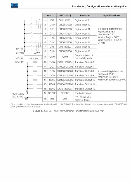
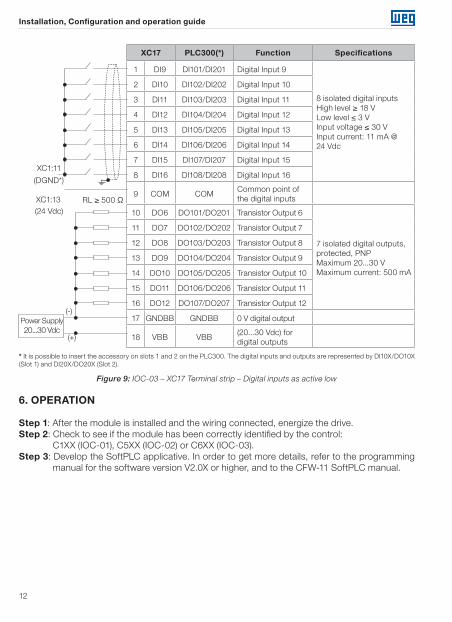
XC17 PLC300(*) Function Specifications
1 DI9 DI101/DI201 Digital Input 9
8 isolated digital inputsHigh level ≥ 18 VLow level ≤ 3 V Input voltage ≤ 30 VInput current: 11 mA @ 24 Vdc
2 DI10 DI102/DI202 Digital Input 10
3 DI11 DI103/DI203 Digital Input 11
4 DI12 DI104/DI204 Digital Input 12
5 DI13 DI105/DI205 Digital Input 13
6 DI14 DI106/DI206 Digital Input 14
7 DI15 DI107/DI207 Digital Input 15
8 DI16 DI108/DI208 Digital Input 16
9 COM COMCommon point of the digital inputs
10 DO6 DO101/DO201 Transistor Output 6
7 isolated digital outputs, protected, PNPMaximum 20...30 VMaximum current: 500 mA
11 DO7 DO102/DO202 Transistor Output 7
12 DO8 DO103/DO203 Transistor Output 8
13 DO9 DO104/DO204 Transistor Output 9
14 DO10 DO105/DO205 Transistor Output 10
15 DO11 DO106/DO206 Transistor Output 11
16 DO12 DO107/DO207 Transistor Output 12
17 GNDBB GNDBB 0 V digital output
18 VBB VBB(20...30 Vdc) for digital outputs
RL ≥ 500 Ω
XC1:13
(24 Vdc)
XC1:11(DGND*)
Power Supply 20...30 Vdc
(-)
(+)
* It is possible to insert the accessory on slots 1 and 2 on the PLC300. The digital inputs and outputs are represented by DI10X/DO10X (Slot 1) and DI20X/DO20X (Slot 2).
Figure 8: IOC-03 – XC17 Terminal strip – Digital inputs as active high
Installation, Configuration and operation guide
12
XC17 PLC300(*) Function Specifications
1 DI9 DI101/DI201 Digital Input 9
8 isolated digital inputsHigh level ≥ 18 VLow level ≤ 3 V Input voltage ≤ 30 VInput current: 11 mA @ 24 Vdc
2 DI10 DI102/DI202 Digital Input 10
3 DI11 DI103/DI203 Digital Input 11
4 DI12 DI104/DI204 Digital Input 12
5 DI13 DI105/DI205 Digital Input 13
6 DI14 DI106/DI206 Digital Input 14
7 DI15 DI107/DI207 Digital Input 15
8 DI16 DI108/DI208 Digital Input 16
9 COM COMCommon point of the digital inputs
10 DO6 DO101/DO201 Transistor Output 6
7 isolated digital outputs, protected, PNPMaximum 20...30 VMaximum current: 500 mA
11 DO7 DO102/DO202 Transistor Output 7
12 DO8 DO103/DO203 Transistor Output 8
13 DO9 DO104/DO204 Transistor Output 9
14 DO10 DO105/DO205 Transistor Output 10
15 DO11 DO106/DO206 Transistor Output 11
16 DO12 DO107/DO207 Transistor Output 12
17 GNDBB GNDBB 0 V digital output
18 VBB VBB(20...30 Vdc) for digital outputs
RL ≥ 500 Ω
XC1:11
(DGND*)
XC1:13(24 Vdc)
Power Supply 20...30 Vdc
(-)
(+)
* It is possible to insert the accessory on slots 1 and 2 on the PLC300. The digital inputs and outputs are represented by DI10X/DO10X (Slot 1) and DI20X/DO20X (Slot 2).
Figure 9: IOC-03 – XC17 Terminal strip – Digital inputs as active low
6. OPERATION
Step 1: After the module is installed and the wiring connected, energize the drive.Step 2: Check to see if the module has been correctly identified by the control:
C1XX (IOC-01), C5XX (IOC-02) or C6XX (IOC-03).Step 3: Develop the SoftPLC applicative. In order to get more details, refer to the programming
manual for the software version V2.0X or higher, and to the CFW-11 SoftPLC manual.
Guía de instalación, configuración y operación
13
1. INFORMACIONES DE SEGURIDAD
Todos los procedimientos de seguridad descriptos en el manual deben ser seguidos.
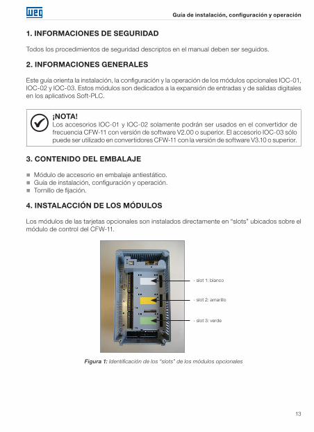
2. INFORMACIONES GENERALES
Este guía orienta la instalación, la configuración y la operación de los módulos opcionales IOC-01, IOC-02 y IOC-03. Estos módulos son dedicados a la expansión de entradas y de salidas digitales en los aplicativos Soft-PLC.
¡NOTA!Los accesorios IOC-01 y IOC-02 solamente podrán ser usados en el convertidor de frecuencia CFW-11 con versión de software V2.00 o superior. El accesorio IOC-03 sólo puede ser utilizado en convertidores CFW-11 con la versión de software V3.10 o superior.
3. CONTENIDO DEL EMBALAJE
� Módulo de accesorio en embalaje antiestático. � Guía de instalación, configuración y operación. � Tornillo de fijación.
4. INSTALACCIÓN DE LOS MÓDULOS
Los módulos de las tarjetas opcionales son instalados directamente en “slots” ubicados sobre el módulo de control del CFW-11.
- slot 1: blanco
- slot 2: amarillo
- slot 3: verde
Figura 1: Identificación de los “slots” de los módulos opcionales

Guía de instalación, configuración y operación
14
Para la correcta instalación de los módulos IOC-01, IOC-02 y IOC-03, siga los siguientes pasos:
Paso 1: Con el convertidor sin corriente, quitar la tapa frontal del CFW-11 (figura 2).Paso 2: Enclave cuidadosamente el módulo en el “slot 1” (figura 3(a)).Paso 3: Coloque y apriete el tornillo de puesta a la tierra del módulo (Figura 3(b)).Paso 4: Conecte los cables de señal en los conectores XC15 (IOC-01) o XC16 (IOC-02).
b ca
Figura 2: Remoción de la tapa frontal
ba
Figura 3: Instalación del módulo opcional en el “slot”
Guía de instalación, configuración y operación
15
5. ESPECIFICACIONES TÉCNICAS
5.1 CONEXIÓN Y SEÑALIZACIONES
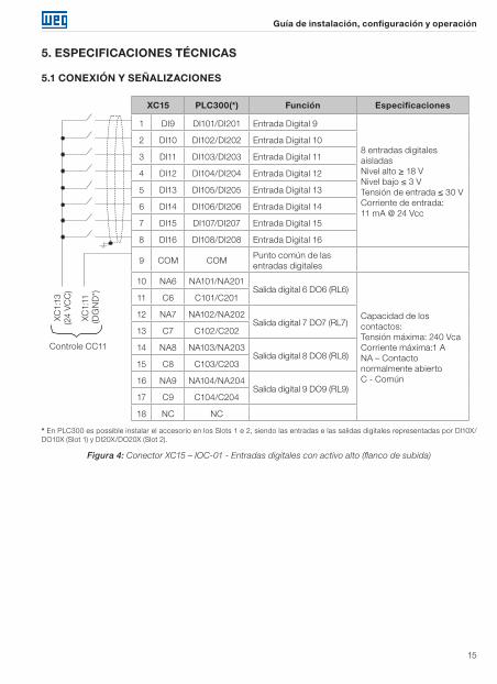
XC15 PLC300(*) Función Especificaciones
1 DI9 DI101/DI201 Entrada Digital 9
8 entradas digitales aisladasNivel alto ≥ 18 V Nivel bajo ≤ 3 V Tensión de entrada ≤ 30 VCorriente de entrada: 11 mA @ 24 Vcc
2 DI10 DI102/DI202 Entrada Digital 10
3 DI11 DI103/DI203 Entrada Digital 11
4 DI12 DI104/DI204 Entrada Digital 12
5 DI13 DI105/DI205 Entrada Digital 13
6 DI14 DI106/DI206 Entrada Digital 14
7 DI15 DI107/DI207 Entrada Digital 15
8 DI16 DI108/DI208 Entrada Digital 16
9 COM COMPunto común de las entradas digitales
10 NA6 NA101/NA201Salida digital 6 DO6 (RL6)
Capacidad de los contactos:Tensión máxima: 240 VcaCorriente máxima:1 ANA – Contacto normalmente abiertoC - Común
11 C6 C101/C201
12 NA7 NA102/NA202Salida digital 7 DO7 (RL7)
13 C7 C102/C202
14 NA8 NA103/NA203Salida digital 8 DO8 (RL8)
15 C8 C103/C203
16 NA9 NA104/NA204Salida digital 9 DO9 (RL9)
17 C9 C104/C204
18 NC NC
Controle CC11
XC1:
13(2
4 V
CC
)
XC1:
11(D
GN
D*)
* En PLC300 es possible instalar el accesorio en los Slots 1 e 2, siendo las entradas e las salidas digitales representadas por DI10X/DO10X (Slot 1) y DI20X/DO20X (Slot 2).
Figura 4: Conector XC15 – IOC-01 - Entradas digitales con activo alto (flanco de subida)
Guía de instalación, configuración y operación
16
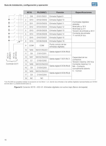
XC15 PLC300(*) Función Especificaciones
1 DI9 DI101/DI201 Entrada Digital 9
8 entradas digitales aisladasNivel alto ≥ 18 V Nivel bajo ≤ 3 V Tensión de entrada ≤ 30 VCorriente de entrada: 11 mA @ 24 Vcc
2 DI10 DI102/DI202 Entrada Digital 10
3 DI11 DI103/DI203 Entrada Digital 11
4 DI12 DI104/DI204 Entrada Digital 12
5 DI13 DI105/DI205 Entrada Digital 13
6 DI14 DI106/DI206 Entrada Digital 14
7 DI15 DI107/DI207 Entrada Digital 15
8 DI16 DI108/DI208 Entrada Digital 16
9 COM COMPunto común de las entradas digitales
10 NA6 NA101/NA201Salida digital 6 DO6 (RL6)
Capacidad de los contactos:Tensión máxima: 240 VcaCorriente máxima:1 ANA – Contacto normalmente abiertoC - Común
11 C6 C101/C201
12 NA7 NA102/NA202Salida digital 7 DO7 (RL7)
13 C7 C102/C202
14 NA8 NA103/NA203Salida digital 8 DO8 (RL8)
15 C8 C103/C203
16 NA9 NA104/NA204Salida digital 9 DO9 (RL9)
17 C9 C104/C204
18 NC NC
Controle CC11
XC1:
11(D
GN
D*)
XC1:
13(2
4 V
CC
)
* En PLC300 es possible instalar el accesorio en los Slots 1 e 2, siendo las entradas e las salidas digitales representadas por DI10X/DO10X (Slot 1) y DI20X/DO20X (Slot 2).
Figura 5: Conector XC15 – IOC-01- Entradas digitales con activo bajo (flanco de bajada)

Guía de instalación, configuración y operación
17
XC16 PLC300(*) Función Especificaciones
1 DI9 DI101/DI201 Entrada Digital 9
8 entradas digitales aisladasNivel alto ≥ 18 V Nivel bajo ≤ 3 VTensión de entrada ≤ 30 VCorriente de entrada: 11 mA @ 24 Vcc
2 DI10 DI102/DI202 Entrada Digital 10
3 DI11 DI103/DI203 Entrada Digital 11
4 DI12 DI104/DI204 Entrada Digital 12
5 DI13 DI105/DI205 Entrada Digital 13
6 DI14 DI106/DI206 Entrada Digital 14
7 DI15 DI107/DI207 Entrada Digital 15
8 DI16 DI108/DI208 Entrada Digital 16
9 COM COMPunto común de las entradas digitales
10 DO6 DO101/DO201 Salida a Transistor 6
8 salidas digitales aisladas,Colector abierto con diodo de rueda libreTensión máxima: 24 VCorriente máxima: 50 mA
11 DO7 DO102/DO202 Salida a Transistor 7
12 DO8 DO103/DO203 Salida a Transistor 8
13 DO9 DO104/DO204 Salida a Transistor 9
14 DO10 DO105/DO205 Salida a Transistor 10
15 DO11 DO106/DO206 Salida a Transistor 11
16 DO12 DO107/DO207 Salida a Transistor 12
17 DO13 DO108/DO208 Salida a Transistor 13
18 24 Vcc 24 Vcc Fuente 24 VccFuente de alimentación24 Vcc ± 8 % Capacidad: 500 mA
XC1:13
XC1:11RL ≥ 500 Ω
(24 VCC)
(DGND*)
* En PLC300 es possible instalar el accesorio en los Slots 1 e 2, siendo las entradas e las salidas digitales representadas por DI10X/DO10X (Slot 1) y DI20X/DO20X (Slot 2).
Figura 6: Conector XC16 – IOC-02 – Entradas digitales con activo alto (flanco de subida)
Guía de instalación, configuración y operación
18
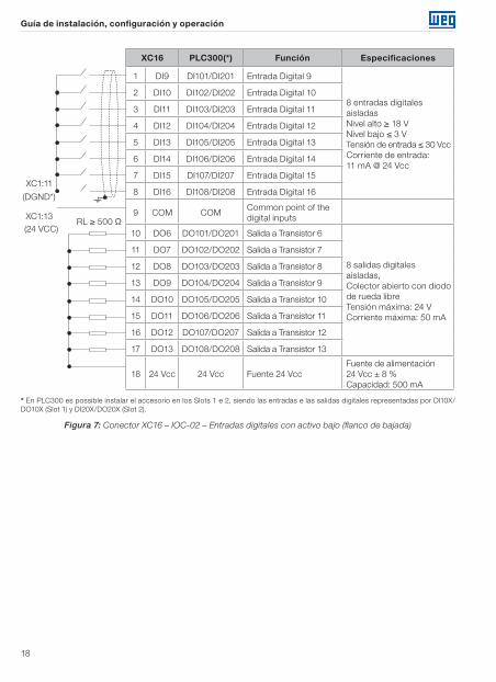
XC16 PLC300(*) Función Especificaciones
1 DI9 DI101/DI201 Entrada Digital 9
8 entradas digitales aisladasNivel alto ≥ 18 V Nivel bajo ≤ 3 VTensión de entrada ≤ 30 VccCorriente de entrada: 11 mA @ 24 Vcc
2 DI10 DI102/DI202 Entrada Digital 10
3 DI11 DI103/DI203 Entrada Digital 11
4 DI12 DI104/DI204 Entrada Digital 12
5 DI13 DI105/DI205 Entrada Digital 13
6 DI14 DI106/DI206 Entrada Digital 14
7 DI15 DI107/DI207 Entrada Digital 15
8 DI16 DI108/DI208 Entrada Digital 16
9 COM COMCommon point of the digital inputs
10 DO6 DO101/DO201 Salida a Transistor 6
8 salidas digitales aisladas,Colector abierto con diodo de rueda libreTensión máxima: 24 VCorriente máxima: 50 mA
11 DO7 DO102/DO202 Salida a Transistor 7
12 DO8 DO103/DO203 Salida a Transistor 8
13 DO9 DO104/DO204 Salida a Transistor 9
14 DO10 DO105/DO205 Salida a Transistor 10
15 DO11 DO106/DO206 Salida a Transistor 11
16 DO12 DO107/DO207 Salida a Transistor 12
17 DO13 DO108/DO208 Salida a Transistor 13
18 24 Vcc 24 Vcc Fuente 24 VccFuente de alimentación24 Vcc ± 8 % Capacidad: 500 mA
XC1:11
XC1:13RL ≥ 500 Ω
(DGND*)
(24 VCC)
* En PLC300 es possible instalar el accesorio en los Slots 1 e 2, siendo las entradas e las salidas digitales representadas por DI10X/DO10X (Slot 1) y DI20X/DO20X (Slot 2).
Figura 7: Conector XC16 – IOC-02 – Entradas digitales con activo bajo (flanco de bajada)
Guía de instalación, configuración y operación
19
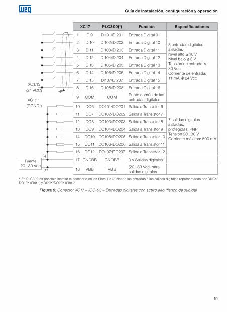
XC17 PLC300(*) Función Especificaciones
1 DI9 DI101/DI201 Entrada Digital 9
8 entradas digitales aisladasNivel alto ≥ 18 V Nivel bajo ≤ 3 VTensión de entrada ≤ 30 VccCorriente de entrada: 11 mA @ 24 Vcc
2 DI10 DI102/DI202 Entrada Digital 10
3 DI11 DI103/DI203 Entrada Digital 11
4 DI12 DI104/DI204 Entrada Digital 12
5 DI13 DI105/DI205 Entrada Digital 13
6 DI14 DI106/DI206 Entrada Digital 14
7 DI15 DI107/DI207 Entrada Digital 15
8 DI16 DI108/DI208 Entrada Digital 16
9 COM COMPunto común de las entradas digitales
10 DO6 DO101/DO201 Salida a Transistor 6
7 salidas digitales aisladas,protegidas, PNPTensión 20...30 VCorriente máxima: 500 mA
11 DO7 DO102/DO202 Salida a Transistor 7
12 DO8 DO103/DO203 Salida a Transistor 8
13 DO9 DO104/DO204 Salida a Transistor 9
14 DO10 DO105/DO205 Salida a Transistor 10
15 DO11 DO106/DO206 Salida a Transistor 11
16 DO12 DO107/DO207 Salida a Transistor 12
17 GNDBB GNDBB 0 V Salidas digitales
18 VBB VBB(20...30 Vcc) para salidas digitales
XC1:13
(24 VCC)
XC1:11(DGND*)
Fuente 20...30 Vdc
(-)
(+)
* En PLC300 es possible instalar el accesorio en los Slots 1 e 2, siendo las entradas e las salidas digitales representadas por DI10X/DO10X (Slot 1) y DI20X/DO20X (Slot 2).
Figura 8: Conector XC17 – IOC-03 – Entradas digitales con activo alto (flanco de subida)
Guía de instalación, configuración y operación
20
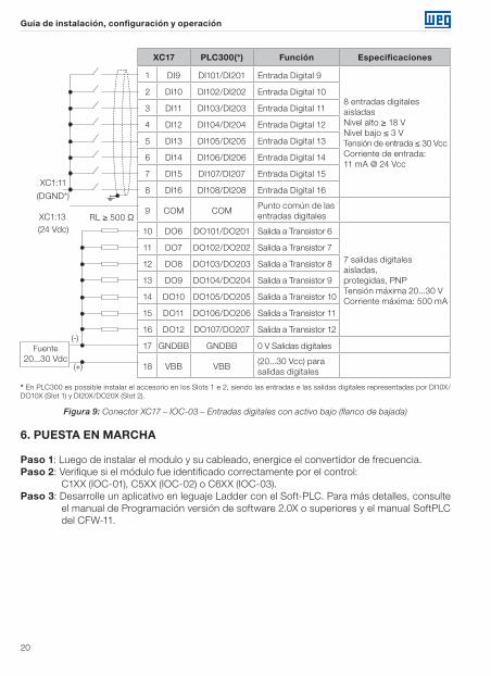
XC17 PLC300(*) Función Especificaciones
1 DI9 DI101/DI201 Entrada Digital 9
8 entradas digitales aisladasNivel alto ≥ 18 V Nivel bajo ≤ 3 VTensión de entrada ≤ 30 VccCorriente de entrada: 11 mA @ 24 Vcc
2 DI10 DI102/DI202 Entrada Digital 10
3 DI11 DI103/DI203 Entrada Digital 11
4 DI12 DI104/DI204 Entrada Digital 12
5 DI13 DI105/DI205 Entrada Digital 13
6 DI14 DI106/DI206 Entrada Digital 14
7 DI15 DI107/DI207 Entrada Digital 15
8 DI16 DI108/DI208 Entrada Digital 16
9 COM COMPunto común de las entradas digitales
10 DO6 DO101/DO201 Salida a Transistor 6
7 salidas digitales aisladas,protegidas, PNPTensión máxima 20...30 VCorriente máxima: 500 mA
11 DO7 DO102/DO202 Salida a Transistor 7
12 DO8 DO103/DO203 Salida a Transistor 8
13 DO9 DO104/DO204 Salida a Transistor 9
14 DO10 DO105/DO205 Salida a Transistor 10
15 DO11 DO106/DO206 Salida a Transistor 11
16 DO12 DO107/DO207 Salida a Transistor 12
17 GNDBB GNDBB 0 V Salidas digitales
18 VBB VBB(20...30 Vcc) para salidas digitales
RL ≥ 500 Ω
XC1:11
(DGND*)
XC1:13(24 Vdc)
Fuente 20...30 Vdc
(-)
(+)
* En PLC300 es possible instalar el accesorio en los Slots 1 e 2, siendo las entradas e las salidas digitales representadas por DI10X/DO10X (Slot 1) y DI20X/DO20X (Slot 2).
Figura 9: Conector XC17 – IOC-03 – Entradas digitales con activo bajo (flanco de bajada)
6. PUESTA EN MARCHA
Paso 1: Luego de instalar el modulo y su cableado, energice el convertidor de frecuencia.Paso 2: Verifique si el módulo fue identificado correctamente por el control:
C1XX (IOC-01), C5XX (IOC-02) o C6XX (IOC-03).Paso 3: Desarrolle un aplicativo en leguaje Ladder con el Soft-PLC. Para más detalles, consulte
el manual de Programación versión de software 2.0X o superiores y el manual SoftPLC del CFW-11.
Guia de instalação, configuração e operação
21
1. INFORMAÇÕES DE SEGURANÇA
Todos os procedimentos de segurança descritos no manual devem ser seguidos.
2. INFORMAÇÕES GERAIS
Este guia orienta a instalação, configuração e operação dos módulos opcionais IOC-01, IOC-02 e IOC-03. Estes módulos são dedicados à expansão de entradas e saídas digitais em aplicativos do soft-PLC.
NOTA!Os acessórios IOC-01 e IOC-02 somente podem ser usados em inversores CFW-11 com versão de software V2.00 ou superior. O acessório IOC-03 somente pode ser usado em inversores CFW-11 com versão de software V3.10 ou superior.
3. CONTEÚDO DA EMBALAGEM
� Módulo de acessório em embalagem anti-estática. � Guia de instalação, configuração e operação. � Parafuso de fixação.
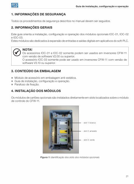
4. INSTALAÇÃO DOS MÓDULOS
Os módulos de cartões opcionais são instalados diretamente em slots localizados sobre o módulo de controle do CFW-11.
- slot 1: branco
- slot 2: amarelo
- slot 3: verde
Figura 1: Identificação dos slots dos módulos opcionais
Guia de instalação, configuração e operação
22
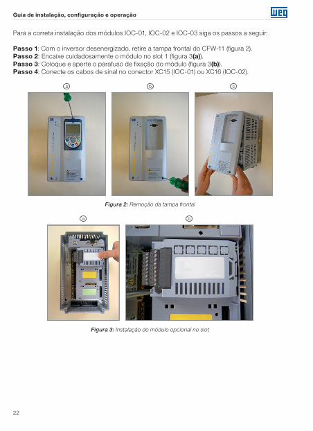
Para a correta instalação dos módulos IOC-01, IOC-02 e IOC-03 siga os passos a seguir:
Passo 1: Com o inversor desenergizado, retire a tampa frontal do CFW-11 (figura 2).Passo 2: Encaixe cuidadosamente o módulo no slot 1 (figura 3(a)).Passo 3: Coloque e aperte o parafuso de fixação do módulo (figura 3(b)).Passo 4: Conecte os cabos de sinal no conector XC15 (IOC-01) ou XC16 (IOC-02).
b ca
Figura 2: Remoção da tampa frontal
ba
Figura 3: Instalação do módulo opcional no slot
Guia de instalação, configuração e operação
23
5. ESPECIFICAÇÕES TÉCNICAS
5.1 CONEXÕES E INDICAÇÕES
XC15 PLC300(*) Função Especificações
1 DI9 DI101/DI201 Entrada Digital 9
8 entradas digitais isoladasNível alto ≥ 18 V Nível baixo ≤ 3 VTensão de entrada ≤ 30 VCorrente de entrada: 11 mA @ 24 Vcc
2 DI10 DI102/DI202 Entrada Digital 10
3 DI11 DI103/DI203 Entrada Digital 11
4 DI12 DI104/DI204 Entrada Digital 12
5 DI13 DI105/DI205 Entrada Digital 13
6 DI14 DI106/DI206 Entrada Digital 14
7 DI15 DI107/DI207 Entrada Digital 15
8 DI16 DI108/DI208 Entrada Digital 16
9 COM COMPonto comum das entradas digitais
10 NA6 NA101/NA201Saída digital 6 DO6 (RL6)
Capacidade dos contatos:Tensão máxima: 240 VcaCorrente máxima:1 ANA – Contato normalmente abertoC - Comum
11 C6 C101/C201
12 NA7 NA102/NA202Saída digital 7 DO7 (RL7)
13 C7 C102/C202
14 NA8 NA103/NA203Saída digital 8 DO8 (RL8)
15 C8 C103/C203
16 NA9 NA104/NA204Saída digital 9 DO9 (RL9)
17 C9 C104/C204
18 NC NC
Controle CC11
XC1:
13(2
4 V
CC
)
XC1:
11(D
GN
D*)
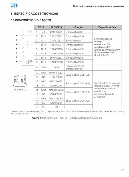
* No PLC300 é possível instalar o acessório nos Slots 1 e 2, sendo as entradas e saídas digitais representadas por DI10X/DO10X (Slot 1) e DI20X/DO20X (Slot 2).
Figura 4: Conector XC15 – IOC-01 – Entradas digitais como ativo alto
Guia de instalação, configuração e operação
24
XC15 PLC300(*) Função Especificações
1 DI9 DI101/DI201 Entrada Digital 9
8 entradas digitais isoladasNível alto ≥ 18 V Nível baixo ≤ 3 VTensão de entrada ≤ 30 VCorrente de entrada: 11 mA @ 24 Vcc
2 DI10 DI102/DI202 Entrada Digital 10
3 DI11 DI103/DI203 Entrada Digital 11
4 DI12 DI104/DI204 Entrada Digital 12
5 DI13 DI105/DI205 Entrada Digital 13
6 DI14 DI106/DI206 Entrada Digital 14
7 DI15 DI107/DI207 Entrada Digital 15
8 DI16 DI108/DI208 Entrada Digital 16
9 COM COMPonto comum das entradas digitais
10 NA6 NA101/NA201Saída digital 6 DO6 (RL6)
Capacidade dos contatos:Tensão máxima: 240 VcaCorrente máxima:1 ANA – Contato normalmente abertoC - Comum
11 C6 C101/C201
12 NA7 NA102/NA202Saída digital 7 DO7 (RL7)
13 C7 C102/C202
14 NA8 NA103/NA203Saída digital 8 DO8 (RL8)
15 C8 C103/C203
16 NA9 NA104/NA204Saída digital 9 DO9 (RL9)
17 C9 C104/C204
18 NC NC
Controle CC11
XC1:
11(D
GN
D*)
XC1:
13(2
4 V
CC
)
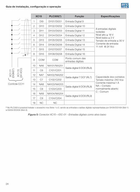
* No PLC300 é possível instalar o acessório nos Slots 1 e 2, sendo as entradas e saídas digitais representadas por DI10X/DO10X (Slot 1) e DI20X/DO20X (Slot 2).
Figura 5: Conector XC15 – IOC-01 - Entradas digitais como ativo baixo
Guia de instalação, configuração e operação
25
XC16 PLC300(*) Função Especificações
1 DI9 DI101/DI201 Entrada Digital 9
8 entradas digitais isoladasNível alto ≥ 18 V Nível baixo ≤ 3 VTensão de entrada ≤ 30 VCorrente de entrada: 11 mA @ 24 Vcc
2 DI10 DI102/DI202 Entrada Digital 10
3 DI11 DI103/DI203 Entrada Digital 11
4 DI12 DI104/DI204 Entrada Digital 12
5 DI13 DI105/DI205 Entrada Digital 13
6 DI14 DI106/DI206 Entrada Digital 14
7 DI15 DI107/DI207 Entrada Digital 15
8 DI16 DI108/DI208 Entrada Digital 16
9 COM COMPonto comum das entradas digitais
10 DO6 DO101/DO201 Saída a Transistor 6
8 saídas digitais isoladas,Coletor aberto com diodo de roda livreTensão máxima: 24 VCorrente máxima: 50 mA
11 DO7 DO102/DO202 Saída a Transistor 7
12 DO8 DO103/DO203 Saída a Transistor 8
13 DO9 DO104/DO204 Saída a Transistor 9
14 DO10 DO105/DO205 Saída a Transistor 10
15 DO11 DO106/DO206 Saída a Transistor 11
16 DO12 DO107/DO207 Saída a Transistor 12
17 DO13 DO108/DO208 Saída a Transistor 13
18 24 Vcc 24 Vcc Fonte 24 VccFonte de alimentação24 Vcc ± 8 %Capacidade: 500 mA
XC1:13
XC1:11RL ≥ 500 Ω
(24 VCC)
(DGND*)
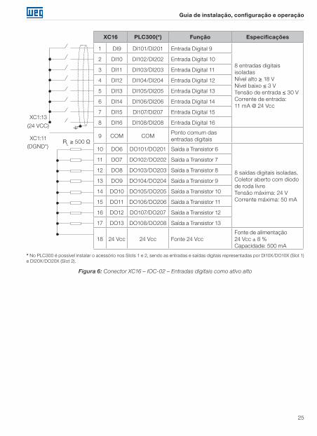
* No PLC300 é possível instalar o acessório nos Slots 1 e 2, sendo as entradas e saídas digitais representadas por DI10X/DO10X (Slot 1) e DI20X/DO20X (Slot 2).
Figura 6: Conector XC16 – IOC-02 – Entradas digitais como ativo alto
Guia de instalação, configuração e operação
26
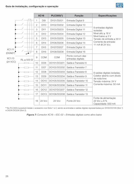
XC16 PLC300(*) Função Especificações
1 DI9 DI101/DI201 Entrada Digital 9
8 entradas digitais isoladasNível alto ≥ 18 V Nível baixo ≤ 3 VTensão de entrada ≤ 30 VCorrente de entrada: 11 mA @ 24 Vcc
2 DI10 DI102/DI202 Entrada Digital 10
3 DI11 DI103/DI203 Entrada Digital 11
4 DI12 DI104/DI204 Entrada Digital 12
5 DI13 DI105/DI205 Entrada Digital 13
6 DI14 DI106/DI206 Entrada Digital 14
7 DI15 DI107/DI207 Entrada Digital 15
8 DI16 DI108/DI208 Entrada Digital 16
9 COM COMPonto comum das entradas digitais
10 DO6 DO101/DO201 Saída a Transistor 6
8 saídas digitais isoladas,Coletor aberto com diodo de roda livreTensão máxima: 24 VCorrente máxima: 50 mA
11 DO7 DO102/DO202 Saída a Transistor 7
12 DO8 DO103/DO203 Saída a Transistor 8
13 DO9 DO104/DO204 Saída a Transistor 9
14 DO10 DO105/DO205 Saída a Transistor 10
15 DO11 DO106/DO206 Saída a Transistor 11
16 DO12 DO107/DO207 Saída a Transistor 12
17 DO13 DO108/DO208 Saída a Transistor 13
18 24 Vcc 24 Vcc Fonte 24 VccFonte de alimentação24 Vcc ± 8 %Capacidade: 500 mA
XC1:11
XC1:13RL ≥ 500 Ω
(DGND*)
(24 VCC)
* No PLC300 é possível instalar o acessório nos Slots 1 e 2, sendo as entradas e saídas digitais representadas por DI10X/DO10X (Slot 1) e DI20X/DO20X (Slot 2).
Figura 7: Conector XC16 – IOC-02 – Entradas digitais como ativo baixo
Guia de instalação, configuração e operação
27
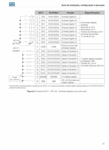
XC17 PLC300(*) Função Especificações
1 DI9 DI101/DI201 Entrada Digital 9
8 entradas digitais isoladasNível alto ≥ 18 V Nível baixo ≤ 3 VTensão de entrada ≤ 30 VCorrente de entrada: 11 mA @ 24 Vcc
2 DI10 DI102/DI202 Entrada Digital 10
3 DI11 DI103/DI203 Entrada Digital 11
4 DI12 DI104/DI204 Entrada Digital 12
5 DI13 DI105/DI205 Entrada Digital 13
6 DI14 DI106/DI206 Entrada Digital 14
7 DI15 DI107/DI207 Entrada Digital 15
8 DI16 DI108/DI208 Entrada Digital 16
9 COM COMPonto comum das entradas digitais
10 DO6 DO101/DO201 Saída a Transistor 6
7 saídas digitais isoladas,protegidas, PNPTensão (20...30 V)Corrente máxima: 500 mA
11 DO7 DO102/DO202 Saída a Transistor 7
12 DO8 DO103/DO203 Saída a Transistor 8
13 DO9 DO104/DO204 Saída a Transistor 9
14 DO10 DO105/DO205 Saída a Transistor 10
15 DO11 DO106/DO206 Saída a Transistor 11
16 DO12 DO107/DO207 Saída a Transistor 12
17 GNDBB GNDBB 0 V Saídas digitais
18 VBB VBB(20...30 Vcc) para as saídas digitais
XC1:13
(24 VCC)
XC1:11(DGND*)
Fonte 20...30 Vcc
(-)
(+)
* No PLC300 é possível instalar o acessório nos Slots 1 e 2, sendo as entradas e saídas digitais representadas por DI10X/DO10X (Slot 1) e DI20X/DO20X (Slot 2).
Figura 8: Conector XC17 – IOC-03 – Entradas digitais como ativo alto
Guia de instalação, configuração e operação
28
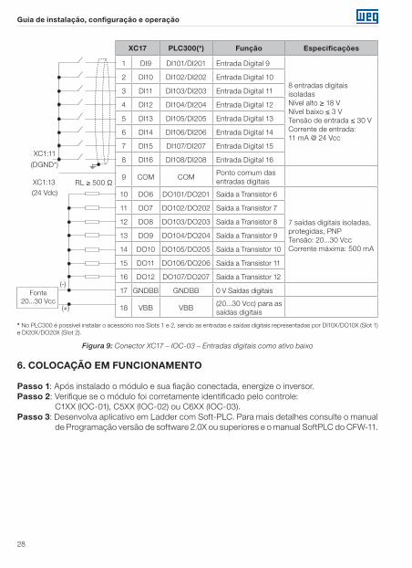
XC17 PLC300(*) Função Especificações
1 DI9 DI101/DI201 Entrada Digital 9
8 entradas digitais isoladasNível alto ≥ 18 V Nível baixo ≤ 3 VTensão de entrada ≤ 30 VCorrente de entrada: 11 mA @ 24 Vcc
2 DI10 DI102/DI202 Entrada Digital 10
3 DI11 DI103/DI203 Entrada Digital 11
4 DI12 DI104/DI204 Entrada Digital 12
5 DI13 DI105/DI205 Entrada Digital 13
6 DI14 DI106/DI206 Entrada Digital 14
7 DI15 DI107/DI207 Entrada Digital 15
8 DI16 DI108/DI208 Entrada Digital 16
9 COM COMPonto comum das entradas digitais
10 DO6 DO101/DO201 Saída a Transistor 6
7 saídas digitais isoladas,protegidas, PNPTensão: 20...30 VccCorrente máxima: 500 mA
11 DO7 DO102/DO202 Saída a Transistor 7
12 DO8 DO103/DO203 Saída a Transistor 8
13 DO9 DO104/DO204 Saída a Transistor 9
14 DO10 DO105/DO205 Saída a Transistor 10
15 DO11 DO106/DO206 Saída a Transistor 11
16 DO12 DO107/DO207 Saída a Transistor 12
17 GNDBB GNDBB 0 V Saídas digitais
18 VBB VBB(20...30 Vcc) para as saídas digitais
RL ≥ 500 Ω
XC1:11
(DGND*)
XC1:13(24 Vdc)
Fonte 20...30 Vcc
(-)
(+)
* No PLC300 é possível instalar o acessório nos Slots 1 e 2, sendo as entradas e saídas digitais representadas por DI10X/DO10X (Slot 1) e DI20X/DO20X (Slot 2).
Figura 9: Conector XC17 – IOC-03 – Entradas digitais como ativo baixo
6. COLOCAÇÃO EM FUNCIONAMENTO
Passo 1: Após instalado o módulo e sua fiação conectada, energize o inversor.Passo 2: Verifique se o módulo foi corretamente identificado pelo controle:
C1XX (IOC-01), C5XX (IOC-02) ou C6XX (IOC-03).Passo 3: Desenvolva aplicativo em Ladder com Soft-PLC. Para mais detalhes consulte o manual
de Programação versão de software 2.0X ou superiores e o manual SoftPLC do CFW-11.


WEG Equipamentos Elétricos S.A. Jaraguá do Sul - SC - Brazil Phone 55 (47) 3276-4000 - Fax 55 (47) 3276-4020São Paulo - SP - Brazil Phone 55 (11) 5053-2300 - Fax 55 (11) [email protected] D
ocum
ent:
100
006
7584
2 /
02