Embed Size (px)
DESCRIPTION
Generic Requirements for Printed Board Assembly Products Manufacturing Description Data and Transfer Technology
Citation preview

IPC-2581with Amendment 1
Generic Requirements
for Printed Board Assembly
Products Manufacturing
Description Data and
Transfer Methodology
ASSOCIATION CONNECTINGELECTRONICS INDUSTRIES
3000 Lakeside Drive, Suite 309S, Bannockburn, IL 60015-1249Tel. 847.615.7100 Fax 847.615.7105
www.ipc.org
IPC-2581with Amendment 1May 2007 A standard developed by IPC
Supersedes IPC-2581March 2004
Endorsed by the InternationalElectronics ManuafacturingInitiative (iNEMI)
The Principles ofStandardization
In May 1995 the IPC’s Technical Activities Executive Committee (TAEC) adopted Principles ofStandardization as a guiding principle of IPC’s standardization efforts.
Standards Should:• Show relationship to Design for Manufacturability
(DFM) and Design for the Environment (DFE)• Minimize time to market• Contain simple (simplified) language• Just include spec information• Focus on end product performance• Include a feedback system on use and
problems for future improvement
Standards Should Not:• Inhibit innovation• Increase time-to-market• Keep people out• Increase cycle time• Tell you how to make something• Contain anything that cannot
be defended with data
Notice IPC Standards and Publications are designed to serve the public interest through eliminating mis-understandings between manufacturers and purchasers, facilitating interchangeability and improve-ment of products, and assisting the purchaser in selecting and obtaining with minimum delay theproper product for his particular need. Existence of such Standards and Publications shall not inany respect preclude any member or nonmember of IPC from manufacturing or selling productsnot conforming to such Standards and Publication, nor shall the existence of such Standards andPublications preclude their voluntary use by those other than IPC members, whether the standardis to be used either domestically or internationally.
Recommended Standards and Publications are adopted by IPC without regard to whether their adop-tion may involve patents on articles, materials, or processes. By such action, IPC does not assumeany liability to any patent owner, nor do they assume any obligation whatever to parties adoptingthe Recommended Standard or Publication. Users are also wholly responsible for protecting them-selves against all claims of liabilities for patent infringement.
IPC PositionStatement onSpecificationRevision Change
It is the position of IPC’s Technical Activities Executive Committee that the use and implementationof IPC publications is voluntary and is part of a relationship entered into by customer and supplier.When an IPC publication is updated and a new revision is published, it is the opinion of the TAECthat the use of the new revision as part of an existing relationship is not automatic unless requiredby the contract. The TAEC recommends the use of the latest revision. Adopted October 6, 1998
Why is therea charge forthis document?
Your purchase of this document contributes to the ongoing development of new and updated indus-try standards and publications. Standards allow manufacturers, customers, and suppliers to under-stand one another better. Standards allow manufacturers greater efficiencies when they can setup their processes to meet industry standards, allowing them to offer their customers lower costs.
IPC spends hundreds of thousands of dollars annually to support IPC’s volunteers in the standardsand publications development process. There are many rounds of drafts sent out for review andthe committees spend hundreds of hours in review and development. IPC’s staff attends and par-ticipates in committee activities, typesets and circulates document drafts, and follows all necessaryprocedures to qualify for ANSI approval.
IPC’s membership dues have been kept low to allow as many companies as possible to participate.Therefore, the standards and publications revenue is necessary to complement dues revenue. Theprice schedule offers a 50% discount to IPC members. If your company buys IPC standards andpublications, why not take advantage of this and the many other benefits of IPC membership aswell? For more information on membership in IPC, please visit www.ipc.org or call 847/597-2872.
Thank you for your continued support.
©Copyright 2007. IPC, Bannockburn, Illinois. All rights reserved under both international and Pan-American copyright conventions. Any copying,scanning or other reproduction of these materials without the prior written consent of the copyright holder is strictly prohibited and constitutesinfringement under the Copyright Law of the United States.

IPC-2581with Amendment 1
Generic Requirements for
Printed Board Assembly
Products Manufacturing
Description Data and
Transfer Methodology
Developed by the CAD/CAM Convergence Subcommittee (2-17) of theData Generation and Transfer Committee (2-10) of IPC
Users of this publication are encouraged to participate in thedevelopment of future revisions.Contact:
IPC3000 Lakeside Drive, Suite 309SBannockburn, Illinois60015-1249Tel 847 615.7100Fax 847 615.7105
Supersedes:IPC-2581 - March 2004
ASSOCIATION CONNECTINGELECTRONICS INDUSTRIES
AcknowledgmentAny document involving a complex technology draws material from a vast number of sources. While the principal membersof the CAD/CAM Convergence Subcommittee (2-17) of the Data Generation and Transfer Committee (2-10) are shownbelow, it is not possible to include all of those who assisted in the evolution of this standard. To each of them, the mem-bers of the IPC extend their gratitude.
Data Generation andTransfer Committee
CAD/CAM ConvergenceSubcommittee
Technical Liaisons of theIPC Board of Directors
ChairKaren McConnellLockheed Martin
Co-ChairsDan SmithMentor Graphics
Karen McConnellLockheed Martin
Nilesh S. NaikEagle Circuits Inc.
Sammy YiFlextronics International
CAD/CAM Convergence Subcommittee
Kjell Asp, Ericsson AB
Paul Barrow, Valor ComputerizedSystems
Gary Carter, Fujitsu NetworkCommunications
Chris Czernel, Router Solutions
Art Griesser, National Institute ofStandards & Technology (NIST)
Ed Hickey, Cadence Design Systems
Tero Karkkainen, Nokia
Dana Korf, Sanmina-SCI Corporation
Göran Lundqvist, Ericsson AB
Karen McConnell, Lockheed Martin
John Minchella, CelesticaInternational
Norwood Sisson
Daniel Smith, Mentor GraphicsCorporation
Louis Watson, Nacom Corporation
IPC-2581 with Amendment 1 May 2007
ii
TABLE OF CONTENTS
1 SCOPE .................................................................................................................................... 1 1.1 Focus and intent ............................................................................................................ 1 1.2 Notation ......................................................................................................................... 1
2 APPLICABLE DOCUMENTS ................................................................................................... 2 2.1 Documentation conventions ........................................................................................... 2
3 REQUIREMENTS .................................................................................................................... 4 3.1 Rules concerning the use of XML and XML Schema ..................................................... 5
3.1.1 File readability and uniformity............................................................................ 6 3.1.2 File markers....................................................................................................... 6 3.1.3 File extension .................................................................................................... 6 3.1.4 File remarks....................................................................................................... 6 3.1.5 Character set definition ..................................................................................... 6
3.2 Data organization and identification rules ...................................................................... 6 3.2.1 Naming elements within a 258X file................................................................... 6 3.2.2 The use of XML elements and types ................................................................. 7 3.2.3 Attribute base types (governing templates) ....................................................... 7 3.2.4 Coordinate system and transformation rules ..................................................... 9
3.3 Transformation characteristics (Xform) ........................................................................ 10 3.3.1 The x and y Offset attributes ........................................................................... 11 3.3.2 The rotation attribute ....................................................................................... 11 3.3.3 The mirror attribute.......................................................................................... 11 3.3.4 The scale attribute ........................................................................................... 12 3.3.5 The x and y Location attributes ....................................................................... 12
3.4 Substitution groups ...................................................................................................... 12 3.4.1 Attribute........................................................................................................... 14 3.4.2 ColorGroup...................................................................................................... 17 3.4.3 Feature ............................................................................................................ 18 3.4.4 Fiducial ............................................................................................................ 18 3.4.5 FirmwareGroup................................................................................................ 19 3.4.6 FontDef............................................................................................................ 19 3.4.7 LineDescGroup................................................................................................ 19 3.4.8 PolyStep .......................................................................................................... 20 3.4.9 Simple ............................................................................................................. 20 3.4.10 StandardPrimitive ............................................................................................ 21 3.4.11 StandardShape................................................................................................ 23 3.4.12 UserPrimitive ................................................................................................... 23 3.4.13 UserShape ...................................................................................................... 24
4 CONTENT ............................................................................................................................. 25 4.1 Content: FunctionMode............................................................................................... 26
4.1.1 FULL mode...................................................................................................... 27 4.1.2 DESIGN mode................................................................................................. 27
iii
4.1.3 FABRICATION mode....................................................................................... 27 4.1.4 ASSEMBLY mode ........................................................................................... 27 4.1.5 TEST mode ..................................................................................................... 27
4.2 Function levels ............................................................................................................. 27 4.2.1 FULL Mode Level 1 ......................................................................................... 28 4.2.2 Design Levels .................................................................................................. 29 4.2.3 Fabrication Levels ........................................................................................... 31 4.2.4 Assembly Levels.............................................................................................. 33 4.2.5 Test Levels ...................................................................................................... 36
4.3 Content: StepRef ......................................................................................................... 37 4.4 Content: LayerRef ........................................................................................................ 38 4.5 Content: BomRef.......................................................................................................... 38 4.6 Content: AvlRef............................................................................................................ 39 4.7 Content: DictionaryStandard ........................................................................................ 39
4.7.1 StandardPrimitive: Butterfly ............................................................................. 40 4.7.2 StandardPrimitive: Circle ................................................................................. 41 4.7.3 StandardPrimitive: Contour ............................................................................. 41 4.7.4 StandardPrimitive: Diamond ............................................................................ 43 4.7.5 StandardPrimitive: Donut................................................................................. 44 4.7.6 StandardPrimitive: Ellipse................................................................................ 46 4.7.7 StandardPrimitive: Hexagon ............................................................................ 46 4.7.8 StandardPrimitive: Moire ................................................................................. 47 4.7.9 StandardPrimitive: Octagon............................................................................. 48 4.7.10 StandardPrimitive: Oval ................................................................................... 49 4.7.11 StandardPrimitive: RectCenter ........................................................................ 49 4.7.12 StandardPrimitive: RectCham ......................................................................... 50 4.7.13 StandardPrimitive: RectCorner ........................................................................ 51 4.7.14 StandardPrimitive: RectRound ........................................................................ 52 4.7.15 StandardPrimitive: Thermal ............................................................................. 53 4.7.16 StandardPrimitive: Triangle ............................................................................. 56
4.8 Content: DictionaryUser ............................................................................................... 57 4.8.1 UserPrimitive, Simple ...................................................................................... 57 4.8.2 UserPrimitive: Text .......................................................................................... 62 4.8.3 UserPrimitive: UserSpecial .............................................................................. 64
4.9 Content: DictionaryFont ............................................................................................... 65 4.9.1 FontDefEmbedded........................................................................................... 66 4.9.2 FontDefExternal .............................................................................................. 66 4.9.3 FontDef: Glyph ................................................................................................ 66 4.9.4 FontDef: Glyph combination ............................................................................ 67
4.10 Content: DictionaryLineDesc........................................................................................ 68 4.10.1 LineDesc ......................................................................................................... 69 4.10.2 LineDescRef .................................................................................................... 69
4.11 Content: DictionaryColor .............................................................................................. 69 4.11.1 Color................................................................................................................ 70
iv

4.11.2 ColorRef .......................................................................................................... 71 4.12 Content: DictionaryFirmware........................................................................................ 71
4.12.1 CachedFirmware ............................................................................................. 71 4.12.2 FirmwareRef .................................................................................................... 72
5 LOGISTIC HEADER .............................................................................................................. 72 5.1 LogisticHeader ............................................................................................................. 72 5.2 Role ............................................................................................................................. 74 5.3 Enterprise .................................................................................................................... 75 5.4 Person ......................................................................................................................... 76
6 HISTORY RECORD............................................................................................................... 77 6.1 HistoryRecord .............................................................................................................. 77 6.2 FileRevision ................................................................................................................. 78 6.3 SoftwarePackage ......................................................................................................... 78 6.4 ChangeRec .................................................................................................................. 79
7 BOM (Material List)................................................................................................................ 80 7.1 BOM Header ................................................................................................................ 81 7.2 BomItem....................................................................................................................... 82
7.2.1 RefDes ............................................................................................................ 83 7.2.2 Characteristics................................................................................................. 84
8 ELECTRONIC COMPUTER AIDED DESIGN (ECAD) ........................................................... 87 8.1 CadHeader................................................................................................................... 88
8.1.1 Spec ................................................................................................................ 88 8.1.2 SurfaceFinish .................................................................................................. 90 8.1.3 ChangeRec...................................................................................................... 91
8.2 CadData....................................................................................................................... 91 8.2.1 Layer ............................................................................................................... 92 8.2.2 Stackup ........................................................................................................... 99 8.2.3 Step............................................................................................................... 103 8.2.4 DfxMeasurementList...................................................................................... 147
9 APPROVED VENDOR LIST (AVL) ...................................................................................... 149 9.1 AvlHeader .................................................................................................................. 149 9.2 AvlItem....................................................................................................................... 150
9.2.1 AvlVmpn ........................................................................................................ 151 10 GLOSSARY ......................................................................................................................... 153
10.1 Process flow Descriptions .......................................................................................... 153 10.2 Terms and Definitions ................................................................................................ 154 10.3 Enumerated strings of 2581 ....................................................................................... 155
11 REFERENCE INFORMATION ............................................................................................. 155 11.1 IPC (1) ....................................................................................................................... 155 11.2 American National Standards Institute (2).................................................................. 155 11.3 Department of Defense (3)......................................................................................... 156 11.4 Electronic Industries Association (4) .......................................................................... 156 11.5 International Organization for Standards (ISO) .......................................................... 156
v

Appendix A IPC-7351 Naming Convention for Land Patterns..................................................... 157 Appendix B Panel Instance File.................................................................................................. 162
vi
IPC-2581 includes Amendment 1 May 2007
Generic Requirements for Printed Board Assembly Products Manufacturing Description Data and Transfer Methodology
1 SCOPE
This standard specifies the XML schema that represents the intelligent data file format used to describe printed board and printed board assembly products with details sufficient for tooling, manufacturing, assembly, and inspection requirements. This format may be used for transmitting information between a printed board designer and a manufacturing or assembly facility. The data is most useful when the manufacturing cycle includes computer-aided processes and numerical control machines.
The data can be defined in either English or International System of Units (SI) units. The format is a convergence of the IPC-2511 “GenCAM” and the Valor Computerized Systems “ODB-X” format structure.
1.1 Focus and intent The generic format requirements are provided in a series of standards focused on printed board manufacturing, assembly, and inspection testing. This standard series consists of a generic standard (IPC-2581) that contains all the general requirements. There are seven sectional standards that are focused on the XML details necessary to accumulate information in the single file, that addresses the needs of the manufacturing disciplines producing a particular product.
The sectional standards (IPC-2582 through 2588) paraphrase the important requirements and provide suggested usage and examples for the topic covered by the sectional standard.
1.2 Notation Although the data would be contained in a single file, the file can have different purposes as described in Section 4. The XML schema used for this standard follows the notations set forth by the W3C and is as follows:
element – Element appears exactly one time element? – Element may appear 0 or 1 times element* – Element may appear 0 or more times element+ – Element may appear 1 or more times
Any IPC-258X file is composed of a high level element (IPC-2581) that contains up to six sub-elements:
Content – information about the contents of the 258X file LogisticHeader – information pertaining to the order and supply data HistoryRec – change information of the file Bom – Bill of Materials (Material List) information Ecad – Computer Aided Design (engineering) information Avl – Approved Vendors List information
1
IPC-2581 includes Amendment 1 May 2007
2 APPLICABLE DOCUMENTS
The following documents contain requirements which, when referenced, constitutes provisions of IPC-2581. At the time of publication, the editions indicated were valid. All documents are subject to revision and parties entering into agreements based on this standard are encouraged to investigate the possibility of applying the most recent editions of the documents indicated below.
The revision of the document in effect at the time of solicitation shall take precedence.
IPC-T-50 Terms and Definitions for Interconnecting and Packaging Electronic Circuits
IPC-2501 Definition for Web-Based Exchange of XML Data
IPC-2524 PWB Fabrication Data Quality Rating System
IPC-2511 Generic Requirements for Implementation of Product Manufacturing Description Data and Transfer XML Schema Methodology
IPC-2571 Generic Requirements for Electronics Manufacturing Supply Chain Communication - Product Data eXchange (PDX)
IPC-2576 Sectional Requirements for Electronics Manufacturing Supply Chain Communication of As-Built Product Data - Product Data eXchange
IPC-2577 Sectional Requirements for Supply Chain Communication of Manufacturing Quality Assessment - Product Data eXchange (PDX)
IPC-2578 Sectional Requirements for Supply Chain Communication of Bill of Material and Product Design Configuration Data - Product Data eXchange
IPC-7351 Generic Requirements for Surface Mount Design and Land Patterns 2.1 Documentation conventions The XML file format standard and the XML Schema definition language standard, as defined the by World Wide Web Consortium (W3C), have been adopted by IPC for use in the IPC-2500 series of standards.
In addition to the text based schema notation this document provides graphical representation of the structure of the file format. The XML diagrams are designed to effectively illustrate the structure and cardinality of elements and attributes that make up any IPC-258X file. The notation in the graphics does not provide a complete visualization of the schema definition for the file format, but it does provide a good top down overview. Should there be any conflict between the graphical notation and the schema notation, the authoritative definition is the schema notation.
Table 1 provides an overview of the graphical notation used in the document.
2
IPC-2581 includes Amendment 1 May 2007
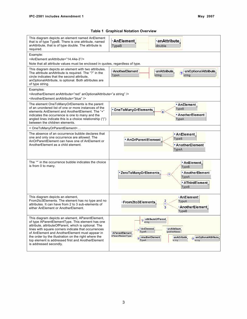
Table 1 Graphical Notation Overview
This diagram depicts an element named AnElement that is of type TypeB. There is one attribute, named anAttribute, that is of type double. The attribute is required.
Example: <AnElement anAttribute=”14.44e-3”/> Note that all attribute values must be enclosed in quotes, regardless of type.
This diagram depicts an element with two attributes. The attribute anAttribute is required. The “?” in the circle indicates that the second attribute, anOptionalAttribute, is optional. Both attributes are of type string.
Examples: <AnotherElement anAttribute=”red” anOptionalAttribute=”a string” /> <AnotherElement anAttribute=”blue” />
The element OneToManyOrElements is the parent of an unordered list of one or more instances of the elements AnElement and AnothertElement. The “+” indicates the occurrence is one to many and the angled lines indicate this is a choice relationship (“|”) between the children elements.
< OneToManyOrParentElement>…
The absence of an occurrence bubble declares that one and only one occurrence are allowed. The AnOrParentElement can have one of AnElement or AnotherElement as a child element.
The ‘*’ in the occurrence bubble indicates the choice is from 0 to many.
This diagram depicts an element, From2to3Elements. The element has no type and no attributes. It can have from 2 to 3 sub-elements of either AnElement or AnotherElement.
This diagram depicts an element, AParentElement, of type AParentElementType. This element has one attribute, attributeOfParent, which is optional. The lines with square corners indicate that occurrences of AnElement and AnotherElement must appear in the order by the illustration on the right where the top element is addressed first and AnotherElement is addressed secondly.
3
IPC-2581 includes Amendment 1 May 2007
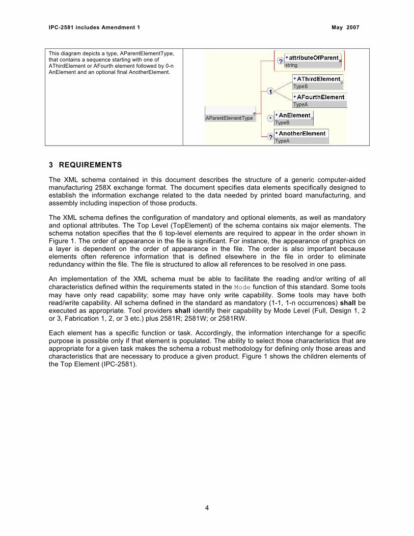
This diagram depicts a type, AParentElementType, that contains a sequence starting with one of AThirdElement or AFourth element followed by 0-n AnElement and an optional final AnotherElement.
3 REQUIREMENTS
The XML schema contained in this document describes the structure of a generic computer-aided manufacturing 258X exchange format. The document specifies data elements specifically designed to establish the information exchange related to the data needed by printed board manufacturing, and assembly including inspection of those products.
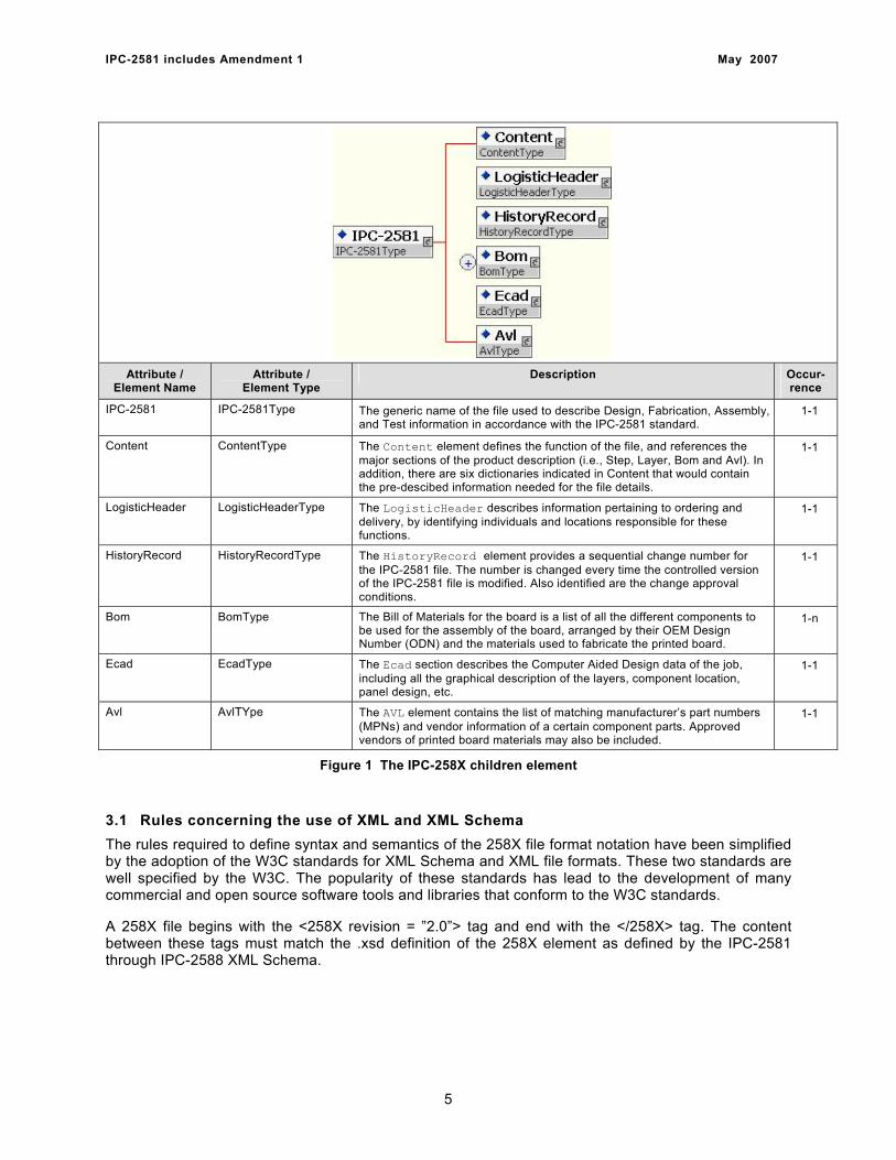
The XML schema defines the configuration of mandatory and optional elements, as well as mandatory and optional attributes. The Top Level (TopElement) of the schema contains six major elements. The schema notation specifies that the 6 top-level elements are required to appear in the order shown in Figure 1. The order of appearance in the file is significant. For instance, the appearance of graphics on a layer is dependent on the order of appearance in the file. The order is also important because elements often reference information that is defined elsewhere in the file in order to eliminate redundancy within the file. The file is structured to allow all references to be resolved in one pass.
An implementation of the XML schema must be able to facilitate the reading and/or writing of all characteristics defined within the requirements stated in the Mode function of this standard. Some tools may have only read capability; some may have only write capability. Some tools may have both read/write capability. All schema defined in the standard as mandatory (1-1, 1-n occurrences) shall be executed as appropriate. Tool providers shall identify their capability by Mode Level (Full, Design 1, 2 or 3, Fabrication 1, 2, or 3 etc.) plus 2581R; 2581W; or 2581RW.
Each element has a specific function or task. Accordingly, the information interchange for a specific purpose is possible only if that element is populated. The ability to select those characteristics that are appropriate for a given task makes the schema a robust methodology for defining only those areas and characteristics that are necessary to produce a given product. Figure 1 shows the children elements of the Top Element (IPC-2581).
4
IPC-2581 includes Amendment 1 May 2007
Attribute / Element Name
Attribute / Element Type
Description Occur-rence
IPC-2581 IPC-2581Type The generic name of the file used to describe Design, Fabrication, Assembly, and Test information in accordance with the IPC-2581 standard.
1-1
Content ContentType The Content element defines the function of the file, and references the major sections of the product description (i.e., Step, Layer, Bom and Avl). In addition, there are six dictionaries indicated in Content that would contain the pre-descibed information needed for the file details.
1-1
LogisticHeader LogisticHeaderType The LogisticHeader describes information pertaining to ordering and delivery, by identifying individuals and locations responsible for these functions.
1-1
HistoryRecord HistoryRecordType The HistoryRecord element provides a sequential change number for the IPC-2581 file. The number is changed every time the controlled version of the IPC-2581 file is modified. Also identified are the change approval conditions.
1-1
Bom BomType The Bill of Materials for the board is a list of all the different components to be used for the assembly of the board, arranged by their OEM Design Number (ODN) and the materials used to fabricate the printed board.
1-n
Ecad EcadType The Ecad section describes the Computer Aided Design data of the job, including all the graphical description of the layers, component location, panel design, etc.
1-1
Avl AvlTYpe The AVL element contains the list of matching manufacturer’s part numbers (MPNs) and vendor information of a certain component parts. Approved vendors of printed board materials may also be included.
1-1
Figure 1 The IPC-258X children element
3.1 Rules concerning the use of XML and XML Schema The rules required to define syntax and semantics of the 258X file format notation have been simplified by the adoption of the W3C standards for XML Schema and XML file formats. These two standards are well specified by the W3C. The popularity of these standards has lead to the development of many commercial and open source software tools and libraries that conform to the W3C standards.
A 258X file begins with the <258X revision = ”2.0”> tag and end with the </258X> tag. The content between these tags must match the .xsd definition of the 258X element as defined by the IPC-2581 through IPC-2588 XML Schema.
5

IPC-2581 includes Amendment 1 May 2007
3.1.1 File readability and uniformity A valid 258X file must conform to the W3C Canonical XML format. The format is defined by the http://www.w3.org/TR/xml-c14n specification. Software tools exist that will take malformed XML and automatically generate Canonical XML.
3.1.2 File markers An optional checksum can be appended following the </258X> tag. The checksum is an MD5 message digest algorithm (see Internet RFC 1321: http://www.ietf.org/rfc/rfc1321.txt) that is base64 encoded. The checksum starts with the “<” character of the <258X> tag and ending with the “>” character of the closing </258X> tag. The checksum follows immediately after the “>” character of the closing </258X> tag.
The digest provides a 128-bit checksum of the 258X file contents. The MD5 signature must be base64 encoded (see IETF RFC 1421 for the base64 algorithm) to convert the MD5 signature to a US-ASCII, base64 string. An end of line character will indicate the end of the base64 encoded MD5 signature.
3.1.3 File extension The file extension for a 258X file is .cvg.
3.1.4 File remarks The 258X format permits file remarks using the standard XML commenting notation. They are only to be used to support debugging software. A parser may ignore and discard remarks when reading a 258X file. File remarks are never to be used to represent design or manufacturing information.
3.1.5 Character set definition The XML standard uses the Unicode character set. This character set covers the characters used in hundreds of written languages. The XML standard allows several of the Unicode encoding formats to be used in an XML file. IPC-2581 through IPC-2588 requires the use of the UTF-8 character encoding of the Unicode character set. Although comments and user assigned names may be in any language of choice, all qualified names or enumerated string names shall be in English only.
3.2 Data organization and identification rules The 258X standards use a namespace mechanism for XML instance files that is similar to the XML namespace mechanism that was created for managing XML meta-data namespaces. The instance file namespace mechanism prevents collisions between the names used by the different products within a single file. This partitioning of namespaces is necessary because any of the 258X files may contain information describing an arbitrary collection of products. (Boards, assemblies, or panels that are products allowed in an IPC-258X file.) For example, a file could contain descriptions for building multiple electronic assemblies that are manufactured on separate panels. This mechanism also prepares the way for a distributed database of 258X design data in which the data can be trusted to be universally unambiguous.
3.2.1 Naming elements within a 258X file The capability of Unique namespaces was created to allow a panel to be defined in the single 258X file that contains multiple unique boards. Since two boards may reuse the same identifier, e.g. “U1”, “R1”, it must be possible to separate names in the file into namespaces. The 258X namespace implementation borrows the notation used by XML namespaces and makes the 258X standard format consistent with conventional XML usage.
There are two types of names used to name top-level objects (element instances) in a 258X file. The first type of name is a qualifiedName type. This type includes a prefix in the name that corresponds to a namespace within the 258X file. The prefix and the globally unique identity of the Namespace are declared in the Namespace element. The second type of name is a shortName type. This type is
6
IPC-2581 includes Amendment 1 May 2007
required to be unique within the 258X file. The syntax restrictions on short names and qualified names assure that all names will be unique as top-level names within 258X file.
3.2.2 The use of XML elements and types A comprehensive overview of XML Schema can be found in the W3C XML Schema Primer. This section briefly describes the decisions that were made in the development of the 258X schema. Reviewing the Primer is recommended prior to reading this section.
The XML Schema defines a namespace mechanism that can be used when defining element names. The W3C also provides a set of general purpose element and attribute types, such as xsd:string, xsd:double, and xsd:datetime. The 258X format uses these standard types, however the documentation of the 258X standard has been defined without the use of a namespace prefix for element names within a 258X file.
Each of the schema elements has a prefix, “xsd:”, which is associated with the XML Schema namespace through the declaration, xmlns:xsd=”http://www.w3.org/2000/08/XMLSchema”, that appears in the schema element. The prefix xsd: is used by convention to denote the XML Schema namespace, although any prefix can be used. The same prefix, and hence the same association, also appears on the names of built-in simple types, e.g. xsd:string. The purpose of the association is to identify the elements and simple types as belonging to the vocabulary of the XML Schema language rather than the vocabulary of the schema author.
In XML Schema, there is a basic difference between complex types that allow elements in their content and may carry attributes, and simple types that cannot have element content and cannot carry attributes. There is also a major distinction between definitions that create new types (both simple and complex), and declarations that enable elements and attributes with specific names and types (both simple and complex) to appear in document instances.
New complex types are defined using the complexType element and such definitions typically contain a set of element declarations, element references, and attribute declarations. The declarations are not themselves types, but rather an association between a name and constraints that govern the appearance of that name in documents governed by the associated schema. Elements are declared using the “element,” and attributes are declared using the “attribute.”
3.2.3 Attribute base types (governing templates) The attribute basic types (SimpleTypes) provided by XML Schema are defined by the W3C. They are easy to distinguish from the IPC-258X types because the W3C type is always prefixed with “xsd:”. The W3C datatypes are defined in http://www.w3.org/2000/10/XMLSchema (XML Schema Part 2).
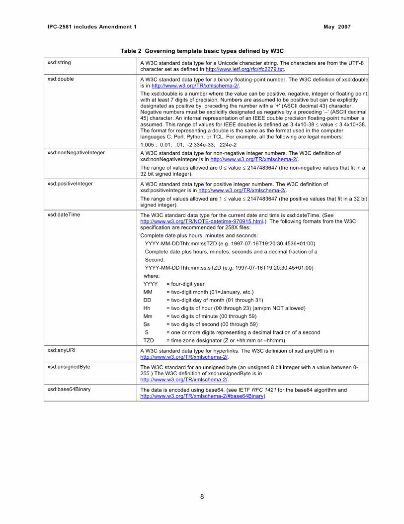
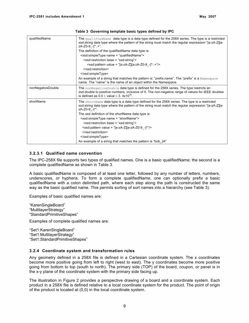
Table 2 defines those W3C basic types that are used to define attributes in the 258X schema. The xsd:string type is constrained to create specific base types for special purpose strings, such as qualifiedName and shortName. The rules for special number types and the date format are also defined. Table 3 defines those basic types that have been standardized for use within the IPC-258X format.
7
IPC-2581 includes Amendment 1 May 2007
Table 2 Governing template basic types defined by W3C
xsd:string A W3C standard data type for a Unicode character string. The characters are from the UTF-8 character set as defined in http://www.ietf.org/rfc/rfc2279.txt.
xsd:double A W3C standard data type for a binary floating-point number. The W3C definition of xsd:double is in http://www.w3.org/TR/xmlschema-2/. The xsd:double is a number where the value can be positive, negative, integer or floating point,with at least 7 digits of precision. Numbers are assumed to be positive but can be explicitly designated as positive by preceding the number with a ‘+’ (ASCII decimal 43) character. Negative numbers must be explicitly designated as negative by a preceding ‘–‘ (ASCII decimal 45) character. An internal representation of an IEEE double precision floating-point number is assumed. This range of values for IEEE doubles is defined as 3.4x10-38 ≤ value ≤ 3.4x10+38. The format for representing a double is the same as the format used in the computer languages C, Perl, Python, or TCL. For example, all the following are legal numbers: 1.005 ; 0.01; .01; -2.334e-33; .224e-2
xsd:nonNegativeInteger A W3C standard data type for non-negative integer numbers. The W3C definition of xsd:nonNegativeInteger is in http://www.w3.org/TR/xmlschema-2/. The range of values allowed are 0 ≤ value ≤ 2147483647 (the non-negative values that fit in a 32 bit signed integer).
xsd:positiveInteger A W3C standard data type for positive integer numbers. The W3C definition of xsd:positiveInteger is in http://www.w3.org/TR/xmlschema-2/. The range of values allowed are 1 ≤ value ≤ 2147483647 (the positive values that fit in a 32 bit signed integer).
xsd:dateTime The W3C standard data type for the current date and time is xsd:dateTime. (See http://www.w3.org/TR/NOTE-datetime-970915.html.) The following formats from the W3C specification are recommended for 258X files: Complete date plus hours, minutes and seconds: YYYY-MM-DDThh:mm:ssTZD (e.g. 1997-07-16T19:20:30.4536+01:00) Complete date plus hours, minutes, seconds and a decimal fraction of a Second: YYYY-MM-DDThh:mm:ss.sTZD (e.g. 1997-07-16T19:20:30.45+01:00)
where: YYYY = four-digit year MM = two-digit month (01=January, etc.) DD = two-digit day of month (01 through 31) Hh = two digits of hour (00 through 23) (am/pm NOT allowed) Mm = two digits of minute (00 through 59) Ss = two digits of second (00 through 59) S = one or more digits representing a decimal fraction of a second TZD = time zone designator (Z or +hh:mm or –hh:mm)
xsd:anyURI A W3C standard data type for hyperlinks. The W3C definition of xsd:anyURI is in http://www.w3.org/TR/xmlschema-2/.
xsd:unsignedByte The W3C standard for an unsigned byte (an unsigned 8 bit integer with a value between 0-255.) The W3C definition of xsd:unsignedByte is in http://www.w3.org/TR/xmlschema-2/.
xsd:base64Binary The data is encoded using base64. (see IETF RFC 1421 for the base64 algorithm and http://www.w3.org/TR/xmlschema-2/#base64Binary)
8
IPC-2581 includes Amendment 1 May 2007
Table 3 Governing template basic types defined by IPC
qualifiedName The qualifiedName data type is a data type defined for the 258X series. The type is a restricted xsd:string data type where the pattern of the string must match the regular expression “[a-zA-Z][a-zA-Z0-9_-]*:.+”. The definition of the qualifiedName data type is: <xsd:simpleType name = “qualifiedName”> <xsd:restriction base = “xsd:string”> <xsd:pattern value = “[a-zA-Z][a-zA-Z0-9_-]*:.+”/> </xsd:restriction> </xsd:simpleType> An example of a string that matches the pattern is: “prefix:name”. The “prefix” is a Namespace name. The “name” is the name of an object within the Namespace.
nonNegativeDouble The nonNegativeDouble data type is defined for the 258X series. The type restricts an xsd:double to positive numbers, inclusive of 0. The non-negative range of values for IEEE doubles is defined as 0.0 ≤ value ≤ 3. 4x1038.
shortName The shortName data type is a data type defined for the 258X series. The type is a restricted xsd:string data type where the pattern of the string must match the regular expression “[a-zA-Z][a-zA-Z0-9_-]*”. The xsd definition of the shortName data type is: <xsd:simpleType name = “shortName”> <xsd:restriction base = “xsd:string”> <xsd:pattern value = “[a-zA-Z][a-zA-Z0-9_-]*”/> </xsd:restriction> </xsd:simpleType> An example of a string that matches the pattern is “bob_24”
3.2.3.1 Qualified name convention The IPC-258X file supports two types of qualified names. One is a basic qualifiedName; the second is a complete qualifiedName as shown in Table 3.
A basic qualifiedName is composed of at least one letter, followed by any number of letters, numbers, underscores, or hyphens. To form a complete qualifiedName, one can optionally prefix a basic qualifiedName with a colon delimited path, where each step along the path is constructed the same way as the basic qualified name. This permits sorting of sort names into a hierarchy (see Table 3).
Examples of basic qualified names are:
“KarenSingleBoard” “MultilayerStrategy” “StandardPrimitiveShapes” Examples of complete qualified names are:
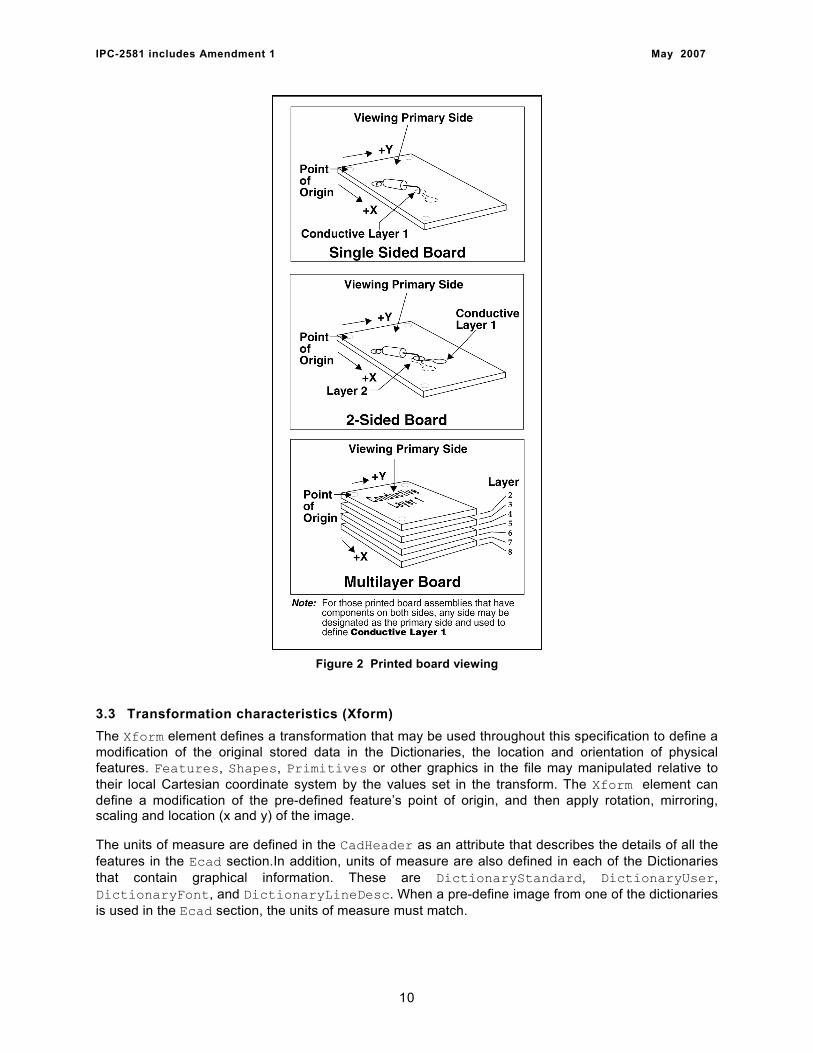
“Set1:KarenSingleBoard” “Set1:MultilayerStrategy” “Set1:StandardPrimitiveShapes” 3.2.4 Coordinate system and transformation rules Any geometry defined in a 258X file is defined in a Cartesian coordinate system. The x coordinates become more positive going from left to right (west to east). The y coordinates become more positive going from bottom to top (south to north). The primary side (TOP) of the board, coupon, or panel is in the x-y plane of the coordinate system with the primary side facing up.
The illustration in Figure 2 provides a perspective drawing of a board and a coordinate system. Each product in a 258X file is defined relative to a local coordinate system for the product. The point of origin of the product is located at (0,0) in the local coordinate system.
9
IPC-2581 includes Amendment 1 May 2007
Figure 2 Printed board viewing
3.3 Transformation characteristics (Xform) The Xform element defines a transformation that may be used throughout this specification to define a modification of the original stored data in the Dictionaries, the location and orientation of physical features. Features, Shapes, Primitives or other graphics in the file may manipulated relative to their local Cartesian coordinate system by the values set in the transform. The Xform element can define a modification of the pre-defined feature’s point of origin, and then apply rotation, mirroring, scaling and location (x and y) of the image.
The units of measure are defined in the CadHeader as an attribute that describes the details of all the features in the Ecad section.In addition, units of measure are also defined in each of the Dictionaries that contain graphical information. These are DictionaryStandard, DictionaryUser, DictionaryFont, and DictionaryLineDesc. When a pre-define image from one of the dictionaries is used in the Ecad section, the units of measure must match.
10
IPC-2581 includes Amendment 1 May 2007
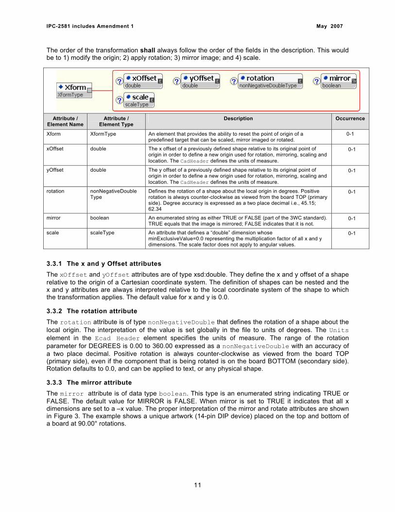
The order of the transformation shall always follow the order of the fields in the description. This would be to 1) modify the origin; 2) apply rotation; 3) mirror image; and 4) scale.
Attribute / Element Name
Attribute / Element Type
Description Occurrence
Xform XformType An element that provides the ability to reset the point of origin of a predefined target that can be scaled, mirror imaged or rotated.
0-1
xOffset double The x offset of a previously defined shape relative to its original point of origin in order to define a new origin used for rotation, mirroring, scaling and location. The CadHeader defines the units of measure.
0-1
yOffset double The y offset of a previously defined shape relative to its original point of origin in order to define a new origin used for rotation, mirroring, scaling and location. The CadHeader defines the units of measure.
0-1
rotation nonNegativeDouble Type
Defines the rotation of a shape about the local origin in degrees. Positive rotation is always counter-clockwise as viewed from the board TOP (primary side). Degree accuracy is expressed as a two place decimal i.e., 45.15; 62.34
0-1
mirror boolean An enumerated string as either TRUE or FALSE (part of the 3WC standard). TRUE equals that the image is mirrored; FALSE indicates that it is not.
0-1
scale scaleType An attribute that defines a “double” dimension whose minExclusiveValue=0.0 representing the multiplication factor of all x and y dimensions. The scale factor does not apply to angular values.
0-1
3.3.1 The x and y Offset attributes The xOffset and yOffset attributes are of type xsd:double. They define the x and y offset of a shape relative to the origin of a Cartesian coordinate system. The definition of shapes can be nested and the x and y attributes are always interpreted relative to the local coordinate system of the shape to which the transformation applies. The default value for x and y is 0.0.
3.3.2 The rotation attribute The rotation attribute is of type nonNegativeDouble that defines the rotation of a shape about the local origin. The interpretation of the value is set globally in the file to units of degrees. The Units element in the Ecad Header element specifies the units of measure. The range of the rotation parameter for DEGREES is 0.00 to 360.00 expressed as a nonNegativeDouble with an accuracy of a two place decimal. Positive rotation is always counter-clockwise as viewed from the board TOP (primary side), even if the component that is being rotated is on the board BOTTOM (secondary side). Rotation defaults to 0.0, and can be applied to text, or any physical shape.
3.3.3 The mirror attribute The mirror attribute is of data type boolean. This type is an enumerated string indicating TRUE or FALSE. The default value for MIRROR is FALSE. When mirror is set to TRUE it indicates that all x dimensions are set to a –x value. The proper interpretation of the mirror and rotate attributes are shown in Figure 3. The example shows a unique artwork (14-pin DIP device) placed on the top and bottom of a board at 90.00° rotations.
11

IPC-2581 includes Amendment 1 May 2007
3.3.4 The scale attribute The scale attribute is of data type scaleType. The scale attribute is a “double” that must have a value greater than zero. All x and y dimensions of a geometry are multiplied by the scale attribute. The scale factor does not apply to angular values. The default value is 1.0.
3.3.5 The x and y Location attributes The xLocation and yLocation attributes are of type xsd:double. They define the x and y position where a feature, component, text or other shape is placed. The xLocation and yLocation coordinate positions a shape by its original origin or its modified origin (x and y Offset) relative to the origin of the image upon which the feature, component etc. is to be located. Mirroring, rotating, and scaling may all apply to the location of the shape as indicated by the Xform.
Figure 3 Mirror and Rotation Diagram
3.4 Substitution groups The IPC-2581 uses the concept of substitution within the XML schema. Various groups of elements have been identified in the body of the standard and have been designated as having a specific focus or purpose. Within the schema, these substitution groups are provided with a name. When a group exists and if they are required according to the instances of the schema, it is mandatory that the substitution name be replaced by one of the acceptable descriptions identified within the group.
Often a schema needs to specify that one of several different XML Elements can be used with equal validity. For example, in every case where a Triangle can be used, it is also permissible to use a Diamond, Hexagon, Octagon, Oval, or one of several others: even though these shapes are quite different, they are equivalent as far as the schema is concerned. IPC-2581 handles this by using “substitution groups.”
12
IPC-2581 includes Amendment 1 May 2007
A substitution group consists of two types of elements: a “head”, and elements which may substitute for the head. Furthermore, when the head is denoted as ABSTRACT, the substitution is required, rather than optional. In IPC-2581, the heads of all substitution groups are ABSTRACT. Thus, it means that a valid instance document is not allowed to contain a StandardPrimitive element, but instead, (where StandardPrimitive is called for in the schema) a Triangle, Diamond, Hexagon, etc. must be used.
It should be noted that the head of one substitution group may be used within a different substitution group. As an example, the StandardPrimitive element is part of the StandardShape substitution group, which in turn is part of the Feature substitution group. This means that a Triangle, Diamond, Hexagon, etc may be used wherever a Feature or StandardShape is called for, as well as wherever a StandardPrimitive is called for.
IPC-2581 features several dictionaries that permit specifying some type of information (such as a StandardPrimitive or a LineDesc) one time, and to reuse that definition as often as necessary. Some substitution groups in IPC-2581 are present to enable specifying either a dictionary entry or the same kind of information defined in specific detail within the body of the file. Any predefined image contained in the Dictionaries must have a unique “id”. It is the “id” name that is used to instantiate information from any of the dictionaries.
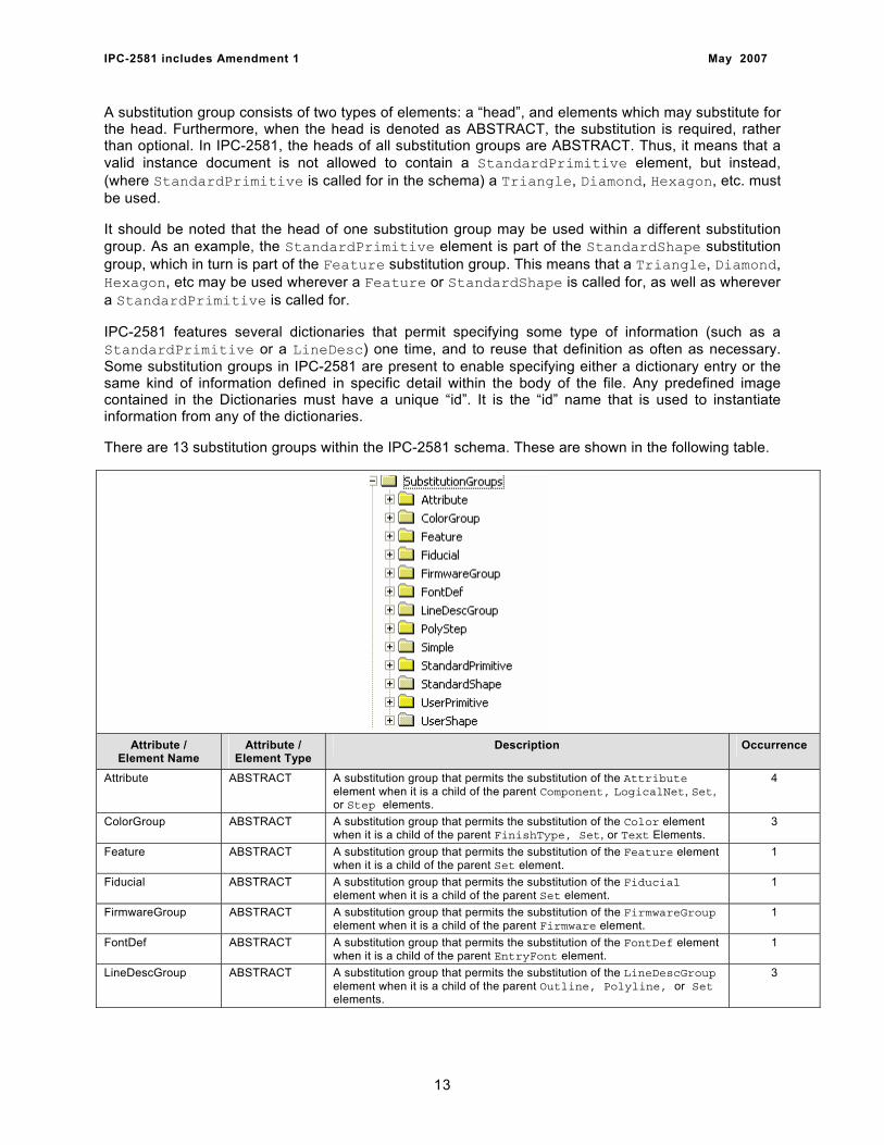
There are 13 substitution groups within the IPC-2581 schema. These are shown in the following table.
Attribute / Element Name
Attribute / Element Type
Description Occurrence
Attribute ABSTRACT A substitution group that permits the substitution of the Attribute element when it is a child of the parent Component, LogicalNet, Set, or Step elements.
4
ColorGroup ABSTRACT A substitution group that permits the substitution of the Color element when it is a child of the parent FinishType, Set, or Text Elements.
3
Feature ABSTRACT A substitution group that permits the substitution of the Feature element when it is a child of the parent Set element.
1
Fiducial ABSTRACT A substitution group that permits the substitution of the Fiducial element when it is a child of the parent Set element.
1
FirmwareGroup ABSTRACT A substitution group that permits the substitution of the FirmwareGroup element when it is a child of the parent Firmware element.
1
FontDef ABSTRACT A substitution group that permits the substitution of the FontDef element when it is a child of the parent EntryFont element.
1
LineDescGroup ABSTRACT A substitution group that permits the substitution of the LineDescGroup element when it is a child of the parent Outline, Polyline, or Set elements.
3
13
IPC-2581 includes Amendment 1 May 2007
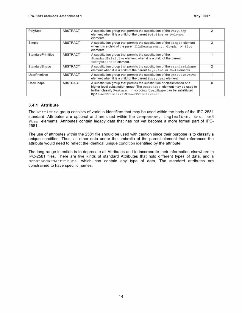
PolyStep ABSTRACT A substitution group that permits the substitution of the PolyStep element when it is a child of the parent Polyline or Polygon elements.
2
Simple ABSTRACT A substitution group that permits the substitution of the Simple element when it is a child of the parent DfxMeasurement, Glyph, or Slot elements.
3
StandardPrimitive ABSTRACT A substitution group that permits the substitution of the StandardPrimitive element when it is a child of the parent EntryStandard element.
1
StandardShape ABSTRACT A substitution group that permits the substitution of the StandardShape element when it is a child of the parent LayerPad or Pad elements.
2
UserPrimitive ABSTRACT A substitution group that permits the substitution of the UserPrimitive element when it is a child of the parent EntryUser element.
1
UserShape ABSTRACT A substitution group that permits the substitution or classification of a higher level substitution group. The UserShape element may be used to further classify Feature. In so doing, UserShape can be substituted by a UserPrimitive or UserPrimitiveRef.
0
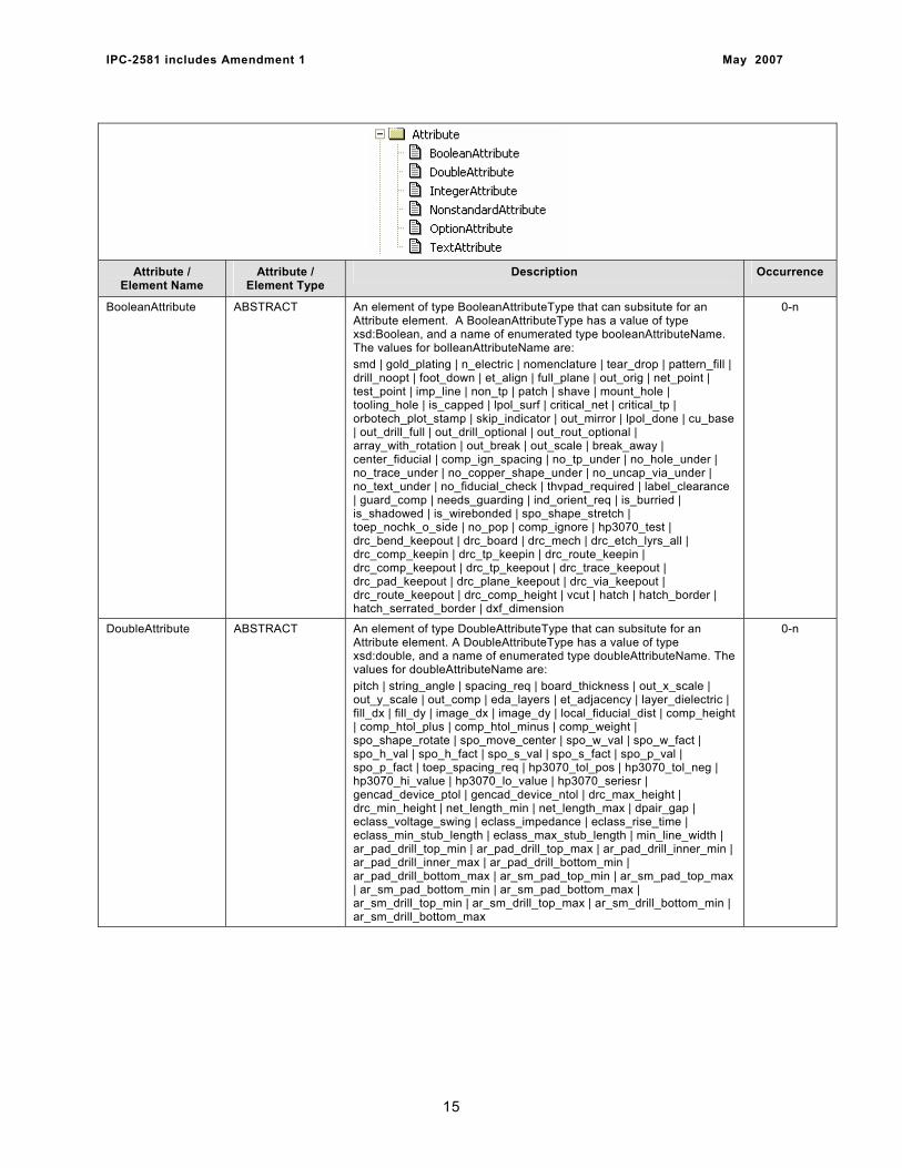
3.4.1 Attribute The Attribute group consists of various identifiers that may be used within the body of the IPC-2581 standard. Attributes are optional and are used within the Component, LogicalNet, Set, and Step elements. Attributes contain legacy data that has not yet become a more formal part of IPC-2581.
The use of attributes within the 2581 file should be used with caution since their purpose is to classify a unique condition. Thus, all other data under the umbrella of the parent element that references the attribute would need to reflect the identical unique condition identified by the attribute.
The long range intention is to deprecate all Attributes and to incorporate their information elsewhere in IPC-2581 files. There are five kinds of standard Attributes that hold different types of data, and a NonstandardAttribute which can contain any type of data. The standard attributes are constrained to have specific names.
14
IPC-2581 includes Amendment 1 May 2007
Attribute / Element Name
Attribute / Element Type
Description Occurrence
BooleanAttribute ABSTRACT An element of type BooleanAttributeType that can subsitute for an Attribute element. A BooleanAttributeType has a value of type xsd:Boolean, and a name of enumerated type booleanAttributeName. The values for bolleanAttributeName are: smd | gold_plating | n_electric | nomenclature | tear_drop | pattern_fill | drill_noopt | foot_down | et_align | full_plane | out_orig | net_point | test_point | imp_line | non_tp | patch | shave | mount_hole | tooling_hole | is_capped | lpol_surf | critical_net | critical_tp | orbotech_plot_stamp | skip_indicator | out_mirror | lpol_done | cu_base | out_drill_full | out_drill_optional | out_rout_optional | array_with_rotation | out_break | out_scale | break_away | center_fiducial | comp_ign_spacing | no_tp_under | no_hole_under | no_trace_under | no_copper_shape_under | no_uncap_via_under | no_text_under | no_fiducial_check | thvpad_required | label_clearance | guard_comp | needs_guarding | ind_orient_req | is_burried | is_shadowed | is_wirebonded | spo_shape_stretch | toep_nochk_o_side | no_pop | comp_ignore | hp3070_test | drc_bend_keepout | drc_board | drc_mech | drc_etch_lyrs_all | drc_comp_keepin | drc_tp_keepin | drc_route_keepin | drc_comp_keepout | drc_tp_keepout | drc_trace_keepout | drc_pad_keepout | drc_plane_keepout | drc_via_keepout | drc_route_keepout | drc_comp_height | vcut | hatch | hatch_border | hatch_serrated_border | dxf_dimension
0-n
DoubleAttribute ABSTRACT An element of type DoubleAttributeType that can subsitute for an Attribute element. A DoubleAttributeType has a value of type xsd:double, and a name of enumerated type doubleAttributeName. The values for doubleAttributeName are: pitch | string_angle | spacing_req | board_thickness | out_x_scale | out_y_scale | out_comp | eda_layers | et_adjacency | layer_dielectric | fill_dx | fill_dy | image_dx | image_dy | local_fiducial_dist | comp_height | comp_htol_plus | comp_htol_minus | comp_weight | spo_shape_rotate | spo_move_center | spo_w_val | spo_w_fact | spo_h_val | spo_h_fact | spo_s_val | spo_s_fact | spo_p_val | spo_p_fact | toep_spacing_req | hp3070_tol_pos | hp3070_tol_neg | hp3070_hi_value | hp3070_lo_value | hp3070_seriesr | gencad_device_ptol | gencad_device_ntol | drc_max_height | drc_min_height | net_length_min | net_length_max | dpair_gap | eclass_voltage_swing | eclass_impedance | eclass_rise_time | eclass_min_stub_length | eclass_max_stub_length | min_line_width | ar_pad_drill_top_min | ar_pad_drill_top_max | ar_pad_drill_inner_min | ar_pad_drill_inner_max | ar_pad_drill_bottom_min | ar_pad_drill_bottom_max | ar_sm_pad_top_min | ar_sm_pad_top_max | ar_sm_pad_bottom_min | ar_sm_pad_bottom_max | ar_sm_drill_top_min | ar_sm_drill_top_max | ar_sm_drill_bottom_min | ar_sm_drill_bottom_max
0-n
15
IPC-2581 includes Amendment 1 May 2007
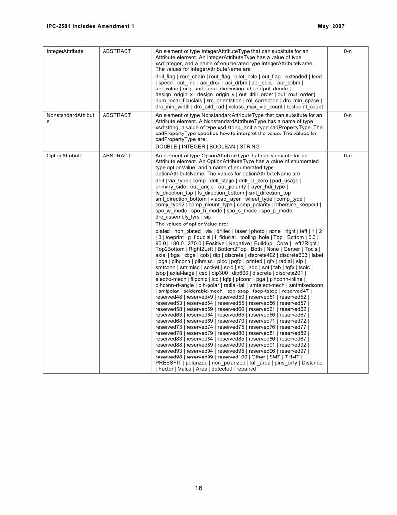
IntegerAttribute ABSTRACT An element of type IntegerAttributeType that can subsitute for an Attribute element. An IntegerAttributeType has a value of type xsd:integer, and a name of enumerated type integerAttributeName. The values for integerAttributeName are: drill_flag | rout_chain | rout_flag | pilot_hole | out_flag | extended | feed | speed | cut_line | aoi_drcu | aoi_drbm | aoi_cpcu | aoi_cpbm | aoi_value | orig_surf | eda_dimension_id | output_dcode | design_origin_x | design_origin_y | out_drill_order | out_rout_order | num_local_fiducials | src_orientation | rot_correction | drc_min_space | drc_min_width | drc_add_rad | eclass_max_via_count | testpoint_count
0-n
NonstandardAttribute
ABSTRACT An element of type NonstandardAttributeType that can subsitute for an Attribute element. A NonstandardAttributeType has a name of type xsd:string, a value of type xsd:string, and a type cadPropertyType. The cadPropertyType specifies how to interpret the value. The values for cadPropertyType are: DOUBLE | INTEGER | BOOLEAN | STRING
0-n
OptionAttribute ABSTRACT An element of type OptionAttributeType that can subsitute for an Attribute element. An OptionAttributeType has a value of enumerated type optionValue, and a name of enumerated type optionAttributeName. The values for optionAttributeName are: drill | via_type | comp | drill_stage | drill_sr_zero | pad_usage | primary_side | out_angle | out_polarity | layer_hdi_type | fs_direction_top | fs_direction_bottom | smt_direction_top | smt_direction_bottom | viacap_layer | wheel_type | comp_type | comp_type2 | comp_mount_type | comp_polarity | otherside_keepout | spo_w_mode | spo_h_mode | spo_s_mode | spo_p_mode | drc_assembly_lyrs | sip The values of optionValue are: plated | non_plated | via | drilled | laser | photo | none | right | left | 1 | 2 | 3 | toeprint | g_fiducial | l_fiducial | tooling_hole | Top | Bottom | 0.0 | 90.0 | 180.0 | 270.0 | Positive | Negative | Buildup | Core | Left2Right | Top2Bottom | Right2Left | Bottom2Top | Both | None | Gerber | Tools | axial | bga | cbga | cob | dip | discrete | discrete402 | discrete603 | label | pga | pihconn | pihmisc | plcc | pqfp | printed | qfp | radial | sip | smtconn | smtmisc | socket | soic | soj | sop | sot | tab | tqfp | tsoic | tsop | axial-large | csp | dip300 | dip600 | discrete | discrete201 | electro-mech | flipchip | lcc | lqfp | pfconn | pga | pihconn-inline | pihconn-rt-angle | pih-polar | radial-tall | smtelect-mech | smtmixedconn | smtpolar | solderable-mech | sop-ssop | tsop-tssop | reserved47 | reserved48 | reserved49 | reserved50 | reserved51 | reserved52 | reserved53 | reserved54 | reserved55 | reserved56 | reserved57 | reserved58 | reserved59 | reserved60 | reserved61 | reserved62 | reserved63 | reserved64 | reserved65 | reserved66 | reserved67 | reserved68 | reserved69 | reserved70 | reserved71 | reserved72 | reserved73 | reserved74 | reserved75 | reserved76 | reserved77 | reserved78 | reserved79 | reserved80 | reserved81 | reserved82 | reserved83 | reserved84 | reserved85 | reserved86 | reserved87 | reserved88 | reserved89 | reserved90 | reserved91 | reserved92 | reserved93 | reserved94 | reserved95 | reserved96 | reserved97 | reserved98 | reserved99 | reserved100 | Other | SMT | THMT | PRESSFIT | polarized | non_polarized | full_area | pins_only | Distance | Factor | Value | Area | detected | repaired
0-n
16
IPC-2581 includes Amendment 1 May 2007
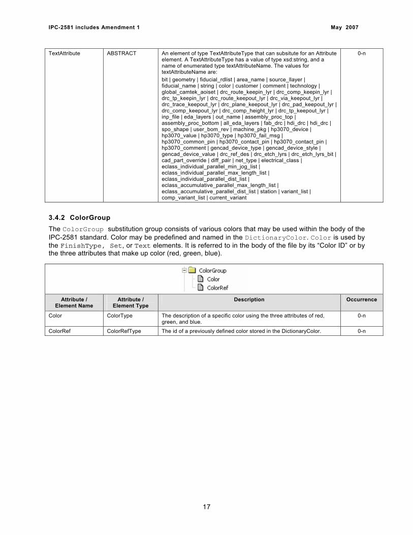
TextAttribute ABSTRACT An element of type TextAttributeType that can subsitute for an Attribute element. A TextAttributeType has a value of type xsd:string, and a name of enumerated type textAttributeName. The values for textAttributeName are: bit | geometry | fiducial_rdlist | area_name | source_llayer | fiducial_name | string | color | customer | comment | technology | global_camtek_aoiset | drc_route_keepin_lyr | drc_comp_keepin_lyr | drc_tp_keepin_lyr | drc_route_keepout_lyr | drc_via_keepout_lyr | drc_trace_keepout_lyr | drc_plane_keepout_lyr | drc_pad_keepout_lyr | drc_comp_keepout_lyr | drc_comp_height_lyr | drc_tp_keepout_lyr | inp_file | eda_layers | out_name | assembly_proc_top | assembly_proc_bottom | all_eda_layers | fab_drc | hdi_drc | hdi_drc | spo_shape | user_bom_rev | machine_pkg | hp3070_device | hp3070_value | hp3070_type | hp3070_fail_msg | hp3070_common_pin | hp3070_contact_pin | hp3070_contact_pin | hp3070_comment | gencad_device_type | gencad_device_style | gencad_device_value | drc_ref_des | drc_etch_lyrs | drc_etch_lyrs_bit | cad_part_override | diff_pair | net_type | electrical_class | eclass_individual_parallel_min_jog_list | eclass_individual_parallel_max_length_list | eclass_individual_parallel_dist_list | eclass_accumulative_parallel_max_length_list | eclass_accumulative_parallel_dist_list | station | variant_list | comp_variant_list | current_variant
0-n
3.4.2 ColorGroup The ColorGroup substitution group consists of various colors that may be used within the body of the IPC-2581 standard. Color may be predefined and named in the DictionaryColor. Color is used by the FinishType, Set, or Text elements. It is referred to in the body of the file by its “Color ID” or by the three attributes that make up color (red, green, blue).
Attribute / Element Name
Attribute / Element Type
Description Occurrence
Color ColorType The description of a specific color using the three attributes of red, green, and blue.
0-n
ColorRef ColorRefType The id of a previously defined color stored in the DictionaryColor. 0-n
17
IPC-2581 includes Amendment 1 May 2007
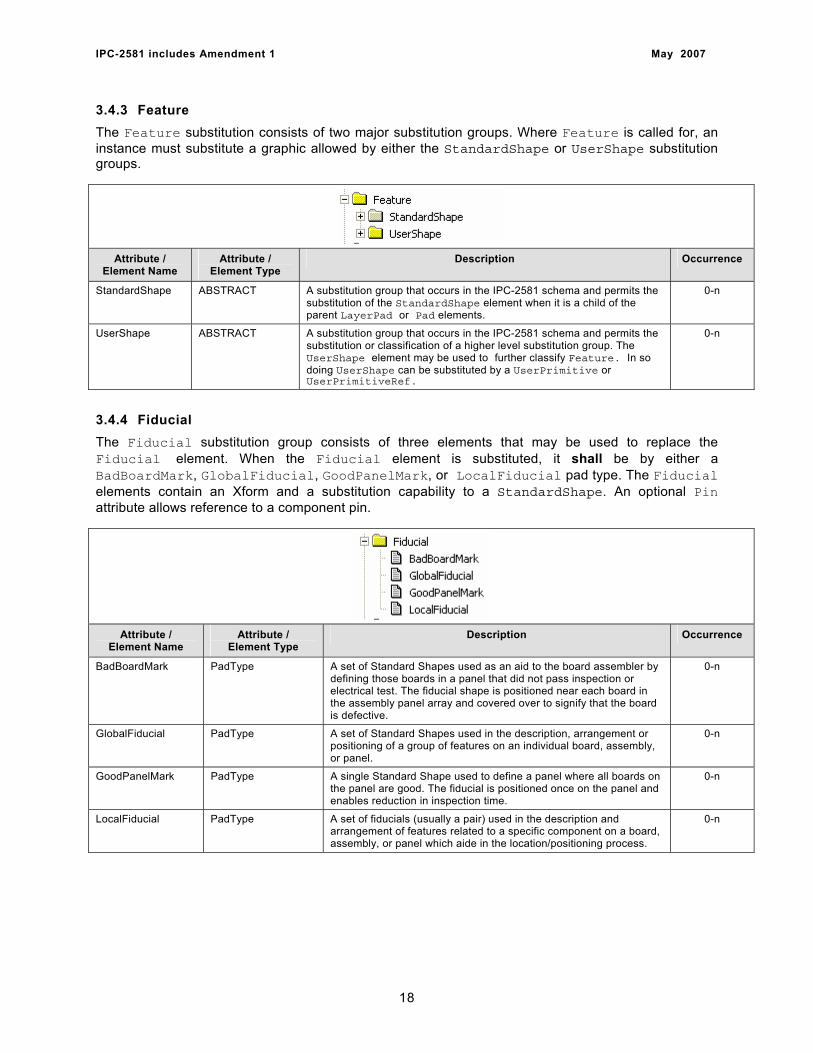
3.4.3 Feature The Feature substitution consists of two major substitution groups. Where Feature is called for, an instance must substitute a graphic allowed by either the StandardShape or UserShape substitution groups.
Attribute / Element Name
Attribute / Element Type
Description Occurrence
StandardShape ABSTRACT A substitution group that occurs in the IPC-2581 schema and permits the substitution of the StandardShape element when it is a child of the parent LayerPad or Pad elements.
0-n
UserShape ABSTRACT A substitution group that occurs in the IPC-2581 schema and permits the substitution or classification of a higher level substitution group. The UserShape element may be used to further classify Feature. In so doing UserShape can be substituted by a UserPrimitive or UserPrimitiveRef.
0-n
3.4.4 Fiducial The Fiducial substitution group consists of three elements that may be used to replace the Fiducial element. When the Fiducial element is substituted, it shall be by either a BadBoardMark, GlobalFiducial, GoodPanelMark, or LocalFiducial pad type. The Fiducial elements contain an Xform and a substitution capability to a StandardShape. An optional Pin attribute allows reference to a component pin.
Attribute / Element Name
Attribute / Element Type
Description Occurrence
BadBoardMark PadType A set of Standard Shapes used as an aid to the board assembler by defining those boards in a panel that did not pass inspection or electrical test. The fiducial shape is positioned near each board in the assembly panel array and covered over to signify that the board is defective.
0-n
GlobalFiducial PadType A set of Standard Shapes used in the description, arrangement or positioning of a group of features on an individual board, assembly, or panel.
0-n
GoodPanelMark PadType A single Standard Shape used to define a panel where all boards on the panel are good. The fiducial is positioned once on the panel and enables reduction in inspection time.
0-n
LocalFiducial PadType A set of fiducials (usually a pair) used in the description and arrangement of features related to a specific component on a board, assembly, or panel which aide in the location/positioning process.
0-n
18
IPC-2581 includes Amendment 1 May 2007
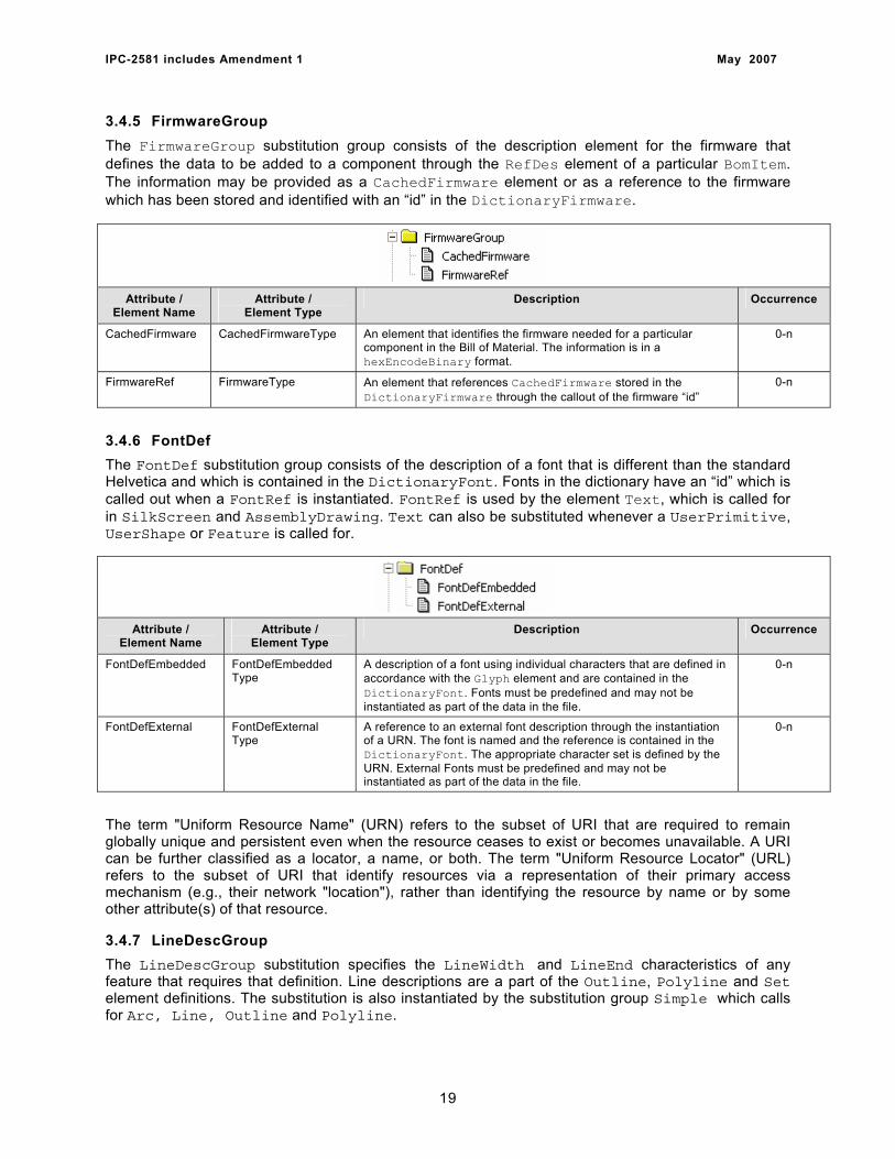
3.4.5 FirmwareGroup The FirmwareGroup substitution group consists of the description element for the firmware that defines the data to be added to a component through the RefDes element of a particular BomItem. The information may be provided as a CachedFirmware element or as a reference to the firmware which has been stored and identified with an “id” in the DictionaryFirmware.
Attribute / Element Name
Attribute / Element Type
Description Occurrence
CachedFirmware CachedFirmwareType An element that identifies the firmware needed for a particular component in the Bill of Material. The information is in a hexEncodeBinary format.
0-n
FirmwareRef FirmwareType An element that references CachedFirmware stored in the DictionaryFirmware through the callout of the firmware “id”
0-n
3.4.6 FontDef The FontDef substitution group consists of the description of a font that is different than the standard Helvetica and which is contained in the DictionaryFont. Fonts in the dictionary have an “id” which is called out when a FontRef is instantiated. FontRef is used by the element Text, which is called for in SilkScreen and AssemblyDrawing. Text can also be substituted whenever a UserPrimitive, UserShape or Feature is called for.
Attribute / Element Name
Attribute / Element Type
Description Occurrence
FontDefEmbedded FontDefEmbedded Type
A description of a font using individual characters that are defined in accordance with the Glyph element and are contained in the DictionaryFont. Fonts must be predefined and may not be instantiated as part of the data in the file.
0-n
FontDefExternal FontDefExternal Type
A reference to an external font description through the instantiation of a URN. The font is named and the reference is contained in the DictionaryFont. The appropriate character set is defined by the URN. External Fonts must be predefined and may not be instantiated as part of the data in the file.
0-n
The term "Uniform Resource Name" (URN) refers to the subset of URI that are required to remain globally unique and persistent even when the resource ceases to exist or becomes unavailable. A URI can be further classified as a locator, a name, or both. The term "Uniform Resource Locator" (URL) refers to the subset of URI that identify resources via a representation of their primary access mechanism (e.g., their network "location"), rather than identifying the resource by name or by some other attribute(s) of that resource.
3.4.7 LineDescGroup The LineDescGroup substitution specifies the LineWidth and LineEnd characteristics of any feature that requires that definition. Line descriptions are a part of the Outline, Polyline and Set element definitions. The substitution is also instantiated by the substitution group Simple which calls for Arc, Line, Outline and Polyline.
19

IPC-2581 includes Amendment 1 May 2007
Attribute / Element Name
Attribute / Element Type
Description Occurrence
LineDesc LineDescType An element that identifies the LineEnd and LineWidth characteristics
0-n
LineDescRef LineDescRefType A reference to a LineDesc that is contained in the DictionaryLineDesc and identified by its unique “id”. The units for the dictionary are defined and must be consistent with the units of the CadHeader when referenced from the Ecad section.
0-n
3.4.8 PolyStep The Polystep substitution consists of defining either a Line or an Arc as the continuation of a Polyline or Polygon description. The location information is interpreted as being the point to which the curve (Arc), or segment (Line) is drawn. The substitution may take place anywhere within the file where the elements Polyline and Outline occur. This action includes the dictionaries where graphic descriptions are predefined. The Units of measure must be consistent with the Units parameter of the three dictionaries where this substitution can take place; DictionaryStandard, DictionaryUser, and DictionaryFont.
Attribute / Element Name
Attribute / Element Type
Description Occurrence
PolyStepCurve PolyStepCurveType The continuation of the linear description of a Polyline or Polygon if the next portion to be defined is an arc. The end point of the arc is defined as well as the location of the radius. CounterClockwise is the default direction
0-n
PolyStepSegment PolyStepSegmentType The continuation of the linear description of a Polyline or Polygon if the next portion to be defined is a line segment. The end point of the line is defined.
0-n
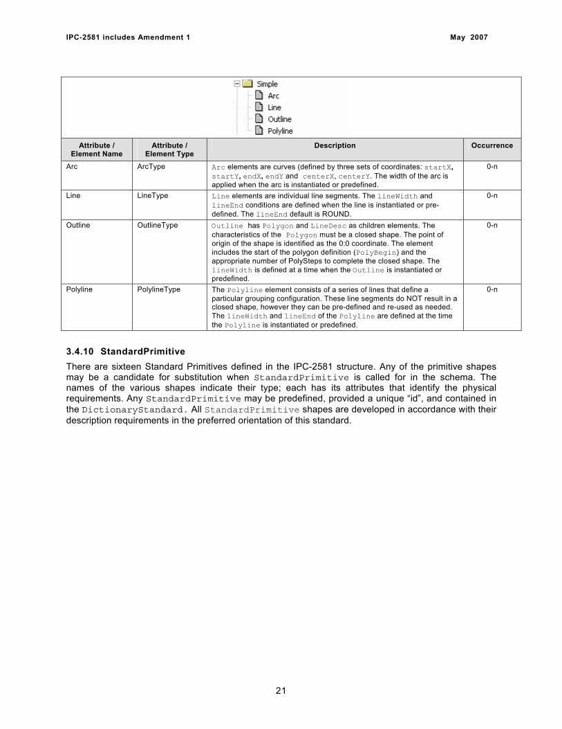
3.4.9 Simple The Simple substitution consists of defining an Arc, Line, Outline or Polyline. The Simple substitution is called for in the DfxMeasurement, Glyph, and Slot elements. Simple is also identified as a UserPrimitive, UserShape, or Feature and the four elements may be substituted when called for in conjunction with those descriptions. When predefined in the DictionaryUser, or DictionaryFont the Units must match those of the dictionary.
20
IPC-2581 includes Amendment 1 May 2007
Attribute / Element Name
Attribute / Element Type
Description Occurrence
Arc ArcType Arc elements are curves (defined by three sets of coordinates: startX, startY, endX, endY and centerX, centerY. The width of the arc is applied when the arc is instantiated or predefined.
0-n
Line LineType Line elements are individual line segments. The lineWidth and lineEnd conditions are defined when the line is instantiated or pre-defined. The lineEnd default is ROUND.
0-n
Outline OutlineType Outline has Polygon and LineDesc as children elements. The characteristics of the Polygon must be a closed shape. The point of origin of the shape is identified as the 0:0 coordinate. The element includes the start of the polygon definition (PolyBegin) and the appropriate number of PolySteps to complete the closed shape. The lineWidth is defined at a time when the Outline is instantiated or predefined.
0-n
Polyline PolylineType The Polyline element consists of a series of lines that define a particular grouping configuration. These line segments do NOT result in a closed shape, however they can be pre-defined and re-used as needed. The lineWidth and lineEnd of the Polyline are defined at the time the Polyline is instantiated or predefined.
0-n
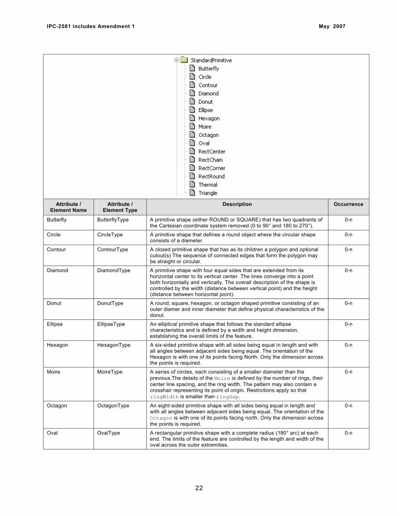
3.4.10 StandardPrimitive There are sixteen Standard Primitives defined in the IPC-2581 structure. Any of the primitive shapes may be a candidate for substitution when StandardPrimitive is called for in the schema. The names of the various shapes indicate their type; each has its attributes that identify the physical requirements. Any StandardPrimitive may be predefined, provided a unique “id”, and contained in the DictionaryStandard. All StandardPrimitive shapes are developed in accordance with their description requirements in the preferred orientation of this standard.
21
IPC-2581 includes Amendment 1 May 2007
Attribute / Element Name
Attribute / Element Type
Description Occurrence
Butterfly ButterflyType A primitive shape (either ROUND or SQUARE) that has two quadrants of the Cartesian coordinate system removed (0 to 90° and 180 to 270°).
0-n
Circle CircleType A primitive shape that defines a round object where the circular shape consists of a diameter.
0-n
Contour ContourType A closed primitive shape that has as its children a polygon and optional cutout(s) The sequence of connected edges that form the polygon may be straight or circular.
0-n
Diamond DiamondType A primitive shape with four equal sides that are extended from its horizontal center to its vertical center. The lines converge into a point both horizontally and vertically. The overall description of the shape is controlled by the width (distance between vertical point) and the height (distance between horizontal point).
0-n
Donut DonutType A round, square, hexagon, or octagon shaped primitive consisting of an outer diamer and inner diameter that define physical characteristics of the donut.
0-n
Ellipse EllipseType An elliptical primitive shape that follows the standard ellipse characteristics and is defined by a width and height dimension, establishing the overall limits of the feature.
0-n
Hexagon HexagonType A six-sided primitive shape with all sides being equal in length and with all angles between adjacent sides being equal. The orientation of the Hexagon is with one of its points facing North. Only the dimension across the points is required.
0-n
Moire MoireType A series of circles, each consisting of a smaller diameter than the previous.The details of the Moire is defined by the number of rings, their center line spacing, and the ring width. The pattern may also contain a crosshair representing its point of origin. Restrictions apply so that ringWidth is smaller than ringGap.
0-n
Octagon OctagonType An eight-sided primitive shape with all sides being equal in length and with all angles between adjacent sides being equal. The orientation of the Octagon is with one of its points facing north. Only the dimension across the points is required.
0-n
Oval OvalType A rectangular primitive shape with a complete radius (180° arc) at each end. The limits of the feature are controlled by the length and width of the oval across the outer extremities.
0-n
22

IPC-2581 includes Amendment 1 May 2007
RectCenter RectCenterType The characteristics of a rectangle defined by a width and height dimension consistent with a horizontal position on the Cartesian coordinate system. The center point is the point of origin and is used to locate the RectCenter. A “square” is a RectCenter with the width and height equal.
0-n
RectCham RectChamType A rectangle with one or more corners chamfered. The user has the option to define any of the corners as containing the chamfer as well as the chamfered dimensions. All chamfers (or opportunities for chamfers) must be identical in size.
0-n
RectCorner RectCornerType A constraining rectangular area (bounding box) that describes a rectangle consistent with a horizontal position on the Cartesian coordinate system. The point of origin is the lower left corner. A Square positioned by its corners is a RectCorner that is defined by having the X and Y offset be equal.
0-n
RectRound RectRoundType A rectangle with one or more corners rounded. The user has the option to define any of the corners as containing the radius as well as the radiused dimensions. All corners (or opportunities for corners) must be identical in size.
0-n
Thermal ThermalType A primitive shape consisting either of ROUND, SQUARE, HEXAGON, or OCTAGON configuration that historically defines the removal of material from a plane or conductive fill area in accordance to the shape attribute description.
0-n
Triangle TriangleType A primitive isosceles triangular shape that has two equal sides and a base. The feature is defined by a base and height dimension.
0-n
3.4.11 StandardShape The StandardShape substitution group permits the substitution of any of the StandardPrimitive shapes in accordance with their individual descriptions. A predefined StandardPrimitive may also be instantiated by its unique “id” when the feature is contained in the DictionaryStandard. When a reference is made to the dictionary predefined primitive, the Units must match.
Attribute / Element Name
Attribute / Element Type
Description Occurrence
StandardPrimitive ABSTRACT A substitution group that permits the substitution of the StandardPrimitive element with any of the sixteen standard primitive types.
0-n
StandardPrimitiveRef StandardPrimitive RefType
A reference to a predefined StandardPrimitive, contained in the DictionaryStandard. The reference is by its unique “id”. The units of the referenced predefined primitive and the Ecad section where it is to be instantiated must match.
0-n
3.4.12 UserPrimitive The UserPrimitive substitution group consists of any simple graphic feature (Arc, Line, Outline or Polyline), as well as text or UserSpecial shapes. The UserSpecial element is a collection of Features (which are any of the permitted graphics used in the 2581 file). UserSpecial permits the definition of logos, special targets, drawing formats or other graphics needed by a particular design. UserPrimitives can be predefined, assigned a unique “id” and contained in the DictionaryUser. The DictionaryUser defines the Units used to describe the graphic shapes.
23
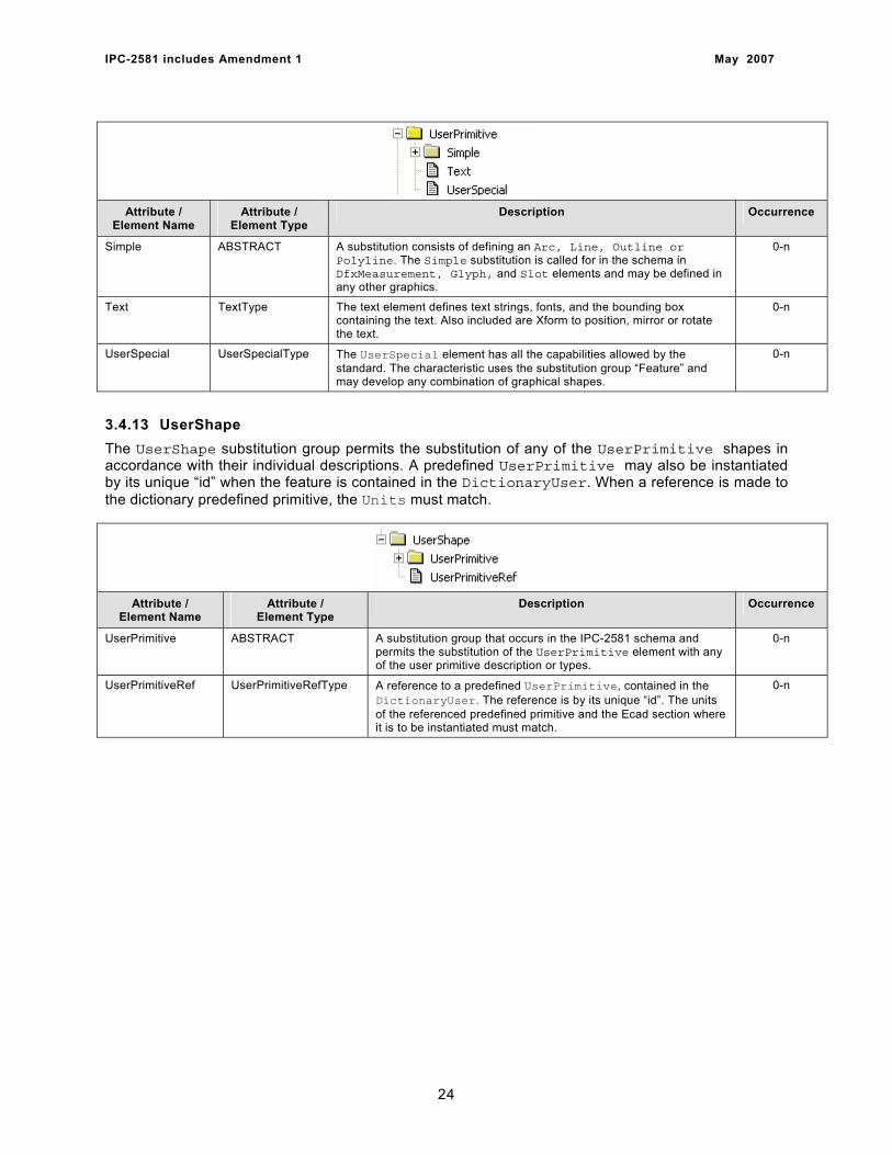
IPC-2581 includes Amendment 1 May 2007
Attribute / Element Name
Attribute / Element Type
Description Occurrence
Simple ABSTRACT A substitution consists of defining an Arc, Line, Outline or Polyline. The Simple substitution is called for in the schema in DfxMeasurement, Glyph, and Slot elements and may be defined in any other graphics.
0-n
Text TextType The text element defines text strings, fonts, and the bounding box containing the text. Also included are Xform to position, mirror or rotate the text.
0-n
UserSpecial UserSpecialType The UserSpecial element has all the capabilities allowed by the standard. The characteristic uses the substitution group “Feature” and may develop any combination of graphical shapes.
0-n
3.4.13 UserShape The UserShape substitution group permits the substitution of any of the UserPrimitive shapes in accordance with their individual descriptions. A predefined UserPrimitive may also be instantiated by its unique “id” when the feature is contained in the DictionaryUser. When a reference is made to the dictionary predefined primitive, the Units must match.
Attribute / Element Name
Attribute / Element Type
Description Occurrence
UserPrimitive ABSTRACT A substitution group that occurs in the IPC-2581 schema and permits the substitution of the UserPrimitive element with any of the user primitive description or types.
0-n
UserPrimitiveRef UserPrimitiveRefType A reference to a predefined UserPrimitive, contained in the DictionaryUser. The reference is by its unique “id”. The units of the referenced predefined primitive and the Ecad section where it is to be instantiated must match.
0-n
24
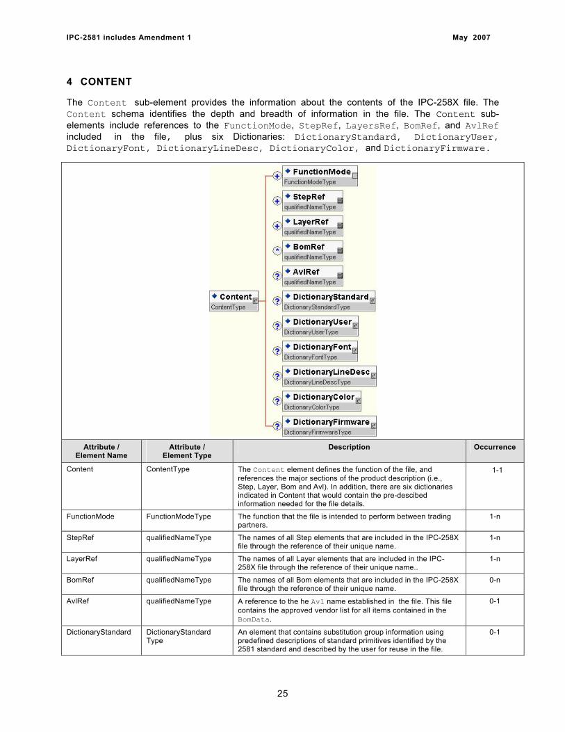
IPC-2581 includes Amendment 1 May 2007
4 CONTENT
The Content sub-element provides the information about the contents of the IPC-258X file. The Content schema identifies the depth and breadth of information in the file. The Content sub-elements include references to the FunctionMode, StepRef, LayersRef, BomRef, and AvlRef included in the file, plus six Dictionaries: DictionaryStandard, DictionaryUser, DictionaryFont, DictionaryLineDesc, DictionaryColor, and DictionaryFirmware.
Attribute / Element Name
Attribute / Element Type
Description Occurrence
Content ContentType The Content element defines the function of the file, and references the major sections of the product description (i.e., Step, Layer, Bom and Avl). In addition, there are six dictionaries indicated in Content that would contain the pre-descibed information needed for the file details.
1-1
FunctionMode FunctionModeType The function that the file is intended to perform between trading partners.
1-n
StepRef qualifiedNameType The names of all Step elements that are included in the IPC-258X file through the reference of their unique name.
1-n
LayerRef qualifiedNameType The names of all Layer elements that are included in the IPC-258X file through the reference of their unique name..
1-n
BomRef qualifiedNameType The names of all Bom elements that are included in the IPC-258X file through the reference of their unique name.
0-n
AvlRef qualifiedNameType A reference to the he Avl name established in the file. This file contains the approved vendor list for all items contained in the BomData.
0-1
DictionaryStandard DictionaryStandard Type
An element that contains substitution group information using predefined descriptions of standard primitives identified by the 2581 standard and described by the user for reuse in the file.
0-1
25
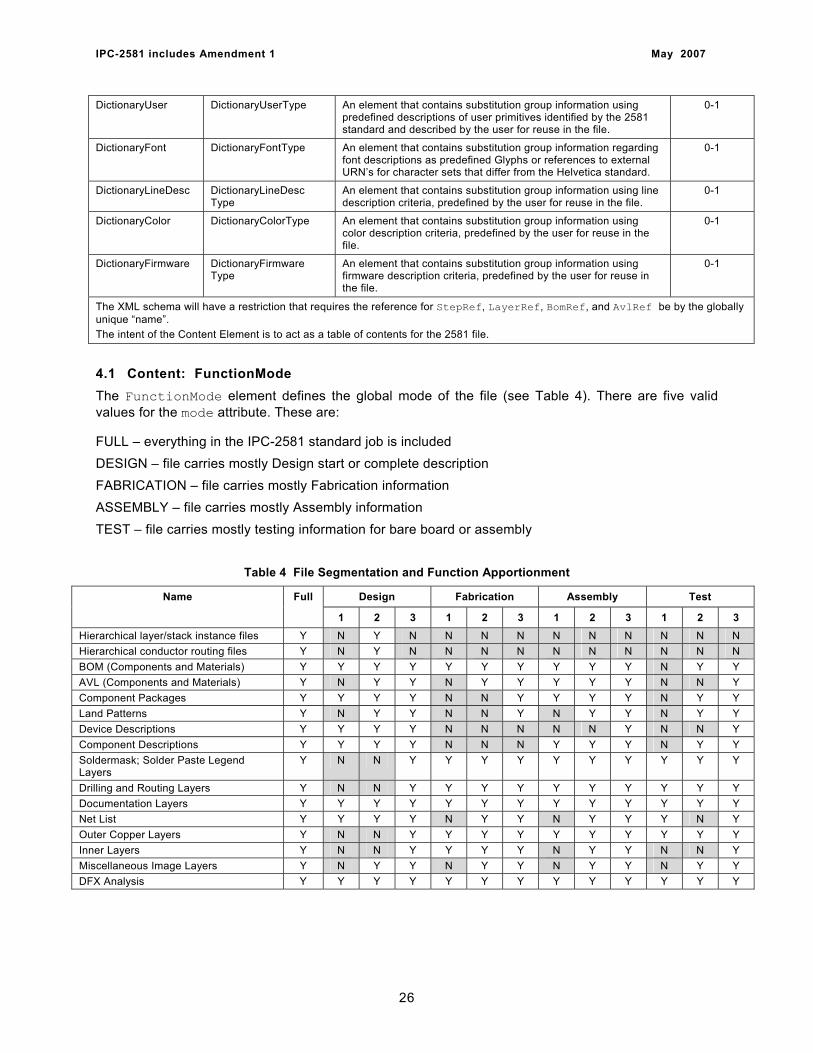
IPC-2581 includes Amendment 1 May 2007
DictionaryUser DictionaryUserType An element that contains substitution group information using predefined descriptions of user primitives identified by the 2581 standard and described by the user for reuse in the file.
0-1
DictionaryFont DictionaryFontType An element that contains substitution group information regarding font descriptions as predefined Glyphs or references to external URN’s for character sets that differ from the Helvetica standard.
0-1
DictionaryLineDesc DictionaryLineDesc Type
An element that contains substitution group information using line description criteria, predefined by the user for reuse in the file.
0-1
DictionaryColor DictionaryColorType An element that contains substitution group information using color description criteria, predefined by the user for reuse in the file.
0-1
DictionaryFirmware DictionaryFirmware Type
An element that contains substitution group information using firmware description criteria, predefined by the user for reuse in the file.
0-1
The XML schema will have a restriction that requires the reference for StepRef, LayerRef, BomRef, and AvlRef be by the globally unique “name”. The intent of the Content Element is to act as a table of contents for the 2581 file.
4.1 Content: FunctionMode The FunctionMode element defines the global mode of the file (see Table 4). There are five valid values for the mode attribute. These are:
FULL – everything in the IPC-2581 standard job is included DESIGN – file carries mostly Design start or complete description FABRICATION – file carries mostly Fabrication information ASSEMBLY – file carries mostly Assembly information TEST – file carries mostly testing information for bare board or assembly
Table 4 File Segmentation and Function Apportionment
Design Fabrication Assembly Test Name Full
1 2 3 1 2 3 1 2 3 1 2 3 Hierarchical layer/stack instance files Y N Y N N N N N N N N N N Hierarchical conductor routing files Y N Y N N N N N N N N N N BOM (Components and Materials) Y Y Y Y Y Y Y Y Y Y N Y Y AVL (Components and Materials) Y N Y Y N Y Y Y Y Y N N Y Component Packages Y Y Y Y N N Y Y Y Y N Y Y Land Patterns Y N Y Y N N Y N Y Y N Y Y Device Descriptions Y Y Y Y N N N N N Y N N Y Component Descriptions Y Y Y Y N N N Y Y Y N Y Y Soldermask; Solder Paste Legend Layers
Y N N Y Y Y Y Y Y Y Y Y Y
Drilling and Routing Layers Y N N Y Y Y Y Y Y Y Y Y Y Documentation Layers Y Y Y Y Y Y Y Y Y Y Y Y Y Net List Y Y Y Y N Y Y N Y Y Y N Y Outer Copper Layers Y N N Y Y Y Y Y Y Y Y Y Y Inner Layers Y N N Y Y Y Y N Y Y N N Y Miscellaneous Image Layers Y N Y Y N Y Y N Y Y N Y Y DFX Analysis Y Y Y Y Y Y Y Y Y Y Y Y Y
26
IPC-2581 includes Amendment 1 May 2007
Each FunctionMode has a specific purpose defined for the industry. The FunctionMode element has three attributes. The first is mode, which can be the enumerated strings of DESIGN, FABRICATION, ASSEMBLY, TEST and FULL. In many instances, the testing function is already included in fabrication and assembly modes consisting of bare board testing for fabrication, and in-circuit testing for assembly. Nevertheless, there are times when companies wish to outsource the testing activity. Therefore it is important to identify the various testing modes.
In order to define additional granularity, FunctionMode has a second attribute, level, that defines the data complexity needed for each of the mode condition. The attribute level is a positive integer however only the numbers 1, 2 or 3 are presently allowed since each mode has only three levels. When identifying FULL as the mode, the level should be set at 1. The levels encompass their own file details in order to identify that they are associated with an individual mode. Thus, the required file content for level 1 of the DESIGN mode is not the same as a level 1 for the ASSEMBLY mode.
The FunctionMode element has a third attribute. The attribute is comment which, as string data, permits the users of the 2581 file to enhance the FunctionMode descriptions with additional information.
4.1.1 FULL mode The FULL mode identifier incorporates a total of fifteen functions. Each function is represented and available in the file. The order of the details in the file is not significant as several elements may be used to address any given function. Hierarchical padstack and route information reflects original design intent that may be altered in the representation of the flattened fabrication data. For FABRICATION and ASSEMBLY, flattened data shall be used.
4.1.2 DESIGN mode The DESIGN mode consists of three levels of complexity. Each level performs a different function consisting of an original design starting from scratch to completed design that had already been converted to manufacturing data, or a completed design that is still in the CAD format structure. See IPC-2582 and IPC-2583 for sectional data descriptions.
4.1.3 FABRICATION mode The FABRICATION mode consists of three levels of complexity. Each level describes information in a layered format, from very simplistic data to that where the customer has dictated very specific materials and material stack-up structures. See IPC-2584 and IPC-2588 for sectional data descriptions.
4.1.4 ASSEMBLY mode The ASSEMBLY mode consists of three levels of complexity. Each level describes a concept of more complete information. The simplest level is mainly bill of material data as well as external copper layers. In its most complete form, the assembly information describes the component approved vendor listing for aliases and substitution in sufficient detail to ensure proper assembly. See IPC-2586 and IPC-2588 for sectional data descriptions.
4.1.5 TEST mode The Test mode consists of three levels of complexity. Each level describes a specific function for testing information that must be contained within a file. In its simplest mode, the data describes information to allow bare board testing. In its most complex mode, there is information on in-circuit test, impedance control, and dielectric withstanding voltage conditions. See IPC-2585 and IPC-2587 for sectional data descriptions.
4.2 Function levels The IPC-258X is limited to be organized as one of thirteen function levels. The level attribute, when associated with the mode attribute, defines the complexity and detail of the file content.
27
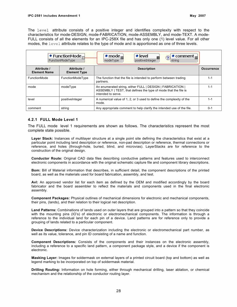
IPC-2581 includes Amendment 1 May 2007
The level attribute consists of a positive integer and identifies complexity with respect to the characteristics for mode-DESIGN, mode-FABRICATION, mode-ASSEMBLY, and mode-TEXT. A mode-FULL consists of all the elements for an IPC-258X file and has only one (1) level value. For all other modes, the level attribute relates to the type of mode and is apportioned as one of three levels.
Attribute / Element Name
Attribute / Element Type
Description Occurrence
FunctionMode FunctionModeType The function that the file is intended to perform between trading partners.
1-1
mode modeType An enumerated string, either FULL | DESIGN | FABRICATION | ASSEMBLY | TEST, that defines the type of mode that the file is intended to serve.
1-1
level positiveInteger A numerical value of 1, 2, or 3 used to define the complexity of the mode.
1-1
comment string Any appropriate comment to help clarify the intended use of the file. 0-1
4.2.1 FULL Mode Level 1 The FULL mode level 1 requirements are shown as follows. The characteristics represent the most complete state possible.
Layer Stack: Instances of multilayer structure at a single point site defining the characteristics that exist at a particular point including land description or reference, non-pad description or reference, thermal connections or reference, and holes (through-hole, buried, blind, and microvias). LayerStacks are for reference to the construction of the original design.
Conductor Route: Original CAD data files describing conductive patterns and features used to interconnect electronic components in accordance with the original schematic capture file and component library descriptions.
Bom: Bill of Material information that describes, in sufficient detail, the component descriptions of the printed board, as well as the materials used for board fabrication, assembly, and test.
Avl: An approved vendor list for each item as defined by the OEM and modified accordingly by the board fabricator and the board assembler to reflect the materials and components used in the final electronic assembly.
Component Packages: Physical outlines of mechanical dimensions for electronic and mechanical components, their pins, (lands), and their relation to their logical net description.
Land Patterns: Combinations of lands used on outer layers that are grouped into a pattern so that they coincide with the mounting pins (IO’s) of electronic or electromechanical components. The information is through a reference to the individual land for each pin of a device. Land patterns are for reference only to provide a grouping of lands related to a particular component.
Device Descriptions: Device characterization including the electronic or electromechanical part number, as well as its value, tolerance, and pin ID consisting of a name and function.
Component Descriptions: Consists of the components and their instances on the electronic assembly, including a reference to a specific land pattern, a component package style, and a device if the component is electronic.
Masking Layer: Images for soldermask on external layers of a printed circuit board (top and bottom) as well as legend marking to be incorporated on top of soldermask material.
Drilling Routing: Information on hole forming, either through mechanical drilling, laser ablation, or chemical mechanism and the relationship of the conductor routing layer.
28
IPC-2581 includes Amendment 1 May 2007
Documentation Layers: Information on the details for finishes, tolerances, and other details necessary to complete the full disclosure of the printed board structure and/or assembly.
Net List: A list of physical nets that includes the physical net points, the location, side, as well as additional information required for bare board electrical testing.
Outer Conductive: External copper geometries and features used for electronic probing or component attachment. They may be defined as positive or negative.
Inner Layers: Image description for innerlayers of multilayered PCB’s where the description indicates the conductive pattern as well as plated-through holes contained within a layerset. These characteristics are also used to describe embedded passive layers.
Image Layers: Miscellaneous image layers that may be extracted from the originating CAD system that provide supplementary details for either printed circuit board fabrication or printed circuit board assembly processes and testing.
Analysis: Any of the CAD data can have Design for Manufacturing processes run against it. The results of these are referenced in the Analysis element.
4.2.2 Design Levels The Design Level requirements have a variety of element combinations. Each combination is identified by its mode and level in combination. There are three Design Level descriptions starting with Design Level 1, Design Level 2 and Design Level 3. The following sections show the content of each of the three design levels. It should be noted that when the elements that represent the design mode are available in any of the fabrication or assembly file structures, the information should be treated as original input and reference and can be used for analysis and checking, however ASSEMBLY and FABRICATION elements take precedence.
4.2.2.1 Design Level 1 This level represents the original OEM design as was used to lay out a PCB from the design schematic, layout design rules, and component information. The characteristics represent designing from scratch, taking OEM input and developing the board. Design Level 1 requirements are shown as follows:
Bom: Bill of Material information that describes, in sufficient detail, the component descriptions of the printed board, as well as the materials used for board fabrication, assembly, and test.
Component Packages: Physical outlines of mechanical dimensions for electronic and mechanical components and their relation to their logical net description.
Device Descriptions: Device characterization including the electronic or electromechanical part number, as well as its value, tolerance, and pin ID consisting of a name and function.
Component Descriptions: Consists of the components and their instances on the electronic assembly, including a reference to a specific land pattern, a component package style, and a device if the component is electronic.
Documentation Layers: Information on the details for finishes, tolerances, and other details necessary to complete the full disclosure of the printed board structure and/or assembly.
Net List: A list of logical nets that includes the physical net points of the components, the location, side, as well as additional information required for bare board electrical testing.
Analysis: Any of the CAD data can have Design for Manufacturing processes run against it. The results of these are referenced in the Analysis element.
4.2.2.2 Design Level 2 This level provides information that is used to modify an existing design using the original CAD data information since the changes impact the electrical characteristics that should be maintained. The
29
IPC-2581 includes Amendment 1 May 2007
characteristics represent modifying a design where the Fabrication and Assembly file has been archived by the OEM. Design Level 2 requirements are shown as follows:
Layer Stack: Instances of multilayer structure at a single point site defining the characteristics that exist at a particular point including land description or reference, non-pad description or reference, thermal connections or reference, and holes (through-hole, buried, blind, and microvias). LayerStacks are for reference to the construction of the original design.
Conductor Route: Original CAD data files describing conductive patterns and features used to interconnect electronic components in accordance with the original schematic capture file and component library descriptions.
Bom: Bill of Material information that describes, in sufficient detail, the component descriptions of the printed board, as well as the materials used for board fabrication, assembly, and test.
Avl: An approved vendor list for each item as defined by the OEM and modified accordingly by the board fabricator and the board assembler to reflect the materials and components used in the final electronic assembly.
Component Packages: Physical outlines of mechanical dimensions for electronic and mechanical components, their pins, (lands), and their relation to their logical net description.
Land Patterns: Combinations of lands used on outer layers that are grouped into a pattern so that they coincide with the mounting pins (IO’s) of electronic or electromechanical components. The information is through a reference to the individual land for each pin of a device. Land patterns are for reference only to provide a grouping of lands related to a particular component.
Device Descriptions: Device characterization including the electronic or electromechanical part number, as well as its value, tolerance, and pin ID consisting of a name and function.
Component Descriptions: Consists of the components and their instances on the electronic assembly, including a reference to a specific land pattern, a component package style, and a device if the component is electronic.
Documentation Layers: Information on the details for finishes, tolerances, and other details necessary to complete the full disclosure of the printed board structure and/or assembly.
Net List: A list of physical nets that includes the physical net points, the location, side, as well as additional information required for bare board electrical testing.
Image Layers: Miscellaneous image layers that may be extracted from the originating CAD system that provide supplementary details for either printed circuit board fabrication or printed circuit board assembly processes and testing.
Analysis: Any of the CAD data can have Design for Manufacturing processes run against it. The results of these are referenced in the Analysis element.
4.2.2.3 Design Level 3 This information is used to modify an existing or archived design where the original hierarchical information was not maintained or may not be compatible with the design system. The characteristics represent modifying a design using the original CAD data information since the changes impact the electrical characteristics that should be maintained. Design Level 3 requirements are shown as follows:
Bom: Bill of Material information that describes, in sufficient detail, the component descriptions of the printed board, as well as the materials used for board fabrication, assembly, and test.
Avl: An approved vendor list for each item as defined by the OEM and modified accordingly by the board fabricator and the board assembler to reflect the materials and components used in the final electronic assembly.
Component Packages: Physical outlines of mechanical dimensions for electronic and mechanical components, their pins, (lands), and their relation to their logical net description.
30
IPC-2581 includes Amendment 1 May 2007
Land Patterns: Combinations of lands used on outer layers that are grouped into a pattern so that they coincide with the mounting pins (IO’s) of electronic or electromechanical components. The information is through a reference to the individual land for each pin of a device. Land patterns are for reference only to provide a grouping of lands related to a particular component.
Device Descriptions: Device characterization including the electronic or electromechanical part number, as well as its value, tolerance, and pin ID consisting of a name and function.
Component Descriptions: Consists of the components and their instances on the electronic assembly, including a reference to a specific land pattern, a component package style, and a device if the component is electronic.
Masking Layer: Images for soldermask on external layers of a printed circuit board (top and bottom) as well as legend marking to be incorporated on top of soldermask material.
Drilling Routing: Information on hole forming, either through mechanical drilling, laser ablation, or chemical mechanism and the relationship of the conductor routing layer.
Documentation Layers: Information on the details for finishes, tolerances, and other details necessary to complete the full disclosure of the printed board structure and/or assembly.
Net List: A list of physical nets that includes the physical net points, the location, side, as well as additional information required for bare board electrical testing.
Outer Conductive: External copper geometries and features used for electronic probing or component attachment. They may be defined as positive or negative.
Inner Layers: Image description for innerlayers of multilayered PCB’s where the description indicates the conductive pattern as well as plated-through holes contained within a layerset. These characteristics are also used to describe embedded passive layers.
Image Layers: Miscellaneous image layers that may be extracted from the originating CAD system that provide supplementary details for either printed circuit board fabrication or printed circuit board assembly processes and testing.
Analysis: Any of the CAD data can have Design for Manufacturing processes run against it. The results of these are referenced in the Analysis element.
4.2.3 Fabrication Levels The Fabrication Level requirements have a variety of element combinations. Each combination is identified by its mode and level in combination. There are three Fabrication Level descriptions starting with Fabrication Level 1, Fabrication Level 2 and Fabrication Level 3. The following sections show the content of each of the three fabrication levels.
4.2.3.1 Fabrication Level 1 This information represents single, double-sided, or multilayer PCB graphical data. There is no electrical connectivity or performance data included. This level replaces PCB fabrication Gerber data. This level presents the fabrication print notes and material construction information in a machine-readable ASCII file format. The level is for build to documentation instructions. Electrical testing is derived from the conductive images. The characteristics represent single or double sided boards, built to documentation. Fabrication Level 1 requirements are shown as follows:
Bom: Bill of Material information that describes, in sufficient detail, the component descriptions of the printed board, as well as the materials used for board fabrication, assembly, and test.
Masking Layer: Images for soldermask on external layers of a printed circuit board (top and bottom) as well as legend marking to be incorporated on top of soldermask material.
Drilling Routing: Information on hole forming, either through mechanical drilling, laser ablation, or chemical mechanism and the relationship of the conductor routing layer.
31
IPC-2581 includes Amendment 1 May 2007
Documentation Layers: Information on the details for finishes, tolerances, and other details necessary to complete the full disclosure of the printed board structure and/or assembly.
Outer Conductive: External copper geometries and features used for electronic probing or component attachment. They may be defined as positive or negative.
Inner Layers: Image description for innerlayers of multilayered PCB’s where the description indicates the conductive pattern as well as plated-through holes contained within a layerset. These characteristics are also used to describe embedded passive layers.
Analysis: Any of the CAD data can have Design for Manufacturing processes run against it. The results of these are referenced in the Analysis element.
4.2.3.2 Fabrication Level 2 This information represents single, double-sided, or multilayer PCB’s where electrical connectivity or performance data is included. This replaces the PCB Gerber and IPC-D-356A. This level presents the fabrication print notes and material construction information in a machine-readable ASCII file format. The boards defined may include buried and blind vias with electrical opens and shorts testing and complete stack up definition. Fabrication Level 2 requirements are shown as follows:
Bom: Bill of Material information that describes, in sufficient detail, the component descriptions of the printed board, as well as the materials used for board fabrication, assembly, and test.
Avl: An approved vendor list for each item as defined by the OEM and modified accordingly by the board fabricator and the board assembler to reflect the materials and components used in the final electronic assembly.
Masking Layer: Images for soldermask on external layers of a printed circuit board (top and bottom) as well as legend marking to be incorporated on top of soldermask material.
Drilling Routing: Information on hole forming, either through mechanical drilling, laser ablation, or chemical mechanism and the relationship of the conductor routing layer.
Documentation Layers: Information on the details for finishes, tolerances, and other details necessary to complete the full disclosure of the printed board structure and/or assembly.
Net List: A list of physical nets that includes the physical net points, the location, side, as well as additional information required for bare board electrical testing.
Outer Conductive: External copper geometries and features used for electronic probing or component attachment. They may be defined as positive or negative.
Inner Layers: Image description for innerlayers of multilayered PCB’s where the description indicates the conductive pattern as well as plated-through holes contained within a layerset. These characteristics are also used to describe embedded passive layers.
Image Layers: Miscellaneous image layers that may be extracted from the originating CAD system that provide supplementary details for either printed circuit board fabrication or printed circuit board assembly processes and testing.
Analysis: Any of the CAD data can have Design for Manufacturing processes run against it. The results of these are referenced in the Analysis element.
4.2.3.3 Fabrication Level 3 This information represents single, double-sided, or multilayer PCB’s where electrical connectivity, performance data, and embedded passive information is included. This file level replaces the existing PCB fabrication Gerber and IPC-D-356A data. This level presents the fabrication print notes and material construction information in a machine-readable ASCII file format. These descriptions represent complex printed boards intended to perform a circuit function. Also included is a complete description of core, prepreg and sometimes reinforcement. Fabrication Level 3 requirements are shown as follows:
32

IPC-2581 includes Amendment 1 May 2007
Bom: Bill of Material information that describes, in sufficient detail, the component descriptions of the printed board, as well as the materials used for board fabrication, assembly, and test.
Avl: An approved vendor list for each item as defined by the OEM and modified accordingly by the board fabricator and the board assembler to reflect the materials and components used in the final electronic assembly.
Component Packages: Physical outlines of mechanical dimensions for electronic and mechanical components and their relation to their logical net description.
Land Patterns: Combinations of lands used on outer layers that are grouped into a pattern so that they coincide with the mounting pins (IO’s) of electronic or electromechanical components. The information is through a reference to the individual land for each pin of a device. Land patterns are for reference only to provide a grouping of lands related to a particular component.
Masking Layer: Images for soldermask on external layers of a printed circuit board (top and bottom) as well as legend marking to be incorporated on top of soldermask material.
Drilling Routing: Information on hole forming, either through mechanical drilling, laser ablation, or chemical mechanism and the relationship of the conductor routing layer.
Documentation Layers: Information on the details for finishes, tolerances, and other details necessary to complete the full disclosure of the printed board structure and/or assembly.
Net List: A list of physical nets that includes the physical net points, the location, side, as well as additional information required for bare board electrical testing.
Outer Conductive: External copper geometries and features used for electronic probing or component attachment. They may be defined as positive or negative.
Inner Layers: Image description for innerlayers of multilayered PCB’s where the description indicates the conductive pattern as well as plated-through holes contained within a layerset. These characteristics are also used to describe embedded passive (resistive or capacitive) material layers.
Image Layers: Miscellaneous image layers that may be extracted from the originating CAD system that provide supplementary details for either printed circuit board fabrication or printed circuit board assembly processes and testing.
Analysis: Any of the CAD data can have Design for Manufacturing processes run against it. The results of these are referenced in the Analysis element.
4.2.4 Assembly Levels The Assembly Level requirements have a variety of element combinations. Each combination is identified by its mode and level in combination. There are three Assembly Level descriptions starting with Assembly Level 1, Assembly Level 2 and Assemblyy Level 3. The following sections show the content of each of the three assembly levels.
4.2.4.1 Assembly Level 1 This information represents pure assembly. There is no Design for Manufacturing (DFM) analysis of the bare board only assembly functions. Parts are provided on a consignment basis, however an Approved Vendors List (AVL) is still required that includes the part number of parts in the consignment. There is no analysis of the data to improve the design. There are no added value services. The requirements are to build to print. Assembly Level 1 requirements are shown as follows:
Bom: Bill of Material information that describes, in sufficient detail, the component descriptions of the printed board, assembly, and test information.
Avl: An approved vendor list for each item as defined by the OEM and modified accordingly by the board fabricator and the board assembler to reflect the materials and components used in the final electronic assembly.
33
IPC-2581 includes Amendment 1 May 2007
Component Packages: Physical outlines of mechanical dimensions for electronic and mechanical components, their pins, (lands), and their relation to their logical net description.
Component Descriptions: Consists of the components and their instances on the electronic assembly, including a reference to a component package style, and a Bom item.
Masking Layer: Images for soldermask on external layers of a printed circuit board (top and bottom) as well as legend marking to be incorporated on top of soldermask material.
Drilling Routing: Information on hole forming, either through mechanical drilling, laser ablation, or chemical mechanism and the relationship of the conductor routing layer.
Documentation Layers: Information on the details for finishes, tolerances, and other details necessary to complete the full disclosure of the printed board structure and/or assembly.
Outer Conductive: External copper geometries and features used for electronic probing or component attachment. They may be defined as positive or negative.
Analysis: Any of the CAD data can have Design for Manufacturing processes run against it. The results of these are referenced in the Analysis element.
4.2.4.2 Assembly Level 2 The information provided represents assemblies that are to be built to print. Parts are procured by Electronic Manufacturing Services (EMS) companies. There is limited DFM analysis, Automated Optical Inspection (AOI), and Flying probe testing. Assembly Level 2 requirements are shown as follows:
Bom: Bill of Material information that describes, in sufficient detail, the component descriptions of the printed board, as well as the materials used for board fabrication, assembly, and test.
Avl: An approved vendor list for each item as defined by the OEM and modified accordingly by the board fabricator and the board assembler to reflect the materials and components used in the final electronic assembly.
Component Packages: Physical outlines of mechanical dimensions for electronic and mechanical components, their pins, (lands), and their relation to their logical net description.
Land Patterns: Combinations of lands used on outer layers that are grouped into a pattern so that they coincide with the mounting pins (IO’s) of electronic or electromechanical components. The information is through a reference to the individual land for each pin of a device. Land patterns are for reference only to provide a grouping of lands related to a particular component.
Component Descriptions: Consists of the components and their instances on the electronic assembly, including a reference to a component package style, and a Bom item.
Masking Layer: Images for soldermask on external layers of a printed circuit board (top and bottom) as well as legend marking to be incorporated on top of soldermask material.
Drilling Routing: Information on hole forming, either through mechanical drilling, laser ablation, or chemical mechanism and the relationship of the conductor routing layer.
Documentation Layers: Information on the details for finishes, tolerances, and other details necessary to complete the full disclosure of the printed board structure and/or assembly.
Net List: A list of physical nets that includes the physical net points, the location, side, as well as additional information required for bare board electrical testing.
Outer Conductive: External copper geometries and features used for electronic probing or component attachment. They may be defined as positive or negative.
Inner Layers: Image description for innerlayers of multilayered PCB’s where the description indicates the conductive pattern as well as plated-through holes contained within a layerset. These characteristics are also used to describe embedded passive layers.
34

IPC-2581 includes Amendment 1 May 2007
Image Layers: Miscellaneous image layers that may be extracted from the originating CAD system that provide supplementary details for either printed circuit board fabrication or printed circuit board assembly processes and testing.
Analysis: Any of the CAD data can have Design for Manufacturing processes run against it. The results of these are referenced in the Analysis element.
4.2.4.3 Assembly Level 3 This level of information represents a full service assembly process. This includes full Design for Excellence (DFX) and customer feed back. Procurement of parts is required as well as an analysis of component substitution. Customer contact provides design improvement recommendations. Full testing, including in-circuit, automatic optical inspection (AOI), Automatic X-ray Inspection (AXI), functional testing and some stress or burn-in testing is a part of this level. DFA can include assignment of parts to specific machines. Assembly Level 3 requirements are shown as follows.
Bom: Bill of Material information that describes, in sufficient detail, the component descriptions of the printed board, as well as the materials used for board fabrication, assembly, and test.
Avl: An approved vendor list for each item as defined by the OEM and modified accordingly by the board fabricator and the board assembler to reflect the materials and components used in the final electronic assembly.
Component Packages: Physical outlines of mechanical dimensions for electronic and mechanical components, their pins, (lands), and their relation to their logical net description.
Land Patterns: Combinations of lands used on outer layers that are grouped into a pattern so that they coincide with the mounting pins (IO’s) of electronic or electromechanical components. The information is through a reference to the individual land for each pin of a device. Land patterns are for reference only to provide a grouping of lands related to a particular component.
Device Descriptions: Device characterization including the electronic or electromechanical part number, as well as its value, tolerance, and pin ID consisting of a name and function.
Component Descriptions: Consists of the components and their instances on the electronic assembly, including a reference to a component package style, and a Bom item.
Masking Layer: Images for soldermask on external layers of a printed circuit board (top and bottom) as well as legend marking to be incorporated on top of soldermask material.
Drilling Routing: Information on hole forming, either through mechanical drilling, laser ablation, or chemical mechanism and the relationship of the conductor routing layer.
Documentation Layers: Information on the details for finishes, tolerances, and other details necessary to complete the full disclosure of the printed board structure and/or assembly.
Net List: A list of physical nets that includes the physical net points, the location, side, as well as additional information required for bare board electrical testing.
Outer Conductive: External copper geometries and features used for electronic probing or component attachment. They may be defined as positive or negative.
Inner Layers: Image description for innerlayers of multilayered PCB’s where the description indicates the conductive pattern as well as plated-through holes contained within a layerset. These characteristics are also used to describe embedded passive layers.
Image Layers: Miscellaneous image layers that may be extracted from the originating CAD system that provide supplementary details for either printed circuit board fabrication or printed circuit board assembly processes and testing.
Analysis: Any of the CAD data can have Design for Manufacturing processes run against it. The results of these are referenced in the Analysis element.
35
IPC-2581 includes Amendment 1 May 2007
4.2.5 Test Levels TheTest Level requirements have a variety of element combinations. Each combination is identified by its mode and level in combination. There are three Test Level descriptions starting with Test Level 1, Test Level 2 and Test Level 3. The following sections show the content of each of the three test levels.
4.2.5.1 Test Level 1 This information provides testing of the bare board only. It includes opens and shorts, impedance control and dielectric withstanding voltage testing. Test Level 1 requirements are shown as follows:
Masking Layer: Images for soldermask on external layers of a printed circuit board (top and bottom) as well as legend marking to be incorporated on top of soldermask material.
Drilling Routing: Information on hole forming, either through mechanical drilling, laser ablation, or chemical mechanism and the relationship of the conductor routing layer.
Documentation Layers: Information on the details for finishes, tolerances, and other details necessary to complete the full disclosure of the printed board structure and/or assembly.
Net List: A list of physical nets that includes the physical net points, the location, side, as well as additional information required for bare board electrical testing.
Outer Conductive: External copper geometries and features used for electronic probing or component attachment. They may be defined as positive or negative.
Analysis: Any of the CAD data can have Design for Manufacturing processes run against it. The results of these are referenced in the Analysis element.
4.2.5.2 Test Level 2 The information provided includes capability for inspection, manual or using automated equipment such as AOI and AXI. It does not include electrical testing. Test Level 2 requirements are shown as follows:
Bom: Bill of Material information that describes, in sufficient detail, the component descriptions of the printed board, as well as the materials used for board fabrication, assembly, and test.
Component Packages: Physical outlines of mechanical dimensions for electronic and mechanical components, their pins, (lands), and their relation to their logical net description.
Land Patterns: Combinations of lands used on outer layers that are grouped into a pattern so that they coincide with the mounting pins (IO’s) of electronic or electromechanical components. The information is through a reference to the individual land for each pin of a device. Land patterns are for reference only to provide a grouping of lands related to a particular component.
Component Descriptions: Consists of the components and their instances on the electronic assembly, including a reference to a component package style, and a Bom item.
Masking Layer: Images for soldermask on external layers of a printed circuit board (top and bottom) as well as legend marking to be incorporated on top of soldermask material.
Drilling Routing: Information on hole forming, either through mechanical drilling, laser ablation, or chemical mechanism and the relationship of the conductor routing layer.
Documentation Layers: Information on the details for finishes, tolerances, and other details necessary to complete the full disclosure of the printed board structure and/or assembly.
Outer Conductive: External copper geometries and features used for electronic probing or component attachment. They may be defined as positive or negative.
Image Layers: Miscellaneous image layers that may be extracted from the originating CAD system that provide supplementary details for either printed circuit board fabrication or printed circuit board assembly processes and testing.
36

IPC-2581 includes Amendment 1 May 2007
Analysis: Any of the CAD data can have Design for Manufacturing processes run against it. The results of these are referenced in the Analysis element.
4.2.5.3 Test Level 3 The information available is for full electrical testing. It includes in-circuit as well as functional testing requirements and boundary scan (self test) analysis. Test Level 3 requirements are shown as follows:
Bom: Bill of Material information that describes, in sufficient detail, the component descriptions of the printed board, as well as the materials used for board fabrication, assembly, and test.
Avl: An approved vendor list for each item as defined by the OEM and modified accordingly by the board fabricator and the board assembler to reflect the materials and components used in the final electronic assembly.
Component Packages: Physical outlines of mechanical dimensions for electronic and mechanical components, their pins, (lands), and their relation to their logical net description.
Land Patterns: Combinations of lands used on outer layers that are grouped into a pattern so that they coincide with the mounting pins (IO’s) of electronic or electromechanical components. The information is through a reference to the individual land for each pin of a device. Land patterns are for reference only to provide a grouping of lands related to a particular component.
Device Descriptions: Device characterization including the electronic or electromechanical part number, as well as its value, tolerance, and pin ID consisting of a name and function.
Component Descriptions: Consists of the components and their instances on the electronic assembly, including a reference to a component package style, and a Bom item.
Masking Layer: Images for soldermask on external layers of a printed circuit board (top and bottom) as well as legend marking to be incorporated on top of soldermask material.
Drilling Routing: Information on hole forming, either through mechanical drilling, laser ablation, or chemical mechanism and the relationship of the conductor routing layer.
Documentation Layers: Information on the details for finishes, tolerances, and other details necessary to complete the full disclosure of the printed board structure and/or assembly.
Net List: A list of physical nets that includes the physical net points, the location, side, as well as additional information required for bare board electrical testing.
Outer Conductive: External copper geometries and features used for electronic probing or component attachment. They may be defined as positive or negative.
Inner Layers: Image description for innerlayers of multilayered PCB’s where the description indicates the conductive pattern as well as plated-through holes contained within a layerset. These characteristics are also used to describe embedded passive layers.
Image Layers: Miscellaneous image layers that may be extracted from the originating CAD system that provide supplementary details for either printed circuit board fabrication or printed circuit board assembly processes and testing.
Analysis: Any of the CAD data can have Design for Manufacturing processes run against it. The results of these are referenced in the Analysis element.
4.3 Content: StepRef The reference to the names of all Step elements used in the description of the Printed Circuit Assembly (PCA), the unpopulated board or other related information (eg., documentation). In manufacturing, this basic Step is often step and repeated (nested) inside a larger step (called array, or sub-panel). This array step can be further nested into another step (called a production panel). The
37
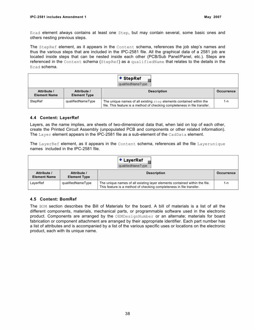
IPC-2581 includes Amendment 1 May 2007
Ecad element always contains at least one Step, but may contain several, some basic ones and others nesting previous steps.
The StepRef element, as it appears in the Content schema, references the job step’s names and thus the various steps that are included in the IPC-2581 file. All the graphical data of a 2581 job are located inside steps that can be nested inside each other (PCB/Sub Panel/Panel, etc.). Steps are referenced in the Content schema (StepRef) as a qualifiedName that relates to the details in the Ecad schema.
Attribute / Element Name
Attribute / Element Type
Description Occurrence
StepRef qualifiedNameType The unique names of all existing step elements contained within the file. This feature is a method of checking completeness in file transfer.
1-n
4.4 Content: LayerRef Layers, as the name implies, are sheets of two-dimensional data that, when laid on top of each other, create the Printed Circuit Assembly (unpopulated PCB and components or other related information). The Layer element appears in the IPC-2581 file as a sub-element of the CadData element.
The LayerRef element, as it appears in the Content schema, references all the file Layerunique names included in the IPC-2581 file.
Attribute / Element Name
Attribute / Element Type
Description Occurrence
LayerRef qualifiedNameType The unique names of all existing layer elements contained within the file. This feature is a method of checking completeness in file transfer.
1-n
4.5 Content: BomRef The BOM section describes the Bill of Materials for the board. A bill of materials is a list of all the different components, materials, mechanical parts, or programmable software used in the electronic product. Components are arranged by the OEMDesignNumber or an alternate; materials for board fabrication or component attachment are arranged by their appropriate identifier. Each part number has a list of attributes and is accompanied by a list of the various specific uses or locations on the electronic product, each with its unique name.
38
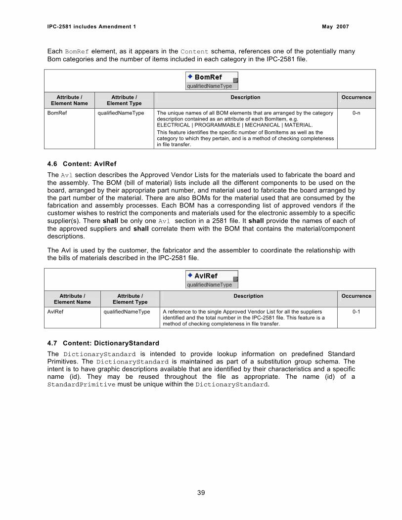
IPC-2581 includes Amendment 1 May 2007
Each BomRef element, as it appears in the Content schema, references one of the potentially many Bom categories and the number of items included in each category in the IPC-2581 file.
Attribute / Element Name
Attribute / Element Type
Description Occurrence
BomRef qualifiedNameType The unique names of all BOM elements that are arranged by the category description contained as an attribute of each BomItem, e.g. ELECTRICAL | PROGRAMMABLE | MECHANICAL | MATERIAL. This feature identifies the specific number of BomItems as well as the category to which they pertain, and is a method of checking completeness in file transfer.
0-n
4.6 Content: AvlRef The Avl section describes the Approved Vendor Lists for the materials used to fabricate the board and the assembly. The BOM (bill of material) lists include all the different components to be used on the board, arranged by their appropriate part number, and material used to fabricate the board arranged by the part number of the material. There are also BOMs for the material used that are consumed by the fabrication and assembly processes. Each BOM has a corresponding list of approved vendors if the customer wishes to restrict the components and materials used for the electronic assembly to a specific supplier(s). There shall be only one Avl section in a 2581 file. It shall provide the names of each of the approved suppliers and shall correlate them with the BOM that contains the material/component descriptions.
The Avl is used by the customer, the fabricator and the assembler to coordinate the relationship with the bills of materials described in the IPC-2581 file.
Attribute / Element Name
Attribute / Element Type
Description Occurrence
AvlRef qualifiedNameType A reference to the single Approved Vendor List for all the suppliers identified and the total number in the IPC-2581 file. This feature is a method of checking completeness in file transfer.
0-1
4.7 Content: DictionaryStandard The DictionaryStandard is intended to provide lookup information on predefined Standard Primitives. The DictionaryStandard is maintained as part of a substitution group schema. The intent is to have graphic descriptions available that are identified by their characteristics and a specific name (id). They may be reused throughout the file as appropriate. The name (id) of a StandardPrimitive must be unique within the DictionaryStandard.
39

IPC-2581 includes Amendment 1 May 2007
Attribute / Element Name
Attribute / Element Type
Description Occurrence
DictionaryStandard DictionaryStandard Type
An element that contains substitution group information using predefined descriptions of standard primitives identified by the 2581 standard and described by the user for reuse in the file.
0-1
units unitsType An enumerated string that may be one of the following: MILLIMETER | MICRON | INCH.
1-1
EntryStandard EntryStandardType An element that establishes the individual characteristic associated with a StandardPrimitive substitution shape that has been identified by the user of the IPC-2581 file.
0-n
Id qualifiedNameType The unique qualified name description assigned as an id for any StandardPrimitive for XML schema substitution.
1-1
StandardPrimitive ABSTRACT Any standard primitive that is part of the substitution group that permits the substitution of the StandardShape element.
1-n
The organization of the DictionaryStandard is accomplished in accordance with the substitution group description criteria. The StandardPrimitive description may be any of sixteen standard shapes according to the specific characteristics identified in the following paragraphs. The StandardPrimitiveRef function is used in the body of the 2581 file when a specific StandardPrimitive has been predefined, assigned a name, and the unique “id” is referenced in the file. This feature permits the use of either a predefined StandardPrimitive, or defining the details of a StandardPrimitive within the file. The description in the file must contain all the features of a particular primitive shape under the rules of the particular shape definition.
4.7.1 StandardPrimitive: Butterfly A Butterfly is a StandardPrimitive shape that may have the external periphery be either round or square with two quadrants of the Cartesian coordinate system removed (0 to 90° and 180 to 270°). The round shape is defined by its diameter; the square shape is defined by an equal side dimension. The Butterfly is positioned by its point of origin, which is at the center of the Butterfly.
Attribute / Element Name
Attribute / Element Type
Description Occurrence
Butterfly ButterflyType A primitive shape (either ROUND or SQUARE) that has two quadrants of the Cartesian coordinate system removed (0 to 90° and 180 to 270°).
1-1
shape butterflyShapeType The inner and outer shapes are one of ROUND or SQUARE: ROUND: The inner and outer shapes are like circleDef. SQUARE: The inner and outer shapes are like RectCenterDef with height and width of each shape being equal.
1-1
diameter nonNegativeDouble Type
The diameter applies to the circular butterfly and is the outer boundary of the butterfly.
0-1
40
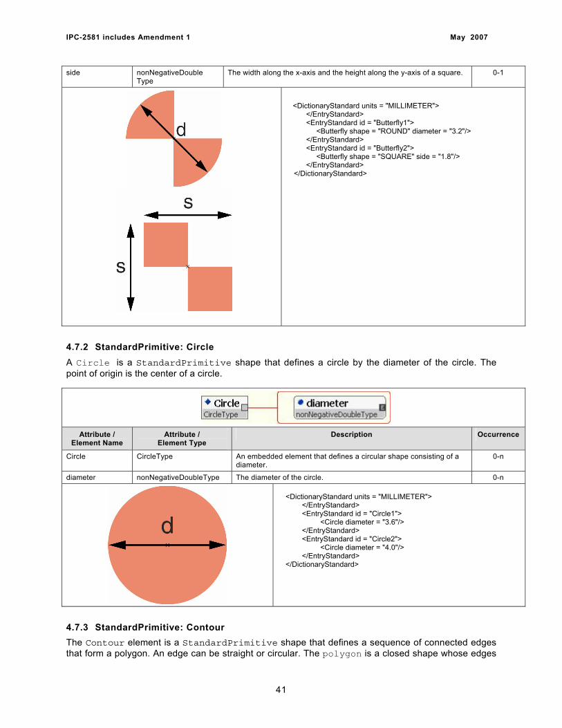
IPC-2581 includes Amendment 1 May 2007
side nonNegativeDouble Type
The width along the x-axis and the height along the y-axis of a square. 0-1
<DictionaryStandard units = "MILLIMETER"> </EntryStandard> <EntryStandard id = "Butterfly1"> <Butterfly shape = "ROUND" diameter = "3.2"/> </EntryStandard> <EntryStandard id = "Butterfly2"> <Butterfly shape = "SQUARE" side = "1.8"/> </EntryStandard> </DictionaryStandard>
4.7.2 StandardPrimitive: Circle A Circle is a StandardPrimitive shape that defines a circle by the diameter of the circle. The point of origin is the center of a circle.
Attribute / Element Name
Attribute / Element Type
Description Occurrence
Circle CircleType An embedded element that defines a circular shape consisting of a diameter.
0-n
diameter nonNegativeDoubleType The diameter of the circle. 0-n
<DictionaryStandard units = "MILLIMETER"> </EntryStandard> <EntryStandard id = "Circle1"> <Circle diameter = "3.6"/> </EntryStandard> <EntryStandard id = "Circle2"> <Circle diameter = "4.0"/> </EntryStandard> </DictionaryStandard>
4.7.3 StandardPrimitive: Contour The Contour element is a StandardPrimitive shape that defines a sequence of connected edges that form a polygon. An edge can be straight or circular. The polygon is a closed shape whose edges
41
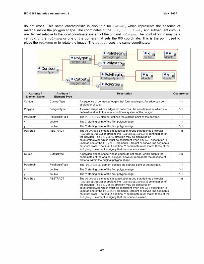
IPC-2581 includes Amendment 1 May 2007
do not cross. This same characteristic is also true for cutout, which represents the absence of material inside the polygon shape. The coordinates of the polygon, cutout, and subsequent cutouts are defined relative to the local coordinate system of the original polygon. The point of origin may be a centroid of the polygon or one of the corners that sets the 0/0 coordinate. This is the point used to place the polygon or to rotate the image. The cutout uses the same coordinates.
Attribute / Element Name
Attribute / Element Type
Description Occurrence
Contour ContourType A sequence of connected edges that form a polygon. An edge can be straight or circular.
1-1
Polygon PolygonType A closed shape whose edges do not cross, the coordinates of which are defined relative to the local coordinate system of the polygon.
1-1
PolyBegin PolyBeginType The PolyBegin element defines the starting point of the polygon. 1-1
x double The X starting point of the first polygon edge. 1-1
y double The Y starting point of the first polygon edge. 1-1
PolyStep ABSTRACT The PolyStep element is a substitution group that defines a circular (PolyStepCurve) or straight line (PolyStepSegment) continuation of the polygon. The polystep direction may be clockwise or counterclockwise which must be consistent when any Arc description is used as one of the PolyStep elements. Straight or curved line segments must not cross. The final X and final Y coordinate must match those of the PolyBegin element to signify that the shape is closed.
1-n
Cutout CutoutType A polygon closed shape whose edges do not cross, which adopts the coordinates of the original polygon, however represents the absence of material within the original polygon shape.
0-n
PolyBegin PolyBeginType The PolyBegin element defines the starting point of the polygon. 1-1
x double The X starting point of the first polygon edge. 1-1
y double The Y starting point of the first polygon edge. 1-1
PolyStep ABSTRACT The PolyStep element is a substitution group that defines a circular (PolyStepCurve) or straight line (PolyStepSegment) continuation of the polygon. The polystep direction may be clockwise or counterclockwise which must be consistent when any Arc description is used as one of the PolyStep elements. Straight or curved line segments must not cross. The final X and final Y coordinate must match those of the PolyBegin element to signify that the shape is closed.
1-n
42
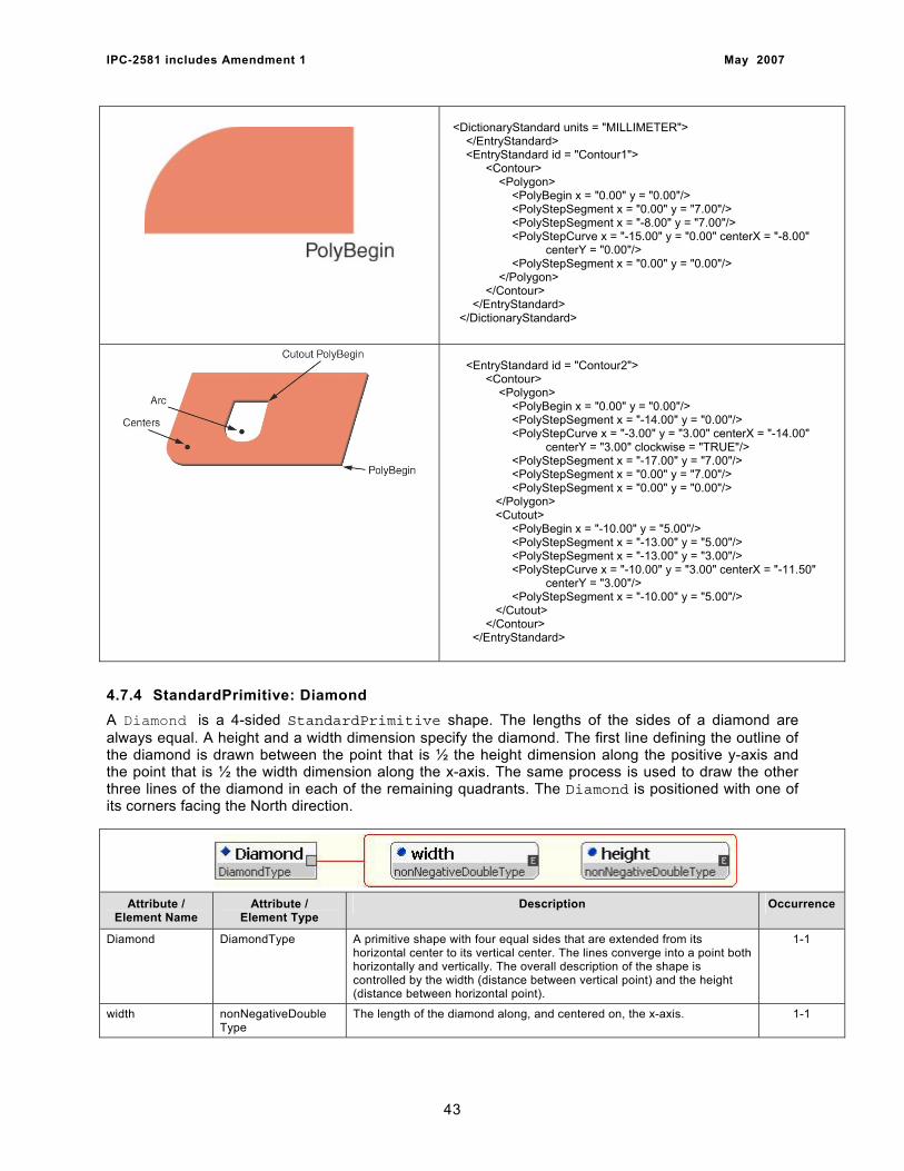
IPC-2581 includes Amendment 1 May 2007
<DictionaryStandard units = "MILLIMETER"> </EntryStandard> <EntryStandard id = "Contour1"> <Contour> <Polygon> <PolyBegin x = "0.00" y = "0.00"/> <PolyStepSegment x = "0.00" y = "7.00"/> <PolyStepSegment x = "-8.00" y = "7.00"/> <PolyStepCurve x = "-15.00" y = "0.00" centerX = "-8.00" centerY = "0.00"/> <PolyStepSegment x = "0.00" y = "0.00"/> </Polygon> </Contour> </EntryStandard> </DictionaryStandard>
<EntryStandard id = "Contour2"> <Contour> <Polygon> <PolyBegin x = "0.00" y = "0.00"/> <PolyStepSegment x = "-14.00" y = "0.00"/> <PolyStepCurve x = "-3.00" y = "3.00" centerX = "-14.00" centerY = "3.00" clockwise = "TRUE"/> <PolyStepSegment x = "-17.00" y = "7.00"/> <PolyStepSegment x = "0.00" y = "7.00"/> <PolyStepSegment x = "0.00" y = "0.00"/> </Polygon> <Cutout> <PolyBegin x = "-10.00" y = "5.00"/> <PolyStepSegment x = "-13.00" y = "5.00"/> <PolyStepSegment x = "-13.00" y = "3.00"/> <PolyStepCurve x = "-10.00" y = "3.00" centerX = "-11.50" centerY = "3.00"/> <PolyStepSegment x = "-10.00" y = "5.00"/> </Cutout> </Contour> </EntryStandard>
4.7.4 StandardPrimitive: Diamond A Diamond is a 4-sided StandardPrimitive shape. The lengths of the sides of a diamond are always equal. A height and a width dimension specify the diamond. The first line defining the outline of the diamond is drawn between the point that is ½ the height dimension along the positive y-axis and the point that is ½ the width dimension along the x-axis. The same process is used to draw the other three lines of the diamond in each of the remaining quadrants. The Diamond is positioned with one of its corners facing the North direction.
Attribute / Element Name
Attribute / Element Type
Description Occurrence
Diamond DiamondType A primitive shape with four equal sides that are extended from its horizontal center to its vertical center. The lines converge into a point both horizontally and vertically. The overall description of the shape is controlled by the width (distance between vertical point) and the height (distance between horizontal point).
1-1
width nonNegativeDouble Type
The length of the diamond along, and centered on, the x-axis. 1-1
43
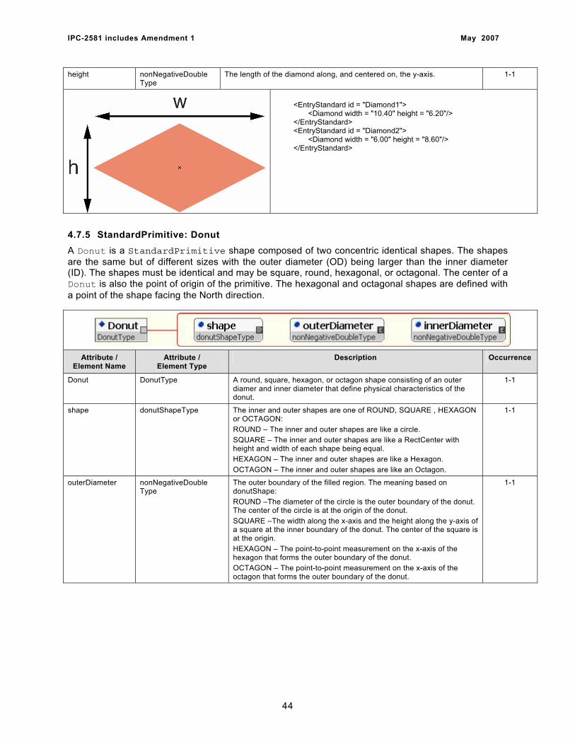
IPC-2581 includes Amendment 1 May 2007
height nonNegativeDouble Type
The length of the diamond along, and centered on, the y-axis. 1-1
<EntryStandard id = "Diamond1"> <Diamond width = "10.40" height = "6.20"/> </EntryStandard> <EntryStandard id = "Diamond2"> <Diamond width = "6.00" height = "8.60"/> </EntryStandard>
4.7.5 StandardPrimitive: Donut A Donut is a StandardPrimitive shape composed of two concentric identical shapes. The shapes are the same but of different sizes with the outer diameter (OD) being larger than the inner diameter (ID). The shapes must be identical and may be square, round, hexagonal, or octagonal. The center of a Donut is also the point of origin of the primitive. The hexagonal and octagonal shapes are defined with a point of the shape facing the North direction.
Attribute / Element Name
Attribute / Element Type
Description Occurrence
Donut DonutType A round, square, hexagon, or octagon shape consisting of an outer diamer and inner diameter that define physical characteristics of the donut.
1-1
shape donutShapeType The inner and outer shapes are one of ROUND, SQUARE , HEXAGON or OCTAGON: ROUND – The inner and outer shapes are like a circle. SQUARE – The inner and outer shapes are like a RectCenter with height and width of each shape being equal. HEXAGON – The inner and outer shapes are like a Hexagon. OCTAGON – The inner and outer shapes are like an Octagon.
1-1
outerDiameter nonNegativeDouble Type
The outer boundary of the filled region. The meaning based on donutShape: ROUND –The diameter of the circle is the outer boundary of the donut. The center of the circle is at the origin of the donut. SQUARE –The width along the x-axis and the height along the y-axis of a square at the inner boundary of the donut. The center of the square is at the origin. HEXAGON – The point-to-point measurement on the x-axis of the hexagon that forms the outer boundary of the donut. OCTAGON – The point-to-point measurement on the x-axis of the octagon that forms the outer boundary of the donut.
1-1
44
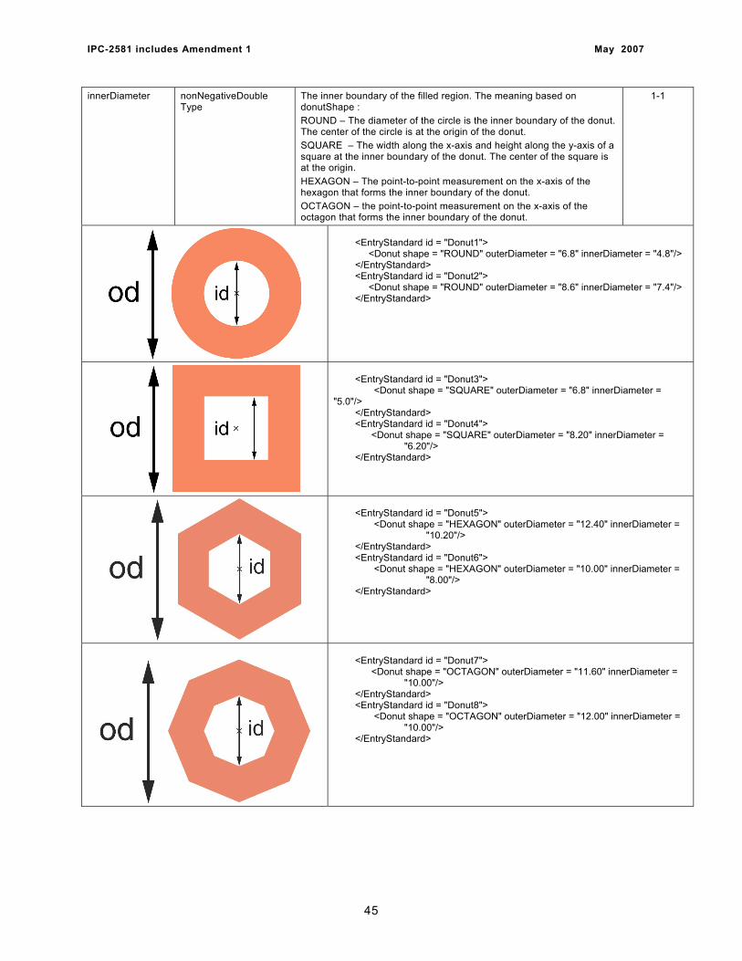
IPC-2581 includes Amendment 1 May 2007
innerDiameter nonNegativeDouble Type
The inner boundary of the filled region. The meaning based on donutShape : ROUND – The diameter of the circle is the inner boundary of the donut. The center of the circle is at the origin of the donut. SQUARE – The width along the x-axis and height along the y-axis of a square at the inner boundary of the donut. The center of the square is at the origin. HEXAGON – The point-to-point measurement on the x-axis of the hexagon that forms the inner boundary of the donut. OCTAGON – the point-to-point measurement on the x-axis of the octagon that forms the inner boundary of the donut.
1-1
<EntryStandard id = "Donut1"> <Donut shape = "ROUND" outerDiameter = "6.8" innerDiameter = "4.8"/> </EntryStandard> <EntryStandard id = "Donut2"> <Donut shape = "ROUND" outerDiameter = "8.6" innerDiameter = "7.4"/> </EntryStandard>
<EntryStandard id = "Donut3"> <Donut shape = "SQUARE" outerDiameter = "6.8" innerDiameter = "5.0"/> </EntryStandard> <EntryStandard id = "Donut4"> <Donut shape = "SQUARE" outerDiameter = "8.20" innerDiameter = "6.20"/> </EntryStandard>
<EntryStandard id = "Donut5"> <Donut shape = "HEXAGON" outerDiameter = "12.40" innerDiameter = "10.20"/> </EntryStandard> <EntryStandard id = "Donut6"> <Donut shape = "HEXAGON" outerDiameter = "10.00" innerDiameter = "8.00"/> </EntryStandard>
<EntryStandard id = "Donut7"> <Donut shape = "OCTAGON" outerDiameter = "11.60" innerDiameter = "10.00"/> </EntryStandard> <EntryStandard id = "Donut8"> <Donut shape = "OCTAGON" outerDiameter = "12.00" innerDiameter = "10.00"/> </EntryStandard>
45
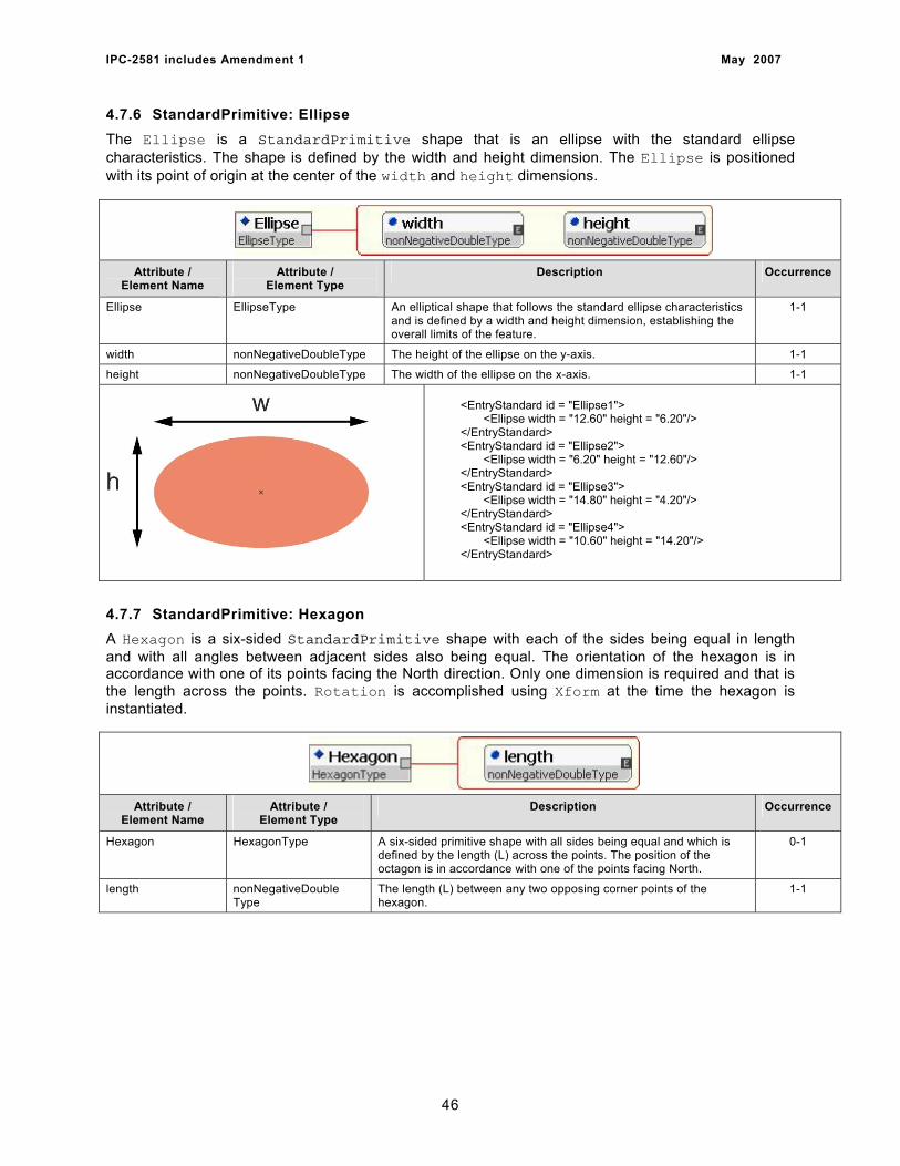
IPC-2581 includes Amendment 1 May 2007
4.7.6 StandardPrimitive: Ellipse The Ellipse is a StandardPrimitive shape that is an ellipse with the standard ellipse characteristics. The shape is defined by the width and height dimension. The Ellipse is positioned with its point of origin at the center of the width and height dimensions.
Attribute / Element Name
Attribute / Element Type
Description Occurrence
Ellipse EllipseType An elliptical shape that follows the standard ellipse characteristics and is defined by a width and height dimension, establishing the overall limits of the feature.
1-1
width nonNegativeDoubleType The height of the ellipse on the y-axis. 1-1
height nonNegativeDoubleType The width of the ellipse on the x-axis. 1-1
<EntryStandard id = "Ellipse1"> <Ellipse width = "12.60" height = "6.20"/> </EntryStandard> <EntryStandard id = "Ellipse2"> <Ellipse width = "6.20" height = "12.60"/> </EntryStandard> <EntryStandard id = "Ellipse3"> <Ellipse width = "14.80" height = "4.20"/> </EntryStandard> <EntryStandard id = "Ellipse4"> <Ellipse width = "10.60" height = "14.20"/> </EntryStandard>
4.7.7 StandardPrimitive: Hexagon A Hexagon is a six-sided StandardPrimitive shape with each of the sides being equal in length and with all angles between adjacent sides also being equal. The orientation of the hexagon is in accordance with one of its points facing the North direction. Only one dimension is required and that is the length across the points. Rotation is accomplished using Xform at the time the hexagon is instantiated.
Attribute / Element Name
Attribute / Element Type
Description Occurrence
Hexagon HexagonType A six-sided primitive shape with all sides being equal and which is defined by the length (L) across the points. The position of the octagon is in accordance with one of the points facing North.
0-1
length nonNegativeDouble Type
The length (L) between any two opposing corner points of the hexagon.
1-1
46
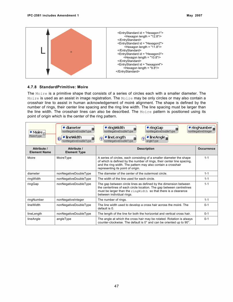
IPC-2581 includes Amendment 1 May 2007
<EntryStandard id = "Hexagon1"> <Hexagon length = "12.8"/> </EntryStandard> <EntryStandard id = "Hexagon2"> <Hexagon length = "11.8"/> </EntryStandard> <EntryStandard id = "Hexagon3"> <Hexagon length = "10.8"/> </EntryStandard> <EntryStandard id = "hexagon4"> <Hexagon length = "9.8"/> </EntryStandard>
4.7.8 StandardPrimitive: Moire The Moire is a primitive shape that consists of a series of circles each with a smaller diameter. The Moire is used as an assist in image registration. The Moire may be only circles or may also contain a crosshair line to assist in human acknowledgement of moiré alignment. The shape is defined by the number of rings, their center line spacing and the ring line width. The line spacing must be larger than the line width. The crosshair lines can also be described. The Moire pattern is positioned using its point of origin which is the center of the ring pattern.
Attribute / Element Name
Attribute / Element Type
Description Occurrence
Moire MoireType A series of circles, each consisting of a smaller diameter the shape of which is defined by the number of rings, their center line spacing, and the ring width. The pattern may also contain a crosshair representing its point of origin.
1-1
diameter nonNegativeDoubleType The diameter of the center of the outermost circle. 1-1
ringWidth nonNegativeDoubleType The width of the line used for each circle. 1-1
ringGap nonNegativeDoubleType The gap between circle lines as defined by the dimension between the centerlines of each circle location. The gap between centrelines must be larger than the ringWidth so that there is a clearance between individual rings.
1-1
ringNumber nonNegativeInteger The number of rings. 1-1
lineWidth nonNegativeDoubleType The line width used to develop a cross hair across the moiré. The default is 0.
0-1
lineLength nonNegativeDoubleType The length of the line for both the horizontal and vertical cross hair. 0-1
lineAngle angleType The angle at which the cross hair may be rotated. Rotation is always counter-clockwise. The default is 0° and can be oriented up to 90°.
0-1
47
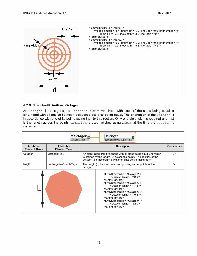
IPC-2581 includes Amendment 1 May 2007
<EntryStandard id = "Moire1"> <Moire diameter = "8.4" ringWidth = "0.3" ringGap = "0.6" ringNumber = "5" lineWidth = "0.3" lineLength = "8.2" lineAngle = "0"/> </EntryStandard> <EntryStandard id = "Moire2"> <Moire diameter = "6.0" ringWidth = "0.2" ringGap = "0.4" ringNumber = "4" lineWidth = "0.2" lineLength = "5.8" lineAngle = "45"/> </EntryStandard>
4.7.9 StandardPrimitive: Octagon An Octagon is an eight-sided StandardPrimitive shape with each of the sides being equal in length and with all angles between adjacent sides also being equal. The orientation of the Octagon is in accordance with one of its points facing the North direction. Only one dimension is required and that is the length across the points. Rotation is accomplished using Xform at the time the Octagon is instanced.
Attribute /
Element Name Attribute /
Element Type Description Occurrence
Octagon OctagonType An eight-sided primitive shape with all sides being equal and which is defined by the length (L) across the points. The position of the octagon is in accordance with one of its points facing north.
0-1
length nonNegativeDoubleType The length (L) between any two opposing corner points of the octagon.
0-1
<EntryStandard id = "Octagon1"> <Octagon length = "12.8"/> </EntryStandard> <EntryStandard id = "Octagon2"> <Octagon length = "11.8"/> </EntryStandard> <EntryStandard id = "Octagon3"> <Octagon length = "10.8"/> </EntryStandard> <EntryStandard id = "Octagon4"> <Octagon length = "9.8"/> </EntryStandard>
48
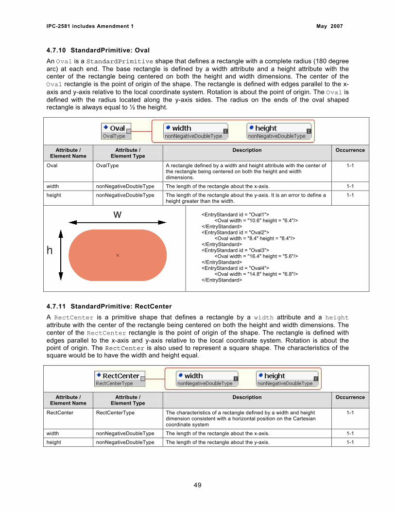
IPC-2581 includes Amendment 1 May 2007
4.7.10 StandardPrimitive: Oval An Oval is a StandardPrimitive shape that defines a rectangle with a complete radius (180 degree arc) at each end. The base rectangle is defined by a width attribute and a height attribute with the center of the rectangle being centered on both the height and width dimensions. The center of the Oval rectangle is the point of origin of the shape. The rectangle is defined with edges parallel to the x-axis and y-axis relative to the local coordinate system. Rotation is about the point of origin. The Oval is defined with the radius located along the y-axis sides. The radius on the ends of the oval shaped rectangle is always equal to ½ the height.
Attribute / Element Name
Attribute / Element Type
Description Occurrence
Oval OvalType A rectangle defined by a width and height attribute with the center of the rectangle being centered on both the height and width dimensions.
1-1
width nonNegativeDoubleType The length of the rectangle about the x-axis. 1-1
height nonNegativeDoubleType The length of the rectangle about the y-axis. It is an error to define a height greater than the width.
1-1
<EntryStandard id = "Oval1"> <Oval width = "10.6" height = "6.4"/> </EntryStandard> <EntryStandard id = "Oval2"> <Oval width = "8.4" height = "8.4"/> </EntryStandard> <EntryStandard id = "Oval3"> <Oval width = "16.4" height = "5.6"/> </EntryStandard> <EntryStandard id = "Oval4"> <Oval width = "14.8" height = "6.8"/> </EntryStandard>
4.7.11 StandardPrimitive: RectCenter A RectCenter is a primitive shape that defines a rectangle by a width attribute and a height attribute with the center of the rectangle being centered on both the height and width dimensions. The center of the RectCenter rectangle is the point of origin of the shape. The rectangle is defined with edges parallel to the x-axis and y-axis relative to the local coordinate system. Rotation is about the point of origin. The RectCenter is also used to represent a square shape. The characteristics of the square would be to have the width and height equal.
Attribute / Element Name
Attribute / Element Type
Description Occurrence
RectCenter RectCenterType The characteristics of a rectangle defined by a width and height dimension consistent with a horizontal position on the Cartesian coordinate system
1-1
width nonNegativeDoubleType The length of the rectangle about the x-axis. 1-1
height nonNegativeDoubleType The length of the rectangle about the y-axis. 1-1
49

IPC-2581 includes Amendment 1 May 2007
<EntryStandard id = "RectangleC1"> <RectCenter width = "16.8" height = "6.4"/> </EntryStandard> <EntryStandard id = "RectangleC2"> <RectCenter width = "6.4" height = "12.8"/> </EntryStandard> <EntryStandard id = "RectangleC3"> <RectCenter width = "10.4" height = "6.4"/> </EntryStandard>
<EntryStandard id = "RectangleSquare1"> <RectCenter width = "8.4" height = "8.4"/> </EntryStandard> <EntryStandard id = "RectangleSquare2"> <RectCenter width = "10.0" height = "10.0"/> </EntryStandard> <EntryStandard id = "RectangleSquare3"> <RectCenter width = "4.8" height = "4.8"/> </EntryStandard>
4.7.12 StandardPrimitive: RectCham A RectCham is a StandardPrimitive shape that defines a rectangle with chamfered corners. The base rectangle is defined by a width attribute and a height attribute with the center of the rectangle being centered on both the height and width dimensions. The center of the RectCham rectangle is the point of origin of the shape. The rectangle is defined with edges parallel to the x-axis and y-axis relative to the local coordinate system. Rotation is about the point of origin. The RectCham is also used to represent a square shape with chamfered corners. The characteristics of the square would be to have the width and height equal.
Attribute / Element Name
Attribute / Element Type
Description Occurrence
RectCham RectChamType A rectangle with one or more corners chamfered. The user has the option to define any of the corners as containing the chamfer as well as the chamfered dimensions. All chamfers (or opportunities for chamfers) must be identical in size.
1-1
width nonNegativeDouble Type
The length of the rectangle about the x-axis. 1-1
height nonNegativeDouble Type
The length of the rectangle about the y-axis. 1-1
chamfer nonNegativeDouble Type
The length measured from each corner that defines 4 points along the width and 4 points along the height. The corners are clipped between the points at each corner. The resulting chamfers are always cut at 45° relative to the local coordinate system. It is an error to define the value of chamfer to be greater than ½ the height or ½ the width.
1-1
upperRight boolean The upper right corner (1). 0-1
upperLeft boolean The upper left corner (2). 0-1
50
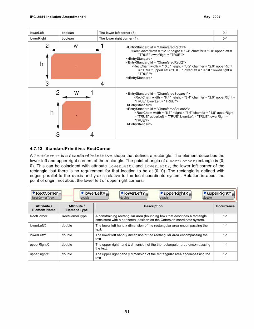
IPC-2581 includes Amendment 1 May 2007
lowerLeft boolean The lower left corner (3). 0-1
lowerRight boolean The lower right corner (4). 0-1
<EntryStandard id = "ChamferedRect1"> <RectCham width = "12.6" height = "8.4" chamfer = "2.0" upperLeft = "TRUE" lowerRight = "TRUE"/> </EntryStandard> <EntryStandard id = "ChamferedRect2"> <RectCham width = "10.6" height = "6.2" chamfer = "2.0" upperRight = "TRUE" upperLeft = "TRUE" lowerLeft = "TRUE" lowerRight = "TRUE"/> </EntryStandard>
<EntryStandard id = "ChamferedSquare1"> <RectCham width = "8.4" height = "8.4" chamfer = "2.0" upperRight = "TRUE" lowerLeft = "TRUE"/> </EntryStandard> <EntryStandard id = "ChamferedSquare2">
<RectCham width = "6.6" height = "6.6" chamfer = "1.8" upperRight = "TRUE" upperLeft = "TRUE" lowerLeft = "TRUE" lowerRight = "TRUE"/>
</EntryStandard>
4.7.13 StandardPrimitive: RectCorner A RectCorner is a StandardPrimitive shape that defines a rectangle. The element describes the lower left and upper right corners of the rectangle. The point of origin of a RectCorner rectangle is (0, 0). This can be coincident with attribute lowerLeftX and lowerLeftY, the lower left corner of the rectangle, but there is no requirement for that location to be at (0, 0). The rectangle is defined with edges parallel to the x-axis and y-axis relative to the local coordinate system. Rotation is about the point of origin, not about the lower left or upper right corners.
Attribute / Element Name
Attribute / Element Type
Description Occurrence
RectCorner RectCornerType A constraining rectangular area (bounding box) that describes a rectangle consistent with a horizontal position on the Cartesian coordinate system.
1-1
lowerLeftX double The lower left hand x dimension of the rectangular area encompassing the text.
1-1
lowerLeftY double The lower left hand y dimension of the rectangular area encompassing the text.
1-1
upperRightX double The upper right hand x dimension of the the rectangular area encompassing the text.
1-1
upperRightY double The upper right hand y dimension of the rectangular area encompassing the text.
1-1
51
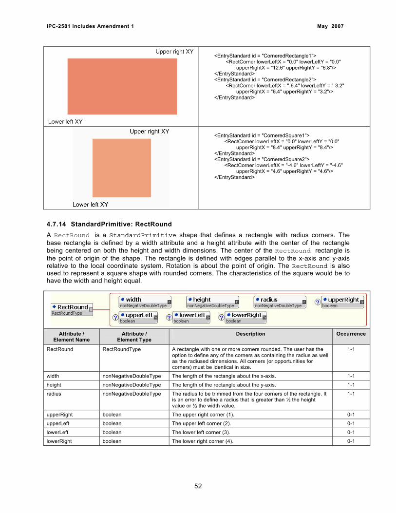
IPC-2581 includes Amendment 1 May 2007
<EntryStandard id = "CorneredRectangle1"> <RectCorner lowerLeftX = "0.0" lowerLeftY = "0.0" upperRightX = "12.6" upperRightY = "6.8"/> </EntryStandard> <EntryStandard id = "CorneredRectangle2"> <RectCorner lowerLeftX = "-6.4" lowerLeftY = "-3.2" upperRightX = "6.4" upperRightY = "3.2"/> </EntryStandard>
<EntryStandard id = "CorneredSquare1"> <RectCorner lowerLeftX = "0.0" lowerLeftY = "0.0" upperRightX = "8.4" upperRightY = "8.4"/> </EntryStandard> <EntryStandard id = "CorneredSquare2"> <RectCorner lowerLeftX = "-4.6" lowerLeftY = "-4.6" upperRightX = "4.6" upperRightY = "4.6"/> </EntryStandard>
4.7.14 StandardPrimitive: RectRound A RectRound is a StandardPrimitive shape that defines a rectangle with radius corners. The base rectangle is defined by a width attribute and a height attribute with the center of the rectangle being centered on both the height and width dimensions. The center of the RectRound rectangle is the point of origin of the shape. The rectangle is defined with edges parallel to the x-axis and y-axis relative to the local coordinate system. Rotation is about the point of origin. The RectRound is also used to represent a square shape with rounded corners. The characteristics of the square would be to have the width and height equal.
Attribute / Element Name
Attribute / Element Type
Description Occurrence
RectRound RectRoundType A rectangle with one or more corners rounded. The user has the option to define any of the corners as containing the radius as well as the radiused dimensions. All corners (or opportunities for corners) must be identical in size.
1-1
width nonNegativeDoubleType The length of the rectangle about the x-axis. 1-1
height nonNegativeDoubleType The length of the rectangle about the y-axis. 1-1
radius nonNegativeDoubleType The radius to be trimmed from the four corners of the rectangle. It is an error to define a radius that is greater than ½ the height value or ½ the width value.
1-1
upperRight boolean The upper right corner (1). 0-1
upperLeft boolean The upper left corner (2). 0-1
lowerLeft boolean The lower left corner (3). 0-1
lowerRight boolean The lower right corner (4). 0-1
52
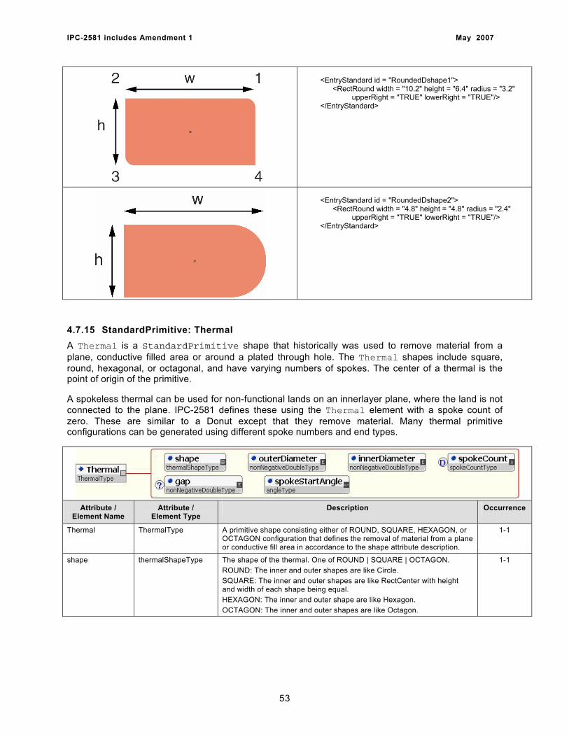
IPC-2581 includes Amendment 1 May 2007
<EntryStandard id = "RoundedDshape1"> <RectRound width = "10.2" height = "6.4" radius = "3.2" upperRight = "TRUE" lowerRight = "TRUE"/> </EntryStandard>
<EntryStandard id = "RoundedDshape2"> <RectRound width = "4.8" height = "4.8" radius = "2.4" upperRight = "TRUE" lowerRight = "TRUE"/> </EntryStandard>
4.7.15 StandardPrimitive: Thermal A Thermal is a StandardPrimitive shape that historically was used to remove material from a plane, conductive filled area or around a plated through hole. The Thermal shapes include square, round, hexagonal, or octagonal, and have varying numbers of spokes. The center of a thermal is the point of origin of the primitive.
A spokeless thermal can be used for non-functional lands on an innerlayer plane, where the land is not connected to the plane. IPC-2581 defines these using the Thermal element with a spoke count of zero. These are similar to a Donut except that they remove material. Many thermal primitive configurations can be generated using different spoke numbers and end types.
Attribute /
Element Name Attribute /
Element Type Description Occurrence
Thermal ThermalType A primitive shape consisting either of ROUND, SQUARE, HEXAGON, or OCTAGON configuration that defines the removal of material from a plane or conductive fill area in accordance to the shape attribute description.
1-1
shape thermalShapeType The shape of the thermal. One of ROUND | SQUARE | OCTAGON. ROUND: The inner and outer shapes are like Circle. SQUARE: The inner and outer shapes are like RectCenter with height and width of each shape being equal. HEXAGON: The inner and outer shape are like Hexagon. OCTAGON: The inner and outer shapes are like Octagon.
1-1
53
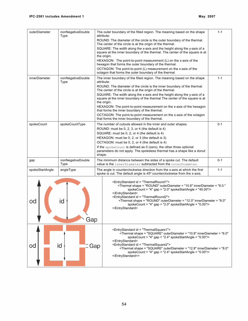
IPC-2581 includes Amendment 1 May 2007
outerDiameter nonNegativeDouble Type
The outer boundary of the filled region. The meaning based on the shape attribute: ROUND: The diameter of the circle is the outer boundary of the thermal. The center of the circle is at the origin of the thermal. SQUARE: The width along the x-axis and the height along the y-axis of a square at the inner boundary of the thermal. The center of the square is at the origin. HEXAGON: The point-to-point measurement (L) on the x-axis of the hexagon that forms the outer boundary of the thermal. OCTAGON: The point-to-point (L) measurement on the x-axis of the octagon that forms the outer boundary of the thermal.
1-1
innerDiameter nonNegativeDouble Type
The inner boundary of the filled region. The meaning based on the shape attribute: ROUND: The diameter of the circle is the inner boundary of the thermal. The center of the circle is at the origin of the thermal. SQUARE: The width along the x-axis and the height along the y-axis of a square at the inner boundary of the thermal The center of the square is at the origin. HEXAGON: The point-to-point measurement on the x-axis of the hexagon that forms the inner boundary of the thermal. OCTAGON: The point-to-point measurement on the x-axis of the octagon that forms the inner boundary of the thermal.
1-1
spokeCount spokeCountType The number of cutouts allowed in the inner and outer shapes. ROUND: must be 0, 2, 3, or 4 (the default is 4) SQUARE: must be 0, 2, or 4 (the default is 4) HEXAGON: must be 0, 2, or 3 (the default is 3) OCTAGON: must be 0, 2, or 4 (the default is 4) If the spokeCount is defined as 0 (zero), the other three optional parameters do not apply. The spokeless thermal has a shape like a donut shape.
0-1
gap nonNegativeDouble Type
The minimum distance between the sides of a spoke cut. The default value is the innerDiameter subtracted from the outerDiameter.
0-1
spokeStartAngle angleType The angle in counterclockwise direction from the x-axis at which the first spoke is cut. The default angle is 45º counterclockwise from the x-axis.
1-1
<EntryStandard id = "ThermalRound1"> <Thermal shape = "ROUND" outerDiameter = "10.6" innerDiameter = "6.0." spokeCount = "4" gap = "2.0" spokeStartAngle = "45.00"/> </EntryStandard> <EntryStandard id = "ThermalRound2"> <Thermal shape = "ROUND" outerDiameter = "12.0" innerDiameter = "8.0" spokeCount = "4" gap = "2.0" spokeStartAngle = "0.00"/> </EntryStandard>
<EntryStandard id = "ThermalSquare1"> <Thermal shape = "SQUARE" outerDiameter = "10.8" innerDiameter = "6.0" spokeCount = "4" gap = "2.4" spokeStartAngle = "0.00"/> </EntryStandard> <EntryStandard id = "ThermalSquare2"> <Thermal shape = "SQUARE" outerDiameter = "12.8" innerDiameter = "8.0" spokeCount = "4" gap = "2.4" spokeStartAngle = "0.00"/> </EntryStandard>>
54
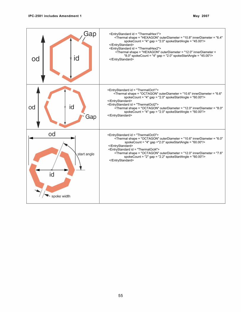
IPC-2581 includes Amendment 1 May 2007
<EntryStandard id = "ThermalHex1"> <Thermal shape = "HEXAGON" outerDiameter = "10.8" innerDiameter = "6.4" spokeCount = "4" gap = "2.0" spokeStartAngle = "45.00"/> </EntryStandard> <EntryStandard id = "ThermalHex2"> <Thermal shape = "HEXAGON" outerDiameter = "12.0" innerDiameter = "8.0" spokeCount = "4" gap = "2.0" spokeStartAngle = "45.00"/> </EntryStandard>
<EntryStandard id = "ThermalOct1"> <Thermal shape = "OCTAGON" outerDiameter = "10.6" innerDiameter = "6.6" spokeCount = "4" gap = "2.0" spokeStartAngle = "60.00"/> </EntryStandard> <EntryStandard id = "ThermalOct2"> <Thermal shape = "OCTAGON" outerDiameter = "12.0" innerDiameter = "8.0" spokeCount = "4" gap = "2.0" spokeStartAngle = "60.00"/> </EntryStandard>
<EntryStandard id = "ThermalOct3"> <Thermal shape = "OCTAGON" outerDiameter = "10.6" innerDiameter = "6.0" spokeCount = "4" gap ="2.0" spokeStartAngle = "60.00"/> </EntryStandard> <EntryStandard id = "ThermalOct4"> <Thermal shape = "OCTAGON" outerDiameter = "12.0" innerDiameter = "7.6" spokeCount = "2" gap = "2.2" spokeStartAngle = "60.00"/> </EntryStandard>
55
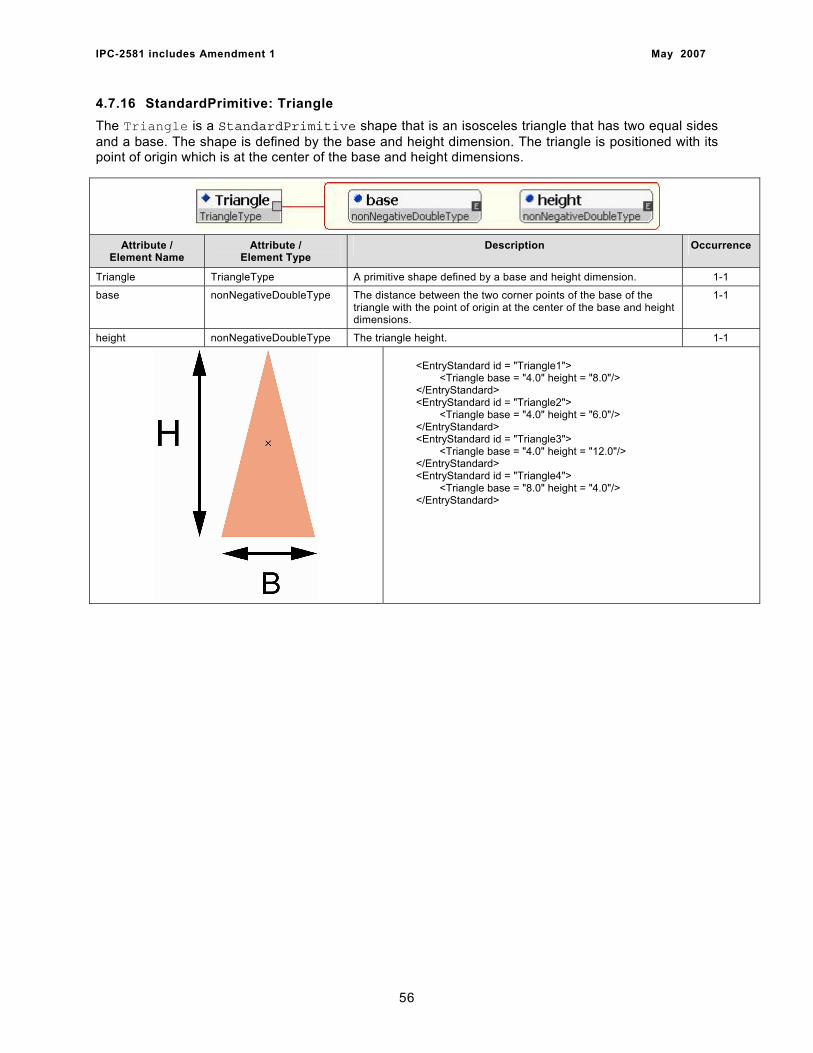
IPC-2581 includes Amendment 1 May 2007
4.7.16 StandardPrimitive: Triangle The Triangle is a StandardPrimitive shape that is an isosceles triangle that has two equal sides and a base. The shape is defined by the base and height dimension. The triangle is positioned with its point of origin which is at the center of the base and height dimensions.
Attribute / Element Name
Attribute / Element Type
Description Occurrence
Triangle TriangleType A primitive shape defined by a base and height dimension. 1-1
base nonNegativeDoubleType The distance between the two corner points of the base of the triangle with the point of origin at the center of the base and height dimensions.
1-1
height nonNegativeDoubleType The triangle height. 1-1 <EntryStandard id = "Triangle1"> <Triangle base = "4.0" height = "8.0"/> </EntryStandard> <EntryStandard id = "Triangle2"> <Triangle base = "4.0" height = "6.0"/> </EntryStandard> <EntryStandard id = "Triangle3"> <Triangle base = "4.0" height = "12.0"/> </EntryStandard> <EntryStandard id = "Triangle4"> <Triangle base = "8.0" height = "4.0"/> </EntryStandard>
56
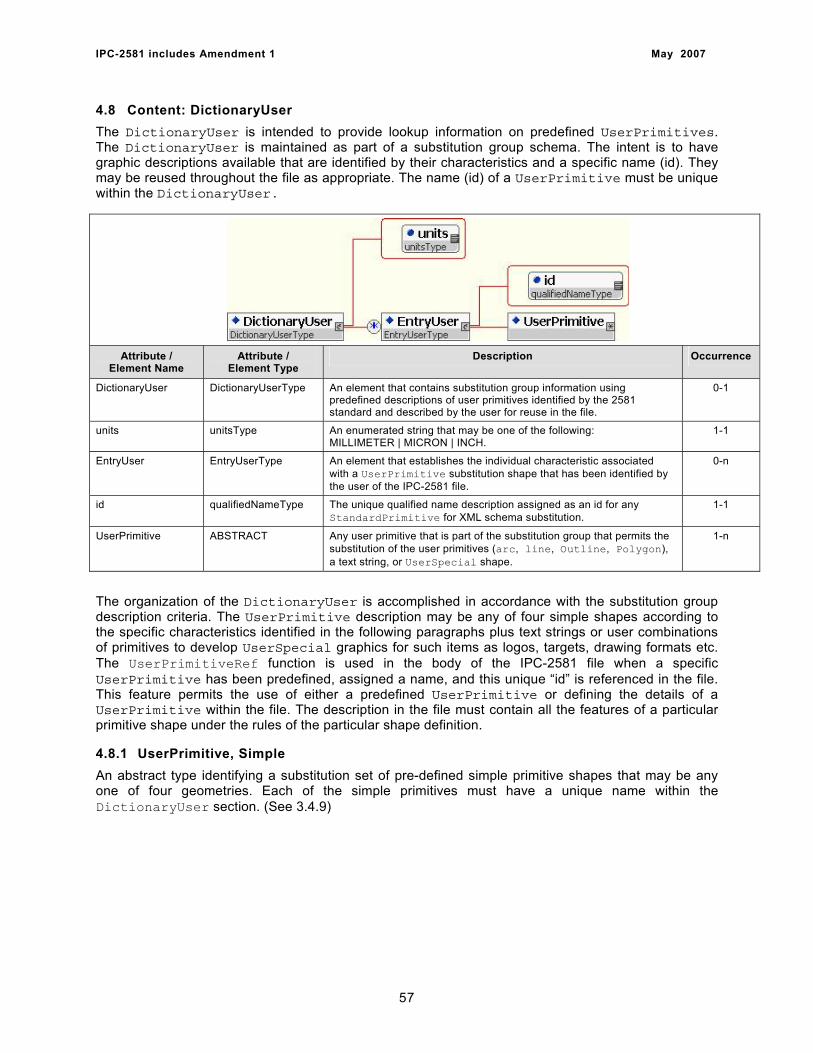
IPC-2581 includes Amendment 1 May 2007
4.8 Content: DictionaryUser The DictionaryUser is intended to provide lookup information on predefined UserPrimitives. The DictionaryUser is maintained as part of a substitution group schema. The intent is to have graphic descriptions available that are identified by their characteristics and a specific name (id). They may be reused throughout the file as appropriate. The name (id) of a UserPrimitive must be unique within the DictionaryUser.
Attribute / Element Name
Attribute / Element Type
Description Occurrence
DictionaryUser DictionaryUserType An element that contains substitution group information using predefined descriptions of user primitives identified by the 2581 standard and described by the user for reuse in the file.
0-1
units unitsType An enumerated string that may be one of the following: MILLIMETER | MICRON | INCH.
1-1
EntryUser EntryUserType An element that establishes the individual characteristic associated with a UserPrimitive substitution shape that has been identified by the user of the IPC-2581 file.
0-n
id qualifiedNameType The unique qualified name description assigned as an id for any StandardPrimitive for XML schema substitution.
1-1
UserPrimitive ABSTRACT Any user primitive that is part of the substitution group that permits the substitution of the user primitives (arc, line, Outline, Polygon), a text string, or UserSpecial shape.
1-n
The organization of the DictionaryUser is accomplished in accordance with the substitution group description criteria. The UserPrimitive description may be any of four simple shapes according to the specific characteristics identified in the following paragraphs plus text strings or user combinations of primitives to develop UserSpecial graphics for such items as logos, targets, drawing formats etc. The UserPrimitiveRef function is used in the body of the IPC-2581 file when a specific UserPrimitive has been predefined, assigned a name, and this unique “id” is referenced in the file. This feature permits the use of either a predefined UserPrimitive or defining the details of a UserPrimitive within the file. The description in the file must contain all the features of a particular primitive shape under the rules of the particular shape definition.
4.8.1 UserPrimitive, Simple An abstract type identifying a substitution set of pre-defined simple primitive shapes that may be any one of four geometries. Each of the simple primitives must have a unique name within the DictionaryUser section. (See 3.4.9)
57
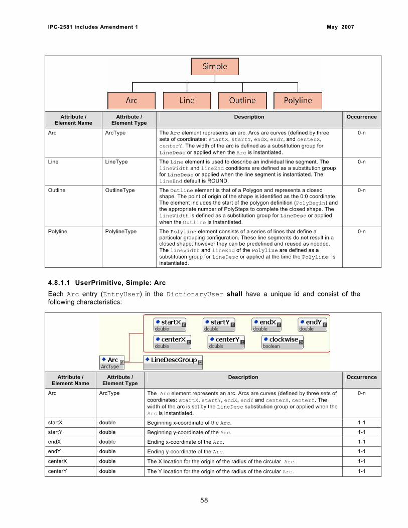
IPC-2581 includes Amendment 1 May 2007
Attribute / Element Name
Attribute / Element Type
Description Occurrence
Arc ArcType The Arc element represents an arc. Arcs are curves (defined by three sets of coordinates: startX, startY, endX, endY, and centerX, centerY. The width of the arc is defined as a substitution group for LineDesc or applied when the Arc is instantiated.
0-n
Line LineType The Line element is used to describe an individual line segment. The lineWidth and lineEnd conditions are defined as a substitution group for LineDesc or applied when the line segment is instantiated. The lineEnd default is ROUND.
0-n
Outline OutlineType The Outline element is that of a Polygon and represents a closed shape. The point of origin of the shape is identified as the 0:0 coordinate. The element includes the start of the polygon definition (PolyBegin) and the appropriate number of PolySteps to complete the closed shape. The lineWidth is defined as a substitution group for LineDesc or applied when the Outline is instantiated.
0-n
Polyline PolylineType The Polyline element consists of a series of lines that define a particular grouping configuration. These line segments do not result in a closed shape, however they can be predefined and reused as needed. The lineWidth and lineEnd of the Polyline are defined as a substitution group for LineDesc or applied at the time the Polyline is instantiated.
0-n
4.8.1.1 UserPrimitive, Simple: Arc Each Arc entry (EntryUser) in the DictionaryUser shall have a unique id and consist of the following characteristics:
Attribute / Element Name
Attribute / Element Type
Description Occurrence
Arc ArcType The Arc element represents an arc. Arcs are curves (defined by three sets of coordinates: startX, startY, endX, endY and centerX, centerY. The width of the arc is set by the LineDesc substitution group or applied when the Arc is instantiated.
0-n
startX double Beginning x-coordinate of the Arc. 1-1
startY double Beginning y-coordinate of the Arc. 1-1
endX double Ending x-coordinate of the Arc. 1-1
endY double Ending y-coordinate of the Arc. 1-1
centerX double The X location for the origin of the radius of the circular Arc. 1-1
centerY double The Y location for the origin of the radius of the circular Arc. 1-1
58

IPC-2581 includes Amendment 1 May 2007
clockwise boolean An enumerated string as either TRUE or FALSE (part of the 3WC standard). TRUE equals that the Arc is in a clockwise direction; FALSE is the default indicating a counterclockwise direction.
0-1
LineDescGroup ABSTRACT A substitution group that specifies the LineWidth and LineEnd characteristics of the Arc by reference to a predefined LineDesc or specified when the Arc is instantiated.
1-1
<EntryUser id = "Arc1">
<Arc startX = "8.0" startY = "0.0" endX = "-8.0" endY = "0.0" centerX = "0.0" centerY = "0.0" clockwise = "FALSE"> <LineDescRef id = "MediumLine"/> </Arc> </EntryUser> <EntryUser id = "Arc2"> <Arc startX = "0.0" startY = "0.0" endX = "12.0" endY = "0.0" centerX = "6.0" centerY = "0.0" clockwise = "TRUE"> <LineDescRef id = "HeavyLine"/> </Arc> </EntryUser> <EntryUser id = "Arc3"> <Arc startX = "-8.0" startY = "0.0" endX = "0.0" endY = "8.0" centerX = "0.0" centerY = "0.0" clockwise = "TRUE"> <LineDesc lineEnd = "ROUND" lineWidth = "1.0"/> </Arc>
</EntryUser>
4.8.1.2 UserPrimitive, Simple: Line Each Line entry (EntryUser) in the DictionaryUser shall have a unique id and consist of the following characteristics:
Attribute / Element Name
Attribute / Element Type
Description Occurrence
Line LineType The Line element is used to describe an individual line segment. The lineWidth and lineEnd conditions are defined by the LineDescGroup or when the line is instantiated. The lineEnd default is ROUND.
0-n
startX double Beginning x-coordinate of the Line. 1-1
startY double Beginning y-coordinate of the Line. 1-1
endX double Ending x-coordinate of the Line. 1-1
endY double Ending y-coordinate of the Line. 1-1
LineDescGroup ABSTRACT A substitution group that specifies the LineWidth and LineEnd characteristics of the Line by reference to a predefined LineDesc or specified when the Line is instantiated.
1-1
59
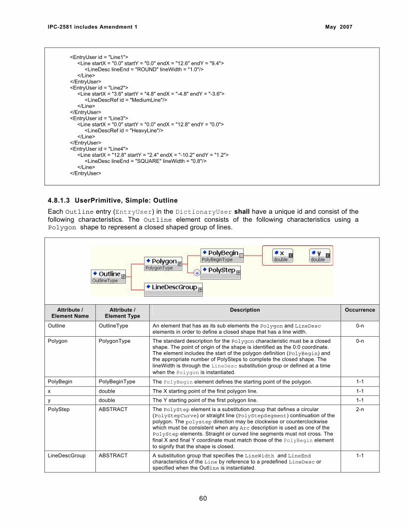
IPC-2581 includes Amendment 1 May 2007
<EntryUser id = "Line1"> <Line startX = "0.0" startY = "0.0" endX = "12.6" endY = "9.4"> <LineDesc lineEnd = "ROUND" lineWidth = "1.0"/> </Line> </EntryUser> <EntryUser id = "Line2"> <Line startX = "3.6" startY = "4.8" endX = "-4.8" endY = "-3.6"> <LineDescRef id = "MediumLine"/> </Line> </EntryUser> <EntryUser id = "Line3"> <Line startX = "0.0" startY = "0.0" endX = "12.8" endY = "0.0"> <LineDescRef id = "HeavyLine"/> </Line> </EntryUser> <EntryUser id = "Line4"> <Line startX = "12.8" startY = "2.4" endX = "-10.2" endY = "1.2"> <LineDesc lineEnd = "SQUARE" lineWidth = "0.8"/> </Line> </EntryUser>
4.8.1.3 UserPrimitive, Simple: Outline Each Outline entry (EntryUser) in the DictionaryUser shall have a unique id and consist of the following characteristics. The Outline element consists of the following characteristics using a Polygon shape to represent a closed shaped group of lines.
Attribute / Element Name
Attribute / Element Type
Description Occurrence
Outline OutlineType An element that has as its sub elements the Polygon and LineDesc elements in order to define a closed shape that has a line width.
0-n
Polygon PolygonType The standard description for the Polygon characteristic must be a closed shape. The point of origin of the shape is identified as the 0:0 coordinate. The element includes the start of the polygon definition (PolyBegin) and the appropriate number of PolySteps to complete the closed shape. The lineWidth is through the LineDesc substitution group or defined at a time when the Polygon is instantiated.
0-n
PolyBegin PolyBeginType The PolyBegin element defines the starting point of the polygon. 1-1
x double The X starting point of the first polygon line. 1-1
y double The Y starting point of the first polygon line. 1-1
PolyStep ABSTRACT The PolyStep element is a substitution group that defines a circular (PolyStepCurve) or straight line (PolyStepSegment) continuation of the polygon. The polystep direction may be clockwise or counterclockwise which must be consistent when any Arc description is used as one of the PolyStep elements. Straight or curved line segments must not cross. The final X and final Y coordinate must match those of the PolyBegin element to signify that the shape is closed.
2-n
LineDescGroup ABSTRACT A substitution group that specifies the LineWidth and LineEnd characteristics of the Line by reference to a predefined LineDesc or specified when the Outline is instantiated.
1-1
60
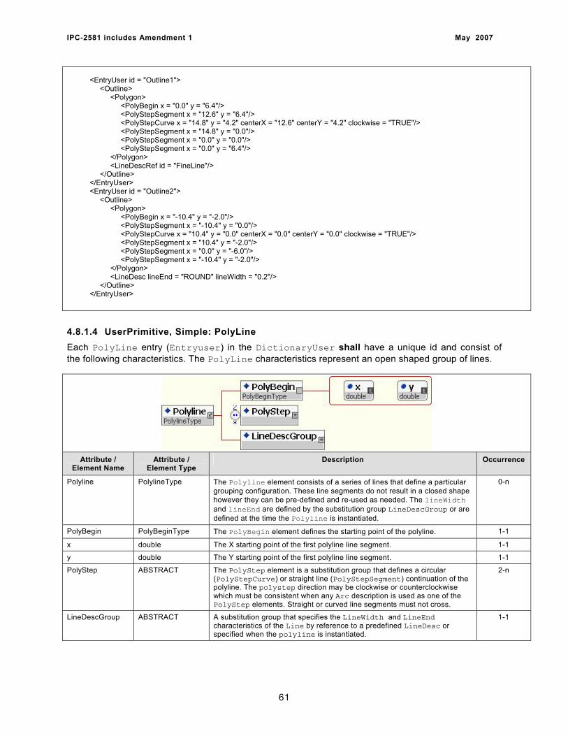
IPC-2581 includes Amendment 1 May 2007
<EntryUser id = "Outline1"> <Outline> <Polygon> <PolyBegin x = "0.0" y = "6.4"/> <PolyStepSegment x = "12.6" y = "6.4"/> <PolyStepCurve x = "14.8" y = "4.2" centerX = "12.6" centerY = "4.2" clockwise = "TRUE"/> <PolyStepSegment x = "14.8" y = "0.0"/> <PolyStepSegment x = "0.0" y = "0.0"/> <PolyStepSegment x = "0.0" y = "6.4"/> </Polygon> <LineDescRef id = "FineLine"/> </Outline> </EntryUser> <EntryUser id = "Outline2"> <Outline> <Polygon> <PolyBegin x = "-10.4" y = "-2.0"/> <PolyStepSegment x = "-10.4" y = "0.0"/> <PolyStepCurve x = "10.4" y = "0.0" centerX = "0.0" centerY = "0.0" clockwise = "TRUE"/> <PolyStepSegment x = "10.4" y = "-2.0"/> <PolyStepSegment x = "0.0" y = "-6.0"/> <PolyStepSegment x = "-10.4" y = "-2.0"/> </Polygon> <LineDesc lineEnd = "ROUND" lineWidth = "0.2"/> </Outline> </EntryUser>
4.8.1.4 UserPrimitive, Simple: PolyLine Each PolyLine entry (Entryuser) in the DictionaryUser shall have a unique id and consist of the following characteristics. The PolyLine characteristics represent an open shaped group of lines.
Attribute /
Element Name Attribute /
Element Type Description Occurrence
Polyline PolylineType The Polyline element consists of a series of lines that define a particular grouping configuration. These line segments do not result in a closed shape however they can be pre-defined and re-used as needed. The lineWidth and lineEnd are defined by the substitution group LineDescGroup or are defined at the time the Polyline is instantiated.
0-n
PolyBegin PolyBeginType The PolyBegin element defines the starting point of the polyline. 1-1
x double The X starting point of the first polyline line segment. 1-1
y double The Y starting point of the first polyline line segment. 1-1
PolyStep ABSTRACT The PolyStep element is a substitution group that defines a circular (PolyStepCurve) or straight line (PolyStepSegment) continuation of the polyline. The polystep direction may be clockwise or counterclockwise which must be consistent when any Arc description is used as one of the PolyStep elements. Straight or curved line segments must not cross.
2-n
LineDescGroup ABSTRACT A substitution group that specifies the LineWidth and LineEnd characteristics of the Line by reference to a predefined LineDesc or specified when the polyline is instantiated.
1-1
61
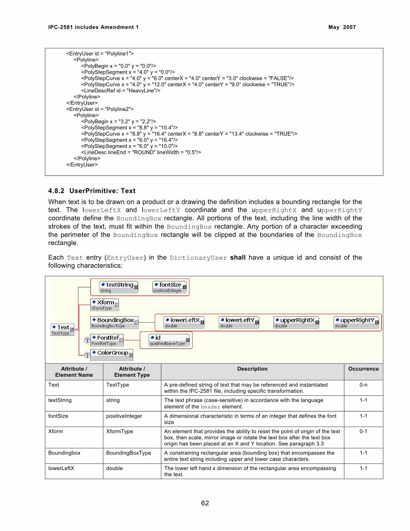
IPC-2581 includes Amendment 1 May 2007
<EntryUser id = "Polyline1"> <Polyline> <PolyBegin x = "0.0" y = "0.0"/> <PolyStepSegment x = "4.0" y = "0.0"/> <PolyStepCurve x = "4.0" y = "6.0" centerX = "4.0" centerY = "3.0" clockwise = "FALSE"/> <PolyStepCurve x = "4.0" y = "12.0" centerX = "4.0" centerY = "9.0" clockwise = "TRUE"/> <LineDescRef id = "HeavyLine"/> </Polyline> </EntryUser> <EntryUser id = "Polyline2"> <Polyline> <PolyBegin x = "3.2" y = "2.2"/> <PolyStepSegment x = "8.8" y = "10.4"/> <PolyStepCurve x = "8.8" y = "16.4" centerX = "8.8" centerY = "13.4" clockwise = "TRUE"/> <PolyStepSegment x = "6.0" y = "16.4"/> <PolyStepSegment x = "6.0" y = "10.0"/> <LineDesc lineEnd = "ROUND" lineWidth = "0.5"/> </Polyline> </EntryUser> 4.8.2 UserPrimitive: Text When text is to be drawn on a product or a drawing the definition includes a bounding rectangle for the text. The lowerLeftX and lowerLeftY coordinate and the upperRightX and upperRightY coordinate define the BoundingBox rectangle. All portions of the text, including the line width of the strokes of the text, must fit within the BoundingBox rectangle. Any portion of a character exceeding the perimeter of the BoundingBox rectangle will be clipped at the boundaries of the BoundingBox rectangle.
Each Text entry (EntryUser) in the DictionaryUser shall have a unique id and consist of the following characteristics:
Attribute / Element Name
Attribute / Element Type
Description Occurrence
Text TextType A pre-defined string of text that may be referenced and instantiated within the IPC-2581 file, including specific transformation.
0-n
textString string The text phrase (case-sensitive) in accordance with the language element of the Header element.
1-1
fontSize positiveInteger A dimensional characteristic in terms of an integer that defines the font size
1-1
Xform XformType An element that provides the ability to reset the point of origin of the text box, then scale, mirror image or rotate the text box after the text box origin has been placed at an X and Y location. See paragraph 3.3
0-1
Boundingbox BoundingBoxType A constraining rectangular area (bounding box) that encompasses the entire text string including upper and lower case characters.
1-1
lowerLeftX double The lower left hand x dimension of the rectangular area encompassing the text.
1-1
62
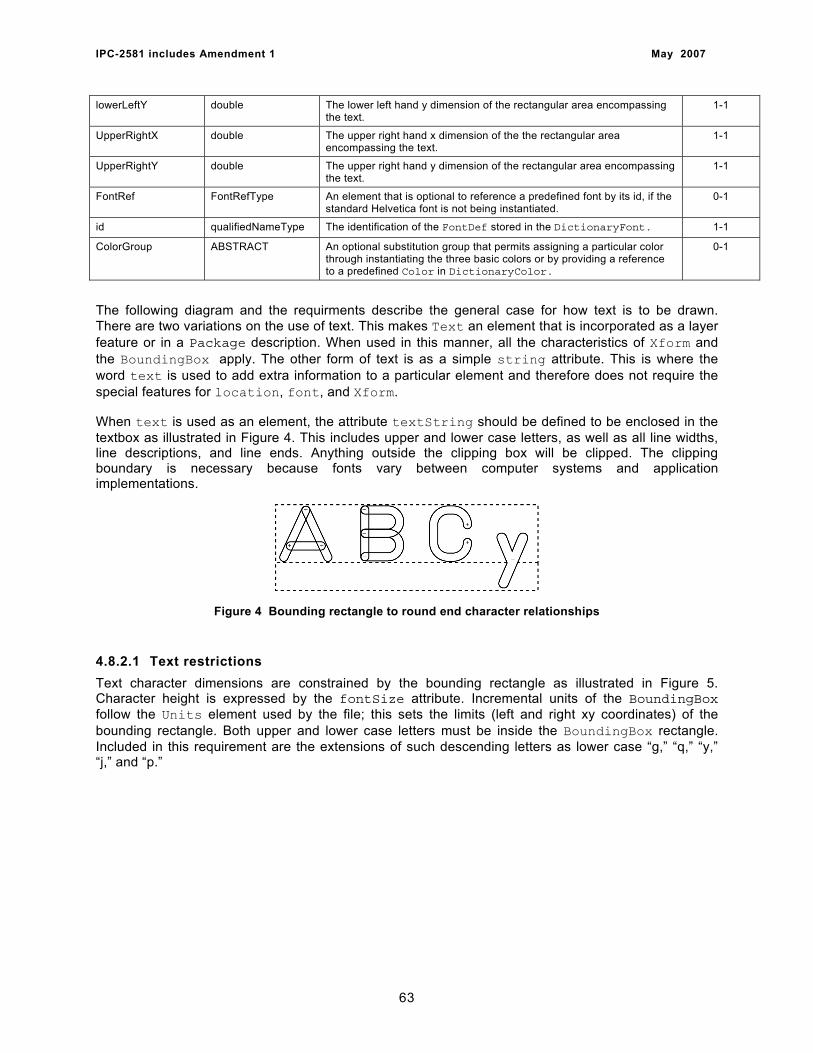
IPC-2581 includes Amendment 1 May 2007
lowerLeftY double The lower left hand y dimension of the rectangular area encompassing the text.
1-1
UpperRightX double The upper right hand x dimension of the the rectangular area encompassing the text.
1-1
UpperRightY double The upper right hand y dimension of the rectangular area encompassing the text.
1-1
FontRef FontRefType An element that is optional to reference a predefined font by its id, if the standard Helvetica font is not being instantiated.
0-1
id qualifiedNameType The identification of the FontDef stored in the DictionaryFont. 1-1
ColorGroup ABSTRACT An optional substitution group that permits assigning a particular color through instantiating the three basic colors or by providing a reference to a predefined Color in DictionaryColor.
0-1
The following diagram and the requirments describe the general case for how text is to be drawn. There are two variations on the use of text. This makes Text an element that is incorporated as a layer feature or in a Package description. When used in this manner, all the characteristics of Xform and the BoundingBox apply. The other form of text is as a simple string attribute. This is where the word text is used to add extra information to a particular element and therefore does not require the special features for location, font, and Xform.
When text is used as an element, the attribute textString should be defined to be enclosed in the textbox as illustrated in Figure 4. This includes upper and lower case letters, as well as all line widths, line descriptions, and line ends. Anything outside the clipping box will be clipped. The clipping boundary is necessary because fonts vary between computer systems and application implementations.
Figure 4 Bounding rectangle to round end character relationships
4.8.2.1 Text restrictions Text character dimensions are constrained by the bounding rectangle as illustrated in Figure 5. Character height is expressed by the fontSize attribute. Incremental units of the BoundingBox follow the Units element used by the file; this sets the limits (left and right xy coordinates) of the bounding rectangle. Both upper and lower case letters must be inside the BoundingBox rectangle. Included in this requirement are the extensions of such descending letters as lower case “g,” “q,” “y,” “j,” and “p.”
63

IPC-2581 includes Amendment 1 May 2007
Figure 5 Text transformation examples
4.8.2.2 Text rotation The bounding rectangle of Text is defined relative to the local coordinate system. The xLocation and yLocation of Xform is applied to the bounding rectangle and the text contained within the rectangle to locate the Text. The bounding rectangle must be mirrored if required before it is rotated. The text is drawn relative to the bounding rectangle.
The example shown in Figure 6 indicates a BoundingBox rectangle that has been rotated 30° about the lower left xy coordinate.
Figure 6 Rotation Angle
4.8.3 UserPrimitive: UserSpecial Each UserSpecial entry (EntryUser) in the DictionaryUser shall have a unique id and consist of the following characteristics. The UserSpecial may be any combination of StandardShapes or UserShapes, and is used to develop logos, targets, drawing formats or other combination of shapes.
64
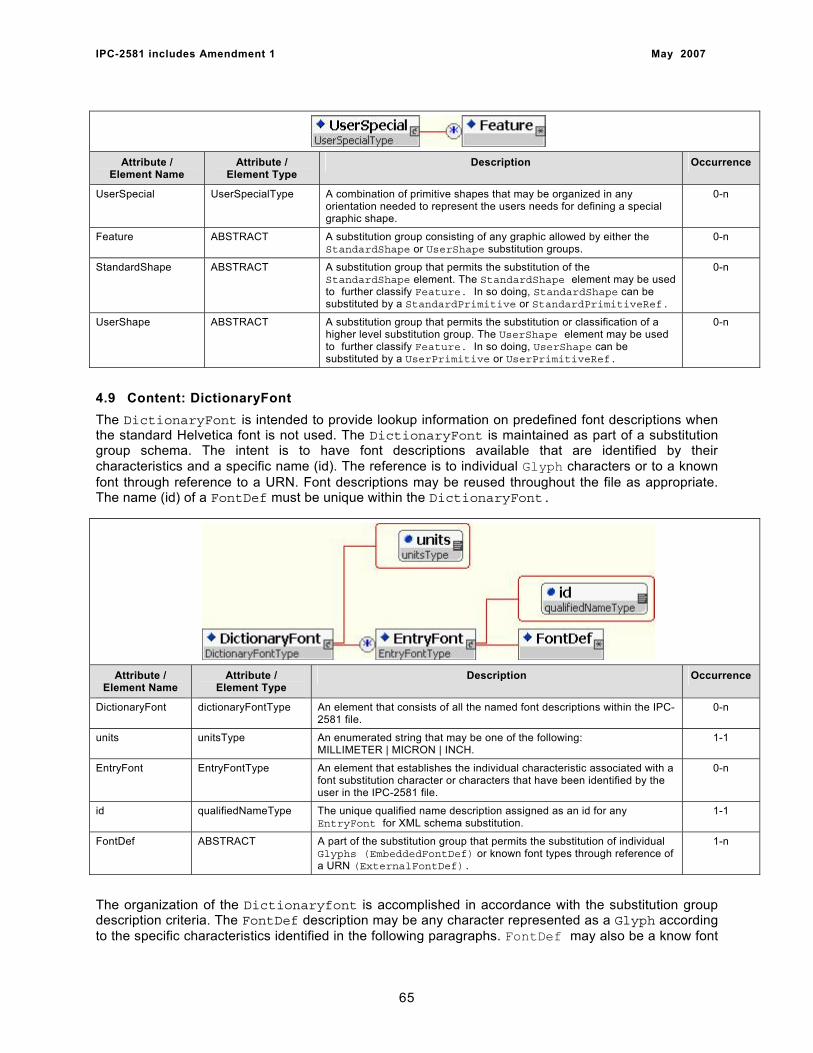
IPC-2581 includes Amendment 1 May 2007
Attribute / Element Name
Attribute / Element Type
Description Occurrence
UserSpecial UserSpecialType A combination of primitive shapes that may be organized in any orientation needed to represent the users needs for defining a special graphic shape.
0-n
Feature ABSTRACT A substitution group consisting of any graphic allowed by either the StandardShape or UserShape substitution groups.
0-n
StandardShape ABSTRACT A substitution group that permits the substitution of the StandardShape element. The StandardShape element may be used to further classify Feature. In so doing, StandardShape can be substituted by a StandardPrimitive or StandardPrimitiveRef.
0-n
UserShape ABSTRACT A substitution group that permits the substitution or classification of a higher level substitution group. The UserShape element may be used to further classify Feature. In so doing, UserShape can be substituted by a UserPrimitive or UserPrimitiveRef.
0-n
4.9 Content: DictionaryFont The DictionaryFont is intended to provide lookup information on predefined font descriptions when the standard Helvetica font is not used. The DictionaryFont is maintained as part of a substitution group schema. The intent is to have font descriptions available that are identified by their characteristics and a specific name (id). The reference is to individual Glyph characters or to a known font through reference to a URN. Font descriptions may be reused throughout the file as appropriate. The name (id) of a FontDef must be unique within the DictionaryFont.
Attribute / Element Name
Attribute / Element Type
Description Occurrence
DictionaryFont dictionaryFontType An element that consists of all the named font descriptions within the IPC-2581 file.
0-n
units unitsType An enumerated string that may be one of the following: MILLIMETER | MICRON | INCH.
1-1
EntryFont EntryFontType An element that establishes the individual characteristic associated with a font substitution character or characters that have been identified by the user in the IPC-2581 file.
0-n
id qualifiedNameType The unique qualified name description assigned as an id for any EntryFont for XML schema substitution.
1-1
FontDef ABSTRACT A part of the substitution group that permits the substitution of individual Glyphs (EmbeddedFontDef) or known font types through reference of a URN (ExternalFontDef).
1-n
The organization of the Dictionaryfont is accomplished in accordance with the substitution group description criteria. The FontDef description may be any character represented as a Glyph according to the specific characteristics identified in the following paragraphs. FontDef may also be a know font
65

IPC-2581 includes Amendment 1 May 2007
through reference of a URN. The FontRef function is used in the body of the IPC-2581 file when a specific font has been predefined, assigned a name, and the unique “id” is referenced in the file. This feature permits the substitution of the standard Helvetica font; Font descriptions are only contained in the DictionaryFont and are not instantiated in the body of the IPC-2581 file.
4.9.1 FontDefEmbedded The FontDefEmbedded element is used to capture individual characters and store them in the DictionaryFont.
Attribute / Element Name
Attribute / Element Type
Description Occurrence
FontDefEmbedded FontDefEmbeddedType A substitution for FontDef that identifies an individual Glyph character by a specific name and the Glyph characteristics.
0-n
name string A unique name related to the charCode of the Glyph character. 0-n
LineDescGroup ABSTRACT A substitution group that specifies the LineWidth and LineEnd characteristics of the Font by reference to a predefined LineDesc or specified when the font is instantiated.
1-1
Glyph GlyphType The element that contains the description of all the character definitions defined in the user developed font
1-n
4.9.2 FontDefExternal The FontDefExternal element is used to capture known font characters and store the reference in the DictionaryFont.
Attribute / Element Name
Attribute / Element Type
Description Occurrence
FontDefExternal FontDefExternalType A substitution for FontDef that identifies a known group of characters through their font style.
0-n
name string A unique name related to the character set of a known font. 0-n
urn urn A specific urn that makes reference to a known font that has the appropriate permission to use the font substitution in a 2581 file.
1-1
4.9.3 FontDef: Glyph The Glyph character set is a group of user defined characters that will be reference by the text command in the file. Glyph permits the user to define a special set of characters that need description as a part of the IPC-2581 file. Each character is in a BoundingBox that contains all the line strokes needed to completely define each character in the set. The point of origin is the lower left hand corner of the BoundingBox. The lowerLeftX and lowerLeftY point of origin will be used to position, rotate or mirror image all Glyph characters.
66
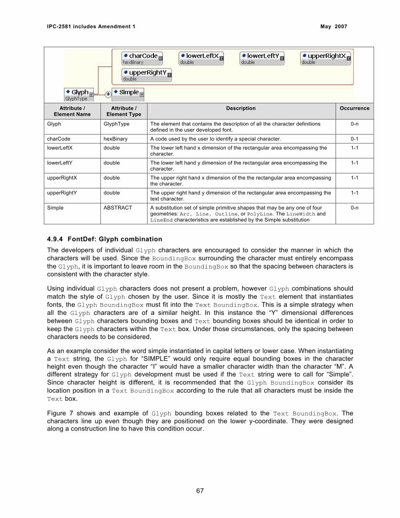
IPC-2581 includes Amendment 1 May 2007
Attribute /
Element Name Attribute /
Element Type Description Occurrence
Glyph GlyphType The element that contains the description of all the character definitions defined in the user developed font.
0-n
charCode hexBinary A code used by the user to identify a special character. 0-1
lowerLeftX double The lower left hand x dimension of the rectangular area encompassing the character.
1-1
lowerLeftY double The lower left hand y dimension of the rectangular area encompassing the character.
1-1
upperRightX double The upper right hand x dimension of the the rectangular area encompassing the character.
1-1
upperRightY double The upper right hand y dimension of the rectangular area encompassing the text character.
1-1
Simple ABSTRACT A substitution set of simple primitive shapes that may be any one of four geometries: Arc, Line, Outline, or PolyLine. The LineWidth and LineEnd characteristics are established by the Simple substitution
0-n
4.9.4 FontDef: Glyph combination The developers of individual Glyph characters are encouraged to consider the manner in which the characters will be used. Since the BoundingBox surrounding the character must entirely encompass the Glyph, it is important to leave room in the BoundingBox so that the spacing between characters is consistent with the character style.
Using individual Glyph characters does not present a problem, however Glyph combinations should match the style of Glyph chosen by the user. Since it is mostly the Text element that instantiates fonts, the Glyph BoundingBox must fit into the Text BoundingBox. This is a simple strategy when all the Glyph characters are of a similar height. In this instance the “Y” dimensional differences between Glyph characters bounding boxes and Text bounding boxes should be identical in order to keep the Glyph characters within the Text box. Under those circumstances, only the spacing between characters needs to be considered.
As an example consider the word simple instantiated in capital letters or lower case. When instantiating a Text string, the Glyph for “SIMPLE” would only require equal bounding boxes in the character height even though the character “I” would have a smaller character width than the character “M”. A different strategy for Glyph development must be used if the Text string were to call for “Simple”. Since character height is different, it is recommended that the Glyph BoundingBox consider its location position in a Text BoundingBox according to the rule that all characters must be inside the Text box.
Figure 7 shows and example of Glyph bounding boxes related to the Text BoundingBox. The characters line up even though they are positioned on the lower y-coordinate. They were designed along a construction line to have this condition occur.
67
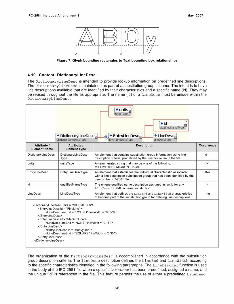
IPC-2581 includes Amendment 1 May 2007
Figure 7 Glyph bounding rectangles to Text bounding box relationships
4.10 Content: DictionaryLineDesc The DictionarylineDesc is intended to provide lookup information on predefined line descriptions. The DictionarylineDesc is maintained as part of a substitution group schema. The intent is to have line descriptions available that are identified by their characteristics and a specific name (id). They may be reused throughout the file as appropriate. The name (id) of a LineDesc must be unique within the DictionaryLineDesc.
Attribute /
Element Name Attribute /
Element Type Description Occurrence
DictionaryLineDesc DictionaryLineDesc Type
An element that contains substitution group information using line description criteria, predefined by the user for reuse in the file.
0-1
units unitsType An enumerated string that may be one of the following: MILLIMETER | MICRON | INCH.
1-1
EntryLineDesc EntryLineDescType An element that establishes the individual characteristic associated with a line description substitution group that has been identified by the user of the IPC-2581 file.
0-n
id qualifiedNameType The unique qualified name description assigned as an id for any LineDesc for XML schema substitution.
1-1
LineDesc LineDescType An element that defines the LineEnd and LineWidth characteristics to become part of the substitution group for defining line descriptions.
1-n
<DictionaryLineDesc units = "MILLIMETER"> <EntryLineDesc id = "FineLine"> <LineDesc lineEnd = "ROUND" lineWidth = "0.05"/> </EntryLineDesc> <EntryLineDesc id = "MediumLine"> <LineDesc lineEnd = "NONE" lineWidth = "0.15"/> </EntryLineDesc> <EntryLineDesc id = "HeavyLine"> <LineDesc lineEnd = "SQUARE" lineWidth = "0.30"/> </EntryLineDesc> </DictionaryLineDesc>
The organization of the DictionaryLineDesc is accomplished in accordance with the substitution group description criteria. The lineDesc description defines the LineEnd and LineWidth according to the specific characteristics identified in the following paragraphs. The LineDescRef function is used in the body of the IPC-2581 file when a specific LineDesc has been predefined, assigned a name, and the unique “id” is referenced in the file. This feature permits the use of either a predefined LineDesc,
68
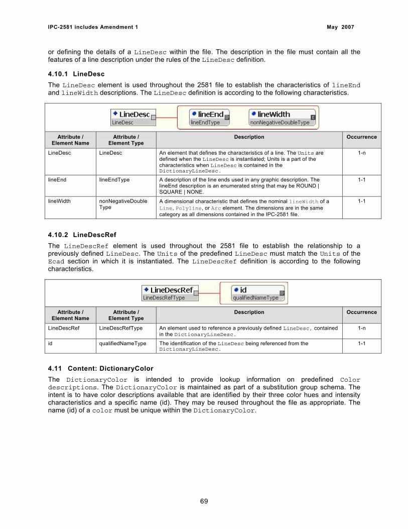
IPC-2581 includes Amendment 1 May 2007
or defining the details of a LineDesc within the file. The description in the file must contain all the features of a line description under the rules of the LineDesc definition.
4.10.1 LineDesc The LineDesc element is used throughout the 2581 file to establish the characteristics of lineEnd and lineWidth descriptions. The LineDesc definition is according to the following characteristics.
Attribute / Element Name
Attribute / Element Type
Description Occurrence
LineDesc LineDesc An element that defines the characteristics of a line. The Units are defined when the LineDesc is instantiated; Units is a part of the characteristics when LineDesc is contained in the DictionaryLineDesc.
1-n
lineEnd lineEndType A description of the line ends used in any graphic description. The lineEnd description is an enumerated string that may be ROUND | SQUARE | NONE.
1-1
lineWidth nonNegativeDouble Type
A dimensional characteristic that defines the nominal lineWidth of a Line, Polyline, or Arc element. The dimensions are in the same category as all dimensions contained in the IPC-2581 file.
1-1
4.10.2 LineDescRef The LineDescRef element is used throughout the 2581 file to establish the relationship to a previously defined LineDesc. The Units of the predefined LineDesc must match the Units of the Ecad section in which it is instantiated. The LineDescRef definition is according to the following characteristics.
Attribute / Element Name
Attribute / Element Type
Description Occurrence
LineDescRef LineDescRefType An element used to reference a previously defined LineDesc, contained in the DictionaryLineDesc.
1-n
id qualifiedNameType The identification of the LineDesc being referenced from the DictionaryLineDesc.
1-1
4.11 Content: DictionaryColor The DictionaryColor is intended to provide lookup information on predefined Color descriptions. The DictionaryColor is maintained as part of a substitution group schema. The intent is to have color descriptions available that are identified by their three color hues and intensity characteristics and a specific name (id). They may be reused throughout the file as appropriate. The name (id) of a color must be unique within the DictionaryColor.
69
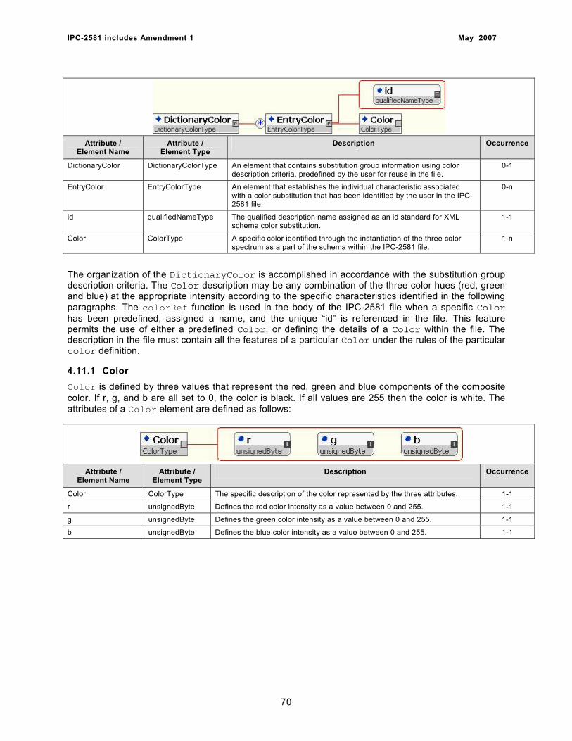
IPC-2581 includes Amendment 1 May 2007
Attribute /
Element Name Attribute /
Element Type Description Occurrence
DictionaryColor DictionaryColorType An element that contains substitution group information using color description criteria, predefined by the user for reuse in the file.
0-1
EntryColor EntryColorType An element that establishes the individual characteristic associated with a color substitution that has been identified by the user in the IPC-2581 file.
0-n
id qualifiedNameType The qualified description name assigned as an id standard for XML schema color substitution.
1-1
Color ColorType A specific color identified through the instantiation of the three color spectrum as a part of the schema within the IPC-2581 file.
1-n
The organization of the DictionaryColor is accomplished in accordance with the substitution group description criteria. The Color description may be any combination of the three color hues (red, green and blue) at the appropriate intensity according to the specific characteristics identified in the following paragraphs. The colorRef function is used in the body of the IPC-2581 file when a specific Color has been predefined, assigned a name, and the unique “id” is referenced in the file. This feature permits the use of either a predefined Color, or defining the details of a Color within the file. The description in the file must contain all the features of a particular Color under the rules of the particular color definition.
4.11.1 Color Color is defined by three values that represent the red, green and blue components of the composite color. If r, g, and b are all set to 0, the color is black. If all values are 255 then the color is white. The attributes of a Color element are defined as follows:
Attribute / Element Name
Attribute / Element Type
Description Occurrence
Color ColorType The specific description of the color represented by the three attributes. 1-1
r unsignedByte Defines the red color intensity as a value between 0 and 255. 1-1
g unsignedByte Defines the green color intensity as a value between 0 and 255. 1-1
b unsignedByte Defines the blue color intensity as a value between 0 and 255. 1-1
70
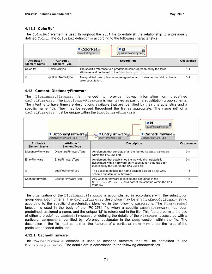
IPC-2581 includes Amendment 1 May 2007
4.11.2 ColorRef The ColorRef element is used throughout the 2581 file to establish the relationship to a previously defined Color. The ColorRef definition is according to the following characteristics.
Attribute / Element Name
Attribute / Element Type
Description Occurrence
ColorRef ColorRefType The specific reference to a predefined color represented by the three attributes and contained in the DictionaryColor.
1-1
id qualifiedNameType The qualified description name assigned as an id standard for XML schema color substitution.
1-1
4.12 Content: DictionaryFirmware The DictionaryFirmware is intended to provide lookup information on predefined CachedFirmware. The DictionaryFirmware is maintained as part of a substitution group schema. The intent is to have firmware descriptions available that are identified by their characteristics and a specific name (id). They may be reused throughout the file as appropriate. The name (id) of a CachedFirmware must be unique within the DictionaryFirmware.
Attribute / Element Name
Attribute / Element Type
Description Occurrence
DictionaryFirmware DictionaryFirmwareType An element that consists of all the named CachedFirmware within the IPC-2581 file.
0-n
EntryFirmware EntryFirmwareType An element that establishes the individual characteristic associated with a Firmware entry substitution that has been identified by the user in the IPC-2581 file.
0-n
id qualifiedNameType The qualified description name assigned as an id for XML schema substitution of firmware.
1-1
CachedFirmware CachedFirmwareType Any CachedFirmware identified and contained in the DictionaryFirmware as a part of the schema within the IPC-2581 file.
1-n
The organization of the DictionaryFirmware is accomplished in accordance with the substitution group description criteria. The CachedFirmware description may be any hexEncodedBinary string according to the specific characteristics identified in the following paragraphs. The FirmwareRef function is used in the body of the IPC-2581 file when a specific CachedFirmware has been predefined, assigned a name, and the unique “id” is referenced in the file. This feature permits the use of either a predefined CachedFirmware, or defining the details of the Firmware associated with a particular Component identified by reference designator in the Step section within the file. The description in the file must contain all the features of a particular Firmware under the rules of the particular encoded definition.
4.12.1 CachedFirmware The CachedFirmware element is used to describe firmware that will be contained in the DictionaryFirmware. The details are in accordance to the following characteristics.
71
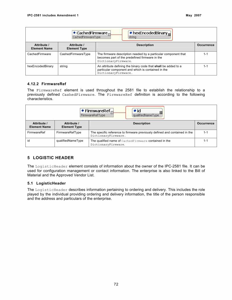
IPC-2581 includes Amendment 1 May 2007
Attribute / Element Name
Attribute / Element Type
Description Occurrence
CachedFirmware CashedFirmwareType The firmware description needed by a particular component that becomes part of the predefined firmware in the DictionaryFirmware.
1-1
hexEncodedBinary string An attribute defining the binary code that shall be added to a particular component and which is contained in the DictionaryFirmware.
1-1
4.12.2 FirmwareRef The FirmwareRef element is used throughout the 2581 file to establish the relationship to a previously defined CashedFirmware. The FirmwareRef definition is according to the following characteristics.
Attribute / Element Name
Attribute / Element Type
Description Occurrence
FirmwareRef FirmwareRefType The specific reference to firmware previously defined and contained in the DictionaryFirmware.
1-1
id qualifiedNameType The qualified name of CachedFirmware contained in the DictionaryFirmware.
1-1
5 LOGISTIC HEADER
The LogisticHeader element consists of information about the owner of the IPC-2581 file. It can be used for configuration management or contact information. The enterprise is also linked to the Bill of Material and the Approved Vendor List.
5.1 LogisticHeader The LogisticHeader describes information pertaining to ordering and delivery. This includes the role played by the individual providing ordering and delivery information, the title of the person responsible and the address and particulars of the enterprise.
72
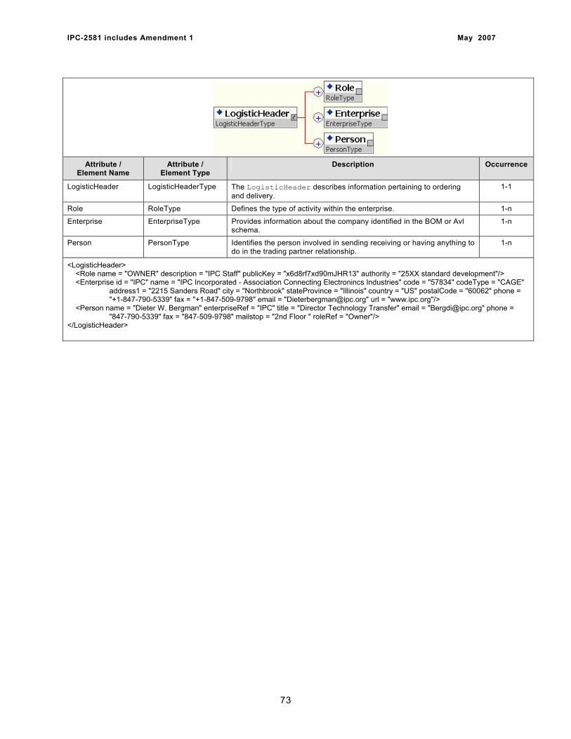
IPC-2581 includes Amendment 1 May 2007
Attribute / Element Name
Attribute / Element Type
Description Occurrence
LogisticHeader LogisticHeaderType The LogisticHeader describes information pertaining to ordering and delivery.
1-1
Role RoleType Defines the type of activity within the enterprise. 1-n
Enterprise EnterpriseType Provides information about the company identified in the BOM or Avl schema.
1-n
Person PersonType Identifies the person involved in sending receiving or having anything to do in the trading partner relationship.
1-n
<LogisticHeader> <Role name = "OWNER" description = "IPC Staff" publicKey = "x6d8rf7xd90mJHR13" authority = "25XX standard development"/> <Enterprise id = "IPC" name = "IPC Incorporated - Association Connecting Electronincs Industries" code = "57834" codeType = "CAGE" address1 = "2215 Sanders Road" city = "Northbrook" stateProvince = "Illinois" country = "US" postalCode = "60062" phone = "+1-847-790-5339" fax = "+1-847-509-9798" email = "[email protected]" url = "www.ipc.org"/> <Person name = "Dieter W. Bergman" enterpriseRef = "IPC" title = "Director Technology Transfer" email = "[email protected]" phone = "847-790-5339" fax = "847-509-9798" mailstop = "2nd Floor " roleRef = "Owner"/> </LogisticHeader>
73

IPC-2581 includes Amendment 1 May 2007
5.2 Role A Role element declares a type of activity within an Enterprise. The attribute values of the Role based on the requirements of the activities performed by the role.
Attribute / Element Name
Attribute / Element Type
Description Occurrence
Role RoleType Defines the type of activity within the enterprise. 1-n
name string The name attribute defines a globally unique identification of the role within an enterprise The description uniquely identifies a role type used by the enterprise. The name is a roleType (a restricted xsd:string) that must be unique within the global (top-level) namespace of the IPC-2581 file. The standard IPC role types are defined as follows: SENDER: Identifies the person sending out the IPC-2581 file. OWNER: Identifies the person who maintains the configuration management of the IPC-2581 file and has the right to increment the file history number of the IPC-2581 file. RECEIVER: Identifies the person receiving the IPC-2581 file. DESIGNER: Identifies the designer of the product described in the IPC-2581 file. ENGINEER: Identifies the engineer who is responsible for the product described in the IPC-2581 file. BUYER: Identifies the person who is responsible for payment. CUSTOMERSERVICE: Identifies the customer service representative who is responsible for the account. DELIVERTO: Identifies the person in the receiving department who takes possession of the shipment in the name of the enterprise. BILLTO: Identifies the person in the billing or purchasing department to whom the billing should be addressed. OTHER: Any other name however completing the description attribute is recommended
1-1
description string The description attribute defines a role within an enterprise. (The description is optional if the IPC definition is to be used.)
0-1
publicKey base64Binary The publicKey attribute of a role holds the public encryption key if one exists for the role. The key is base64 encoded. (See IETF RFC 1421 for the base64 algorithm) If a role publicKey is present it can be used instead of a Person/publicKey to encrypt data. The role’s publicKey is used to encrypt data so only that someone with access to the role’s private key can access the data.
0-1
authority string The access level associated with this role as defined by the system referenced by externalConfigurationControlEntryPoint
0-1
<LogisticHeader> <Role name = “CircuitDesign” description = “ENGINEER”/> <Role name = “LayoutPerson” description = “ENGINEER”/> <Role name = “PurchasingNo1” description = “BUYER”/> <Role name = “LayoutEngineer” description = “DESIGNER”/> </LogisticHeader>
74
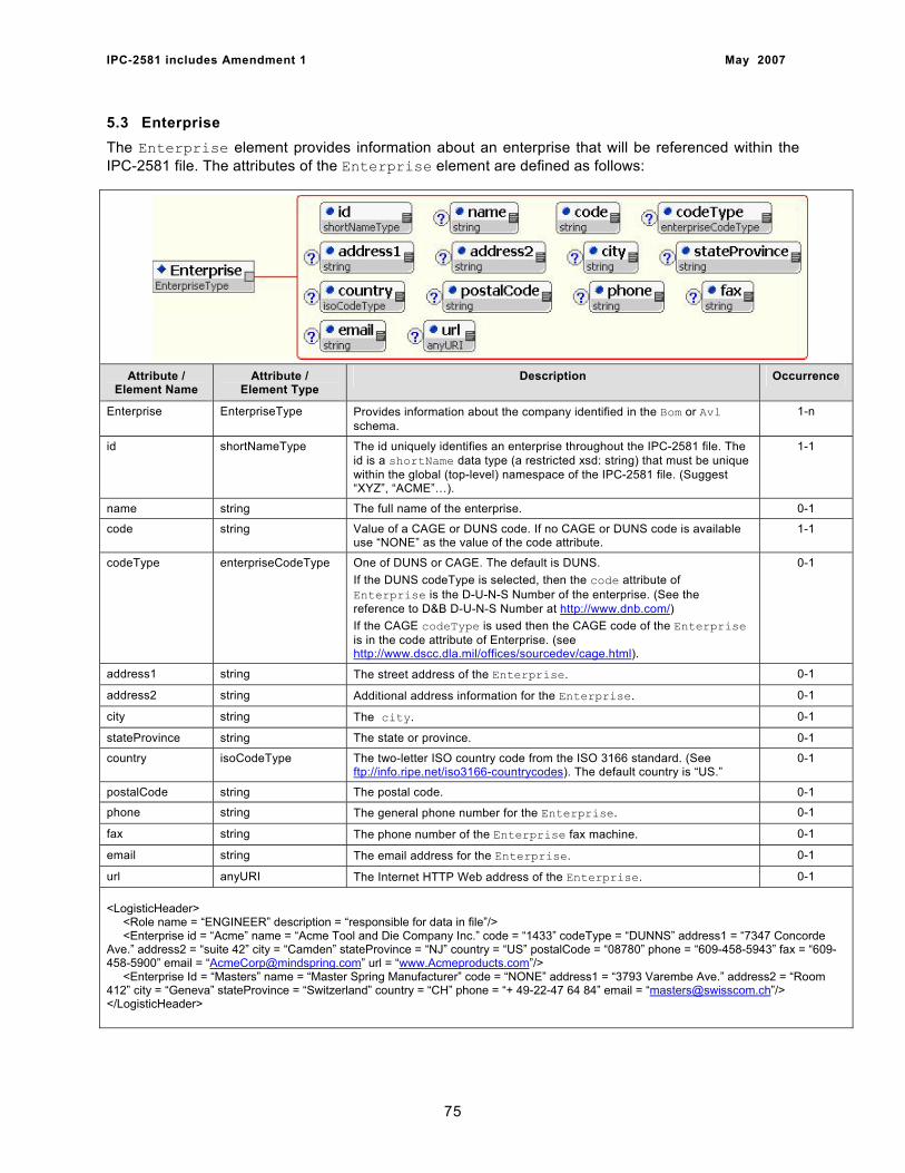
IPC-2581 includes Amendment 1 May 2007
5.3 Enterprise The Enterprise element provides information about an enterprise that will be referenced within the IPC-2581 file. The attributes of the Enterprise element are defined as follows:
Attribute / Element Name
Attribute / Element Type
Description Occurrence
Enterprise EnterpriseType Provides information about the company identified in the Bom or Avl schema.
1-n
id shortNameType The id uniquely identifies an enterprise throughout the IPC-2581 file. The id is a shortName data type (a restricted xsd: string) that must be unique within the global (top-level) namespace of the IPC-2581 file. (Suggest “XYZ”, “ACME”…).
1-1
name string The full name of the enterprise. 0-1
code string Value of a CAGE or DUNS code. If no CAGE or DUNS code is available use “NONE” as the value of the code attribute.
1-1
codeType enterpriseCodeType One of DUNS or CAGE. The default is DUNS. If the DUNS codeType is selected, then the code attribute of Enterprise is the D-U-N-S Number of the enterprise. (See the reference to D&B D-U-N-S Number at http://www.dnb.com/) If the CAGE codeType is used then the CAGE code of the Enterprise is in the code attribute of Enterprise. (see http://www.dscc.dla.mil/offices/sourcedev/cage.html).
0-1
address1 string The street address of the Enterprise. 0-1
address2 string Additional address information for the Enterprise. 0-1
city string The city. 0-1
stateProvince string The state or province. 0-1
country isoCodeType The two-letter ISO country code from the ISO 3166 standard. (See ftp://info.ripe.net/iso3166-countrycodes). The default country is “US.”
0-1
postalCode string The postal code. 0-1
phone string The general phone number for the Enterprise. 0-1
fax string The phone number of the Enterprise fax machine. 0-1
email string The email address for the Enterprise. 0-1
url anyURI The Internet HTTP Web address of the Enterprise. 0-1 <LogisticHeader> <Role name = “ENGINEER” description = “responsible for data in file”/> <Enterprise id = “Acme” name = “Acme Tool and Die Company Inc.” code = “1433” codeType = “DUNNS” address1 = “7347 Concorde Ave.” address2 = “suite 42” city = “Camden” stateProvince = “NJ” country = “US” postalCode = “08780” phone = “609-458-5943” fax = “609-458-5900” email = “[email protected]” url = “www.Acmeproducts.com”/> <Enterprise Id = “Masters” name = “Master Spring Manufacturer” code = “NONE” address1 = “3793 Varembe Ave.” address2 = “Room 412” city = “Geneva” stateProvince = “Switzerland” country = “CH” phone = “+ 49-22-47 64 84” email = “[email protected]”/> </LogisticHeader>
75
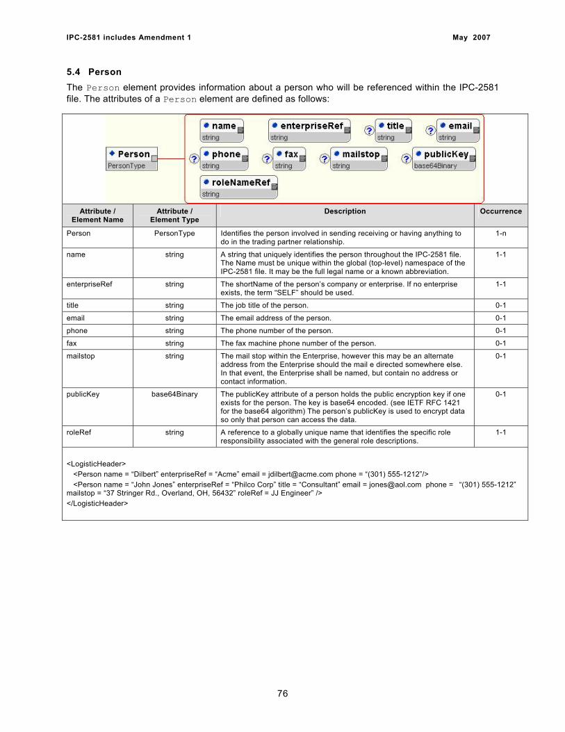
IPC-2581 includes Amendment 1 May 2007
5.4 Person The Person element provides information about a person who will be referenced within the IPC-2581 file. The attributes of a Person element are defined as follows:
Attribute /
Element Name Attribute /
Element Type Description Occurrence
Person PersonType Identifies the person involved in sending receiving or having anything to do in the trading partner relationship.
1-n
name string A string that uniquely identifies the person throughout the IPC-2581 file. The Name must be unique within the global (top-level) namespace of the IPC-2581 file. It may be the full legal name or a known abbreviation.
1-1
enterpriseRef string The shortName of the person’s company or enterprise. If no enterprise exists, the term “SELF” should be used.
1-1
title string The job title of the person. 0-1
email string The email address of the person. 0-1
phone string The phone number of the person. 0-1
fax string The fax machine phone number of the person. 0-1
mailstop string The mail stop within the Enterprise, however this may be an alternate address from the Enterprise should the mail e directed somewhere else. In that event, the Enterprise shall be named, but contain no address or contact information.
0-1
publicKey base64Binary The publicKey attribute of a person holds the public encryption key if one exists for the person. The key is base64 encoded. (see IETF RFC 1421 for the base64 algorithm) The person’s publicKey is used to encrypt data so only that person can access the data.
0-1
roleRef string A reference to a globally unique name that identifies the specific role responsibility associated with the general role descriptions.
1-1
<LogisticHeader> <Person name = “Dilbert” enterpriseRef = “Acme” email = [email protected] phone = “(301) 555-1212”/> <Person name = “John Jones” enterpriseRef = “Philco Corp” title = “Consultant” email = [email protected] phone = “(301) 555-1212” mailstop = “37 Stringer Rd., Overland, OH, 56432” roleRef = JJ Engineer” /> </LogisticHeader>
76
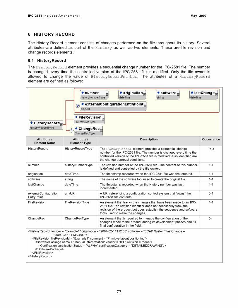
IPC-2581 includes Amendment 1 May 2007
6 HISTORY RECORD
The History Record element consists of changes performed on the file throughout its history. Several attributes are defined as part of the History as well as two elements. These are file revision and change records elements.
6.1 HistoryRecord The HistoryRecord element provides a sequential change number for the IPC-2581 file. The number is changed every time the controlled version of the IPC-2581 file is modified. Only the file owner is allowed to change the value of HistoryRecord/number. The attributes of a HistoryRecord element are defined as follows:
Attribute /
Element Name Attribute /
Element Type Description Occurrence
HistoryRecord HistoryRecordType The HistoryRecord element provides a sequential change number for the IPC-2581 file. The number is changed every time the controlled version of the IPC-2581 file is modified. Also identified are the change approval conditions.
1-1
number historyNumberType The revision number of the IPC-2581 file. The content of this number is defined and controlled by the file owner.
1-1
origination dateTime The timestamp recorded when the IPC-2581 file was first created. 1-1
software string The name of the software tool used to create the original file. 1-1
lastChange dateTime The timestamp recorded when the History number was last incremented.
1-1
externalConfiguration EntryPoint
anyURI A URI referencing a configuration control system that “owns” the IPC-2581 file contents.
0-1
FileRevision FileRevisionType An element that tracks the changes that have been made to an IPC-2581 file. The revision identifier does not necessarily track the revision of the product but does establish the sequence and software tools used to make the changes.
1-1
ChangeRec ChangeRecType An element that is required to manage the configuration of the changes made to the product during its development phases and its final configuration in the field.
0-n
<HistoryRecord number = "Example1" origination = "2004-02-11T12:53" software = "ECAD System" lastChange = "2004-02-13T13:24:00"> <FileRevision fileRevisionId = "Example1" comment = "Primitive layout positioning"> <SoftwarePackage name = "Manual Interpretation" vendor = "IPC" revision = "none"> <Certification certificationStatus = "ALPHA" certificationCategory = "DETAILEDDRAWING"/> </SoftwarePackage> </FileRevision> </HistoryRecord>
77
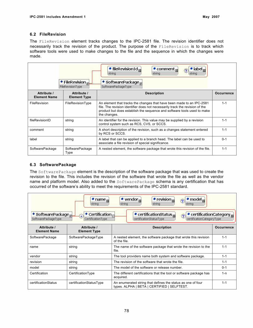
IPC-2581 includes Amendment 1 May 2007
6.2 FileRevision The FileRevision element tracks changes to the IPC-2581 file. The revision identifier does not necessarily track the revision of the product. The purpose of the FileRevision is to track which software tools were used to make changes to the file and the sequence in which the changes were made.
Attribute / Element Name
Attribute / Element Type
Description Occurrence
FileRevision FileRevisionType An element that tracks the changes that have been made to an IPC-2581 file. The revision identifier does not necessarily track the revision of the product but does establish the sequence and software tools used to make the changes.
1-1
fileRevisionID string An identifier for the revision. This value may be supplied by a revision control system such as RCS, CVS, or SCCS.
1-1
comment string A short description of the revision, such as a changes statement entered by RCS or SCCS.
1-1
label string A label that can be applied to a branch head. The label can be used to associate a file revision of special significance.
0-1
SoftwarePackage SoftwarePackage Type
A nested element, the software package that wrote this revision of the file. 1-1
6.3 SoftwarePackage The SoftwarePackage element is the description of the software package that was used to create the revision to the file. This includes the revision of the software that wrote the file as well as the vendor name and platform model. Also added to the SoftwarePackage schema is any certification that has occurred of the software’s ability to meet the requirements of the IPC-2581 standard.
Attribute / Element Name
Attribute / Element Type
Description Occurrence
SoftwarePackage SoftwarePackageType A nested element, the software package that wrote this revision of the file.
1-1
name string The name of the software package that wrote the revision to the file.
1-1
vendor string The tool providers name both system and software package. 1-1
revision string The revision of the software that wrote the file. 1-1
model string The model of the software or release number. 0-1
Certification CertificationType The different certifications that the tool or software package has acquired.
1-n
certificationStatus certificationStatusType An enumerated string that defines the status as one of four types. ALPHA | BETA | CERTIFIED | SELFTEST.
1-1
78
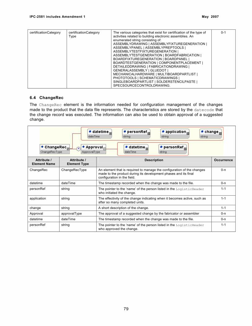
IPC-2581 includes Amendment 1 May 2007
certificationCategory certificationCategory Type
The various categories that exist for certification of the type of activities related to building electronic assemblies. An enumerated string consisting of: ASSEMBLYDRAWING | ASSEMBLYFIXTUREGENERATION | ASSEMBLYPANEL | ASSEMBLYPREPTOOLS | ASSEMBLYTESTFIXTUREGENERATION | ASSEMBLYTESTGENERATION | BOARDFABRICATION | BOARDFIXTUREGENERATION | BOARDPANEL | BOARDTESTGENERATION | COMPONENTPLACEMENT | DETAILEDDRAWING | FABRICATIONDRAWING | GENERALASSEMBLY | GLUEDOT | MECHANICALHARDWARE | MULTIBOARDPARTLIST | PHOTOTOOLS | SCHEMATICDRAWINGS | SINGLEBOARDPARTLIST | SOLDERSTENCILPASTE | SPECSOURCECONTROLDRAWING.
0-1
6.4 ChangeRec The ChangeRec element is the information needed for configuration management of the changes made to the product that the data file represents. The characteristics are stored by the datecode that the change record was executed. The information can also be used to obtain approval of a suggested change.
Attribute /
Element Name Attribute /
Element Type Description Occurrence
ChangeRec ChangeRecType An element that is required to manage the configuration of the changes made to the product during its development phases and its final configuration in the field.
0-n
datetime dateTime The timestamp recorded when the change was made to the file. 0-n
personRef string The pointer to the ‘name’ of the person listed in the LogisticHeader who initiated the change.
1-1
application string The effectivity of the change indicating when it becomes active, such as after so many completed units.
1-1
change string A short description of the change. 1-1
Approval approvalType The approval of a suggested change by the fabricator or assembler 0-n
datetime dateTime The timestamp recorded when the change was made to the file. 0-n
personRef string The pointer to the ‘name’ of the person listed in the LogisticHeader who approved the change.
1-1
79
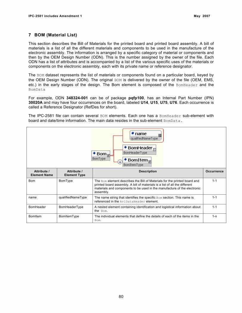
IPC-2581 includes Amendment 1 May 2007
7 BOM (Material List)
This section describes the Bill of Materials for the printed board and printed board assembly. A bill of materials is a list of all the different materials and components to be used in the manufacture of the electronic assembly. The information is arranged by a specific category of material or components and then by the OEM Design Number (ODN). This is the number assigned by the owner of the file. Each ODN has a list of attributes and is accompanied by a list of the various specific uses of the materials or components on the electronic assembly, each with its private name or reference designator.
The BOM dataset represents the list of materials or components found on a particular board, keyed by the OEM Design Number (ODN). The original BOM is delivered by the owner of the file (OEM, EMS, etc.) in the early stages of the design. The Bom element is composed of the BomHeader and the BomData
For example, ODN 348324-001 can be of package pqfp100, has an Internal Part Number (IPN) 30020A and may have four occurrences on the board, labeled U14, U15, U75, U76. Each occurrence is called a Reference Designator (RefDes for short).
The IPC-2581 file can contain several BOM elements. Each one has a BomHeader sub-element with board and date/time information. The main data resides in the sub-element BomData.
Attribute / Element Name
Attribute / Element Type
Description Occurrence
Bom BomType The Bom element describes the Bill of Materials for the printed board and printed board assembly. A bill of materials is a list of all the different materials and components to be used in the manufacture of the electronic assembly.
1-1
name qualifiedNameType The name string that identifies the specific Bom section. This name is referenced in the AvlDataHeader element.
1-1
BomHeader BomHeaderType A nested element containing identification and logistical information about the Bom.
1-1
BomItem BomItemType The individual elements that define the details of each of the items in the Bom.
1-n
80
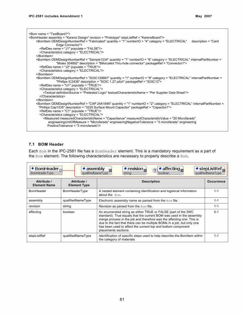
IPC-2581 includes Amendment 1 May 2007
<Bom name = "TestBoard1"> <BomHeader assembly = "Karens Design" revision = "Prototype" stepListRef = "KarensBoard"/> <BomItem OEMDesignNumberRef = "Fabricated" quantity = "1" numberIO = "4" category = "ELECTRICAL" description = "Card Edge Connector"> <RefDes name = "J1" populate = "FALSE"/> <Characteristics category = "ELECTRICAL"/> </BomItem> <BomItem OEMDesignNumberRef = "Sample1234" quantity = "1" numberIO = "8" category = "ELECTRICAL" internalPartNumber = "Molex 354892" description = "Biforcated Thru-hole connector" packageRef = "Connector1"> <RefDes name = "J2" populate = "TRUE"/> <Characteristics category = "ELECTRICAL"/> </BomItem> <BomItem OEMDesignNumberRef = "SOIC129867" quantity = "1" numberIO = "8" category = "ELECTRICAL" internalPartNumber = "Phillips IC2436" description = "SOIC 1.27 pitch" packageRef = "SOIC12"> <RefDes name = "U1" populate = "TRUE"/> <Characteristics category = "ELECTRICAL"> <Textual definitionSource = "Pretested Logic" textualCharacteristicName = "Per Supplier Data Sheet"/> </Characteristics> </BomItem> <BomItem OEMDesignNumberRef = "CAP 24A1846" quantity = "1" numberIO = "2" category = "ELECTRICAL" internalPartNumber = "Phillips Cap1235" description = "3225 Surface Mount Capacitor" packageRef = "Capacitor1"> <RefDes name = "C1" populate = "TRUE"/> <Characteristics category = "ELECTRICAL"> <Measured measuredCharacteristicName = "Capacitance" measuredCharacteristicValue = "20 Microfarads" engineeringUnitOfMeasure = "Microfarads" engineeringNegativeTolerance = "3 microfarads" engineering PositiveTolerance = "3 microfarads"/>
7.1 BOM Header Each Bom in the IPC-2581 file has a BomHeader element. This is a mandatory requirement as a part of the Bom element. The following characteristics are necessary to properly describe a Bom.
Attribute / Element Name
Attribute / Element Type
Description Occurrence
BomHeader BomHeaderType A nested element containing identification and logistical information about the Bom.
1-1
assembly qualifiedNameType Electronic assembly name as parsed from the Bom file. 1-1
revision string Revision as parsed from the Bom file. 1-1
affecting boolean An enumerated string as either TRUE or FALSE (part of the 3WC standard). True equals that the current BOM was used in the assembly merge process in the job and therefore was the affecting one. This is due to the fact that there can be multiple BOMs in a job, but only one has been used to affect the current top and bottom component placements sections.
0-1
stepListRef qualifiedNameType Identification of specific steps used to help describe the BomItem within the category of materials
1-1
81
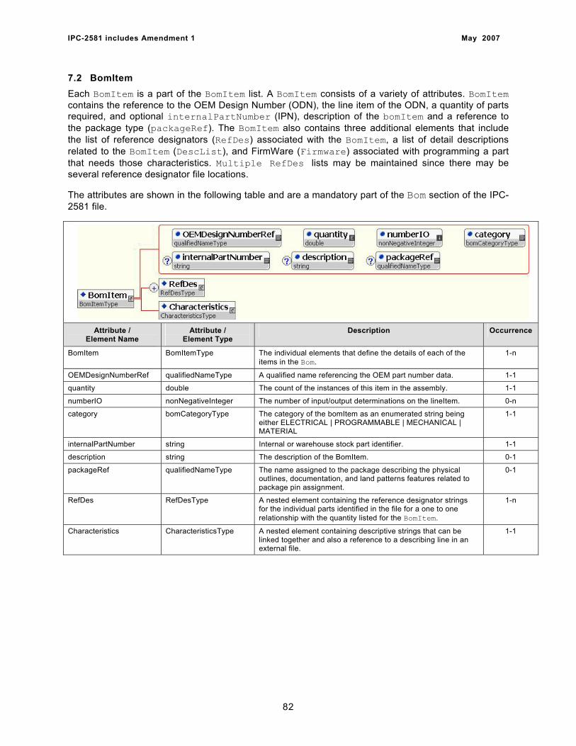
IPC-2581 includes Amendment 1 May 2007
7.2 BomItem Each BomItem is a part of the BomItem list. A BomItem consists of a variety of attributes. BomItem contains the reference to the OEM Design Number (ODN), the line item of the ODN, a quantity of parts required, and optional internalPartNumber (IPN), description of the bomItem and a reference to the package type (packageRef). The BomItem also contains three additional elements that include the list of reference designators (RefDes) associated with the BomItem, a list of detail descriptions related to the BomItem (DescList), and FirmWare (Firmware) associated with programming a part that needs those characteristics. Multiple RefDes lists may be maintained since there may be several reference designator file locations.
The attributes are shown in the following table and are a mandatory part of the Bom section of the IPC-2581 file.
Attribute / Element Name
Attribute / Element Type
Description Occurrence
BomItem BomItemType The individual elements that define the details of each of the items in the Bom.
1-n
OEMDesignNumberRef qualifiedNameType A qualified name referencing the OEM part number data. 1-1
quantity double The count of the instances of this item in the assembly. 1-1
numberIO nonNegativeInteger The number of input/output determinations on the lineItem. 0-n
category bomCategoryType The category of the bomItem as an enumerated string being either ELECTRICAL | PROGRAMMABLE | MECHANICAL | MATERIAL
1-1
internalPartNumber string Internal or warehouse stock part identifier. 1-1
description string The description of the BomItem. 0-1
packageRef qualifiedNameType The name assigned to the package describing the physical outlines, documentation, and land patterns features related to package pin assignment.
0-1
RefDes RefDesType A nested element containing the reference designator strings for the individual parts identified in the file for a one to one relationship with the quantity listed for the BomItem.
1-n
Characteristics CharacteristicsType A nested element containing descriptive strings that can be linked together and also a reference to a describing line in an external file.
1-1
82
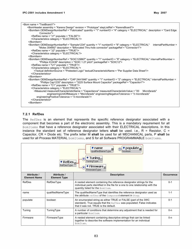
IPC-2581 includes Amendment 1 May 2007
<Bom name = "TestBoard1"> <BomHeader assembly = "Karens Design" revision = "Prototype" stepListRef = "KarensBoard"/>
<BomItem OEMDesignNumberRef = "Fabricated" quantity = "1" numberIO = "4" category = "ELECTRICAL" description = "Card Edge Connector"> <RefDes name = "J1" populate = "FALSE"/> <Characteristics category = "ELECTRICAL"/> </BomItem> <BomItem OEMDesignNumberRef = "Sample1234" quantity = "1" numberIO = "8" category = "ELECTRICAL" internalPartNumber = "Molex 354892" description = "Biforcated Thru-hole connector" packageRef = "Connector1"> <RefDes name = "J2" populate = "TRUE"/> <Characteristics category = "ELECTRICAL"/> </BomItem> <BomItem OEMDesignNumberRef = "SOIC129867" quantity = "1" numberIO = "8" category = "ELECTRICAL" internalPartNumber = "Phillips IC2436" description = "SOIC 1.27 pitch" packageRef = "SOIC12"> <RefDes name = "U1" populate = "TRUE"/> <Characteristics category = "ELECTRICAL"> <Textual definitionSource = "Pretested Logic" textualCharacteristicName = "Per Supplier Data Sheet"/> </Characteristics> </BomItem> <BomItem OEMDesignNumberRef = "CAP 24A1846" quantity = "1" numberIO = "2" category = "ELECTRICAL" internalPartNumber = "Phillips Cap1235" description = "3225 Surface Mount Capacitor" packageRef = "Capacitor1"> <RefDes name = "C1" populate = "TRUE"/> <Characteristics category = "ELECTRICAL"> <Measured measuredCharacteristicName = "Capacitance" measuredCharacteristicValue = "20 Microfarads" engineeringUnitOfMeasure = "Microfarads" engineeringNegativeTolerance = "3 microfarads" engineeringPositiveTolerance = "3 microfarads"/> </Characteristics> </BomItem> 7.2.1 RefDes The RefDes is an element that represents the specific reference designator associated with a component that becomes a part of the electronic assembly. This is a mandatory requirement for all BomItems that have a reference designator associated with their ELECTRICAL descriptions. In this instance the standard set of reference designator letters shall be used. i.e., R = Resistor, C = Capacitor, CR = Diode etc. The prefix letter M shall be used for all MECHANICAL parts, P shall be used for all Process MATERIAL bomItems, and S for all Software PROGRAMMABLE bomItems.
Attribute / Element Name
Attribute / Element Type
Description Occurrence
RefDes RefDesType A nested element containing the reference designator strings for the individual parts identified in the file for a one to one relationship with the quantity listed for the BomItem.
0-1
name qualifiedNameType The qualifiedNameType that identifies the reference designator used as the attribute refDes of the Component element in Step.
1-1
populate boolean An enumerated string as either TRUE or FALSE (part of the 3WC standard). True equals that the RefDes was populated; False indicates that it was not. TRUE is the default.
0-1
Tuning TuningType A number of conditions that determine any adjustment that is needed for a particular BomItem.
0-n
Firmware FirmwareType A nested element containing descriptive strings that can be linked together to describe the software implementation for an individual BomItem.
0-n
83
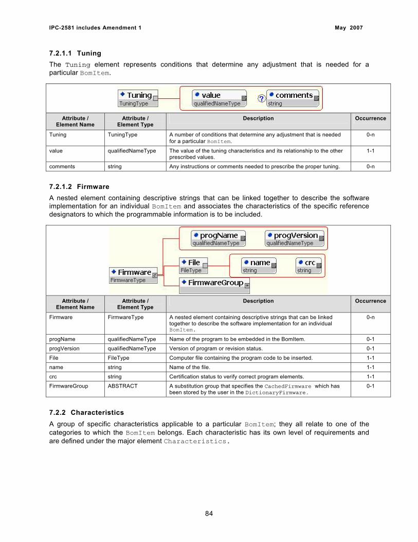
IPC-2581 includes Amendment 1 May 2007
7.2.1.1 Tuning The Tuning element represents conditions that determine any adjustment that is needed for a particular BomItem.
Attribute / Element Name
Attribute / Element Type
Description Occurrence
Tuning TuningType A number of conditions that determine any adjustment that is needed for a particular BomItem.
0-n
value qualifiedNameType The value of the tuning characteristics and its relationship to the other prescribed values.
1-1
comments string Any instructions or comments needed to prescribe the proper tuning. 0-n
7.2.1.2 Firmware A nested element containing descriptive strings that can be linked together to describe the software implementation for an individual BomItem and associates the characteristics of the specific reference designators to which the programmable information is to be included.
Attribute /
Element Name Attribute /
Element Type Description Occurrence
Firmware FirmwareType A nested element containing descriptive strings that can be linked together to describe the software implementation for an individual BomItem.
0-n
progName qualifiedNameType Name of the program to be embedded in the BomItem. 0-1
progVersion qualifiedNameType Version of program or revision status. 0-1
File FileType Computer file containing the program code to be inserted. 1-1
name string Name of the file. 1-1
crc string Certification status to verify correct program elements. 1-1
FirmwareGroup ABSTRACT A substitution group that specifies the CachedFirmware which has been stored by the user in the DictionaryFirmware.
0-1
7.2.2 Characteristics A group of specific characteristics applicable to a particular BomItem; they all relate to one of the categories to which the BomItem belongs. Each characteristic has its own level of requirements and are defined under the major element Characteristics.
84
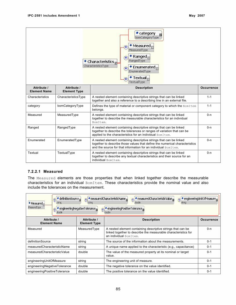
IPC-2581 includes Amendment 1 May 2007
Attribute /
Element Name Attribute /
Element Type Description Occurrence
Characteristics CharacteristicsType A nested element containing descriptive strings that can be linked together and also a reference to a describing line in an external file.
1-1
category bomCategoryType Defines the type of material or component category to which the BomItem belongs.
1-1
Measured MeasuredType A nested element containing descriptive strings that can be linked together to describe the measurable characteristics for an individual BomItem.
0-n
Ranged RangedType A nested element containing descriptive strings that can be linked together to describe the tolerances or ranges of variation that can be applied to the characteristics for an individual BomItem.
0-n
Enumerated EnumeratedType A nested element containing descriptive strings that can be linked together to describe those values that define the numerical characteristics and the source for that information for an individual BomItem.
0-n
Textual TextualType A nested element containing descriptive strings that can be linked together to describe any textual characteristics and their source for an individual BomItem.
0-n
7.2.2.1 Measured The Measured elements are those properties that when linked together describe the measurable characteristics for an individual BomItem. These characteristics provide the nominal value and also include the tolerances on the measurement.
Attribute / Element Name
Attribute / Element Type
Description Occurrence
Measured MeasuredType A nested element containing descriptive strings that can be linked together to describe the measurable characteristics for an individual BomItem.
0-n
definitionSource string The source of the information about the measurements. 0-1
measuredCharacteristicName string A unique name applied to the characteristic (e.g., capacitance) 0-1
measuredCharacteristicValue double The value of the measured property at its nominal or target value.
0-1
engineeringUnitOfMeasure string The engineering unit of measure. 0-1
engineeringNegativeTolerance double The negative tolerance on the value identified. 0-1
engineeringPositiveTolerance double The positive tolerance on the value identified. 0-1
85
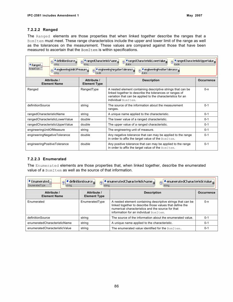
IPC-2581 includes Amendment 1 May 2007
7.2.2.2 Ranged The Ranged elements are those properties that when linked together describe the ranges that a BomItem must meet. These range characteristics include the upper and lower limit of the range as well as the tolerances on the measurement. These values are compared against those that have been measured to ascertain that the BomItem is within specifications.
Attribute / Element Name
Attribute / Element Type
Description Occurrence
Ranged RangedType A nested element containing descriptive strings that can be linked together to describe the tolerances or ranges of variation that can be applied to the characteristics for an individual BomItem.
0-n
definitionSource string The source of the information about the measurement ranges.
0-1
rangedCharacteristicName string A unique name applied to the characteristic. 0-1
rangedCharacteristicLowerValue double The lower value of a ranged characteristic. 0-1
rangedCharacteristicUpperValue double The upper value of a ranged characteristic. 0-1
engineeringUnitOfMeasure string The engineering unit of measure. 0-1
engineeringNegativeTolerance double Any negative tolerance that can may be applied to the range in order to affix the target value of the BomItem.
0-1
engineeringPositiveTolerance double Any positive tolerance that can may be applied to the range in order to affix the target value of the BomItem.
0-1
7.2.2.3 Enumerated The Enumerated elements are those properties that, when linked together, describe the enumerated value of a BomItem as well as the source of that information.
Attribute /
Element Name Attribute /
Element Type Description Occurrence
Enumerated EnumeratedType A nested element containing descriptive strings that can be linked together to describe those values that define the numerical characteristics and the source for that information for an individual BomItem.
0-n
definitionSource string The source of the information about the enumerated value. 0-1
enumeratedCharacteristicName string A unique name applied to the characteristic. 0-1
enumeratedCharacteristicValue string The enumerated value identified for the BomItem. 0-1
86
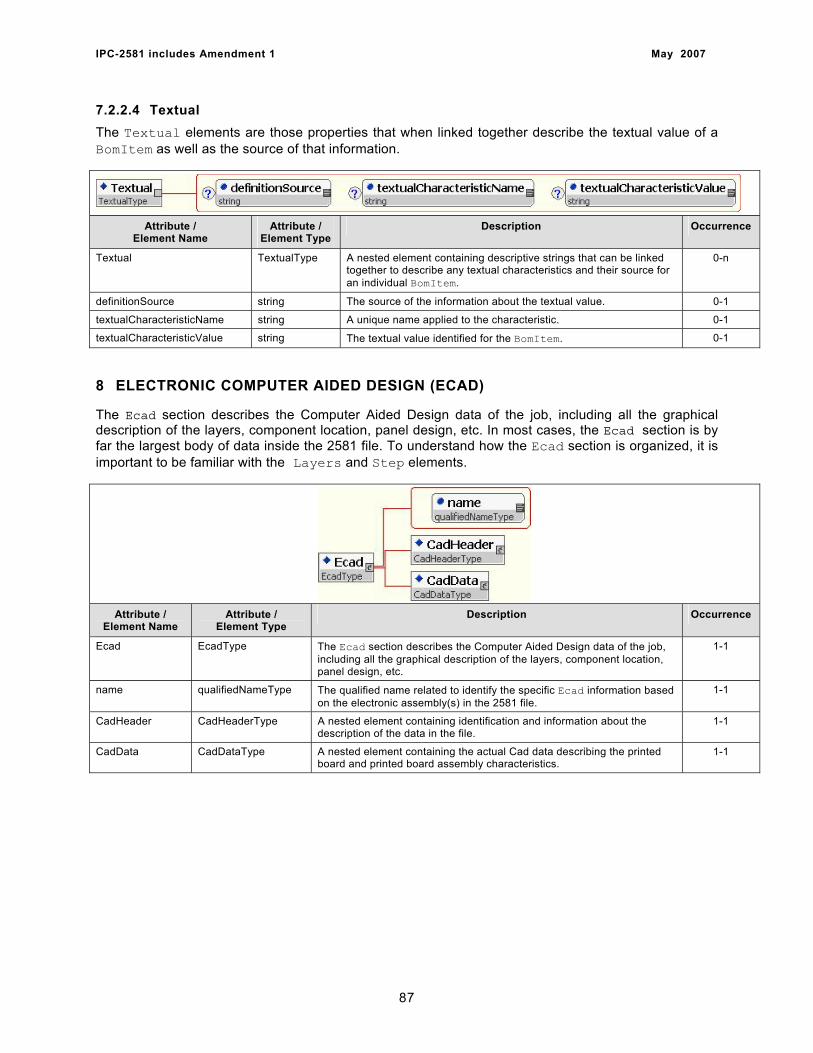
IPC-2581 includes Amendment 1 May 2007
7.2.2.4 Textual The Textual elements are those properties that when linked together describe the textual value of a BomItem as well as the source of that information.
Attribute /
Element Name Attribute /
Element Type Description Occurrence
Textual TextualType A nested element containing descriptive strings that can be linked together to describe any textual characteristics and their source for an individual BomItem.
0-n
definitionSource string The source of the information about the textual value. 0-1
textualCharacteristicName string A unique name applied to the characteristic. 0-1
textualCharacteristicValue string The textual value identified for the BomItem. 0-1
8 ELECTRONIC COMPUTER AIDED DESIGN (ECAD)
The Ecad section describes the Computer Aided Design data of the job, including all the graphical description of the layers, component location, panel design, etc. In most cases, the Ecad section is by far the largest body of data inside the 2581 file. To understand how the Ecad section is organized, it is important to be familiar with the Layers and Step elements.
Attribute /
Element Name Attribute /
Element Type Description Occurrence
Ecad EcadType The Ecad section describes the Computer Aided Design data of the job, including all the graphical description of the layers, component location, panel design, etc.
1-1
name qualifiedNameType The qualified name related to identify the specific Ecad information based on the electronic assembly(s) in the 2581 file.
1-1
CadHeader CadHeaderType A nested element containing identification and information about the description of the data in the file.
1-1
CadData CadDataType A nested element containing the actual Cad data describing the printed board and printed board assembly characteristics.
1-1
87
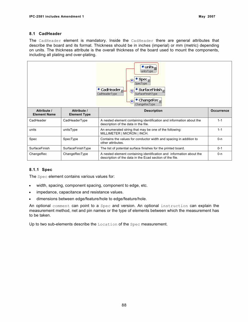
IPC-2581 includes Amendment 1 May 2007
8.1 CadHeader The CadHeader element is mandatory. Inside the CadHeader there are general attributes that describe the board and its format. Thickness should be in inches (imperial) or mm (metric) depending on units. The thickness attribute is the overall thickness of the board used to mount the components, including all plating and over-plating.
Attribute / Element Name
Attribute / Element Type
Description Occurrence
CadHeader CadHeaderType A nested element containing identification and information about the description of the data in the file.
1-1
units unitsType An enumerated string that may be one of the following: MILLIMETER | MICRON | INCH.
1-1
Spec SpecType Contains the values for conductor width and spacing in addition to other attributes.
0-n
SurfaceFinish SurfaceFinishType The list of potential surface finishes for the printed board. 0-1
ChangeRec ChangeRecType A nested element containing identification and information about the description of the data in the Ecad section of the file.
0-n
8.1.1 Spec The Spec element contains various values for:
• width, spacing, component spacing, component to edge, etc. • impedance, capacitance and resistance values. • dimensions between edge/feature/hole to edge/feature/hole.
An optional comment can point to a Spec and version. An optional instruction can explain the measurement method, net and pin names or the type of elements between which the measurement has to be taken.
Up to two sub-elements describe the Location of the Spec measurement.
88
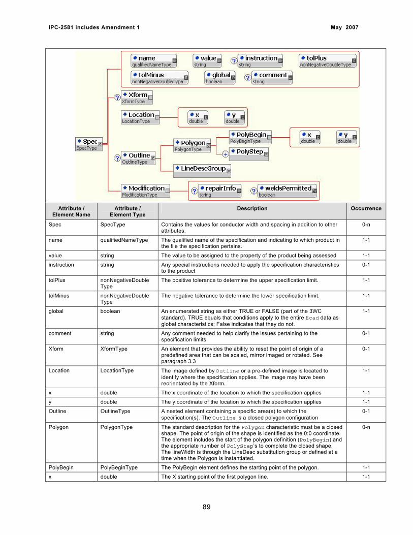
IPC-2581 includes Amendment 1 May 2007
Attribute / Element Name
Attribute / Element Type
Description Occurrence
Spec SpecType Contains the values for conductor width and spacing in addition to other attributes.
0-n
name qualifiedNameType The qualified name of the specification and indicating to which product in the file the specification pertains.
1-1
value string The value to be assigned to the property of the product being assessed 1-1
instruction string Any special instructions needed to apply the specification characteristics to the product
0-1
tolPlus nonNegativeDouble Type
The positive tolerance to determine the upper specification limit. 1-1
tolMinus nonNegativeDouble Type
The negative tolerance to determine the lower specification limit. 1-1
global boolean An enumerated string as either TRUE or FALSE (part of the 3WC standard). TRUE equals that conditions apply to the entire Ecad data as global characteristics; False indicates that they do not.
1-1
comment string Any comment needed to help clarify the issues pertaining to the specification limits.
0-1
Xform XformType An element that provides the ability to reset the point of origin of a predefined area that can be scaled, mirror imaged or rotated. See paragraph 3.3
0-1
Location LocationType The image defined by Outline or a pre-defined image is located to identify where the specification applies. The image may have been reorientated by the Xform.
1-1
x double The x coordinate of the location to which the specification applies 1-1
y double The y coordinate of the location to which the specification applies 1-1
Outline OutlineType A nested element containing a specific area(s) to which the specification(s). The Outline is a closed polygon configuration
0-1
Polygon PolygonType The standard description for the Polygon characteristic must be a closed shape. The point of origin of the shape is identified as the 0:0 coordinate. The element includes the start of the polygon definition (PolyBegin) and the appropriate number of PolyStep’s to complete the closed shape. The lineWidth is through the LineDesc substitution group or defined at a time when the Polygon is instantiated.
0-n
PolyBegin PolyBeginType The PolyBegin element defines the starting point of the polygon. 1-1
x double The X starting point of the first polygon line. 1-1
89
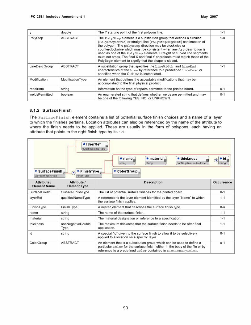
IPC-2581 includes Amendment 1 May 2007
y double The Y starting point of the first polygon line. 1-1
PolyStep ABSTRACT The PolyStep element is a substitution group that defines a circular (PolyStepCurve) or straight line (PolyStepSegment) continuation of the polygon. The polystep direction may be clockwise or counterclockwise which must be consistent when any Arc description is used as one of the PolyStep elements. Straight or curved line segments must not cross. The final X and final Y coordinate must match those of the PolyBegin element to signify that the shape is closed.
1-n
LineDescGroup ABSTRACT A substitution group that specifies the LineWidth and LineEnd characteristics of the Line by reference to a predefined LineDesc or specified when the Outline is instantiated.
1-1
Modification ModificationType An element that defines the acceptable modifications that may be accomplished to the final physical product.
repairInfo string Information on the type of repairs permitted to the printed board. 0-1
weldsPermitted boolean An enumerated string that defines whether welds are permitted and may be one of the following YES; NO; or UNKNOWN.
0-1
8.1.2 SurfaceFinish The SurfaceFinish element contains a list of potential surface finish choices and a name of a layer to which the finishes pertains. Location attributes can also be referenced by the name of the attribute to where the finish needs to be applied. These are usually in the form of polygons, each having an attribute that points to the right finish type by its id.
Attribute / Element Name
Attribute / Element Type
Description Occurrence
SurfaceFinish SurfaceFinishType The list of potential surface finishes for the printed board. 0-1
layerRef qualifiedNameType A reference to the layer element identified by the layer “Name” to which the surface finish applies.
1-1
FinishType FinishType A nested element that describes the surface finish type. 0-n
name string The name of the surface finish. 1-1
material string The material designation or reference to a specification. 1-1
thickness nonNegativeDouble Type
The maximum thickness that the surface finish needs to be after final application.
1-1
id string A special “id” given to the surface finish to allow it to be selectively applied to a location on a specific layer.
0-1
ColorGroup ABSTRACT An element that is a substitution group which can be used to define a particular Color for the surface finish, either in the body of the file or by reference to a predefined Color contained in DictionaryColor.
0-1
90
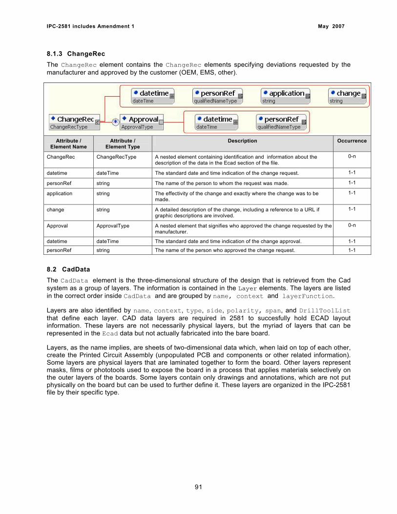
IPC-2581 includes Amendment 1 May 2007
8.1.3 ChangeRec The ChangeRec element contains the ChangeRec elements specifying deviations requested by the manufacturer and approved by the customer (OEM, EMS, other).
Attribute / Element Name
Attribute / Element Type
Description Occurrence
ChangeRec ChangeRecType A nested element containing identification and information about the description of the data in the Ecad section of the file.
0-n
datetime dateTime The standard date and time indication of the change request. 1-1
personRef string The name of the person to whom the request was made. 1-1
application string The effectivity of the change and exactly where the change was to be made.
1-1
change string A detailed description of the change, including a reference to a URL if graphic descriptions are involved.
1-1
Approval ApprovalType A nested element that signifies who approved the change requested by the manufacturer.
0-n
datetime dateTime The standard date and time indication of the change approval. 1-1
personRef string The name of the person who approved the change request. 1-1
8.2 CadData The CadData element is the three-dimensional structure of the design that is retrieved from the Cad system as a group of layers. The information is contained in the Layer elements. The layers are listed in the correct order inside CadData and are grouped by name, context and layerFunction.
Layers are also identified by name, context, type, side, polarity, span, and DrillToolList that define each layer. CAD data layers are required in 2581 to succesfully hold ECAD layout information. These layers are not necessarily physical layers, but the myriad of layers that can be represented in the Ecad data but not actually fabricated into the bare board.
Layers, as the name implies, are sheets of two-dimensional data which, when laid on top of each other, create the Printed Circuit Assembly (unpopulated PCB and components or other related information). Some layers are physical layers that are laminated together to form the board. Other layers represent masks, films or phototools used to expose the board in a process that applies materials selectively on the outer layers of the boards. Some layers contain only drawings and annotations, which are not put physically on the board but can be used to further define it. These layers are organized in the IPC-2581 file by their specific type.
91
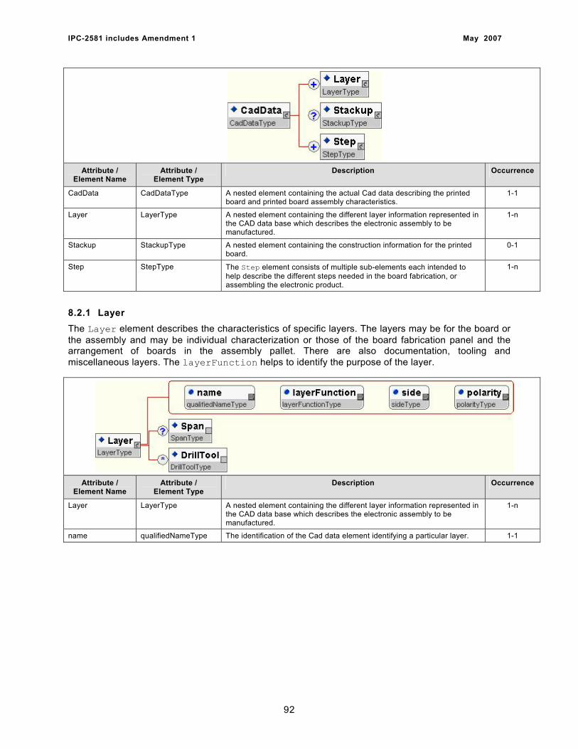
IPC-2581 includes Amendment 1 May 2007
Attribute / Element Name
Attribute / Element Type
Description Occurrence
CadData CadDataType A nested element containing the actual Cad data describing the printed board and printed board assembly characteristics.
1-1
Layer LayerType A nested element containing the different layer information represented in the CAD data base which describes the electronic assembly to be manufactured.
1-n
Stackup StackupType A nested element containing the construction information for the printed board.
0-1
Step StepType The Step element consists of multiple sub-elements each intended to help describe the different steps needed in the board fabrication, or assembling the electronic product.
1-n
8.2.1 Layer The Layer element describes the characteristics of specific layers. The layers may be for the board or the assembly and may be individual characterization or those of the board fabrication panel and the arrangement of boards in the assembly pallet. There are also documentation, tooling and miscellaneous layers. The layerFunction helps to identify the purpose of the layer.
Attribute / Element Name
Attribute / Element Type
Description Occurrence
Layer LayerType A nested element containing the different layer information represented in the CAD data base which describes the electronic assembly to be manufactured.
1-n
name qualifiedNameType The identification of the Cad data element identifying a particular layer. 1-1
92
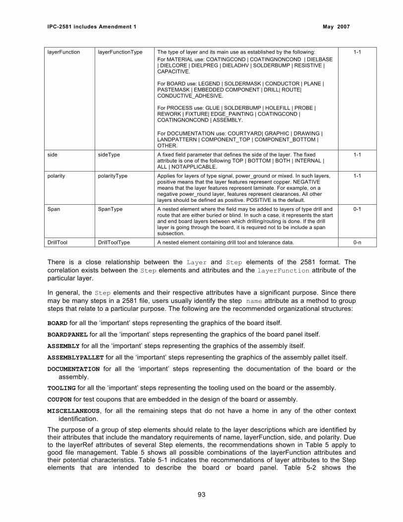
IPC-2581 includes Amendment 1 May 2007
layerFunction layerFunctionType The type of layer and its main use as established by the following: For MATERIAL use: COATINGCOND | COATINGNONCOND | DIELBASE | DIELCORE | DIELPREG | DIELADHV | SOLDERBUMP | RESISTIVE | CAPACITIVE. For BOARD use: LEGEND | SOLDERMASK | CONDUCTOR | PLANE | PASTEMASK | EMBEDDED COMPONENT | DRILL| ROUTE| CONDUCTIVE_ADHESIVE. For PROCESS use: GLUE | SOLDERBUMP | HOLEFILL | PROBE | REWORK | FIXTURE| EDGE_PAINTING | COATINGCOND | COATINGNONCOND | ASSEMBLY. For DOCUMENTATION use: COURTYARD| GRAPHIC | DRAWING | LANDPATTERN | COMPONENT_TOP | COMPONENT_BOTTOM | OTHER.
1-1
side sideType A fixed field parameter that defines the side of the layer. The fixed attribute is one of the following TOP | BOTTOM | BOTH | INTERNAL | ALL | NOTAPPLICABLE.
1-1
polarity polarityType Applies for layers of type signal, power_ground or mixed. In such layers, positive means that the layer features represent copper. NEGATIVE means that the layer features represent laminate. For example, on a negative power_round layer, features represent clearances. All other layers should be defined as positive. POSITIVE is the default.
1-1
Span SpanType A nested element where the field may be added to layers of type drill and route that are either buried or blind. In such a case, it represents the start and end board layers between which drilling/routing is done. If the drill layer is going through the board, it is required not to be include a span subsection.
0-1
DrillTool DrillToolType A nested element containing drill tool and tolerance data. 0-n
There is a close relationship between the Layer and Step elements of the 2581 format. The correlation exists between the Step elements and attributes and the layerFunction attribute of the particular layer.
In general, the Step elements and their respective attributes have a significant purpose. Since there may be many steps in a 2581 file, users usually identify the step name attribute as a method to group steps that relate to a particular purpose. The following are the recommended organizational structures:
BOARD for all the ‘important’ steps representing the graphics of the board itself.
BOARDPANEL for all the ‘important’ steps representing the graphics of the board panel itself.
ASSEMBLY for all the ‘important’ steps representing the graphics of the assembly itself.
ASSEMBLYPALLET for all the ‘important’ steps representing the graphics of the assembly pallet itself.
DOCUMENTATION for all the ‘important’ steps representing the documentation of the board or the assembly.
TOOLING for all the ‘important’ steps representing the tooling used on the board or the assembly.
COUPON for test coupons that are embedded in the design of the board or assembly.
MISCELLANEOUS, for all the remaining steps that do not have a home in any of the other context identification.
The purpose of a group of step elements should relate to the layer descriptions which are identified by their attributes that include the mandatory requirements of name, layerFunction, side, and polarity. Due to the layerRef attributes of several Step elements, the recommendations shown in Table 5 apply to good file management. Table 5 shows all possible combinations of the layerFunction attributes and their potential characteristics. Table 5-1 indicates the recommendations of layer attributes to the Step elements that are intended to describe the board or board panel. Table 5-2 shows the
93
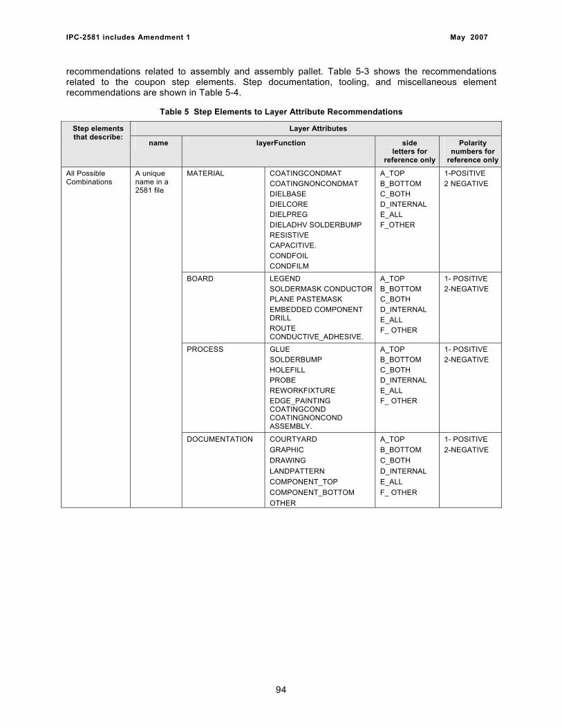
IPC-2581 includes Amendment 1 May 2007
recommendations related to assembly and assembly pallet. Table 5-3 shows the recommendations related to the coupon step elements. Step documentation, tooling, and miscellaneous element recommendations are shown in Table 5-4.
Table 5 Step Elements to Layer Attribute Recommendations
Layer Attributes Step elements that describe:
name layerFunction side letters for
reference only
Polarity numbers for
reference only
MATERIAL COATINGCONDMAT COATINGNONCONDMAT DIELBASE DIELCORE DIELPREG DIELADHV SOLDERBUMP RESISTIVE CAPACITIVE. CONDFOIL CONDFILM
A_TOP B_BOTTOM C_BOTH D_INTERNAL E_ALL F_OTHER
1-POSITIVE 2 NEGATIVE
BOARD LEGEND SOLDERMASK CONDUCTORPLANE PASTEMASK EMBEDDED COMPONENT DRILL ROUTE CONDUCTIVE_ADHESIVE.
A_TOP B_BOTTOM C_BOTH D_INTERNAL E_ALL F_ OTHER
1- POSITIVE 2-NEGATIVE
PROCESS GLUE SOLDERBUMP HOLEFILL PROBE REWORKFIXTURE EDGE_PAINTING COATINGCOND COATINGNONCOND ASSEMBLY.
A_TOP B_BOTTOM C_BOTH D_INTERNAL E_ALL F_ OTHER
1- POSITIVE 2-NEGATIVE
All Possible Combinations
A unique name in a 2581 file
DOCUMENTATION COURTYARD GRAPHIC DRAWING LANDPATTERN COMPONENT_TOP COMPONENT_BOTTOM OTHER
A_TOP B_BOTTOM C_BOTH D_INTERNAL E_ALL F_ OTHER
1- POSITIVE 2-NEGATIVE
94

IPC-2581 includes Amendment 1 May 2007
Table 5-1 Step Elements to Layer Attribute Recommendations for Board or Board Panel
Layer Attributes Step elements that describe:
name layerFunction side letters for
reference only
Polarity numbers for
reference only
COATINGCONDMAT A|B|C|D|E 1
COATINGNONCONDMAT A|B|C|D|E 1|2
DIELBASE
MATERIAL
A|B|C|D 1|2
DIELCORE A|B|C|D 1|2
DIELPREG D 1|2
DIELADHV A|B|C|D 1
SOLDERBUMP A|B|C|D 1|2
RESISTIVE D 1|2
CAPACITIVE D 1|2
CONDFOIL A|B|C|D|E 1|2
CONDFILM A|B|C|D|E 1|2
LEGEND. A|B|C|D 1|2
SOLDERMASK A|B|C|
BOARD
1|2
CONDUCTOR A|B|C|D 1|2
PLANE A|B|C|D 1|2
PASTEMASK A|B|C 1|2
EMBEDDED COMPONENT D 1
DRILL A|B|C|D|E 1
ROUTE A|B|C|D|E 1|2
CONDUCTIVE_ADHESIVE A|B|C|D 1
GLUE A|B 1 PROCESS
SOLDERBUMP A|B 1
HOLEFILL A|B|C 1
PROBE A|B|C 1
REWORKFIXTURE F 1
EDGE_PAINTING F 1
COATINGCOND A|B|C|D|E 1
COATINGNONCOND A|B|C|D|E 1|2
ASSEMBLY. F 1
COURTYARD F 1
GRAPHIC A|B|C|D|E 1|2
DRAWING A|B|C|D|E 1
LANDPATTERN A|B|C|D|E 1
COMPONENT_TOP A 1
COMPONENT_BOTTOM B 1
BOARD AND BOARD PANEL
A unique name in a 2581 file
DOCUMENTATION
OTHER A|B|C|D|E 1
95
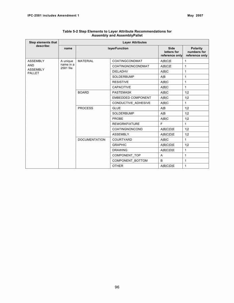
IPC-2581 includes Amendment 1 May 2007
Table 5-2 Step Elements to Layer Attribute Recommendations for Assembly and AssemblyPallet
Layer Attributes Step elements that describe:
name layerFunction Side letters for
reference only
Polarity numbers for
reference only
COATINGCONDMAT A|B|C|E 1
COATINGNONCONDMAT A|B|C|E 1
DIELADHV A|B|C 1
SOLDERBUMP A|B 1
RESISTIVE A|B|C 1
MATERIAL
CAPACITIVE A|B|C 1
PASTEMASK A|B|C 1|2
EMBEDDED COMPONENT A|B|C 1|2
BOARD
CONDUCTIVE_ADHESIVE A|B|C 1
GLUE A|B 1|2
SOLDERBUMP A|B 1|2
PROBE A|B|C 1|2
REWORKFIXTURE F 1
COATINGNONCOND A|B|C|D|E 1|2
PROCESS
ASSEMBLY. A|B|C|D|E 1|2
COURTYARD A|B|C 1
GRAPHIC A|B|C|D|E 1|2
DRAWING A|B|C|D|E 1
COMPONENT_TOP A 1
COMPONENT_BOTTOM B 1
ASSEMBLY AND ASSEMBLY PALLET
A unique name in a 2581 file
DOCUMENTATION
OTHER A|B|C|D|E 1
96
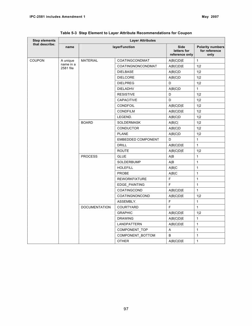
IPC-2581 includes Amendment 1 May 2007
Table 5-3 Step Element to Layer Attribute Recommendations for Coupon
Layer Attributes Step elements that describe:
name layerFunction Side letters for
reference only
Polarity numbers for reference
only
COATINGCONDMAT A|B|C|D|E 1
COATINGNONCONDMAT A|B|C|D|E 1|2
DIELBASE A|B|C|D 1|2
DIELCORE A|B|C|D 1|2
DIELPREG D 1|2
DIELADHV A|B|C|D 1
RESISTIVE D 1|2
CAPACITIVE D 1|2
CONDFOIL A|B|C|D|E 1|2
CONDFILM A|B|C|D|E 1|2
MATERIAL
LEGEND. A|B|C|D 1|2
SOLDERMASK A|B|C| 1|2
CONDUCTOR A|B|C|D 1|2
PLANE A|B|C|D 1|2
EMBEDDED COMPONENT D 1
DRILL A|B|C|D|E 1
BOARD
ROUTE A|B|C|D|E 1|2
GLUE A|B 1
SOLDERBUMP A|B 1
HOLEFILL A|B|C 1
PROBE A|B|C 1
REWORKFIXTURE F 1
EDGE_PAINTING F 1
COATINGCOND A|B|C|D|E 1
COATINGNONCOND A|B|C|D|E 1|2
PROCESS
ASSEMBLY. F 1
COURTYARD F 1
GRAPHIC A|B|C|D|E 1|2
DRAWING A|B|C|D|E 1
LANDPATTERN A|B|C|D|E 1
COMPONENT_TOP A 1
COMPONENT_BOTTOM B 1
COUPON A unique name in a 2581 file
DOCUMENTATION
OTHER A|B|C|D|E 1
97
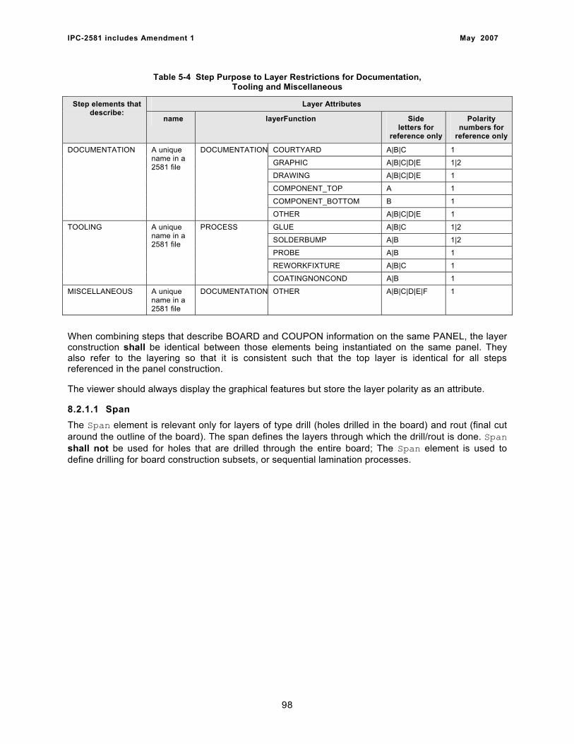
IPC-2581 includes Amendment 1 May 2007
Table 5-4 Step Purpose to Layer Restrictions for Documentation, Tooling and Miscellaneous
Layer Attributes Step elements that describe:
name layerFunction Side letters for
reference only
Polarity numbers for
reference only
COURTYARD A|B|C 1
GRAPHIC A|B|C|D|E 1|2
DRAWING A|B|C|D|E 1
COMPONENT_TOP A 1
COMPONENT_BOTTOM B 1
DOCUMENTATION A unique name in a 2581 file
DOCUMENTATION
OTHER A|B|C|D|E 1
GLUE A|B|C 1|2
SOLDERBUMP A|B 1|2
PROBE A|B 1
REWORKFIXTURE A|B|C 1
TOOLING A unique name in a 2581 file
PROCESS
COATINGNONCOND A|B 1
MISCELLANEOUS A unique name in a 2581 file
DOCUMENTATION OTHER A|B|C|D|E|F 1
When combining steps that describe BOARD and COUPON information on the same PANEL, the layer construction shall be identical between those elements being instantiated on the same panel. They also refer to the layering so that it is consistent such that the top layer is identical for all steps referenced in the panel construction.
The viewer should always display the graphical features but store the layer polarity as an attribute.
8.2.1.1 Span The Span element is relevant only for layers of type drill (holes drilled in the board) and rout (final cut around the outline of the board). The span defines the layers through which the drill/rout is done. Span shall not be used for holes that are drilled through the entire board; The Span element is used to define drilling for board construction subsets, or sequential lamination processes.
98
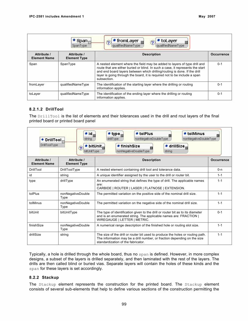
IPC-2581 includes Amendment 1 May 2007
Attribute / Element Name
Attribute / Element Type
Description Occurrence
Span SpanType A nested element where the field may be added to layers of type drill and route that are either buried or blind. In such a case, it represents the start and end board layers between which drilling/routing is done. If the drill layer is going through the board, it is required not to be include a span subsection.
0-1
fromLayer qualifiedNameType The identification of the starting layer where the drilling or routing information applies.
0-1
toLayer qualifiedNameType The identification of the ending layer where the drilling or routing information applies.
0-1
8.2.1.2 DrillTool The DrillTool is the list of elements and their tolerances used in the drill and rout layers of the final printed board or printed board panel
Attribute / Element Name
Attribute / Element Type
Description Occurrence
DrillTool DrillToolType A nested element containing drill tool and tolerance data. 0-n
id string A unique identifier assigned by the user to the drill or router bit. 1-1
type drillType An enumerated string that defines the type of drill. The applicable names are: CARBIDE | ROUTER | LASER | FLATNOSE | EXTENSION.
1-1
tolPlus nonNegativeDouble Type
The permitted variation on the positive side of the nominal drill size. 1-1
tolMinus nonNegativeDouble Type
The permitted variation on the negative side of the nominal drill size. 1-1
bitUnit bitUnitType The type of identification given to the drill or router bit as to its diameter and is an enumerated string. The applicable names are: FRACTION | WIREGAUGE | LETTER | METRIC.
0-1
finishSize nonNegativeDouble Type
A numerical range description of the finished hole or routing slot size. 1-1
drillSize string The size of the drill or router bit used to produce the holes or routing path. The information may be a drill number, or fraction depending on the size standardization of the fabricator.
1-1
Typically, a hole is drilled through the whole board, thus no span is defined. However, in more complex designs, a subset of the layers is drilled separately, and then laminated with the rest of the layers. The drills are then called blind or buried vias. Separate layers will contain the holes of these kinds and the span for these layers is set accordingly.
8.2.2 Stackup The Stackup element represents the construction for the printed board. The Stackup element consists of several sub-elements that help to define various sections of the construction permitting the
99
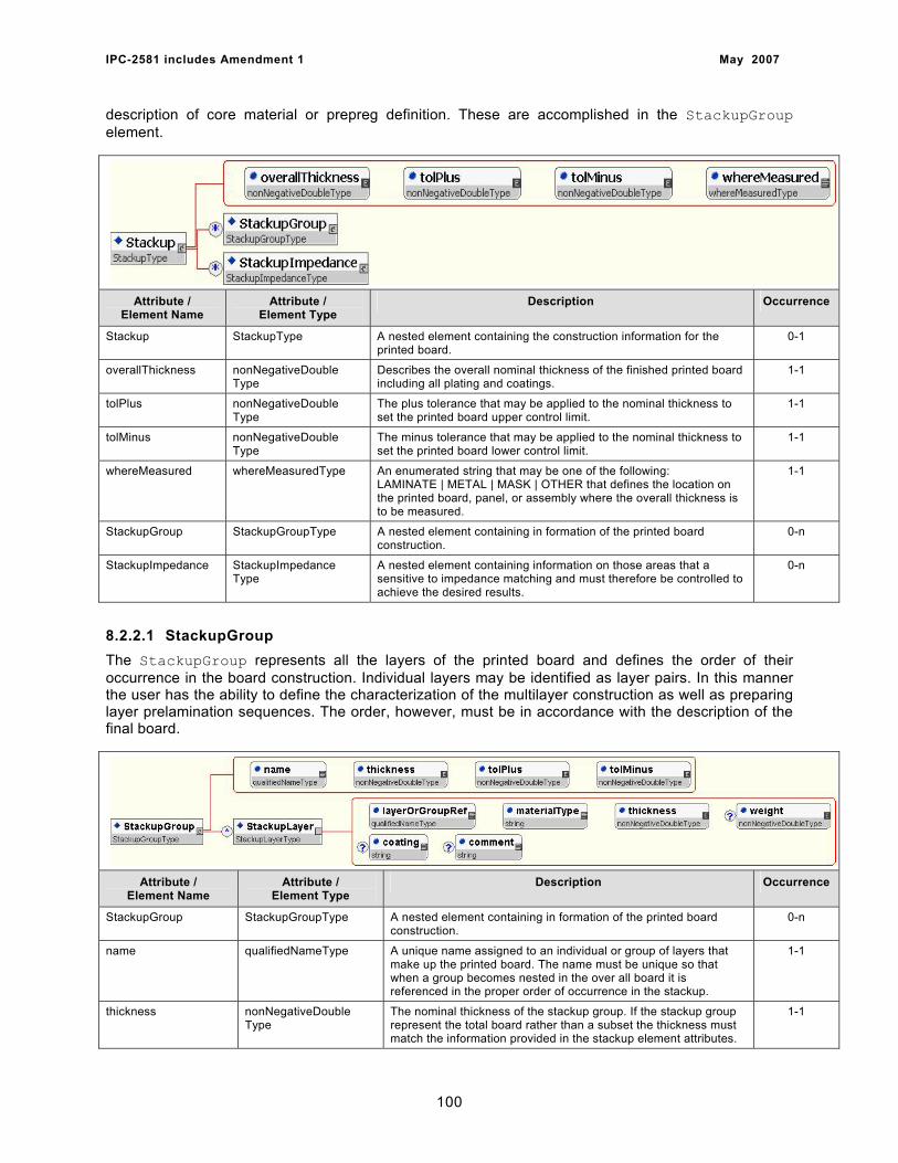
IPC-2581 includes Amendment 1 May 2007
description of core material or prepreg definition. These are accomplished in the StackupGroup element.
Attribute / Element Name
Attribute / Element Type
Description Occurrence
Stackup StackupType A nested element containing the construction information for the printed board.
0-1
overallThickness nonNegativeDouble Type
Describes the overall nominal thickness of the finished printed board including all plating and coatings.
1-1
tolPlus nonNegativeDouble Type
The plus tolerance that may be applied to the nominal thickness to set the printed board upper control limit.
1-1
tolMinus nonNegativeDouble Type
The minus tolerance that may be applied to the nominal thickness to set the printed board lower control limit.
1-1
whereMeasured whereMeasuredType An enumerated string that may be one of the following: LAMINATE | METAL | MASK | OTHER that defines the location on the printed board, panel, or assembly where the overall thickness is to be measured.
1-1
StackupGroup StackupGroupType A nested element containing in formation of the printed board construction.
0-n
StackupImpedance StackupImpedance Type
A nested element containing information on those areas that a sensitive to impedance matching and must therefore be controlled to achieve the desired results.
0-n
8.2.2.1 StackupGroup The StackupGroup represents all the layers of the printed board and defines the order of their occurrence in the board construction. Individual layers may be identified as layer pairs. In this manner the user has the ability to define the characterization of the multilayer construction as well as preparing layer prelamination sequences. The order, however, must be in accordance with the description of the final board.
Attribute / Element Name
Attribute / Element Type
Description Occurrence
StackupGroup StackupGroupType A nested element containing in formation of the printed board construction.
0-n
name qualifiedNameType A unique name assigned to an individual or group of layers that make up the printed board. The name must be unique so that when a group becomes nested in the over all board it is referenced in the proper order of occurrence in the stackup.
1-1
thickness nonNegativeDouble Type
The nominal thickness of the stackup group. If the stackup group represent the total board rather than a subset the thickness must match the information provided in the stackup element attributes.
1-1
100
IPC-2581 includes Amendment 1 May 2007
tolPlus nonNegativeDouble Type
The plus tolerance that may be applied to the nominal thickness to set the stackupGroup upper control limit.
1-1
tolMinus nonNegativeDouble Type
The minus tolerance that may be applied to the nominal thickness to set the stackupGroup lower control limit.
1-1
StackupLayer StackupLayerType A nested element containing in all the layer formation as to how the printed board is constructed. If layer pairs are produced separately possibly containing buried vias they are defined as a separate group and then positioned in the appropriate order of their occurrence in the stackup.
0-n
LayerOrGroupRef qualifiedNameType A reference to an individual layer or a group that has been previously identified. A single sheet of copper foil may be a named layer and would thus apply to the group, as would a layer pair of copper clad laminate purchased from a laminator.
1-1
materialType string Identification of the material in the stackup. The material may be conductive or nonconductive, film, adhesive, prepreg, copper foil or metal core.
1-1
thickness nonNegativeDouble Type
The thickness of the particular material being defined. The thickness matches nominal thickness of a predefined StackupGroup.
1-1
weight nonNegativeDouble Type
An optional attribute mostly used to define starting copper foil or metal cores which are measured in ounces.
0-1
coating string An optional attribute used to define special coating used in the stackup, such as adhesives, solder mask or selective conformal coating.
0-1
comment string An optional attribute used to provide any special instructions about the layering or stackup of a multilayer single-sided, or double-sided printed board.
0-1
8.2.2.2 StackupImpedance The StackupImpedance element defines the circuits that have impedance control requirements. The elements and descriptions define those circuits contained in the design that must meet the requirements of impedance control. These characteristics are a function of the design intent and may not necessarily reflect the final characteristics of the conductor topology or stackup hierarchy identified in Layers and/or Step. The information reflects the original file creation and may be used to verify that the HistoryRecord is intact.
Since the details of the XML description reflects the design requirements the information may only be changed by the file owner.
101
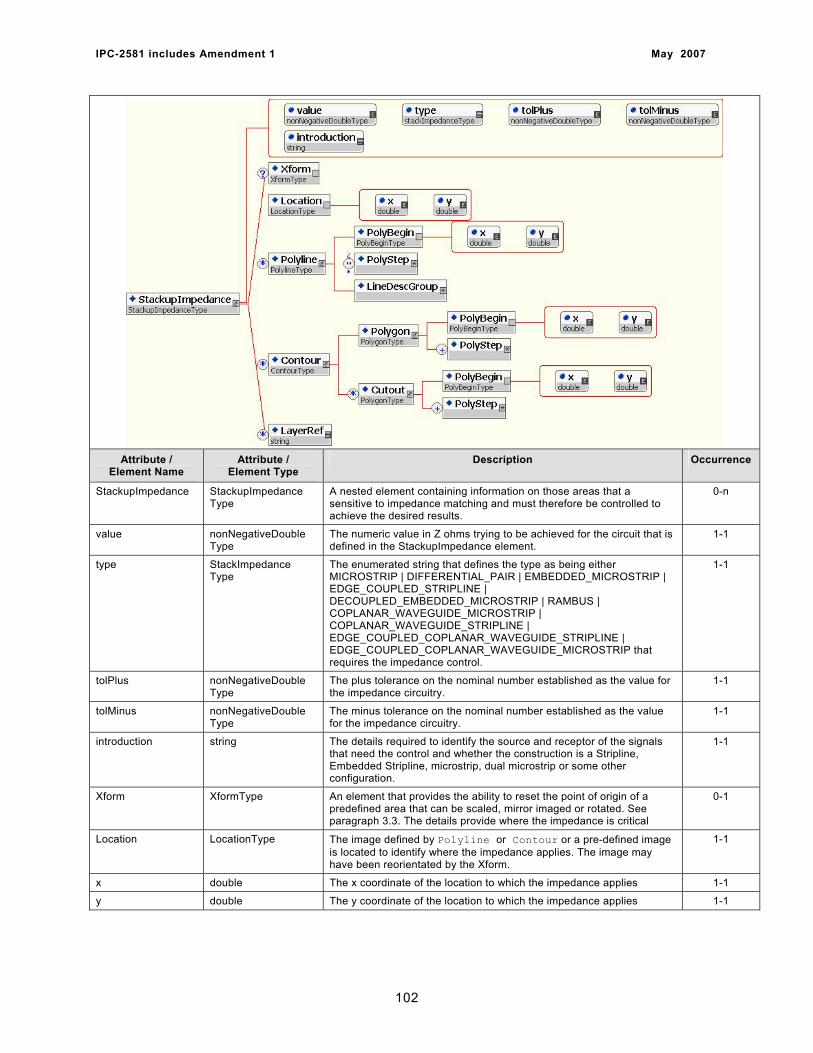
IPC-2581 includes Amendment 1 May 2007
Attribute /
Element Name Attribute /
Element Type Description Occurrence
StackupImpedance StackupImpedance Type
A nested element containing information on those areas that a sensitive to impedance matching and must therefore be controlled to achieve the desired results.
0-n
value nonNegativeDouble Type
The numeric value in Z ohms trying to be achieved for the circuit that is defined in the StackupImpedance element.
1-1
type StackImpedance Type
The enumerated string that defines the type as being either MICROSTRIP | DIFFERENTIAL_PAIR | EMBEDDED_MICROSTRIP | EDGE_COUPLED_STRIPLINE | DECOUPLED_EMBEDDED_MICROSTRIP | RAMBUS | COPLANAR_WAVEGUIDE_MICROSTRIP | COPLANAR_WAVEGUIDE_STRIPLINE | EDGE_COUPLED_COPLANAR_WAVEGUIDE_STRIPLINE | EDGE_COUPLED_COPLANAR_WAVEGUIDE_MICROSTRIP that requires the impedance control.
1-1
tolPlus nonNegativeDouble Type
The plus tolerance on the nominal number established as the value for the impedance circuitry.
1-1
tolMinus nonNegativeDouble Type
The minus tolerance on the nominal number established as the value for the impedance circuitry.
1-1
introduction string The details required to identify the source and receptor of the signals that need the control and whether the construction is a Stripline, Embedded Stripline, microstrip, dual microstrip or some other configuration.
1-1
Xform XformType An element that provides the ability to reset the point of origin of a predefined area that can be scaled, mirror imaged or rotated. See paragraph 3.3. The details provide where the impedance is critical
0-1
Location LocationType The image defined by Polyline or Contour or a pre-defined image is located to identify where the impedance applies. The image may have been reorientated by the Xform.
1-1
x double The x coordinate of the location to which the impedance applies 1-1
y double The y coordinate of the location to which the impedance applies 1-1
102
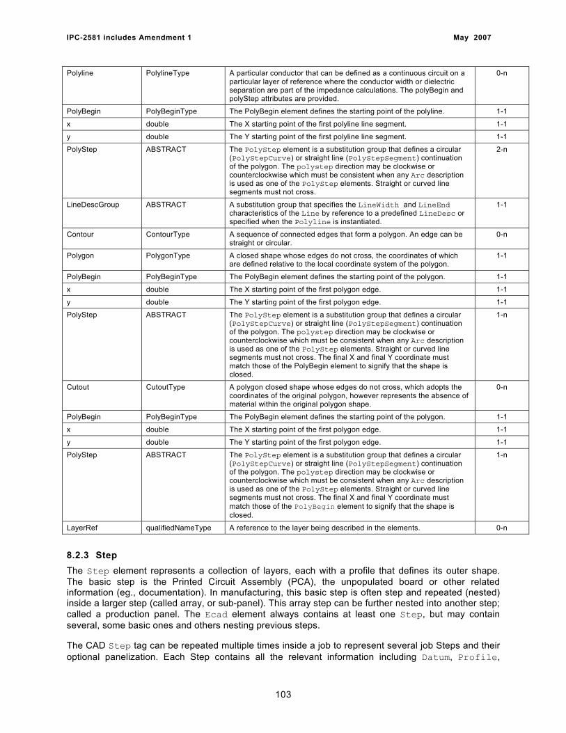
IPC-2581 includes Amendment 1 May 2007
Polyline PolylineType A particular conductor that can be defined as a continuous circuit on a particular layer of reference where the conductor width or dielectric separation are part of the impedance calculations. The polyBegin and polyStep attributes are provided.
0-n
PolyBegin PolyBeginType The PolyBegin element defines the starting point of the polyline. 1-1
x double The X starting point of the first polyline line segment. 1-1
y double The Y starting point of the first polyline line segment. 1-1
PolyStep ABSTRACT The PolyStep element is a substitution group that defines a circular (PolyStepCurve) or straight line (PolyStepSegment) continuation of the polygon. The polystep direction may be clockwise or counterclockwise which must be consistent when any Arc description is used as one of the PolyStep elements. Straight or curved line segments must not cross.
2-n
LineDescGroup ABSTRACT A substitution group that specifies the LineWidth and LineEnd characteristics of the Line by reference to a predefined LineDesc or specified when the Polyline is instantiated.
1-1
Contour ContourType A sequence of connected edges that form a polygon. An edge can be straight or circular.
0-n
Polygon PolygonType A closed shape whose edges do not cross, the coordinates of which are defined relative to the local coordinate system of the polygon.
1-1
PolyBegin PolyBeginType The PolyBegin element defines the starting point of the polygon. 1-1
x double The X starting point of the first polygon edge. 1-1
y double The Y starting point of the first polygon edge. 1-1
PolyStep ABSTRACT The PolyStep element is a substitution group that defines a circular (PolyStepCurve) or straight line (PolyStepSegment) continuation of the polygon. The polystep direction may be clockwise or counterclockwise which must be consistent when any Arc description is used as one of the PolyStep elements. Straight or curved line segments must not cross. The final X and final Y coordinate must match those of the PolyBegin element to signify that the shape is closed.
1-n
Cutout CutoutType A polygon closed shape whose edges do not cross, which adopts the coordinates of the original polygon, however represents the absence of material within the original polygon shape.
0-n
PolyBegin PolyBeginType The PolyBegin element defines the starting point of the polygon. 1-1
x double The X starting point of the first polygon edge. 1-1
y double The Y starting point of the first polygon edge. 1-1
PolyStep ABSTRACT The PolyStep element is a substitution group that defines a circular (PolyStepCurve) or straight line (PolyStepSegment) continuation of the polygon. The polystep direction may be clockwise or counterclockwise which must be consistent when any Arc description is used as one of the PolyStep elements. Straight or curved line segments must not cross. The final X and final Y coordinate must match those of the PolyBegin element to signify that the shape is closed.
1-n
LayerRef qualifiedNameType A reference to the layer being described in the elements. 0-n
8.2.3 Step The Step element represents a collection of layers, each with a profile that defines its outer shape. The basic step is the Printed Circuit Assembly (PCA), the unpopulated board or other related information (eg., documentation). In manufacturing, this basic step is often step and repeated (nested) inside a larger step (called array, or sub-panel). This array step can be further nested into another step; called a production panel. The Ecad element always contains at least one Step, but may contain several, some basic ones and others nesting previous steps.
The CAD Step tag can be repeated multiple times inside a job to represent several job Steps and their optional panelization. Each Step contains all the relevant information including Datum, Profile,
103
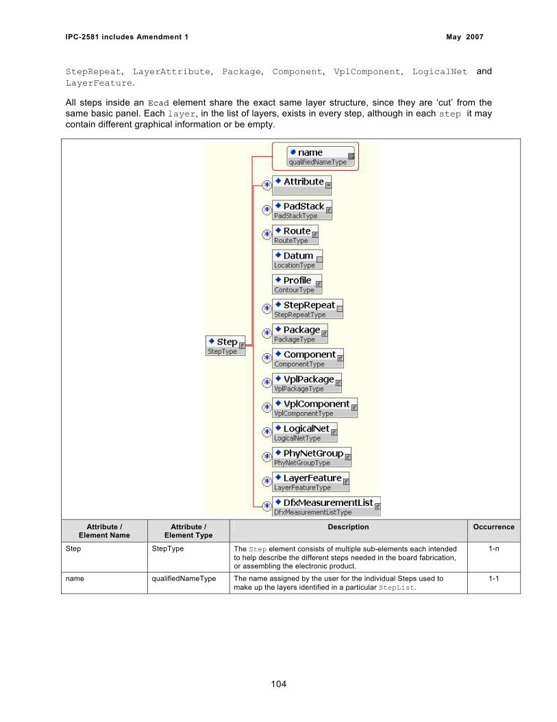
IPC-2581 includes Amendment 1 May 2007
StepRepeat, LayerAttribute, Package, Component, VplComponent, LogicalNet and LayerFeature.
All steps inside an Ecad element share the exact same layer structure, since they are ‘cut’ from the same basic panel. Each layer, in the list of layers, exists in every step, although in each step it may contain different graphical information or be empty.
Attribute / Element Name
Attribute / Element Type
Description Occurrence
Step StepType The Step element consists of multiple sub-elements each intended to help describe the different steps needed in the board fabrication, or assembling the electronic product.
1-n
name qualifiedNameType The name assigned by the user for the individual Steps used to make up the layers identified in a particular StepList.
1-1
104
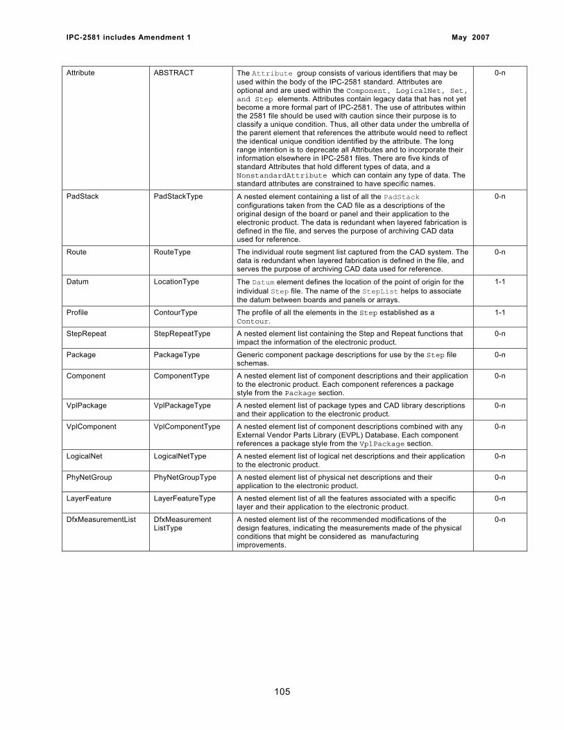
IPC-2581 includes Amendment 1 May 2007
Attribute ABSTRACT The Attribute group consists of various identifiers that may be used within the body of the IPC-2581 standard. Attributes are optional and are used within the Component, LogicalNet, Set, and Step elements. Attributes contain legacy data that has not yet become a more formal part of IPC-2581. The use of attributes within the 2581 file should be used with caution since their purpose is to classify a unique condition. Thus, all other data under the umbrella of the parent element that references the attribute would need to reflect the identical unique condition identified by the attribute. The long range intention is to deprecate all Attributes and to incorporate their information elsewhere in IPC-2581 files. There are five kinds of standard Attributes that hold different types of data, and a NonstandardAttribute which can contain any type of data. The standard attributes are constrained to have specific names.
0-n
PadStack PadStackType A nested element containing a list of all the PadStack configurations taken from the CAD file as a descriptions of the original design of the board or panel and their application to the electronic product. The data is redundant when layered fabrication is defined in the file, and serves the purpose of archiving CAD data used for reference.
0-n
Route RouteType The individual route segment list captured from the CAD system. The data is redundant when layered fabrication is defined in the file, and serves the purpose of archiving CAD data used for reference.
0-n
Datum LocationType The Datum element defines the location of the point of origin for the individual Step file. The name of the StepList helps to associate the datum between boards and panels or arrays.
1-1
Profile ContourType The profile of all the elements in the Step established as a Contour.
1-1
StepRepeat StepRepeatType A nested element list containing the Step and Repeat functions that impact the information of the electronic product.
0-n
Package PackageType Generic component package descriptions for use by the Step file schemas.
0-n
Component ComponentType A nested element list of component descriptions and their application to the electronic product. Each component references a package style from the Package section.
0-n
VplPackage VplPackageType A nested element list of package types and CAD library descriptions and their application to the electronic product.
0-n
VplComponent VplComponentType A nested element list of component descriptions combined with any External Vendor Parts Library (EVPL) Database. Each component references a package style from the VplPackage section.
0-n
LogicalNet LogicalNetType A nested element list of logical net descriptions and their application to the electronic product.
0-n
PhyNetGroup PhyNetGroupType A nested element list of physical net descriptions and their application to the electronic product.
0-n
LayerFeature LayerFeatureType A nested element list of all the features associated with a specific layer and their application to the electronic product.
0-n
DfxMeasurementList DfxMeasurement ListType
A nested element list of the recommended modifications of the design features, indicating the measurements made of the physical conditions that might be considered as manufacturing improvements.
0-n
105
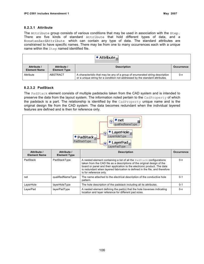
IPC-2581 includes Amendment 1 May 2007
8.2.3.1 Attribute The Attribute group consists of various conditions that may be used in association with the Step. There are five kinds of standard Attribute that hold different types of data, and a NonstandardAttribute which can contain any type of data. The standard attributes are constrained to have specific names. There may be from one to many occurrences each with a unique name within the Step named identified file.
Attribute / Element Name
Attribute / Element Type
Description Occurrence
Attribute ABSTRACT A characteristic that may be any of a group of enumerated string description or a unique string for a condition not addressed by the standard attributes.
0-n
8.2.3.2 PadStack The PadStack element consists of multiple padstacks taken from the CAD system and is intended to preserve the data from the layout system. The information noted pertain to the CadProperty of which the padstack is a part. The relationship is identified by the CadProperty unique name and is the original design file from the CAD system. The data becomes redundant when the individual layered features are defined and is then for reference only.
Attribute / Element Name
Attribute / Element Type
Description Occurrence
PadStack PadStackType A nested element containing a list of all the PadStack configurations taken from the CAD file as a descriptions of the original design of the board or panel and their application to the electronic product. The data is redundant when layered fabrication is defined in the file, and therefore is for reference only.
0-n
net qualifiedNameType The name attached to the electrical description of the conductive hole pattern.
0-1
LayerHole layerHoleType The hole description of the padstack including all its attributes. 0-1
LayerPad layerPadType A nested element defining the pad(s) that the hole traverses indicating location and layer reference for different pad sizes.
0-n
106
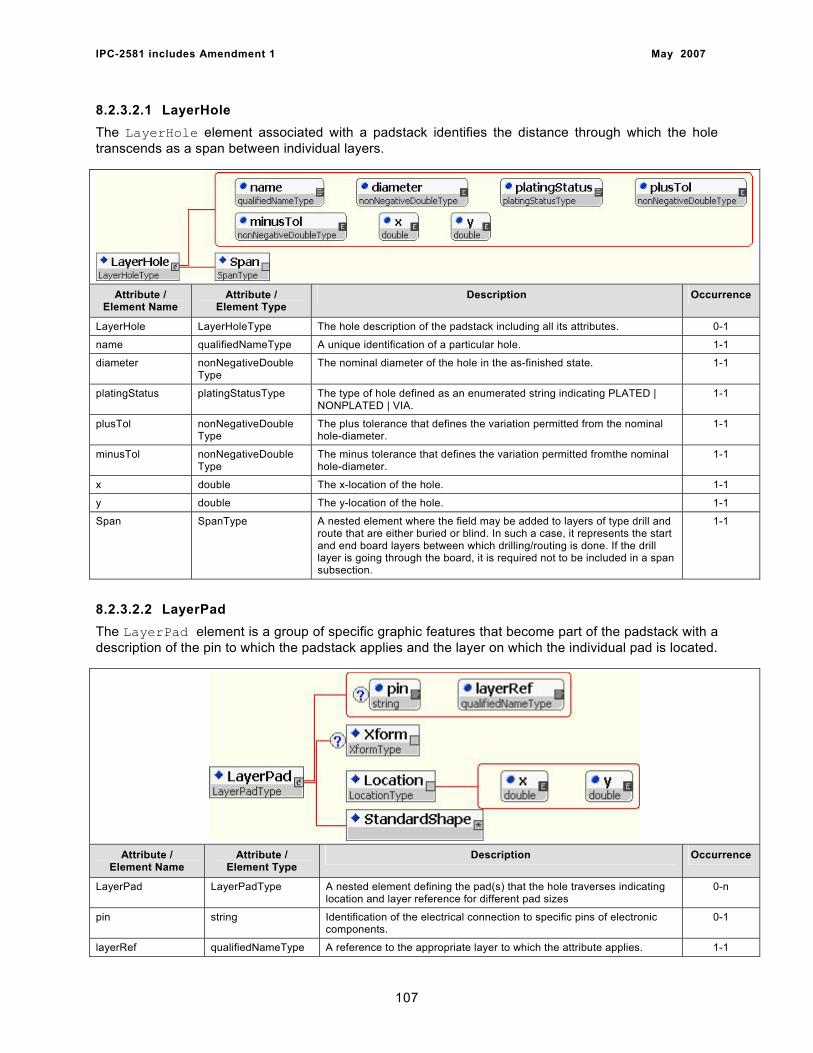
IPC-2581 includes Amendment 1 May 2007
8.2.3.2.1 LayerHole The LayerHole element associated with a padstack identifies the distance through which the hole transcends as a span between individual layers.
Attribute /
Element Name Attribute /
Element Type Description Occurrence
LayerHole LayerHoleType The hole description of the padstack including all its attributes. 0-1
name qualifiedNameType A unique identification of a particular hole. 1-1
diameter nonNegativeDouble Type
The nominal diameter of the hole in the as-finished state. 1-1
platingStatus platingStatusType The type of hole defined as an enumerated string indicating PLATED | NONPLATED | VIA.
1-1
plusTol nonNegativeDouble Type
The plus tolerance that defines the variation permitted from the nominal hole-diameter.
1-1
minusTol nonNegativeDouble Type
The minus tolerance that defines the variation permitted fromthe nominal hole-diameter.
1-1
x double The x-location of the hole. 1-1
y double The y-location of the hole. 1-1
Span SpanType A nested element where the field may be added to layers of type drill and route that are either buried or blind. In such a case, it represents the start and end board layers between which drilling/routing is done. If the drill layer is going through the board, it is required not to be included in a span subsection.
1-1
8.2.3.2.2 LayerPad The LayerPad element is a group of specific graphic features that become part of the padstack with a description of the pin to which the padstack applies and the layer on which the individual pad is located.
Attribute /
Element Name Attribute /
Element Type Description Occurrence
LayerPad LayerPadType A nested element defining the pad(s) that the hole traverses indicating location and layer reference for different pad sizes
0-n
pin string Identification of the electrical connection to specific pins of electronic components.
0-1
layerRef qualifiedNameType A reference to the appropriate layer to which the attribute applies. 1-1
107
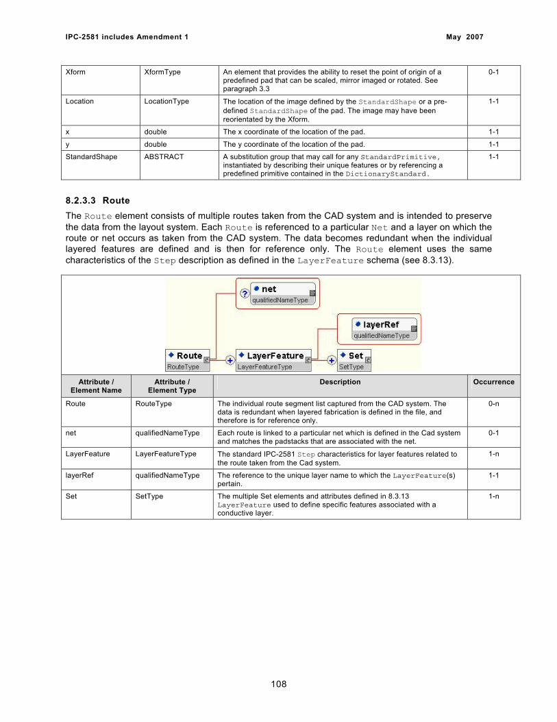
IPC-2581 includes Amendment 1 May 2007
Xform XformType An element that provides the ability to reset the point of origin of a predefined pad that can be scaled, mirror imaged or rotated. See paragraph 3.3
0-1
Location LocationType The location of the image defined by the StandardShape or a pre-defined StandardShape of the pad. The image may have been reorientated by the Xform.
1-1
x double The x coordinate of the location of the pad. 1-1
y double The y coordinate of the location of the pad. 1-1
StandardShape ABSTRACT A substitution group that may call for any StandardPrimitive, instantiated by describing their unique features or by referencing a predefined primitive contained in the DictionaryStandard.
1-1
8.2.3.3 Route The Route element consists of multiple routes taken from the CAD system and is intended to preserve the data from the layout system. Each Route is referenced to a particular Net and a layer on which the route or net occurs as taken from the CAD system. The data becomes redundant when the individual layered features are defined and is then for reference only. The Route element uses the same characteristics of the Step description as defined in the LayerFeature schema (see 8.3.13).
Attribute / Element Name
Attribute / Element Type
Description Occurrence
Route RouteType The individual route segment list captured from the CAD system. The data is redundant when layered fabrication is defined in the file, and therefore is for reference only.
0-n
net qualifiedNameType Each route is linked to a particular net which is defined in the Cad system and matches the padstacks that are associated with the net.
0-1
LayerFeature LayerFeatureType The standard IPC-2581 Step characteristics for layer features related to the route taken from the Cad system.
1-n
layerRef qualifiedNameType The reference to the unique layer name to which the LayerFeature(s) pertain.
1-1
Set SetType The multiple Set elements and attributes defined in 8.3.13 LayerFeature used to define specific features associated with a conductive layer.
1-n
108
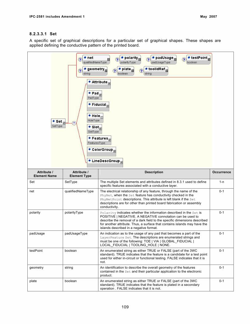
IPC-2581 includes Amendment 1 May 2007
8.2.3.3.1 Set A specific set of graphical descriptions for a particular set of graphical shapes. These shapes are applied defining the conductive pattern of the printed board.
Attribute / Element Name
Attribute / Element Type
Description Occurrence
Set SetType The multiple Set elements and attributes defined in 8.3.1 used to define specific features associated with a conductive layer.
1-n
net qualifiedNameType The electrical relationship of any feature, through the name of the PhyNet, when the Set feature has conductivity checked in the PhyNetPoint descriptions. This attribute is left blank if the Set descriptions are for other than printed board fabrication or assembly conductivity.
0-1
polarity polarityType Polarity indicates whether the information described in the Set is POSITIVE | NEGATIVE. A NEGATIVE connotation can be used to describe the removal of a dark field to the specific dimensions described for another attribute. Thus, a surface that contains islands may have the islands described in a negative format.
0-1
padUsage padUsageType An indication as to the usage of any pad that becomes a part of the LayerFeature Set. The descriptions are enumerated strings and must be one of the following: TOE | VIA | GLOBAL_FIDUCIAL | LOCAL_FIDUCIAL | TOOLING_HOLE | NONE.
0-1
testPoint boolean An enumerated string as either TRUE or FALSE (part of the 3WC standard). TRUE indicates that the feature is a candidate for a test point used for either in-circuit or functional testing. FALSE indicates that it is not.
0-1
geometry string An identification to describe the overall geometry of the features contained in the Set and their particular application to the electronic product.
0-1
plate boolean An enumerated string as either TRUE or FALSE (part of the 3WC standard). TRUE indicates that the feature is plated in a secondary operation . FALSE indicates that it is not.
0-1
109
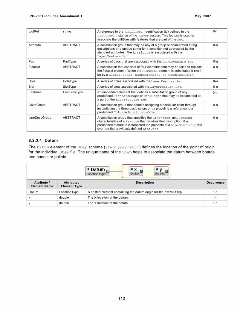
IPC-2581 includes Amendment 1 May 2007
toolRef string A reference to the DrillTool identification (id) defined in the DrillTool instance of the Layer section. This feature is used to associate the drillSize with features that are part of the Set.
0-1
Attribute ABSTRACT A substitution group that may be any of a group of enumerated string descriptions or a unique string for a condition not addressed by the standard attributes. The Attribute is associated with the LayerFeature Set.
0-n
Pad PadType A series of pads that are associated with the LayerFeature Set. 0-n
Fiducial ABSTRACT A substitution that consists of four elements that may be used to replace the fiducial element. When the Fiducial element is substituted it shall be by a Global, Local, BadBoardMark, or GoodPanelMark.
0-n
Hole HoleType A series of holes associated with the LayerFeature Set. 0-n
Slot SlotType A series of slots associated with the LayerFeature Set. 0-n
Features FeaturesType An embedded element that defines a substitution group of any predefined StandardShape or UserShape that may be instantiated as a part of the LayerFeature Set.
0-n
ColorGroup ABSTRACT A substitution group that permits assigning a particular color through instantiating the three basic colors or by providing a reference to a predefined Color in DictionaryColor.
0-n
LineDescGroup ABSTRACT A substitution group that specifies the LineWidth and LineEnd characteristics of a Feature that requires that description. If a predefined feature is instantiated the presents of a LineDescGroup will override the previously defined LineDesc.
0-n
8.2.3.4 Datum The Datum element of the Step schema (StepType/Datum) defines the location of the point of origin for the individual Step file. The unique name of the Step helps to associate the datum between boards and panels or pallets.
Attribute / Element Name
Attribute / Element Type
Description Occurrence
Datum LocationType A nested element containing the datum origin for the overall Step. 1-1
x double The X location of the datum. 1-1
y double The Y location of the datum. 1-1
110
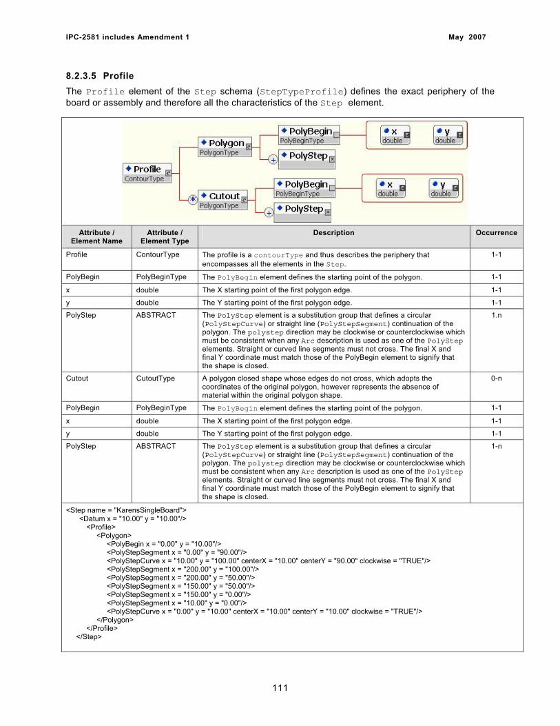
IPC-2581 includes Amendment 1 May 2007
8.2.3.5 Profile The Profile element of the Step schema (StepTypeProfile) defines the exact periphery of the board or assembly and therefore all the characteristics of the Step element.
Attribute / Element Name
Attribute / Element Type
Description Occurrence
Profile ContourType The profile is a contourType and thus describes the periphery that encompasses all the elements in the Step.
1-1
PolyBegin PolyBeginType The PolyBegin element defines the starting point of the polygon. 1-1
x double The X starting point of the first polygon edge. 1-1
y double The Y starting point of the first polygon edge. 1-1
PolyStep ABSTRACT The PolyStep element is a substitution group that defines a circular (PolyStepCurve) or straight line (PolyStepSegment) continuation of the polygon. The polystep direction may be clockwise or counterclockwise which must be consistent when any Arc description is used as one of the PolyStep elements. Straight or curved line segments must not cross. The final X and final Y coordinate must match those of the PolyBegin element to signify that the shape is closed.
1.n
Cutout CutoutType A polygon closed shape whose edges do not cross, which adopts the coordinates of the original polygon, however represents the absence of material within the original polygon shape.
0-n
PolyBegin PolyBeginType The PolyBegin element defines the starting point of the polygon. 1-1
x double The X starting point of the first polygon edge. 1-1
y double The Y starting point of the first polygon edge. 1-1
PolyStep ABSTRACT The PolyStep element is a substitution group that defines a circular (PolyStepCurve) or straight line (PolyStepSegment) continuation of the polygon. The polystep direction may be clockwise or counterclockwise which must be consistent when any Arc description is used as one of the PolyStep elements. Straight or curved line segments must not cross. The final X and final Y coordinate must match those of the PolyBegin element to signify that the shape is closed.
1-n
<Step name = "KarensSingleBoard"> <Datum x = "10.00" y = "10.00"/>
<Profile> <Polygon> <PolyBegin x = "0.00" y = "10.00"/> <PolyStepSegment x = "0.00" y = "90.00"/> <PolyStepCurve x = "10.00" y = "100.00" centerX = "10.00" centerY = "90.00" clockwise = "TRUE"/> <PolyStepSegment x = "200.00" y = "100.00"/> <PolyStepSegment x = "200.00" y = "50.00"/> <PolyStepSegment x = "150.00" y = "50.00"/> <PolyStepSegment x = "150.00" y = "0.00"/> <PolyStepSegment x = "10.00" y = "0.00"/> <PolyStepCurve x = "0.00" y = "10.00" centerX = "10.00" centerY = "10.00" clockwise = "TRUE"/> </Polygon> </Profile> </Step>
111
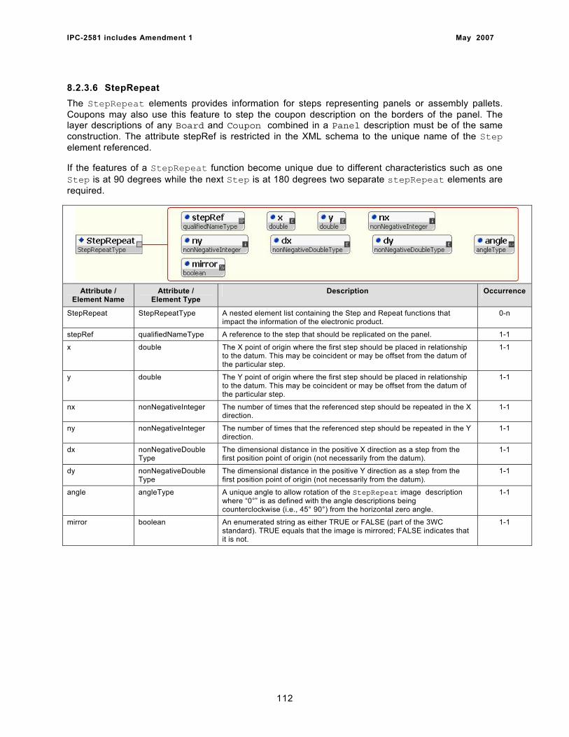
IPC-2581 includes Amendment 1 May 2007
8.2.3.6 StepRepeat The StepRepeat elements provides information for steps representing panels or assembly pallets. Coupons may also use this feature to step the coupon description on the borders of the panel. The layer descriptions of any Board and Coupon combined in a Panel description must be of the same construction. The attribute stepRef is restricted in the XML schema to the unique name of the Step element referenced.
If the features of a StepRepeat function become unique due to different characteristics such as one Step is at 90 degrees while the next Step is at 180 degrees two separate stepRepeat elements are required.
Attribute /
Element Name Attribute /
Element Type Description Occurrence
StepRepeat StepRepeatType A nested element list containing the Step and Repeat functions that impact the information of the electronic product.
0-n
stepRef qualifiedNameType A reference to the step that should be replicated on the panel. 1-1
x double The X point of origin where the first step should be placed in relationship to the datum. This may be coincident or may be offset from the datum of the particular step.
1-1
y double The Y point of origin where the first step should be placed in relationship to the datum. This may be coincident or may be offset from the datum of the particular step.
1-1
nx nonNegativeInteger The number of times that the referenced step should be repeated in the X direction.
1-1
ny nonNegativeInteger The number of times that the referenced step should be repeated in the Y direction.
1-1
dx nonNegativeDouble Type
The dimensional distance in the positive X direction as a step from the first position point of origin (not necessarily from the datum).
1-1
dy nonNegativeDouble Type
The dimensional distance in the positive Y direction as a step from the first position point of origin (not necessarily from the datum).
1-1
angle angleType A unique angle to allow rotation of the StepRepeat image description where “0°” is as defined with the angle descriptions being counterclockwise (i.e., 45° 90°) from the horizontal zero angle.
1-1
mirror boolean An enumerated string as either TRUE or FALSE (part of the 3WC standard). TRUE equals that the image is mirrored; FALSE indicates that it is not.
1-1
112
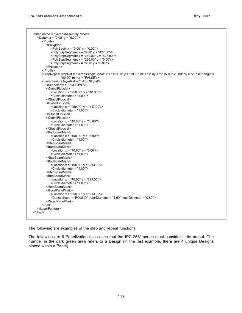
IPC-2581 includes Amendment 1 May 2007
<Step name = "KarensAssemblyPanel"> <Datum x = "0.00" y = "0.00"/> <Profile> <Polygon> <PolyBegin x = "0.00" y = "0.00"/> <PolyStepSegment x = "0.00" y = "427.00"/> <PolyStepSegment x = "260.00" y = "427.00"/> <PolyStepSegment x = "260.00" y = "0.00"/> <PolyStepSegment x = "0.00" y = "0.00"/> </Polygon> </Profile> <StepRepeat stepRef = "KarensSingleBoard" x = "110.00" y = "20.00" nx = "1" ny = "1" dx = "120.00" dy = "207.00" angle = "90.00" mirror = "FALSE"/> <LayerFeature layerRef = "1-Top Signal"> <Set polarity = "POSITIVE"> <GlobalFiducial> <Location x = "250.00" y = "10.00"/> <Circle diameter = "1.00"/> </GlobalFiducial> <GlobalFiducial> <Location x = "250.00" y = "417.00"/> <Circle diameter = "1.00"/> </GlobalFiducial> <GlobalFiducial> <Location x = "10.00" y = "10.00"/> <Circle diameter = "1.00"/> </GlobalFiducial> <BadBoardMark> <Location x = "190.00" y = "5.00"/> <Circle diameter = "1.50"/> </BadBoardMark> <BadBoardMark> <Location x = "70.00" y = "5.00"/> <Circle diameter = "1.00"/> </BadBoardMark> <BadBoardMark> <Location x = "190.00" y = "213.00"/> <Circle diameter = "1.00"/> </BadBoardMark> <BadBoardMark> <Location x = "70.00" y = "213.00"/> <Circle diameter = "1.00"/> </BadBoardMark> <GoodPanelMark> <Location x = "250.00" y = "213.00"/> <Donut shape = "ROUND" outerDiameter = "1.50" innerDiameter = "0.80"/> </GoodPanelMark> </Set> </LayerFeature> </Step>
The following are examples of the step and repeat functions
The following are 6 Panelization use cases that the IPC-258* series must consider in its output. The number in the dark green area refers to a Design (in the last example, there are 4 unique Designs placed within a Panel).
113
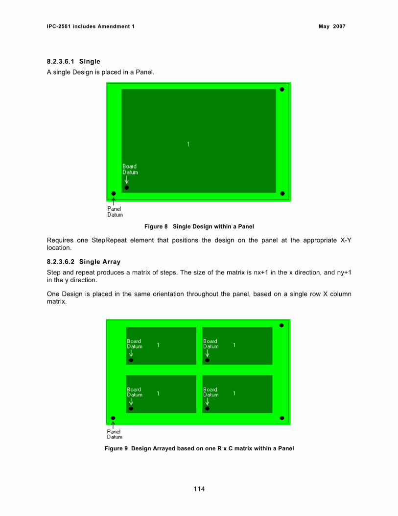
IPC-2581 includes Amendment 1 May 2007
8.2.3.6.1 Single A single Design is placed in a Panel.
Figure 8 Single Design within a Panel
Requires one StepRepeat element that positions the design on the panel at the appropriate X-Y location.
8.2.3.6.2 Single Array Step and repeat produces a matrix of steps. The size of the matrix is nx+1 in the x direction, and ny+1 in the y direction.
One Design is placed in the same orientation throughout the panel, based on a single row X column matrix.
Figure 9 Design Arrayed based on one R x C matrix within a Panel
114
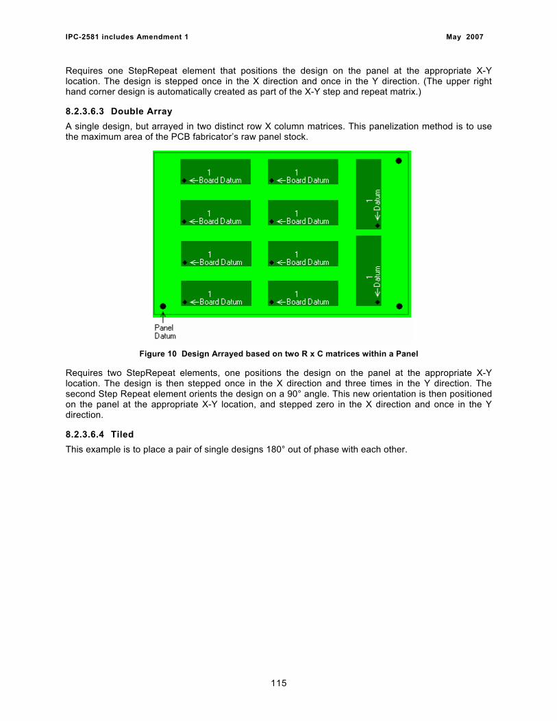
IPC-2581 includes Amendment 1 May 2007
Requires one StepRepeat element that positions the design on the panel at the appropriate X-Y location. The design is stepped once in the X direction and once in the Y direction. (The upper right hand corner design is automatically created as part of the X-Y step and repeat matrix.)
8.2.3.6.3 Double Array A single design, but arrayed in two distinct row X column matrices. This panelization method is to use the maximum area of the PCB fabricator’s raw panel stock.
Figure 10 Design Arrayed based on two R x C matrices within a Panel
Requires two StepRepeat elements, one positions the design on the panel at the appropriate X-Y location. The design is then stepped once in the X direction and three times in the Y direction. The second Step Repeat element orients the design on a 90° angle. This new orientation is then positioned on the panel at the appropriate X-Y location, and stepped zero in the X direction and once in the Y direction.
8.2.3.6.4 Tiled This example is to place a pair of single designs 180° out of phase with each other.
115
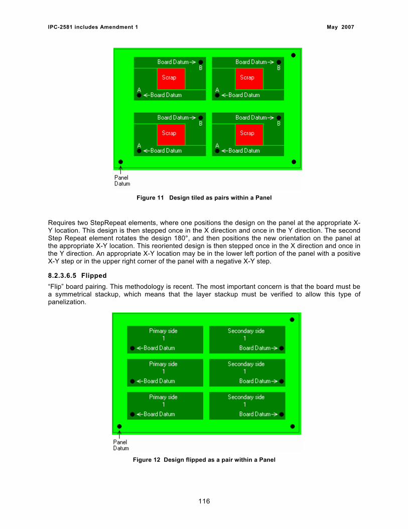
IPC-2581 includes Amendment 1 May 2007
Figure 11 Design tiled as pairs within a Panel
Requires two StepRepeat elements, where one positions the design on the panel at the appropriate X-Y location. This design is then stepped once in the X direction and once in the Y direction. The second Step Repeat element rotates the design 180°, and then positions the new orientation on the panel at the appropriate X-Y location. This reoriented design is then stepped once in the X direction and once in the Y direction. An appropriate X-Y location may be in the lower left portion of the panel with a positive X-Y step or in the upper right corner of the panel with a negative X-Y step.
8.2.3.6.5 Flipped “Flip” board pairing. This methodology is recent. The most important concern is that the board must be a symmetrical stackup, which means that the layer stackup must be verified to allow this type of panelization.
Figure 12 Design flipped as a pair within a Panel
116
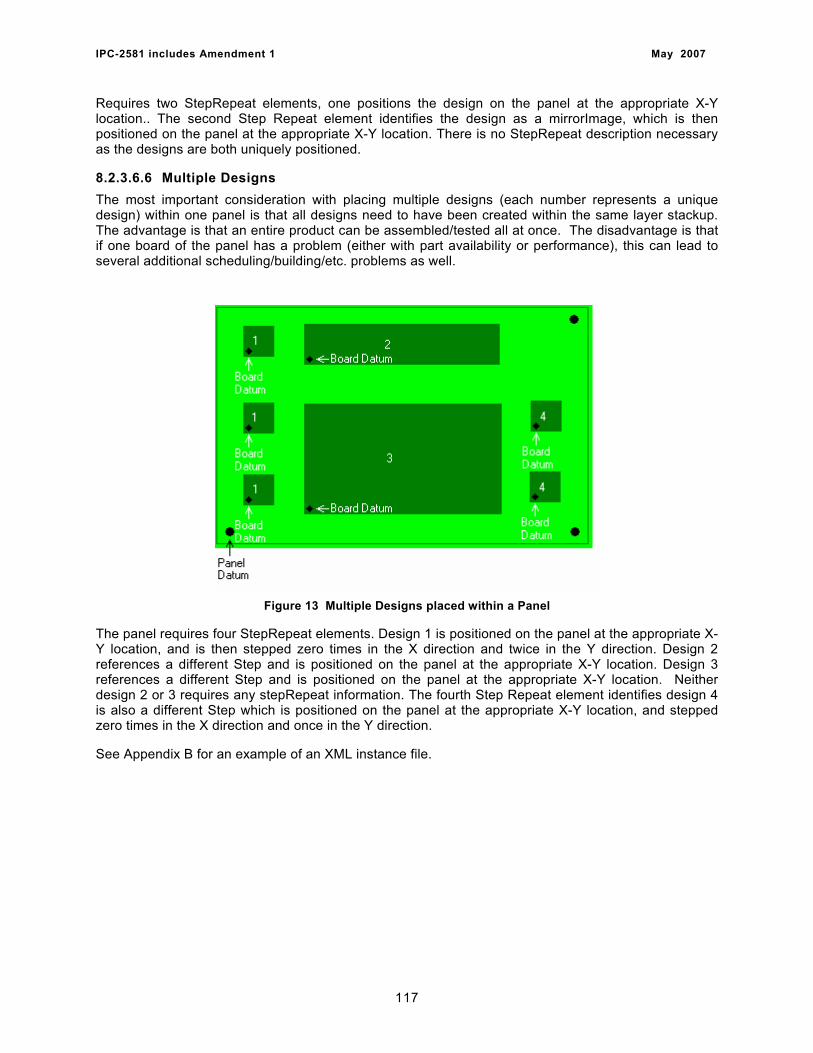
IPC-2581 includes Amendment 1 May 2007
Requires two StepRepeat elements, one positions the design on the panel at the appropriate X-Y location.. The second Step Repeat element identifies the design as a mirrorImage, which is then positioned on the panel at the appropriate X-Y location. There is no StepRepeat description necessary as the designs are both uniquely positioned.
8.2.3.6.6 Multiple Designs The most important consideration with placing multiple designs (each number represents a unique design) within one panel is that all designs need to have been created within the same layer stackup. The advantage is that an entire product can be assembled/tested all at once. The disadvantage is that if one board of the panel has a problem (either with part availability or performance), this can lead to several additional scheduling/building/etc. problems as well.
Figure 13 Multiple Designs placed within a Panel
The panel requires four StepRepeat elements. Design 1 is positioned on the panel at the appropriate X-Y location, and is then stepped zero times in the X direction and twice in the Y direction. Design 2 references a different Step and is positioned on the panel at the appropriate X-Y location. Design 3 references a different Step and is positioned on the panel at the appropriate X-Y location. Neither design 2 or 3 requires any stepRepeat information. The fourth Step Repeat element identifies design 4 is also a different Step which is positioned on the panel at the appropriate X-Y location, and stepped zero times in the X direction and once in the Y direction.
See Appendix B for an example of an XML instance file.
117
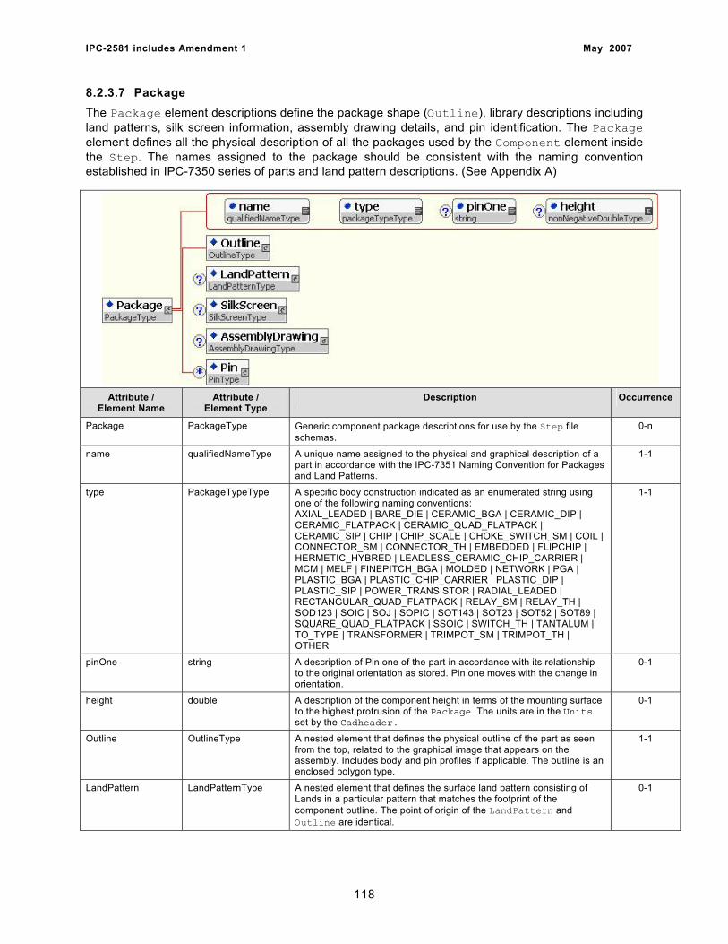
IPC-2581 includes Amendment 1 May 2007
8.2.3.7 Package The Package element descriptions define the package shape (Outline), library descriptions including land patterns, silk screen information, assembly drawing details, and pin identification. The Package element defines all the physical description of all the packages used by the Component element inside the Step. The names assigned to the package should be consistent with the naming convention established in IPC-7350 series of parts and land pattern descriptions. (See Appendix A)
Attribute /
Element Name Attribute /
Element Type Description Occurrence
Package PackageType Generic component package descriptions for use by the Step file schemas.
0-n
name qualifiedNameType A unique name assigned to the physical and graphical description of a part in accordance with the IPC-7351 Naming Convention for Packages and Land Patterns.
1-1
type PackageTypeType A specific body construction indicated as an enumerated string using one of the following naming conventions: AXIAL_LEADED | BARE_DIE | CERAMIC_BGA | CERAMIC_DIP | CERAMIC_FLATPACK | CERAMIC_QUAD_FLATPACK | CERAMIC_SIP | CHIP | CHIP_SCALE | CHOKE_SWITCH_SM | COIL | CONNECTOR_SM | CONNECTOR_TH | EMBEDDED | FLIPCHIP | HERMETIC_HYBRED | LEADLESS_CERAMIC_CHIP_CARRIER | MCM | MELF | FINEPITCH_BGA | MOLDED | NETWORK | PGA | PLASTIC_BGA | PLASTIC_CHIP_CARRIER | PLASTIC_DIP | PLASTIC_SIP | POWER_TRANSISTOR | RADIAL_LEADED | RECTANGULAR_QUAD_FLATPACK | RELAY_SM | RELAY_TH | SOD123 | SOIC | SOJ | SOPIC | SOT143 | SOT23 | SOT52 | SOT89 | SQUARE_QUAD_FLATPACK | SSOIC | SWITCH_TH | TANTALUM | TO_TYPE | TRANSFORMER | TRIMPOT_SM | TRIMPOT_TH | OTHER
1-1
pinOne string A description of Pin one of the part in accordance with its relationship to the original orientation as stored. Pin one moves with the change in orientation.
0-1
height double A description of the component height in terms of the mounting surface to the highest protrusion of the Package. The units are in the Units set by the Cadheader.
0-1
Outline OutlineType A nested element that defines the physical outline of the part as seen from the top, related to the graphical image that appears on the assembly. Includes body and pin profiles if applicable. The outline is an enclosed polygon type.
1-1
LandPattern LandPatternType A nested element that defines the surface land pattern consisting of Lands in a particular pattern that matches the footprint of the component outline. The point of origin of the LandPattern and Outline are identical.
0-1
118
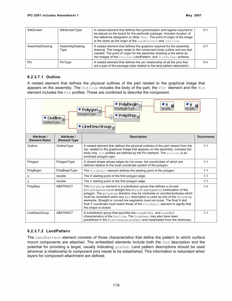
IPC-2581 includes Amendment 1 May 2007
SilkScreen SilkScreenType A nested element that defines the symbolization and legend required to be placed on the board for the particular package. Includes location of the reference designator or other Text. The point of origin of the image is the same as the origin of the LandPattern and Outline.
0-1
AssemblyDrawing AssemblyDrawing Type
A nested element that defines the graphics required for the assembly drawing. The images relate to the component body outline and any text needed. The point of origin for the assembly drawing is the same as the images of the Outline, LandPattern, and SilkScreen schema.
0-1
Pin PinType A nested element that defines the pin relationship of all the pins that are a part of the package style related to the land pattern description.
0-n
8.2.3.7.1 Outline A nested element that defines the physical outlines of the part related to the graphical image that appears on the assembly. The Outline includes the body of the part, the Pin element and the Pin element includes the Pin profiles. These are combined to describe the component.
Attribute /
Element Name Attribute /
Element Type Description Occurrence
Outline OutlineType A nested element that defines the physical outlines of the part viewed from the top, related to the graphical image that appears on the assembly. Includes the body only. Pin profiles are defined by the Pin element. The Outline is an enclosed polygon type.
1-1
Polygon PolygonType A closed shape whose edges do not cross, the coordinates of which are defined relative to the local coordinate system of the polygon.
1-1
PolyBegin PolyBeginType The PolyBegin element defines the starting point of the polygon. 1-1
x double The X starting point of the first polygon edge. 1-1
y double The Y starting point of the first polygon edge. 1-1
PolyStep ABSTRACT The PolyStep element is a substitution group that defines a circular (PolyStepCurve) or straight line (PolyStepSegment) continuation of the polygon. The polystep direction may be clockwise or counterclockwise which must be consistent when any Arc description is used as one of the PolyStep elements. Straight or curved line segments must not cross. The final X and final Y coordinate must match those of the PolyBegin element to signify that the shape is closed.
1-n
LineDescGroup ABSTRACT A substitution group that specifies the LineWidth and LineEnd characteristics of the Outline. The LineDesc may also have been predefined in the DictionaryLineDesc and instantiated from the dictionary.
1-1
8.2.3.7.2 LandPattern The LandPattern element consists of those characteristics that define the pattern to which surface mount components are attached. The embedded elements include both the Pad description and the potential for providing a target, usually indicating pinOne. Land pattern descriptions should be used wherever a relationship to component pins needs to be established. This information is redundant when layers for component attachment are defined.
119
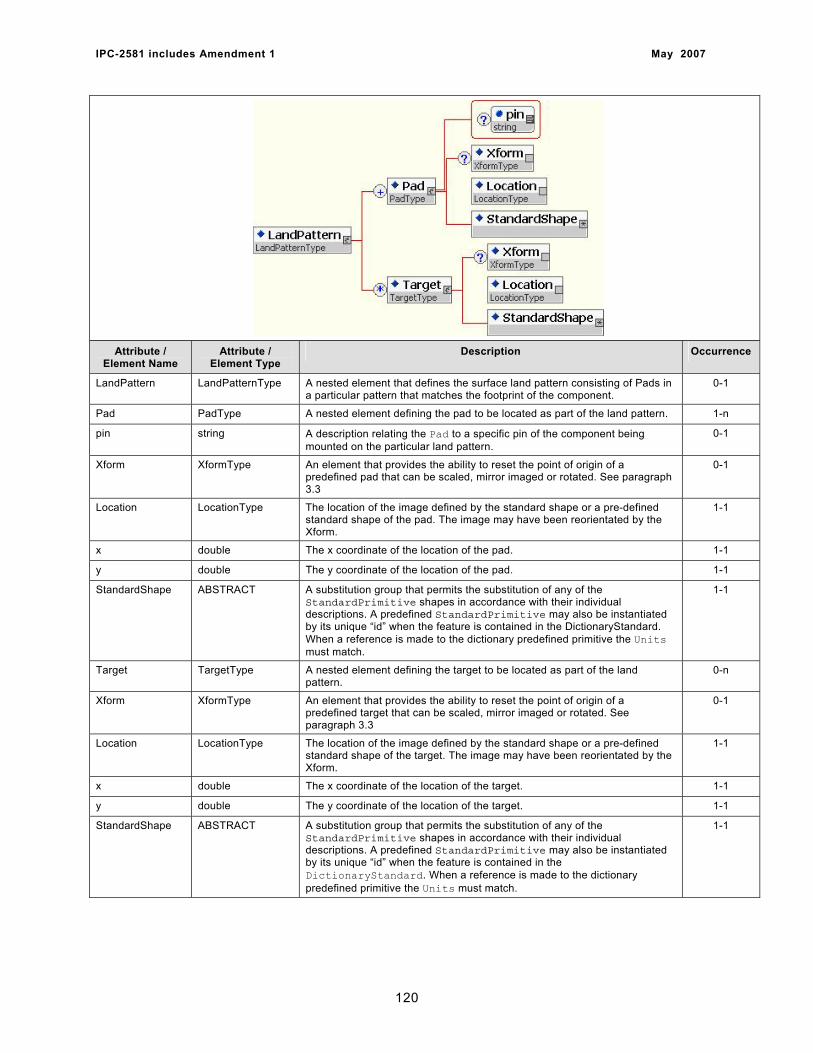
IPC-2581 includes Amendment 1 May 2007
Attribute / Element Name
Attribute / Element Type
Description Occurrence
LandPattern LandPatternType A nested element that defines the surface land pattern consisting of Pads in a particular pattern that matches the footprint of the component.
0-1
Pad PadType A nested element defining the pad to be located as part of the land pattern. 1-n
pin string A description relating the Pad to a specific pin of the component being mounted on the particular land pattern.
0-1
Xform XformType An element that provides the ability to reset the point of origin of a predefined pad that can be scaled, mirror imaged or rotated. See paragraph 3.3
0-1
Location LocationType The location of the image defined by the standard shape or a pre-defined standard shape of the pad. The image may have been reorientated by the Xform.
1-1
x double The x coordinate of the location of the pad. 1-1
y double The y coordinate of the location of the pad. 1-1
StandardShape ABSTRACT A substitution group that permits the substitution of any of the StandardPrimitive shapes in accordance with their individual descriptions. A predefined StandardPrimitive may also be instantiated by its unique “id” when the feature is contained in the DictionaryStandard. When a reference is made to the dictionary predefined primitive the Units must match.
1-1
Target TargetType A nested element defining the target to be located as part of the land pattern.
0-n
Xform XformType An element that provides the ability to reset the point of origin of a predefined target that can be scaled, mirror imaged or rotated. See paragraph 3.3
0-1
Location LocationType The location of the image defined by the standard shape or a pre-defined standard shape of the target. The image may have been reorientated by the Xform.
1-1
x double The x coordinate of the location of the target. 1-1
y double The y coordinate of the location of the target. 1-1
StandardShape ABSTRACT A substitution group that permits the substitution of any of the StandardPrimitive shapes in accordance with their individual descriptions. A predefined StandardPrimitive may also be instantiated by its unique “id” when the feature is contained in the DictionaryStandard. When a reference is made to the dictionary predefined primitive the Units must match.
1-1
120
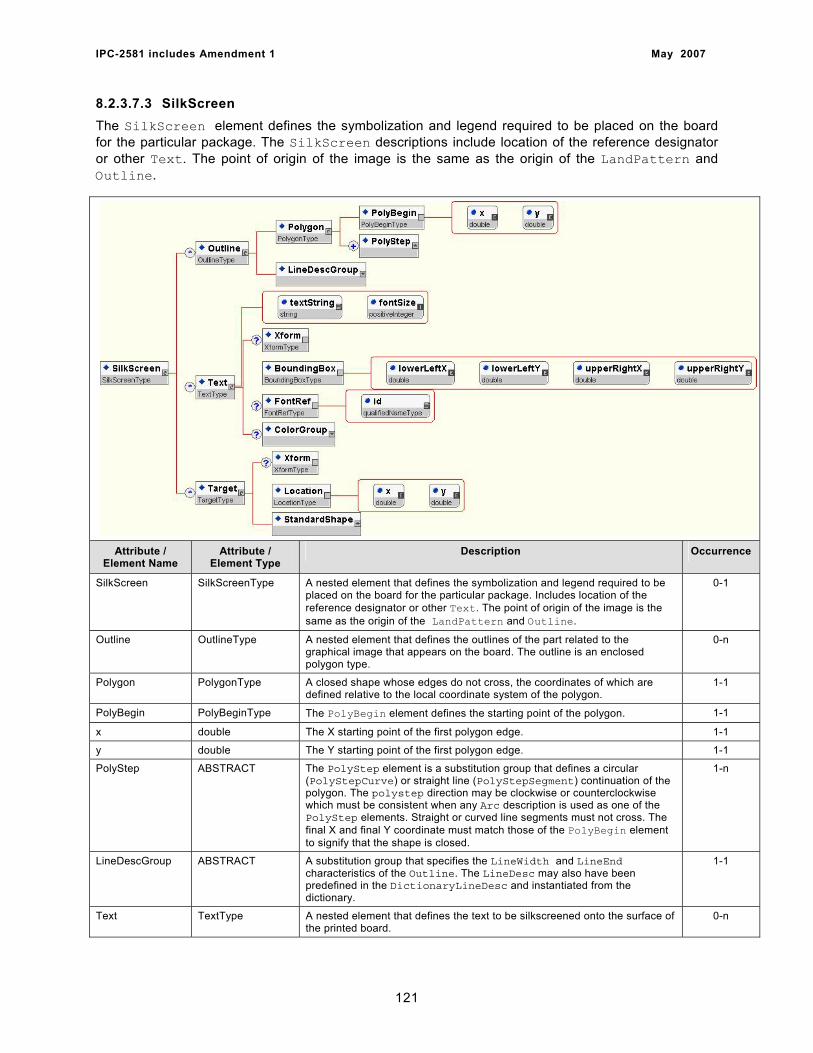
IPC-2581 includes Amendment 1 May 2007
8.2.3.7.3 SilkScreen The SilkScreen element defines the symbolization and legend required to be placed on the board for the particular package. The SilkScreen descriptions include location of the reference designator or other Text. The point of origin of the image is the same as the origin of the LandPattern and Outline.
Attribute / Element Name
Attribute / Element Type
Description Occurrence
SilkScreen SilkScreenType A nested element that defines the symbolization and legend required to be placed on the board for the particular package. Includes location of the reference designator or other Text. The point of origin of the image is the same as the origin of the LandPattern and Outline.
0-1
Outline OutlineType A nested element that defines the outlines of the part related to the graphical image that appears on the board. The outline is an enclosed polygon type.
0-n
Polygon PolygonType A closed shape whose edges do not cross, the coordinates of which are defined relative to the local coordinate system of the polygon.
1-1
PolyBegin PolyBeginType The PolyBegin element defines the starting point of the polygon. 1-1
x double The X starting point of the first polygon edge. 1-1
y double The Y starting point of the first polygon edge. 1-1
PolyStep ABSTRACT The PolyStep element is a substitution group that defines a circular (PolyStepCurve) or straight line (PolyStepSegment) continuation of the polygon. The polystep direction may be clockwise or counterclockwise which must be consistent when any Arc description is used as one of the PolyStep elements. Straight or curved line segments must not cross. The final X and final Y coordinate must match those of the PolyBegin element to signify that the shape is closed.
1-n
LineDescGroup ABSTRACT A substitution group that specifies the LineWidth and LineEnd characteristics of the Outline. The LineDesc may also have been predefined in the DictionaryLineDesc and instantiated from the dictionary.
1-1
Text TextType A nested element that defines the text to be silkscreened onto the surface of the printed board.
0-n
121
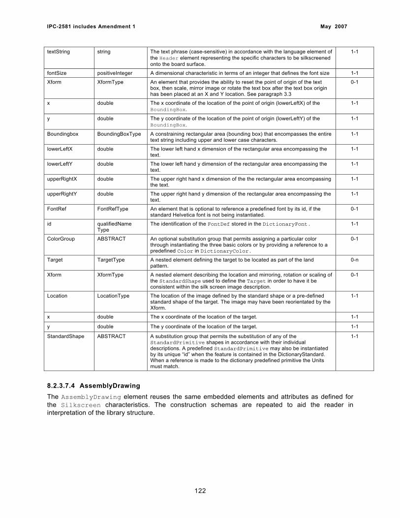
IPC-2581 includes Amendment 1 May 2007
textString string The text phrase (case-sensitive) in accordance with the language element of the Header element representing the specific characters to be silkscreened onto the board surface.
1-1
fontSize positiveInteger A dimensional characteristic in terms of an integer that defines the font size 1-1
Xform XformType An element that provides the ability to reset the point of origin of the text box, then scale, mirror image or rotate the text box after the text box origin has been placed at an X and Y location. See paragraph 3.3
0-1
x double The x coordinate of the location of the point of origin (lowerLeftX) of the BoundingBox.
1-1
y double The y coordinate of the location of the point of origin (lowerLeftY) of the BoundingBox.
1-1
Boundingbox BoundingBoxType A constraining rectangular area (bounding box) that encompasses the entire text string including upper and lower case characters.
1-1
lowerLeftX double The lower left hand x dimension of the rectangular area encompassing the text.
1-1
lowerLeftY double The lower left hand y dimension of the rectangular area encompassing the text.
1-1
upperRightX double The upper right hand x dimension of the the rectangular area encompassing the text.
1-1
upperRightY double The upper right hand y dimension of the rectangular area encompassing the text.
1-1
FontRef FontRefType An element that is optional to reference a predefined font by its id, if the standard Helvetica font is not being instantiated.
0-1
id qualifiedName Type
The identification of the FontDef stored in the DictionaryFont. 1-1
ColorGroup ABSTRACT An optional substitution group that permits assigning a particular color through instantiating the three basic colors or by providing a reference to a predefined Color in DictionaryColor.
0-1
Target TargetType A nested element defining the target to be located as part of the land pattern.
0-n
Xform XformType A nested element describing the location and mirroring, rotation or scaling of the StandardShape used to define the Target in order to have it be consistent within the silk screen image description.
0-1
Location LocationType The location of the image defined by the standard shape or a pre-defined standard shape of the target. The image may have been reorientated by the Xform.
1-1
x double The x coordinate of the location of the target. 1-1
y double The y coordinate of the location of the target. 1-1
StandardShape ABSTRACT A substitution group that permits the substitution of any of the StandardPrimitive shapes in accordance with their individual descriptions. A predefined StandardPrimitive may also be instantiated by its unique “id” when the feature is contained in the DictionaryStandard. When a reference is made to the dictionary predefined primitive the Units must match.
1-1
8.2.3.7.4 AssemblyDrawing The AssemblyDrawing element reuses the same embedded elements and attributes as defined for the Silkscreen characteristics. The construction schemas are repeated to aid the reader in interpretation of the library structure.
122
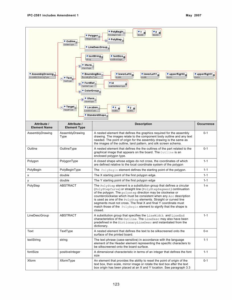
IPC-2581 includes Amendment 1 May 2007
Attribute / Element Name
Attribute / Element Type
Description Occurrence
AssemblyDrawing AssemblyDrawing Type
A nested element that defines the graphics required for the assembly drawing. The images relate to the component body outline and any text needed. The point of origin for the assembly drawing is the same as the images of the outline, land pattern, and silk screen schema.
0-1
Outline OutlineType A nested element that defines the the outlines of the part related to the graphical image that appears on the board. The Outline is an enclosed polygon type.
0-1
Polygon PolygonType A closed shape whose edges do not cross, the coordinates of which are defined relative to the local coordinate system of the polygon
1-1
PolyBegin PolyBeginType The PolyBegin element defines the starting point of the polygon. 1-1
x double The X starting point of the first polygon edge. 1-1
y double The Y starting point of the first polygon edge 1-1
PolyStep ABSTRACT The PolyStep element is a substitution group that defines a circular (PolyStepCurve) or straight line (PolyStepSegment) continuation of the polygon. The polystep direction may be clockwise or counterclockwise which must be consistent when any Arc description is used as one of the PolyStep elements. Straight or curved line segments must not cross. The final X and final Y coordinate must match those of the PolyBegin element to signify that the shape is closed.
1-n
LineDescGroup ABSTRACT A substitution group that specifies the LineWidth and LineEnd characteristics of the Outline. The LineDesc may also have been predefined in the DictionaryLineDesc and instantiated from the dictionary.
1-1
Text TextType A nested element that defines the text to be silkscreened onto the surface of the printed board.
0-n
textString string The text phrase (case-sensitive) in accordance with the language element of the Header element representing the specific characters to be silkscreened onto the board surface.
1-1
fontSize positiveInteger A dimensional characteristic in terms of an integer that defines the font size
1-1
Xform XformType An element that provides the ability to reset the point of origin of the text box, then scale, mirror image or rotate the text box after the text box origin has been placed at an X and Y location. See paragraph 3.3
0-1
123
IPC-2581 includes Amendment 1 May 2007
x double The x coordinate of the location of the point of origin (lowerLeftX) of the BoundingBox.
1-1
y double The y coordinate of the location of the point of origin (lowerLeftY) of the BoundingBox.
1-1
Boundingbox BoundingBoxType A constraining rectangular area (bounding box) that encompasses the entire text string including upper and lower case characters.
1-1
lowerLeftX double The lower left hand x dimension of the rectangular area encompassing the text.
1-1
lowerLeftY double The lower left hand y dimension of the rectangular area encompassing the text.
1-1
UpperRightX double The upper right hand x dimension of the the rectangular area encompassing the text.
1-1
UpperRightY double The upper right hand y dimension of the rectangular area encompassing the text.
1-1
FontRef FontRefType An element that is optional to reference a predefined font by its id, if the standard Helvetica font is not being instantiated.
0-1
id qualifiedNameType The identification of the FontDef stored in the DictionaryFont. 1-1
ColorGroup ABSTRACT An optional substitution group that permits assigning a particular color through instantiating the three basic colors or by providing a reference to a predefined Color in DictionaryColor.
0-1
Target TargetType A nested element defining the target to be located as part of the land pattern.
0-n
Xform XformType A nested element describing the location and mirroring, rotation or scaling of the StandardShape used to define the Target in order to have it be consistent within the AssemblyDrawing description.
0-1
Location LocationType The location of the image defined by the standard shape or a pre-defined standard shape of the pad. The image may have been reorientated by the Xform.
1-1
x double The x coordinate of the location of the target. 1-1
y double The y coordinate of the location of the target. 1-1
StandardShape ABSTRACT A substitution group that permits the substitution of any of the StandardPrimitive shapes in accordance with their individual descriptions. A predefined StandardPrimitive may also be instantiated by its unique “id” when the feature is contained in the DictionaryStandard. When a reference is made to the dictionary predefined primitive the Units must match.
1-1
8.2.3.7.5 Pin The Pin element represents a set of Pin characteristics that are attached to each component package. Each Pin has a number, name, type, electricalType and mountType. Each Pin also contains its relative location and outline.
124
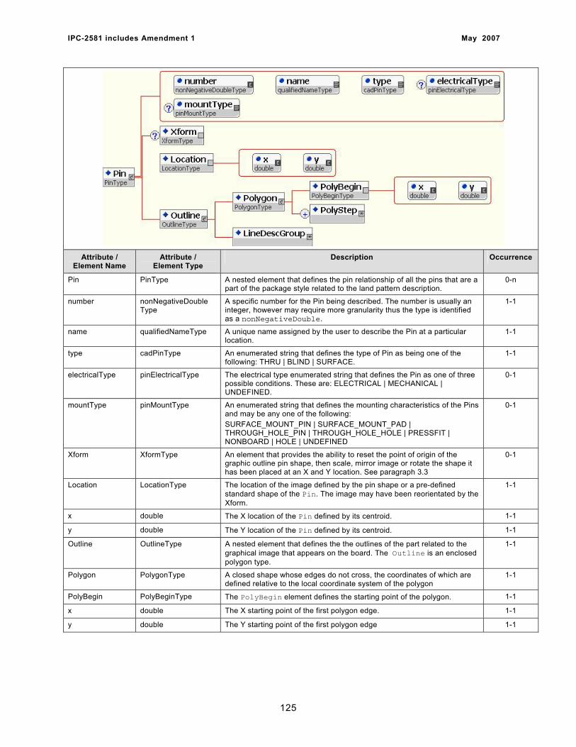
IPC-2581 includes Amendment 1 May 2007
Attribute / Element Name
Attribute / Element Type
Description Occurrence
Pin PinType A nested element that defines the pin relationship of all the pins that are a part of the package style related to the land pattern description.
0-n
number nonNegativeDouble Type
A specific number for the Pin being described. The number is usually an integer, however may require more granularity thus the type is identified as a nonNegativeDouble.
1-1
name qualifiedNameType A unique name assigned by the user to describe the Pin at a particular location.
1-1
type cadPinType An enumerated string that defines the type of Pin as being one of the following: THRU | BLIND | SURFACE.
1-1
electricalType pinElectricalType The electrical type enumerated string that defines the Pin as one of three possible conditions. These are: ELECTRICAL | MECHANICAL | UNDEFINED.
0-1
mountType pinMountType An enumerated string that defines the mounting characteristics of the Pins and may be any one of the following: SURFACE_MOUNT_PIN | SURFACE_MOUNT_PAD | THROUGH_HOLE_PIN | THROUGH_HOLE_HOLE | PRESSFIT | NONBOARD | HOLE | UNDEFINED
0-1
Xform XformType An element that provides the ability to reset the point of origin of the graphic outline pin shape, then scale, mirror image or rotate the shape it has been placed at an X and Y location. See paragraph 3.3
0-1
Location LocationType The location of the image defined by the pin shape or a pre-defined standard shape of the Pin. The image may have been reorientated by the Xform.
1-1
x double The X location of the Pin defined by its centroid. 1-1
y double The Y location of the Pin defined by its centroid. 1-1
Outline OutlineType A nested element that defines the the outlines of the part related to the graphical image that appears on the board. The Outline is an enclosed polygon type.
1-1
Polygon PolygonType A closed shape whose edges do not cross, the coordinates of which are defined relative to the local coordinate system of the polygon
1-1
PolyBegin PolyBeginType The PolyBegin element defines the starting point of the polygon. 1-1
x double The X starting point of the first polygon edge. 1-1
y double The Y starting point of the first polygon edge 1-1
125

IPC-2581 includes Amendment 1 May 2007
PolyStep ABSTRACT The PolyStep element is a substitution group that defines a circular (PolyStepCurve) or straight line (PolyStepSegment) continuation of the polygon. The Polystep direction may be clockwise or counterclockwise which must be consistent when any Arc description is used as one of the PolyStep elements. Straight or curved line segments must not cross. The final X and final Y coordinate must match those of the PolyBegin element to signify that the shape is closed.
1-n
LineDescGroup ABSTRACT A substitution group that specifies the LineWidth and LineEnd characteristics of the Outline. The LineDesc may also have been predefined in the DictionaryLineDesc and instantiated from the dictionary.
1-1
8.2.3.8 Component The Component section contains all the Component elements that were read from the originating CAD system and were captured in the Component element descriptions.
Attribute / Element Name
Attribute / Element Type
Description Occurrence
Component ComponentType A nested element list of component descriptions and their application to the electronic product.
0-n
refDes qualifiedNameType A unique name assigned to the particular component. 1-1
packageRef qualifiedNameType A reference to the package Type used to house the component. 1-1
part string A part description of the part or its electrical/mechanical characteristics. 1-1
layerRef qualifiedNameType The reference to a specific layer element, by its “name” attribute. The layer referenced is where the component or component image should be located. The reference is usually a surface layer, however it may be an internal layer for embedded component attachment.
1-1
mountType mountType The mount type as defined by an enumerated string which may be one of the following: SMT | THMT | OTHER. This attribute can be used to modify the Package description i.e., a through-hole mount modified to be surface mounted.
1-1
weight nonNegativeDouble Type
The weight of the particular component in grams. 0-1
height nonNegativeDouble Type
The height that the top protrusion of the component body is above the surface of the printed board in units assigned in the CadHeader.
0-1
standoff nonNegativeDouble Type
The standoff clearance between the body and the printed board in units assigned in the CadHeader.
0-1
126
IPC-2581 includes Amendment 1 May 2007
Attribute ABSTRACT A substitution group that may be any of a group of enumerated string descriptions or a unique string for a condition not addressed by the standard attributes. The Attribute is associated with the Component description.
0-n
Xform XformType An element that provides the ability to reset the point of origin of a predefined area that can be scaled, mirror imaged or rotated. The image may also by located by the Xform. See paragraph 3.3.
1-1
xOffset double The x offset of a previously defined shape relative to its original point of origin in order to define a new origin used for rotation, mirroring, scaling and location. The CadHeader defines the units of measure.
0-1
yOffset double The y offset of a previously defined shape relative to its original point of origin in order to define a new origin used for rotation, mirroring, scaling and location. The CadHeader defines the units of measure.
0-1
rotation nonNegativeDouble Type
Defines the rotation of a shape about the local origin in degrees. Positive rotation is always counter-clockwise as viewed from the board TOP (primary side). Degree accuracy is expressed as a two place decimal i.e., 45.15; 62.34
0-1
mirror boolean An enumerated string as either TRUE or FALSE (part of the 3WC standard). TRUE equals that the image is mirrored; FALSE indicates that it is not.
0-1
scale scaleType An attribute that defines a “double” dimension whose minExclusiveValue=0.0 representing the multiplication factor of all x and y dimensions. The scale factor does not apply to angular values.
0-1
Location LocationType The location of the component defined by the packageRef or a pre-defined standard shape of the Package. The image may have been reorientated by the Xform.
1-1
x double The x coordinate upon which a features’ point-of-origin is located, relative to the point of origin of the product on which a component is positioned in accordance with the Cartesian coordinate system. The CadHeader defines the units of measure.
1-1
y double The x coordinate upon which a features’ point-of-origin is located, relative to the point of origin of the product on which a component is positioned in accordance with the Cartesian coordinate system. The CadHeader defines the units of measure.
1-1
8.2.3.9 VplPackage The VplPackage element represents information for each component as a new package description that may differ from the original EDA package, thus affecting the shape or the location of the components on the electronic assembly. The details of the VplPackage descriptions contain data regarding other possible matching packages for each component. It should be noted that only one package could be set as chosen for a particular component.
127
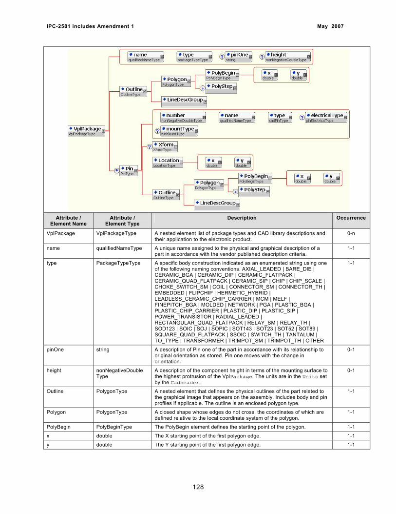
IPC-2581 includes Amendment 1 May 2007
Attribute / Element Name
Attribute / Element Type
Description Occurrence
VplPackage VplPackageType A nested element list of package types and CAD library descriptions and their application to the electronic product.
0-n
name qualifiedNameType A unique name assigned to the physical and graphical description of a part in accordance with the vendor published description criteria.
1-1
type PackageTypeType A specific body construction indicated as an enumerated string using one of the following naming conventions. AXIAL_LEADED | BARE_DIE | CERAMIC_BGA | CERAMIC_DIP | CERAMIC_FLATPACK | CERAMIC_QUAD_FLATPACK | CERAMIC_SIP | CHIP | CHIP_SCALE | CHOKE_SWITCH_SM | COIL | CONNECTOR_SM | CONNECTOR_TH | EMBEDDED | FLIPCHIP | HERMETIC_HYBRID | LEADLESS_CERAMIC_CHIP_CARRIER | MCM | MELF | FINEPITCH_BGA | MOLDED | NETWORK | PGA | PLASTIC_BGA | PLASTIC_CHIP_CARRIER | PLASTIC_DIP | PLASTIC_SIP | POWER_TRANSISTOR | RADIAL_LEADED | RECTANGULAR_QUAD_FLATPACK | RELAY_SM | RELAY_TH | SOD123 | SOIC | SOJ | SOPIC | SOT143 | SOT23 | SOT52 | SOT89 | SQUARE_QUAD_FLATPACK | SSOIC | SWITCH_TH | TANTALUM | TO_TYPE | TRANSFORMER | TRIMPOT_SM | TRIMPOT_TH | OTHER
1-1
pinOne string A description of Pin one of the part in accordance with its relationship to original orientation as stored. Pin one moves with the change in orientation.
0-1
height nonNegativeDouble Type
A description of the component height in terms of the mounting surface to the highest protrusion of the VplPackage. The units are in the Units set by the Cadheader.
0-1
Outline PolygonType A nested element that defines the physical outlines of the part related to the graphical image that appears on the assembly. Includes body and pin profiles if applicable. The outline is an enclosed polygon type.
1-1
Polygon PolygonType A closed shape whose edges do not cross, the coordinates of which are defined relative to the local coordinate system of the polygon.
1-1
PolyBegin PolyBeginType The PolyBegin element defines the starting point of the polygon. 1-1
x double The X starting point of the first polygon edge. 1-1
y double The Y starting point of the first polygon edge. 1-1
128
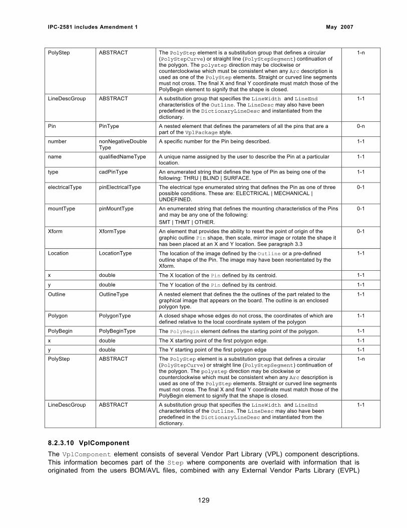
IPC-2581 includes Amendment 1 May 2007
PolyStep ABSTRACT The PolyStep element is a substitution group that defines a circular (PolyStepCurve) or straight line (PolyStepSegment) continuation of the polygon. The polystep direction may be clockwise or counterclockwise which must be consistent when any Arc description is used as one of the PolyStep elements. Straight or curved line segments must not cross. The final X and final Y coordinate must match those of the PolyBegin element to signify that the shape is closed.
1-n
LineDescGroup ABSTRACT A substitution group that specifies the LineWidth and LineEnd characteristics of the Outline. The LineDesc may also have been predefined in the DictionaryLineDesc and instantiated from the dictionary.
1-1
Pin PinType A nested element that defines the parameters of all the pins that are a part of the VplPackage style.
0-n
number nonNegativeDouble Type
A specific number for the Pin being described. 1-1
name qualifiedNameType A unique name assigned by the user to describe the Pin at a particular location.
1-1
type cadPinType An enumerated string that defines the type of Pin as being one of the following: THRU | BLIND | SURFACE.
1-1
electricalType pinElectricalType The electrical type enumerated string that defines the Pin as one of three possible conditions. These are: ELECTRICAL | MECHANICAL | UNDEFINED.
0-1
mountType pinMountType An enumerated string that defines the mounting characteristics of the Pins and may be any one of the following: SMT | THMT | OTHER.
0-1
Xform XformType An element that provides the ability to reset the point of origin of the graphic outline Pin shape, then scale, mirror image or rotate the shape it has been placed at an X and Y location. See paragraph 3.3
0-1
Location LocationType The location of the image defined by the Outline or a pre-defined outline shape of the Pin. The image may have been reorientated by the Xform.
1-1
x double The X location of the Pin defined by its centroid. 1-1
y double The Y location of the Pin defined by its centroid. 1-1
Outline OutlineType A nested element that defines the the outlines of the part related to the graphical image that appears on the board. The outline is an enclosed polygon type.
1-1
Polygon PolygonType A closed shape whose edges do not cross, the coordinates of which are defined relative to the local coordinate system of the polygon
1-1
PolyBegin PolyBeginType The PolyBegin element defines the starting point of the polygon. 1-1
x double The X starting point of the first polygon edge. 1-1
y double The Y starting point of the first polygon edge 1-1
PolyStep ABSTRACT The PolyStep element is a substitution group that defines a circular (PolyStepCurve) or straight line (PolyStepSegment) continuation of the polygon. The polystep direction may be clockwise or counterclockwise which must be consistent when any Arc description is used as one of the PolyStep elements. Straight or curved line segments must not cross. The final X and final Y coordinate must match those of the PolyBegin element to signify that the shape is closed.
1-n
LineDescGroup ABSTRACT A substitution group that specifies the LineWidth and LineEnd characteristics of the Outline. The LineDesc may also have been predefined in the DictionaryLineDesc and instantiated from the dictionary.
1-1
8.2.3.10 VplComponent The VplComponent element consists of several Vendor Part Library (VPL) component descriptions. This information becomes part of the Step where components are overlaid with information that is originated from the users BOM/AVL files, combined with any External Vendor Parts Library (EVPL)
129
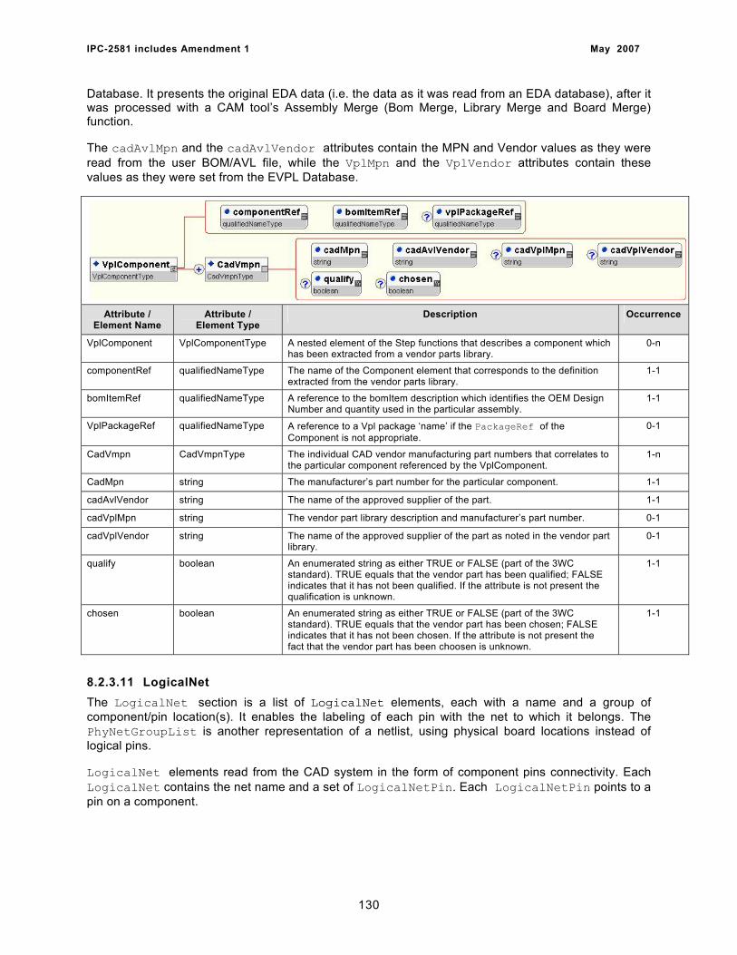
IPC-2581 includes Amendment 1 May 2007
Database. It presents the original EDA data (i.e. the data as it was read from an EDA database), after it was processed with a CAM tool’s Assembly Merge (Bom Merge, Library Merge and Board Merge) function.
The cadAvlMpn and the cadAvlVendor attributes contain the MPN and Vendor values as they were read from the user BOM/AVL file, while the VplMpn and the VplVendor attributes contain these values as they were set from the EVPL Database.
Attribute / Element Name
Attribute / Element Type
Description Occurrence
VplComponent VplComponentType A nested element of the Step functions that describes a component which has been extracted from a vendor parts library.
0-n
componentRef qualifiedNameType The name of the Component element that corresponds to the definition extracted from the vendor parts library.
1-1
bomItemRef qualifiedNameType A reference to the bomItem description which identifies the OEM Design Number and quantity used in the particular assembly.
1-1
VplPackageRef qualifiedNameType A reference to a Vpl package ‘name’ if the PackageRef of the Component is not appropriate.
0-1
CadVmpn CadVmpnType The individual CAD vendor manufacturing part numbers that correlates to the particular component referenced by the VplComponent.
1-n
CadMpn string The manufacturer’s part number for the particular component. 1-1
cadAvlVendor string The name of the approved supplier of the part. 1-1
cadVplMpn string The vendor part library description and manufacturer’s part number. 0-1
cadVplVendor string The name of the approved supplier of the part as noted in the vendor part library.
0-1
qualify boolean An enumerated string as either TRUE or FALSE (part of the 3WC standard). TRUE equals that the vendor part has been qualified; FALSE indicates that it has not been qualified. If the attribute is not present the qualification is unknown.
1-1
chosen boolean An enumerated string as either TRUE or FALSE (part of the 3WC standard). TRUE equals that the vendor part has been chosen; FALSE indicates that it has not been chosen. If the attribute is not present the fact that the vendor part has been choosen is unknown.
1-1
8.2.3.11 LogicalNet The LogicalNet section is a list of LogicalNet elements, each with a name and a group of component/pin location(s). It enables the labeling of each pin with the net to which it belongs. The PhyNetGroupList is another representation of a netlist, using physical board locations instead of logical pins.
LogicalNet elements read from the CAD system in the form of component pins connectivity. Each LogicalNet contains the net name and a set of LogicalNetPin. Each LogicalNetPin points to a pin on a component.
130
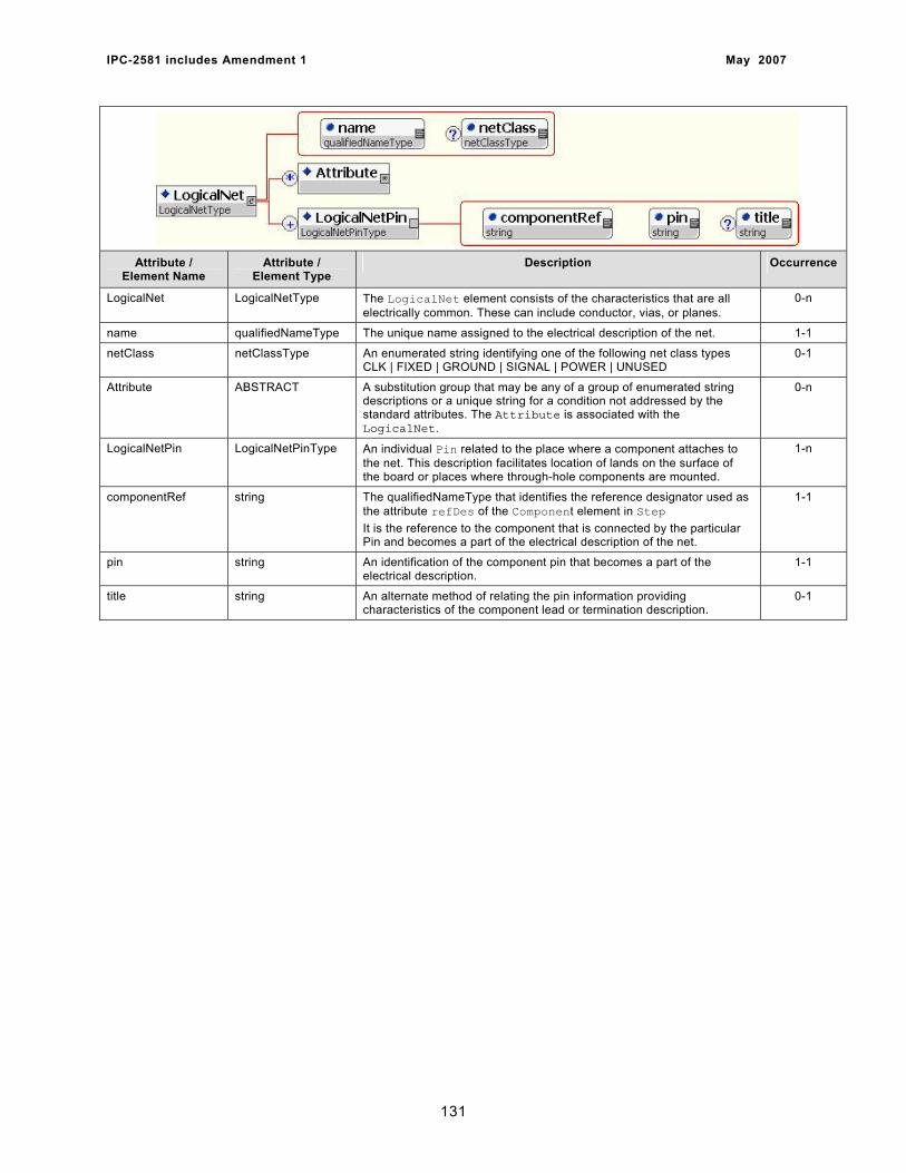
IPC-2581 includes Amendment 1 May 2007
Attribute / Element Name
Attribute / Element Type
Description Occurrence
LogicalNet LogicalNetType The LogicalNet element consists of the characteristics that are all electrically common. These can include conductor, vias, or planes.
0-n
name qualifiedNameType The unique name assigned to the electrical description of the net. 1-1
netClass netClassType An enumerated string identifying one of the following net class types CLK | FIXED | GROUND | SIGNAL | POWER | UNUSED
0-1
Attribute ABSTRACT A substitution group that may be any of a group of enumerated string descriptions or a unique string for a condition not addressed by the standard attributes. The Attribute is associated with the LogicalNet.
0-n
LogicalNetPin LogicalNetPinType An individual Pin related to the place where a component attaches to the net. This description facilitates location of lands on the surface of the board or places where through-hole components are mounted.
1-n
componentRef string The qualifiedNameType that identifies the reference designator used as the attribute refDes of the Component element in Step It is the reference to the component that is connected by the particular Pin and becomes a part of the electrical description of the net.
1-1
pin string An identification of the component pin that becomes a part of the electrical description.
1-1
title string An alternate method of relating the pin information providing characteristics of the component lead or termination description.
0-1
131
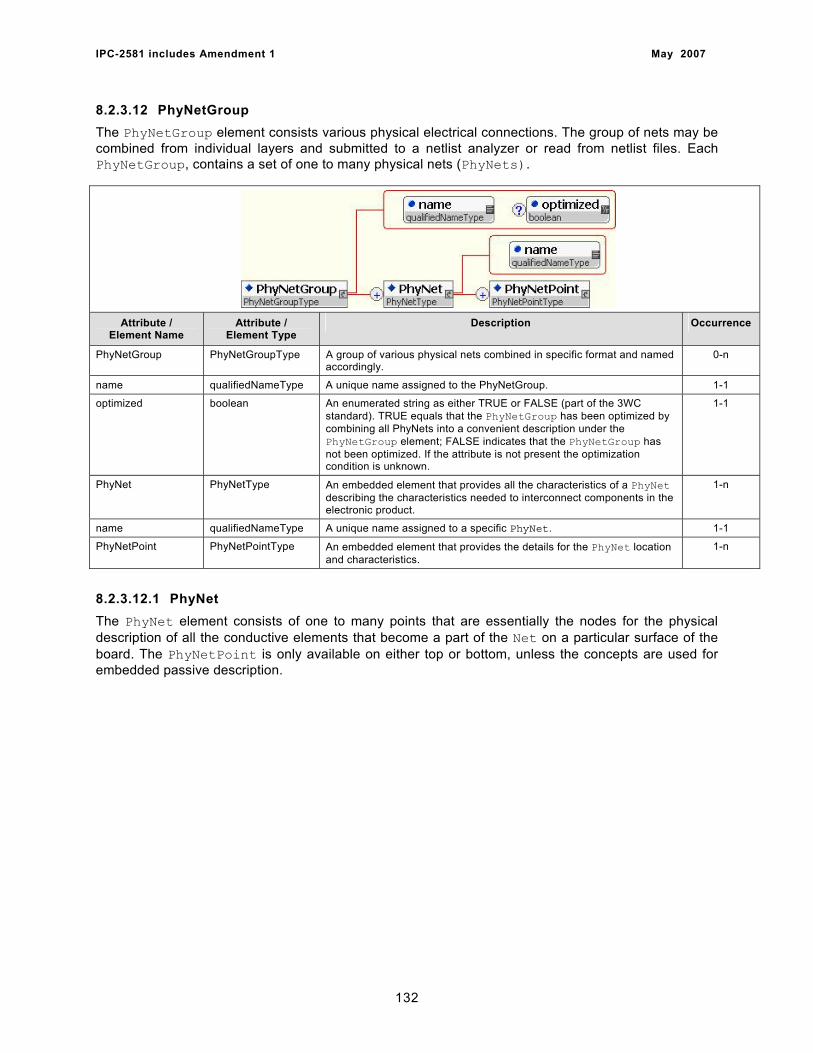
IPC-2581 includes Amendment 1 May 2007
8.2.3.12 PhyNetGroup The PhyNetGroup element consists various physical electrical connections. The group of nets may be combined from individual layers and submitted to a netlist analyzer or read from netlist files. Each PhyNetGroup, contains a set of one to many physical nets (PhyNets).
Attribute / Element Name
Attribute / Element Type
Description Occurrence
PhyNetGroup PhyNetGroupType A group of various physical nets combined in specific format and named accordingly.
0-n
name qualifiedNameType A unique name assigned to the PhyNetGroup. 1-1
optimized boolean An enumerated string as either TRUE or FALSE (part of the 3WC standard). TRUE equals that the PhyNetGroup has been optimized by combining all PhyNets into a convenient description under the PhyNetGroup element; FALSE indicates that the PhyNetGroup has not been optimized. If the attribute is not present the optimization condition is unknown.
1-1
PhyNet PhyNetType An embedded element that provides all the characteristics of a PhyNet describing the characteristics needed to interconnect components in the electronic product.
1-n
name qualifiedNameType A unique name assigned to a specific PhyNet. 1-1
PhyNetPoint PhyNetPointType An embedded element that provides the details for the PhyNet location and characteristics.
1-n
8.2.3.12.1 PhyNet The PhyNet element consists of one to many points that are essentially the nodes for the physical description of all the conductive elements that become a part of the Net on a particular surface of the board. The PhyNetPoint is only available on either top or bottom, unless the concepts are used for embedded passive description.
132
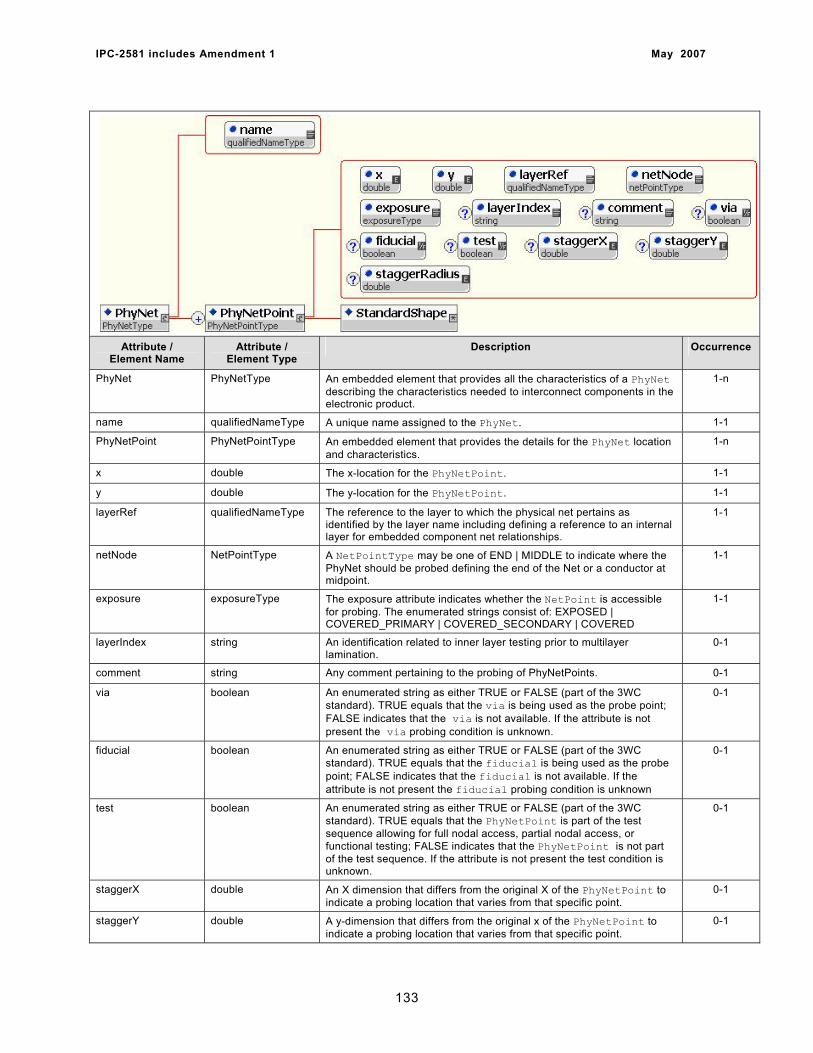
IPC-2581 includes Amendment 1 May 2007
Attribute / Element Name
Attribute / Element Type
Description Occurrence
PhyNet PhyNetType An embedded element that provides all the characteristics of a PhyNet describing the characteristics needed to interconnect components in the electronic product.
1-n
name qualifiedNameType A unique name assigned to the PhyNet. 1-1
PhyNetPoint PhyNetPointType An embedded element that provides the details for the PhyNet location and characteristics.
1-n
x double The x-location for the PhyNetPoint. 1-1
y double The y-location for the PhyNetPoint. 1-1
layerRef qualifiedNameType The reference to the layer to which the physical net pertains as identified by the layer name including defining a reference to an internal layer for embedded component net relationships.
1-1
netNode NetPointType A NetPointType may be one of END | MIDDLE to indicate where the PhyNet should be probed defining the end of the Net or a conductor at midpoint.
1-1
exposure exposureType The exposure attribute indicates whether the NetPoint is accessible for probing. The enumerated strings consist of: EXPOSED | COVERED_PRIMARY | COVERED_SECONDARY | COVERED
1-1
layerIndex string An identification related to inner layer testing prior to multilayer lamination.
0-1
comment string Any comment pertaining to the probing of PhyNetPoints. 0-1
via boolean An enumerated string as either TRUE or FALSE (part of the 3WC standard). TRUE equals that the via is being used as the probe point; FALSE indicates that the via is not available. If the attribute is not present the via probing condition is unknown.
0-1
fiducial boolean An enumerated string as either TRUE or FALSE (part of the 3WC standard). TRUE equals that the fiducial is being used as the probe point; FALSE indicates that the fiducial is not available. If the attribute is not present the fiducial probing condition is unknown
0-1
test boolean An enumerated string as either TRUE or FALSE (part of the 3WC standard). TRUE equals that the PhyNetPoint is part of the test sequence allowing for full nodal access, partial nodal access, or functional testing; FALSE indicates that the PhyNetPoint is not part of the test sequence. If the attribute is not present the test condition is unknown.
0-1
staggerX double An X dimension that differs from the original X of the PhyNetPoint to indicate a probing location that varies from that specific point.
0-1
staggerY double A y-dimension that differs from the original x of the PhyNetPoint to indicate a probing location that varies from that specific point.
0-1
133
IPC-2581 includes Amendment 1 May 2007
staggerRadius double A numerical value that indicates a radius taken from the original x-y point description in the direction of an open conductor that may be probed at its center.
0-1
StandardShape ABSTRACT A substitution group that permits the substitution of any of the StandardPrimitive shapes in accordance with their individual descriptions. A predefined StandardPrimitive may also be instantiated by its unique “id” when the feature is contained in the DictionaryStandard. When a reference is made to the dictionary predefined primitive the Units must match.
1-1
8.2.3.13 LayerFeature The LayerFeature element contains all the physical features located on all layers. These features reference StandardPrimitive or UserPrimitive under the substitution group identification of StandardShape or UserShape. All shapes may be identified through a reference to predefined primitives contained in DictionaryStandard or DictionaryUser. Shapes may also be instantiated in the file by substitution of the Feature element with the shape name. All characteristics of any shape must be present when the substitution takes place.
An individual LayerFeature can be thought of as artwork and these two-dimensional descriptions become the main body of the Step data. The information is contained in LayerFeature elements and includes several different elements, each corresponding to a layer defined earlier in the Layer element.
The Set element defines modal attributes (attributes are in effect for all subsequent graphics contained in the set until changed). The only one important characteristic for the set graphic is the polarity attribute that can be POSITIVE (draw) or NEGATIVE (erase). The existence of negative features is the reason for the importance of the order.
134
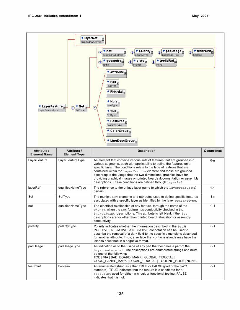
IPC-2581 includes Amendment 1 May 2007
Attribute / Element Name
Attribute / Element Type
Description Occurrence
LayerFeature LayerFeatureType An element that contains various sets of features that are grouped into various segments, each with applicability to define the features on a specific layer. The conditions relate to the type of features that are contained within the LayerFeature element and these are grouped according to the usage that the two-dimensional graphics have for providing graphical images on printed boards documentation or assembly descriptions. These conditions are defined through layerRef.
0-n
layerRef qualifiedNameType The reference to the unique layer name to which the LayerFeature(s) pertain.
1-1
Set SetType The multiple Set elements and attributes used to define specific features associated with a specific layer as identified by the layer contextType.
1-n
net qualifiedNameType The electrical relationship of any feature, through the name of the PhyNet, when the Set feature has conductivity checked in the PhyNetPoint descriptions. This attribute is left blank if the Set descriptions are for other than printed board fabrication or assembly conductivity.
0-1
polarity polarityType Polarity indicates whether the information described in the Set is POSITIVE | NEGATIVE. A NEGATIVE connotation can be used to describe the removal of a dark field to the specific dimensions described for another attribute. Thus, a surface that contains islands may have the islands described in a negative format.
0-1
padUsage padUsageType An indication as to the usage of any pad that becomes a part of the LayerFeature Set. The descriptions are enumerated strings and must be one of the following: TOE | VIA | BAD_BOARD_MARK | GLOBAL_FIDUCIAL | GOOD_PANEL_MARK | LOCAL_FIDUCIAL | TOOLING_HOLE | NONE.
0-1
testPoint boolean An enumerated string as either TRUE or FALSE (part of the 3WC standard). TRUE indicates that the feature is a candidate for a testPoint used for either in-circuit or functional testing. FALSE indicates that it is not.
0-1
135
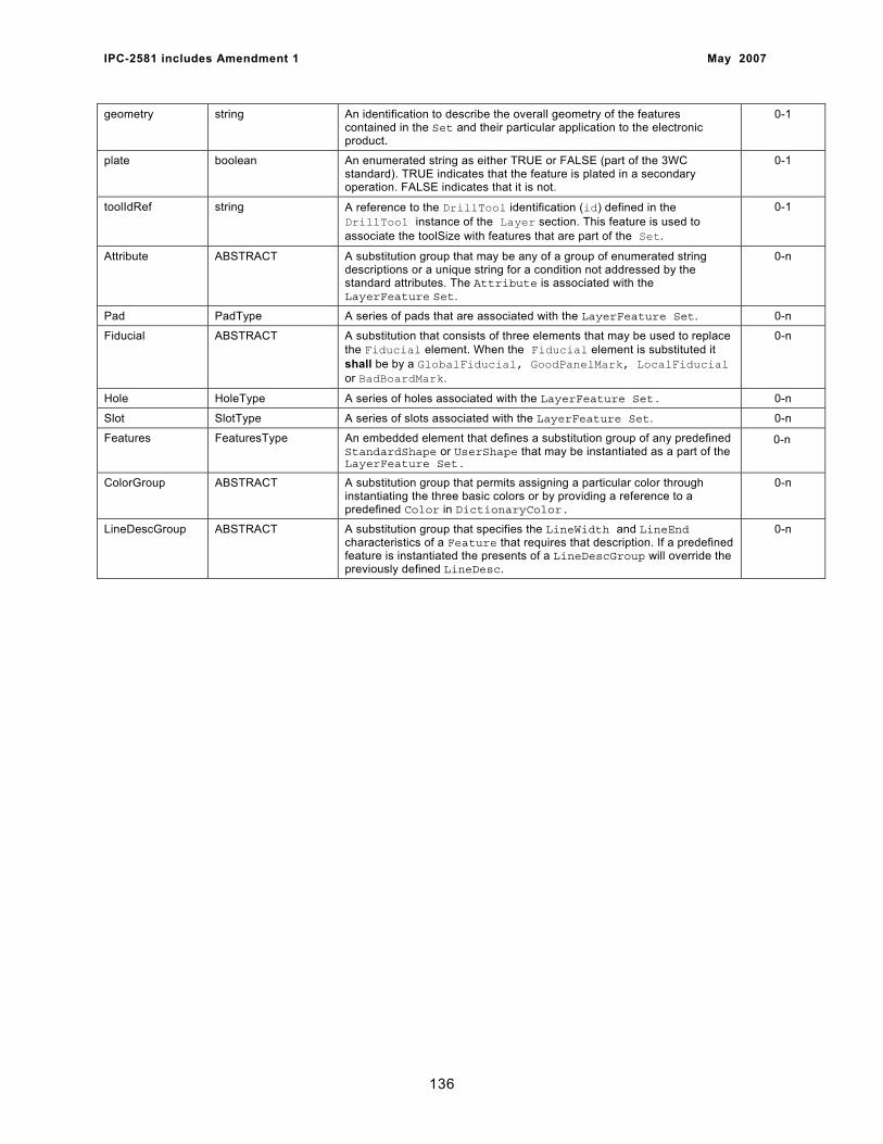
IPC-2581 includes Amendment 1 May 2007
geometry string An identification to describe the overall geometry of the features contained in the Set and their particular application to the electronic product.
0-1
plate boolean An enumerated string as either TRUE or FALSE (part of the 3WC standard). TRUE indicates that the feature is plated in a secondary operation. FALSE indicates that it is not.
0-1
toolIdRef string A reference to the DrillTool identification (id) defined in the DrillTool instance of the Layer section. This feature is used to associate the toolSize with features that are part of the Set.
0-1
Attribute ABSTRACT A substitution group that may be any of a group of enumerated string descriptions or a unique string for a condition not addressed by the standard attributes. The Attribute is associated with the LayerFeature Set.
0-n
Pad PadType A series of pads that are associated with the LayerFeature Set. 0-n
Fiducial ABSTRACT A substitution that consists of three elements that may be used to replace the Fiducial element. When the Fiducial element is substituted it shall be by a GlobalFiducial, GoodPanelMark, LocalFiducial or BadBoardMark.
0-n
Hole HoleType A series of holes associated with the LayerFeature Set. 0-n
Slot SlotType A series of slots associated with the LayerFeature Set. 0-n
Features FeaturesType An embedded element that defines a substitution group of any predefined StandardShape or UserShape that may be instantiated as a part of the LayerFeature Set.
0-n
ColorGroup ABSTRACT A substitution group that permits assigning a particular color through instantiating the three basic colors or by providing a reference to a predefined Color in DictionaryColor.
0-n
LineDescGroup ABSTRACT A substitution group that specifies the LineWidth and LineEnd characteristics of a Feature that requires that description. If a predefined feature is instantiated the presents of a LineDescGroup will override the previously defined LineDesc.
0-n
136
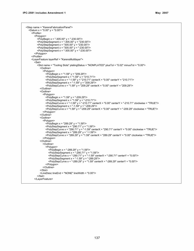
IPC-2581 includes Amendment 1 May 2007
<Step name = "KarensFabricationPanel"> <Datum x = "0.00" y = "0.00"/> <Profile> <Polygon> <PolyBegin x = "-305.00" y = "-230.00"/> <PolyStepSegment x = "-305.00" y = "230.00"/> <PolyStepSegment x = "305.00" y = "230.00"/> <PolyStepSegment x = "305.00" y = "-230.00"/> <PolyStepSegment x = "-305.00" y = "-230.00"/> </Polygon> </Profile> <LayerFeature layerRef = "KarensMultilayer"> <Set> <Slot name = "Tooling Slots" platingStatus = "NONPLATED" plusTol = "0.02" minusTol = "0.00"> <Outline> <Polygon> <PolyBegin x = "1.59" y = "209.29"/> <PolyStepSegment x = "1.59" y = "210.71"/> <PolyStepCurve x = "-1.59" y = "210.71" centerX = "0.00" centerY = "210.71"/> <PolyStepSegment x = "-1.59" y = "209.29"/> <PolyStepCurve x = "1.59" y = "209.29" centerX = "0.00" centerY = "209.29"/> </Outline> <Outline> <Polygon> <PolyBegin x = "1.59" y = "-209.29"/> <PolyStepSegment x = "1.59" y = "-210.71"/> <PolyStepCurve x = "-1.59" y = "-210.71" centerX = "0.00" centerY = "-210.71" clockwise = "TRUE"/> <PolyStepSegment x = "-1.59" y = "-209.29"/> <PolyStepCurve x = "1.59" y = "-209.29" centerX = "0.00" centerY = "-209.29" clockwise = "TRUE"/> </Polygon> </Outline> <Outline> <Polygon> <PolyBegin x = "289.29" y = "1.59"/> <PolyStepSegment x = "290.71" y = "1.59"/> <PolyStepCurve x = "290.71" y = "-1.59" centerX = "290.71" centerY = "0.00" clockwise = "TRUE"/> <PolyStepSegment x = "289.29" y = "-1.59"/> <PolyStepCurve x = "289.29" y = "1.59" centerX = "289.29" centerY = "0.00" clockwise = "TRUE"/> </Polygon> </Outline> <Outline> <Polygon> <PolyBegin x = "-289.29" y = "1.59"/> <PolyStepSegment x = "-290.71" y = "1.59"/> <PolyStepCurve x = "-290.71" y = "-1.59" centerX = "-290.71" centerY = "0.00"/> <PolyStepSegment x = "-1.59" y = "-289.29"/> <PolyStepCurve x = "-289.29" y = "1.59" centerX = "-289.29" centerY = "0.00"/> </Polygon> </Outline> </Slot> <LineDesc lineEnd = "NONE" lineWidth = "0.00"/> </Set> </LayerFeature>
137
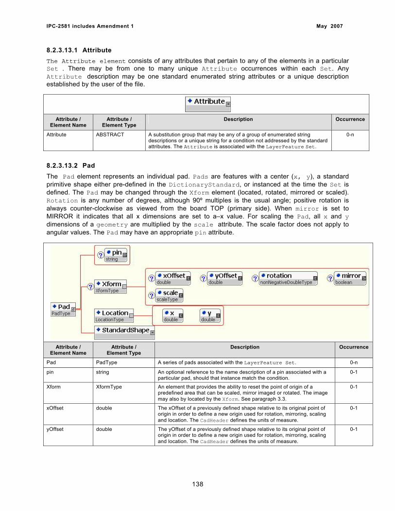
IPC-2581 includes Amendment 1 May 2007
8.2.3.13.1 Attribute The Attribute element consists of any attributes that pertain to any of the elements in a particular Set . There may be from one to many unique Attribute occurrences within each Set. Any Attribute description may be one standard enumerated string attributes or a unique description established by the user of the file.
Attribute / Element Name
Attribute / Element Type
Description Occurrence
Attribute ABSTRACT A substitution group that may be any of a group of enumerated string descriptions or a unique string for a condition not addressed by the standard attributes. The Attribute is associated with the LayerFeature Set.
0-n
8.2.3.13.2 Pad The Pad element represents an individual pad. Pads are features with a center (x, y), a standard primitive shape either pre-defined in the DictionaryStandard, or instanced at the time the Set is defined. The Pad may be changed through the Xform element (located, rotated, mirrored or scaled). Rotation is any number of degrees, although 90º multiples is the usual angle; positive rotation is always counter-clockwise as viewed from the board TOP (primary side). When mirror is set to MIRROR it indicates that all x dimensions are set to a–x value. For scaling the Pad, all x and y dimensions of a geometry are multiplied by the scale attribute. The scale factor does not apply to angular values. The Pad may have an appropriate pin attribute.
Attribute / Element Name
Attribute / Element Type
Description Occurrence
Pad PadType A series of pads associated with the LayerFeature Set. 0-n
pin string An optional reference to the name description of a pin associated with a particular pad, should that instance match the condition.
0-1
Xform XformType An element that provides the ability to reset the point of origin of a predefined area that can be scaled, mirror imaged or rotated. The image may also by located by the Xform. See paragraph 3.3.
0-1
xOffset double The xOffset of a previously defined shape relative to its original point of origin in order to define a new origin used for rotation, mirroring, scaling and location. The CadHeader defines the units of measure.
0-1
yOffset double The yOffset of a previously defined shape relative to its original point of origin in order to define a new origin used for rotation, mirroring, scaling and location. The CadHeader defines the units of measure.
0-1
138
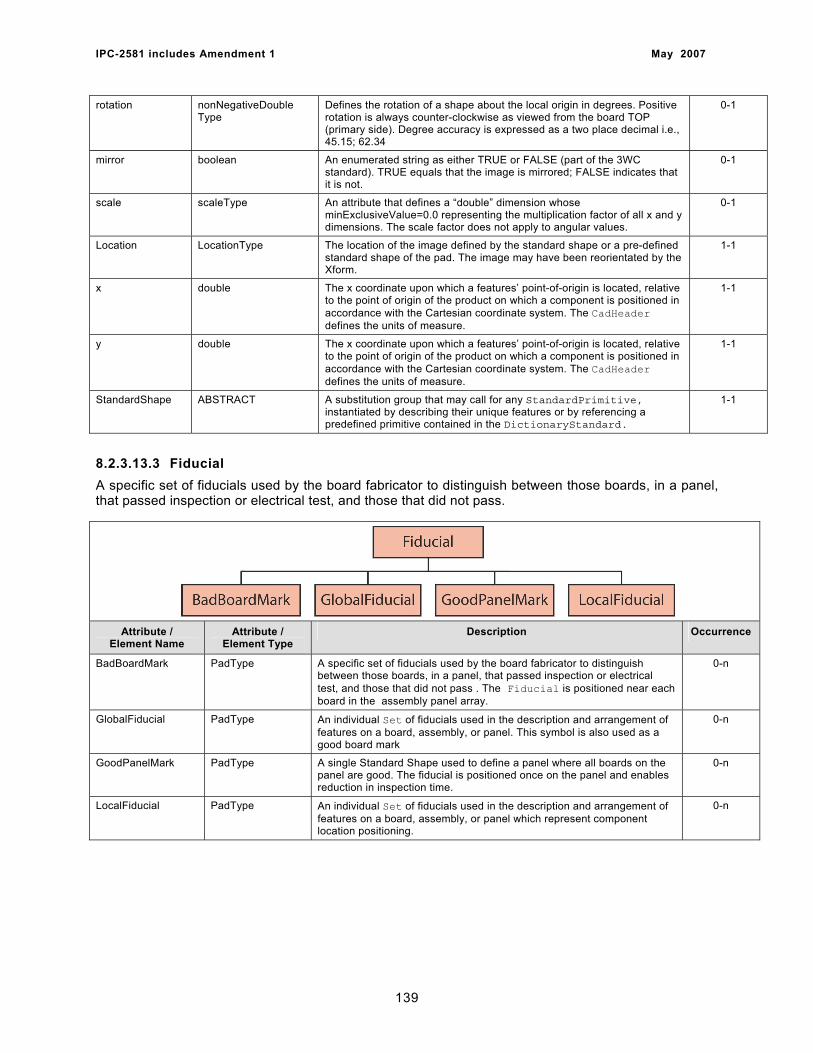
IPC-2581 includes Amendment 1 May 2007
rotation nonNegativeDouble Type
Defines the rotation of a shape about the local origin in degrees. Positive rotation is always counter-clockwise as viewed from the board TOP (primary side). Degree accuracy is expressed as a two place decimal i.e., 45.15; 62.34
0-1
mirror boolean An enumerated string as either TRUE or FALSE (part of the 3WC standard). TRUE equals that the image is mirrored; FALSE indicates that it is not.
0-1
scale scaleType An attribute that defines a “double” dimension whose minExclusiveValue=0.0 representing the multiplication factor of all x and y dimensions. The scale factor does not apply to angular values.
0-1
Location LocationType The location of the image defined by the standard shape or a pre-defined standard shape of the pad. The image may have been reorientated by the Xform.
1-1
x double The x coordinate upon which a features’ point-of-origin is located, relative to the point of origin of the product on which a component is positioned in accordance with the Cartesian coordinate system. The CadHeader defines the units of measure.
1-1
y double The x coordinate upon which a features’ point-of-origin is located, relative to the point of origin of the product on which a component is positioned in accordance with the Cartesian coordinate system. The CadHeader defines the units of measure.
1-1
StandardShape ABSTRACT A substitution group that may call for any StandardPrimitive, instantiated by describing their unique features or by referencing a predefined primitive contained in the DictionaryStandard.
1-1
8.2.3.13.3 Fiducial A specific set of fiducials used by the board fabricator to distinguish between those boards, in a panel, that passed inspection or electrical test, and those that did not pass.
Attribute / Element Name
Attribute / Element Type
Description Occurrence
BadBoardMark PadType A specific set of fiducials used by the board fabricator to distinguish between those boards, in a panel, that passed inspection or electrical test, and those that did not pass . The Fiducial is positioned near each board in the assembly panel array.
0-n
GlobalFiducial PadType An individual Set of fiducials used in the description and arrangement of features on a board, assembly, or panel. This symbol is also used as a good board mark
0-n
GoodPanelMark PadType A single Standard Shape used to define a panel where all boards on the panel are good. The fiducial is positioned once on the panel and enables reduction in inspection time.
0-n
LocalFiducial PadType An individual Set of fiducials used in the description and arrangement of features on a board, assembly, or panel which represent component location positioning.
0-n
139
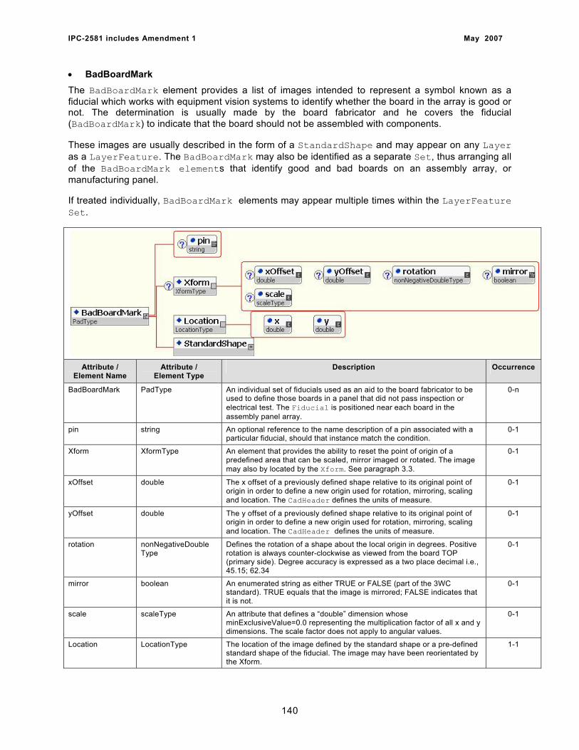
IPC-2581 includes Amendment 1 May 2007
• BadBoardMark The BadBoardMark element provides a list of images intended to represent a symbol known as a fiducial which works with equipment vision systems to identify whether the board in the array is good or not. The determination is usually made by the board fabricator and he covers the fiducial (BadBoardMark) to indicate that the board should not be assembled with components.
These images are usually described in the form of a StandardShape and may appear on any Layer as a LayerFeature. The BadBoardMark may also be identified as a separate Set, thus arranging all of the BadBoardMark elements that identify good and bad boards on an assembly array, or manufacturing panel.
If treated individually, BadBoardMark elements may appear multiple times within the LayerFeature Set.
Attribute / Element Name
Attribute / Element Type
Description Occurrence
BadBoardMark PadType An individual set of fiducials used as an aid to the board fabricator to be used to define those boards in a panel that did not pass inspection or electrical test. The Fiducial is positioned near each board in the assembly panel array.
0-n
pin string An optional reference to the name description of a pin associated with a particular fiducial, should that instance match the condition.
0-1
Xform XformType An element that provides the ability to reset the point of origin of a predefined area that can be scaled, mirror imaged or rotated. The image may also by located by the Xform. See paragraph 3.3.
0-1
xOffset double The x offset of a previously defined shape relative to its original point of origin in order to define a new origin used for rotation, mirroring, scaling and location. The CadHeader defines the units of measure.
0-1
yOffset double The y offset of a previously defined shape relative to its original point of origin in order to define a new origin used for rotation, mirroring, scaling and location. The CadHeader defines the units of measure.
0-1
rotation nonNegativeDouble Type
Defines the rotation of a shape about the local origin in degrees. Positive rotation is always counter-clockwise as viewed from the board TOP (primary side). Degree accuracy is expressed as a two place decimal i.e., 45.15; 62.34
0-1
mirror boolean An enumerated string as either TRUE or FALSE (part of the 3WC standard). TRUE equals that the image is mirrored; FALSE indicates that it is not.
0-1
scale scaleType An attribute that defines a “double” dimension whose minExclusiveValue=0.0 representing the multiplication factor of all x and y dimensions. The scale factor does not apply to angular values.
0-1
Location LocationType The location of the image defined by the standard shape or a pre-defined standard shape of the fiducial. The image may have been reorientated by the Xform.
1-1
140
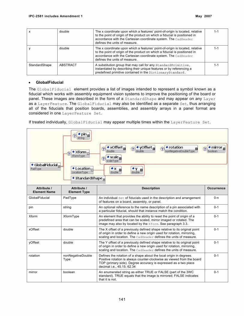
IPC-2581 includes Amendment 1 May 2007
x double The x coordinate upon which a features’ point-of-origin is located, relative to the point of origin of the product on which a fiducial is positioned in accordance with the Cartesian coordinate system. The CadHeader defines the units of measure.
1-1
y double The x coordinate upon which a features’ point-of-origin is located, relative to the point of origin of the product on which a fiducial is positioned in accordance with the Cartesian coordinate system. The CadHeader defines the units of measure.
1-1
StandardShape ABSTRACT A substitution group that may call for any StandardPrimitive, instantiated by describing their unique features or by referencing a predefined primitive contained in the DictionaryStandard.
1-1
• GlobalFiducial The GlobalFiducial element provides a list of images intended to represent a symbol known as a fiducial which works with assembly equipment vision systems to improve the positioning of the board or panel. These images are described in the form of a StandardShape and may appear on any Layer as a LayerFeature. The GlobalFiducial may also be identified as a separate Set, thus arranging all of the fiducials that position boards, assemblies, and assembly arrays in a panel format are considered in one LayerFeature Set.
If treated individually, GlobalFiducial may appear multiple times within the LayerFeature Set.
Attribute / Element Name
Attribute / Element Type
Description Occurrence
GlobalFiducial PadType An individual Set of fiducials used in the description and arrangement of features on a board, assembly, or panel.
0-n
pin string An optional reference to the name description of a pin associated with a particular fiducial, should that instance match the condition.
0-1
Xform XformType An element that provides the ability to reset the point of origin of a predefined area that can be scaled, mirror imaged or rotated. The image may also by located by the Xform. See paragraph 3.3.
0-1
xOffset double The X offset of a previously defined shape relative to its original point of origin in order to define a new origin used for rotation, mirroring, scaling and location. The CadHeader defines the units of measure.
0-1
yOffset double The Y offset of a previously defined shape relative to its original point of origin in order to define a new origin used for rotation, mirroring, scaling and location. The CadHeader defines the units of measure.
0-1
rotation nonNegativeDouble Type
Defines the rotation of a shape about the local origin in degrees. Positive rotation is always counter-clockwise as viewed from the board TOP (primary side). Degree accuracy is expressed as a two place decimal i.e., 45.15; 62.34
0-1
mirror boolean An enumerated string as either TRUE or FALSE (part of the 3WC standard). TRUE equals that the image is mirrored; FALSE indicates that it is not.
0-1
141
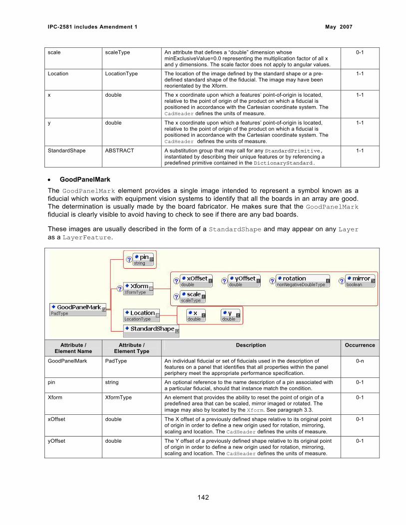
IPC-2581 includes Amendment 1 May 2007
scale scaleType An attribute that defines a “double” dimension whose minExclusiveValue=0.0 representing the multiplication factor of all x and y dimensions. The scale factor does not apply to angular values.
0-1
Location LocationType The location of the image defined by the standard shape or a pre-defined standard shape of the fiducial. The image may have been reorientated by the Xform.
1-1
x double The x coordinate upon which a features’ point-of-origin is located, relative to the point of origin of the product on which a fiducial is positioned in accordance with the Cartesian coordinate system. The CadHeader defines the units of measure.
1-1
y double The x coordinate upon which a features’ point-of-origin is located, relative to the point of origin of the product on which a fiducial is positioned in accordance with the Cartesian coordinate system. The CadHeader defines the units of measure.
1-1
StandardShape ABSTRACT A substitution group that may call for any StandardPrimitive, instantiated by describing their unique features or by referencing a predefined primitive contained in the DictionaryStandard.
1-1
• GoodPanelMark The GoodPanelMark element provides a single image intended to represent a symbol known as a fiducial which works with equipment vision systems to identify that all the boards in an array are good. The determination is usually made by the board fabricator. He makes sure that the GoodPanelMark fiducial is clearly visible to avoid having to check to see if there are any bad boards.
These images are usually described in the form of a StandardShape and may appear on any Layer as a LayerFeature.
Attribute / Element Name
Attribute / Element Type
Description Occurrence
GoodPanelMark PadType An individual fiducial or set of fiducials used in the description of features on a panel that identifies that all properties within the panel periphery meet the appropriate performance specification.
0-n
pin string An optional reference to the name description of a pin associated with a particular fiducial, should that instance match the condition.
0-1
Xform XformType An element that provides the ability to reset the point of origin of a predefined area that can be scaled, mirror imaged or rotated. The image may also by located by the Xform. See paragraph 3.3.
0-1
xOffset double The X offset of a previously defined shape relative to its original point of origin in order to define a new origin used for rotation, mirroring, scaling and location. The CadHeader defines the units of measure.
0-1
yOffset double The Y offset of a previously defined shape relative to its original point of origin in order to define a new origin used for rotation, mirroring, scaling and location. The CadHeader defines the units of measure.
0-1
142
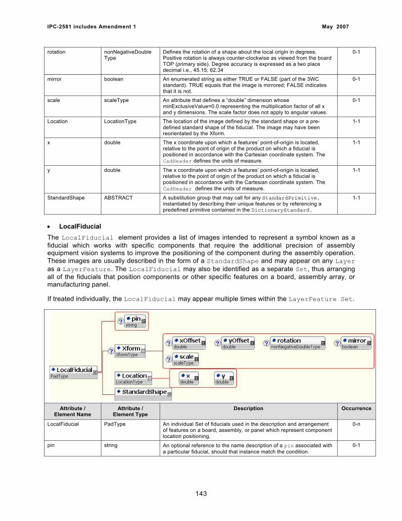
IPC-2581 includes Amendment 1 May 2007
rotation nonNegativeDouble Type
Defines the rotation of a shape about the local origin in degrees. Positive rotation is always counter-clockwise as viewed from the board TOP (primary side). Degree accuracy is expressed as a two place decimal i.e., 45.15; 62.34
0-1
mirror boolean An enumerated string as either TRUE or FALSE (part of the 3WC standard). TRUE equals that the image is mirrored; FALSE indicates that it is not.
0-1
scale scaleType An attribute that defines a “double” dimension whose minExclusiveValue=0.0 representing the multiplication factor of all x and y dimensions. The scale factor does not apply to angular values.
0-1
Location LocationType The location of the image defined by the standard shape or a pre-defined standard shape of the fiducial. The image may have been reorientated by the Xform.
1-1
x double The x coordinate upon which a features’ point-of-origin is located, relative to the point of origin of the product on which a fiducial is positioned in accordance with the Cartesian coordinate system. The CadHeader defines the units of measure.
1-1
y double The x coordinate upon which a features’ point-of-origin is located, relative to the point of origin of the product on which a fiducial is positioned in accordance with the Cartesian coordinate system. The CadHeader defines the units of measure.
1-1
StandardShape ABSTRACT A substitution group that may call for any StandardPrimitive, instantiated by describing their unique features or by referencing a predefined primitive contained in the DictionaryStandard.
1-1
• LocalFiducial The LocalFiducial element provides a list of images intended to represent a symbol known as a fiducial which works with specific components that require the additional precision of assembly equipment vision systems to improve the positioning of the component during the assembly operation. These images are usually described in the form of a StandardShape and may appear on any Layer as a LayerFeature. The LocalFiducial may also be identified as a separate Set, thus arranging all of the fiducials that position components or other specific features on a board, assembly array, or manufacturing panel.
If treated individually, the LocalFiducial may appear multiple times within the LayerFeature Set.
Attribute / Element Name
Attribute / Element Type
Description Occurrence
LocalFiducial PadType An individual Set of fiducials used in the description and arrangement of features on a board, assembly, or panel which represent component location positioning.
0-n
pin string An optional reference to the name description of a pin associated with a particular fiducial, should that instance match the condition.
0-1
143
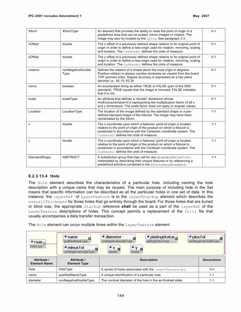
IPC-2581 includes Amendment 1 May 2007
Xform XformType An element that provides the ability to reset the point of origin of a predefined area that can be scaled, mirror imaged or rotated. The image may also by located by the Xform. See paragraph 3.3.
0-1
xOffset double The x offset of a previously defined shape relative to its original point of origin in order to define a new origin used for rotation, mirroring, scaling and location. The CadHeader defines the units of measure.
0-1
yOffset double The y offset of a previously defined shape relative to its original point of origin in order to define a new origin used for rotation, mirroring, scaling and location. The CadHeader defines the units of measure.
0-1
rotation nonNegativeDouble Type
Defines the rotation of a shape about the local origin in degrees. Positive rotation is always counter-clockwise as viewed from the board TOP (primary side). Degree accuracy is expressed as a two place decimal i.e., 45.15; 62.34
0-1
mirror boolean An enumerated string as either TRUE or FALSE (part of the 3WC standard). TRUE equals that the image is mirrored; FALSE indicates that it is not.
0-1
scale scaleType An attribute that defines a “double” dimension whose minExclusiveValue=0.0 representing the multiplication factor of all x and y dimensions. The scale factor does not apply to angular values.
0-1
Location LocationType The location of the image defined by the standard shape or a pre-defined standard shape of the fiducial. The image may have been reorientated by the Xform.
1-1
x double The x coordinate upon which a features’ point-of-origin is located, relative to the point of origin of the product on which a fiducial is positioned in accordance with the Cartesian coordinate system. The CadHeader defines the units of measure.
1-1
y double The x coordinate upon which a features’ point-of-origin is located, relative to the point of origin of the product on which a fiducial is positioned in accordance with the Cartesian coordinate system. The CadHeader defines the units of measure.
1-1
StandardShape ABSTRACT A substitution group that may call for any StandardPrimitive, instantiated by describing their unique features or by referencing a predefined primitive contained in the DictionaryStandard.
1-1
8.2.3.13.4 Hole The Hole element describes the characteristics of a particular hole, including naming the hole description with a unique name that may be reused. The main purpose of including hole in the Set means that specific information can be described as all the particular holes in one set of data. In this instance, the layerRef of LayerFeature is to the Layer/Stackup element which describes the overallThickness for those holes that go entirely through the board. For those holes that are buried or blind vias, the appropriate Stackup reference shall be used as a part of the layerRef of the LayerFeature descriptions of holes. This concept permits a replacement of the Drill file that usually accompanies a data transfer transaction.
The Hole element can occur multiple times within the LayerFeature element.
Attribute / Element Name
Attribute / Element Type
Description Occurrence
Hole HoleType A series of holes associated with the LayerFeature Set. 0-n
name qualifiedNameType A unique identification of a particular hole. 1-1
diameter nonNegativeDoubleType The nominal diameter of the hole in the as-finished state. 1-1
144
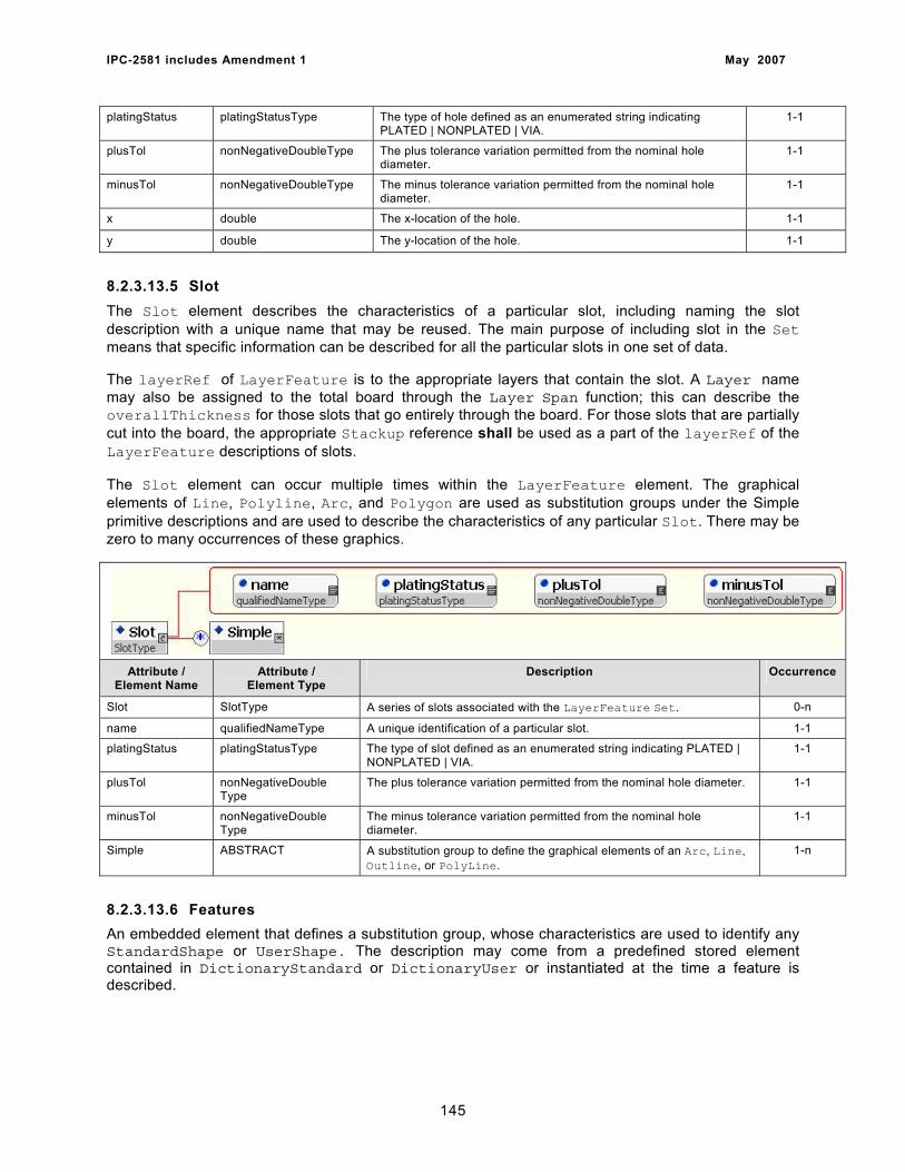
IPC-2581 includes Amendment 1 May 2007
platingStatus platingStatusType The type of hole defined as an enumerated string indicating PLATED | NONPLATED | VIA.
1-1
plusTol nonNegativeDoubleType The plus tolerance variation permitted from the nominal hole diameter.
1-1
minusTol nonNegativeDoubleType The minus tolerance variation permitted from the nominal hole diameter.
1-1
x double The x-location of the hole. 1-1
y double The y-location of the hole. 1-1
8.2.3.13.5 Slot The Slot element describes the characteristics of a particular slot, including naming the slot description with a unique name that may be reused. The main purpose of including slot in the Set means that specific information can be described for all the particular slots in one set of data.
The layerRef of LayerFeature is to the appropriate layers that contain the slot. A Layer name may also be assigned to the total board through the Layer Span function; this can describe the overallThickness for those slots that go entirely through the board. For those slots that are partially cut into the board, the appropriate Stackup reference shall be used as a part of the layerRef of the LayerFeature descriptions of slots.
The Slot element can occur multiple times within the LayerFeature element. The graphical elements of Line, Polyline, Arc, and Polygon are used as substitution groups under the Simple primitive descriptions and are used to describe the characteristics of any particular Slot. There may be zero to many occurrences of these graphics.
Attribute / Element Name
Attribute / Element Type
Description Occurrence
Slot SlotType A series of slots associated with the LayerFeature Set. 0-n
name qualifiedNameType A unique identification of a particular slot. 1-1
platingStatus platingStatusType The type of slot defined as an enumerated string indicating PLATED | NONPLATED | VIA.
1-1
plusTol nonNegativeDouble Type
The plus tolerance variation permitted from the nominal hole diameter. 1-1
minusTol nonNegativeDouble Type
The minus tolerance variation permitted from the nominal hole diameter.
1-1
Simple ABSTRACT A substitution group to define the graphical elements of an Arc, Line, Outline, or PolyLine.
1-n
8.2.3.13.6 Features An embedded element that defines a substitution group, whose characteristics are used to identify any StandardShape or UserShape. The description may come from a predefined stored element contained in DictionaryStandard or DictionaryUser or instantiated at the time a feature is described.
145
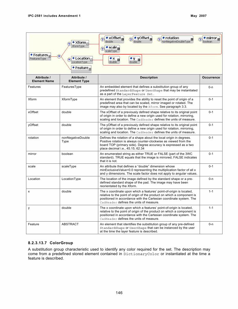
IPC-2581 includes Amendment 1 May 2007
Attribute / Element Name
Attribute / Element Type
Description Occurrence
Features FeaturesType An embedded element that defines a substitution group of any predefined StandardShape or UserShape that may be instantiated as a part of the LayerFeature Set.
0-n
Xform XformType An element that provides the ability to reset the point of origin of a predefined area that can be scaled, mirror imaged or rotated. The image may also by located by the Xform. See paragraph 3.3.
0-1
xOffset double The xOffset of a previously defined shape relative to its original point of origin in order to define a new origin used for rotation, mirroring, scaling and location. The CadHeader defines the units of measure.
0-1
yOffset double The yOffset of a previously defined shape relative to its original point of origin in order to define a new origin used for rotation, mirroring, scaling and location. The CadHeader defines the units of measure.
0-1
rotation nonNegativeDouble Type
Defines the rotation of a shape about the local origin in degrees. Positive rotation is always counter-clockwise as viewed from the board TOP (primary side). Degree accuracy is expressed as a two place decimal i.e., 45.15; 62.34
0-1
mirror boolean An enumerated string as either TRUE or FALSE (part of the 3WC standard). TRUE equals that the image is mirrored; FALSE indicates that it is not.
0-1
scale scaleType An attribute that defines a “double” dimension whose minExclusiveValue=0.0 representing the multiplication factor of all x and y dimensions. The scale factor does not apply to angular values.
0-1
Location LocationType The location of the image defined by the standard shape or a pre-defined standard shape of the pad. The image may have been reorientated by the Xform.
0-n
x double The x coordinate upon which a features’ point-of-origin is located, relative to the point of origin of the product on which a component is positioned in accordance with the Cartesian coordinate system. The CadHeader defines the units of measure.
1-1
y double The x coordinate upon which a features’ point-of-origin is located, relative to the point of origin of the product on which a component is positioned in accordance with the Cartesian coordinate system. The CadHeader defines the units of measure.
1-1
Feature ABSTRACT An element that identifies the substitution group of any pre-defined StandardShape or UserShape that can be instanced by the user at the time the layer feature is described.
0-n
8.2.3.13.7 ColorGroup A substitution group characteristic used to identify any color required for the set. The description may come from a predefined stored element contained in DictionaryColor or instantiated at the time a feature is described.
146
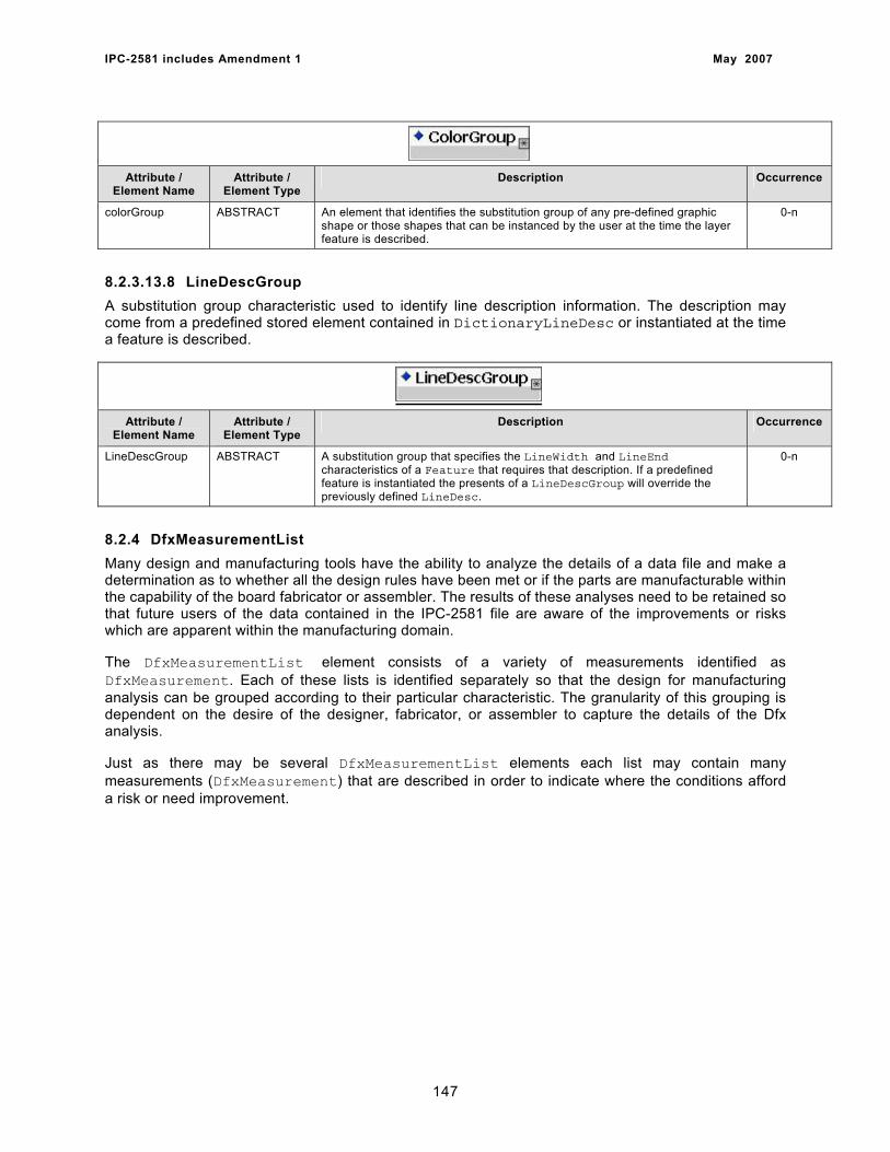
IPC-2581 includes Amendment 1 May 2007
Attribute / Element Name
Attribute / Element Type
Description Occurrence
colorGroup ABSTRACT An element that identifies the substitution group of any pre-defined graphic shape or those shapes that can be instanced by the user at the time the layer feature is described.
0-n
8.2.3.13.8 LineDescGroup A substitution group characteristic used to identify line description information. The description may come from a predefined stored element contained in DictionaryLineDesc or instantiated at the time a feature is described.
Attribute /
Element Name Attribute /
Element Type Description Occurrence
LineDescGroup ABSTRACT A substitution group that specifies the LineWidth and LineEnd characteristics of a Feature that requires that description. If a predefined feature is instantiated the presents of a LineDescGroup will override the previously defined LineDesc.
0-n
8.2.4 DfxMeasurementList Many design and manufacturing tools have the ability to analyze the details of a data file and make a determination as to whether all the design rules have been met or if the parts are manufacturable within the capability of the board fabricator or assembler. The results of these analyses need to be retained so that future users of the data contained in the IPC-2581 file are aware of the improvements or risks which are apparent within the manufacturing domain.
The DfxMeasurementList element consists of a variety of measurements identified as DfxMeasurement. Each of these lists is identified separately so that the design for manufacturing analysis can be grouped according to their particular characteristic. The granularity of this grouping is dependent on the desire of the designer, fabricator, or assembler to capture the details of the Dfx analysis.
Just as there may be several DfxMeasurementList elements each list may contain many measurements (DfxMeasurement) that are described in order to indicate where the conditions afford a risk or need improvement.
147

IPC-2581 includes Amendment 1 May 2007
Attribute / Element Name
Attribute / Element Type
Description Occurrence
DfxMeasurementList DfxMeasurementList Type
An element consisting of a list of all the measurements made in the design for manufacturing analysis grouped in a specific category or criteria description.
1-n
name qualifiedNameType A unique name assigned to the DfmMeasurementList. 1-1
category dfxCategoryType A unique description defined by the user which relates to the products contained in the particular IPC-2581 file intended to provide identification for the group of the DfxMeasurement characteristics. The category type is an enumerated string that may be any of the following groupings COMPONENT | BOARDFAB | ASSEMBLY | TESTING | DATAQUALITY
1-1
criteria double The design criteria used in evaluating the measurement characteristics in order to determine whether the design as supplied by the user meets the manufacturing criteria.
1-1
DfxMeasurement DfxMeasurementType An embedded element that provides the specific details of the measurements that are made on individual layers or product to determine design for manufacturing characteristics.
1-n
8.2.4.1 DfxMeasurement The DfxMeasurement element consists of various measurements that are related to a particular characteristic of the product. The DfxMeasurement’s are made on individual layers or product to determine design for manufacturing characteristics.
Attribute / Element Name
Attribute / Element Type
Description Occurrence
DfxMeasurement DfxMeasurement Type
An embedded element that provides the specific details of the measurements that are made on individual layers or product to determine design for manufacturing characteristics.
1-n
value double The specific value assigned to the DfmResults based on the manufacturing analysis of the design file.
1-1
unitMode unitModeType The mode of measurement depending on the characteristic being evaluated, indicated as an enumerated string using: DISTANCE | AREA | RESISTANCE | CAPACITANCE | IMPEDANCE | PERCENTAGE | SIZE | NONE
1-1
Simple ABSTRACT A substitution group of either an Arc, Line, Outline, or Polyline used to define the characteristics of the Dfx measurement
0-1
148
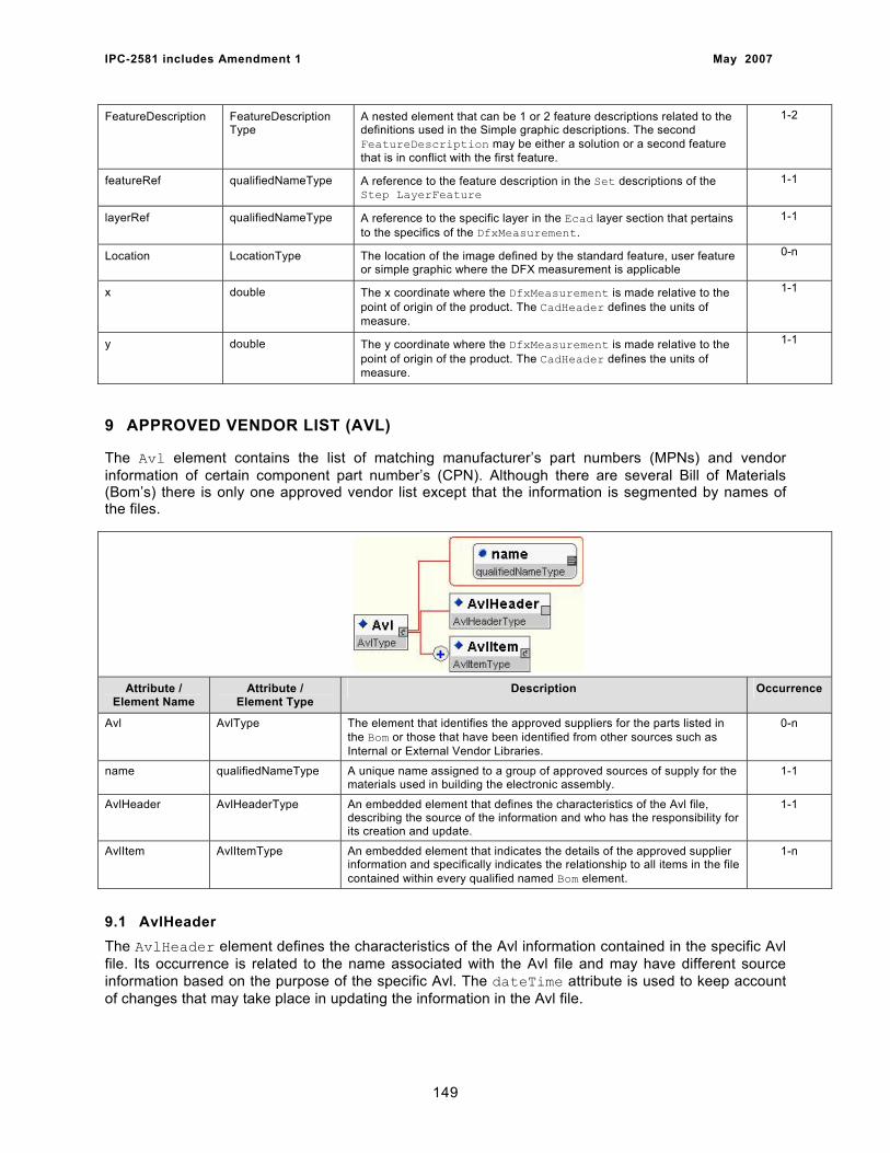
IPC-2581 includes Amendment 1 May 2007
FeatureDescription FeatureDescription Type
A nested element that can be 1 or 2 feature descriptions related to the definitions used in the Simple graphic descriptions. The second FeatureDescription may be either a solution or a second feature that is in conflict with the first feature.
1-2
featureRef qualifiedNameType A reference to the feature description in the Set descriptions of the Step LayerFeature
1-1
layerRef qualifiedNameType A reference to the specific layer in the Ecad layer section that pertains to the specifics of the DfxMeasurement.
1-1
Location LocationType The location of the image defined by the standard feature, user feature or simple graphic where the DFX measurement is applicable
0-n
x double The x coordinate where the DfxMeasurement is made relative to the point of origin of the product. The CadHeader defines the units of measure.
1-1
y double The y coordinate where the DfxMeasurement is made relative to the point of origin of the product. The CadHeader defines the units of measure.
1-1
9 APPROVED VENDOR LIST (AVL)
The Avl element contains the list of matching manufacturer’s part numbers (MPNs) and vendor information of certain component part number’s (CPN). Although there are several Bill of Materials (Bom’s) there is only one approved vendor list except that the information is segmented by names of the files.
Attribute / Element Name
Attribute / Element Type
Description Occurrence
Avl AvlType The element that identifies the approved suppliers for the parts listed in the Bom or those that have been identified from other sources such as Internal or External Vendor Libraries.
0-n
name qualifiedNameType A unique name assigned to a group of approved sources of supply for the materials used in building the electronic assembly.
1-1
AvlHeader AvlHeaderType An embedded element that defines the characteristics of the Avl file, describing the source of the information and who has the responsibility for its creation and update.
1-1
AvlItem AvlItemType An embedded element that indicates the details of the approved supplier information and specifically indicates the relationship to all items in the file contained within every qualified named Bom element.
1-n
9.1 AvlHeader The AvlHeader element defines the characteristics of the Avl information contained in the specific Avl file. Its occurrence is related to the name associated with the Avl file and may have different source information based on the purpose of the specific Avl. The dateTime attribute is used to keep account of changes that may take place in updating the information in the Avl file.
149

IPC-2581 includes Amendment 1 May 2007
Attribute / Element Name
Attribute / Element Type
Description Occurrence
AvlHeader AvlHeaderType An embedded element that defines the characteristics of the Avl file, describing the source of the information and who has the responsibility for its creation and update.
1-1
title string A unique title provided to the AvlHeader that distinguishes the schema instance from the AvlDataHeader.
1-1
source string The source of the information contained in the Avl file. If multiple sources exist they shall be so indicated with the relationship to the Avl data identified.
1-1
author string The individual responsible for the header creation and update. If the responsibility changes the information for this attribute must also change. It is required the person and their enterprise be contained in the LogisticHeader instances and the string name be identical to the id of the Person instance.
1-1
datetime dateTime The date and time that the header was created or modified. 1-1
version positiveInteger A positive number that defines the revision level of the AvlHeader. 1-1
comment string Any comment to assist in the interpretation of the Avl data. 0-1
modRef modRefType A reference to the mode intended for the file transfer. An emunerated string consisting of: FULL | ASSEMBLY | FABRICATION | DESIGN | TEST
0-1
9.2 AvlItem The AvlItem element consists of specific approved vendor information related the Bom data items and the part numbers (OEMDesignNumber) specified by the originator of the IPC-2581 file. Each AvlItem instance starts with its own AvlDataHeader in order to establish the relationship with the appropriate Bom. The grouping of AvlItem’s provides the information on the individual relationship to vendor manufacturing part numbers (AvlVmpnList).
Attribute / Element Name
Attribute / Element Type
Description Occurrence
AvlItem AvlItemType An embedded element that indicates the details of the approved supplier information and specifically indicates the relationship to all items in the file contained within every qualified named Bom element.
1-n
OEMDesignNumber qualifiedNameType The identification of the unique part number used by the OEM customer in the Component XML instance.
1-1
AvlVmpn AvlVmpnType An embedded element that describes an individual approved vendor part number which corresponds to the part selected by the customer and contained in the group of Component’s or, if approved, the VplComponent grouping.
1-n
150
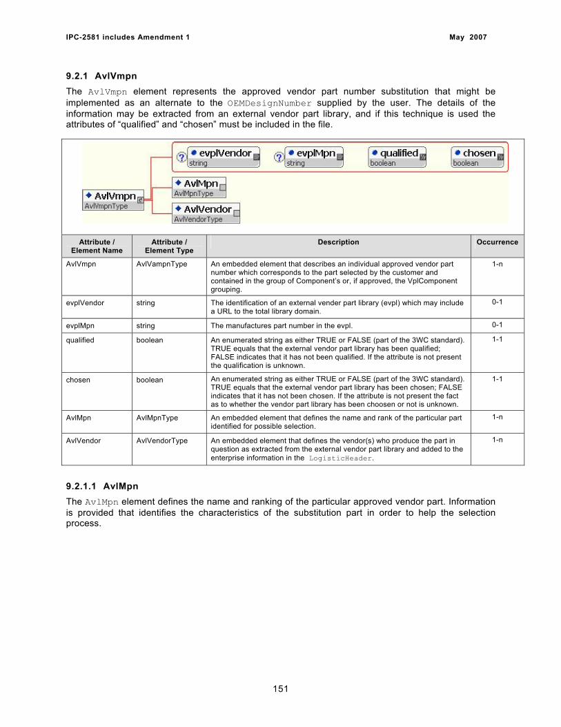
IPC-2581 includes Amendment 1 May 2007
9.2.1 AvlVmpn The AvlVmpn element represents the approved vendor part number substitution that might be implemented as an alternate to the OEMDesignNumber supplied by the user. The details of the information may be extracted from an external vendor part library, and if this technique is used the attributes of “qualified” and “chosen” must be included in the file.
Attribute / Element Name
Attribute / Element Type
Description Occurrence
AvlVmpn AvlVampnType An embedded element that describes an individual approved vendor part number which corresponds to the part selected by the customer and contained in the group of Component’s or, if approved, the VplComponent grouping.
1-n
evplVendor string The identification of an external vender part library (evpl) which may include a URL to the total library domain.
0-1
evplMpn string The manufactures part number in the evpl. 0-1
qualified boolean An enumerated string as either TRUE or FALSE (part of the 3WC standard). TRUE equals that the external vendor part library has been qualified; FALSE indicates that it has not been qualified. If the attribute is not present the qualification is unknown.
1-1
chosen boolean An enumerated string as either TRUE or FALSE (part of the 3WC standard). TRUE equals that the external vendor part library has been chosen; FALSE indicates that it has not been chosen. If the attribute is not present the fact as to whether the vendor part library has been choosen or not is unknown.
1-1
AvlMpn AvlMpnType An embedded element that defines the name and rank of the particular part identified for possible selection.
1-n
AvlVendor AvlVendorType An embedded element that defines the vendor(s) who produce the part in question as extracted from the external vendor part library and added to the enterprise information in the LogisticHeader.
1-n
9.2.1.1 AvlMpn The AvlMpn element defines the name and ranking of the particular approved vendor part. Information is provided that identifies the characteristics of the substitution part in order to help the selection process.
151
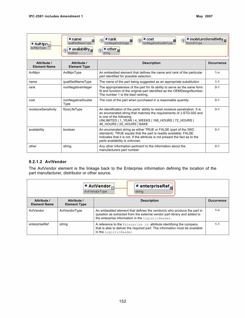
IPC-2581 includes Amendment 1 May 2007
Attribute / Element Name
Attribute / Element Type
Description Occurrence
AvlMpn AvlMpnType An embedded element that defines the name and rank of the particular part identified for possible selection.
1-n
name qualifiedNameType The name of the part being suggested as an appropriate substitution 1-1
rank nonNegativeInteger The appropriateness of the part for its ability to serve as the same form fit and function of the original part identified as the OEMDesignNumber. The number 1 is the best ranking.
0-1
cost nonNegativeDouble Type
The cost of the part when purchased in a reasonable quantity 0-1
moistureSensitivity floorLifeType An identification of the parts’ ability to resist moisture penetration. It is an enumerated string that matches the requirements of J-STD-020 and is one of the following: UNLIMITED | 1_YEAR | 4_WEEKS | 168_HOURS | 72_HOURS | 48_HOURS | 24_HOURS | BAKE
0-1
availability boolean An enumerated string as either TRUE or FALSE (part of the 3WC standard). TRUE equals that the part is readily available; FALSE indicates that it is not. If the attribute is not present the fact as to the parts availability is unknown.
0-1
other string Any other information pertinent to the information about the manufacturers part number
0-1
9.2.1.2 AvlVendor The AvlVendor element is the linkage back to the Enterprise information defining the location of the part manufacturer, distributor or other source.
Attribute / Element Name
Attribute / Element Type
Description Occurrence
AvlVendor AvlVendorType An embedded element that defines the vendor(s) who produce the part in question as extracted from the external vendor part library and added to the enterprise information in the LogisticHeader.
1-n
enterpriseRef string A reference to the Enterprise id attribute identifying the company that is able to deliver the required part. The information must be available in the LogisticHeader
1-1
152
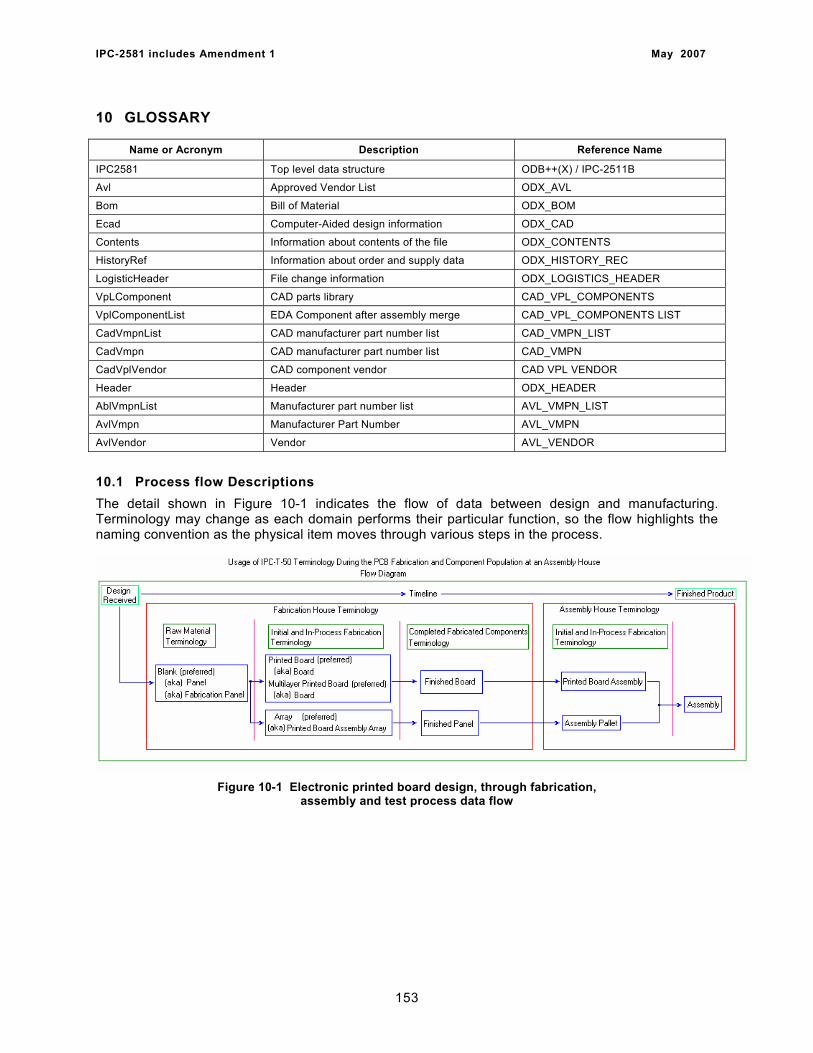
IPC-2581 includes Amendment 1 May 2007
10 GLOSSARY
Name or Acronym Description Reference Name
IPC2581 Top level data structure ODB++(X) / IPC-2511B
Avl Approved Vendor List ODX_AVL
Bom Bill of Material ODX_BOM
Ecad Computer-Aided design information ODX_CAD
Contents Information about contents of the file ODX_CONTENTS
HistoryRef Information about order and supply data ODX_HISTORY_REC
LogisticHeader File change information ODX_LOGISTICS_HEADER
VpLComponent CAD parts library CAD_VPL_COMPONENTS
VplComponentList EDA Component after assembly merge CAD_VPL_COMPONENTS LIST
CadVmpnList CAD manufacturer part number list CAD_VMPN_LIST
CadVmpn CAD manufacturer part number list CAD_VMPN
CadVplVendor CAD component vendor CAD VPL VENDOR
Header Header ODX_HEADER
AblVmpnList Manufacturer part number list AVL_VMPN_LIST
AvlVmpn Manufacturer Part Number AVL_VMPN
AvlVendor Vendor AVL_VENDOR
10.1 Process flow Descriptions The detail shown in Figure 10-1 indicates the flow of data between design and manufacturing. Terminology may change as each domain performs their particular function, so the flow highlights the naming convention as the physical item moves through various steps in the process.
Figure 10-1 Electronic printed board design, through fabrication,
assembly and test process data flow
153
IPC-2581 includes Amendment 1 May 2007
10.2 Terms and Definitions The definition of all terms shall be in accordance with IPC-T-50 and the following. An asterisk (*) by the term indicates that it is a reproduction from IPC-T-50 and is provided to assist the reader in interpretation of this standard. The order of the terms is related to the 2581 process flow shown in 10.1
Blank * 41.1339 An unprocessed or partially processed piece of base material or metal- clad base material, that has been cut from a sheet or panel, that has the rough dimensions of a printed board. (See also ‘‘Panel.’’) Panel 41.1463 A rectangular sheet of base material or metal-clad material of predetermined size that is used for the processing of one or more printed boards and, when required, one or more test coupons. (See also ‘‘Blank.’’) Fabrication Panel A rectangular sheet of base material or metal-clad material of predetermined size that is used by a printed board manufacturer for the processing of one or more printed boards and, when required, one or more test coupons. (See also ‘‘Blank.’’) Board * 60.0118 see ‘‘Printed Board,‘‘ and ‘‘Multilayer Printed Board.’’ Printed Board (PB) * 60.1485 The general term for completely processed printed circuit and printed wiring configurations. (This includes single-sided, double-sided and multilayer boards with rigid, flexible, and rigid-flex base materials.) Multilayer Printed Board * 60.1227 The general term for a printed board that consist of rigid or flexible insulation materials and three or more alternate printed wiring and/or printed circuit layers that have been bonded together and electrically interconnected. Finished Board see “Printed Board” Finished Panel A rectangular sheet of base material or metal-clad material of predetermined size that is used for the processing of one or more printed board designs and, when required, one or more test coupons which is extracted from the fabrication panel to deliver to the customer or to the next level of fabrication. (see Assembly Pallet) Assembly* 80.1327 A number of parts, subassemblies or combinations thereof joined together. (Note: This term can be used in conjunction with other terms listed herein, e.g., ‘‘Printed Board Assembly’’) Printed Board Assembly* 80.0911 The generic term for an assembly that uses a printed board for component mounting and interconnecting purposes. Array* 22.0049 A group of elements or circuits arranged in rows and columns on a base material. Printed Board Assembly Array A group of assemblies, all of the same design, arranged in rows and columns on a panel.
154
IPC-2581 includes Amendment 1 May 2007
Assembly Pallet The generic term for the assembly that uses a finished panel, as delivered from the board fabricator, of the same or different designs, for element and circuit component mounting and attachment to the board interconnections layers. The board arrangement on the pallet may be random or in the form of an array; the pallet may also include coupons for testing. 10.3 Enumerated strings of 2581 The following enumerations exists for 2581 data restrictions. The terms used in the started are intended to relate to the definitions shown in 10.2.
BOARD | BOARDPANEL | ASSEMBLY | ASSEMBLYPALLET | COUPON
11 REFERENCE INFORMATION
The following sections define reference documents that are useful in clarifying the products or process of the industry or provide additional insight into the subject of data modeling or released information models.
11.1 IPC (1)
IPC-1050 Terms and Definitions IPC-D-310 Guidelines for Artwork Generation and Measurement Techniques for Printed
Circuits IPC-D-325 Documentation Requirements for Printed Boards, Assemblies and Support
Drawings IPC-2220 series
Design Standard for Printed Boards and Printed Board Assemblies
IPC-2501 Definition for Web-Based Exchange of XML Data IPC-2510 Implementation of Product Manufacturing Description Data and Transfer
Methodology IPC-2571 Generic Requirements for Electronics Manufacturing Supply Chain Communication
– Product Data eXchange (PDX) IPC-2576 Sectional Requirements for Electronics Manufacturing Supply Chain Communication
of As-Built Product Data – Product Data eXchange (PDX) IPC-2577 Sectional Requirements for the Supply Chain (B2B) Communication of Quality
Product Data IPC-2578 Sectional Requirements for Supply Chain Communication of Bill of Material and
Product Design Configuration Data - Product Data eXchange (PDX)? IPC-2615 Printed Board Dimensions and Tolerances IPC-4101 Specification for Base Materials for Rigid Board and Multilayer Printed Boards IPC-4103 Specification for Base Materials for High Speed/ High Frequency Applications IPC-4104 Specification for High Density Interconnect (HDI) and Microvia Materials IPC-7351 Requirements for Design of Land Patterns
11.2 American National Standards Institute (2)
ANSI X3/TR-1-77 American National Dictionary for Information Processing ANSI X3.12 Subroutine Record Format Standardization ANSI Y14.5 Dimensioning and Tolerancing for Engineering Drawing
155
IPC-2581 includes Amendment 1 May 2007
ANSI Y32.1 Logic Diagram Standards ANSI Y32.16 Electrical and Electrical Reference Designators ANSI Z210.1 Metric Practice Guide (ASTM 380-72)
11.3 Department of Defense (3) DoD-STD-100 Engineering Drawings
11.4 Electronic Industries Association (4) EDIF 4 0 0 Electronic Data Interchange Format
11.5 International Organization for Standards (ISO) ISO STEP Documentation:
ISO 10303-AP210 Electronic Assembly, Interconnect, and Packaging Design ISO 10303-AP212 Electrotechnical Design & Installation AP220 Process Planning, Manufacturing, and Assembly of Layered Electronic Products AP221 Process Plant Functional Data & Schematic Representation
156
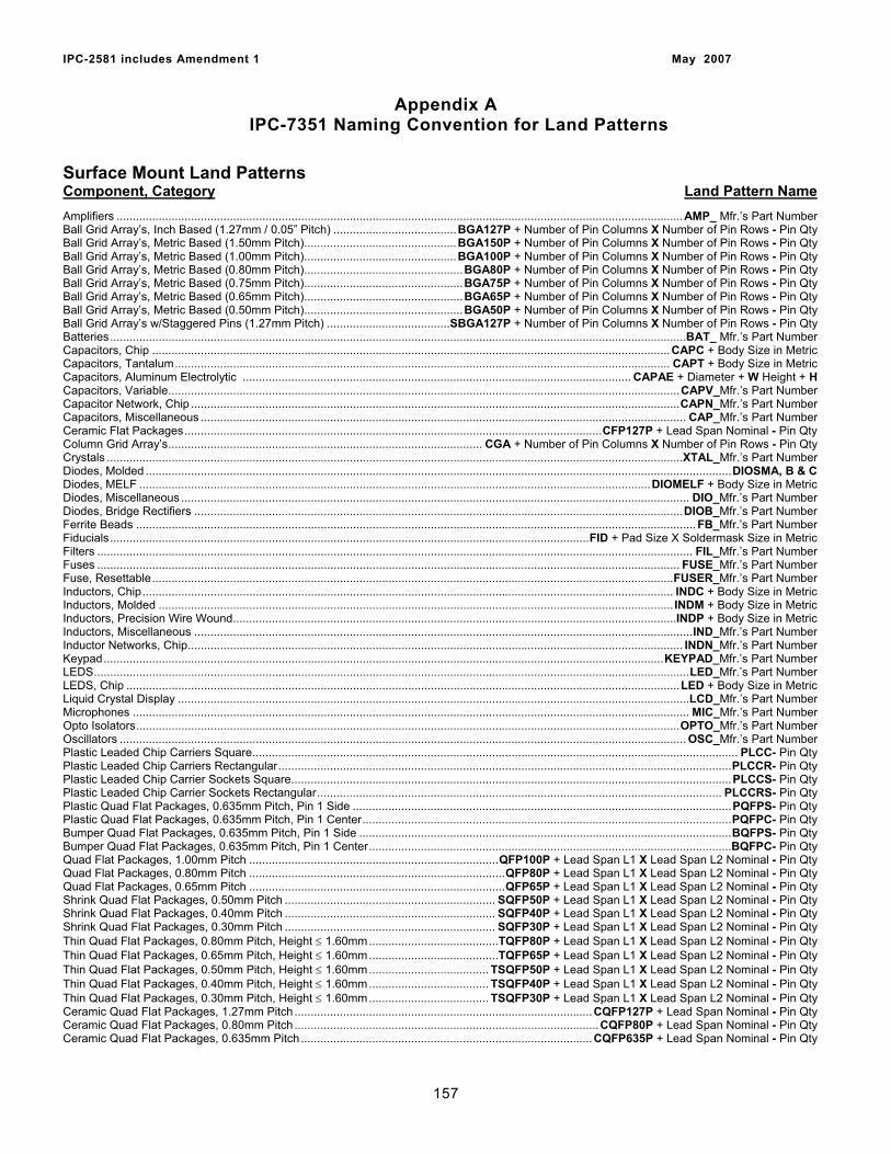
IPC-2581 includes Amendment 1 May 2007
Appendix A IPC-7351 Naming Convention for Land Patterns
Surface Mount Land Patterns Component, Category Land Pattern Name Amplifiers ...............................................................................................................................................................................AMP_ Mfr.’s Part Number Ball Grid Array’s, Inch Based (1.27mm / 0.05” Pitch) ......................................BGA127P + Number of Pin Columns X Number of Pin Rows - Pin Qty Ball Grid Array’s, Metric Based (1.50mm Pitch)...............................................BGA150P + Number of Pin Columns X Number of Pin Rows - Pin Qty Ball Grid Array’s, Metric Based (1.00mm Pitch)...............................................BGA100P + Number of Pin Columns X Number of Pin Rows - Pin Qty Ball Grid Array’s, Metric Based (0.80mm Pitch).................................................BGA80P + Number of Pin Columns X Number of Pin Rows - Pin Qty Ball Grid Array’s, Metric Based (0.75mm Pitch).................................................BGA75P + Number of Pin Columns X Number of Pin Rows - Pin Qty Ball Grid Array’s, Metric Based (0.65mm Pitch).................................................BGA65P + Number of Pin Columns X Number of Pin Rows - Pin Qty Ball Grid Array’s, Metric Based (0.50mm Pitch).................................................BGA50P + Number of Pin Columns X Number of Pin Rows - Pin Qty Ball Grid Array’s w/Staggered Pins (1.27mm Pitch) ......................................SBGA127P + Number of Pin Columns X Number of Pin Rows - Pin Qty Batteries..................................................................................................................................................................................BAT_ Mfr.’s Part Number Capacitors, Chip ................................................................................................................................................................CAPC + Body Size in Metric Capacitors, Tantalum......................................................................................................................................................... CAPT + Body Size in Metric Capacitors, Aluminum Electrolytic ........................................................................................................................ CAPAE + Diameter + W Height + H Capacitors, Variable..............................................................................................................................................................CAPV_Mfr.’s Part Number Capacitor Network, Chip .......................................................................................................................................................CAPN_Mfr.’s Part Number Capacitors, Miscellaneous ...................................................................................................................................................... CAP_Mfr.’s Part Number Ceramic Flat Packages.................................................................................................................................CFP127P + Lead Span Nominal - Pin Qty Column Grid Array’s................................................................................................. CGA + Number of Pin Columns X Number of Pin Rows - Pin Qty Crystals ..................................................................................................................................................................................XTAL_Mfr.’s Part Number Diodes, Molded .....................................................................................................................................................................................DIOSMA, B & C Diodes, MELF ..............................................................................................................................................................DIOMELF + Body Size in Metric Diodes, Miscellaneous ............................................................................................................................................................. DIO_Mfr.’s Part Number Diodes, Bridge Rectifiers .......................................................................................................................................................DIOB_Mfr.’s Part Number Ferrite Beads ............................................................................................................................................................................. FB_Mfr.’s Part Number Fiducials....................................................................................................................................................FID + Pad Size X Soldermask Size in Metric Filters ........................................................................................................................................................................................ FIL_Mfr.’s Part Number Fuses .................................................................................................................................................................................... FUSE_Mfr.’s Part Number Fuse, Resettable.................................................................................................................................................................FUSER_Mfr.’s Part Number Inductors, Chip.................................................................................................................................................................... INDC + Body Size in Metric Inductors, Molded ............................................................................................................................................................... INDM + Body Size in Metric Inductors, Precision Wire Wound.........................................................................................................................................INDP + Body Size in Metric Inductors, Miscellaneous ..........................................................................................................................................................IND_Mfr.’s Part Number Inductor Networks, Chip......................................................................................................................................................... INDN_Mfr.’s Part Number Keypad.............................................................................................................................................................................KEYPAD_Mfr.’s Part Number LEDS........................................................................................................................................................................................LED_Mfr.’s Part Number LEDS, Chip ...........................................................................................................................................................................LED + Body Size in Metric Liquid Crystal Display ..............................................................................................................................................................LCD_Mfr.’s Part Number Microphones ............................................................................................................................................................................ MIC_Mfr.’s Part Number Opto Isolators........................................................................................................................................................................OPTO_Mfr.’s Part Number Oscillators ............................................................................................................................................................................... OSC_Mfr.’s Part Number Plastic Leaded Chip Carriers Square...................................................................................................................................................... PLCC- Pin Qty Plastic Leaded Chip Carriers Rectangular............................................................................................................................................PLCCR- Pin Qty Plastic Leaded Chip Carrier Sockets Square........................................................................................................................................PLCCS- Pin Qty Plastic Leaded Chip Carrier Sockets Rectangular............................................................................................................................. PLCCRS- Pin Qty Plastic Quad Flat Packages, 0.635mm Pitch, Pin 1 Side .....................................................................................................................PQFPS- Pin Qty Plastic Quad Flat Packages, 0.635mm Pitch, Pin 1 Center..................................................................................................................PQFPC- Pin Qty Bumper Quad Flat Packages, 0.635mm Pitch, Pin 1 Side ...................................................................................................................BQFPS- Pin Qty Bumper Quad Flat Packages, 0.635mm Pitch, Pin 1 Center................................................................................................................BQFPC- Pin Qty Quad Flat Packages, 1.00mm Pitch .............................................................................QFP100P + Lead Span L1 X Lead Span L2 Nominal - Pin Qty Quad Flat Packages, 0.80mm Pitch ...............................................................................QFP80P + Lead Span L1 X Lead Span L2 Nominal - Pin Qty Quad Flat Packages, 0.65mm Pitch ...............................................................................QFP65P + Lead Span L1 X Lead Span L2 Nominal - Pin Qty Shrink Quad Flat Packages, 0.50mm Pitch ................................................................. SQFP50P + Lead Span L1 X Lead Span L2 Nominal - Pin Qty Shrink Quad Flat Packages, 0.40mm Pitch ................................................................. SQFP40P + Lead Span L1 X Lead Span L2 Nominal - Pin Qty Shrink Quad Flat Packages, 0.30mm Pitch ................................................................. SQFP30P + Lead Span L1 X Lead Span L2 Nominal - Pin Qty Thin Quad Flat Packages, 0.80mm Pitch, Height ≤ 1.60mm........................................TQFP80P + Lead Span L1 X Lead Span L2 Nominal - Pin Qty Thin Quad Flat Packages, 0.65mm Pitch, Height ≤ 1.60mm........................................TQFP65P + Lead Span L1 X Lead Span L2 Nominal - Pin Qty Thin Quad Flat Packages, 0.50mm Pitch, Height ≤ 1.60mm..................................... TSQFP50P + Lead Span L1 X Lead Span L2 Nominal - Pin Qty Thin Quad Flat Packages, 0.40mm Pitch, Height ≤ 1.60mm..................................... TSQFP40P + Lead Span L1 X Lead Span L2 Nominal - Pin Qty Thin Quad Flat Packages, 0.30mm Pitch, Height ≤ 1.60mm..................................... TSQFP30P + Lead Span L1 X Lead Span L2 Nominal - Pin Qty Ceramic Quad Flat Packages, 1.27mm Pitch ............................................................................................CQFP127P + Lead Span Nominal - Pin Qty Ceramic Quad Flat Packages, 0.80mm Pitch ..............................................................................................CQFP80P + Lead Span Nominal - Pin Qty Ceramic Quad Flat Packages, 0.635mm Pitch ..........................................................................................CQFP635P + Lead Span Nominal - Pin Qty
157
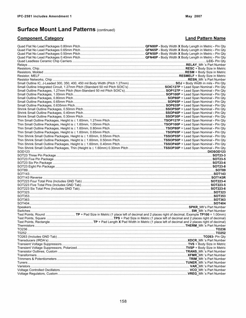
IPC-2581 includes Amendment 1 May 2007
Surface Mount Land Patterns (continued)
Component, Category Land Pattern Name Quad Flat No Lead Packages 0.80mm Pitch........................................................................ QFN80P - Body Width X Body Length in Metric - Pin Qty Quad Flat No Lead Packages 0.65mm Pitch........................................................................ QFN65P - Body Width X Body Length in Metric - Pin Qty Quad Flat No Lead Packages 0.50mm Pitch........................................................................ QFN50P - Body Width X Body Length in Metric - Pin Qty Quad Flat No Lead Packages 0.40mm Pitch........................................................................ QFN40P - Body Width X Body Length in Metric - Pin Qty Quad Leadless Ceramic Chip Carriers ......................................................................................................................................................LCC- Pin Qty Relays .................................................................................................................................................................................RELAY_Mfr.’s Part Number Resistors, Chip................................................................................................................................................................... RESC + Body Size in Metric Resistors, Molded ..............................................................................................................................................................RESM + Body Size in Metric Resistor, MELF ...........................................................................................................................................................RESMELF + Body Size in Metric Resistor Networks, Chip .......................................................................................................................................................RESN_Mfr.’s Part Number Small Outline IC, J-Leaded 300, 350, 400, 450 mil Body Width (Pitch 1.27mm) ................................................... SOJ + Body Width in mils - Pin Qty Small Outline Integrated Circuit, 1.27mm Pitch (Standard 50 mil Pitch SOIC’s) ........................................ SOIC127P + Lead Span Nominal - Pin Qty Small Outline Packages, 1.27mm Pitch (Non-Standard 50 mil Pitch SOIC’s) ............................................. SOP127P + Lead Span Nominal - Pin Qty Small Outline Packages, 1.00mm Pitch....................................................................................................... SOP100P + Lead Span Nominal - Pin Qty Small Outline Packages, 0.80mm Pitch......................................................................................................... SOP80P + Lead Span Nominal - Pin Qty Small Outline Packages, 0.65mm Pitch......................................................................................................... SOP65P + Lead Span Nominal - Pin Qty Small Outline Packages, 0.635mm Pitch..................................................................................................... SOP635P + Lead Span Nominal - Pin Qty Shrink Small Outline Packages, 0.50mm Pitch............................................................................................SSOP50P + Lead Span Nominal - Pin Qty Shrink Small Outline Packages, 0.40mm Pitch............................................................................................SSOP40P + Lead Span Nominal - Pin Qty Shrink Small Outline Packages, 0.30mm Pitch............................................................................................SSOP30P + Lead Span Nominal - Pin Qty Thin Small Outline Packages, Height is ≤ 1.60mm, 1.27mm Pitch............................................................ TSOP127P + Lead Span Nominal - Pin Qty Thin Small Outline Packages, Height is ≤ 1.60mm, 1.00mm Pitch............................................................ TSOP100P + Lead Span Nominal - Pin Qty Thin Small Outline Packages, Height is ≤ 1.60mm, 0.80mm Pitch.............................................................. TSOP80P + Lead Span Nominal - Pin Qty Thin Small Outline Packages, Height is ≤ 1.60mm, 0.65mm Pitch.............................................................. TSOP65P + Lead Span Nominal - Pin Qty Thin Shrink Small Outline Packages, Height is ≤ 1.60mm, 0.55mm Pitch.................................................TSSOP55P + Lead Span Nominal - Pin Qty Thin Shrink Small Outline Packages, Height is ≤ 1.60mm, 0.50mm Pitch.................................................TSSOP50P + Lead Span Nominal - Pin Qty Thin Shrink Small Outline Packages, Height is ≤ 1.60mm, 0.40mm Pitch.................................................TSSOP40P + Lead Span Nominal - Pin Qty Thin Shrink Small Outline Packages, Thin (Height is ≤ 1.60mm) 0.30mm Pitch .......................................TSSOP30P + Lead Span Nominal - Pin Qty SOD123 ......................................................................................................................................................................................................DIOSOD123 SOT23 Three Pin Package .............................................................................................................................................................................. SOT23-3 SOT23 Five Pin Package................................................................................................................................................................................. SOT23-5 SOT23 Six Pin Package .................................................................................................................................................................................. SOT23-6 SOT23 Eight Pin Package ............................................................................................................................................................................... SOT23-8 SOT89..................................................................................................................................................................................................................SOT89 SOT143..............................................................................................................................................................................................................SOT143 SOT143 Reverse ............................................................................................................................................................................................ SOT143R SOT223 Four Total Pins (Includes GND Tab) ............................................................................................................................................... SOT223-4 SOT223 Five Total Pins (Includes GND Tab)................................................................................................................................................ SOT223-5 SOT223 Six Total Pins (Includes GND Tab).................................................................................................................................................. SOT223-6 SOT323..............................................................................................................................................................................................................SOT323 SOT353..............................................................................................................................................................................................................SOT353 SOT363..............................................................................................................................................................................................................SOT363 SOT404..............................................................................................................................................................................................................SOT404 Speakers................................................................................................................................................................................SPKR_Mfr’s Part Number Switches.................................................................................................................................................................................... SW_Mfr.’s Part Number Test Points, Round ................................. TP + Pad Size in Metric (1 place left of decimal and 2 places right of decimal, Example TP100 = 1.00mm) Test Points, Square ...........................................................................TPS + Pad Size in Metric (1 place left of decimal and 2 places right of decimal) Test Points, Rectangle................................................ TP + Pad Length X Pad Width in Metric (1 place left of decimal and 2 places right of decimal) Thermistors ........................................................................................................................................................................THERM_Mfr.’s Part Number TO236 .................................................................................................................................................................................................................. TO236 T0252................................................................................................................................................................................................................... TO252 TO263 (Includes GND Tab) ................................................................................................................................................................... TO263- Pin Qty Transducers (IRDA’s) ...........................................................................................................................................................XDCR_Mfr.’s Part Number Transient Voltage Suppressors............................................................................................................................................. TVS + Body Size in Metric Transient Voltage Suppressors, Polarized..........................................................................................................................TVSP + Body Size in Metric Transistor Outlines, Custom .............................................................................................................................................. TRANS_Mfr.’s Part Number Transformers.........................................................................................................................................................................XFMR_Mfr.’s Part Number Trimmers & Potentiometers ................................................................................................................................................... TRIM_Mfr.’s Part Number Tuners................................................................................................................................................................................ TUNER_Mfr.’s Part Number Varistors.................................................................................................................................................................................. VAR_Mfr.’s Part Number Voltage Controlled Oscillators................................................................................................................................................. VCO_Mfr.’s Part Number Voltage Regulators, Custom.................................................................................................................................................VREG_Mfr.’s Part Number
158
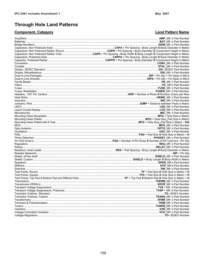
IPC-2581 includes Amendment 1 May 2007
Through Hole Land Patterns
Component, Category Land Pattern Name Amplifiers ................................................................................................................................................................................ AMP_Mfr.’s Part Number Batteries...................................................................................................................................................................................BAT_Mfr.’s Part Number Bridge Rectifiers..................................................................................................................................................................... DIOB_Mfr.’s Part Number Capacitors, Non Polarized Axial ..................................................................................CAPA + Pin Spacing - Body Length X Body Diameter in Metric Capacitors, Non Polarized Radial, Round .........................................................CAPR + Pin Spacing - Body Diameter X Component Height in Metric Capacitors, Non Polarized Radial, Oval..........................................CAPR + Pin Spacing - Body Width X Body Length X Component Height in Metric Capacitors, Polarized Axial ....................................................................................... CAPPA + Pin Spacing - Body Length X Body Diameter in Metric Capacitor, Polarized Radial ............................................................................ CAPPR + Pin Spacing - Body Diameter X Component Height in Metric Converters ............................................................................................................................................................................CONV_Mfr.’s Part Number Crystals ..................................................................................................................................................................................XTAL_Mfr.’s Part Number Diodes, JEDEC Standard .......................................................................................................................................................DO- JEDEC Part Number Diodes, Miscellaneous ..............................................................................................................................................................DIO_Mfr.’s Part Number Dual-In-Line Packages...............................................................................................................................................DIP + Pin Qty + Pin Span in MILS Dual-In-Line Sockets............................................................................................................................................... DIPS + Pin Qty + Pin Span in MILS Ferrite Beads ............................................................................................................................................................................. FB_Mfr.’s Part Number Filters ..........................................................................................................................................................................................FIL_Mfr’s Part Number Fuses .....................................................................................................................................................................................FUSE_Mfr.’s Part Number Fuses, Resettable ...............................................................................................................................................................FUSER_Mfr.’s Part Number Headers, .100” Pin Centers ...........................................................................................................HDR + Number of Rows X Number of pins per Row Heat Sinks............................................................................................................................................................................ HSINK_Mfr.’s Part Number Inductors ................................................................................................................................................................................... IND_Mfr.’s Part Number Jumpers, Wire...............................................................................................................................................JUMP + Distance between Pads in Metric LED’s ....................................................................................................................................................................................... LED_Mfr.’s Part Number Liquid Crystal Display ..............................................................................................................................................................LCD_Mfr.’s Part Number Microphones .............................................................................................................................................................................MIC_Mfr.’s Part Number Mounting Holes Nonplated.................................................................................................................................................... MTG + Hole Size in Metric Mounting Holes Plated..........................................................................................................................................MTG + Hole Size_Pad Size in Metric Mounting Holes Plated with 8 Vias .............................................................................................................MTG + Hole Size_Pad Size in Metric - VIA MOV........................................................................................................................................................................................ MOV_Mfr.’s Part Number Opto Isolators........................................................................................................................................................................ OPTO_Mfr.’s Part Number Oscillators ............................................................................................................................................................................... OSC_Mfr.’s Part Number PAD.............................................................................................................................................................. PAD + Pad Size X Hole Size in Metric + H Photo Detectors ............................................................................................................................................................... PHODET_Mfr.’s Part Number Pin Grid Array’s.........................................................................................................PGA + Number of Pin Rows X Number of Pin Columns - Pin Qty Regulators............................................................................................................................................................................... REG_Mfr.’s Part Number Relays ................................................................................................................................................................................. RELAY_Mfr.’s Part Number Resistors, Axial Leads .................................................................................................. RES + Pad Spacing - Body Length X Body Diameter in Metric Resistor Networks......................................................................................................................................................................................SIP + Pin Qty Shield, off the shelf ............................................................................................................................................................ SHIELD_Mfr.’s Part Number Shield, Custom..................................................................................................................................... SHIELD + Body Length X Body Width in Metric Speakers................................................................................................................................................................................ SPKR_Mfr’s Part Number Stiffners.................................................................................................................................................................................... STIF_Mfr’s Part Number Switches.................................................................................................................................................................................... SW_Mfr.’s Part Number Test Points, Round ......................................................................................................................................... TP + Pad Size X Hole Size in Metric + H Test Points, Square ......................................................................................................................................TPS + Pad Size X Hole Size in Metric + H Test Points, Top Pad & Bottom Pad are Different Size ............................................................TP + Top Pad X Bottom Pad X Hole Size in Metric + H Thermistors ........................................................................................................................................................................ THERM_Mfr.’s Part Number Transducers (IRDA’s) ........................................................................................................................................................... XDCR_Mfr.’s Part Number Transient Voltage Suppressors..............................................................................................................................................TVS + Mfr.’s Part Number Transient Voltage Suppressors, Polarized.......................................................................................................................... TVSP + Mfr.’s Part Number Transistor Outlines, Standard ........................................................................................................................................................ TO- JEDEC Number Transistor Outlines, Custom ...............................................................................................................................................TRANS_Mfr.’s Part Number Transformers......................................................................................................................................................................... XFMR_Mfr.’s Part Number Trimmers & Potentiometers ................................................................................................................................................... TRIM_Mfr.’s Part Number Tuners.................................................................................................................................................................................TUNER_Mfr.’s Part Number Varistors...................................................................................................................................................................................VAR_Mfr.’s Part Number Voltage Controlled Oscillator .................................................................................................................................................. VCO_Mfr.’s Part Number Voltage Regulators .........................................................................................................................................................................TO- JEDEC Number
159
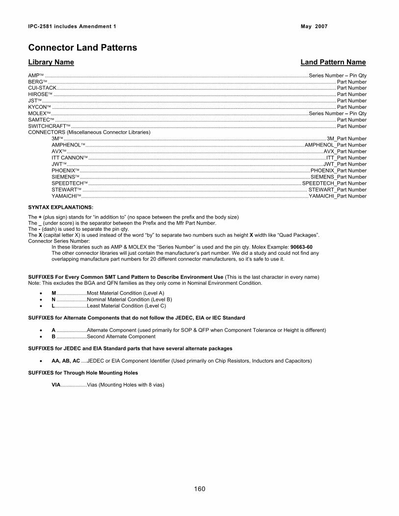
IPC-2581 includes Amendment 1 May 2007
Connector Land Patterns Library Name Land Pattern Name AMP™ ......................................................................................................................................................................................Series Number – Pin Qty BERG™ ....................................................................................................................................................................................................... Part Number CUI-STACK................................................................................................................................................................................................. Part Number HIROSE™ ................................................................................................................................................................................................... Part Number JST™........................................................................................................................................................................................................... Part Number KYCON™ .................................................................................................................................................................................................... Part Number MOLEX™..................................................................................................................................................................................Series Number – Pin Qty SAMTEC™ .................................................................................................................................................................................................. Part Number SWITCHCRAFT™ ....................................................................................................................................................................................... Part Number CONNECTORS (Miscellaneous Connector Libraries)
3M™ ..................................................................................................................................................................................... 3M_Part Number AMPHENOL™.......................................................................................................................................................AMPHENOL_Part Number AVX™.................................................................................................................................................................................AVX_Part Number ITT CANNON™ ....................................................................................................................................................................ITT_Part Number JWT™.................................................................................................................................................................................JWT_Part Number PHOENIX™...............................................................................................................................................................PHOENIX_Part Number SIEMENS™...............................................................................................................................................................SIEMENS_Part Number SPEEDTECH™ ................................................................................................................................................... SPEEDTECH_Part Number STEWART™ ........................................................................................................................................................... STEWART_Part Number YAMAICHI™.............................................................................................................................................................YAMAICHI_Part Number
SYNTAX EXPLANATIONS:
The + (plus sign) stands for “in addition to” (no space between the prefix and the body size) The _ (under score) is the separator between the Prefix and the Mfr Part Number. The - (dash) is used to separate the pin qty. The X (capital letter X) is used instead of the word “by” to separate two numbers such as height X width like “Quad Packages”. Connector Series Number: In these libraries such as AMP & MOLEX the “Series Number” is used and the pin qty. Molex Example: 90663-60
The other connector libraries will just contain the manufacturer’s part number. We did a study and could not find any overlapping manufacture part numbers for 20 different connector manufacturers, so it’s safe to use it.
SUFFIXES For Every Common SMT Land Pattern to Describe Environment Use (This is the last character in every name) Note: This excludes the BGA and QFN families as they only come in Nominal Environment Condition.
• M .....................Most Material Condition (Level A) • N .....................Nominal Material Condition (Level B) • L......................Least Material Condition (Level C)
SUFFIXES for Alternate Components that do not follow the JEDEC, EIA or IEC Standard
• A .....................Alternate Component (used primarily for SOP & QFP when Component Tolerance or Height is different) • B .....................Second Alternate Component
SUFFIXES for JEDEC and EIA Standard parts that have several alternate packages
• AA, AB, AC ....JEDEC or EIA Component Identifier (Used primarily on Chip Resistors, Inductors and Capacitors) SUFFIXES for Through Hole Mounting Holes
VIA..................Vias (Mounting Holes with 8 vias)
160
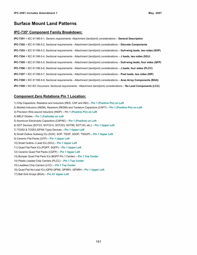
IPC-2581 includes Amendment 1 May 2007
Surface Mount Land Patterns IPC-735* Component Family Breakdown: IPC-7351 = IEC 61188-5-1, Generic requirements- Attachment (land/joint) considerations – General Description IPC-7352 = IEC 61188-5-2, Sectional requirements - Attachment (land/joint) considerations – Discrete Components IPC-7353 = IEC 61188-5-3, Sectional requirements - Attachment (land/joint) considerations – Gull-wing leads, two sides (SOP) IPC-7354 = IEC 61188-5-4, Sectional requirements - Attachment (land/joint) considerations – J leads, two sides (SOJ) IPC-7355 = IEC 61188-5-5, Sectional requirements - Attachment (land/joint) considerations – Gull-wing leads, four sides (QFP) IPC-7356 = IEC 61188-5-6, Sectional requirements - Attachment (land/joint) considerations – J leads, four sides (PLCC) IPC-7357 = IEC 61188-5-7, Sectional requirements - Attachment (land/joint) considerations – Post leads, two sides (DIP) IPC-7358 = IEC 61188-5-8, Sectional requirements - Attachment (land/joint) considerations – Area Array Components (BGA) IPC-7359 = NO IEC Document, Sectional requirements - Attachment (land/joint) considerations – No Lead Components (LCC) Component Zero Rotations Pin 1 Location: 1) Chip Capacitors, Resistors and Inductors (RES, CAP and IND) – Pin 1 (Positive Pin) on Left 2) Molded Inductors (INDM), Resistors (RESM) and Tantalum Capacitors (CAPT) – Pin 1 (Positive Pin) on Left 3) Precision Wire-wound Inductors (INDP) – Pin 1 (Positive Pin) on Left 4) MELF Diodes – Pin 1 (Cathode) on Left 5) Aluminum Electrolytic Capacitors (CAPAE) – Pin 1 (Positive) on Left 6) SOT Devices (SOT23, SOT23-5, SOT223, SOT89, SOT143, etc.) – Pin 1 Upper Left 7) TO252 & TO263 (DPAK Type) Devices – Pin 1 Upper Left 8) Small Outline Gullwing ICs (SOIC, SOP, TSOP, SSOP, TSSOP) – Pin 1 Upper Left 9) Ceramic Flat Packs (CFP) – Pin 1 Upper Left 10) Small Outline J Lead ICs (SOJ) – Pin 1 Upper Left 11) Quad Flat Pack ICs (PQFP, SQFP) – Pin 1 Upper Left 12) Ceramic Quad Flat Packs (CQFP) – Pin 1 Upper Left 13) Bumper Quad Flat Pack ICs (BQFP Pin 1 Center) – Pin 1 Top Center 14) Plastic Leaded Chip Carriers (PLCC) – Pin 1 Top Center 15) Leadless Chip Carriers (LCC) – Pin 1 Top Center 16) Quad Flat No-Lead ICs (QFN) QFNS, QFNRV, QFNRH – Pin 1 Upper Left
17) Ball Grid Arrays (BGA) – Pin A1 Upper Left
161
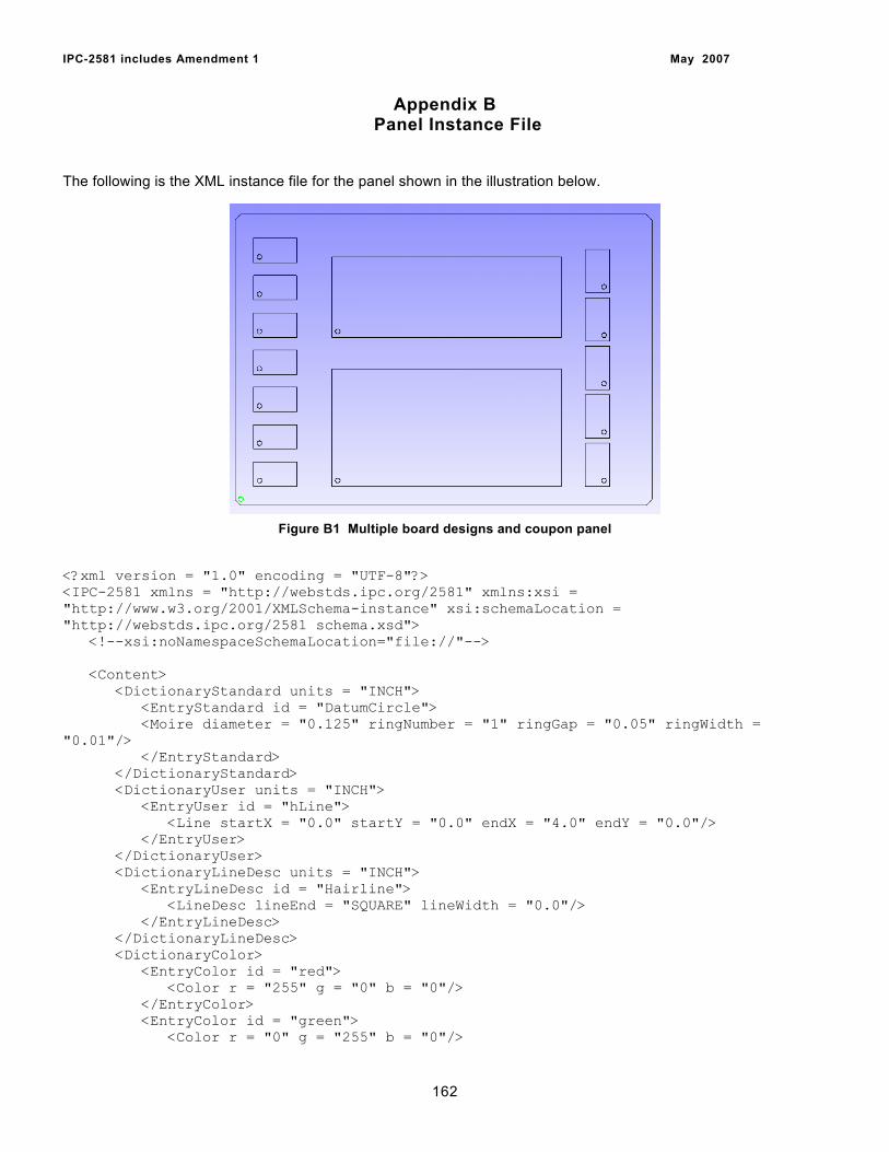
IPC-2581 includes Amendment 1 May 2007
Appendix B Panel Instance File
The following is the XML instance file for the panel shown in the illustration below.
Figure B1 Multiple board designs and coupon panel
<?xml version = "1.0" encoding = "UTF-8"?> <IPC-2581 xmlns = "http://webstds.ipc.org/2581" xmlns:xsi = "http://www.w3.org/2001/XMLSchema-instance" xsi:schemaLocation = "http://webstds.ipc.org/2581 schema.xsd"> <!--xsi:noNamespaceSchemaLocation="file://"--> <Content> <DictionaryStandard units = "INCH"> <EntryStandard id = "DatumCircle"> <Moire diameter = "0.125" ringNumber = "1" ringGap = "0.05" ringWidth = "0.01"/> </EntryStandard> </DictionaryStandard> <DictionaryUser units = "INCH"> <EntryUser id = "hLine"> <Line startX = "0.0" startY = "0.0" endX = "4.0" endY = "0.0"/> </EntryUser> </DictionaryUser> <DictionaryLineDesc units = "INCH"> <EntryLineDesc id = "Hairline"> <LineDesc lineEnd = "SQUARE" lineWidth = "0.0"/> </EntryLineDesc> </DictionaryLineDesc> <DictionaryColor> <EntryColor id = "red"> <Color r = "255" g = "0" b = "0"/> </EntryColor> <EntryColor id = "green"> <Color r = "0" g = "255" b = "0"/>
162
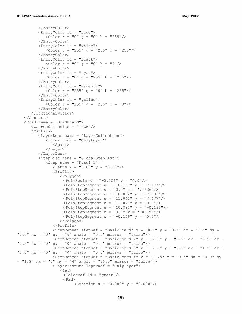
IPC-2581 includes Amendment 1 May 2007
</EntryColor> <EntryColor id = "blue"> <Color r = "0" g = "0" b = "255"/> </EntryColor> <EntryColor id = "white"> <Color r = "255" g = "255" b = "255"/> </EntryColor> <EntryColor id = "black"> <Color r = "0" g = "0" b = "0"/> </EntryColor> <EntryColor id = "cyan"> <Color r = "0" g = "255" b = "255"/> </EntryColor> <EntryColor id = "magenta"> <Color r = "255" g = "0" b = "255"/> </EntryColor> <EntryColor id = "yellow"> <Color r = "255" g = "255" b = "0"/> </EntryColor> </DictionaryColor> </Content> <Ecad name = "GridBoard"> <CadHeader units = "INCH"/> <CadData> <LayerDesc name = "LayerCollection"> <Layer name = "OnlyLayer"> <Span/> </Layer> </LayerDesc> <StepList name = "GlobalStepList"> <Step name = "Panel_1"> <Datum x = "0.00" y = "0.00"/> <Profile> <Polygon> <PolyBegin x = "-0.159" y = "0.0"/> <PolyStepSegment x = "-0.159" y = "7.477"/> <PolyStepSegment x = "0.0" y = "7.636"/> <PolyStepSegment x = "10.882" y = "7.636"/> <PolyStepSegment x = "11.041" y = "7.477"/> <PolyStepSegment x = "11.041" y = "0.0"/> <PolyStepSegment x = "10.882" y = "-0.159"/> <PolyStepSegment x = "0.0" y = "-0.159"/> <PolyStepSegment x = "-0.159" y = "0.0"/> </Polygon> </Profile> <StepRepeat stepRef = "BasicBoard" x = "0.5" y = "0.5" dx = "1.5" dy = "1.0" nx = "0" ny = "6" angle = "0.0" mirror = "false"/> <StepRepeat stepRef = "BasicBoard_2" x = "2.6" y = "0.5" dx = "0.9" dy = "1.3" nx = "0" ny = "0" angle = "0.0" mirror = "false"/> <StepRepeat stepRef = "BasicBoard_3" x = "2.6" y = "4.5" dx = "1.5" dy = "1.0" nx = "0" ny = "0" angle = "0.0" mirror = "false"/> <StepRepeat stepRef = "BasicBoard_4" x = "9.75" y = "0.5" dx = "0.9" dy = "1.3" nx = "0" ny = "4" angle = "90.0" mirror = "false"/> <LayerFeature layerRef = "OnlyLayer"> <Set> <ColorRef id = "green"/> <Pad> <Location x = "0.000" y = "0.000"/>
163
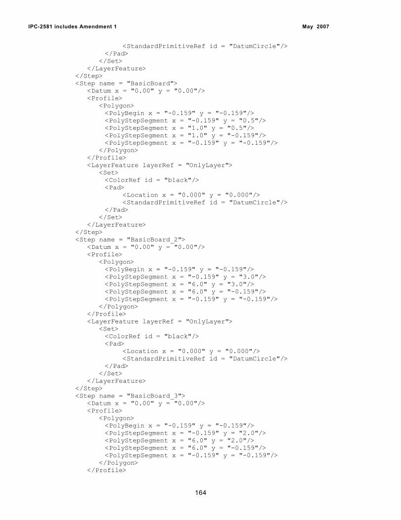
IPC-2581 includes Amendment 1 May 2007
<StandardPrimitiveRef id = "DatumCircle"/> </Pad> </Set> </LayerFeature> </Step> <Step name = "BasicBoard"> <Datum x = "0.00" y = "0.00"/> <Profile> <Polygon> <PolyBegin x = "-0.159" y = "-0.159"/> <PolyStepSegment x = "-0.159" y = "0.5"/> <PolyStepSegment x = "1.0" y = "0.5"/> <PolyStepSegment x = "1.0" y = "-0.159"/> <PolyStepSegment x = "-0.159" y = "-0.159"/> </Polygon> </Profile> <LayerFeature layerRef = "OnlyLayer"> <Set> <ColorRef id = "black"/> <Pad> <Location x = "0.000" y = "0.000"/> <StandardPrimitiveRef id = "DatumCircle"/> </Pad> </Set> </LayerFeature> </Step> <Step name = "BasicBoard_2"> <Datum x = "0.00" y = "0.00"/> <Profile> <Polygon> <PolyBegin x = "-0.159" y = "-0.159"/> <PolyStepSegment x = "-0.159" y = "3.0"/> <PolyStepSegment x = "6.0" y = "3.0"/> <PolyStepSegment x = "6.0" y = "-0.159"/> <PolyStepSegment x = "-0.159" y = "-0.159"/> </Polygon> </Profile> <LayerFeature layerRef = "OnlyLayer"> <Set> <ColorRef id = "black"/> <Pad> <Location x = "0.000" y = "0.000"/> <StandardPrimitiveRef id = "DatumCircle"/> </Pad> </Set> </LayerFeature> </Step> <Step name = "BasicBoard_3"> <Datum x = "0.00" y = "0.00"/> <Profile> <Polygon> <PolyBegin x = "-0.159" y = "-0.159"/> <PolyStepSegment x = "-0.159" y = "2.0"/> <PolyStepSegment x = "6.0" y = "2.0"/> <PolyStepSegment x = "6.0" y = "-0.159"/> <PolyStepSegment x = "-0.159" y = "-0.159"/> </Polygon> </Profile>
164
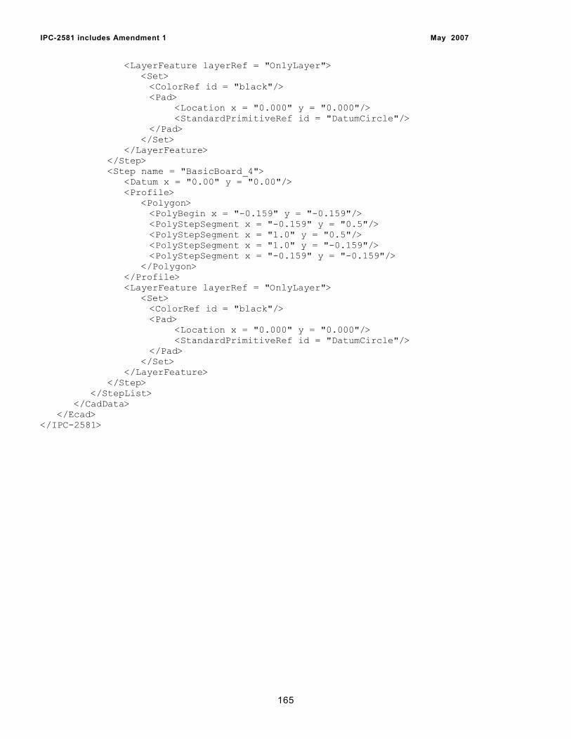
IPC-2581 includes Amendment 1 May 2007
<LayerFeature layerRef = "OnlyLayer"> <Set> <ColorRef id = "black"/> <Pad> <Location x = "0.000" y = "0.000"/> <StandardPrimitiveRef id = "DatumCircle"/> </Pad> </Set> </LayerFeature> </Step> <Step name = "BasicBoard_4"> <Datum x = "0.00" y = "0.00"/> <Profile> <Polygon> <PolyBegin x = "-0.159" y = "-0.159"/> <PolyStepSegment x = "-0.159" y = "0.5"/> <PolyStepSegment x = "1.0" y = "0.5"/> <PolyStepSegment x = "1.0" y = "-0.159"/> <PolyStepSegment x = "-0.159" y = "-0.159"/> </Polygon> </Profile> <LayerFeature layerRef = "OnlyLayer"> <Set> <ColorRef id = "black"/> <Pad> <Location x = "0.000" y = "0.000"/> <StandardPrimitiveRef id = "DatumCircle"/> </Pad> </Set> </LayerFeature> </Step> </StepList> </CadData> </Ecad> </IPC-2581>
165