Embed Size (px)
Citation preview
IPv6 Static Routes
Overview
Overview of IPv6 Static Routes 2© 2007 – 2010, Cisco Systems, Inc. All rights reserved. Cisco Public
Overview of IPv6 Static Routes 3© 2007 – 2010, Cisco Systems, Inc. All rights reserved. Cisco Public
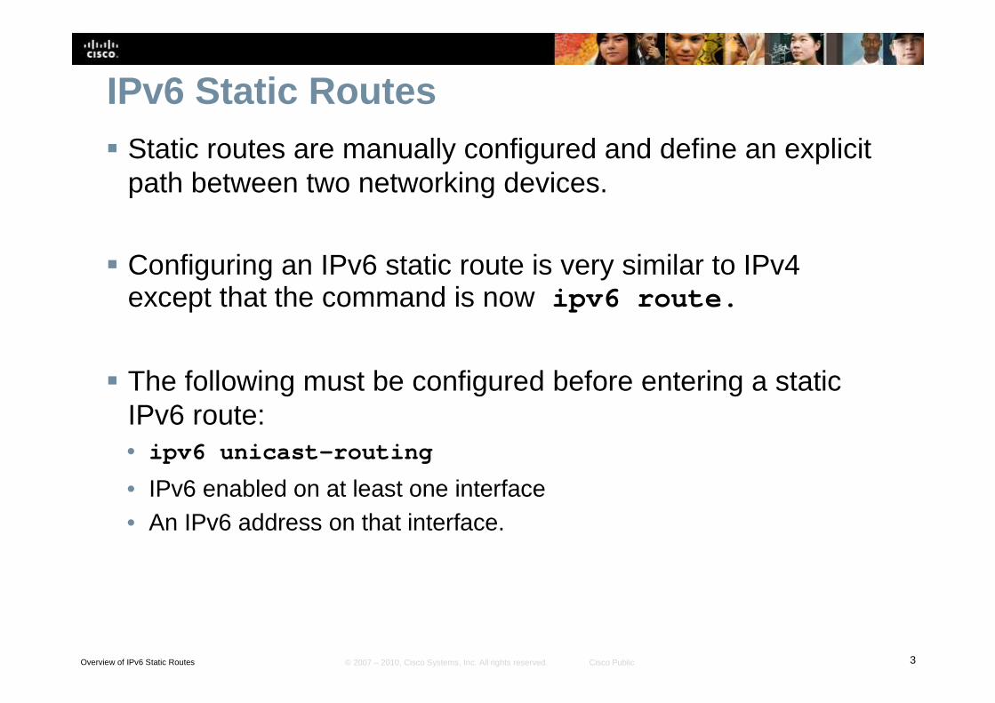
IPv6 Static Routes� Static routes are manually configured and define an explicit
path between two networking devices.
� Configuring an IPv6 static route is very similar to IPv4 except that the command is now ipv6 route.
� The following must be configured before entering a static IPv6 route:• ipv6 unicast-routing
• IPv6 enabled on at least one interface• An IPv6 address on that interface.
Overview of IPv6 Static Routes 4© 2007 – 2010, Cisco Systems, Inc. All rights reserved. Cisco Public
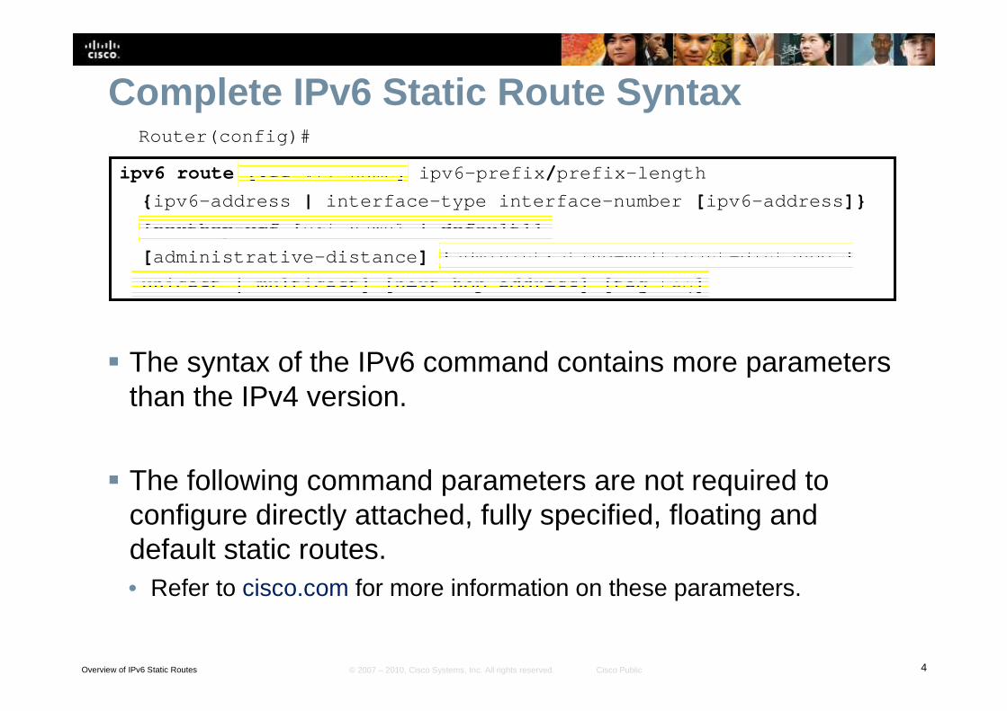
Complete IPv6 Static Route SyntaxRouter(config)#
ipv6 route [vrf vrf-name] ipv6-prefix/prefix-length
{ipv6-address | interface-type interface-number [ipv6-address]}
[nexthop-vrf [vrf-name1 | default]]
[administrative-distance] [administrative-multicast-distance |
unicast | multicast] [next-hop-address] [tag tag]
� The syntax of the IPv6 command contains more parameters than the IPv4 version.
� The following command parameters are not required to configure directly attached, fully specified, floating and default static routes.• Refer to cisco.com for more information on these parameters.
Overview of IPv6 Static Routes 5© 2007 – 2010, Cisco Systems, Inc. All rights reserved. Cisco Public
Overview of IPv6 Static Routes 6© 2007 – 2010, Cisco Systems, Inc. All rights reserved. Cisco Public
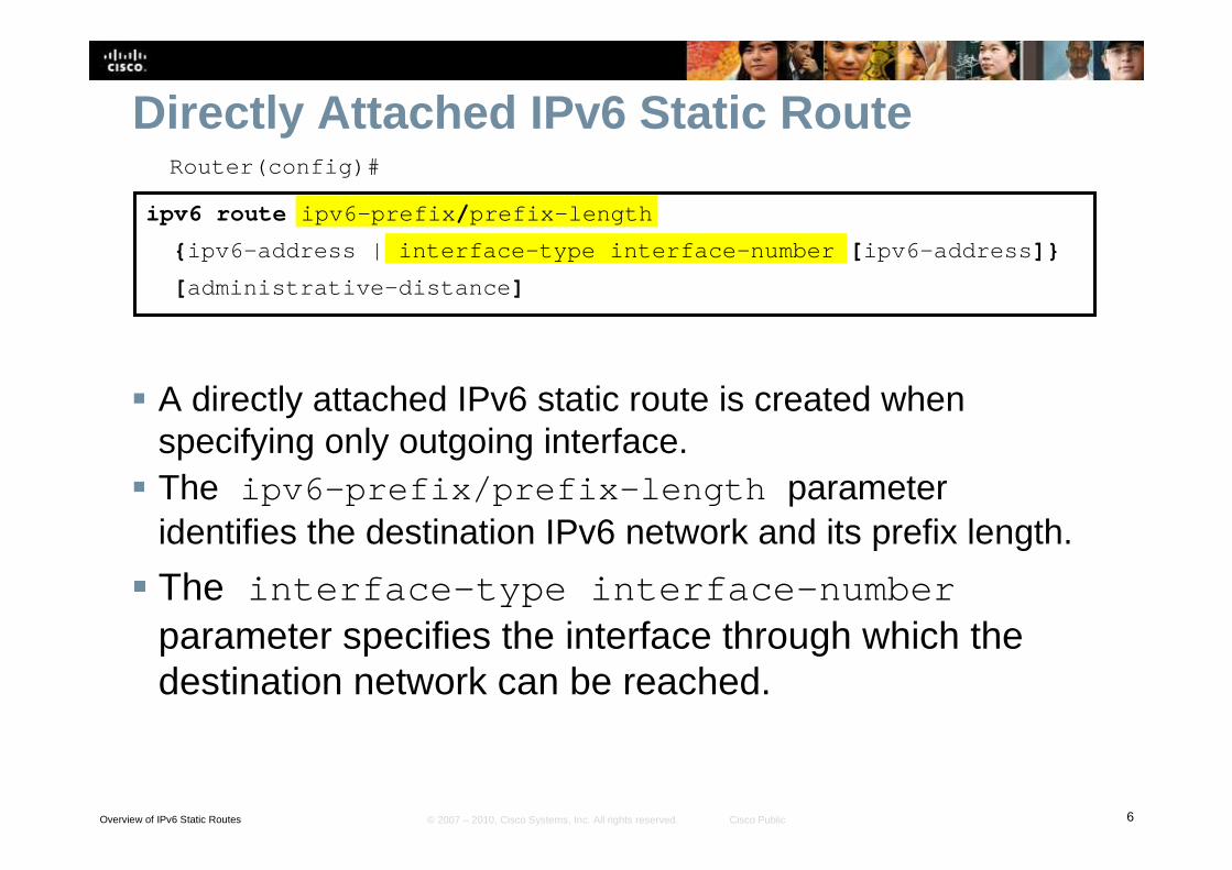
Directly Attached IPv6 Static RouteRouter(config)#
ipv6 route ipv6-prefix/prefix-length
{ipv6-address | interface-type interface-number [ipv6-address]}
[administrative-distance]
� A directly attached IPv6 static route is created when specifying only outgoing interface.
� The interface-type interface-number parameter specifies the interface through which the destination network can be reached.
� The ipv6-prefix/prefix-length parameter identifies the destination IPv6 network and its prefix length.
Overview of IPv6 Static Routes 7© 2007 – 2010, Cisco Systems, Inc. All rights reserved. Cisco Public
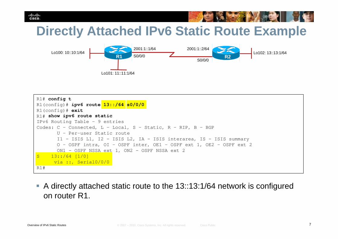
Directly Attached IPv6 Static Route Example
� A directly attached static route to the 13::13:1/64 network is configured on router R1.
R1# config tR1(config)# ipv6 route 13::/64 s0/0/0R1(config)# exitR1#
2001:1::1/64
S0/0/0S0/0/0
R1Lo102: 13::13:1/64
2001:1::2/64
R2Lo100: 10::10:1/64
Lo101: 11::11:1/64
show ipv6 route staticIPv6 Routing Table – 9 entriesCodes: C – Connected, L – Local, S – Static, R – RIP, B – BGP
U – Per-user Static routeI1 – ISIS L1, I2 – ISIS L2, IA – ISIS interarea, IS – I SIS summaryO – OSPF intra, OI – OSPF inter, OE1 – OSPF ext 1, OE2 – OSPF ext 2ON1 – OSPF NSSA ext 1, ON2 – OSPF NSSA ext 2
S 13::/64 [1/0]via ::, Serial0/0/0
R1#
Overview of IPv6 Static Routes 8© 2007 – 2010, Cisco Systems, Inc. All rights reserved. Cisco Public
Overview of IPv6 Static Routes 9© 2007 – 2010, Cisco Systems, Inc. All rights reserved. Cisco Public
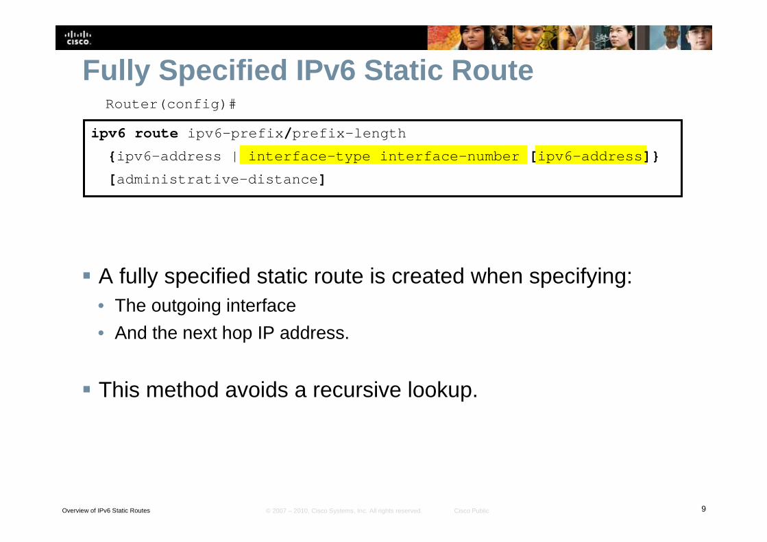
Fully Specified IPv6 Static RouteRouter(config)#
ipv6 route ipv6-prefix/prefix-length
{ipv6-address | interface-type interface-number [ipv6-address]}
[administrative-distance]
� A fully specified static route is created when specifying:• The outgoing interface
• And the next hop IP address.
� This method avoids a recursive lookup.
Overview of IPv6 Static Routes 10© 2007 – 2010, Cisco Systems, Inc. All rights reserved. Cisco Public
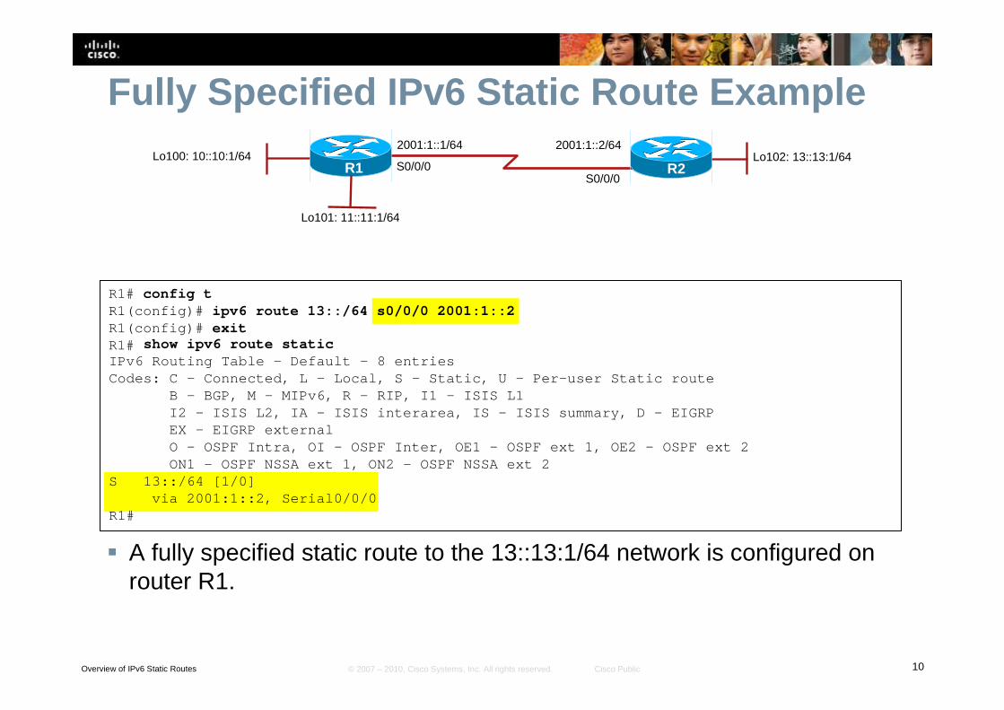
Fully Specified IPv6 Static Route Example
� A fully specified static route to the 13::13:1/64 network is configured on router R1.
R1# config tR1(config)# ipv6 route 13::/64 s0/0/0 2001:1::2R1(config)# exitR1#
2001:1::1/64
S0/0/0S0/0/0
R1Lo102: 13::13:1/64
2001:1::2/64
R2Lo100: 10::10:1/64
Lo101: 11::11:1/64
show ipv6 route staticIPv6 Routing Table - Default - 8 entriesCodes: C - Connected, L - Local, S - Static, U - Per-us er Static route
B - BGP, M - MIPv6, R - RIP, I1 - ISIS L1I2 - ISIS L2, IA - ISIS interarea, IS - ISIS summary, D - EIGRPEX - EIGRP externalO - OSPF Intra, OI - OSPF Inter, OE1 - OSPF ext 1, OE2 - OSPF ext 2ON1 - OSPF NSSA ext 1, ON2 - OSPF NSSA ext 2
S 13::/64 [1/0]via 2001:1::2, Serial0/0/0
R1#
Overview of IPv6 Static Routes 11© 2007 – 2010, Cisco Systems, Inc. All rights reserved. Cisco Public
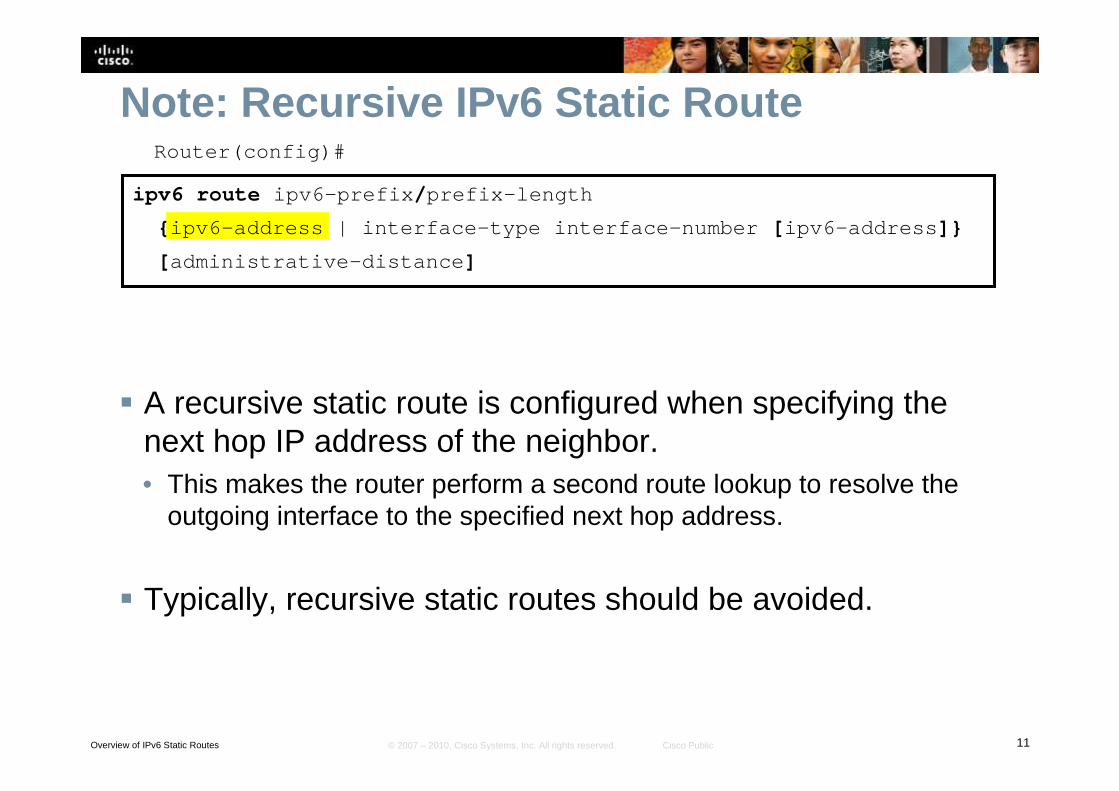
Note: Recursive IPv6 Static RouteRouter(config)#
ipv6 route ipv6-prefix/prefix-length
{ipv6-address | interface-type interface-number [ipv6-address]}
[administrative-distance]
� A recursive static route is configured when specifying the next hop IP address of the neighbor.• This makes the router perform a second route lookup to resolve the
outgoing interface to the specified next hop address.
� Typically, recursive static routes should be avoided.
Overview of IPv6 Static Routes 12© 2007 – 2010, Cisco Systems, Inc. All rights reserved. Cisco Public
Overview of IPv6 Static Routes 13© 2007 – 2010, Cisco Systems, Inc. All rights reserved. Cisco Public
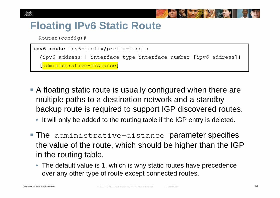
Floating IPv6 Static RouteRouter(config)#
ipv6 route ipv6-prefix/prefix-length
{ipv6-address | interface-type interface-number [ipv6-address]}
[administrative-distance]
� A floating static route is usually configured when there are multiple paths to a destination network and a standby backup route is required to support IGP discovered routes.• It will only be added to the routing table if the IGP entry is deleted.
� The administrative-distance parameter specifies the value of the route, which should be higher than the IGP in the routing table.• The default value is 1, which is why static routes have precedence
over any other type of route except connected routes.
Overview of IPv6 Static Routes 14© 2007 – 2010, Cisco Systems, Inc. All rights reserved. Cisco Public
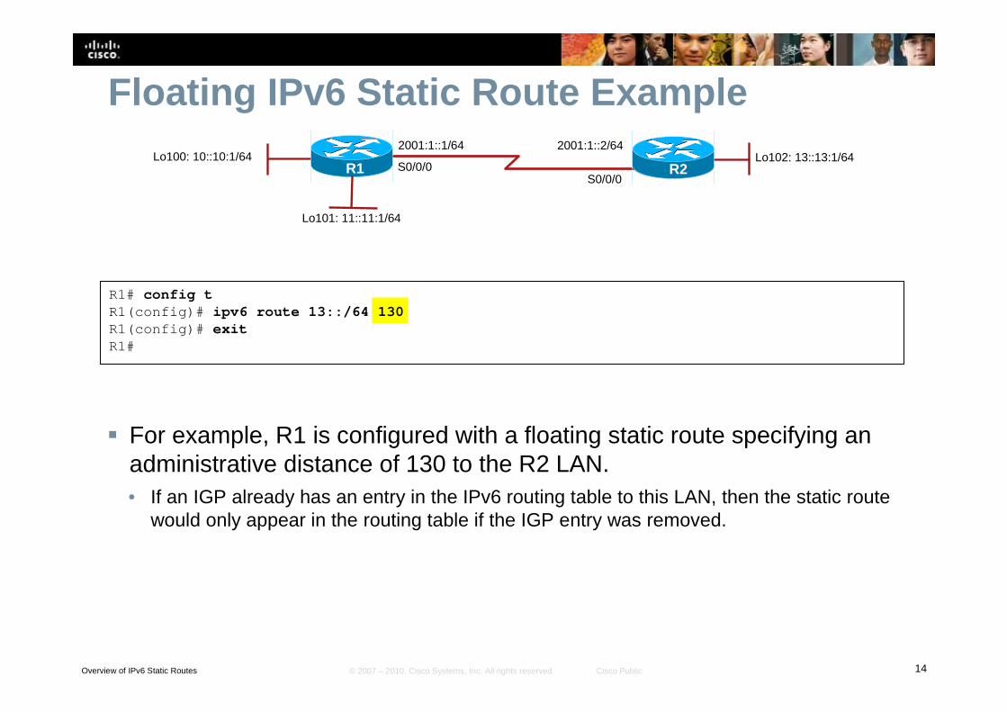
Floating IPv6 Static Route Example
� For example, R1 is configured with a floating static route specifying an administrative distance of 130 to the R2 LAN.• If an IGP already has an entry in the IPv6 routing table to this LAN, then the static route
would only appear in the routing table if the IGP entry was removed.
R1# config tR1(config)# ipv6 route 13::/64 130R1(config)# exitR1#
2001:1::1/64
S0/0/0S0/0/0
R1Lo102: 13::13:1/64
2001:1::2/64
R2Lo100: 10::10:1/64
Lo101: 11::11:1/64
Overview of IPv6 Static Routes 15© 2007 – 2010, Cisco Systems, Inc. All rights reserved. Cisco Public
Overview of IPv6 Static Routes 16© 2007 – 2010, Cisco Systems, Inc. All rights reserved. Cisco Public
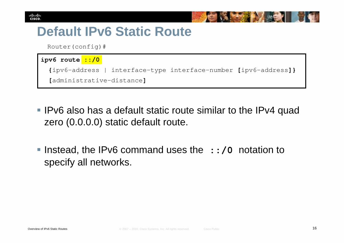
Default IPv6 Static RouteRouter(config)#
ipv6 route ::/0
{ipv6-address | interface-type interface-number [ipv6-address]}
[administrative-distance]
� IPv6 also has a default static route similar to the IPv4 quad zero (0.0.0.0) static default route.
� Instead, the IPv6 command uses the ::/0 notation to specify all networks.
Overview of IPv6 Static Routes 17© 2007 – 2010, Cisco Systems, Inc. All rights reserved. Cisco Public
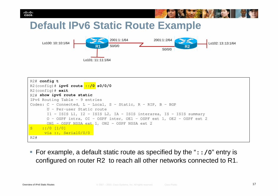
Default IPv6 Static Route Example
� For example, a default static route as specified by the “::/0” entry is configured on router R2 to reach all other networks connected to R1.
R2# config tR2(config)# ipv6 route ::/0 s0/0/0R2(config)# exitR2#
2001:1::1/64
S0/0/0S0/0/0
R1Lo102: 13::13:1/64
2001:1::2/64
R2Lo100: 10::10:1/64
Lo101: 11::11:1/64
show ipv6 route staticIPv6 Routing Table – 9 entriesCodes: C – Connected, L – Local, S – Static, R – RIP, B – BGP
U – Per-user Static routeI1 – ISIS L1, I2 – ISIS L2, IA – ISIS interarea, IS – I SIS summaryO – OSPF intra, OI – OSPF inter, OE1 – OSPF ext 1, OE2 – OSPF ext 2ON1 – OSPF NSSA ext 1, ON2 – OSPF NSSA ext 2
S ::/0 [1/0]via ::, Serial0/0/0
R2#

Overview of IPv6 Static Routes 18© 2007 – 2010, Cisco Systems, Inc. All rights reserved. Cisco Public
© 2007 – 2010, Cisco Systems, Inc. All rights reserved. Cisco Public 1
Transitioning IPv4 to IPv6
2© 2007 – 2010, Cisco Systems, Inc. All rights reserved. Cisco Public
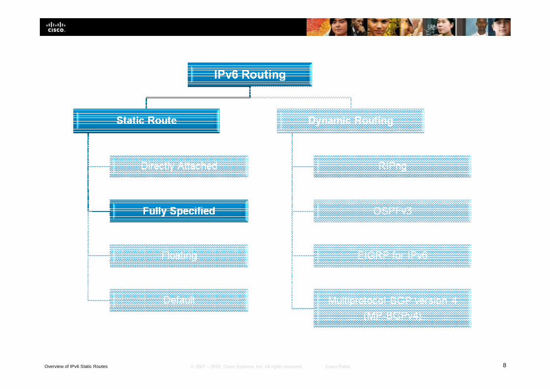
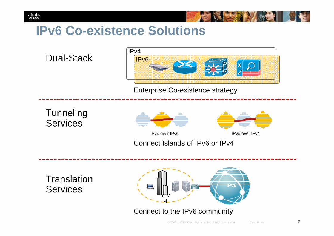
IPv6 Co-existence Solutions
Tunneling Services
Connect Islands of IPv6 or IPv4
IPv4 over IPv6 IPv6 over IPv4
Dual-Stack
Enterprise Co-existence strategy
TranslationServices
Connect to the IPv6 community
IPv4
IPv6
Internet consumers
Remote Workers
International SitesGovernment Agencies
IPv6IPv4

3© 2007 – 2010, Cisco Systems, Inc. All rights reserved. Cisco Public
Dual Stack
4© 2007 – 2010, Cisco Systems, Inc. All rights reserved. Cisco Public
Dual-Stack Techniques� Hosts and network devices run both IPv4 and IPv6 at the
same time. • This technique is useful as a temporary transition, but it adds
overhead and uses many resources.
� Cisco IOS Software is IPv6 ready.• As soon as IPv4 and IPv6 configurations are complete, the interface is
dual stacked and it forwards both IPv4 and IPv6 traffic.
� Drawback of dual stacking includes:• The additional resources required to keep and process dual routing
tables, routing protocol topology tables, etc.
• The higher administrative overhead, troubleshooting, and monitoring, is more complex.
5© 2007 – 2010, Cisco Systems, Inc. All rights reserved. Cisco Public
Dual-Stack Example
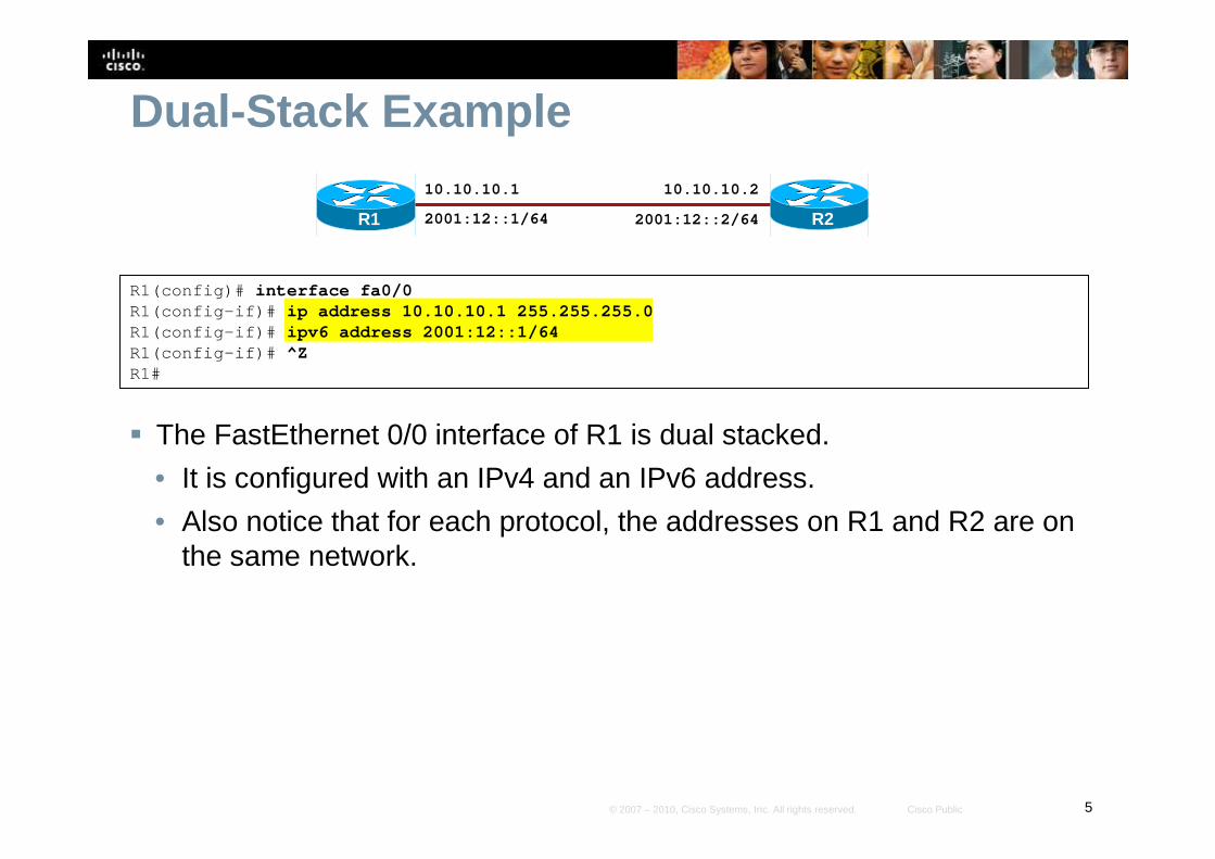
� The FastEthernet 0/0 interface of R1 is dual stacked.
• It is configured with an IPv4 and an IPv6 address.
• Also notice that for each protocol, the addresses on R1 and R2 are on the same network.
R2
10.10.10.1
R1
R1(config)# interface fa0/0R1(config-if)# ip address 10.10.10.1 255.255.255.0R1(config-if)# ipv6 address 2001:12::1/64R1(config-if)# ^ZR1#
10.10.10.2
2001:12::1/64 2001:12::2/64
6© 2007 – 2010, Cisco Systems, Inc. All rights reserved. Cisco Public
Dual-Stack Example
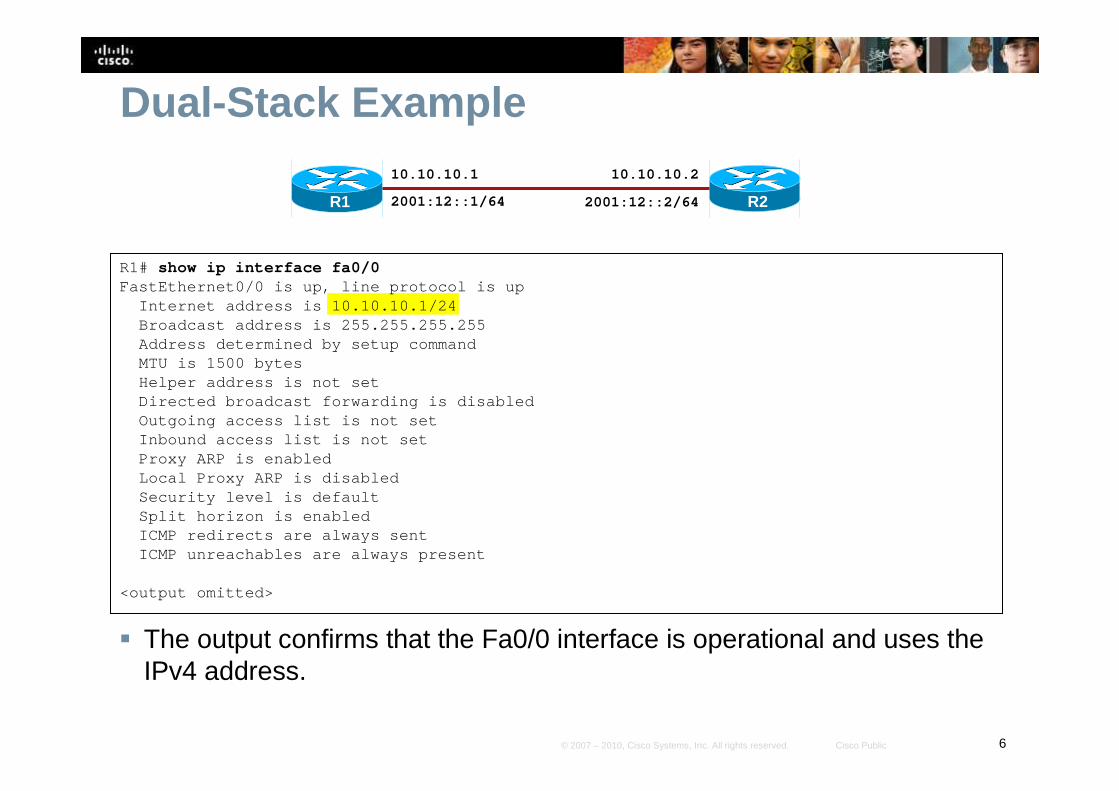
� The output confirms that the Fa0/0 interface is operational and uses the IPv4 address.
R1# show ip interface fa0/0FastEthernet0/0 is up, line protocol is up
Internet address is 10.10.10.1/24Broadcast address is 255.255.255.255Address determined by setup commandMTU is 1500 bytesHelper address is not setDirected broadcast forwarding is disabledOutgoing access list is not setInbound access list is not setProxy ARP is enabledLocal Proxy ARP is disabledSecurity level is defaultSplit horizon is enabledICMP redirects are always sentICMP unreachables are always present
<output omitted>
R2
10.10.10.1
R1
10.10.10.2
2001:12::1/64 2001:12::2/64
7© 2007 – 2010, Cisco Systems, Inc. All rights reserved. Cisco Public
Dual-Stack Example
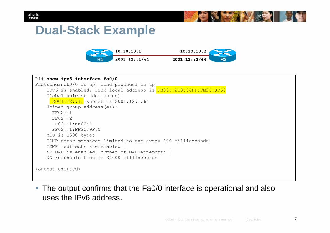
� The output confirms that the Fa0/0 interface is operational and also uses the IPv6 address.
R1# show ipv6 interface fa0/0FastEthernet0/0 is up, line protocol is up
IPv6 is enabled, link-local address is FE80::219:56 FF:FE2C:9F60Global unicast address(es):
2001:12::1, subnet is 2001:12::/64Joined group address(es):
FF02::1FF02::2FF02::1:FF00:1FF02::1:FF2C:9F60
MTU is 1500 bytesICMP error messages limited to one every 100 millis econdsICMP redirects are enabledND DAD is enabled, number of DAD attempts: 1ND reachable time is 30000 milliseconds
<output omitted>
R2
10.10.10.1
R1
10.10.10.2
2001:12::1/64 2001:12::2/64

8© 2007 – 2010, Cisco Systems, Inc. All rights reserved. Cisco Public
Tunneling
9© 2007 – 2010, Cisco Systems, Inc. All rights reserved. Cisco Public
Tunneling Techniques� Isolated IPv6 networks are connected over an IPv4
infrastructure using tunnels.
� The edge devices are the only ones that need to be dual-stacked.
� Scalability may be an issue if many tunnels need to be created.• Tunnels can be either manually or automatically configured,
depending on the scale required and administrative overhead tolerated.
10© 2007 – 2010, Cisco Systems, Inc. All rights reserved. Cisco Public
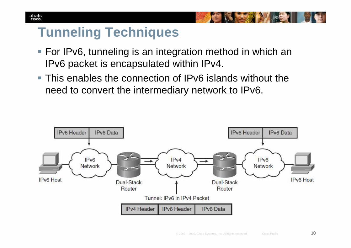
Tunneling Techniques� For IPv6, tunneling is an integration method in which an
IPv6 packet is encapsulated within IPv4.
� This enables the connection of IPv6 islands without the need to convert the intermediary network to IPv6.
11© 2007 – 2010, Cisco Systems, Inc. All rights reserved. Cisco Public
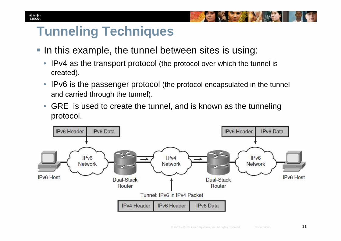
Tunneling Techniques� In this example, the tunnel between sites is using:
• IPv4 as the transport protocol (the protocol over which the tunnel is created).
• IPv6 is the passenger protocol (the protocol encapsulated in the tunnel and carried through the tunnel).
• GRE is used to create the tunnel, and is known as the tunnelingprotocol.
12© 2007 – 2010, Cisco Systems, Inc. All rights reserved. Cisco Public
Types of Tunnels� Tunnels can be created manually using:
• Manual IPv6 tunnels
• GRE IPv6 tunnels (not covered in this presentation)
� Tunnels can also be created automatically using:• IPv4-Compatible IPv6 Tunnels (now deprecated)
• 6to4 tunnels
• ISATAP Tunnels

13© 2007 – 2010, Cisco Systems, Inc. All rights reserved. Cisco Public
Manual Tunnels
14© 2007 – 2010, Cisco Systems, Inc. All rights reserved. Cisco Public
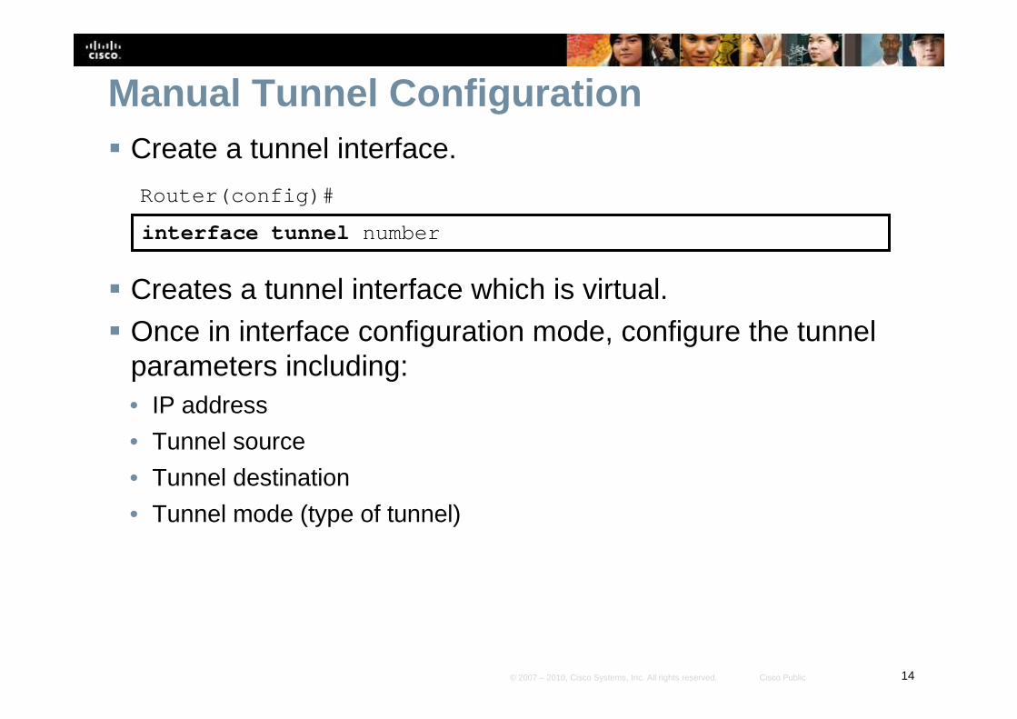
Manual Tunnel Configuration� Create a tunnel interface.
Router(config)#
interface tunnel number
� Creates a tunnel interface which is virtual.
� Once in interface configuration mode, configure the tunnel parameters including:• IP address
• Tunnel source
• Tunnel destination
• Tunnel mode (type of tunnel)
15© 2007 – 2010, Cisco Systems, Inc. All rights reserved. Cisco Public
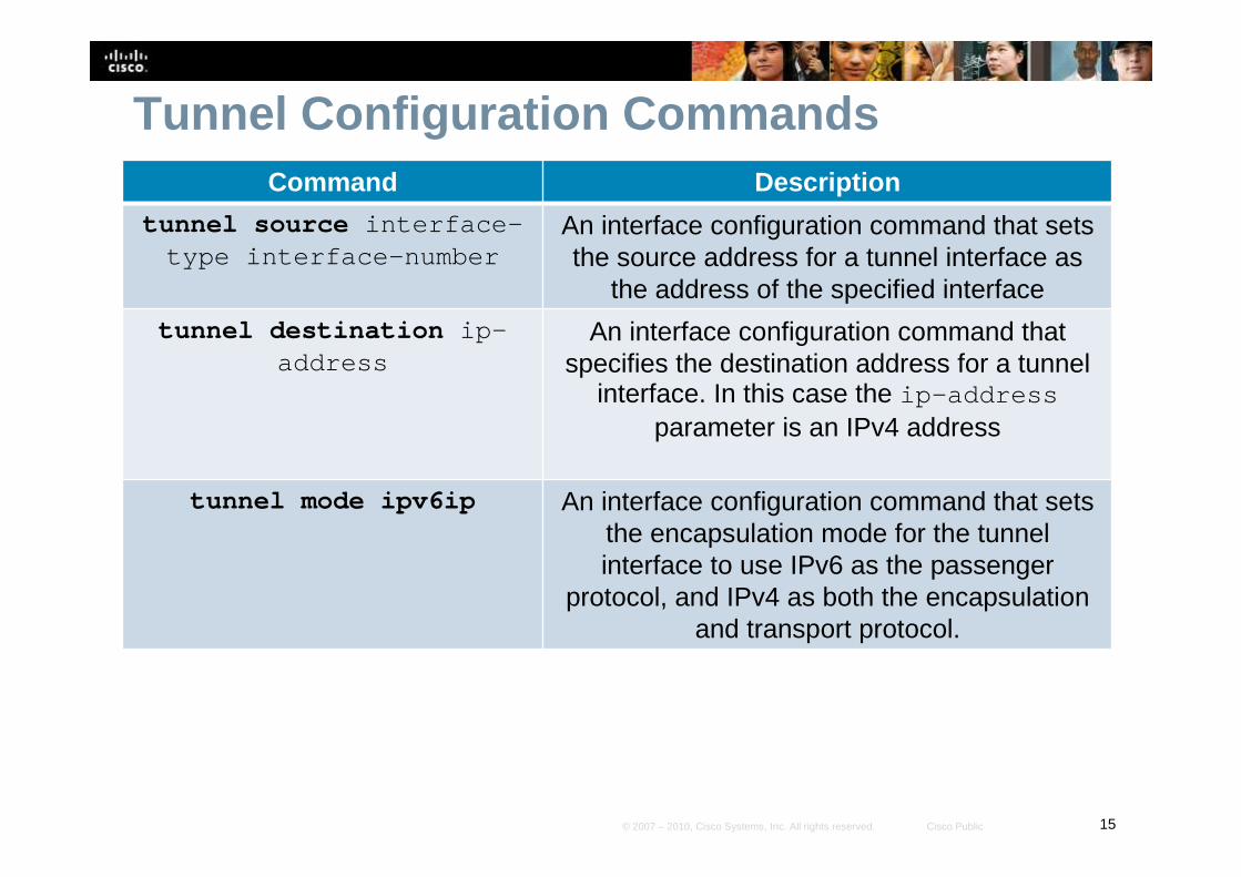
Tunnel Configuration CommandsCommand Description
tunnel source interface-type interface-number
An interface configuration command that sets the source address for a tunnel interface as
the address of the specified interface
tunnel destination ip-address
An interface configuration command that specifies the destination address for a tunnel
interface. In this case the ip-addressparameter is an IPv4 address
tunnel mode ipv6ip An interface configuration command that sets the encapsulation mode for the tunnel interface to use IPv6 as the passenger
protocol, and IPv4 as both the encapsulation and transport protocol.
16© 2007 – 2010, Cisco Systems, Inc. All rights reserved. Cisco Public
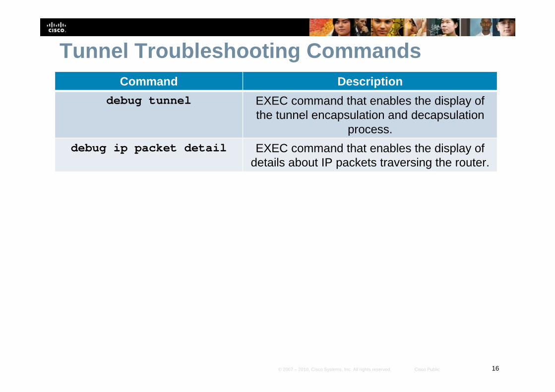
Tunnel Troubleshooting CommandsCommand Description
debug tunnel EXEC command that enables the display of the tunnel encapsulation and decapsulation
process.
debug ip packet detail EXEC command that enables the display of details about IP packets traversing the router.
17© 2007 – 2010, Cisco Systems, Inc. All rights reserved. Cisco Public
Manual IPv6 Tunnel Example
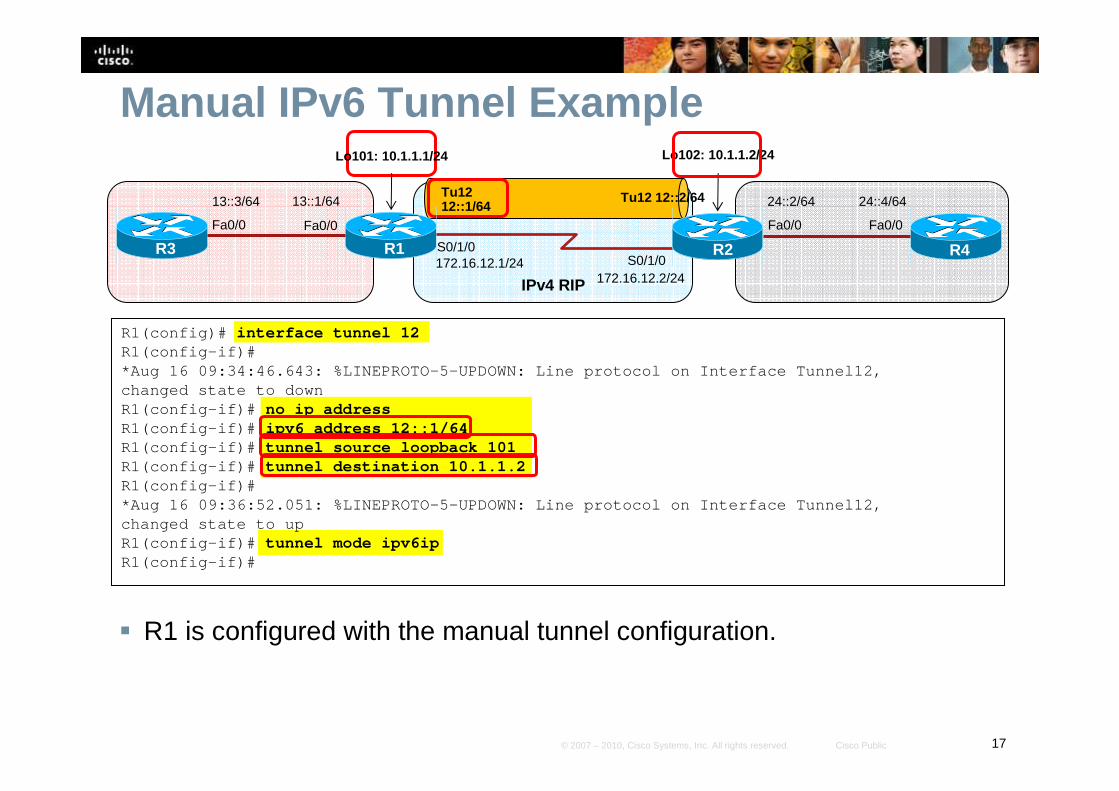
� R1 is configured with the manual tunnel configuration.
R1(config)# interface tunnel 12R1(config-if)#*Aug 16 09:34:46.643: %LINEPROTO-5-UPDOWN: Line pro tocol on Interface Tunnel12,changed state to downR1(config-if)# no ip addressR1(config-if)# ipv6 address 12::1/64R1(config-if)# tunnel source loopback 101R1(config-if)# tunnel destination 10.1.1.2R1(config-if)#*Aug 16 09:36:52.051: %LINEPROTO-5-UPDOWN: Line pro tocol on Interface Tunnel12,changed state to upR1(config-if)# tunnel mode ipv6ipR1(config-if)#
S0/1/0S0/1/0
R1 R2
IPv4 RIP
Fa0/0
13::1/64
R3
Fa0/0
13::3/64 24::4/64
R4
Fa0/0
24::2/64
Fa0/0
Lo101: 10.1.1.1/24 Lo102: 10.1.1.2/24
Tu12 12::2/64Tu12 12::1/64
172.16.12.1/24172.16.12.2/24
18© 2007 – 2010, Cisco Systems, Inc. All rights reserved. Cisco Public
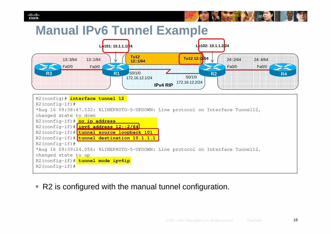
Manual IPv6 Tunnel Example
� R2 is configured with the manual tunnel configuration.
R2(config)# interface tunnel 12R2(config-if)#*Aug 16 09:38:47.532: %LINEPROTO-5-UPDOWN: Line pro tocol on Interface Tunnel12,changed state to downR2(config-if)# no ip addressR2(config-if)# ipv6 address 12::2/64R2(config-if)# tunnel source loopback 101R2(config-if)# tunnel destination 10.1.1.1R2(config-if)#*Aug 16 09:39:24.056: %LINEPROTO-5-UPDOWN: Line pro tocol on Interface Tunnel12,changed state to upR2(config-if)# tunnel mode ipv6ipR2(config-if)#
S0/1/0S0/1/0
R1 R2
IPv4 RIP
Fa0/0
13::1/64
R3
Fa0/0
13::3/64 24::4/64
R4
Fa0/0
24::2/64
Fa0/0
Lo101: 10.1.1.1/24 Lo102: 10.1.1.2/24
Tu12 12::2/64Tu12 12::1/64
172.16.12.1/24172.16.12.2/24
19© 2007 – 2010, Cisco Systems, Inc. All rights reserved. Cisco Public
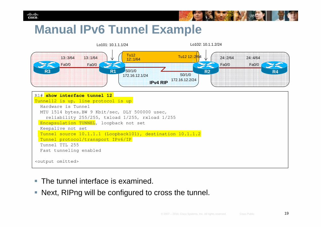
Manual IPv6 Tunnel Example
� The tunnel interface is examined.
� Next, RIPng will be configured to cross the tunnel.
R1# show interface tunnel 12Tunnel12 is up, line protocol is up
Hardware is TunnelMTU 1514 bytes,BW 9 Kbit/sec, DLY 500000 usec,
reliability 255/255, txload 1/255, rxload 1/255Encapsulation TUNNEL, loopback not setKeepalive not setTunnel source 10.1.1.1 (Loopback101), destination 1 0.1.1.2Tunnel protocol/transport IPv6/IPTunnel TTL 255Fast tunneling enabled
<output omitted>
S0/1/0S0/1/0
R1 R2
IPv4 RIP
Fa0/0
13::1/64
R3
Fa0/0
13::3/64 24::4/64
R4
Fa0/0
24::2/64
Fa0/0
Lo101: 10.1.1.1/24 Lo102: 10.1.1.2/24
Tu12 12::2/64Tu12 12::1/64
172.16.12.1/24172.16.12.2/24
20© 2007 – 2010, Cisco Systems, Inc. All rights reserved. Cisco Public
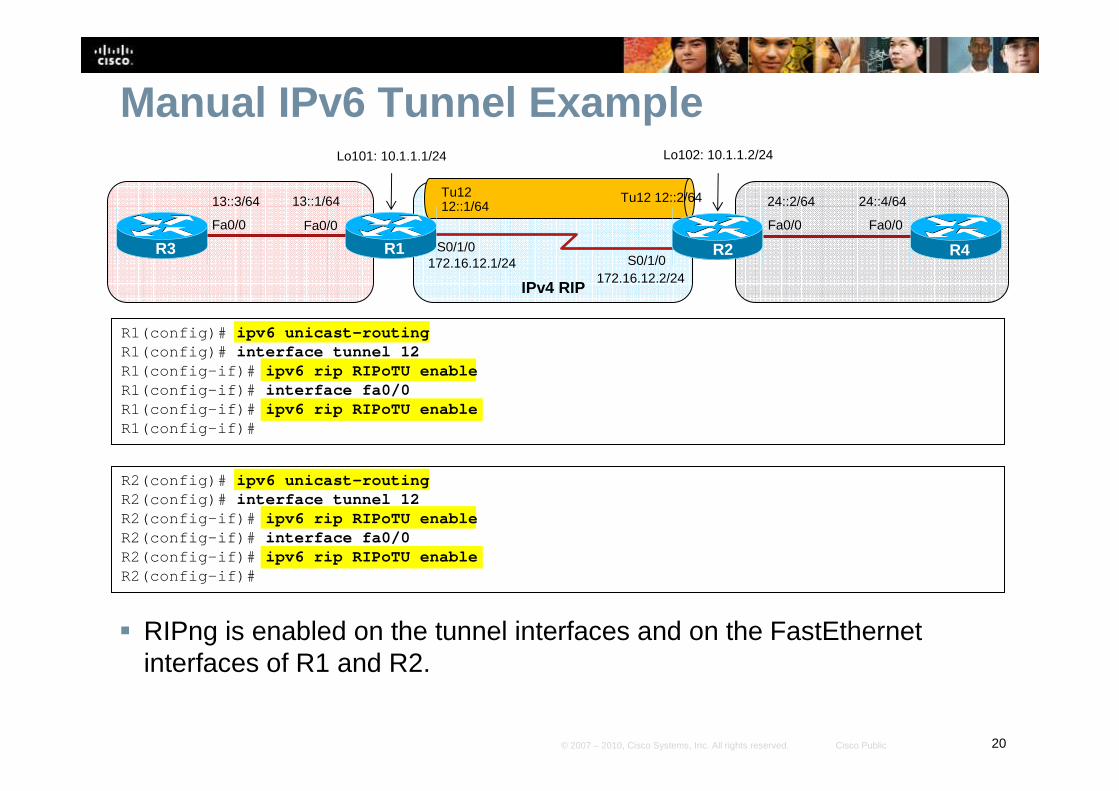
Manual IPv6 Tunnel Example
� RIPng is enabled on the tunnel interfaces and on the FastEthernet interfaces of R1 and R2.
R1(config)# ipv6 unicast-routingR1(config)# interface tunnel 12R1(config-if)# ipv6 rip RIPoTU enableR1(config-if)# interface fa0/0R1(config-if)# ipv6 rip RIPoTU enableR1(config-if)#
R2(config)# ipv6 unicast-routingR2(config)# interface tunnel 12R2(config-if)# ipv6 rip RIPoTU enableR2(config-if)# interface fa0/0R2(config-if)# ipv6 rip RIPoTU enableR2(config-if)#
S0/1/0S0/1/0
R1 R2
IPv4 RIP
Fa0/0
13::1/64
R3
Fa0/0
13::3/64 24::4/64
R4
Fa0/0
24::2/64
Fa0/0
Lo101: 10.1.1.1/24 Lo102: 10.1.1.2/24
Tu12 12::2/64Tu12 12::1/64
172.16.12.1/24172.16.12.2/24
21© 2007 – 2010, Cisco Systems, Inc. All rights reserved. Cisco Public
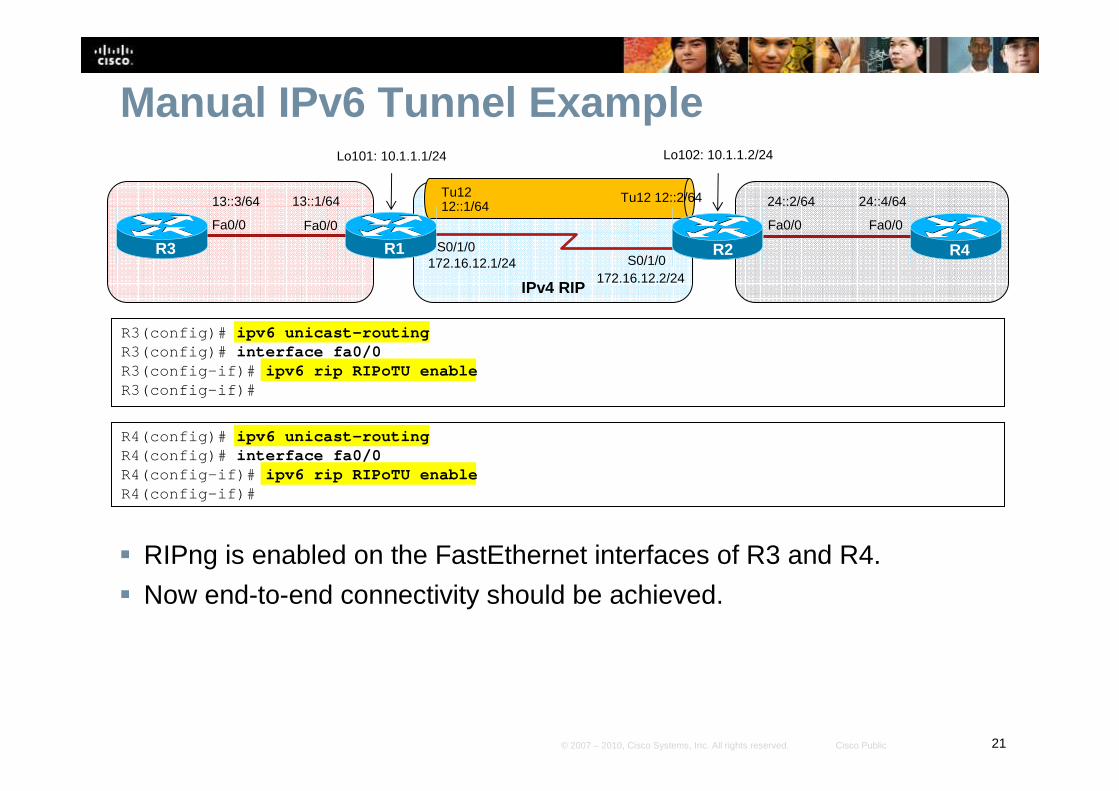
Manual IPv6 Tunnel Example
� RIPng is enabled on the FastEthernet interfaces of R3 and R4.
� Now end-to-end connectivity should be achieved.
R3(config)# ipv6 unicast-routingR3(config)# interface fa0/0R3(config-if)# ipv6 rip RIPoTU enableR3(config-if)#
R4(config)# ipv6 unicast-routingR4(config)# interface fa0/0R4(config-if)# ipv6 rip RIPoTU enableR4(config-if)#
S0/1/0S0/1/0
R1 R2
IPv4 RIP
Fa0/0
13::1/64
R3
Fa0/0
13::3/64 24::4/64
R4
Fa0/0
24::2/64
Fa0/0
Lo101: 10.1.1.1/24 Lo102: 10.1.1.2/24
Tu12 12::2/64Tu12 12::1/64
172.16.12.1/24172.16.12.2/24
22© 2007 – 2010, Cisco Systems, Inc. All rights reserved. Cisco Public
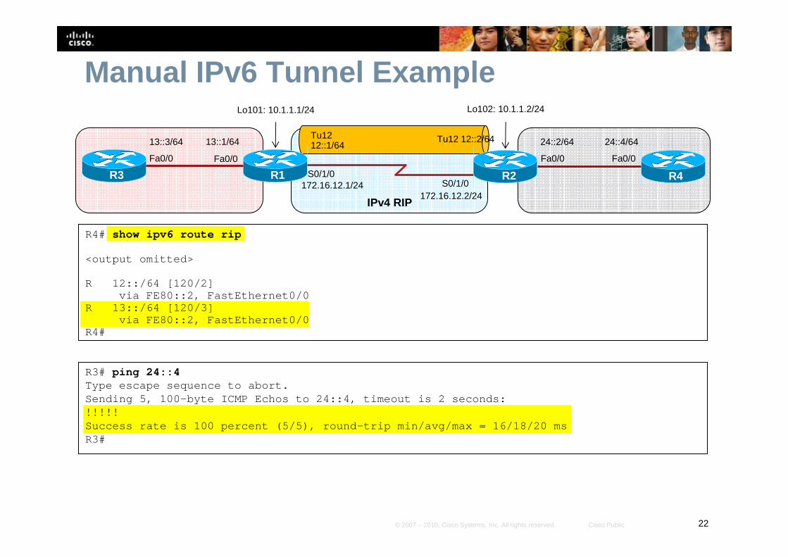
Manual IPv6 Tunnel Example
R4# show ipv6 route rip
<output omitted>
R 12::/64 [120/2]via FE80::2, FastEthernet0/0
R 13::/64 [120/3]via FE80::2, FastEthernet0/0
R4#
R3# ping 24::4Type escape sequence to abort.Sending 5, 100-byte ICMP Echos to 24::4, timeout is 2 seconds:!!!!!Success rate is 100 percent (5/5), round-trip min/a vg/max = 16/18/20 msR3#
S0/1/0S0/1/0
R1 R2
IPv4 RIP
Fa0/0
13::1/64
R3
Fa0/0
13::3/64 24::4/64
R4
Fa0/0
24::2/64
Fa0/0
Lo101: 10.1.1.1/24 Lo102: 10.1.1.2/24
Tu12 12::2/64Tu12 12::1/64
172.16.12.1/24172.16.12.2/24
23© 2007 – 2010, Cisco Systems, Inc. All rights reserved. Cisco Public
Manual IPv6 Tunnel Summary� Manual tunnels are simple to configure, and are therefore
useful for a small number of sites.
� However, for large networks manual tunnels are not scalable, from both a configuration and management perspective.
� The edge routers on which the tunnels terminate need to be dual stacked, and therefore must be capable of running both protocols and have the capacity to do so.

24© 2007 – 2010, Cisco Systems, Inc. All rights reserved. Cisco Public
6to4 Tunnels
25© 2007 – 2010, Cisco Systems, Inc. All rights reserved. Cisco Public
6to4 Tunnels� 6to4 tunnels, also known as a 6-to-4 tunnel, is an automatic
tunneling method.
� 6to4 tunnels are point-to-multipoint, rather than the point-to-point tunnels.
� The 6to4 tunnels are built automatically by the edge routers, based on embedded IPv4 address within the IPv6 addresses of the tunnel interfaces on the edge routers.
� 6to4 tunnels enable the fast deployment of IPv6 in a corporate network without the need for public IPv6 addresses from ISPs or registries.
26© 2007 – 2010, Cisco Systems, Inc. All rights reserved. Cisco Public
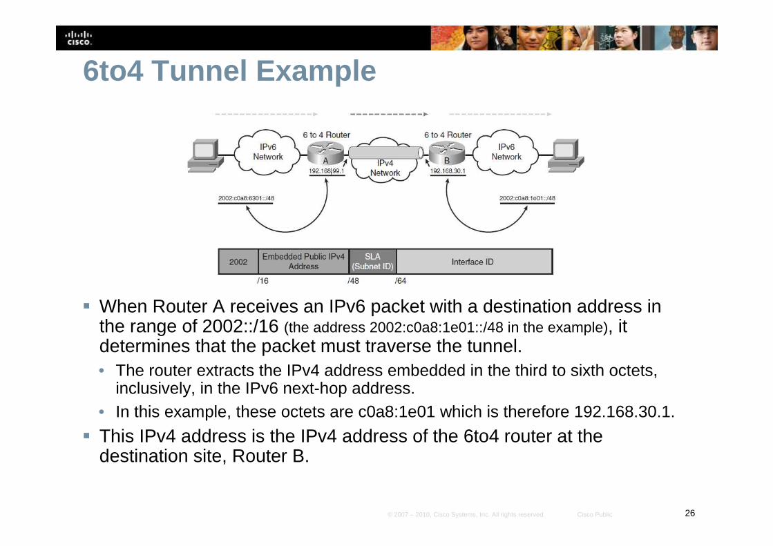
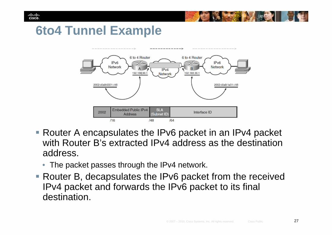
6to4 Tunnel Example
� When Router A receives an IPv6 packet with a destination address in the range of 2002::/16 (the address 2002:c0a8:1e01::/48 in the example), it determines that the packet must traverse the tunnel.• The router extracts the IPv4 address embedded in the third to sixth octets,
inclusively, in the IPv6 next-hop address. • In this example, these octets are c0a8:1e01 which is therefore 192.168.30.1.
� This IPv4 address is the IPv4 address of the 6to4 router at the destination site, Router B.
27© 2007 – 2010, Cisco Systems, Inc. All rights reserved. Cisco Public
6to4 Tunnel Example
� Router A encapsulates the IPv6 packet in an IPv4 packet with Router B’s extracted IPv4 address as the destination address. • The packet passes through the IPv4 network.
� Router B, decapsulates the IPv6 packet from the received IPv4 packet and forwards the IPv6 packet to its final destination.
28© 2007 – 2010, Cisco Systems, Inc. All rights reserved. Cisco Public
6to4 Limitations� Only static routes or BGP are supported.
• This is because the other routing protocols use link-local addresses to form adjacencies and exchange updates and these do not conform to the address requirements for 6to4 tunnels.
• The example presented here will use static routes.
� NAT cannot be used along the IPv4 path of the tunnel, again because of the 6to4 address requirements.
29© 2007 – 2010, Cisco Systems, Inc. All rights reserved. Cisco Public
6to4 Tunnel Example
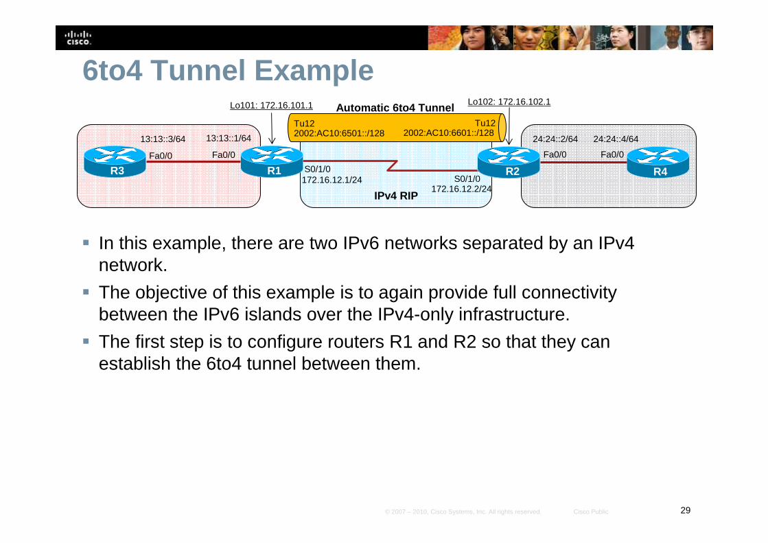
� In this example, there are two IPv6 networks separated by an IPv4 network.
� The objective of this example is to again provide full connectivity between the IPv6 islands over the IPv4-only infrastructure.
� The first step is to configure routers R1 and R2 so that they can establish the 6to4 tunnel between them.
S0/1/0S0/1/0
R1 R2
Fa0/0
13:13::1/64
R3Fa0/0
13:13::3/64 24:24::4/64
R4
Fa0/0
24:24::2/64
Fa0/0
Lo101: 172.16.101.1 Lo102: 172.16.102.1
172.16.12.1/24172.16.12.2/24
Automatic 6to4 TunnelTu122002:AC10:6501::/128
Tu122002:AC10:6601::/128
IPv4 RIP
30© 2007 – 2010, Cisco Systems, Inc. All rights reserved. Cisco Public
6to4 Tunnel Example
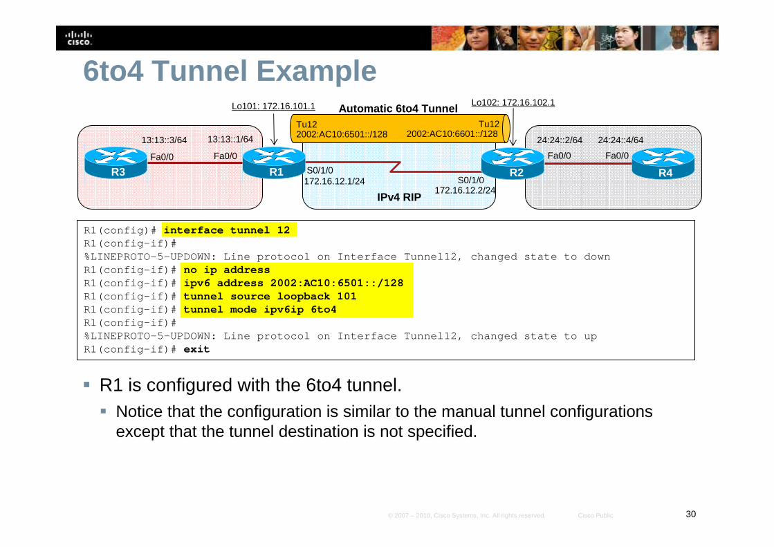
� R1 is configured with the 6to4 tunnel.� Notice that the configuration is similar to the manual tunnel configurations
except that the tunnel destination is not specified.
R1(config)# interface tunnel 12R1(config-if)#%LINEPROTO-5-UPDOWN: Line protocol on Interface Tun nel12, changed state to downR1(config-if)# no ip addressR1(config-if)# ipv6 address 2002:AC10:6501::/128R1(config-if)# tunnel source loopback 101R1(config-if)# tunnel mode ipv6ip 6to4R1(config-if)#%LINEPROTO-5-UPDOWN: Line protocol on Interface Tun nel12, changed state to upR1(config-if)# exit
S0/1/0S0/1/0
R1 R2
Fa0/0
13:13::1/64
R3Fa0/0
13:13::3/64 24:24::4/64
R4
Fa0/0
24:24::2/64
Fa0/0
Lo101: 172.16.101.1 Lo102: 172.16.102.1
172.16.12.1/24172.16.12.2/24
Automatic 6to4 TunnelTu122002:AC10:6501::/128
Tu122002:AC10:6601::/128
IPv4 RIP
31© 2007 – 2010, Cisco Systems, Inc. All rights reserved. Cisco Public
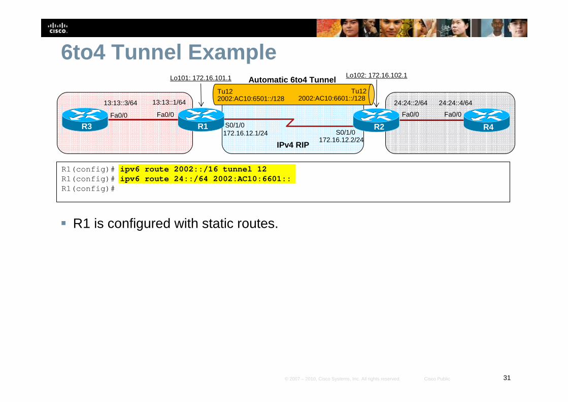
6to4 Tunnel Example
� R1 is configured with static routes.
R1(config)# ipv6 route 2002::/16 tunnel 12R1(config)# ipv6 route 24::/64 2002:AC10:6601::R1(config)#
S0/1/0S0/1/0
R1 R2
Fa0/0
13:13::1/64
R3Fa0/0
13:13::3/64 24:24::4/64
R4
Fa0/0
24:24::2/64
Fa0/0
Lo101: 172.16.101.1 Lo102: 172.16.102.1
172.16.12.1/24172.16.12.2/24
Automatic 6to4 TunnelTu122002:AC10:6501::/128
Tu122002:AC10:6601::/128
IPv4 RIP

32© 2007 – 2010, Cisco Systems, Inc. All rights reserved. Cisco Public
6to4 Tunnel Example
� R2 is configured with the 6to4 tunnel.
R2(config)# interface tunnel 12R2(config-if)#%LINEPROTO-5-UPDOWN: Line protocol on Interface Tun nel12, changed state to downR2(config-if)# no ip addressR2(config-if)# ipv6 address 2002:AC10:6601::/128R2(config-if)# tunnel source loopback 102R2(config-if)# tunnel mode ipv6ip 6to4R2(config-if)#%LINEPROTO-5-UPDOWN: Line protocol on Interface Tun nel12, changed state to upR2(config-if)# exit
S0/1/0S0/1/0
R1 R2
Fa0/0
13:13::1/64
R3Fa0/0
13:13::3/64 24:24::4/64
R4
Fa0/0
24:24::2/64
Fa0/0
Lo101: 172.16.101.1 Lo102: 172.16.102.1
172.16.12.1/24172.16.12.2/24
Automatic 6to4 TunnelTu122002:AC10:6501::/128
Tu122002:AC10:6601::/128
IPv4 RIP
33© 2007 – 2010, Cisco Systems, Inc. All rights reserved. Cisco Public
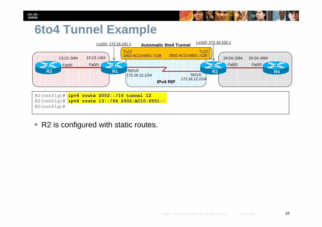
6to4 Tunnel Example
� R2 is configured with static routes.
R2(config)# ipv6 route 2002::/16 tunnel 12R2(config)# ipv6 route 13::/64 2002:AC10:6501::R2(config)#
S0/1/0S0/1/0
R1 R2
Fa0/0
13:13::1/64
R3Fa0/0
13:13::3/64 24:24::4/64
R4
Fa0/0
24:24::2/64
Fa0/0
Lo101: 172.16.101.1 Lo102: 172.16.102.1
172.16.12.1/24172.16.12.2/24
Automatic 6to4 TunnelTu122002:AC10:6501::/128
Tu122002:AC10:6601::/128
IPv4 RIP

34© 2007 – 2010, Cisco Systems, Inc. All rights reserved. Cisco Public
ISATAP Tunnels
35© 2007 – 2010, Cisco Systems, Inc. All rights reserved. Cisco Public
ISATAP Tunnels� An Intra-Site Automatic Tunnel Addressing Protocol
(ISATAP) tunnel is very similar to a 6to4 IPv6 tunnel.• It is used to connect IPv6 domains over an IPv4 network.
• It embeds an IPv4 address within the IPv6 address.
� The goal of ISATAP is to provide connectivity for IPv6 hosts to a centralized IPv6-capable router, over an IPv4-only access network.
� ISATAP was designed to transport IPv6 packets within a site (hence the “intra-site” part of its name). • It can still be used between sites, but its purpose is within sites.
� ISATAP tunnels use IPv6 addresses consisting of a 64-bit prefix concatenated to a 64-bit interface ID in EUI-64 format.
36© 2007 – 2010, Cisco Systems, Inc. All rights reserved. Cisco Public
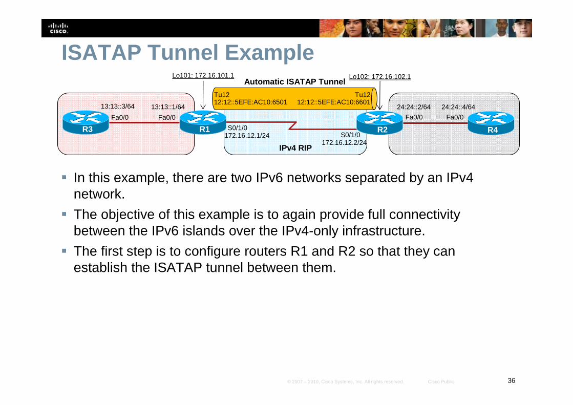
ISATAP Tunnel Example
� In this example, there are two IPv6 networks separated by an IPv4 network.
� The objective of this example is to again provide full connectivity between the IPv6 islands over the IPv4-only infrastructure.
� The first step is to configure routers R1 and R2 so that they can establish the ISATAP tunnel between them.
S0/1/0S0/1/0
R1 R2
Fa0/0
13:13::1/64
R3
Fa0/0
13:13::3/64 24:24::4/64
R4
Fa0/0
24:24::2/64
Fa0/0
Lo101: 172.16.101.1 Lo102: 172.16.102.1
172.16.12.1/24172.16.12.2/24
Automatic ISATAP Tunnel
Tu1212:12::5EFE:AC10:6501
Tu1212:12::5EFE:AC10:6601
IPv4 RIP

37© 2007 – 2010, Cisco Systems, Inc. All rights reserved. Cisco Public
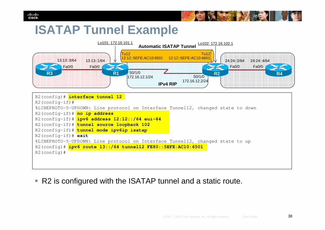
ISATAP Tunnel Example
� R1 is configured with the ISATAP tunnel and a static route.� Notice that the configuration is similar to the manual and GRE tunnel
configurations except that the tunnel destination is not specified.
R1(config)# interface tunnel 12R1(config-if)#%LINEPROTO-5-UPDOWN: Line protocol on Interface Tun nel12, changed state to downR1(config-if)# no ip addressR1(config-if)# ipv6 address 12:12::/64 eui-64R1(config-if)# tunnel source loopback 101R1(config-if)# tunnel mode ipv6ip isatapR1(config-if)# exit%LINEPROTO-5-UPDOWN: Line protocol on Interface Tun nel12, changed state to upR1(config)# ipv6 route 24::/64 tunnel12 FE80::5EFE:AC10:6601R1(config)#
S0/1/0S0/1/0
R1 R2
Fa0/0
13:13::1/64
R3
Fa0/0
13:13::3/64 24:24::4/64
R4
Fa0/0
24:24::2/64
Fa0/0
Lo101: 172.16.101.1 Lo102: 172.16.102.1
172.16.12.1/24172.16.12.2/24
Automatic ISATAP Tunnel
Tu1212:12::5EFE:AC10:6501
Tu1212:12::5EFE:AC10:6601
IPv4 RIP
38© 2007 – 2010, Cisco Systems, Inc. All rights reserved. Cisco Public
ISATAP Tunnel Example
� R2 is configured with the ISATAP tunnel and a static route.
R2(config)# interface tunnel 12R2(config-if)#%LINEPROTO-5-UPDOWN: Line protocol on Interface Tun nel12, changed state to downR2(config-if)# no ip addressR2(config-if)# ipv6 address 12:12::/64 eui-64R2(config-if)# tunnel source loopback 102R2(config-if)# tunnel mode ipv6ip isatapR2(config-if)# exit%LINEPROTO-5-UPDOWN: Line protocol on Interface Tun nel12, changed state to upR2(config)# ipv6 route 13::/64 tunnel12 FE80::5EFE:AC10:6501R2(config)#
S0/1/0S0/1/0
R1 R2
Fa0/0
13:13::1/64
R3
Fa0/0
13:13::3/64 24:24::4/64
R4
Fa0/0
24:24::2/64
Fa0/0
Lo101: 172.16.101.1 Lo102: 172.16.102.1
172.16.12.1/24172.16.12.2/24
Automatic ISATAP Tunnel
Tu1212:12::5EFE:AC10:6501
Tu1212:12::5EFE:AC10:6601
IPv4 RIP

39© 2007 – 2010, Cisco Systems, Inc. All rights reserved. Cisco Public
Translation Using NAT-PT
40© 2007 – 2010, Cisco Systems, Inc. All rights reserved. Cisco Public
NAT-PT� NAT-PT is a transition technique, but is not a replacement for dual stack
or tunneling. • It can be used in situations where direct communication between IPv6-only
and IPv4-only networks is desired.
• It would not be appropriate in situations where connectivity between two IPv6 networks is required, because two points of translation would be necessary, which would not be efficient or effective.
� With NAT-PT, all configuration and translation is performed on the NAT-PT router. • The other devices in the network are not aware of the existence of the other
protocol’s network, nor that translations are occurring.
� Note: NAT-PT has been moved to historical status with RFC 4966.
41© 2007 – 2010, Cisco Systems, Inc. All rights reserved. Cisco Public
Summary� This presentation covered transition mechanisms to aid in the transition from IPv4 to IPv6.
� Dual Stack• A device or network on which two protocol stacks have been enabled at the same time operates in
dual-stack mode.
• The primary advantage of dual-stack is that it does not require tunneling within the campus network. Dual-stack runs the two protocols as “ships-in-the-night”.
� Tunneling• A manually configured tunnel is equivalent to a permanent link between two IPv6 domains over an
IPv4 backbone.
• An automatic 6to4 tunnel allows isolated IPv6 domains to be connected over an IPv4 network to remote IPv6 networks. The key difference between automatic 6to4 tunnels and manually configured tunnels is that the tunnel is not point-to-point; it is point-to-multipoint.
• ISATAP tunneling mechanism is similar to other automatic tunneling mechanisms, such as IPv6 6to4 tunneling; however, ISATAP is designed for transporting IPv6 packets within a site, not between sites.
� NAT-PT• NAT-PT is designed to be deployed to allow direct communication between IPv6-only networks and
IPv4-only networks.
• One of the benefits of NAT-PT is that no changes are required to existing hosts, because all the NAT-PT configurations are performed at the NAT-PT router.
42© 2007 – 2010, Cisco Systems, Inc. All rights reserved. Cisco Public
Resources� Cisco IPv6
http://www.cisco.com/web/solutions/netsys/ipv6/index.html
� Cisco IOS IPv6 Configuration Guidehttp://www.cisco.com/en/US/docs/ios/ipv6/configuration/guide/12_4/ipv6_12_4_book.html
� Dual-Stack At-A-Glancehttp://www.cisco.com/en/US/prod/collateral/iosswrel/ps6537/ps6553/at_a_glance_c45-625859.pdf
�Implementing Tunneling for IPv6http://www.cisco.com/en/US/docs/ios/ipv6/configuration/guide/ip6-tun
nel.html
�RFC 4966http://www.apps.ietf.org/rfc/rfc4966.html

43© 2007 – 2010, Cisco Systems, Inc. All rights reserved. Cisco Public

44© 2007 – 2010, Cisco Systems, Inc. All rights reserved. Cisco Public
Appendix A:Translation Using NAT-PT
45© 2007 – 2010, Cisco Systems, Inc. All rights reserved. Cisco Public
NAT-PT� The NAT-PT router translates source and destination
addresses and other packet header fields in both directions: • From the IPv4 network to the IPv6 network
• From the IPv6 network to the IPv4 network.
� For this reason, this router is dual stacked and must have two sets of translation entries for this bidirectional translation.
46© 2007 – 2010, Cisco Systems, Inc. All rights reserved. Cisco Public
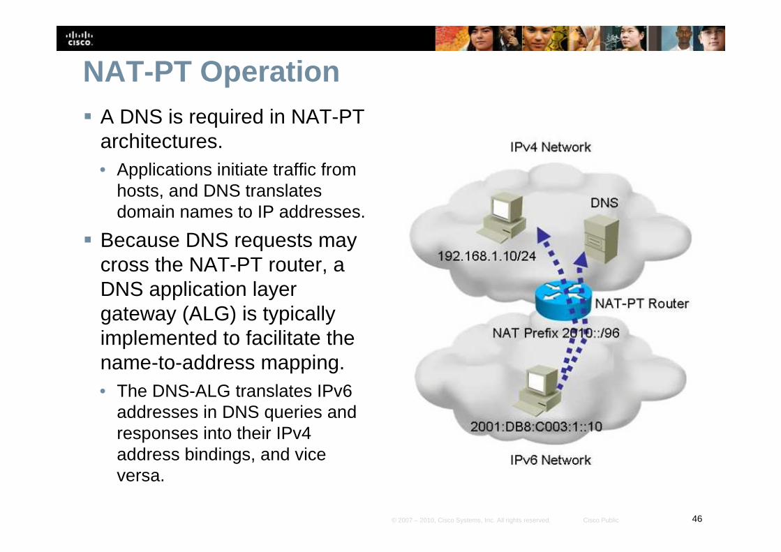
NAT-PT Operation� A DNS is required in NAT-PT
architectures.• Applications initiate traffic from
hosts, and DNS translates domain names to IP addresses.
� Because DNS requests may cross the NAT-PT router, a DNS application layer gateway (ALG) is typically implemented to facilitate the name-to-address mapping. • The DNS-ALG translates IPv6
addresses in DNS queries and responses into their IPv4 address bindings, and vice versa.
47© 2007 – 2010, Cisco Systems, Inc. All rights reserved. Cisco Public
NAT-PT� NAT-PT uses a 96-bit IPv6 network prefix to direct all IPv6 traffic that
needs to be translated to the NAT-PT router. • This prefix can be any routable prefix within the IPv6 domain.
• IPv6 routing must be configured such that all IPv6 packets addressed to this prefix are routed to the NAT-PT device.
� When the NAT-PT router receives an IPv6 packet destined for the NAT-PT prefix, it translates the packet according to the configured mapping rules. • This prefix is also used in the translation of IPv4 addresses into IPv6
addresses.
� Within the IPv6 domain, external IPv4 addresses are mapped to IPv6 addresses. • This mapping is done statically or dynamically.
• Similarly, static and dynamic mapping can be configured for translating internal IPv6 addresses to external IPv4 addresses.
48© 2007 – 2010, Cisco Systems, Inc. All rights reserved. Cisco Public
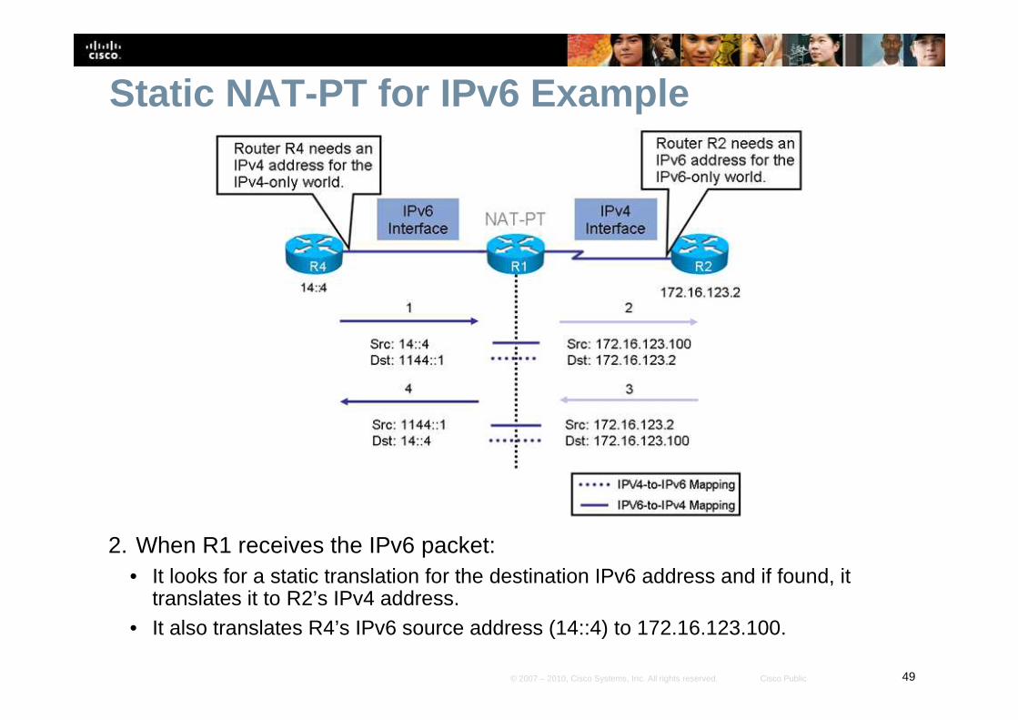
Static NAT-PT for IPv6 Example
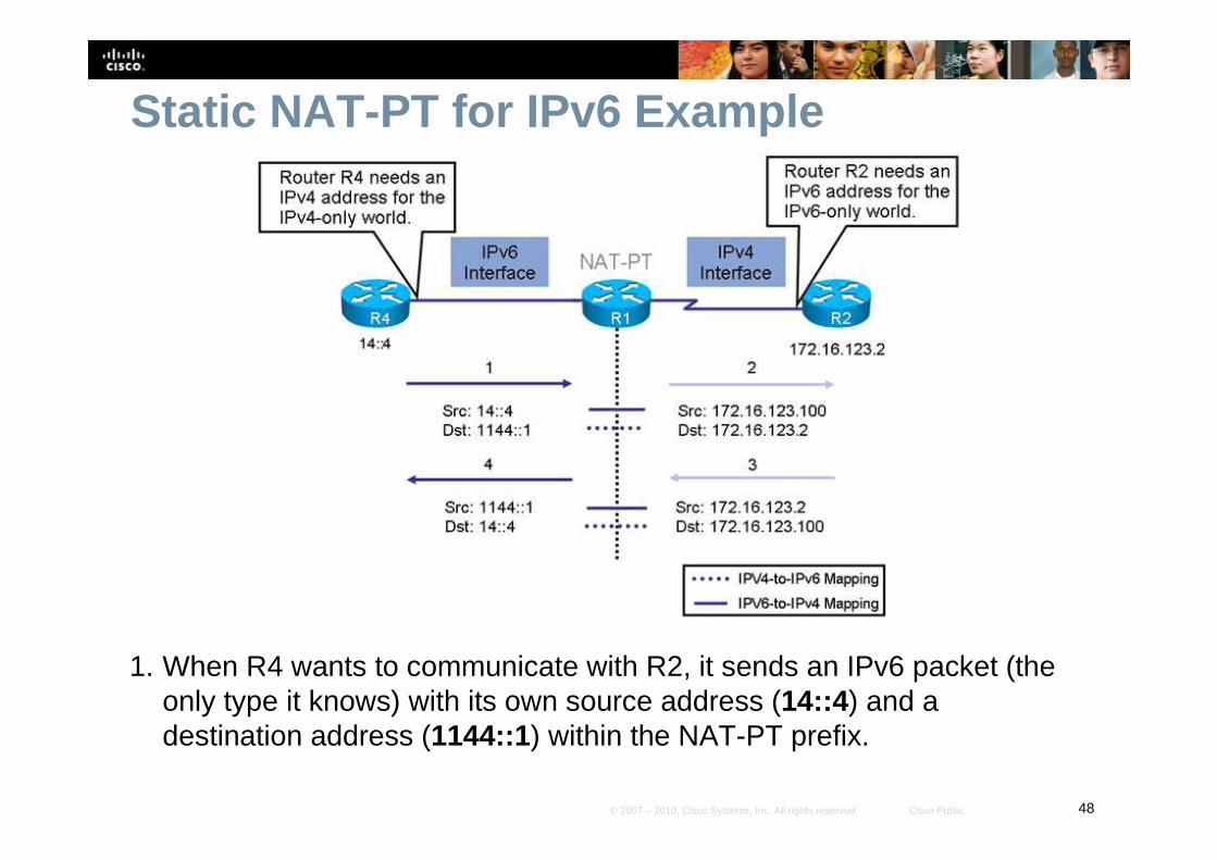
1. When R4 wants to communicate with R2, it sends an IPv6 packet (the only type it knows) with its own source address (14::4) and a destination address (1144::1) within the NAT-PT prefix.
49© 2007 – 2010, Cisco Systems, Inc. All rights reserved. Cisco Public
Static NAT-PT for IPv6 Example
2. When R1 receives the IPv6 packet:• It looks for a static translation for the destination IPv6 address and if found, it
translates it to R2’s IPv4 address. • It also translates R4’s IPv6 source address (14::4) to 172.16.123.100.
50© 2007 – 2010, Cisco Systems, Inc. All rights reserved. Cisco Public
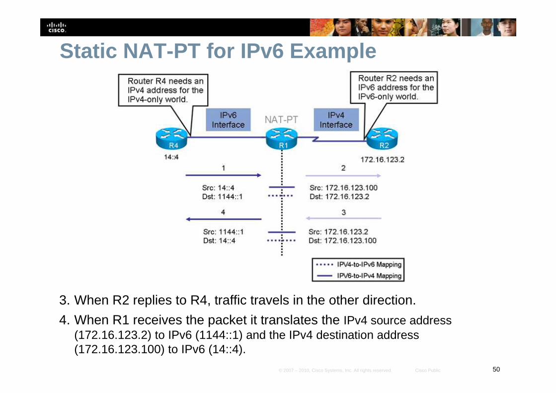
Static NAT-PT for IPv6 Example
3. When R2 replies to R4, traffic travels in the other direction.
4. When R1 receives the packet it translates the IPv4 source address (172.16.123.2) to IPv6 (1144::1) and the IPv4 destination address (172.16.123.100) to IPv6 (14::4).
51© 2007 – 2010, Cisco Systems, Inc. All rights reserved. Cisco Public
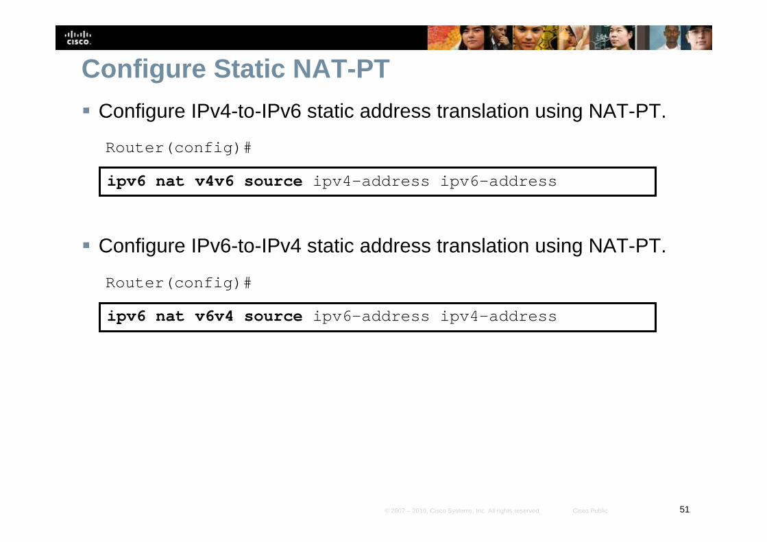
Configure Static NAT-PT
� Configure IPv4-to-IPv6 static address translation using NAT-PT.
Router(config)#
ipv6 nat v4v6 source ipv4-address ipv6-address
� Configure IPv6-to-IPv4 static address translation using NAT-PT.
Router(config)#
ipv6 nat v6v4 source ipv6-address ipv4-address
52© 2007 – 2010, Cisco Systems, Inc. All rights reserved. Cisco Public
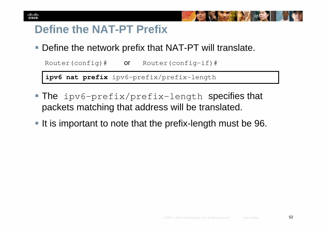
Define the NAT-PT Prefix
� Define the network prefix that NAT-PT will translate.
Router(config)# or Router(config-if)#
ipv6 nat prefix ipv6-prefix/prefix-length
� The ipv6-prefix/prefix-length specifies that packets matching that address will be translated.
� It is important to note that the prefix-length must be 96.
53© 2007 – 2010, Cisco Systems, Inc. All rights reserved. Cisco Public
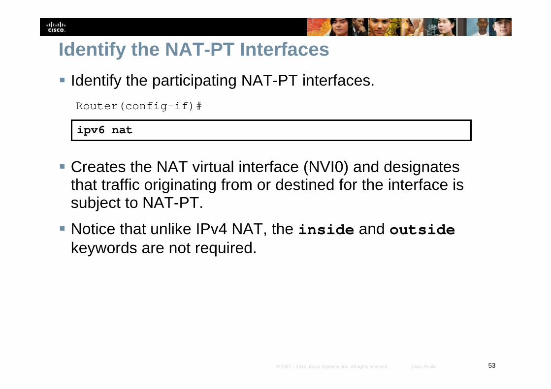
Identify the NAT-PT Interfaces
� Identify the participating NAT-PT interfaces.
Router(config-if)#
ipv6 nat
� Creates the NAT virtual interface (NVI0) and designates that traffic originating from or destined for the interface is subject to NAT-PT.
� Notice that unlike IPv4 NAT, the inside and outsidekeywords are not required.
54© 2007 – 2010, Cisco Systems, Inc. All rights reserved. Cisco Public
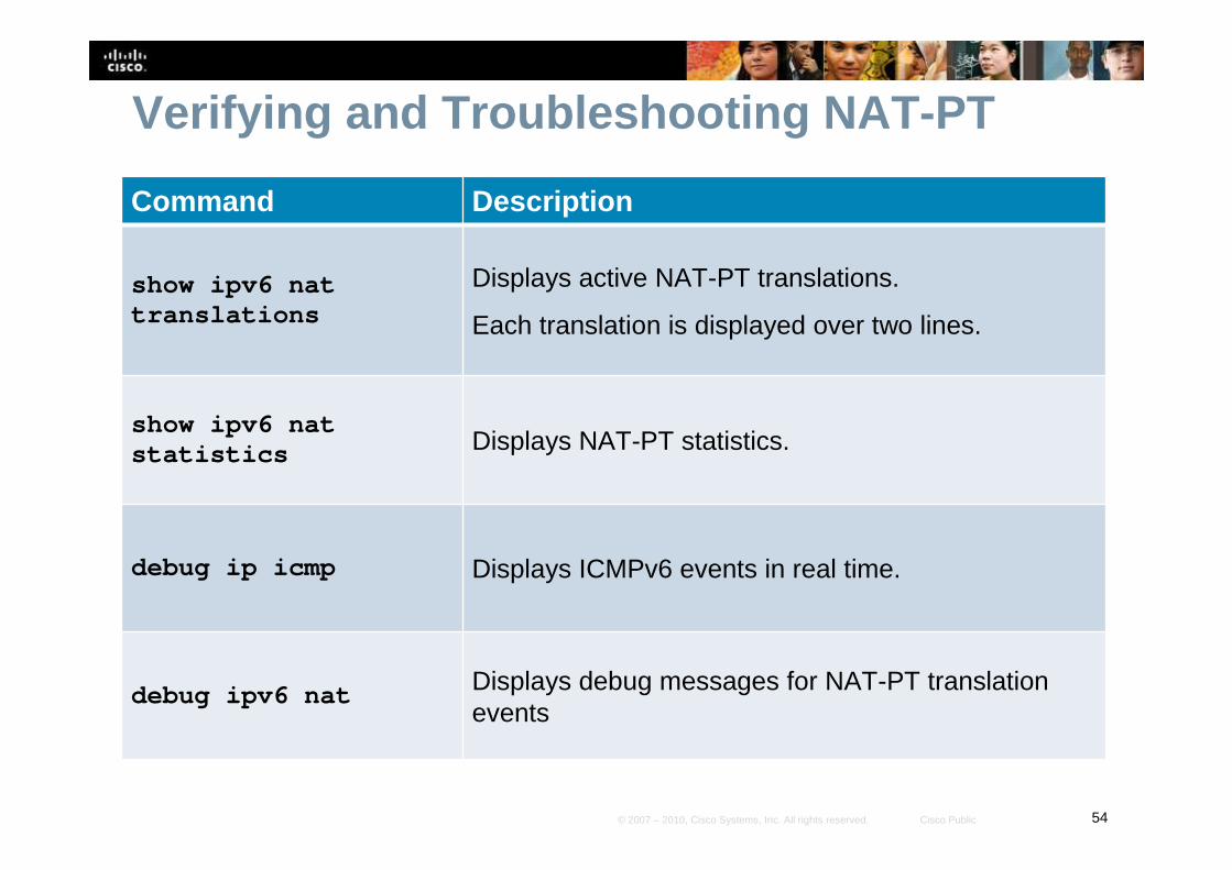
Verifying and Troubleshooting NAT-PT
Command Description
show ipv6 nat translations
Displays active NAT-PT translations.
Each translation is displayed over two lines.
show ipv6 nat statistics Displays NAT-PT statistics.
debug ip icmp Displays ICMPv6 events in real time.
debug ipv6 nat Displays debug messages for NAT-PT translation events

55© 2007 – 2010, Cisco Systems, Inc. All rights reserved. Cisco Public
Static NAT-PT Example
� In this example, R3 and R4 are IPv6-only devices, and R2 is an IPv4-only device.
� R1 is the NAT-PT router.
� R4 and R2 need to communicate, therefore two static translation entries are required in R1 to allow this bidirectional communication.
R1
R3
R4
172.16.123.0/24
.1 S0/0/0R2
S0/1/0
Lo102: 102::1/64
14::1/64
14::4/64.2
Lo103: 103::1/64
Lo104: 104::1/64
13::1/64
13::3/64
IPv6 RIP NAT-PT
IPv4 Only
Fa0/0
S0/0/0
Fa0/0
S0/0/0
56© 2007 – 2010, Cisco Systems, Inc. All rights reserved. Cisco Public
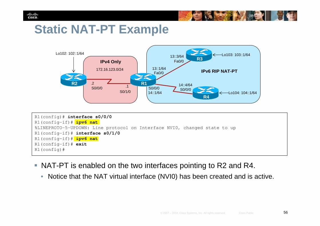
Static NAT-PT Example
� NAT-PT is enabled on the two interfaces pointing to R2 and R4.• Notice that the NAT virtual interface (NVI0) has been created and is active.
R1(config)# interface s0/0/0R1(config-if)# ipv6 nat%LINEPROTO-5-UPDOWN: Line protocol on Interface NVI 0, changed state to up R1(config-if)# interface s0/1/0R1(config-if)# ipv6 natR1(config-if)# exitR1(config)#
R1
R3
R4
172.16.123.0/24
.1 S0/0/0R2
S0/1/0
Lo102: 102::1/64
14::1/64
14::4/64.2
Lo103: 103::1/64
Lo104: 104::1/64
13::1/64
13::3/64
IPv6 RIP NAT-PT
IPv4 Only
Fa0/0
S0/0/0
Fa0/0
S0/0/0
57© 2007 – 2010, Cisco Systems, Inc. All rights reserved. Cisco Public
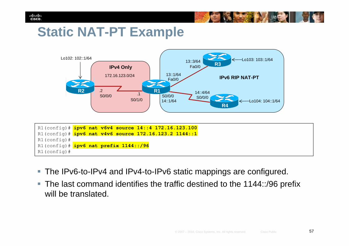
Static NAT-PT Example
� The IPv6-to-IPv4 and IPv4-to-IPv6 static mappings are configured.
� The last command identifies the traffic destined to the 1144::/96 prefix will be translated.
R1(config)# ipv6 nat v6v4 source 14::4 172.16.123.100R1(config)# ipv6 nat v4v6 source 172.16.123.2 1144::1R1(config)# R1(config)# ipv6 nat prefix 1144::/96R1(config)#
R1
R3
R4
172.16.123.0/24
.1 S0/0/0R2
S0/1/0
Lo102: 102::1/64
14::1/64
14::4/64.2
Lo103: 103::1/64
Lo104: 104::1/64
13::1/64
13::3/64
IPv6 RIP NAT-PT
IPv4 Only
Fa0/0
S0/0/0
Fa0/0
S0/0/0
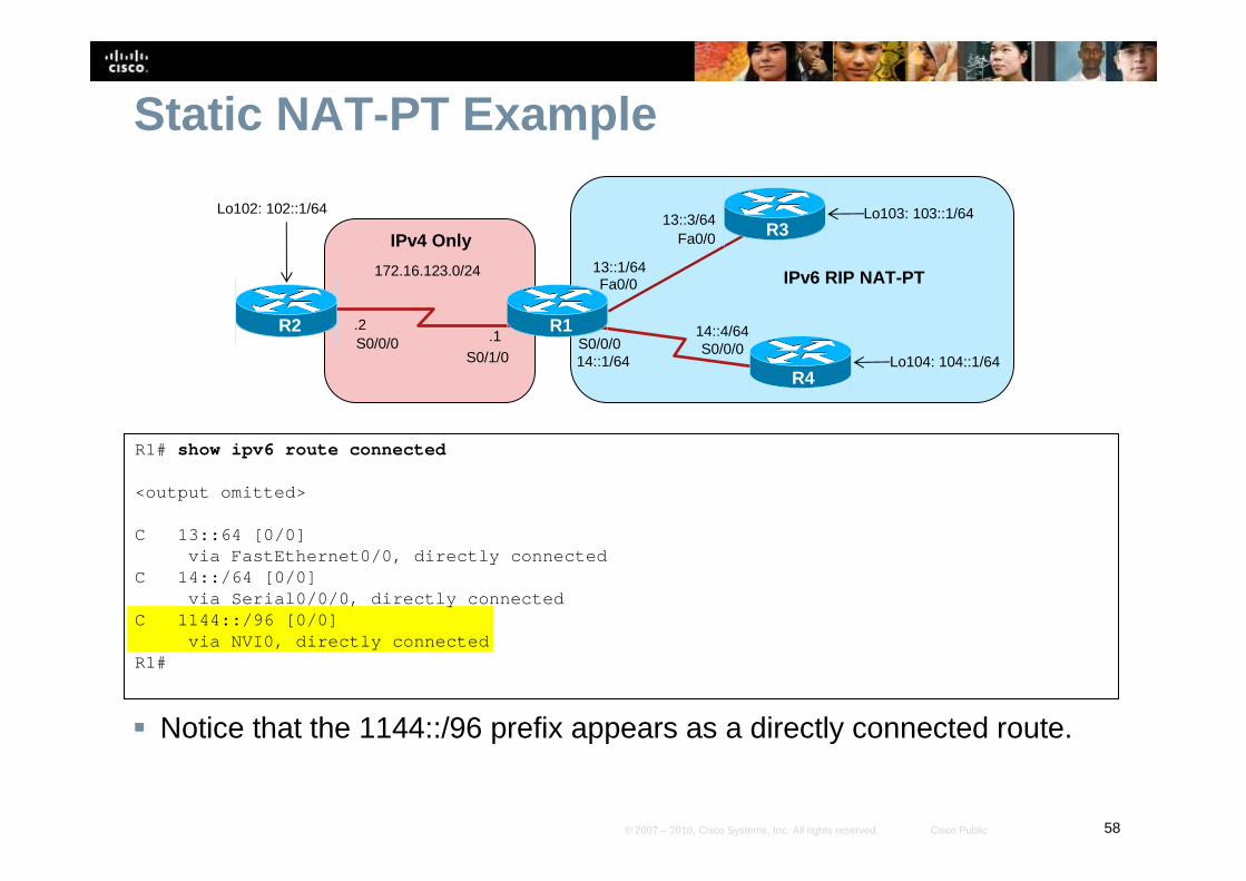
58© 2007 – 2010, Cisco Systems, Inc. All rights reserved. Cisco Public
Static NAT-PT Example
� Notice that the 1144::/96 prefix appears as a directly connected route.
R1# show ipv6 route connected
<output omitted>
C 13::64 [0/0]via FastEthernet0/0, directly connected
C 14::/64 [0/0]via Serial0/0/0, directly connected
C 1144::/96 [0/0]via NVI0, directly connected
R1#
R1
R3
R4
172.16.123.0/24
.1 S0/0/0R2
S0/1/0
Lo102: 102::1/64
14::1/64
14::4/64.2
Lo103: 103::1/64
Lo104: 104::1/64
13::1/64
13::3/64
IPv6 RIP NAT-PT
IPv4 Only
Fa0/0
S0/0/0
Fa0/0
S0/0/0
59© 2007 – 2010, Cisco Systems, Inc. All rights reserved. Cisco Public
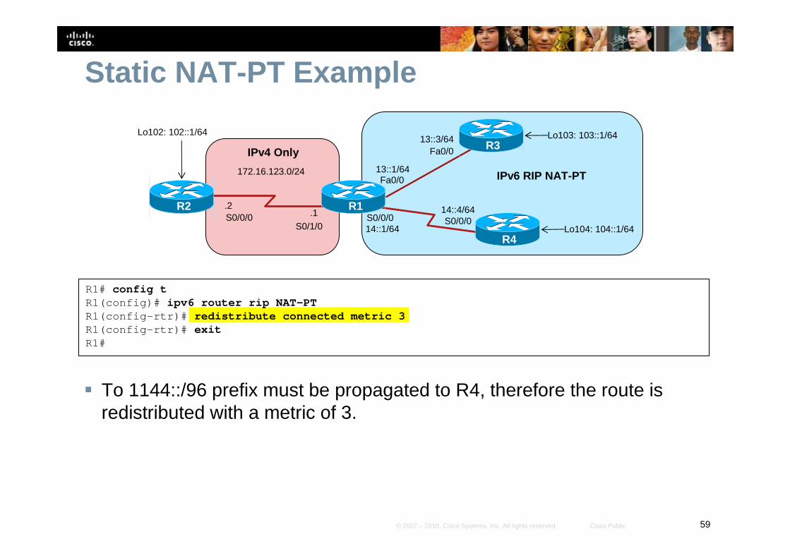
Static NAT-PT Example
� To 1144::/96 prefix must be propagated to R4, therefore the route is redistributed with a metric of 3.
R1# config tR1(config)# ipv6 router rip NAT-PTR1(config-rtr)# redistribute connected metric 3R1(config-rtr)# exitR1#
R1
R3
R4
172.16.123.0/24
.1 S0/0/0R2
S0/1/0
Lo102: 102::1/64
14::1/64
14::4/64.2
Lo103: 103::1/64
Lo104: 104::1/64
13::1/64
13::3/64
IPv6 RIP NAT-PT
IPv4 Only
Fa0/0
S0/0/0
Fa0/0
S0/0/0
60© 2007 – 2010, Cisco Systems, Inc. All rights reserved. Cisco Public
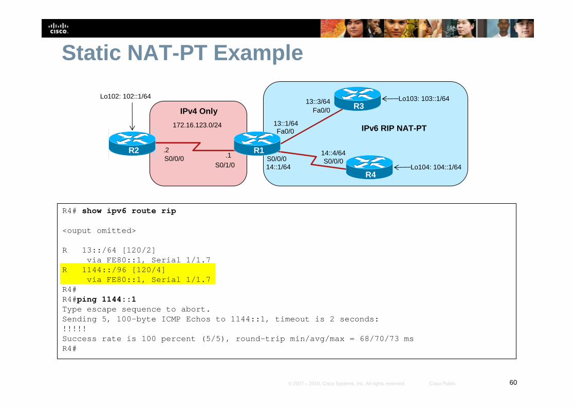
R4# show ipv6 route rip
<ouput omitted>
R 13::/64 [120/2]via FE80::1, Serial 1/1.7
R 1144::/96 [120/4]via FE80::1, Serial 1/1.7
R4#R4#ping 1144::1Type escape sequence to abort.Sending 5, 100-byte ICMP Echos to 1144::1, timeout is 2 seconds:!!!!!Success rate is 100 percent (5/5), round-trip min/a vg/max = 68/70/73 msR4#
Static NAT-PT Example
R1
R3
R4
172.16.123.0/24
.1 S0/0/0R2
S0/1/0
Lo102: 102::1/64
14::1/64
14::4/64.2
Lo103: 103::1/64
Lo104: 104::1/64
13::1/64
13::3/64
IPv6 RIP NAT-PT
IPv4 Only
Fa0/0
S0/0/0
Fa0/0
S0/0/0
61© 2007 – 2010, Cisco Systems, Inc. All rights reserved. Cisco Public
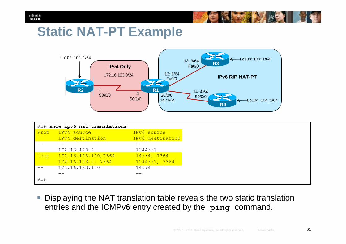
Static NAT-PT Example
� Displaying the NAT translation table reveals the two static translation entries and the ICMPv6 entry created by the ping command.
R1# show ipv6 nat translationsProt IPv4 source IPv6 source
IPv4 destination IPv6 destination—- —- —-
172.16.123.2 1144::1icmp 172.16.123.100,7364 14::4, 7364
172.16.123.2, 7364 1144::1, 7364—- 172.16.123.100 14::4
—- —-R1#
R1
R3
R4
172.16.123.0/24
.1 S0/0/0R2
S0/1/0
Lo102: 102::1/64
14::1/64
14::4/64.2
Lo103: 103::1/64
Lo104: 104::1/64
13::1/64
13::3/64
IPv6 RIP NAT-PT
IPv4 Only
Fa0/0
S0/0/0
Fa0/0
S0/0/0
62© 2007 – 2010, Cisco Systems, Inc. All rights reserved. Cisco Public
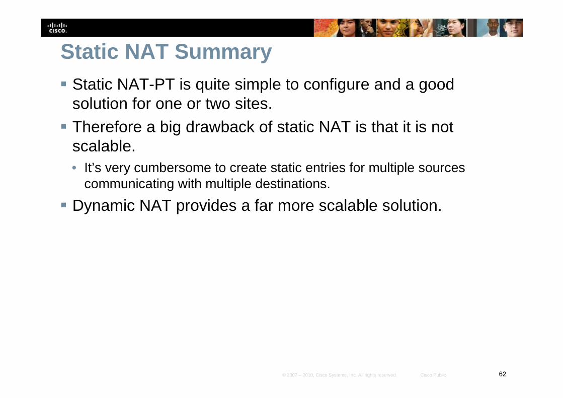
Static NAT Summary� Static NAT-PT is quite simple to configure and a good
solution for one or two sites.
� Therefore a big drawback of static NAT is that it is not scalable.• It’s very cumbersome to create static entries for multiple sources
communicating with multiple destinations.
� Dynamic NAT provides a far more scalable solution.

63© 2007 – 2010, Cisco Systems, Inc. All rights reserved. Cisco Public
Dynamic NAT-PT for IPv6� With dynamic NAT-PT, addresses are allocated from an
address pool, the same as is done with IPv4 dynamic NAT. • Again, the commands have similar syntax to their IPv4 NAT.
� When the NAT-PT router receives a packet with an IPv6 destination address of an arbitrarily assigned 96-bit prefix (the NAT-PT prefix), it translates the IPv6 packet to an IPv4 address from an address pool.
64© 2007 – 2010, Cisco Systems, Inc. All rights reserved. Cisco Public
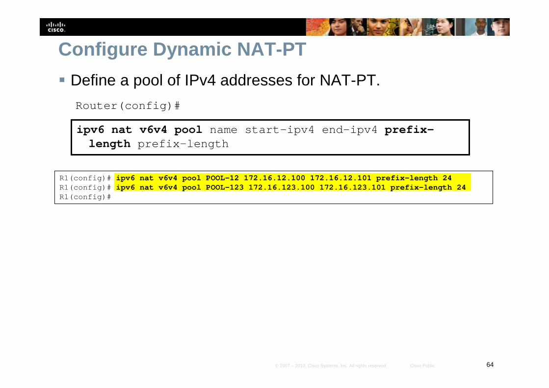
Configure Dynamic NAT-PT
� Define a pool of IPv4 addresses for NAT-PT.
Router(config)#
ipv6 nat v6v4 pool name start-ipv4 end-ipv4 prefix-length prefix-length
R1(config)# ipv6 nat v6v4 pool POOL-12 172.16.12.100 172.16.12.101 prefix-length 24R1(config)# ipv6 nat v6v4 pool POOL-123 172.16.123.100 172.16.123.101 prefix-length 24R1(config)#
65© 2007 – 2010, Cisco Systems, Inc. All rights reserved. Cisco Public
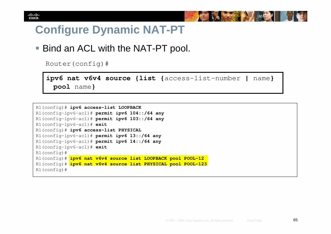
Configure Dynamic NAT-PT
� Bind an ACL with the NAT-PT pool.
Router(config)#
ipv6 nat v6v4 source {list {access-list-number | name} pool name}
R1(config)# ipv6 access-list LOOPBACKR1(config-ipv6-acl)# permit ipv6 104::/64 anyR1(config-ipv6-acl)# permit ipv6 103::/64 anyR1(config-ipv6-acl)# exitR1(config)# ipv6 access-list PHYSICALR1(config-ipv6-acl)# permit ipv6 13::/64 anyR1(config-ipv6-acl)# permit ipv6 14::/64 anyR1(config-ipv6-acl)# exitR1(config)#R1(config)# ipv6 nat v6v4 source list LOOPBACK pool POOL-12R1(config)# ipv6 nat v6v4 source list PHYSICAL pool POOL-123R1(config)#
66© 2007 – 2010, Cisco Systems, Inc. All rights reserved. Cisco Public
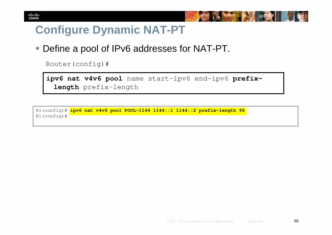
Configure Dynamic NAT-PT
� Define a pool of IPv6 addresses for NAT-PT.
Router(config)#
ipv6 nat v4v6 pool name start-ipv6 end-ipv6 prefix-length prefix-length
R1(config)# ipv6 nat v4v6 pool POOL-1144 1144::1 1144::2 prefix-length 96R1(config)#
67© 2007 – 2010, Cisco Systems, Inc. All rights reserved. Cisco Public
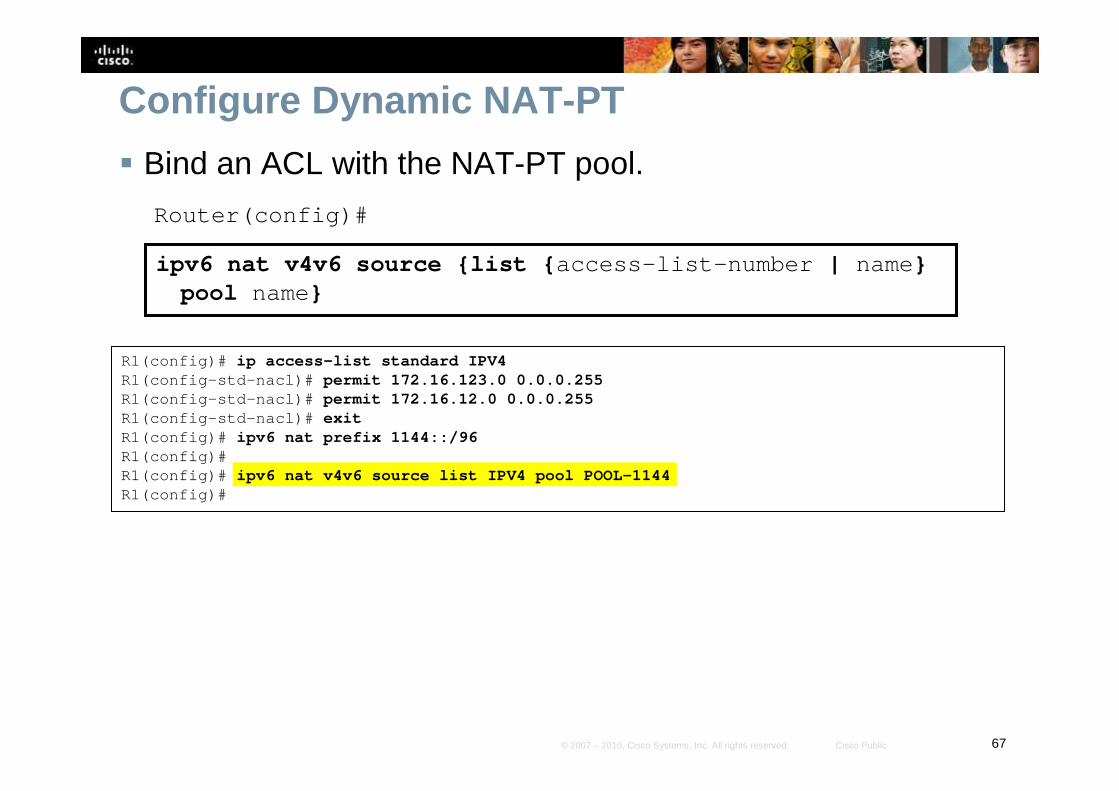
Configure Dynamic NAT-PT
� Bind an ACL with the NAT-PT pool.
Router(config)#
ipv6 nat v4v6 source {list {access-list-number | name} pool name}
R1(config)# ip access-list standard IPV4R1(config-std-nacl)# permit 172.16.123.0 0.0.0.255R1(config-std-nacl)# permit 172.16.12.0 0.0.0.255R1(config-std-nacl)# exitR1(config)# ipv6 nat prefix 1144::/96R1(config)#R1(config)# ipv6 nat v4v6 source list IPV4 pool POOL-1144R1(config)#