Embed Size (px)
Citation preview
©2013 PACE Inc., Southern Pines North Carolina, All Rights Reserved. www.paceworldwide.com Page 1
IR 3000 BGA Rework Station
Operation and Maintenance Manual
Manual Number 5050-0569 REV 4-10-13
PACE IR 3000
©2013 PACE Inc., Southern Pines North Carolina, All Rights Reserved. www.paceworldwide.com Page 2
Table of Contents
Packing Contents, Standard Items .................................. 3 Specifications .................................................................. 3 Parts Identification ........................................................... 4 Safety Information ........................................................... 5 Features .......................................................................... 6 Set-Up
Connect ................................................................ 6 Start up ................................................................. 6 Inserting/changing vacuum pick ............................ 6 Software set up screen features ........................... 7 Alignment screen features .................................... 8 Production screen features ................................... 9 Production Mode Record Manager ....................... 9 Profile development screen features ................... 10 Profile Development Profile manager ................. 11 Inspection screen features .................................. 12 Prism Calibration................................................. 15 Adjusting the Prism ............................................. 16 Operation ............................................................ 17 Installation. .......................................................... 17 Component removal ........................................... 18 Profile development ............................................ 19
Helpful Tips.................................................................... 20 Maintenance .................................................................. 22 Regulation ..................................................................... 30 Service and Warranty .................................................... 31 Contact Information ....................................................... 32
©2013 PACE Inc., Southern Pines North Carolina, All Rights Reserved. www.paceworldwide.com Page 3
Packing Contents, Standard Items
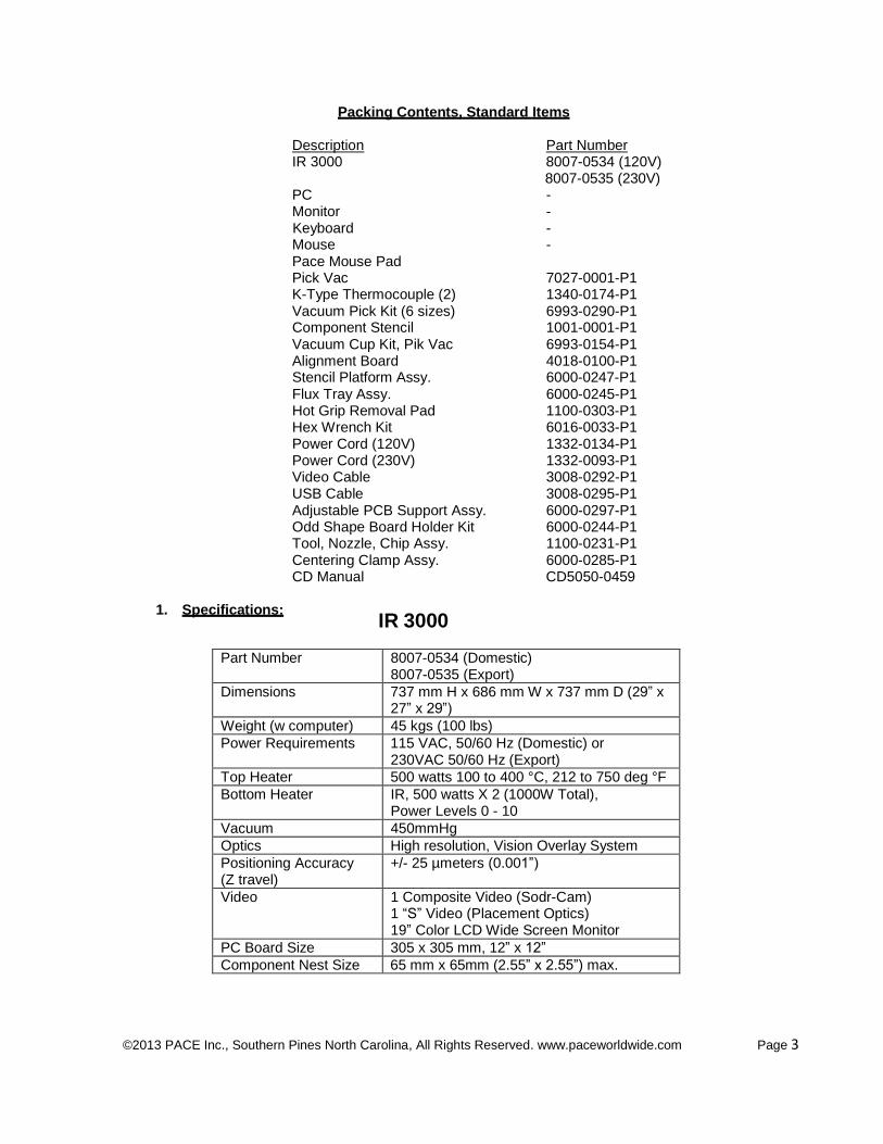
Description Part Number IR 3000 8007-0534 (120V)
8007-0535 (230V) PC - Monitor - Keyboard - Mouse - Pace Mouse Pad Pick Vac 7027-0001-P1 K-Type Thermocouple (2) 1340-0174-P1 Vacuum Pick Kit (6 sizes) 6993-0290-P1 Component Stencil 1001-0001-P1 Vacuum Cup Kit, Pik Vac 6993-0154-P1 Alignment Board 4018-0100-P1 Stencil Platform Assy. 6000-0247-P1 Flux Tray Assy. 6000-0245-P1 Hot Grip Removal Pad 1100-0303-P1 Hex Wrench Kit 6016-0033-P1 Power Cord (120V) 1332-0134-P1 Power Cord (230V) 1332-0093-P1 Video Cable 3008-0292-P1 USB Cable 3008-0295-P1 Adjustable PCB Support Assy. 6000-0297-P1 Odd Shape Board Holder Kit 6000-0244-P1 Tool, Nozzle, Chip Assy. 1100-0231-P1 Centering Clamp Assy. 6000-0285-P1 CD Manual CD5050-0459
1. Specifications:
IR 3000
Part Number 8007-0534 (Domestic) 8007-0535 (Export)
Dimensions 737 mm H x 686 mm W x 737 mm D (29” x 27” x 29”)
Weight (w computer) 45 kgs (100 lbs)
Power Requirements 115 VAC, 50/60 Hz (Domestic) or 230VAC 50/60 Hz (Export)
Top Heater 500 watts 100 to 400 °C, 212 to 750 deg °F
Bottom Heater IR, 500 watts X 2 (1000W Total), Power Levels 0 - 10
Vacuum 450mmHg
Optics High resolution, Vision Overlay System
Positioning Accuracy (Z travel)
+/- 25 µmeters (0.001”)
Video 1 Composite Video (Sodr-Cam) 1 “S” Video (Placement Optics) 19” Color LCD Wide Screen Monitor
PC Board Size 305 x 305 mm, 12” x 12”
Component Nest Size 65 mm x 65mm (2.55” x 2.55”) max.
©2013 PACE Inc., Southern Pines North Carolina, All Rights Reserved. www.paceworldwide.com Page 4
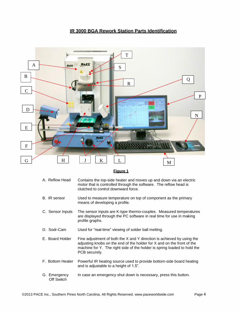
IR 3000 BGA Rework Station Parts Identification
T
A
S
B Q
R
C
P
D
N
E
F
G H J K L M
A. Reflow Head
Figure 1 Contains the top-side heater and moves up and down via an electric
motor that is controlled through the software. The reflow head is clutched to control downward force.
B. IR sensor
Used to measure temperature on top of component as the primary means of developing a profile.
C. Sensor Inputs
The sensor inputs are K-type thermo-couples. Measured temperatures are displayed through the PC software in real time for use in making profile graphs.
D. Sodr-Cam
Used for “real-time” viewing of solder ball melting.
E. Board Holder
Fine adjustment of both the X and Y direction is achieved by using the adjusting knobs on the end of the holder for X and on the front of the machine for Y. The right side of the holder is spring loaded to hold the PCB securely.
F. Bottom Heater
Powerful IR heating source used to provide bottom-side board heating and is adjustable to a height of 1.5”.
G. Emergency
In case an emergency shut down is necessary, press this button. Off Switch

©2013 PACE Inc., Southern Pines North Carolina, All Rights Reserved. www.paceworldwide.com Page 5
H. Optics Housing Contains the camera and beam splitter (prism). The housing extends and retracts automatically during operation and the lights for the optics will turn on/off automatically when the housing is extended/retracted.
J. Micrometer Precision “x” and “y” axis board alignment micrometer dials for accurate
Dials positioning and aligning of component to PCB.
K. Bottom Heater Used to adjust the height of the heater with respect to Adjustment Knob Height Adjust the bottom-side board surface. Can be raised to a maximum of 1.5”
height.
L. On / Off Switch Used to turn the system on or off. When turning off the system, always turn off the PC using the windows interface first. When starting the system, always turn on the IR 3000 before starting the PC software.
M. Keyboard Used to enter information into software.
N. Mouse Used to enter information into software.
P. Display Monitor Displays PC software.
Q. Cooling Fan The component and PCB are cooled by the cooling fan, and can be
activated automatically after the reflow cycle is complete or operated manually.
R. Aperture Used to change the size and/or shape of IR pattern to the size of the
Adjustment component being reworked. Knobs
S. Theta Dial Enables 360 degree rotation of component for alignment to PCB.
T. IR Heater Indicator Neon heater lamp indicates topside IR heater activity.
2. Safety Information
a. Do not contact the Heater or its peripheral parts during operation. b. Once turned off, let the unit cool completely before contacting. They are hot, you will get
burned. c. When using fluxes, use fume extraction equipment or use in a well-ventilated area to
minimize operator exposure to fumes. d. Do not use near combustible vapors. e. Do not leave the equipment unattended when in use. f. Do not open rear panel without disconnecting the main power cable.
3. Features
a. The IR 3000 is ideal for post assembly rework, repair, and low volume/short run production operations. The IR 3000 can remove and install PBGAs, CSPs, FCs, LGAs, LCC’s and other SMDs.
©2013 PACE Inc., Southern Pines North Carolina, All Rights Reserved. www.paceworldwide.com Page 6
b. Featuring unparalleled thermal performance, PACE BGA Rework Stations flexibility and state of the art process software means no other system is easier to use. The IR 3000 is a PC driven, semi-automated system that requires a Pentium ® 4 PC featuring Windows XP® Professional OS. The unique standard software package offers much more than just an operator interface. PACE BGA Rework Stations advanced vision and placement system is highly accurate and can quickly magnify even the smallest components for easy alignment. The IR 3000 uses a combination of IR top heating coupled with powerful IR bottom heating for an effective, repeatable heating process.
c. Economical and easy to use, PACE BGA Rework Systems deliver high-end BGA/CSP functionality, moving far beyond expensive, bulky rework machines by offering unparalleled performance at an affordable price.
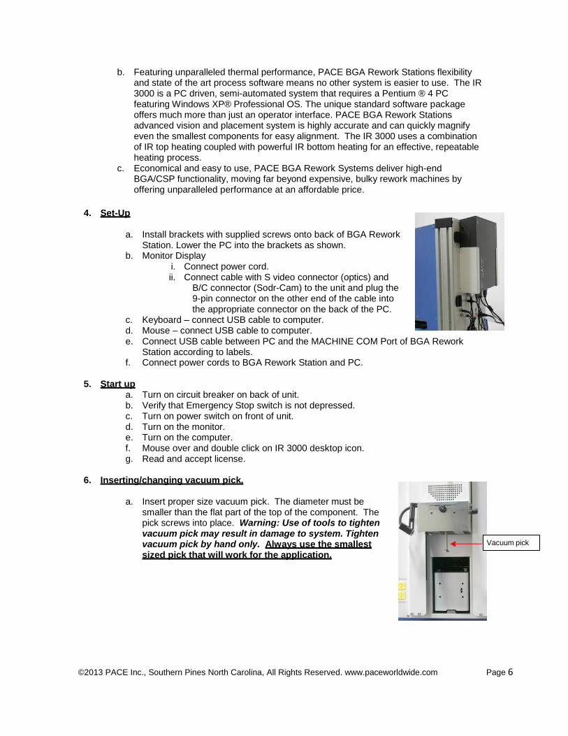
4. Set-Up
a. Install brackets with supplied screws onto back of BGA Rework
Station. Lower the PC into the brackets as shown. b. Monitor Display
i. Connect power cord. ii. Connect cable with S video connector (optics) and
B/C connector (Sodr-Cam) to the unit and plug the 9-pin connector on the other end of the cable into the appropriate connector on the back of the PC.
c. Keyboard – connect USB cable to computer. d. Mouse – connect USB cable to computer. e. Connect USB cable between PC and the MACHINE COM Port of BGA Rework
Station according to labels. f. Connect power cords to BGA Rework Station and PC.
5. Start up
a. Turn on circuit breaker on back of unit. b. Verify that Emergency Stop switch is not depressed. c. Turn on power switch on front of unit. d. Turn on the monitor. e. Turn on the computer. f. Mouse over and double click on IR 3000 desktop icon. g. Read and accept license.
6. Inserting/changing vacuum pick.
a. Insert proper size vacuum pick. The diameter must be smaller than the flat part of the top of the component. The pick screws into place. Warning: Use of tools to tighten vacuum pick may result in damage to system. Tighten vacuum pick by hand only. Always use the smallest sized pick that will work for the application.
Vacuum pick
©2013 PACE Inc., Southern Pines North Carolina, All Rights Reserved. www.paceworldwide.com Page 7
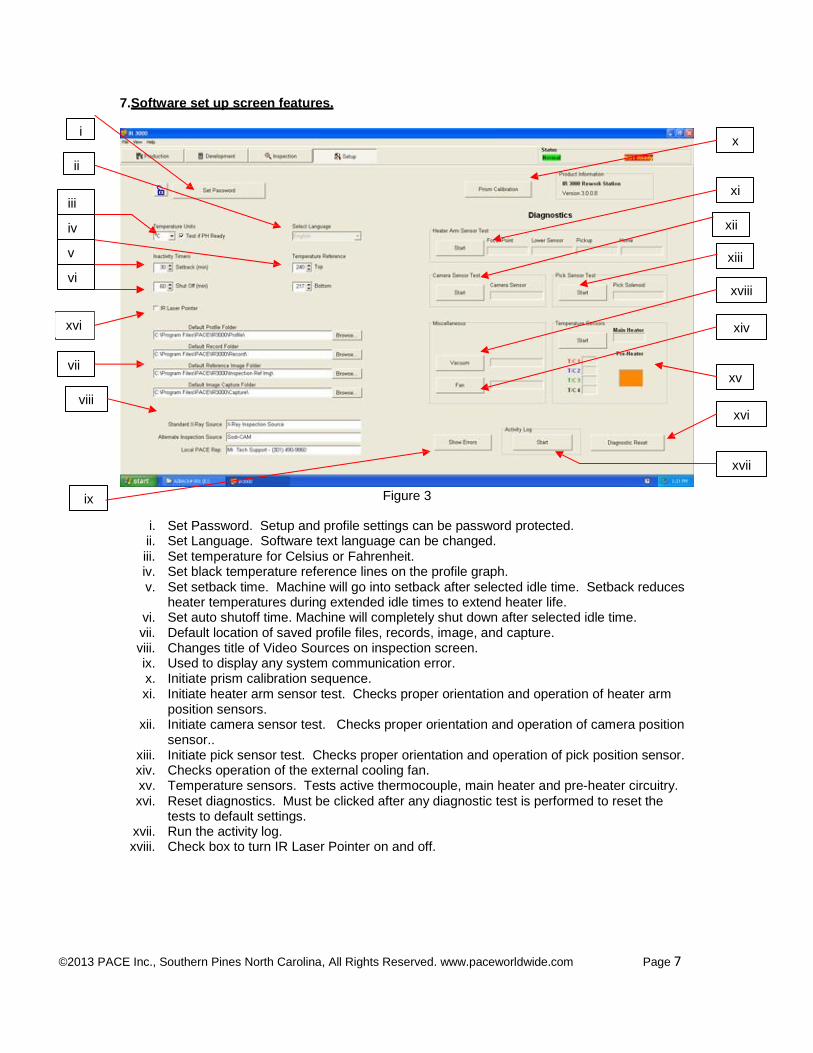
7. Software set up screen features.
i
ii
iii
iv
v
vi
x
xi
xii
xiii
xviii
xvi
xiv
vii
viii
xv
xvi
ix Figure 3
i. Set Password. Setup and profile settings can be password protected. ii. Set Language. Software text language can be changed. iii. Set temperature for Celsius or Fahrenheit. iv. Set black temperature reference lines on the profile graph. v. Set setback time. Machine will go into setback after selected idle time. Setback reduces
heater temperatures during extended idle times to extend heater life. vi. Set auto shutoff time. Machine will completely shut down after selected idle time. vii. Default location of saved profile files, records, image, and capture. viii. Changes title of Video Sources on inspection screen. ix. Used to display any system communication error. x. Initiate prism calibration sequence. xi. Initiate heater arm sensor test. Checks proper orientation and operation of heater arm
position sensors. xii. Initiate camera sensor test. Checks proper orientation and operation of camera position
sensor.. xiii. Initiate pick sensor test. Checks proper orientation and operation of pick position sensor. xiv. Checks operation of the external cooling fan. xv. Temperature sensors. Tests active thermocouple, main heater and pre-heater circuitry. xvi. Reset diagnostics. Must be clicked after any diagnostic test is performed to reset the
tests to default settings. xvii. Run the activity log. xviii. Check box to turn IR Laser Pointer on and off.
xvii
©2013 PACE Inc., Southern Pines North Carolina, All Rights Reserved. www.paceworldwide.com Page 8
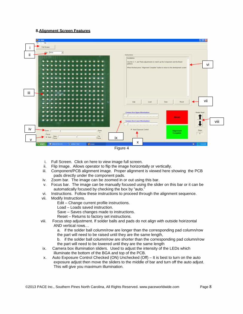
8. Alignment Screen Features
i
ii
vi
iii
vii
iv
v ix x
Figure 4
viii
i. Full Screen. Click on here to view image full screen. ii. Flip Image. Allows operator to flip the image horizontally or vertically. iii. Component/PCB alignment image. Proper alignment is viewed here showing the PCB
pads directly under the component pads. iv. Zoom bar. The image can be zoomed in or out using this bar. v. Focus bar. The image can be manually focused using the slider on this bar or it can be
automatically focused by checking the box by “auto.” vi. Instructions. Follow these instructions to proceed through the alignment sequence. vii. Modify Instructions.
Edit – Change current profile instructions. Load – Loads saved instruction. Save – Saves changes made to instructions. Reset – Returns to factory set instructions.
viii. Focus step adjustment. If solder balls and pads do not align with outside hoirizontal AND vertical rows…
a. if the solder ball column/row are longer than the corresponding pad column/row the part will need to be raised until they are the same length, b. if the solder ball column/row are shorter than the corresponding pad column/row the part will need to be lowered until they are the same length
ix. Camera box illumination sliders. Used to adjust the intensity of the LEDs which illuminate the bottom of the BGA and top of the PCB.
x. Auto Exposure Control Checked (ON) Unchecked (Off) – It is best to turn on the auto exposure adjust then move the sliders to the middle of bar and turn off the auto adjust. This will give you maximum illumination.
©2013 PACE Inc., Southern Pines North Carolina, All Rights Reserved. www.paceworldwide.com Page 9
iii
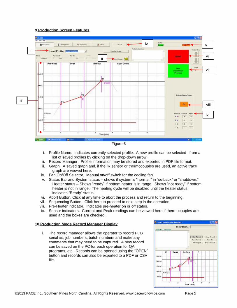
9. Production Screen Features
iv v
i
ii vi
vii
viii
ix
Figure 6
i. Profile Name. Indicates currently selected profile. A new profile can be selected from a list of saved profiles by clicking on the drop-down arrow.
ii. Record Manager. Profile information may be stored and exported in PDF file format.
iii. Graph. A saved graph and, if the IR sensor or thermocouples are used, an active trace graph are viewed here.
iv. Fan On/Off Selector. Manual on/off switch for the cooling fan. v. Status Bar and System status – shows if system is “normal,” in “setback” or “shutdown.”
Heater status – Shows “ready” if bottom heater is in range. Shows “not ready” if bottom heater is not in range. The heating cycle will be disabled until the heater status indicates “Ready” status.
vi. Abort Button. Click at any time to abort the process and return to the beginning. vii. Sequencing Button. Click here to proceed to next step in the operation. viii. Pre-Heater indicator. Indicates pre-heater on or off status. ix. Sensor indicators. Current and Peak readings can be viewed here if thermocouples are
used and the boxes are checked.
10. Production Mode Record Manager Display
i. The record manager allows the operator to record PCB serial #s, job numbers, batch numbers and make any comments that may need to be captured. A new record can be saved on the PC for each operation for QA programs, etc. Records can be opened using the “OPEN” button and records can also be exported to a PDF or CSV file.
©2013 PACE Inc., Southern Pines North Carolina, All Rights Reserved. www.paceworldwide.com Page 10
i
11. Profile Development Screen features vii
iv v
xii xi
vi
ix ii
viii
iii
x
Figure 7
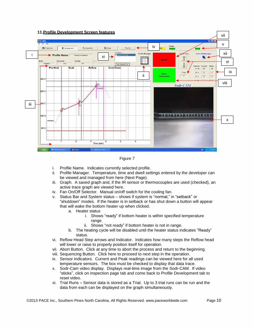
i. Profile Name. Indicates currently selected profile. ii. Profile Manager. Temperature, time and dwell settings entered by the developer can
be viewed and managed from here (Next Page). iii. Graph. A saved graph and, if the IR sensor or thermocouples are used (checked), an
active trace graph are viewed here. iv. Fan On/Off Selector. Manual on/off switch for the cooling fan. v. Status Bar and System status – shows if system is “normal,” in “setback” or
“shutdown” modes. If the heater is in setback or has shut down a button will appear that will wake the bottom heater up when clicked.
a. Heater status i. Shows “ready” if bottom heater is within specified temperature
range. ii. Shows “not ready” if bottom heater is not in range.
b. The heating cycle will be disabled until the heater status indicates “Ready” status.
vi. Reflow Head Step arrows and Indicator. Indicates how many steps the Reflow head will lower or raise to properly position itself for operation.
vii. Abort Button. Click at any time to abort the process and return to the beginning. viii. Sequencing Button. Click here to proceed to next step in the operation. ix. Sensor indicators. Current and Peak readings can be viewed here for all used
temperature sensors. The box must be checked to display that data trace. x. Sodr-Cam video display. Displays real-time image from the Sodr-CAM. If video
“sticks”, click on inspection page tab and come back to Profile Development tab to reset video.
xi. Trial Runs – Sensor data is stored as a Trial. Up to 3 trial runs can be run and the data from each can be displayed on the graph simultaneously.
©2013 PACE Inc., Southern Pines North Carolina, All Rights Reserved. www.paceworldwide.com Page 11
xii. Sodr-Cam Manager – Opens a control box where the focus, zoom, and auto exposure can be controlled for the Sodr-Cam.
12. Development Mode Profile Manager Screen Features of the IR 3000
i
ii
xi
x
ix
iii
viii
iv v vi vii
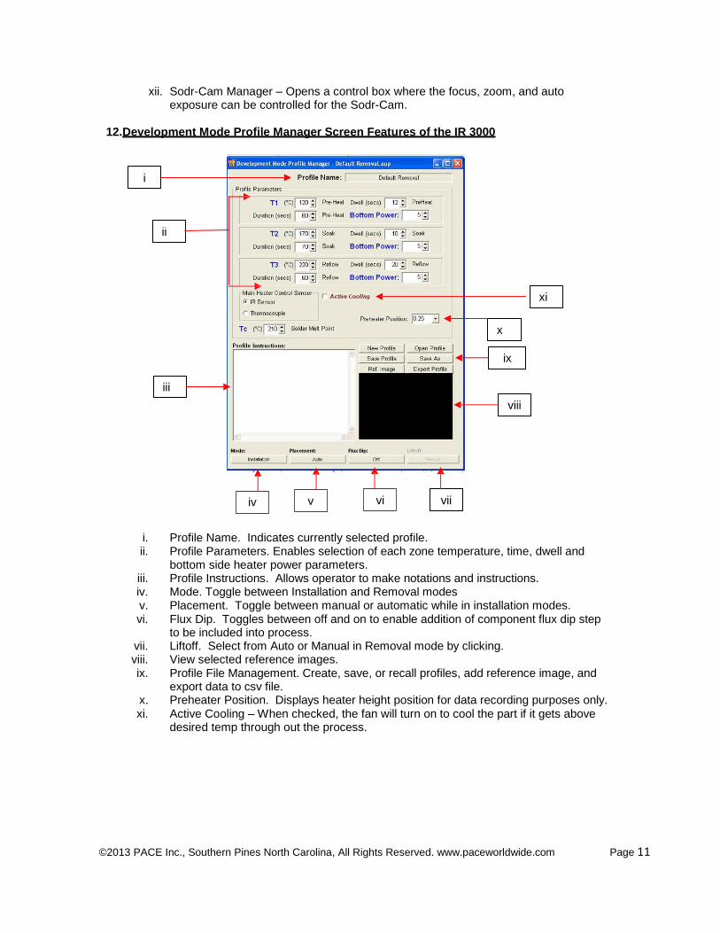
i. Profile Name. Indicates currently selected profile. ii. Profile Parameters. Enables selection of each zone temperature, time, dwell and
bottom side heater power parameters. iii. Profile Instructions. Allows operator to make notations and instructions. iv. Mode. Toggle between Installation and Removal modes v. Placement. Toggle between manual or automatic while in installation modes. vi. Flux Dip. Toggles between off and on to enable addition of component flux dip step
to be included into process. vii. Liftoff. Select from Auto or Manual in Removal mode by clicking. viii. View selected reference images. ix. Profile File Management. Create, save, or recall profiles, add reference image, and
export data to csv file. x. Preheater Position. Displays heater height position for data recording purposes only. xi. Active Cooling – When checked, the fan will turn on to cool the part if it gets above
desired temp through out the process.
©2013 PACE Inc., Southern Pines North Carolina, All Rights Reserved. www.paceworldwide.com Page 12
Ins
13. Inspection Screen Features – Image Capture Mode
i vi
iii
ii
v viii
vii Inspection Screen (Figure 8) iv
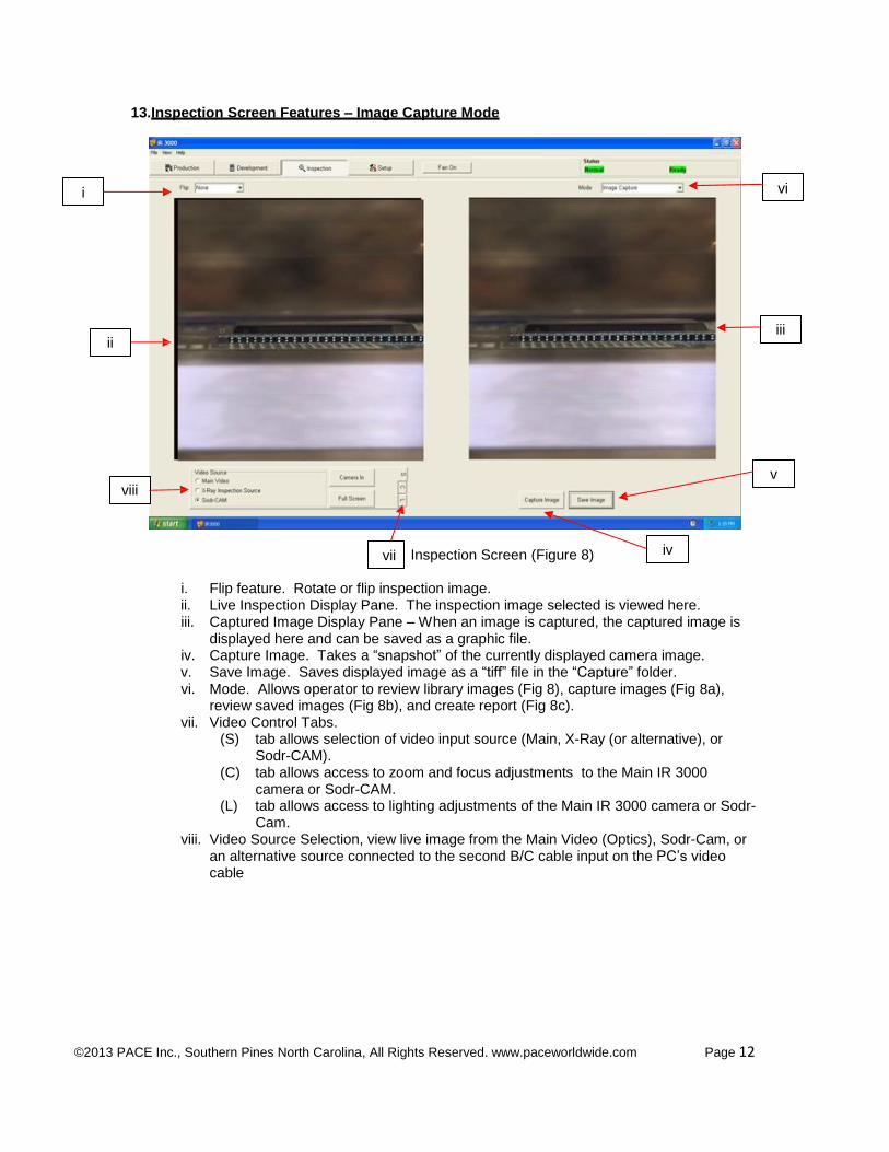
i. Flip feature. Rotate or flip inspection image. ii. Live Inspection Display Pane. The inspection image selected is viewed here. iii. Captured Image Display Pane – When an image is captured, the captured image is
displayed here and can be saved as a graphic file. iv. Capture Image. Takes a “snapshot” of the currently displayed camera image. v. Save Image. Saves displayed image as a “tiff” file in the “Capture” folder. vi. Mode. Allows operator to review library images (Fig 8), capture images (Fig 8a),
review saved images (Fig 8b), and create report (Fig 8c). vii. Video Control Tabs.
(S) tab allows selection of video input source (Main, X-Ray (or alternative), or Sodr-CAM).
(C) tab allows access to zoom and focus adjustments to the Main IR 3000 camera or Sodr-CAM.
(L) tab allows access to lighting adjustments of the Main IR 3000 camera or Sodr- Cam.
viii. Video Source Selection, view live image from the Main Video (Optics), Sodr-Cam, or an alternative source connected to the second B/C cable input on the PC’s video cable
©2013 PACE Inc., Southern Pines North Carolina, All Rights Reserved. www.paceworldwide.com Page 13
14. Inspection Screen Features (Review Images Mode)
i
ii
Review Saved Images & Refere-nce Image Modes Figure 8a
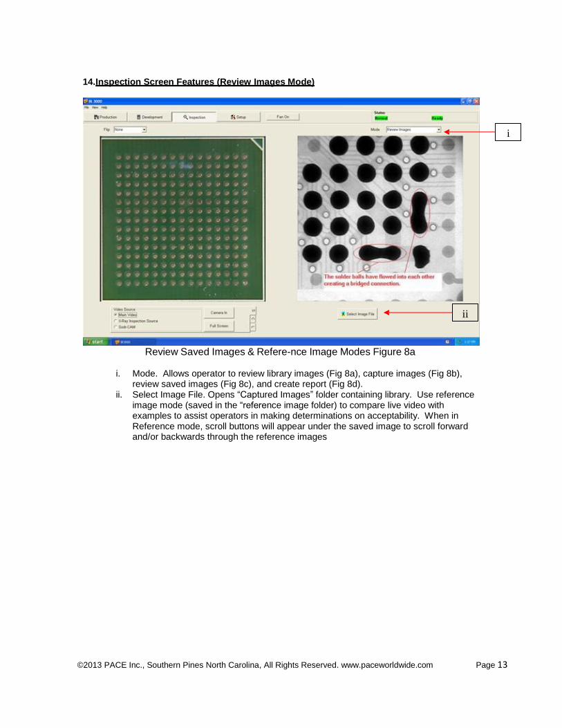
i. Mode. Allows operator to review library images (Fig 8a), capture images (Fig 8b),
review saved images (Fig 8c), and create report (Fig 8d). ii. Select Image File. Opens “Captured Images” folder containing library. Use reference
image mode (saved in the “reference image folder) to compare live video with examples to assist operators in making determinations on acceptability. When in Reference mode, scroll buttons will appear under the saved image to scroll forward and/or backwards through the reference images
©2013 PACE Inc., Southern Pines North Carolina, All Rights Reserved. www.paceworldwide.com Page 14
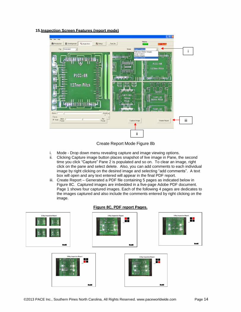
15. Inspection Screen Features (report mode)
i
iii
ii
Create Report Mode Figure 8b
i. Mode - Drop down menu revealing capture and image viewing options. ii. Clicking Capture image button places snapshot of live image in Pane, the second
time you click “Capture” Pane 2 is populated and so on. To clear an image, right click on the pane and select delete. Also, you can add comments to each individual image by right clicking on the desired image and selecting “add comments”. A text box will open and any text entered will appear in the final PDF report.
iii. Create Report – Generated a PDF file containing 5 pages as indicated below in Figure 8C. Captured images are imbedded in a five-page Adobe PDF document. Page 1 shows four captured images. Each of the following 4 pages are dedicates to the images captured and also include the comments entered by right clicking on the image.
Figure 8C, PDF report Pages.
©2013 PACE Inc., Southern Pines North Carolina, All Rights Reserved. www.paceworldwide.com Page 15
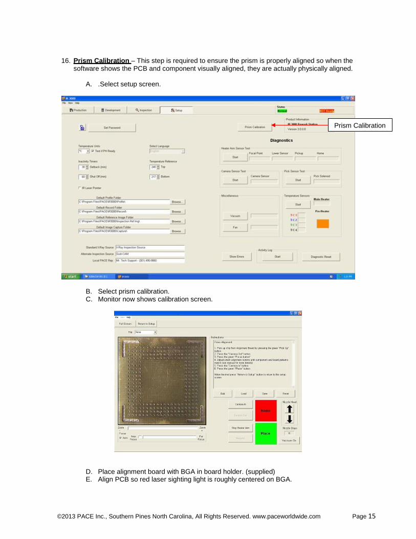
16. Prism Calibration – This step is required to ensure the prism is properly aligned so when the software shows the PCB and component visually aligned, they are actually physically aligned.
A. .Select setup screen.
Prism Calibration
B. Select prism calibration. C. Monitor now shows calibration screen.
D. Place alignment board with BGA in board holder. (supplied) E. Align PCB so red laser sighting light is roughly centered on BGA.
©2013 PACE Inc., Southern Pines North Carolina, All Rights Reserved. www.paceworldwide.com Page 16
F. Mouse click on green button, “Pickup.” G. Mouse click “OK” when message prompt (Please
load PCB into board holder) appears. H. The heater head will go down to the PCB and pick
up the component. It will then return to the home position.
I. Click camera out button J. Click on green “Focus” button and the heater head will
go to the “focus” position. K. You may have to move the part up or down as
discussed previously to make sure the leads and pads are the same physical size in the viewing pane.
L. Align image of board with image of component and click the “place” button.
M. Adjust focus and zoom with up and down arrows on keyboard or by moving the appropriate slide bars.
N. The solder balls on the part and the holes in the alignment board should line up, if they do not, adjust prism until it does.
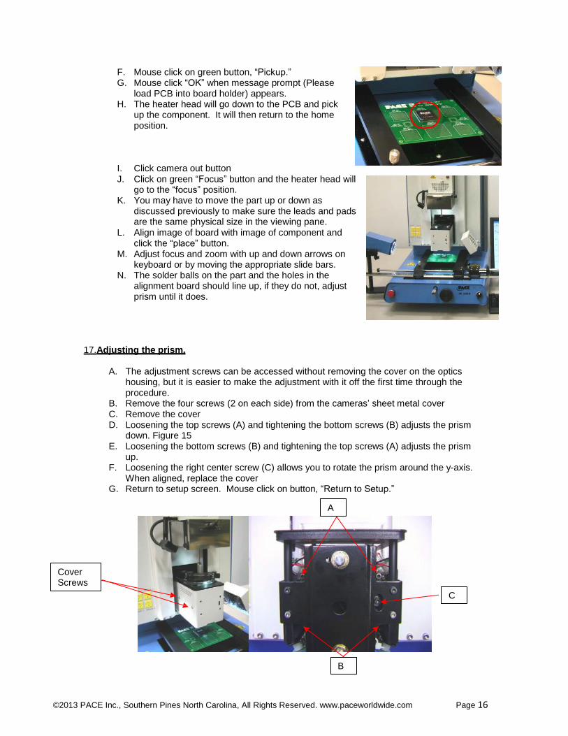
17. Adjusting the prism.
A. The adjustment screws can be accessed without removing the cover on the optics housing, but it is easier to make the adjustment with it off the first time through the procedure.
B. Remove the four screws (2 on each side) from the cameras’ sheet metal cover C. Remove the cover D. Loosening the top screws (A) and tightening the bottom screws (B) adjusts the prism
down. Figure 15 E. Loosening the bottom screws (B) and tightening the top screws (A) adjusts the prism
up. F. Loosening the right center screw (C) allows you to rotate the prism around the y-axis.
When aligned, replace the cover G. Return to setup screen. Mouse click on button, “Return to Setup.”
A
Cover Screws
C
B
©2013 PACE Inc., Southern Pines North Carolina, All Rights Reserved. www.paceworldwide.com Page 17
18. Operation
Note: It is recommended that the IR 3000 be turned on for at least 10 minutes before use to ensure the bottom side heater has reached its set temperature and stabilized and the red ceramic cover is also saturated with heat. Once the bottom side heater is at operating temperature it will deliver consistent heating, ensuring highly repeatable heating from operation to operation. It is also advisable to conduct a trial operation each day to ensure all systems are operating properly. It is important to verify the airflow of the unit with each profile to be run. Verify that the devices/parts being soldered to the PCB do not exceed the height limitations. Exceeding the limitations may interfere with the operation of the machine. The maximum height of any component or device on the top of the PCB is limited to 30mm (1.2”). The maximum height of any component or device on the bottom of the PCB is limited to 15 mm (0.6”).
Note: If at any time you need to abort the process mouse click on the Red “ABORT” button
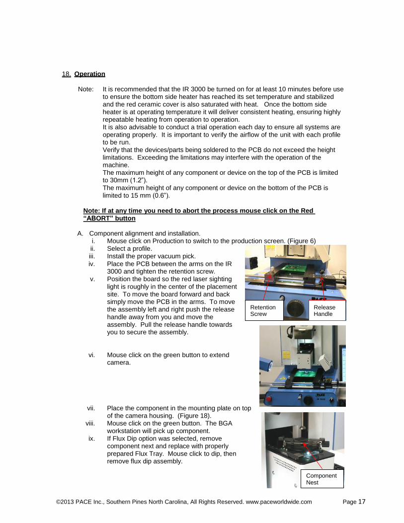
A. Component alignment and installation.
i. Mouse click on Production to switch to the production screen. (Figure 6) ii. Select a profile. iii. Install the proper vacuum pick. iv. Place the PCB between the arms on the IR
3000 and tighten the retention screw. v. Position the board so the red laser sighting
light is roughly in the center of the placement site. To move the board forward and back simply move the PCB in the arms. To move the assembly left and right push the release handle away from you and move the assembly. Pull the release handle towards you to secure the assembly.
vi. Mouse click on the green button to extend camera.
Retention Screw
Release Handle
vii. Place the component in the mounting plate on top
of the camera housing. (Figure 18). viii. Mouse click on the green button. The BGA
workstation will pick up component. ix. If Flux Dip option was selected, remove
component next and replace with properly prepared Flux Tray. Mouse click to dip, then remove flux dip assembly.
Component Nest
©2013 PACE Inc., Southern Pines North Carolina, All Rights Reserved. www.paceworldwide.com Page 18
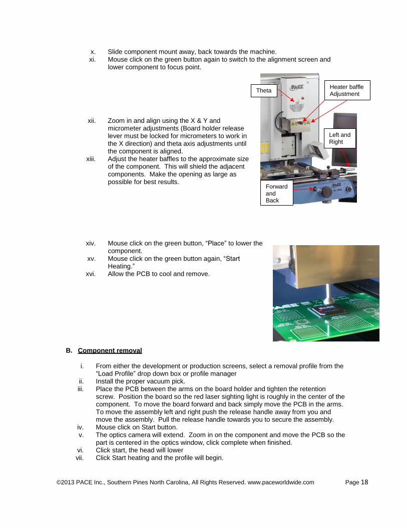
x. Slide component mount away, back towards the machine. xi. Mouse click on the green button again to switch to the alignment screen and
lower component to focus point.
Theta Heater baffle Adjustment
xii. Zoom in and align using the X & Y and micrometer adjustments (Board holder release lever must be locked for micrometers to work in the X direction) and theta axis adjustments until the component is aligned.
xiii. Adjust the heater baffles to the approximate size of the component. This will shield the adjacent components. Make the opening as large as possible for best results.
xiv. Mouse click on the green button, “Place” to lower the component.
xv. Mouse click on the green button again, “Start Heating.”
xvi. Allow the PCB to cool and remove.
B. Component removal
Forward and Back
Left and Right
i. From either the development or production screens, select a removal profile from the “Load Profile” drop down box or profile manager
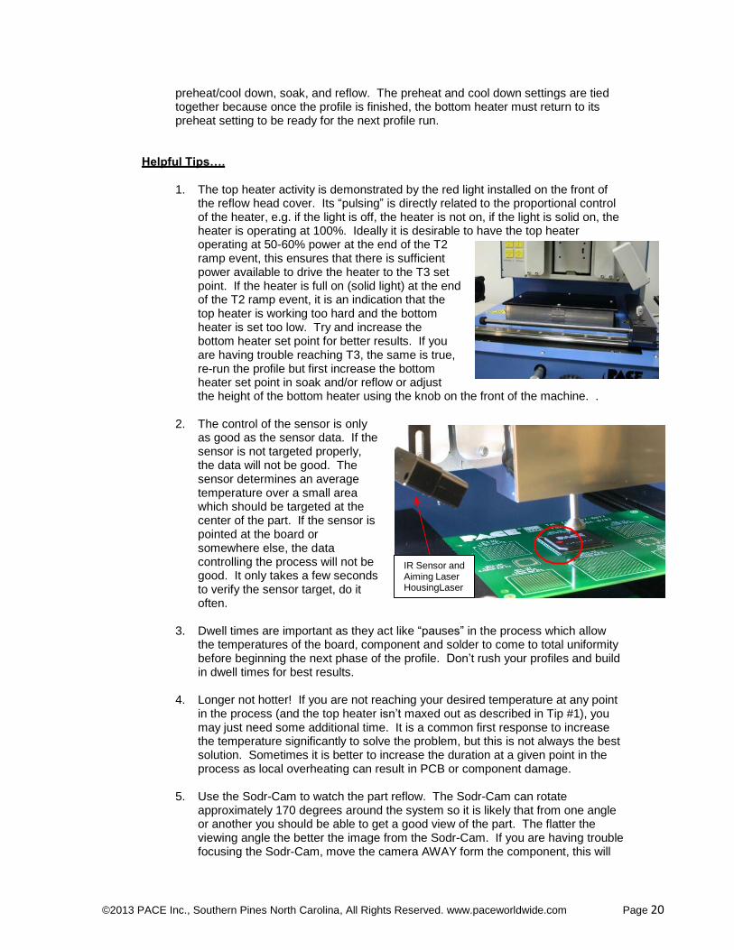
ii. Install the proper vacuum pick. iii. Place the PCB between the arms on the board holder and tighten the retention
screw. Position the board so the red laser sighting light is roughly in the center of the component. To move the board forward and back simply move the PCB in the arms. To move the assembly left and right push the release handle away from you and move the assembly. Pull the release handle towards you to secure the assembly.
iv. Mouse click on Start button. v. The optics camera will extend. Zoom in on the component and move the PCB so the
part is centered in the optics window, click complete when finished. vi. Click start, the head will lower vii. Click Start heating and the profile will begin.

©2013 PACE Inc., Southern Pines North Carolina, All Rights Reserved. www.paceworldwide.com Page 19
viii. If manual removal was selected, you will need to use the hand held vacuum pick to remove the part, if Auto was selected, the heater’s vacuum pik will lower and will lift the part when the heating cycle is over.
ix. Allow PCB and component to cool before removing.
C. Profile development installation procedure.
Note: General Information concerning the Profile Development Screen
The Reflow Graph area displays a representation of the Reflow cycle profile. Time in minutes is graphed along the X-axis and temperature is plotted along the Y- axis. The time and temperature axes incorporate a dynamic scaling feature to optimize the display. Profile graphs can be saved with profiles to be used for process validation by operators while using the Production screen. Profile graphs can also be stored as individual records for each rework job for quality control purposes. Colored lines are used to indicate profile parameters on the graph.
Profile Creation
The IR 3000 is VERY easy to use and there are two methods of creating a profile. The first and easiest is to use the IR sensor. When the reflow head is down over the part to be installed, align the IR sensor using the laser pointer that can be turned on and off in the set-up screen. The laser should point just to the left of center of the part for best results. The IR sensor is used to control the process in real time and is a non contact method of measuring temperature so you don’t have to use a sacrificial board to develop the profile as on most typical hot air systems. However, if you want to use a thermocouple mounted under the part to control the process (Option 2), you can switch the control sensor from the IR sensor to the T/C sensor (MUST BE PLUGGED INTO THE “SENSOR 1” INPUT) in the profile manager. The same procedure as described below applies for both options.
The parameters that can be set in the profile manager are target temps, duration (time), Dwell times, and bottom heater set points. T1, T2, & T3 are set points that guide the system when installing a part. T1 is typically the desired temperature at the end of the preheat phase. T2 is typically the temperature you want on the part at the end of soak, usually defined by the flux activation temp and other factors. T3 is the maximum temperature you want to see on the part at reflow. All T points are settable in the profile manager or by clicking on them in the graph and dragging them around. The T set points combined with time define a ramp rate (Temp/Time) or slope of the line. In general slopes of 0.5 to 0.7 are desirable as they are gentle, even and allow for temperature uniformity. The graph will show the slope/ramp rate as you move the T set points. Time can be set by dragging the T points horizontally on the graph or by entering them manually.
Tc is the melting temperature of the solder you are using. This can be used to calibrate the system.
Dwell times are the amount of time you want the process to remain at the T set points. For example if you define a T3 dwell time of 30 seconds, the system will maintain the temperature of the part at T3 for 30 seconds once it has been reached.
The bottom heater is very important when heating a part. Ideally you want equal heat flowing from the bottom and top to reduce the temperature delta between the part and the PCB. The bottom heater can be set from 1 to 10. Usually a set point of 5 or 6 is sufficient. The set points for the bottom heater can be set individually for
©2013 PACE Inc., Southern Pines North Carolina, All Rights Reserved. www.paceworldwide.com Page 20
preheat/cool down, soak, and reflow. The preheat and cool down settings are tied together because once the profile is finished, the bottom heater must return to its preheat setting to be ready for the next profile run.
Helpful Tips….
1. The top heater activity is demonstrated by the red light installed on the front of the reflow head cover. Its “pulsing” is directly related to the proportional control of the heater, e.g. if the light is off, the heater is not on, if the light is solid on, the heater is operating at 100%. Ideally it is desirable to have the top heater operating at 50-60% power at the end of the T2 ramp event, this ensures that there is sufficient power available to drive the heater to the T3 set point. If the heater is full on (solid light) at the end of the T2 ramp event, it is an indication that the top heater is working too hard and the bottom heater is set too low. Try and increase the bottom heater set point for better results. If you are having trouble reaching T3, the same is true, re-run the profile but first increase the bottom heater set point in soak and/or reflow or adjust the height of the bottom heater using the knob on the front of the machine. .
2. The control of the sensor is only as good as the sensor data. If the sensor is not targeted properly, the data will not be good. The sensor determines an average temperature over a small area which should be targeted at the center of the part. If the sensor is pointed at the board or somewhere else, the data controlling the process will not be good. It only takes a few seconds to verify the sensor target, do it often.
IR Sensor and Aiming Laser HousingLaser
3. Dwell times are important as they act like “pauses” in the process which allow the temperatures of the board, component and solder to come to total uniformity before beginning the next phase of the profile. Don’t rush your profiles and build in dwell times for best results.
4. Longer not hotter! If you are not reaching your desired temperature at any point
in the process (and the top heater isn’t maxed out as described in Tip #1), you may just need some additional time. It is a common first response to increase the temperature significantly to solve the problem, but this is not always the best solution. Sometimes it is better to increase the duration at a given point in the process as local overheating can result in PCB or component damage.
5. Use the Sodr-Cam to watch the part reflow. The Sodr-Cam can rotate
approximately 170 degrees around the system so it is likely that from one angle or another you should be able to get a good view of the part. The flatter the viewing angle the better the image from the Sodr-Cam. If you are having trouble focusing the Sodr-Cam, move the camera AWAY form the component, this will

©2013 PACE Inc., Southern Pines North Carolina, All Rights Reserved. www.paceworldwide.com Page 21
increase the focal length and will improve the image. It is normal to try and move it closer but it will not help.
6. Once the process has entered a ramp event, you will be unable to adjust the
next T setting or the time. The auto control of the ramp between T1/T2 or T2/T3 is achieved by a sophisticated PID software control algorithm. Once the process enters a ramp event, the end points govern the auto control function and can not be changed.
7. The system comes preloaded with a removal and an installation profile. In
general terms, these are a good starting point but your specific needs/specifications/configuration will determine the final results. Modify them as needed and save them as your own.
8. Always use the smallest sized pick that will work for the application.
General Heating Information on Temperatures and Ramp Rates
Acceptable ramp rates and maximum temperatures should be obtained from the component manufacturer. Typical ramp rates are 2-5 ºC/s (4-9 ºF/s) for plastic parts and 1 ºC/s (2 ºF/s) for ceramic parts. It is recommended to select a maximum temperature (T3) below the manufacturer’s specification to provide for a margin of safety. Typically, 20 ºC below maximum specified temperature is selected if possible depending on the various solders used on components. This may not be possible with some of the lead free alloys used.
Pre-Heat Phase
1. In a “step profile”, the PCB and package should reach a stable temperature (T1) of 100-110ºC. If plotting the temperature curve, the trace will usually level off within this temperature range. 2. If a “linear slope” profile is desired, pre-heat and soak phases are combined. Both the package and the PCB are warmed at a constant ramp rate until the desired soak temperature is reached (T2).
Soak Phase
The soak phase is a crucial part of the process. During this period, the flux activates and drives off volatiles and excess flux. A temperature of 145-175 ºC (determined by the activation temperature of the flux used) should be maintained for approximately 20-40 seconds. This allows for uniform ramping across the entire package and PCB during reflow.
Reflow Phase
During this phase, the solder reaches solder melt and forms joints between the package and the lands. It is critical for all areas of the component to reach solder melt together and all solder joints remain in a liquid state for at least 10-20 seconds. Generally, plastic packages should not be exposed to temperatures higher than 240 ºC. Always consult the device specifications for maximum temperature recommendations. As a rule of thumb, a safe “maximum temperature” is the maximum temp specified by the manufacturer minus 20 ºC. The lowest heater set temperatures possible should always be used to ensure safety of the device and PCB.
Cool Down Phase
The cool down phase is necessary to bring the temperature of the package, solder joints and PCB under the package below solder melt temperatures. Cooling should
©2013 PACE Inc., Southern Pines North Carolina, All Rights Reserved. www.paceworldwide.com Page 22
be controlled. A good reference is to use the same cool down rate as for ramp up. The cooling fan on the IR 3000 will run for 90 seconds from the start of the cool down cycle. Some types of components (like CBGAs) should be allowed to cool without external assistance from the cooling fan. When installing these packages, turn the fan away from the PCB so the air doesn’t blow on it.
19. Maintenance
Caution: Disconnect the main power supply and computer cables before opening the BGA workstation door, replacing any component or before performing any routine maintenance.
a. Periodically inspect the power cords and other cables for signs of wear or
damage. If wear or damage is found, replace the cord or cable immediately. b. The work surface and housing should be cleaned periodically with a soft damp
cloth. c. The camera glass window should be cleaned periodically with glass cleaner and
a soft cloth.
Maintenance beyond this should only be completed by a qualified PACE service technician.
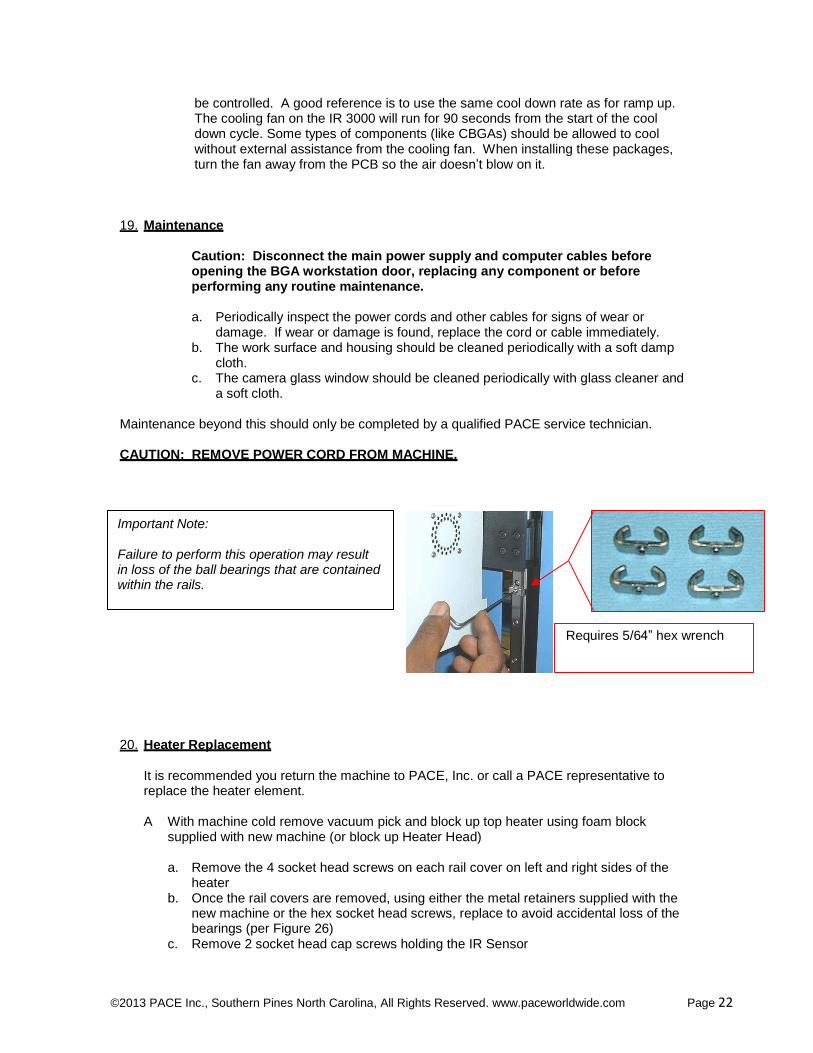
CAUTION: REMOVE POWER CORD FROM MACHINE.
Important Note: Failure to perform this operation may result in loss of the ball bearings that are contained within the rails.
Requires 5/64” hex wrench
20. Heater Replacement
It is recommended you return the machine to PACE, Inc. or call a PACE representative to replace the heater element.
A With machine cold remove vacuum pick and block up top heater using foam block
supplied with new machine (or block up Heater Head)
a. Remove the 4 socket head screws on each rail cover on left and right sides of the
heater b. Once the rail covers are removed, using either the metal retainers supplied with the
new machine or the hex socket head screws, replace to avoid accidental loss of the bearings (per Figure 26)
c. Remove 2 socket head cap screws holding the IR Sensor
©2013 PACE Inc., Southern Pines North Carolina, All Rights Reserved. www.paceworldwide.com Page 23
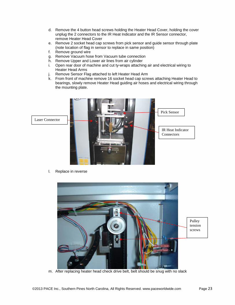
d. Remove the 4 button head screws holding the Heater Head Cover, holding the cover unplug the 2 connectors to the IR Heat Indicator and the IR Sensor connector, remove Heater Head Cover
e. Remove 2 socket head cap screws from pick sensor and guide sensor through plate (note location of flag in sensor to replace in same position)
f. Remove ground wire g. Remove Vacuum hose from Vacuum tube connection h. Remove Upper and Lower air lines from air cylinder i. Open rear door of machine and cut ty-wraps attaching air and electrical wiring to
Heater Head Arms j. Remove Sensor Flag attached to left Heater Head Arm k. From front of machine remove 16 socket head cap screws attaching Heater Head to
bearings, slowly remove Heater Head guiding air hoses and electrical wiring through the mounting plate.
Laser Connector
Pick Sensor
IR Heat Indicator
Connectors
l. Replace in reverse
Pulley
tension
screws
m. After replacing heater head check drive belt, belt should be snug with no slack
©2013 PACE Inc., Southern Pines North Carolina, All Rights Reserved. www.paceworldwide.com Page 24
n. To adjust loosen 2 pulley tension screws holding weight of heater to not let it fall o. Push up bracket until slack is removed tighten screws p. When finished perform Heater Head Sensor Test to check movement readjust as
needed
21. Adjustments and Alignments
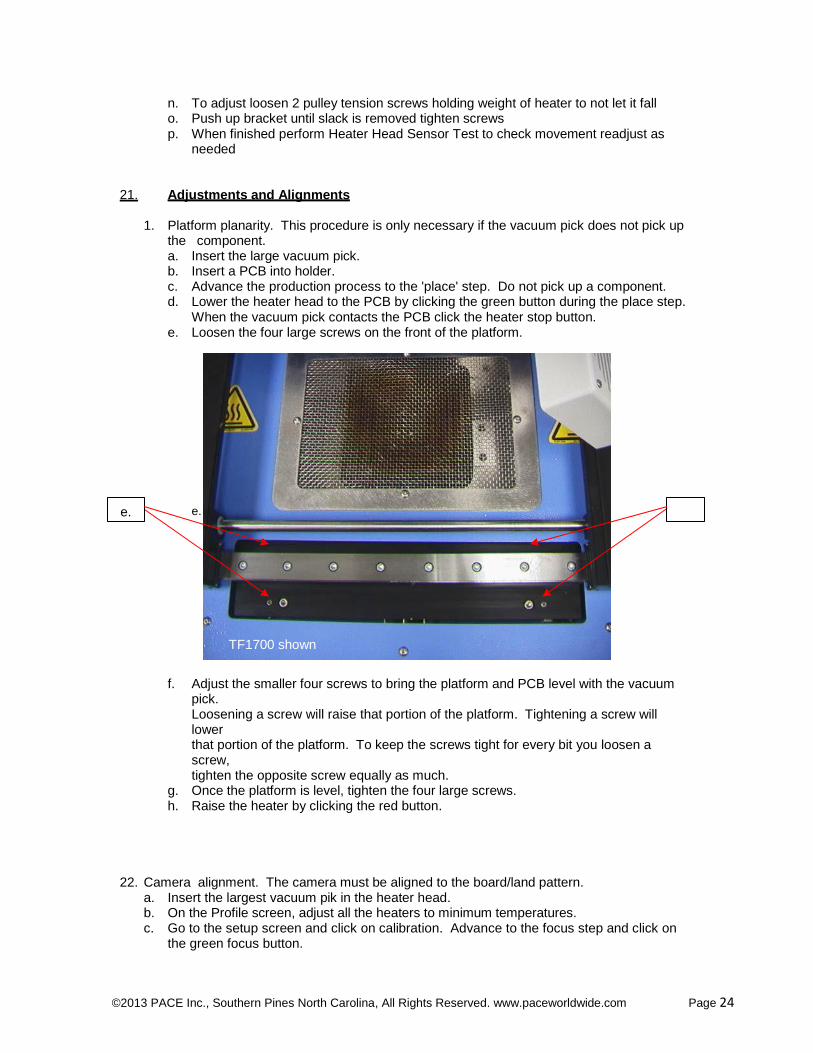
1. Platform planarity. This procedure is only necessary if the vacuum pick does not pick up the component. a. Insert the large vacuum pick. b. Insert a PCB into holder. c. Advance the production process to the 'place' step. Do not pick up a component. d. Lower the heater head to the PCB by clicking the green button during the place step.
When the vacuum pick contacts the PCB click the heater stop button. e. Loosen the four large screws on the front of the platform.
e. e.
TF1700 shown
f. Adjust the smaller four screws to bring the platform and PCB level with the vacuum
pick. Loosening a screw will raise that portion of the platform. Tightening a screw will lower that portion of the platform. To keep the screws tight for every bit you loosen a screw, tighten the opposite screw equally as much.
g. Once the platform is level, tighten the four large screws. h. Raise the heater by clicking the red button.
22. Camera alignment. The camera must be aligned to the board/land pattern. a. Insert the largest vacuum pik in the heater head. b. On the Profile screen, adjust all the heaters to minimum temperatures. c. Go to the setup screen and click on calibration. Advance to the focus step and click on
the green focus button.
©2013 PACE Inc., Southern Pines North Carolina, All Rights Reserved. www.paceworldwide.com Page 25
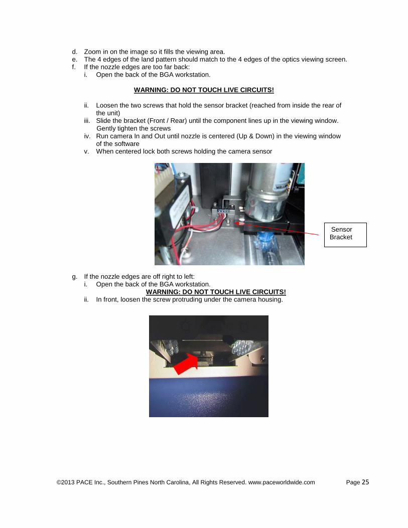
d. Zoom in on the image so it fills the viewing area. e. The 4 edges of the land pattern should match to the 4 edges of the optics viewing screen. f. If the nozzle edges are too far back:
i. Open the back of the BGA workstation.
WARNING: DO NOT TOUCH LIVE CIRCUITS!
ii. Loosen the two screws that hold the sensor bracket (reached from inside the rear of
the unit) iii. Slide the bracket (Front / Rear) until the component lines up in the viewing window.
Gently tighten the screws iv. Run camera In and Out until nozzle is centered (Up & Down) in the viewing window
of the software v. When centered lock both screws holding the camera sensor
Sensor Bracket
g. If the nozzle edges are off right to left:
i. Open the back of the BGA workstation. WARNING: DO NOT TOUCH LIVE CIRCUITS!
ii. In front, loosen the screw protruding under the camera housing.
©2013 PACE Inc., Southern Pines North Carolina, All Rights Reserved. www.paceworldwide.com Page 26
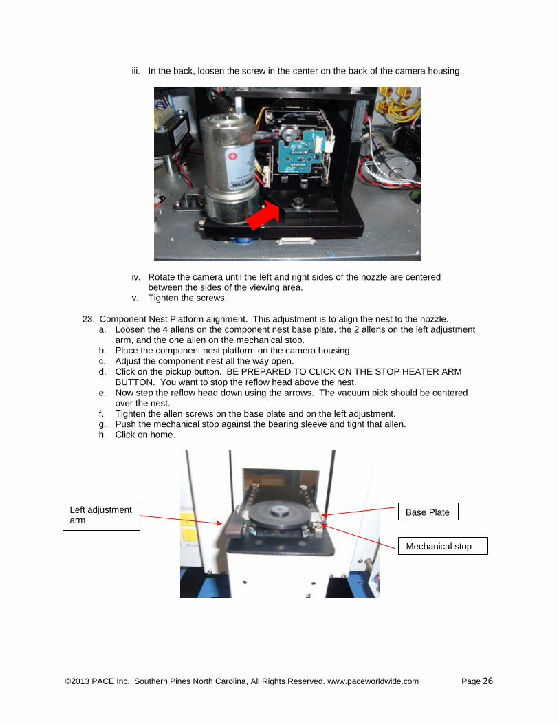
iii. In the back, loosen the screw in the center on the back of the camera housing.
iv. Rotate the camera until the left and right sides of the nozzle are centered between the sides of the viewing area.
v. Tighten the screws.
23. Component Nest Platform alignment. This adjustment is to align the nest to the nozzle. a. Loosen the 4 allens on the component nest base plate, the 2 allens on the left adjustment
arm, and the one allen on the mechanical stop. b. Place the component nest platform on the camera housing. c. Adjust the component nest all the way open. d. Click on the pickup button. BE PREPARED TO CLICK ON THE STOP HEATER ARM
BUTTON. You want to stop the reflow head above the nest. e. Now step the reflow head down using the arrows. The vacuum pick should be centered
over the nest. f. Tighten the allen screws on the base plate and on the left adjustment. g. Push the mechanical stop against the bearing sleeve and tight that allen. h. Click on home.
Left adjustment arm
Base Plate
Mechanical stop
©2013 PACE Inc., Southern Pines North Carolina, All Rights Reserved. www.paceworldwide.com Page 27
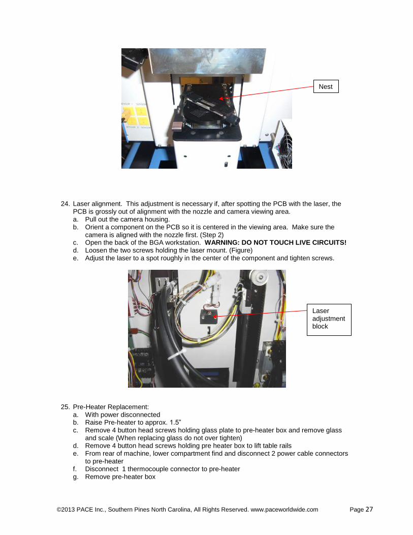
Nest
24. Laser alignment. This adjustment is necessary if, after spotting the PCB with the laser, the PCB is grossly out of alignment with the nozzle and camera viewing area. a. Pull out the camera housing. b. Orient a component on the PCB so it is centered in the viewing area. Make sure the
camera is aligned with the nozzle first. (Step 2) c. Open the back of the BGA workstation. WARNING: DO NOT TOUCH LIVE CIRCUITS! d. Loosen the two screws holding the laser mount. (Figure) e. Adjust the laser to a spot roughly in the center of the component and tighten screws.
Laser adjustment block
25. Pre-Heater Replacement:
a. With power disconnected b. Raise Pre-heater to approx. 1.5” c. Remove 4 button head screws holding glass plate to pre-heater box and remove glass
and scale (When replacing glass do not over tighten) d. Remove 4 button head screws holding pre heater box to lift table rails e. From rear of machine, lower compartment find and disconnect 2 power cable connectors
to pre-heater f. Disconnect 1 thermocouple connector to pre-heater g. Remove pre-heater box
©2013 PACE Inc., Southern Pines North Carolina, All Rights Reserved. www.paceworldwide.com Page 28
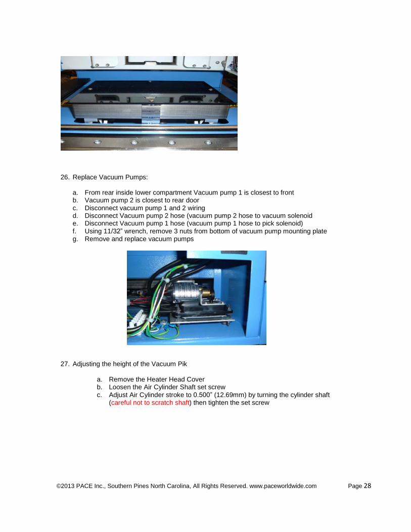
26. Replace Vacuum Pumps:
a. From rear inside lower compartment Vacuum pump 1 is closest to front b. Vacuum pump 2 is closest to rear door c. Disconnect vacuum pump 1 and 2 wiring d. Disconnect Vacuum pump 2 hose (vacuum pump 2 hose to vacuum solenoid e. Disconnect Vacuum pump 1 hose (vacuum pump 1 hose to pick solenoid) f. Using 11/32” wrench, remove 3 nuts from bottom of vacuum pump mounting plate g. Remove and replace vacuum pumps
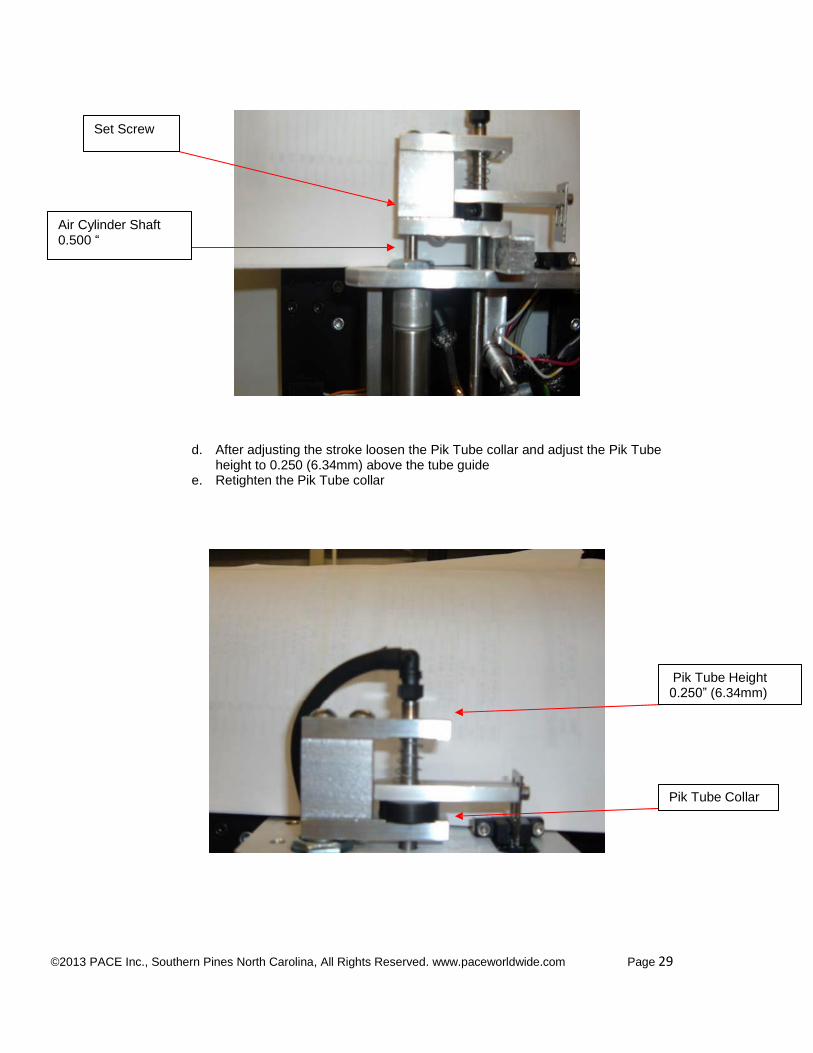
27. Adjusting the height of the Vacuum Pik
a. Remove the Heater Head Cover b. Loosen the Air Cylinder Shaft set screw c. Adjust Air Cylinder stroke to 0.500” (12.69mm) by turning the cylinder shaft
(careful not to scratch shaft) then tighten the set screw
©2013 PACE Inc., Southern Pines North Carolina, All Rights Reserved. www.paceworldwide.com Page 29
Set Screw
Air Cylinder Shaft 0.500 “
d. After adjusting the stroke loosen the Pik Tube collar and adjust the Pik Tube height to 0.250 (6.34mm) above the tube guide
e. Retighten the Pik Tube collar
Pik Tube Height 0.250” (6.34mm)
Pik Tube Collar
©2013 PACE Inc., Southern Pines North Carolina, All Rights Reserved. www.paceworldwide.com Page 30
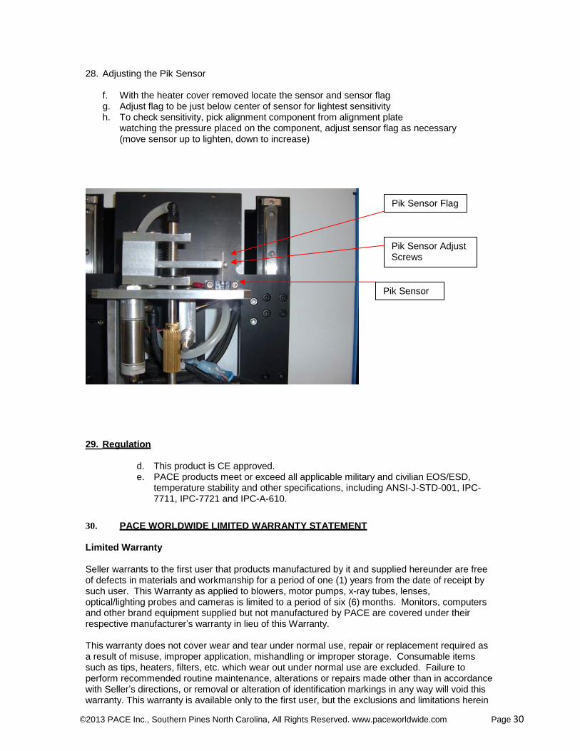
28. Adjusting the Pik Sensor
f. With the heater cover removed locate the sensor and sensor flag g. Adjust flag to be just below center of sensor for lightest sensitivity h. To check sensitivity, pick alignment component from alignment plate
watching the pressure placed on the component, adjust sensor flag as necessary (move sensor up to lighten, down to increase)
Pik Sensor Flag
Pik Sensor Adjust Screws
Pik Sensor
29. Regulation
d. This product is CE approved. e. PACE products meet or exceed all applicable military and civilian EOS/ESD,
temperature stability and other specifications, including ANSI-J-STD-001, IPC- 7711, IPC-7721 and IPC-A-610.
30. PACE WORLDWIDE LIMITED WARRANTY STATEMENT
Limited Warranty
Seller warrants to the first user that products manufactured by it and supplied hereunder are free of defects in materials and workmanship for a period of one (1) years from the date of receipt by such user. This Warranty as applied to blowers, motor pumps, x-ray tubes, lenses, optical/lighting probes and cameras is limited to a period of six (6) months. Monitors, computers and other brand equipment supplied but not manufactured by PACE are covered under their respective manufacturer’s warranty in lieu of this Warranty.
This warranty does not cover wear and tear under normal use, repair or replacement required as a result of misuse, improper application, mishandling or improper storage. Consumable items such as tips, heaters, filters, etc. which wear out under normal use are excluded. Failure to perform recommended routine maintenance, alterations or repairs made other than in accordance with Seller’s directions, or removal or alteration of identification markings in any way will void this warranty. This warranty is available only to the first user, but the exclusions and limitations herein

©2013 PACE Inc., Southern Pines North Carolina, All Rights Reserved. www.paceworldwide.com Page 31
apply to all persons and entities.
SELLER MAKES NO OTHER WARRANTY, EXPRESS OR IMPLIED, AND MAKES NO WARRANTY OF MERCHANTABILITY OR FITNESS FOR A PARTICULAR PURPOSE.
Seller will, at its option, repair or replace any defective products at its facility or other location approved by it at no charge to user, or provide parts without charge for installation by the user in the field at user’s expense and risk. User will be responsible for all costs of shipping equipment to Seller or other location for warranty service.
EXCEPT FOR THE REMEDY ABOVE DESCRIBED, UNLESS OTHERWISE REQUIRED BY APPLICABLE LAW, SELLER WILL HAVE NO OTHER OBLIGATION WITH REGARD TO ANY BREACH OF WARRANTY OR OTHER CLAIM WITH RESPECT TO THE PRODUCTS, OR LIABILITY FOR ANY DIRECT, INDIRECT, CONSEQUENTIAL, OR INCIDENTAL LOSS OR DAMAGE CAUSED BY OR OCCURRING IN CONNECTION WITH ANY OF THE PRODUCTS.
Warranty service may be obtained by contacting the appropriate PACE Company or local Authorized PACE distributor as set forth below to determine if return of any item is required, or if repairs can be made by the user in the field. Any warranty or other claim with respect to the products must be made with sufficient evidence of purchase and date of receipt, otherwise user’s rights under this warranty shall be deemed waived. PACE Incorporated retains the right to make changes to specifications contained herein at any time, without notice. Contact your local authorized PACE Distributor or PACE Incorporated to obtain the latest specifications.
The following are trademarks and/or service marks of PACE, Incorporated, NC, USA.
INSTACAL®, FUMEFLO
®, HEATWISE
®, PACEWORLDWIDE
®, PERMAGROUND
®,
POWERMODULE®, and TEMPWISE
®
The following are registered trademarks and/or service marks of PACE Incorporated, Southern Pines, North Carolina U.S.A.
ARM-EVAC
®, FLO-D-SODR
®, MINIWAVE®, PACE
®, SENSATEMP
®, SNAPVAC
®,
SODRTEK®, SODR-X-TRACTOR
®, THERMOFLO
®, THERMOJET
®, THERMOTWEEZ
®, and
VISIFILTER®
PACE products meet or exceed all applicable military and civilian EOS/ESD, temperature stability and other specifications including MIL STD 2000, ANSI/JSTD 001, IPC7711, and IPC A-610.
PACE Incorporated Pace Europe 255 Air Tool Drive 11 Holdom Avenue Southern Pines, Bletchley, Milton Keynes, North Carolina, 28387 United Kingdom, MK11QU Tel: (877) 882-PACE Tel: 011 44 1908 277666 Tel: (910) 695-7223 Fax: 011 44 1908 277777
Fax: (910) 695-1594