Embed Size (px)
Citation preview
GeneralSpecifications
IR400Infrared Gas Analyzer
GS 11G02N01-01E
GS 11G02N01-01E©Copyright Jun. 20027th Edition May 2019
The IR400 infrared gas analyzer is capable of measuring the concentrations of NO, SO2, CO2, CO, CH4 and O2 components in sample gas.NO, SO2, CO2, CO and CH4 are measured by non-dispersive infrared method (NDIR), while O2 is measured by built-in paramagnetic sensor or external zirconia analyzer. A maximum of 5 components including O2 (up to 4 components except for O2 measurement) are simultaneously measurable.The mass flow type twin detector of high sensitivity and reliability adopted in the infrared ray method detection unit makes the measurement hardly affected by interfering components.In addition, the IR400 includes a microprocessor and has a large-size liquid crystal display, providing easy operation, high accuracy and multiple functions.Optimum as an analyzer unit of measurement system for combustion exhaust gas from refuse incinerator and boiler, or gas from different industrial furnaces.
Features1. Simultaneous and continuous measurement of up to
5 components including O2 O2 and 4 components selected from among NO,
SO2, CO, CO2, and CH4.2. Minimal interference from other gas components Themassflowtypetwindetectorofhighsensitivity
and reliability minimizes interference from other gas components, ensuring excellent stability.3.Extensivefunctions Incorporating O2correction,averagevalue
computing, automatic calibration, one touch calibration,upper/lowerlimitalarm,remotemeasurementrangechangeover,rangeidentificationsignal output, etc., the analyzer accommodates differentapplicationrequirements.
4. Easy-to-read, large LCD LargeLCDprovidesclearindicationsofallmeasuredcomponentsandcomputedvaluesandeasyinteractiveoperation.
5. 19-inch rack mounting Unitized construction of the main body on the 19-
inch rack and of the signal input/output terminal moduleallowseasyconfigurationofagasanalyzersystem.
6. Maximum measuring range ratio Amaximumrangeratioof1:25isachieved.7. Zero drift ±1%offullscale/week(forrangemorethan200ppm)
SpecificationsStandardSpecifications
Measurement principle:NO, SO2, CO2, CO, CH4: Non-dispersiveinfrared
method Single light source-double beams
O2: Paramagnetictype(built-in),orzirconiatype(external)
Measurable gas components and measuring ranges:
RangeComponent Minimumrange Maximumrange
NO 0 – 50 ppm 0 – 5000 ppmSO2 0 – 50 ppm 0–10vol%CO2 0 – 20 ppm 0–100vol%CO 0 – 50 ppm 0–100vol%CH4 0 – 200 ppm 0–100vol%
O2(paramagnetic) 0–5vol% 0–25vol%O2(zirconia) 0–5vol% 0–25vol%
• Measurement of up to 5 components including O2.• 1 or 2 measuring range per component.•Measuringrangeratio ≤1:5(O2 analyzer)
≤1:25(exceptO2 analyzer)For measurable components and possible combinations of measuring ranges, refer to Measurable Components and Ranges page10 through 11.Display:Digitalindicationin4digits(LCDwithbacklight)•Instantaneousvalueofeachcomponent•InstantaneousvalueafterO2 correction(onlyinNO,SO2,COwithO2 measurement)•AveragevalueafterO2 correction(onlyinNO,SO2,COwithO2 measurement)•AverageO2value
Analog output signal: 4 to 20 mA DC or 0 to 1 V DC, non-isolated, 12 points max. Analog output corresponds one-to-one withmeasuredvalueindication.
* Input/Outputofanalogsignalsisavailableincombinationwiththeinput/outputterminalmodule.
Permissible load resistance: 550Ωmax.for4to20mADC 100kΩmin.for0to1VDC
*: Refer to the table “Measurable Components and the Corresponding Channel Numbers” of Page 17,forthechannelnumbersofdisplayedvaluesand analog output signals.
YokogawaElectricCorporation2-9-32, Nakacho, Musashino-shi, Tokyo, 180-8750 JapanTel.: 81-422-52-5617 Fax.: 81-422-52-6792
[Style : S4]
2
All Rights Reserved. Copyright © 2002, Yokogawa Electric Corporation GS 11G02N01-01E
Analog Input Signal : For signal input from external O2 analyzer,
Signalrequirement; (1)SignalfromYokogawa’szirconiaO2
analyzer(ModelZX8D*CorZX8D*D) (2)0to1VDCfromanO2sensor
Input section is not isolated. This featureiseffectivewhenbuilt-inO2 sensor is not used.
(Aninputsignaltriggersmeasuredconcentrationindication and O2 correction.)
* : External O2 analyzer should be purchased separately.Relay contact output:
1acontact(250VAC/2A,resistiveload) Instrument error, calibration error, range
identification,autocalibrationstatus,pumpON/OFF, peak alarm.
1ccontact(250VAC/2A,resistiveload) Selectable 6 outputs.
High/Lowlimitalarmcontactoutput(foreach channel).
Powerdisconnectionalarm.* All relay contacts are isolated mutually
and from the internal circuit.Contact input:
Non-voltagecontact(ON/0V,OFF/5VDC,5mAflowingatON).Remote range changeover,autocalibrationremotestart,remotehold,averagevaluereset,pumpON/OFF. Isolated from the internal circuit withphotocoupler.Contactinputsarenotisolated from one another.
Transmission output: Solenoidvalvedrivesignalforautomaticcalibration.Transistoroutput(100mAorless)
* For details, see External Connection Diagram on page 16.
Powersupply:Voltagerating; 100to240VACAllowablerange; 85to264VACFrequency; 50/60HzPowerconsumption; 250VAmax.Inlet; ConformtoEN60320 Protection Class 1
Operating conditions:Ambienttemperature; -5to45°CAmbienthumidity; 90%RH max., non-condensing.
Storage conditions: Ambienttemperature;-20to60°C Ambienthumidity;90%RHmax,non-condensing
Dimensions(H×W×D): Analyzermainunit; 177×483×599mm Input/Outputterminalmodule; 164 × 316 × 55 mm
Weight: Approx.22kg(onlyanalyzer)Finish color:Frontpanel;Off-white(Munsell10Y7.5/0.5orequivalent)Casing; Plating,Steel-blue(gray)
Enclosure: Steel casing, for indoor useMaterial of gas-contacting parts:Gasinlet/outlet; SUS304Samplecell; SUS304/neoprenerubberInfrared-raytransmittingwindow;CaF2O2 analyzersamplingcell;SUS316Internalpiping;Toarontube,Teflontube
Gas inlet/outlet: Rc1/4 or 1/4 NPT internal threadPurgegasflowrate: 1L/min(whenrequired)
Safety, EMC and RoHS conformity standards: WhenusingIR400inEurope,select“Indication,
Powercable”:Cinthesuffixcode.Installationaltitude; 2000morlessPollutiondegree; 2(Note)Installationcategory; II(Note)
Note: Installationcategory,calledovervoltagecategory,specifiesimpulsewithstandingvoltage.CategoryIIisforelectricalequipment.
Pollution degree indicates the degree of existenceofsolid,liquid,gasorotherinclusionswhichreducedielectricstrength.Degree2isthenormalindoorenvironment.
Safety; EN61010-1EMC; EN61326-1ClassA,Table2,
EN61326-2-3, EN61000-3-2, EN61000-3-3, EN61000-6-2 EMC Regulatory Arrangement in
AustraliaandNewZealand(RCM) KoreaElectromagneticConformity(KC) Note: The product mounted in a steel enclosure
conformstotherequirementsofEMCdirective.Caution: TheinstrumentisaClassAproduct,
anditisdesignedforuseintheindustrialenvironment.Pleaseusethisinstrumentintheindustrialenvironmentonly.
RoHS; EN50581InformationoftheWEEEDirective
This product is purposely designed to be used in a largescalefixedinstallationsonlyand,therefore,isoutofscopeoftheWEEEDirective.TheWEEEDirectivedoesnotapply. TheWEEEDirectiveisonlyvalidintheEU.
OptionsDedicatedrelayboard(Optioncode:/R)ThisrelayboardreceivessignalsfromconnectorCN3oftheIR400I/Oterminalmoduleandactivatesthecalibrationsolenoidvalvedirectly.
Relay Contact 1acontact(250VAC/2A,resistiveload)Contact ActionDuringmeasurement; CN1:ON
Others: OFFDuring calibration: CN1: OFF
Others: Contact corresponding to calibration timing is ON
Recommendedconnector(CN1toCN9)Housing; VHR-2N(JST,JapanSolderlessTerminals,)Contact; SVH-21T-1-1(JST)
StandardFunctionsOutput signal hold:
Output signals are kept on hold during the manualorautocalibrationsbyactivationofholding(turning“ON”itssetting). Thevaluestobeonholdaretheonesobtained just before calibration mode starts. Indicationvalueswillnotbeonhold.
7th Edition May 17, 2019-00
3
All Rights Reserved. Copyright © 2002, Yokogawa Electric Corporation GS 11G02N01-01E
Remote output hold: Outputsignalholdsthelatestvalueorsettingvaluebyshort-circuitingtheremote-output-hold input terminals. Holdingismaintainedwhiletheterminalsare short-circuited. But the indicated instantaneousvalueswillnotbeonhold.
Switchrange: Therangechangeoverisavailableinmanual, auto, and remote modes. Only presetchangeovermethodisvalid.
Manual; Allowsrangetoswitchbykeyoperation.Auto; Allowsrangetoswitchfromlowtohigh
rangewhen90%FSormoreisavailableinthelowrange. Allowsrangetoswitchfromhightolowrangewhen80%FSorlessisavailableinthelowrange.
Remote; Non-voltagecontactinput(formeasurablecomponents) Allowsrangetoswitchviaanexternalsignalwhenremoterangechangeoverinputisreceived.
Rangeidentificationsignal: Thepresentmeasuringrangeisidentifiedby a contact signal.
The contact output terminals for each componentareshort-circuitedwhenthefirstrangeisselected,andwhenthesecond range is selected, the terminals are open.
Auto calibration: Auto calibration is carried out periodically at a preset cycle. Whenastandardgascylinderforcalibrationandasolenoidvalveforopening/closingthegasflowlineareprepared externally by the customer, calibrationwillbecarriedoutwiththesolenoidvalvedrivecontactsforzerocalibration and each span calibration turnedon/offsequentiallyatthesetautocalibration timing.
Autocalibrationcyclesetting; Auto calibration cycle is set. Settingisvariablewithin1to99hours(inincrementsof1hour)or1to40days(inincrementsof1day).
Gasflowtimesetting; Thetimeforflowingeachcalibrationgas in auto calibration is set. Settablewithin60to900seconds(inincrements of 1 second)
Auto calibration remote start: Auto calibration is carried out only once according to an external input signal. Calibrationsequenceissettableinthesamewayasthegeneralautocalibration.
Auto calibration starts by opening the auto-calibration-remote-start input terminals after short-circuiting them for 1.5 seconds or longer.
Auto zero calibration: Auto zero calibration is carried out periodically at the preset cycle. This cycle is independent of “Auto calibration” cycle. Whenzerocalibrationgasandsolenoidvalveforopening/closingthecalibrationgasflowlineare prepared externally by the customer, the zerocalibrationwillbecarriedoutatthepresetautozerocalibrationtimingwiththesolenoidvalvedrivecontact(forzerocalibration)turnedon/off.
Autozerocalibrationcyclesetting; Auto zero calibration cycle is set. Settingisvariablewithin1to99hours(inincrementsof1hour)or1to40days(inincrementsof1day)
Gasflowtimesetting; Thetimeforflowingzerogasinautozero calibration is set. Settable60to900seconds(inincrements of 1 second)
Upper/lowerlimitalarm: Alarmcontactoutputturnsonwhenmeasurementvaluereachesthepresetupperorlowerlimitofalarmvalue. Contactsclosewhentheinstantaneousvalueofeachcomponentbecomeslargerthantheupperalarmlimitvalueorsmallerthantheloweralarmlimitvalue.
Instrument error contact output: Contacts close at an occurrence of analyzer error No. 1, 3 or 10.
Calibration error contact output: Contacts close at occurrence of manual or autocalibrationerror(anyoferrorsNo.4to 9).
Auto calibration status contact output: Contacts close during auto calibration.
Pump ON/OFF contact output: During measurement, contacts close. Whilecalibrationgasisflowing,contactsopen.Contactsareconnectedinpowersupply of pump, and stop the sample gas whilecalibrationgasisflowing.
OptionalFunctions(availablewithspecifyingoptionalcode)
O2correction:(-/K) ConversionofmeasuredNO,SO2 and COgasconcentrationsintovaluesatreference O2 concentration.
Correction formula: C =
21 – On
21 – Os× Cs
Where: C: Sample gas concentration after O2
correction Cs: Measured concentration of sample gas Os: Measured O2 concentration (limit
setting: 1 to 20%O2, default 17% ) On: Reference O2 concentration
(valuechangeablebysetting:0to19%O2, default 4%)
The result of calculation is indicated and output in an analog output signal.
7th Edition May 17, 2019-00
4
All Rights Reserved. Copyright © 2002, Yokogawa Electric Corporation GS 11G02N01-01E
AveragevalueafterO2 correction and O2averagevaluecalculation(-/K): The result of O2 correction or instantaneous O2valuecanbeoutputtedasanaveragevalueinthedeterminedperiodoftime. Usedforaveragingisthemovingaveragemethodinwhichsamplingiscarriedoutatintervalsof30seconds. (Outputisupdatedevery30seconds.Itistheaveragevalueinthedeterminedperiodof time just before the latest updating.) Averagingtimeissettablewithin1to59minutes(inincrementsof1minute)or1to4hours(inincrementsof1hour).
Averagevaluereset(-/K): Theabove-mentionedoutputofaveragevaluestartsfromtheinitialstatebyopeningtheaverage-value-resettinginputterminals after short-circuiting them for 1.5 seconds or longer. Output is reset by short-circuiting and restarted by opening.
COconcentrationpeakcountalarm(-/A): (availableonlyforCO+O2 measurement) Alarm output turns on according to the preset concentration and count. WhenevertheinstantaneousvalueofCOexceedsthepresetconcentrationvalue,count increments. If the count exceeds thepresetvalueinonehour,thealarmcontacts close.
Communicationfunction(-/C): RS-232C(9pinsD-sub) Half-duplex bit serial Start-stop synchronization ModbusTM protocol
Contents; Read/writeparameters Read measurement concentration and
instrument statusRemark; WhenconnectingviaRS-485interface,a
RS-232C ←→ RS-485convertershouldbe used.
PerformanceRepeatability: ±0.5%offullscale(±1% of full scale
for range less than 0-50 ppm)Linearity: ±1% of full scaleZerodrift: ±1%offullscale/week
(±2%offullscale/weekforrangeequal to or more than 50 ppm and less than 200ppm) (±2%offullscale/dayforrangeless than 0-50 ppm)
Spandrift: ±2%offullscale/week (±2%offullscale/dayforrangelessthan0-50 ppm)
Responsetime(for90%FSresponse): Within60secondsincludingreplacementtimeofsamplegas(whengasflowrateis0.5 L/min). Gas replacement time depends on the number of measuring components, andmeasuringrangeeffectsofinterferinggases.
Effectsofinterferinggases: Whensamplegascontainsgascomponentslistedbelow,themeasurementaccuracymaysuffer.ConsultYokogawaforthecountermeasuresortheeffectonaccuracy.
Analyzer Interference gas Effect
SO2 analyzer
NO2 50 ppm of NO2isequivalentto-6ppmof SO2
CO analyzer
CO2 10 % of CO2isequivalentto3ppmof CO
N2O 1000 ppm of N2Oisequivalentto80ppm of CO
CH4 analyzer
CO2 15% of CO2isequivalentto3ppmofCH4
StandardRequirementsforSampleGasFlowrate: 0.5±0.2L/minTemperature: 0to50°CPressure: 10kPaorless(Gasoutletsideshouldbe
open to the atmospheric air.)Dust: 100 µg/Nm3 or less in particle size of 1 µm
or lessMist: UnallowableMoisture: Belowalevelwheresaturationoccursat
2°C(condensationunallowable).Corrosivecomponent: HCl1ppmorless
Standardgasforcalibration:Zero gas: Dry N2 Spangas: Eachsamplegashavingconcentration
90 to 100% of its measuring range (recommended).Gasbeyondconcentration100%FS is unusable.
In case a zirconia O2 analyzer is installed externally and calibration is carried out on the same calibration gas line:
Zerogas;Dryairoratmosphericair(providedwithoutCO2 sensor)
Spangas; ForotherthanO2 measurement, each sample gashavingconcentration90 to 100% of its measuring range. For O2 measurement, O2 gas of1to2vol%.
InstallationRequirements•Indooruse: Avoidexposuretodirectsunlight,
weather,andradiantheatfromhotsubstances.Wheretheexposuretosuchconditionsareunavoidable,aprotectivehoodorcovershouldbeprepared.
•Minimalvibration• A clean atmosphere
7th Edition May 17, 2019-00
5
All Rights Reserved. Copyright © 2002, Yokogawa Electric Corporation GS 11G02N01-01E
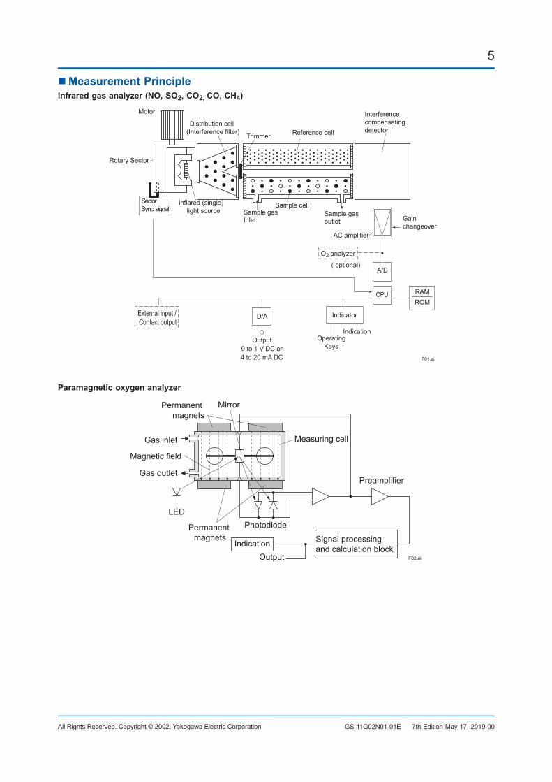
MeasurementPrincipleInfraredgasanalyzer(NO,SO2,CO2,CO,CH4)
Sample gas outlet
Sample cellSample gasInlet
Trimmer Reference cellDistribution cell
(Interference filter)
Inflared (single)light source
Motor
Rotary Sector
SectorSync. signal
O2 analyzer
( optional)A/D
CPU
IndicatorD/AExternal input / Contact output
RAMROM
Output0 to 1 V DC or4 to 20 mA DC
OperatingKeys
Indication
F01.ai
Interference compensatingdetector
Gain changeover
AC amplifier
Paramagneticoxygenanalyzer
OutputIndication Signal processing
and calculation block
PreamplifierGas outlet
Gas inlet Measuring cell
Mirror
Magnetic field
PhotodiodePermanent magnets
Permanent magnets
LED
F02.ai
7th Edition May 17, 2019-00
6
All Rights Reserved. Copyright © 2002, Yokogawa Electric Corporation GS 11G02N01-01E
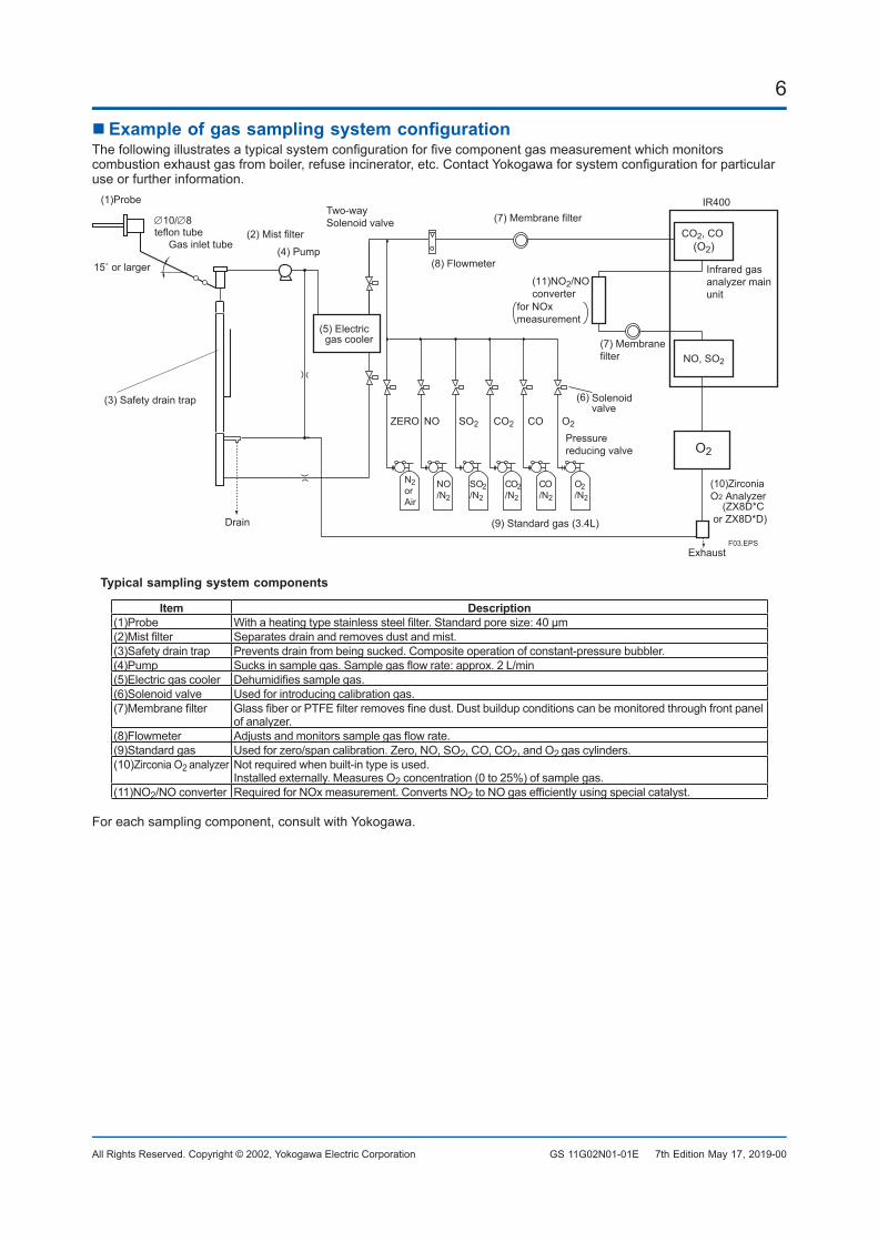
ExampleofgassamplingsystemconfigurationThefollowingillustratesatypicalsystemconfigurationforfivecomponentgasmeasurementwhichmonitorscombustionexhaustgasfromboiler,refuseincinerator,etc.ContactYokogawaforsystemconfigurationforparticularuse or further information.
O2
NO/N2
N2orAir
ZERO NO
SO2/N2
SO2
CO2/N2
CO2
CO/N2
CO
O2/N2
O2
CO2, CO (O2)
(1)Probe
Gas inlet tube
15˚ or larger(4) Pump
Solenoidvalve
(3) Safety drain trap
Drain
(5) Electric gas cooler
(8) Flowmeter
(7) Membrane filter
(9) Standard gas (3.4L)
Pressurereducing valve
(10)ZirconiaO2 Analyzer
Infrared gasanalyzer main unit
(11)NO2/NOconverter
for NOxmeasurement
NO, SO2
(7) Membranefilter
F03.EPS
(2) Mist filter
IR400
∅10/∅8teflon tube
Exhaust
Two-waySolenoid valve
(ZX8D*C or ZX8D*D)
(6)
Typicalsamplingsystemcomponents
Item Description(1)Probe Withaheatingtypestainlesssteelfilter.Standardporesize:40μm(2)Mistfilter Separatesdrainandremovesdustandmist.(3)Safety drain trap Preventsdrainfrombeingsucked.Compositeoperationofconstant-pressurebubbler.(4)Pump Sucksinsamplegas.Samplegasflowrate:approx.2L/min(5)Electricgascooler Dehumidifiessamplegas.(6)Solenoidvalve Used for introducing calibration gas.(7)Membranefilter GlassfiberorPTFEfilterremovesfinedust.Dustbuildupconditionscanbemonitoredthroughfrontpanel
of analyzer.(8)Flowmeter Adjustsandmonitorssamplegasflowrate.(9)Standardgas Used for zero/span calibration. Zero, NO, SO2, CO, CO2, and O2 gas cylinders.(10)Zirconia O2 analyzer Notrequiredwhenbuilt-intypeisused.
Installed externally. Measures O2concentration(0to25%)ofsamplegas.(11)NO2/NOconverter RequiredforNOxmeasurement.ConvertsNO2toNOgasefficientlyusingspecialcatalyst.
Foreachsamplingcomponent,consultwithYokogawa.
7th Edition May 17, 2019-00
7
All Rights Reserved. Copyright © 2002, Yokogawa Electric Corporation GS 11G02N01-01E
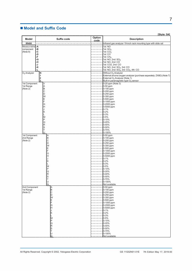
ModelandSuffixCode[Style:S4]
Model Suffixcode Optioncode Description
IR400 - - - - - - - - - - - - - - - - - - - - - - - - - - - - - - - - - - - - - - - - - - - - Infraredgasanalyzer19-inchrackmountingtypewithsliderailMeasurable component (Note8)
-A-B-C-D-F-G-H-J-K-L
- - - - - - - -- - - - - - - -- - - - - - - -- - - - - - - -- - - - - - - -- - - - - - - -- - - - - - - -- - - - - - - -- - - - - - - -- - - - - - - -
1st: NO1st: SO21st: CO21st: CO1st: CH41st: NO, 2nd: SO21st: NO, 2nd: CO1st: CO2, 2nd: CO1st: NO, 2nd: SO2, 3rd: CO1st: NO, 2nd: SO2, 3rd: CO2, 4th: CO
O2 Analyzer N123
- - - - - - - -- - - - - - - -- - - - - - - -- - - - - - - -
WithoutO2 AnalyzerExternalzirconaoxygenanalyzer(purchaseseparately:ZX8D)(Note7)External O2Analyzer(Note1)Built-in paramagnetic type O2 sensor
1st Component1st Range(Note2)
VABCDWEFGHJKLMPQRSTU
- - - - - - - -- - - - - - - -- - - - - - - -- - - - - - - -- - - - - - - -- - - - - - - -- - - - - - - -- - - - - - - -- - - - - - - -- - - - - - - -- - - - - - - -- - - - - - - -- - - - - - - -- - - - - - - -- - - - - - - -- - - - - - - -- - - - - - - -- - - - - - - -- - - - - - - -- - - - - - - -
0-20ppm(Note3)0-50 ppm0-100 ppm0-200 ppm0-250 ppm0-300 ppm0-500 ppm0-1000 ppm0-2000 ppm0-5000 ppm0-1%0-2%0-3%0-5%0-10%0-20%0-40%0-50%0-70%0-100%
1st Component2nd Range(Note2)
ABCDWEFGHJKLMPQRSTUN
- - - - - - - -- - - - - - - -- - - - - - - -- - - - - - - -- - - - - - - -- - - - - - - -- - - - - - - -- - - - - - - -- - - - - - - -- - - - - - - -- - - - - - - -- - - - - - - -- - - - - - - -- - - - - - - -- - - - - - - -- - - - - - - -- - - - - - - -- - - - - - - -- - - - - - - -- - - - - - - -
0-50 ppm0-100 ppm0-200 ppm0-250 ppm0-300 ppm0-500 ppm0-1000 ppm0-2000 ppm0-5000 ppm0-1%0-2%0-3%0-5%0-10%0-20%0-40%0-50%0-70%0-100%Notavailable
2nd Component1st Range(Note2)
ABCDWEFGHJKLMPQRSTUN
- - - - - - - -- - - - - - - -- - - - - - - -- - - - - - - -- - - - - - - -- - - - - - - -- - - - - - - -- - - - - - - -- - - - - - - -- - - - - - - -- - - - - - - -- - - - - - - -- - - - - - - -- - - - - - - -- - - - - - - -- - - - - - - -- - - - - - - -- - - - - - - -- - - - - - - -- - - - - - - -
0-50 ppm0-100 ppm0-200 ppm0-250 ppm0-300 ppm0-500 ppm0-1000 ppm0-2000 ppm0-5000 ppm0-1%0-2%0-3%0-5%0-10%0-20%0-40%0-50%0-70%0-100%Notavailable
7th Edition May 17, 2019-00
8
All Rights Reserved. Copyright © 2002, Yokogawa Electric Corporation GS 11G02N01-01E
[Style:S4]Model Suffixcode Option
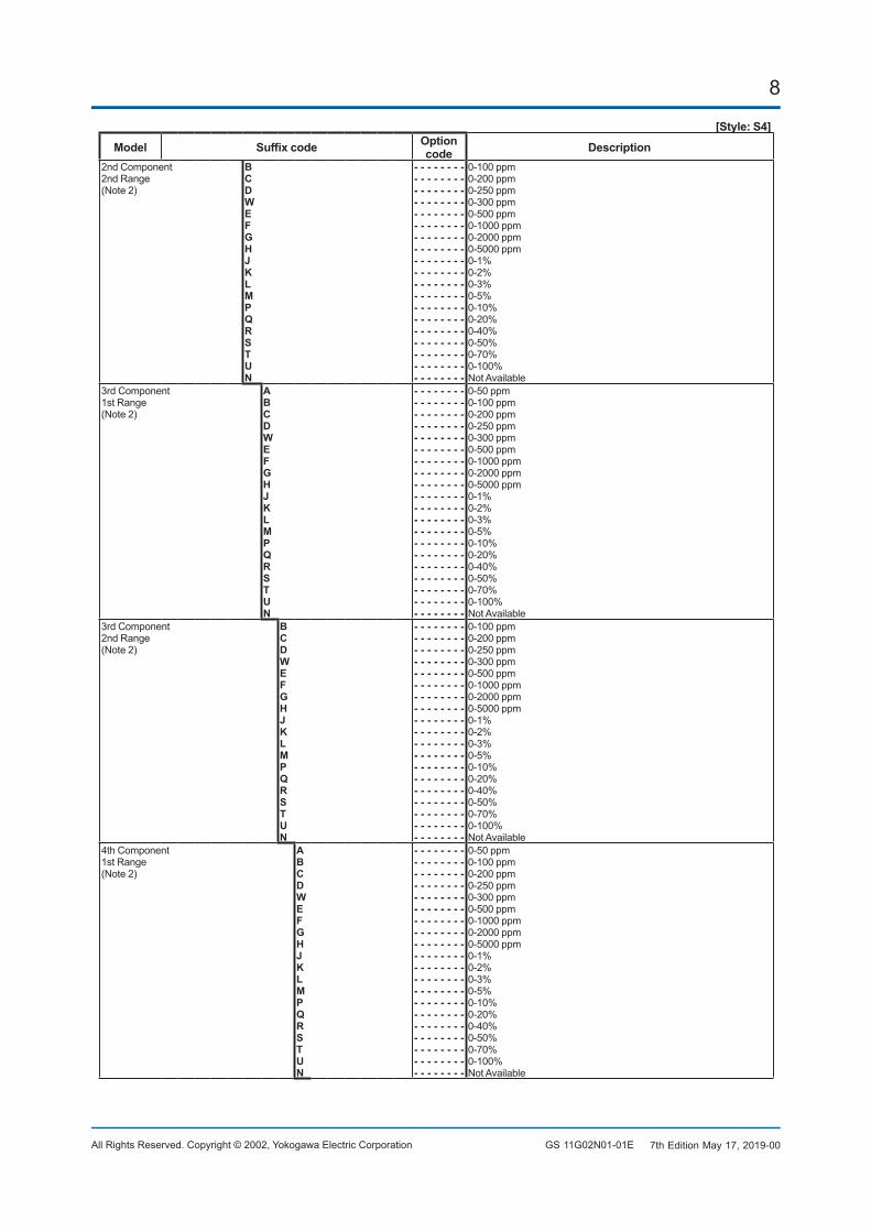
code Description2nd Component2nd Range(Note2)
BCDWEFGHJKLMPQRSTUN
- - - - - - - -- - - - - - - -- - - - - - - -- - - - - - - -- - - - - - - -- - - - - - - -- - - - - - - -- - - - - - - -- - - - - - - -- - - - - - - -- - - - - - - -- - - - - - - -- - - - - - - -- - - - - - - -- - - - - - - -- - - - - - - -- - - - - - - -- - - - - - - -- - - - - - - -
0-100 ppm0-200 ppm0-250 ppm0-300 ppm0-500 ppm0-1000 ppm0-2000 ppm0-5000 ppm0-1%0-2%0-3%0-5%0-10%0-20%0-40%0-50%0-70%0-100%NotAvailable
3rd Component1st Range(Note2)
ABCDWEFGHJKLMPQRSTUN
- - - - - - - -- - - - - - - -- - - - - - - -- - - - - - - -- - - - - - - -- - - - - - - -- - - - - - - -- - - - - - - -- - - - - - - -- - - - - - - -- - - - - - - -- - - - - - - -- - - - - - - -- - - - - - - -- - - - - - - -- - - - - - - -- - - - - - - -- - - - - - - -- - - - - - - -- - - - - - - -
0-50 ppm0-100 ppm0-200 ppm0-250 ppm0-300 ppm0-500 ppm0-1000 ppm0-2000 ppm0-5000 ppm0-1%0-2%0-3%0-5%0-10%0-20%0-40%0-50%0-70%0-100%NotAvailable
3rd Component2nd Range(Note2)
BCDWEFGHJKLMPQRSTUN
- - - - - - - -- - - - - - - -- - - - - - - -- - - - - - - -- - - - - - - -- - - - - - - -- - - - - - - -- - - - - - - -- - - - - - - -- - - - - - - -- - - - - - - -- - - - - - - -- - - - - - - -- - - - - - - -- - - - - - - -- - - - - - - -- - - - - - - -- - - - - - - -- - - - - - - -
0-100 ppm0-200 ppm0-250 ppm0-300 ppm0-500 ppm0-1000 ppm0-2000 ppm0-5000 ppm0-1%0-2%0-3%0-5%0-10%0-20%0-40%0-50%0-70%0-100%NotAvailable
4th Component1st Range(Note2)
ABCDWEFGHJKLMPQRSTUN
- - - - - - - -- - - - - - - -- - - - - - - -- - - - - - - -- - - - - - - -- - - - - - - -- - - - - - - -- - - - - - - -- - - - - - - -- - - - - - - -- - - - - - - -- - - - - - - -- - - - - - - -- - - - - - - -- - - - - - - -- - - - - - - -- - - - - - - -- - - - - - - -- - - - - - - -- - - - - - - -
0-50 ppm0-100 ppm0-200 ppm0-250 ppm0-300 ppm0-500 ppm0-1000 ppm0-2000 ppm0-5000 ppm0-1%0-2%0-3%0-5%0-10%0-20%0-40%0-50%0-70%0-100%NotAvailable
7th Edition May 17, 2019-00
9
All Rights Reserved. Copyright © 2002, Yokogawa Electric Corporation GS 11G02N01-01E
[Style:S4]Model Suffixcode Option
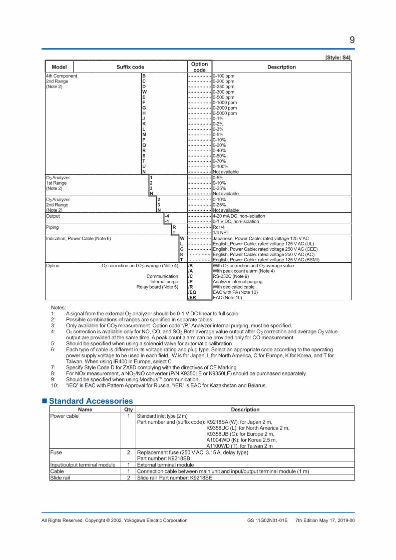
code Description4th Component2nd Range(Note2)
BCDWEFGHJKLMPQRSTUN
- - - - - - - -- - - - - - - -- - - - - - - -- - - - - - - -- - - - - - - -- - - - - - - -- - - - - - - -- - - - - - - -- - - - - - - -- - - - - - - -- - - - - - - -- - - - - - - -- - - - - - - -- - - - - - - -- - - - - - - -- - - - - - - -- - - - - - - -- - - - - - - -- - - - - - - -
0-100 ppm0-200 ppm0-250 ppm0-300 ppm0-500 ppm0-1000 ppm0-2000 ppm0-5000 ppm0-1%0-2%0-3%0-5%0-10%0-20%0-40%0-50%0-70%0-100%Notavailable
O2 Analyzer1st Range(Note2)
123N
- - - - - - - -- - - - - - - -- - - - - - - -- - - - - - - -
0-5%0-10%0-25%Notavailable
O2 Analyzer2nd Range(Note2)
23N
- - - - - - - -- - - - - - - -- - - - - - - -
0-10%0-25%Notavailable
Output -4-1
- - - - - - - -- - - - - - - -
4-20 mA DC, non-isolation0-1 V DC, non-isolation
Piping RT
- - - - - - - -- - - - - - - -
Rc1/41/4 NPT
Indication,PowerCable(Note6) WLCKT
- - - - - - - -- - - - - - - -- - - - - - - -- - - - - - - - - - - - - -
Japanese,PowerCable:ratedvoltage125VACEnglish,PowerCable:ratedvoltage125VAC(UL)English,PowerCable:ratedvoltage250VAC(CEE)English,PowerCable:ratedvoltage250VAC(KC)English,PowerCable:ratedvoltage125VAC(BSMI)
Option O2 correction and O2 avarage(Note4)
CommunicationInternal purge
Relayboard(Note5)
/K/A/C/P/R/EQ/ER
WithO2 correction and O2 averagevalueWithpeakcountalarm(Note4)RS-232C(Note9)Analyzer internal purgingWithdedicatedcableEACwithPA(Note10)EAC(Note10)
Notes:1: A signal from the external O2 analyzer should be 0-1 V DC linear to full scale.2: Possiblecombinationsofrangesarespecifiedinseparatetables.3: OnlyavailableforCO2 measurement.Optioncode“/P,”Analyzerinternalpurging,mustbespecified.4: O2correctionisavailableonlyforNO,CO,andSO2BothaveragevalueoutputafterO2 correctionandaverageO2value
outputareprovidedatthesametime.ApeakcountalarmcanbeprovidedonlyforCOmeasurement.5: Shouldbespecifiedwhenusingasolenoidvalveforautomaticcalibration.6: Eachtypeofcableisdifferentinitsvoltageratingandplugtype.Selectanappropriatecodeaccordingtotheoperating
powersupplyvoltagetobeusedineachfield.WisforJapan,LforNorthAmerica,CforEurope,KforKorea,andTforTaiwan.WhenusingIR400inEurope,selectC.
7: SpecifyStyleCodeDforZX8DcomplyingwiththedirectivesofCEMarking8: For NOx measurement, a NO2/NOconverter(P/NK9350LEorK9350LF)shouldbepurchasedseparately.9: ShouldbespecifiedwhenusingModbusTM communication.10: “/EQ”isEACwithPatternApprovalforRussia.“/ER”isEACforKazakhstanandBelarus.
StandardAccessoriesName Qty Description
Powercable 1 Standardinlettype(2m)Partnumberand(suffixcode):K9218SA(W):forJapan2m,
K9358UC(L):forNorthAmerica2m, K9358UB(C):forEurope2m, A1004WD(K):forKorea2.5m, A1100WD(T):forTaiwan2m
Fuse 2 Replacementfuse(250VAC,3.15A,delaytype)Part number: K9218SB
Input/output terminal module 1 External terminal moduleCable 1 Connectioncablebetweenmainunitandinput/outputterminalmodule(1m)Slide rail 2 Slide rail Part number: K9218SE
7th Edition May 17, 2019-00
10
All Rights Reserved. Copyright © 2002, Yokogawa Electric Corporation GS 11G02N01-01E 7th Edition May 17, 2019-00
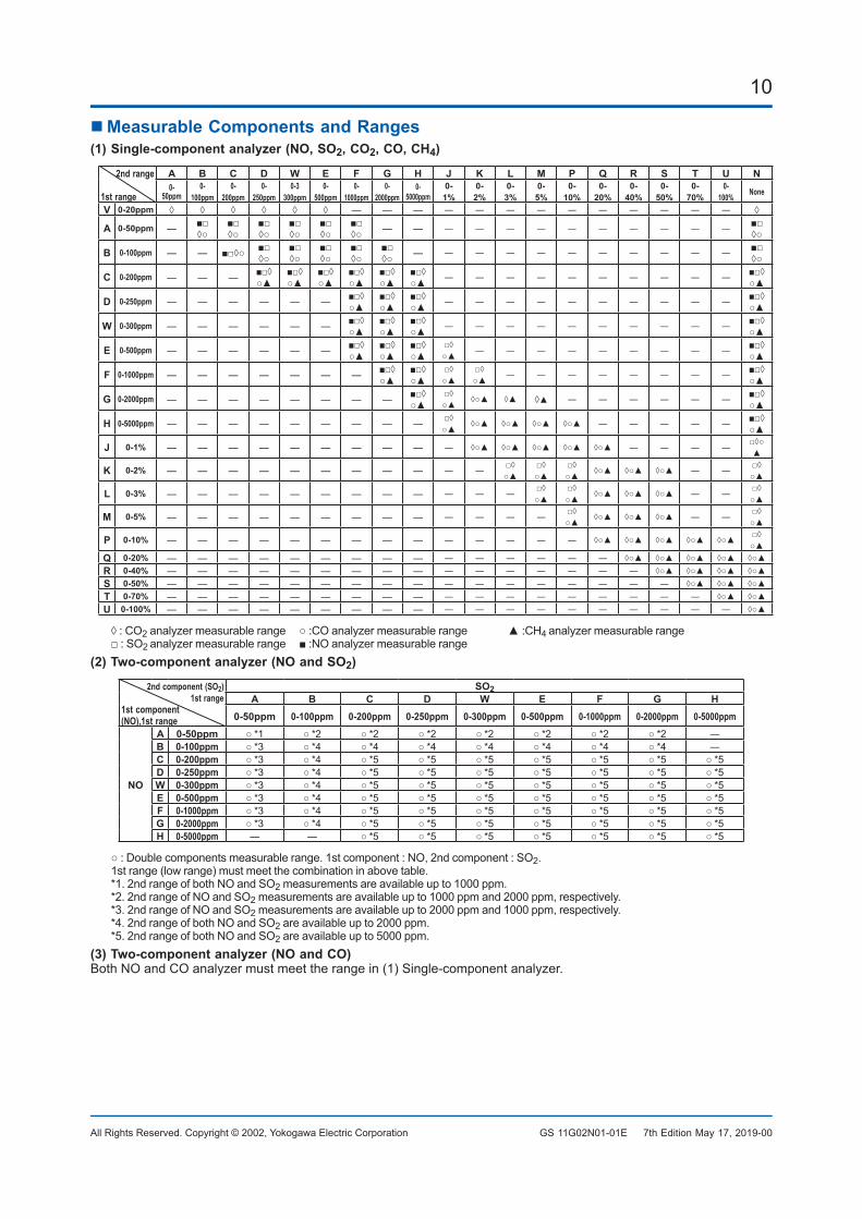
MeasurableComponentsandRanges(1)Single-componentanalyzer(NO,SO2,CO2,CO,CH4)
2nd range
1st range
A B C D W E F G H J K L M P Q R S T U N0-
50ppm0-
100ppm0-
200ppm0-
250ppm0-3
300ppm0-
500ppm0-
1000ppm0-
2000ppm0-
5000ppm0-1%
0-2%
0-3%
0-5%
0-10%
0-20%
0-40%
0-50%
0-70%
0-100% None
V 0-20ppm ◊ ◊ ◊ ◊ ◊ ◊ ― ― ― ― ― ― ― ― ― ― ― ― ― ◊
A 0-50ppm ― ■□◊○
■□◊○
■□◊○
■□◊○
■□◊○
■□◊○ ― ― ― ― ― ― ― ― ― ― ― ― ■□
◊○
B 0-100ppm ― ― ■□◊○ ■□◊○
■□◊○
■□◊○
■□◊○
■□◊○ ― ― ― ― ― ― ― ― ― ― ― ■□
◊○
C 0-200ppm ― ― ― ■□◊○▲
■□◊○▲
■□◊○▲
■□◊○▲
■□◊○▲
■□◊○▲ ― ― ― ― ― ― ― ― ― ― ■□◊
○▲
D 0-250ppm ― ― ― ― ― ― ■□◊○▲
■□◊○▲
■□◊○▲ ― ― ― ― ― ― ― ― ― ― ■□◊
○▲
W 0-300ppm ― ― ― ― ― ― ■□◊○▲
■□◊○▲
■□◊○▲ ― ― ― ― ― ― ― ― ― ― ■□◊
○▲
E 0-500ppm ― ― ― ― ― ― ■□◊○▲
■□◊○▲
■□◊○▲
□◊○▲ ― ― ― ― ― ― ― ― ― ■□◊
○▲
F 0-1000ppm ― ― ― ― ― ― ― ■□◊○▲
■□◊○▲
□◊○▲
□◊○▲ ― ― ― ― ― ― ― ― ■□◊
○▲
G 0-2000ppm ― ― ― ― ― ― ― ― ■□◊○▲
□◊○▲ ◊○▲ ◊▲ ◊▲ ― ― ― ― ― ― ■□◊
○▲
H 0-5000ppm ― ― ― ― ― ― ― ― ― □◊○▲ ◊○▲ ◊○▲ ◊○▲ ◊○▲ ― ― ― ― ― ■□◊
○▲
J 0-1% ― ― ― ― ― ― ― ― ― ― ◊○▲ ◊○▲ ◊○▲ ◊○▲ ◊○▲ ― ― ― ― □◊○▲
K 0-2% ― ― ― ― ― ― ― ― ― ― ― □◊○▲
□◊○▲
□◊○▲ ◊○▲ ◊○▲ ◊○▲ ― ― □◊
○▲
L 0-3% ― ― ― ― ― ― ― ― ― ― ― ― □◊○▲
□◊○▲ ◊○▲ ◊○▲ ◊○▲ ― ― □◊
○▲
M 0-5% ― ― ― ― ― ― ― ― ― ― ― ― ― □◊○▲ ◊○▲ ◊○▲ ◊○▲ ― ― □◊
○▲
P 0-10% ― ― ― ― ― ― ― ― ― ― ― ― ― ― ◊○▲ ◊○▲ ◊○▲ ◊○▲ ◊○▲ □◊○▲
Q 0-20% ― ― ― ― ― ― ― ― ― ― ― ― ― ― ― ◊○▲ ◊○▲ ◊○▲ ◊○▲ ◊○▲R 0-40% ― ― ― ― ― ― ― ― ― ― ― ― ― ― ― ― ◊○▲ ◊○▲ ◊○▲ ◊○▲S 0-50% ― ― ― ― ― ― ― ― ― ― ― ― ― ― ― ― ― ◊○▲ ◊○▲ ◊○▲T 0-70% ― ― ― ― ― ― ― ― ― ― ― ― ― ― ― ― ― ― ◊○▲ ◊○▲U 0-100% ― ― ― ― ― ― ― ― ― ― ― ― ― ― ― ― ― ― ― ◊○▲
◊:CO2analyzermeasurablerange ○:COanalyzermeasurablerange ▲:CH4 analyzer measurable range□:SO2 analyzermeasurablerange ■:NOanalyzermeasurablerange
(2)Two-componentanalyzer(NOandSO2)
2ndcomponent(SO2)1st range
1stcomponent(NO),1strange
SO2A B C D W E F G H
0-50ppm 0-100ppm 0-200ppm 0-250ppm 0-300ppm 0-500ppm 0-1000ppm 0-2000ppm 0-5000ppm
NO
A 0-50ppm ○*1 ○*2 ○*2 ○*2 ○*2 ○*2 ○*2 ○*2 ―B 0-100ppm ○*3 ○*4 ○*4 ○*4 ○*4 ○*4 ○*4 ○*4 ―C 0-200ppm ○*3 ○*4 ○*5 ○*5 ○*5 ○*5 ○*5 ○*5 ○*5D 0-250ppm ○*3 ○*4 ○*5 ○*5 ○*5 ○*5 ○*5 ○*5 ○*5W 0-300ppm ○*3 ○*4 ○*5 ○*5 ○*5 ○*5 ○*5 ○*5 ○*5E 0-500ppm ○*3 ○*4 ○*5 ○*5 ○*5 ○*5 ○*5 ○*5 ○*5F 0-1000ppm ○*3 ○*4 ○*5 ○*5 ○*5 ○*5 ○*5 ○*5 ○*5G 0-2000ppm ○*3 ○*4 ○*5 ○*5 ○*5 ○*5 ○*5 ○*5 ○*5H 0-5000ppm ― ― ○*5 ○*5 ○*5 ○*5 ○*5 ○*5 ○*5
○:Doublecomponentsmeasurablerange.1stcomponent:NO,2ndcomponent:SO2.1strange(lowrange)mustmeetthecombinationinabovetable.*1. 2nd range of both NO and SO2measurementsareavailableupto1000ppm.*2. 2nd range of NO and SO2measurementsareavailableupto1000ppmand2000ppm,respectively.*3. 2nd range of NO and SO2measurementsareavailableupto2000ppmand1000ppm,respectively.*4. 2nd range of both NO and SO2areavailableupto2000ppm.*5. 2nd range of both NO and SO2areavailableupto5000ppm.
(3)Two-componentanalyzer(NOandCO)BothNOandCOanalyzermustmeettherangein(1)Single-componentanalyzer.
11
All Rights Reserved. Copyright © 2002, Yokogawa Electric Corporation GS 11G02N01-01E
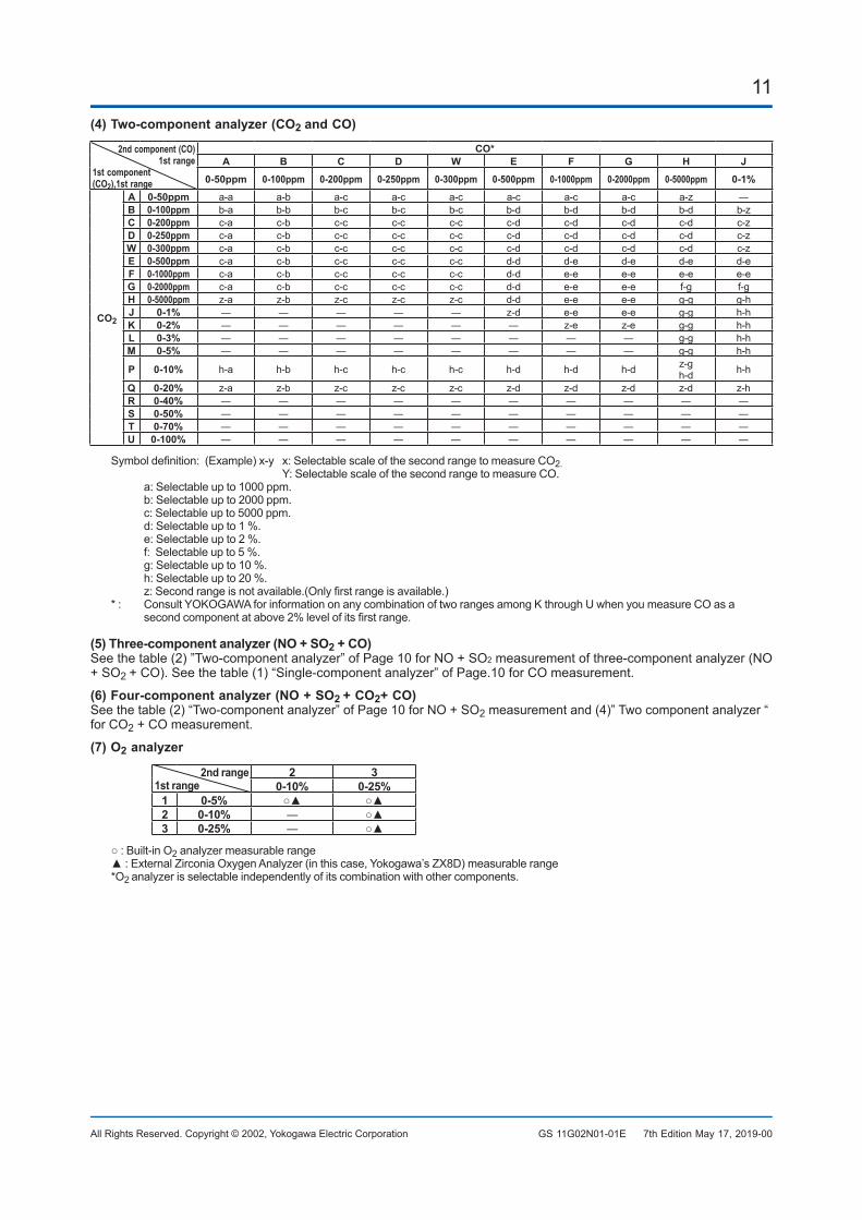
(4)Two-componentanalyzer(CO2 andCO)
2ndcomponent(CO) 1st range
1stcomponent(CO2),1strange
CO*A B C D W E F G H J
0-50ppm 0-100ppm 0-200ppm 0-250ppm 0-300ppm 0-500ppm 0-1000ppm 0-2000ppm 0-5000ppm 0-1%
CO2
A 0-50ppm a-a a-b a-c a-c a-c a-c a-c a-c a-z ―B 0-100ppm b-a b-b b-c b-c b-c b-d b-d b-d b-d b-zC 0-200ppm c-a c-b c-c c-c c-c c-d c-d c-d c-d c-zD 0-250ppm c-a c-b c-c c-c c-c c-d c-d c-d c-d c-zW 0-300ppm c-a c-b c-c c-c c-c c-d c-d c-d c-d c-zE 0-500ppm c-a c-b c-c c-c c-c d-d d-e d-e d-e d-eF 0-1000ppm c-a c-b c-c c-c c-c d-d e-e e-e e-e e-eG 0-2000ppm c-a c-b c-c c-c c-c d-d e-e e-e f-g f-gH 0-5000ppm z-a z-b z-c z-c z-c d-d e-e e-e g-g g-hJ 0-1% ― ― ― ― ― z-d e-e e-e g-g h-hK 0-2% ― ― ― ― ― ― z-e z-e g-g h-hL 0-3% ― ― ― ― ― ― ― ― g-g h-hM 0-5% ― ― ― ― ― ― ― ― g-g h-h
P 0-10% h-a h-b h-c h-c h-c h-d h-d h-d z-gh-d h-h
Q 0-20% z-a z-b z-c z-c z-c z-d z-d z-d z-d z-hR 0-40% ― ― ― ― ― ― ― ― ― ―S 0-50% ― ― ― ― ― ― ― ― ― ―T 0-70% ― ― ― ― ― ― ― ― ― ―U 0-100% ― ― ― ― ― ― ― ― ― ―
Symboldefinition:(Example)x-yx:SelectablescaleofthesecondrangetomeasureCO2. Y: Selectable scale of the second range to measure CO.
a: Selectable up to 1000 ppm. b: Selectable up to 2000 ppm. c: Selectable up to 5000 ppm. d: Selectable up to 1 %. e: Selectable up to 2 %. f: Selectable up to 5 %. g: Selectable up to 10 %. h: Selectable up to 20 %. z:Secondrangeisnotavailable.(Onlyfirstrangeisavailable.)*: ConsultYOKOGAWAforinformationonanycombinationoftworangesamongKthroughUwhenyoumeasureCOasa
secondcomponentatabove2%levelofitsfirstrange.
(5)Three-componentanalyzer(NO+SO2+CO)Seethetable(2)”Two-componentanalyzer”ofPage10forNO+SO2measurementofthree-componentanalyzer(NO+SO2 +CO).Seethetable(1)“Single-componentanalyzer”ofPage.10forCOmeasurement.
(6)Four-componentanalyzer(NO+SO2 +CO2+CO)Seethetable(2)“Two-componentanalyzer”ofPage10forNO+SO2measurementand(4)”Twocomponentanalyzer“for CO2+COmeasurement.
(7)O2 analyzer
2nd range1st range
2 30-10% 0-25%
1 0-5% ○▲ ○▲2 0-10% ― ○▲3 0-25% ― ○▲
○:Built-inO2 analyzer measurable range▲:ExternalZirconiaOxygenAnalyzer(inthiscase,Yokogawa’sZX8D)measurablerange*O2 analyzerisselectableindependentlyofitscombinationwithothercomponents.
7th Edition May 17, 2019-00
12
All Rights Reserved. Copyright © 2002, Yokogawa Electric Corporation GS 11G02N01-01E
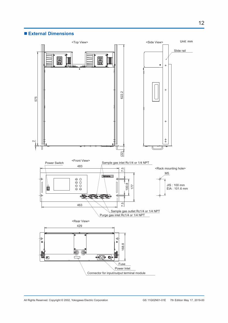
ExternalDimensions
(22)
622.
2
575
2
463
177
7.5
7.5
100.
8
429
168.
8
483
M5
Unit: mm
Slide rail
<Side View><Top View>
<Front View>Sample gas inlet Rc1/4 or 1/4 NPT
Purge gas inlet Rc1/4 or 1/4 NPT Sample gas outlet Rc1/4 or 1/4 NPT
Power Inlet
<Rear View>
Power Switch
<Rack mounting hole>
JIS : 100 mmEIA : 101.6 mm
Connector for input/output terminal module
Fuse
7th Edition May 17, 2019-00
13
All Rights Reserved. Copyright © 2002, Yokogawa Electric Corporation GS 11G02N01-01E
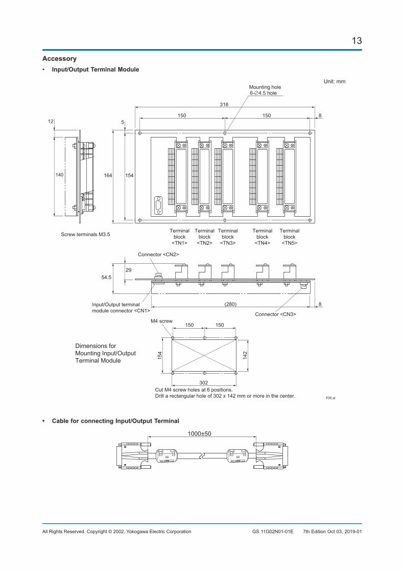
Accessory• Input/OutputTerminalModule
140
12
164 154
5
54.529
316
6-∅4.5 hole
150 150 8
(280) 8
Terminalblock
<TN1>
Terminalblock
<TN2>
Terminalblock
<TN3>
Terminalblock
<TN4>
Terminalblock
<TN5>
Connector <CN3>
Screw terminals M3.5
Input/Output terminal module connector <CN1>
Dimensions for Mounting Input/Output Terminal Module
Mounting hole
Connector <CN2>
302
150 150
154
142
M4 screw
Cut M4 screw holes at 6 positions.Drill a rectangular hole of 302 x 142 mm or more in the center. F05.ai
Unit: mm
• CableforconnectingInput/OutputTerminal
1000±50
7th Edition Oct 03, 2019-01
14
All Rights Reserved. Copyright © 2002, Yokogawa Electric Corporation GS 11G02N01-01E
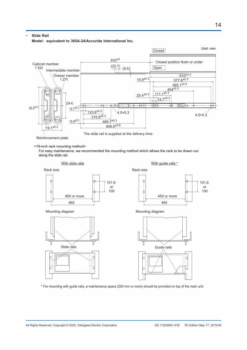
• Slide Rail Model:equivalentto305A-24/AccurideInternationalInc.
632±3
(22.7)(9.5)
123.8±0.3
610±0.3 577.8±0.3
565.1±0.3
454±0.3
111.1±0.3
12.7±0.3 35.3±0.3(24.4)
15.9±0.5 315.8±0.3
466.7±0.3
19.1±0.3 606.6±0.8
4.5×5.34.5×5.3
12.7±0.3
25.4±0.3
15.9±0.3
Closed
OpenClosed position flush or underCabinet member
1.52t
Drawer member 1.27t
Intermediate member
Reinforcement plate The slide rail is supplied at the delivery time.
Unit: mm
* For mounting with guide rails, a maintenance space (200 mm or more) should be provided on top of the main unit.
450 or more
Rack size
With slide rails With guide rails *
Rack size
450 or more
101.6 or
100
Mounting diagram Mounting diagram
Guide railsSlide rails
<19-inch rack mounting method>For easy maintenance, we recommended the mounting method which allows the rack to be drawn out along the slide rail.
101.6 or
100
465 465
7th Edition May 17, 2019-00
15
All Rights Reserved. Copyright © 2002, Yokogawa Electric Corporation GS 11G02N01-01E
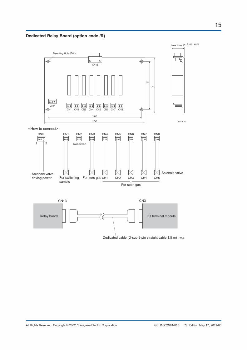
DedicatedRelayBoard(optioncode/R)
CN1CN9
CN2 CN3 CN4 CN5
CN13
CN6 CN7 CN8
75
65
150
140
Less than 15
∅4.5
Unit: mm
F10-E.ai
Mounting Hole
<Howtoconnect>CN1CN9
Solenoid valvedriving power
Solenoid valve
CN2
CN13 CN3
Reserved
For switchingsample
CN3
For zero gas
Relay board
Dedicated cable (D-sub 9-pin straight cable 1.5 m)
For span gas
CN4 CN5 CN6 CN7 CN8
CH1 CH2 CH3 CH4 CH5
F11.ai
I/O terminal module
1 3
7th Edition May 17, 2019-00
16
All Rights Reserved. Copyright © 2002, Yokogawa Electric Corporation GS 11G02N01-01E
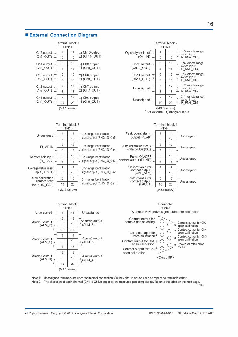
ExternalConnectionDiagramTerminal block 1
<TN1>11
12
13
14
15
16
17
18
19
20
1
2
3
4
5
6
7
8
9
10
(M3.5 screw)
Ch9 output(Ch9_OUT)
Ch10 output(Ch10_OUT)
Ch8 output(Ch8_OUT)
Ch7 output(Ch7_OUT)
Ch6 output(Ch6_OUT)
Ch1 output(Ch1_OUT)
Ch2 output(Ch2_OUT)
Ch3 output(Ch3_OUT)
Ch4 output(Ch4_OUT)
Ch5 output(Ch5_OUT) +
Terminal block 2<TN2>
11
12
13
14
15
16
17
18
19
20
1
2
3
4
5
6
7
8
9
10
(M3.5 screw)
Ch4 remote rangeswitch input(R_RNG_Ch4)
Ch5 remote rangeswitch input(R_RNG_Ch5)
Ch3 remote rangeswitch input(R_RNG_Ch3)Ch2 remote rangeswitch input(R_RNG_Ch2)Ch1 remote rangeswitch input(R_RNG_Ch1)
Ch12 output(Ch12_OUT)
Ch11 output(Ch11_OUT)
Unassigned
Unassigned
O2 analyzer input(O2 _IN)
*
*
Terminal block 3<TN3>
11
12
13
14
15
16
17
18
19
20
1
2
3
4
5
6
7
8
9
10
(M3.5 screw)
Ch4 range identificationsignal output (RNG_ID_Ch4)
Ch5 range identificationsignal output (RNG_ID_Ch5)
Ch3 range identificationsignal output (RNG_ID_Ch3)
Ch2 range identificationsignal output (RNG_ID_Ch2)
Ch1 range identificationsignal output (RNG_ID_Ch1)
Auto calibration remote start
input (R_CAL)
Average value reset input (RESET)
Remote hold input (R_HOLD)
PUMP IN
Unassigned
Terminal block 5<TN5>
11
12
13
14
15
16
17
18
19
20
1
2
3
4
5
6
7
8
9
10
(M3.5 screw)
Unassigned
Alarm6 output (ALM_6)
Alarm5 output (ALM_5)
Alarm4 output(ALM_4)
Alarm3 output (ALM_3)
Alarm2 output (ALM_2)
Alarm1 output (ALM_1)
Unassigned
Terminal block 4<TN4>
11
12
13
14
15
16
17
18
19
20
1
2
3
4
5
6
7
8
9
10
(M3.5 screw)
Unassigned
Unassigned
Unassigned
Auto calibration statuscontact output (CAL)
Calibration errorcontact output
(CAL_ALM)Unassigned
Unassigned
Note 1: Unassigned terminals are used for internal connection. So they should not be used as repeating terminals either. Note 2: The allocation of each channel (Ch1 to Ch12) depends on measured gas components. Refer to the table on the next page.
For external O2 analyzer input.
Instrument errorcontact output
(FAULT)
Pump ON/OFF contact output (PUMP)
Peak count alarm output (PEAK)
Connector<CN3>
Solenoid valve drive signal output for calibration
<D-sub 9P>
Contact output for zero calibration
Contact output forsample gas selecting
Contact output for Ch1 span calibration
Contact output for Ch2 span calibration
Contact output for Ch3 span calibrationContact output for Ch4 span calibration Contact output for Ch5 span calibration Power for relay drive5V DC
1
2
3
4
5
6
7
8
9
F08.ai
-
+-
+-
+-
+-
+-
+-
+-
+-
+-
+-
+-
+-
+-
+-
+-
+-
+-
7th Edition May 17, 2019-00
17
All Rights Reserved. Copyright © 2002, Yokogawa Electric Corporation GS 11G02N01-01E
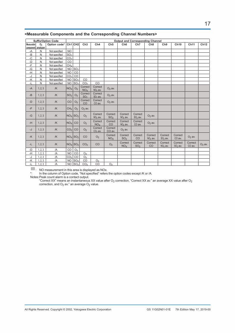
<MeasurableComponentsandtheCorrespondingChannelNumbers>Suffix/OptionCode OutputandCorrespondingChannel
Measurable component
O2 analyzer
Optioncode* Ch1 CH2 Ch3 Ch4 Ch5 Ch6 Ch7 Ch8 Ch9 Ch10 Ch11 Ch12
-A N Notspecified NO-B N Notspecified SO2-C N Notspecified CO2-D N Notspecified CO-F N Notspecified CH4-G N Notspecified NO SO2-H N Notspecified NO CO-J N Notspecified CO2 CO-K N Notspecified NO SO2 CO-L N Notspecified NO SO2 CO2 CO
-A 1, 2, 3 /K NOX O2Correct
NOXCorrect NOXav.
O2av.
-B 1, 2, 3 /K SO2 O2Correct
SO2Correct SO2av.
O2av.
-D 1, 2, 3 /K CO O2Correct
COCorrect COav. O2av.
-F 1, 2, 3 /K CH4 O2 O2av.
-G 1, 2, 3 /K NOX SO2 O2Correct NOXav.
Correct SO2
Correct NOXav.
Correct SO2av.
O2av.
-H 1, 2, 3 /K NOX CO O2Correct
NOXCorrect
COCorrect NOXav.
Correct COav. O2av.
-J 1, 2, 3 /K CO2 CO O2Correct CO2av.
Correct COav. O2av.
-K 1, 2, 3 /K NOX SO2 CO O2Correct
NOXCorrect
SO2Correct
COCorrect NOXav.
Correct SO2av.
Correct COav. O2av.
-L 1, 2, 3 /K NOX SO2 CO2 CO O2Correct
NOXCorrect
SO2Correct
COCorrect NOXav.
Correct SO2av.
Correct COav. O2av.
-D 1, 2, 3 /A CO O2-H 1, 2, 3 /A NO CO O2-J 1, 2, 3 /A CO2 CO O2-K 1, 2, 3 /A NO SO2 CO O2-L 1, 2, 3 /A NO SO2 CO2 CO O2
: NO measurement in this area is displayed as NOx.*: InthecolumnofOptioncode,“Notspecified”referstheoptioncodesexcept/Kor/A.Notes: Peak count alarm is a contact output. “CorrectXX”meansaninstantaneousXXvalueafterO2correction,“CorrectXXav.”anaverageXXvalueafterO2
correction, and O2av.”anaverageO2value.
7th Edition May 17, 2019-00
18
All Rights Reserved. Copyright © 2002, Yokogawa Electric Corporation GS 11G02N01-01E
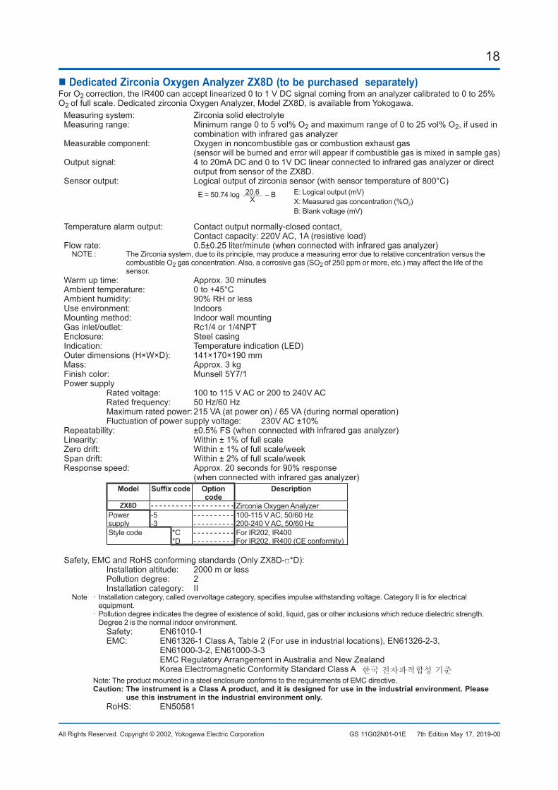
DedicatedZirconiaOxygenAnalyzerZX8D(tobepurchasedseparately)For O2 correction, the IR400 can accept linearized 0 to 1 V DC signal coming from an analyzer calibrated to 0 to 25% O2 offullscale.DedicatedzirconiaOxygenAnalyzer,ModelZX8D,isavailablefromYokogawa.
Measuring system: Zirconia solid electrolyteMeasuringrange: Minimumrange0to5vol%O2andmaximumrangeof0to25vol%O2, if used in
combinationwithinfraredgasanalyzerMeasurable component: Oxygen in noncombustible gas or combustion exhaust gas
(sensorwillbeburnedanderrorwillappearifcombustiblegasismixedinsamplegas)Output signal: 4 to 20mA DC and 0 to 1V DC linear connected to infrared gas analyzer or direct
outputfromsensoroftheZX8D.Sensoroutput: Logicaloutputofzirconiasensor(withsensortemperatureof800°C)
E = 50.74 log 20.6X – B E: Logical output (mV)
X: Measured gas concentration (%O2)B: Blank voltage (mV)
Temperature alarm output: Contact output normally-closed contact, Contactcapacity:220VAC,1A(resistiveload)
Flowrate: 0.5±0.25liter/minute(whenconnectedwithinfraredgasanalyzer)NOTE: TheZirconiasystem,duetoitsprinciple,mayproduceameasuringerrorduetorelativeconcentrationversusthe
combustible O2gasconcentration.Also,acorrosivegas(SO2 of250ppmormore,etc.)mayaffectthelifeofthesensor.
Warmuptime: Approx.30minutesAmbienttemperature: 0to+45°CAmbient humidity: 90% RH or lessUseenvironment: IndoorsMountingmethod: IndoorwallmountingGas inlet/outlet: Rc1/4 or 1/4NPTEnclosure: Steel casingIndication: Temperatureindication(LED)Outerdimensions(H×W×D): 141×170×190mmMass: Approx. 3 kgFinish color: Munsell 5Y7/1Powersupply Ratedvoltage: 100to115VACor200to240VAC Ratedfrequency: 50Hz/60Hz Maximumratedpower:215VA(atpoweron)/65VA(duringnormaloperation) Fluctuationofpowersupplyvoltage: 230VAC±10%Repeatability: ±0.5%FS(whenconnectedwithinfraredgasanalyzer)Linearity: Within±1%offullscaleZerodrift: Within±1%offullscale/weekSpandrift: Within±2%offullscale/weekResponse speed: Approx. 20 seconds for 90% response
(whenconnectedwithinfraredgasanalyzer)Model Suffixcode Option
codeDescription
ZX8D - - - - - - - - - - - - - - - - - - - - Zirconia Oxygen AnalyzerPowersupply
-5-3
- - - - - - - - - -- - - - - - - - - -
100-115 V AC, 50/60 Hz200-240 V AC, 50/60 Hz
Style code *C*D
- - - - - - - - - -- - - - - - - - - -
For IR202, IR400ForIR202,IR400(CEconformity)
Safety,EMCandRoHSconformingstandards(OnlyZX8D-□*D): Installation altitude: 2000 m or less Pollution degree: 2 Installation category: II Note · Installationcategory,calledovervoltagecategory,specifiesimpulsewithstandingvoltage.CategoryIIisforelectrical
equipment. ·Pollutiondegreeindicatesthedegreeofexistenceofsolid,liquid,gasorotherinclusionswhichreducedielectricstrength.
Degree2isthenormalindoorenvironment. Safety: EN61010-1 EMC: EN61326-1ClassA,Table2(Foruseinindustriallocations),EN61326-2-3,
EN61000-3-2, EN61000-3-3 EMCRegulatoryArrangementinAustraliaandNewZealand Korea Electromagnetic Conformity Standard Class A 한국 전자파적합성 기준
Note:TheproductmountedinasteelenclosureconformstotherequirementsofEMCdirective.Caution:TheinstrumentisaClassAproduct,anditisdesignedforuseintheindustrialenvironment.Please
usethisinstrumentintheindustrialenvironmentonly. RoHS: EN50581
7th Edition May 17, 2019-00
19
All Rights Reserved. Copyright © 2002, Yokogawa Electric Corporation GS 11G02N01-01E
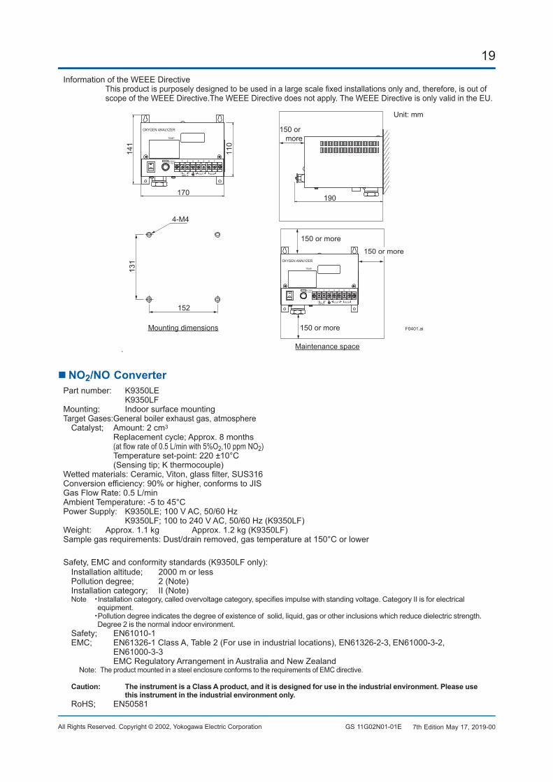
InformationoftheWEEEDirective Thisproductispurposelydesignedtobeusedinalargescalefixedinstallationsonlyand,therefore,isoutof
scopeoftheWEEEDirective.TheWEEEDirectivedoesnotapply.TheWEEEDirectiveisonlyvalidintheEU.
.
3 4 5 6 72
ALMAC
TEMP.
1 AC250VT3.15A
OXYGEN ANALYZER
INPUTOUT
SF EU
NL
170
110
141
190
131
152
4-M4
3 4 5 6 72
ALMAC
TEMP.
1 AC250VT3.15A
OXYGEN ANALYZER
INPUTOUT
SF EU
NL
F0401.ai
150 or more
150 or more
150 or more
150 or moreMounting dimensions
Maintenance space
Unit: mm
NO2/NOConverterPart number: K9350LE
K9350LFMounting: Indoor surface mountingTarget Gases:General boiler exhaust gas, atmosphereCatalyst; Amount:2cm3
Replacementcycle;Approx.8months (atflowrateof0.5L/minwith5%O2,10 ppm NO2) Temperatureset-point:220±10°C (Sensingtip;Kthermocouple)
Wettedmaterials:Ceramic,Viton,glassfilter,SUS316Conversionefficiency:90%orhigher,conformstoJISGasFlowRate:0.5L/minAmbientTemperature:-5to45°CPowerSupply: K9350LE;100VAC,50/60Hz K9350LF;100to240VAC,50/60Hz(K9350LF)Weight: Approx.1.1kg Approx.1.2kg(K9350LF)Samplegasrequirements:Dust/drainremoved,gastemperatureat150°Corlower
Safety,EMCandconformitystandards(K9350LFonly):Installationaltitude; 2000morlessPollutiondegree; 2(Note)Installationcategory; II(Note)Note ・Installationcategory,calledovervoltagecategory,specifiesimpulsewithstandingvoltage.CategoryIIisforelectrical
equipment. ・Pollutiondegreeindicatesthedegreeofexistenceofsolid,liquid,gasorotherinclusionswhichreducedielectricstrength.
Degree2isthenormalindoorenvironment.Safety; EN61010-1EMC; EN61326-1ClassA,Table2(Foruseinindustriallocations),EN61326-2-3,EN61000-3-2,
EN61000-3-3 EMCRegulatoryArrangementinAustraliaandNewZealand
Note: TheproductmountedinasteelenclosureconformstotherequirementsofEMCdirective.
Caution: TheinstrumentisaClassAproduct,anditisdesignedforuseintheindustrialenvironment.Pleaseusethisinstrumentintheindustrialenvironmentonly.
RoHS; EN50581
7th Edition May 17, 2019-00
20
All Rights Reserved. Copyright © 2002, Yokogawa Electric Corporation GS 11G02N01-01E
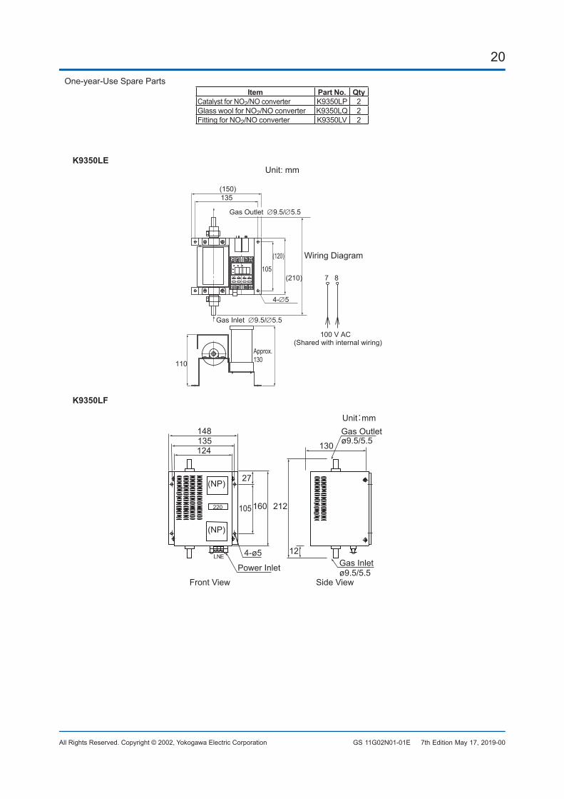
One-year-Use Spare PartsItem PartNo. Qty
Catalyst for NO2/NOconverter K9350LP 2GlasswoolforNO2/NOconverter K9350LQ 2Fitting for NO2/NOconverter K9350LV 2
K9350LEUnit: mm
7 8
100 V AC(Shared with internal wiring)
Wiring Diagram
Gas Inlet ∅9.5/∅5.5
4-∅5
135
(120)
105(210)
Approx.130110
(150)
Gas Outlet ∅9.5/∅5.5
K9350LF
Gas Inlet12
Power Inlet ø9.5/5.5
4-ø5
(NP)
(NP)
148135124
27
105 212160
Gas Outletø9.5/5.5
Unit:mm
130
Front View Side View
LNE
7th Edition May 17, 2019-00
21
All Rights Reserved. Copyright © 2002, Yokogawa Electric Corporation GS 11G02N01-01E
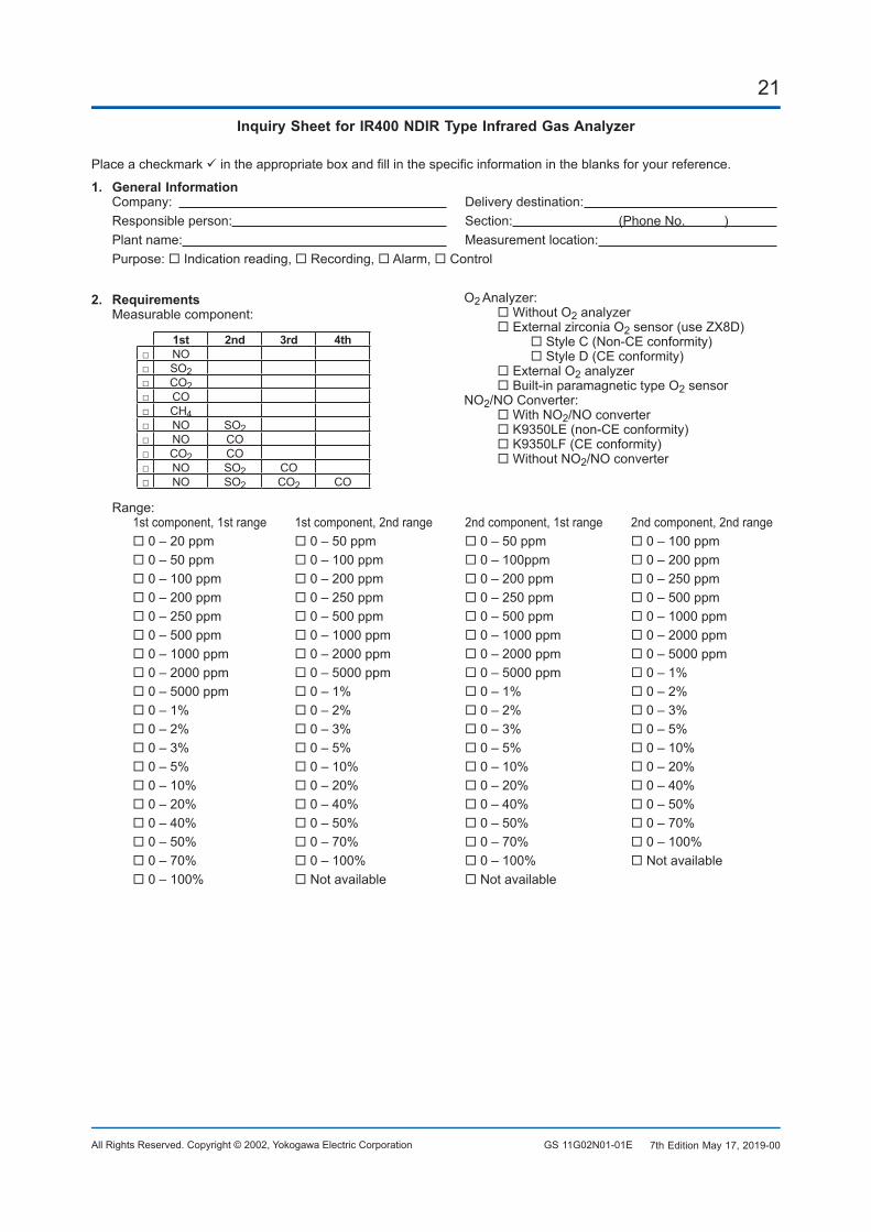
InquirySheetforIR400NDIRTypeInfraredGasAnalyzer
Place a checkmark intheappropriateboxandfillinthespecificinformationintheblanksforyourreference.
1. GeneralInformationCompany: Deliverydestination: Responsible person: Section: (PhoneNo. )Plant name: Measurement location: Purpose: Indication reading, Recording, Alarm, Control
2. RequirementsMeasurable component:
1st 2nd 3rd 4th□ NO□ SO2□ CO2□ CO□ CH4□ NO SO2□ NO CO□ CO2 CO□ NO SO2 CO□ NO SO2 CO2 CO
O2 Analyzer: WithoutO2 analyzer External zirconia O2sensor(useZX8D) StyleC(Non-CEconformity) StyleD(CEconformity) External O2 analyzer Built-in paramagnetic type O2 sensorNO2/NOConverter: WithNO2/NOconverter K9350LE(non-CEconformity) K9350LF(CEconformity) WithoutNO2/NOconverter
Range:1st component, 1st range 1st component, 2nd range 2nd component, 1st range 2nd component, 2nd range 0 – 20 ppm 0 – 50 ppm 0 – 50 ppm 0 – 100 ppm 0 – 50 ppm 0 – 100 ppm 0 – 100ppm 0 – 200 ppm 0 – 100 ppm 0 – 200 ppm 0 – 200 ppm 0 – 250 ppm 0 – 200 ppm 0 – 250 ppm 0 – 250 ppm 0 – 500 ppm 0 – 250 ppm 0 – 500 ppm 0 – 500 ppm 0 – 1000 ppm 0 – 500 ppm 0 – 1000 ppm 0 – 1000 ppm 0 – 2000 ppm 0 – 1000 ppm 0 – 2000 ppm 0 – 2000 ppm 0 – 5000 ppm 0 – 2000 ppm 0 – 5000 ppm 0 – 5000 ppm 0 – 1% 0 – 5000 ppm 0 – 1% 0 – 1% 0 – 2% 0 – 1% 0 – 2% 0 – 2% 0 – 3% 0 – 2% 0 – 3% 0 – 3% 0 – 5% 0 – 3% 0 – 5% 0 – 5% 0 – 10% 0 – 5% 0 – 10% 0 – 10% 0 – 20% 0 – 10% 0 – 20% 0 – 20% 0 – 40% 0 – 20% 0 – 40% 0 – 40% 0 – 50% 0 – 40% 0 – 50% 0 – 50% 0 – 70% 0 – 50% 0 – 70% 0 – 70% 0 – 100% 0 – 70% 0 – 100% 0 – 100% Notavailable 0 – 100% Notavailable Notavailable
7th Edition May 17, 2019-00
22
All Rights Reserved. Copyright © 2002, Yokogawa Electric Corporation GS 11G02N01-01E
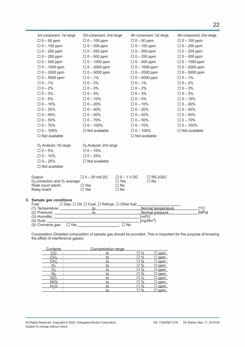
3rd component, 1st range 3rd component, 2nd range 4th component, 1st range 4th component, 2nd range 0 – 50 ppm 0 – 100 ppm 0 – 50 ppm 0 – 100 ppm 0 – 100 ppm 0 – 200 ppm 0 – 100 ppm 0 – 200 ppm 0 – 200 ppm 0 – 250 ppm 0 – 200 ppm 0 – 250 ppm 0 – 250 ppm 0 – 500 ppm 0 – 250 ppm 0 – 500 ppm 0 – 500 ppm 0 – 1000 ppm 0 – 500 ppm 0 – 1000 ppm 0 – 1000 ppm 0 – 2000 ppm 0 – 1000 ppm 0 – 2000 ppm 0 – 2000 ppm 0 – 5000 ppm 0 – 2000 ppm 0 – 5000 ppm 0 – 5000 ppm 0 – 1% 0 – 5000 ppm 0 – 1% 0 – 1% 0 – 2% 0 – 1% 0 – 2% 0 – 2% 0 – 3% 0 – 2% 0 – 3% 0 – 3% 0 – 5% 0 – 3% 0 – 5% 0 – 5% 0 – 10% 0 – 5% 0 – 10% 0 – 10% 0 – 20% 0 – 10% 0 – 20% 0 – 20% 0 – 40% 0 – 20% 0 – 40% 0 – 40% 0 – 50% 0 – 40% 0 – 50% 0 – 50% 0 – 70% 0 – 50% 0 – 70% 0 – 70% 0 – 100% 0 – 70% 0 – 100% 0 – 100% Notavailable 0 – 100% NotavailableNotavailable Notavailable
O2 Analyzer, 1st range O2 Analyzer, 2nd range 0 – 5% 0 – 10% 0 – 10% 0 – 25% 0 – 25% NotavailableNotavailable
Output: 4 – 20 mA DC 0 – 1 V DC RS-232CO2 correction and O2average: Yes NoPeak count alarm: Yes NoRelay board: Yes No
3. SamplegasconditionsFuel: Gas, Oil, Coal, Refuse, Other fuel (1)Temperature: to , Normal temperature [°C](2)Pressure: to , Normal pressure [MPa](3)Humidity: [vol%](4)Dust: [mg/Nm3](5)Corrosivegas: Yes No
Composition(Detailedcompositionofsamplegasshouldbeprovided.Thisisimportantforthepurposeofknowingtheeffectofinterferencegases)
Contents Concentration range CO : to % ppm CO2 : to % ppm CH4 : to % ppm H2 : to % ppm O2 : to % ppm N2 : to % ppm SO2 : to % ppm NOx : to % ppm H2O : to % ppm : to % ppm
Subjecttochangewithoutnotice.7th Edition May 17, 2019-00