Embed Size (px)
Citation preview
Ow n e r ’ s M a n u a l
*Quickie® IRIS *Zippie® IRIS*SE *Folding *With transit *Without transit Supplier: This manual must be given to the user of this wheelchair.
User: Before using this wheelchair read this entire manual and save for futurereference.
SECTION ENGLISH
IRIS
M a n u a l d e I n s t r u c c i o n e s
Distribuidor: Este manual debe ser entregado al pasajero de esta silla de ruedas. Pasajero: Antes de usar esta silla de ruedas, lea este manual en su totalidad y
guárdelo para futura referencia.Cada una de las sillas se envía con un manual de instrucciones en inglés. El manual en español ofrancés está disponible en formato PDF en nuestra página en Internet: www.SunriseMedical.com.Ingrese a la página del producto específico para descargar el manual, o comuníquese con elproveedor autorizado de Sunrise Medical.
M o d e d ’ e m p l o i
Fournisseur: Ce manuel doit être remis à l’utilisateur / utilisatrice de ce fauteuilroulant.
Utilisateur / Utilisatrice:Avant d’utiliser ce fauteuil roulant, lisez entièrement cemanuel et conservez le pour le consulter ultérieurement.
Chaque fauteuil est livré avec un manuel d’instructions en anglais. Les versions en espagnol et enfrancais sont à ançais est à votre disposition en format PDF sur le site:www.SunriseMedical.com. Veuillez vous rendre à la page de votre produit pour télécharger lemanuel dans la langue souhaitée, ou contactez un fournisseur agréé Sunrise Medical.
B e n u t z e r a n w e i s u n g e n
Fachhändler : Dieses Handbuch muss dem Benutzer des Rollstuhls ausge-händigt werden.
Benutzer : Vor dem Gebrauch des Rollstuhls lesen Sie bitte das gesamteHandbuch, und bewahren Sie es für zukünftigen Bedarf auf.
Zum Lieferumfang jedes Rollstuhls gehört ein Bedienungshandbuch in englischer Sprache. Dieseübersetzte Version des Handbuchs steht im PDF-Format auf unserer Website zur Verfügung:www.SunriseMedical.com. Gehen Sie bitte zu der betreffenden Produktsite für den Downloadder übersetzten Version oder wenden Sie sich an Ihren authorisierten Sunrise MedicalFachhändler.
M a n u a l e d ' u s o
Rivenditore : Il presente manuale va consegnato all'utente della carrozzina.Utente : Prima di usare la carrozzina, leggere il presente manuale per intero
e conservarlo per riferimento futuro.Ogni carrozzina è accompagnata da un manuale d’uso scritto in inglese. La versione tradotta èreperibile nel formato PDF sul nostro sito web: www.SunriseMedical.com. Visitare la pagina delprodotto specifico da scaricare, o contattare il fornitore Sunrise Medical autorizzato.
MK-100151 Rev. B 2
ENGLISH
I. INTRODUCTION
SUNRISE MEDICAL LISTENSThank you for choosing a Quickie/Zippie IRIS tilt in space wheelchair.We want to hear your questions or comments about this manual, thesafety and reliability of your chair, and the service you receive fromyour Sunrise supplier. Please feel free to write or call us at theaddress and telephone number below:
SUNRISE MEDICALCustomer Service Department2842 Business Park Avenue
Fresno, CA 93727(800) 333-4000
Be sure to return your warranty card, and let us know if you changeyour address. This will allow us to keep you up to date with informa-tion about safety, new products and options to increase your use andenjoyment of the wheelchair. If you lose your warranty card, call orwrite and we will gladly send you a new one.
FOR ANSWERS TO YOUR QUESTIONSYour authorized supplier knows your wheelchair best, and cananswer most of your questions about chair safety, use and mainte-nance. For future reference, fill in the following:
Supplier: ___________________________________________________________________________
Address: ___________________________________________________________________________
______________________________________________________________________________________
Telephone: ________________________________________________________________________
Serial #:_____________________________ Date/Purchased: ________________________
ADDITIONAL INFORMATION YOU SHOULD KNOWNo component of this chair was made with Natural Rubber Latex.
DISPOSAL AND RECYCLING INFORMATIONWhen this product reaches the end of its life, please take it to anapproved collection or recycling point designated by your local orstate government. This wheelchair is manufactured using a variety ofmaterials, Your product should not be disposed of as ordinaryhousehold waste. You should dispose of your wheelchair properly,according to local laws and regulations. Most materials that are usedin the construction of this product are fully recyclable. The seperatecollection and recycling of your product at the time of disposal willhelp conserve natural resources and ensure that it is dosposed in amanner that protects the environment.Ensure you are the legal owner of the product prior to arranging forthe product disposal in accordance with the above recommendations.

MK-100151 Rev. B3
ENGLISH
II. TABLE OF CONTENTS
I. INTRODUCTION ...........................................................................2 II. TABLE OF CONTENTS.................................................................3 III. YOUR CHAIR AND ITS PARTS..................................................4 IV. NOTICE– READ BEFORE USE ....................................................4 V. GENERAL WARNINGS .................................................................5 A.Weight limits ...............................................................................5 B. Intended Use ...............................................................................5 C. Attendants and Caregivers .....................................................5 D. Accessories.................................................................................5 E. Know your Chair .......................................................................5 F. Reduce the risk of an Accident...............................................5 G.Safety Checklist...........................................................................5 H.Changes and Adjustments ........................................................5 I. Environmental Conditions........................................................6 J. Terrain ..........................................................................................6 K. Street Use ...................................................................................6 L. Motor Vehicle Safety .................................................................6 M.When you need help .................................................................6 VI. SAFETY WARNINGS: FALLS & TIP-OVERS.............................7 A.Center of Balance.......................................................................7 B. Dressing or Changing Clothes ................................................7 C.Obstacles ......................................................................................7 D.Front Caster Lift.........................................................................7 E. Reaching or Leaning...................................................................7 F. Moving Backward........................................................................7 G.Escalators......................................................................................8 H. Ramps, Slopes, and Sidehills....................................................8 I. Transfer.........................................................................................8 J. Curbs and Single Steps...............................................................9 K.Climbing a Curb or Single Step...............................................9 L. Descending a Curb or Single Step .......................................10 M.Stairs............................................................................................10 N. Climbing Stairs.........................................................................10 O. Descending Stairs ...................................................................10 P. Tilt Use and Back Angle Adjustment (Mono Back).........10 VII. WARNINGS: COMPONENTS & OPTIONS..........................11 A.Anti-tip Tubes ...........................................................................11 B. Armrests.....................................................................................11 C.Push Handles .............................................................................11 D.Stroller Handle..........................................................................11 E. Cushions.....................................................................................11 F. Fasteners ....................................................................................11 G. Footrests ...................................................................................11 H Pneumatic Tires........................................................................11 I. Positioning Belts .......................................................................12 J. Quick Release Axle .................................................................12 K.Rear Axles..................................................................................12 L. Rear Wheel Locks ...................................................................12 M. Modified Seat Systems ...........................................................12 N. Tray for vent and battery .....................................................12 O. Accessory Hook .....................................................................12 VIII. USE AND MAINTENANCE ......................................................13 A. Introduction ............................................................................13 B. Critical Maintenance Tips.......................................................13 C.Maintenance Chart...................................................................13 D.Cleaning ......................................................................................13 E. Troubleshooting Chart ...........................................................13 F. To Mount and Remove Rear Wheels .................................14 G.Cushion Installation .................................................................14 H. Wheel Locks ............................................................................14
I. Hub Lock....................................................................................14 J. Anti-Tip Tubes-Rear.................................................................14 K. Dual-Post Armrests ................................................................15 L. Height-Adjustable Armrests ..................................................15 M.Adjustable Locking Flip-up Armrests ..................................15 N.Cantilever Armrests ................................................................16 O.Swing-away Hangers/Footrests.............................................16 P. Heavy-duty, Lift-off Footrests ...............................................16 Q.Articulating Legrest .................................................................16 R. Elevating Legrest.......................................................................17 S. Z-Finity Footrest System........................................................17 T. Z-Finity Swing-away Footrest ...............................................17 U.Tilt-in-Space Mechanism.........................................................18 V. Stroller Handle Extension ......................................................18 W.Reclining Back ..........................................................................18 X.Mono Back Stroller handle ....................................................19 Y. Folding the Mono back for Transport ................................19 Z. Folding/Unfolding frame.........................................................19 AA.Check-out................................................................................19 IX. DEALER SERVICE & ADJUSTMENT.........................................20 A.Dealer Service Introduction ..................................................20 B. Critical Maintenance Tips.......................................................20 C.Cleaning ......................................................................................20 D.Rear Axle ...................................................................................20 E. Hub Lock Adjustment.............................................................21 F. Wheel Locks .............................................................................21 G.Single-Post Armrest Receiver ...............................................21 H.Adjustable Locking Flip-up Armrests ..................................22 I. Cantilever Locking Flip-back armrests................................22 J. Swing-Away Height Adjustment ...........................................23 K.Heavy-Duty Lift-Off Footrest................................................23 L. Articulating Legrest..................................................................23 M.Elevating Legrest.......................................................................23 N.Contracture Footrest ............................................................24 O.Z-Finity Footrest System........................................................24 P. Tilt-in-space Mechanism .........................................................25 Q.Standard Backrest ....................................................................25 R. Mono Back .................................................................................26 S.Dynamic Mono Back.................................................................27 T. Dynamic Mono Back Elastomer Replacement ..................27 U.Ventilator Hanger Bracket ....................................................28 V. Fixed Stroller Handle ..............................................................28 W.Adjustable Stroller Handle (Mono Back) ..........................28 X.Caster/Fork Assembly .............................................................29 Y. Frame Depth .............................................................................29 Z.XLOCK™ Width Adjustment ..............................................30 AA.Frame Width...........................................................................30 BB.Seat Pan.....................................................................................31 CC.Carriage ...................................................................................31 DD.Attendant Wheel Lock Installation...................................33 EE.Footplate Adapter Bracket ...................................................34 FF.Lap Belt Instructions...............................................................35 GG.Check-Out..............................................................................35 X. SUNRISE LIMITED WARRANTY ..............................................36
ESPAÑOL .......................................................................................38 FRANÇAIS......................................................................................76 ITALIANO....................................................................................112 DEUTSCH.............................. ......................................................148
MK-100151 Rev. B 4
ENGLISH
III. YOUR CHAIR AND ITS PARTS
IV. NOTICE– READ BEFORE USE
A. CHOOSE THE RIGHT CHAIR & SAFETY OPTIONSSunrise provides a choice of many wheelchair styles to meet your needs.This product is intended for single person use only. Final selection of thetype of wheelchair, options and adjustments rests solely with you and yourhealth care professional. Choosing the best chair and set-up for your safetydepends on such things as:
1. Your disability, strength, balance and coordination.2. The types of hazards you must overcome in daily use (where you
live and work, and other places you are likely to use your chair).3. The need for options that will improve your positioning, safety and
comfort (such as anti-tip tubes, positioning belts, or special seatingsystems).
B. REVIEW THIS MANUAL OFTENBefore using this chair you, and each person who may assist you, shouldread this entire manual and make sure to follow all instructions. Reviewthe warnings often, until they are second nature to you.
C. WARNINGSThe word “WARNING” refers to a hazard or unsafe practice that maycause severe injury or death to you or to other persons. The “Warnings”are in Three main sections, as follows:
1. V– GENERAL WARNINGS Here you will find a safety checklist and a summary of risks youneed to be aware of before you ride this chair.
2. VI– SAFETY WARNINGS: FALLS & TIP-OVERSHere you will learnabout practices for the safe use of your chair,and how to avoid a fall or tip-over while you perform daily activi-ties in your chair.
3. VII– WARNINGS– COMPONENTS & OPTIONS Here you will learn about the components of your chair and optionsyou can select for safety. Consult your Premium Retailer and yourhealth care advisor to help you choose the best set-up and optionsfor safe use.
NOTE– Where they apply, you will also find “Warnings” in other sectionsof this manual. Heed all warnings in this section. If you fail to doso a fall, tip-over or loss of control may occur and cause severeinjury to the rider or others.
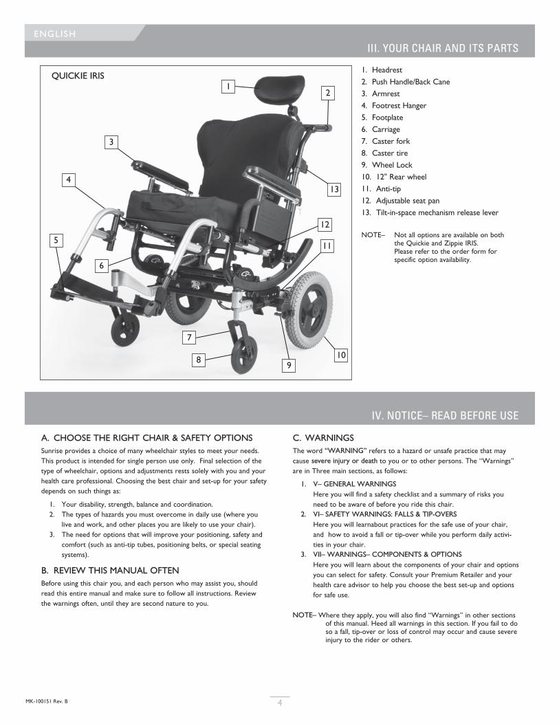
1. Headrest2. Push Handle/Back Cane3. Armrest4. Footrest Hanger5. Footplate6. Carriage7. Caster fork8. Caster tire9. Wheel Lock10. 12" Rear wheel11. Anti-tip12. Adjustable seat pan13. Tilt-in-space mechanism release lever
NOTE– Not all options are available on both the Quickie and Zippie IRIS. Please refer to the order form for specific option availability.
QUICKIE IRIS1
2
3
4
5
6
7
89
13
12
11
10
MK-100151 Rev. B5
ENGLISH
V. GENERAL WARNINGS
A. WEIGHT LIMITS
WARNINGNEVER exceed the weight limit specified by Sunrise Medical. The weightcapacity provided by your manufacturer is for the combined weight of arider and items carried using on-board storage. If you do exceed the weightlimit, damage to your chair, a fall, tip-over or loss of control may occur andcause severe injury to the rider or others.
Weight Capacities
Quickie IRIS - 250lbs/(113Kg).Zippie IRIS - 225lbs/(102kg).Quickie IRIS HD - 350lbs/(159kg).
B. INTENDED USE The Quickie and Zippie IRIS Series of wheelchair's intended use is to pro-vide mobility to persons limited to a sitting position.
WARNINGDO NOT use this device for purposes other than what is intended by themanufacturer
1. The wheelchiar is not designed for weight training and is unsafe foruse as a seat while weight training. Weight training from the wheel-chair substantially changes the stability of the chair and may causetipping.
2. DO NOT stand on the frame of the wheelchair.3. NEVER allow someone to stand on your chair or use it as a step
ladder.4. This chair is designed for a single rider only.5. Unauthorized modifications and use of parts or accessories not sup-
plied or approved by Sunrise Medical may change the chair struc-ture. This will void the warranty and may cause a safety hazard. Ifthe warning is ignored, damage to your chair, and the potentialsevere injury of the person using the chair for unintended purposescan occur.
C. ATTENDANTS AND CAREGIVERS
WARNINGBefore you assist a rider, be sure to read all warnings contained in thismanual, and follow all instructions that apply. Be aware that after consultinga healthcare advisor, you will need to learn safe and proven body mechan-ics to use and create assistive methods best suited to your abilities.
D. ACCESSORIES
WARNINGUnauthorized modifications or use of parts, or accessories not supplied orapproved by Sunrise Medical may change the chair structure. This will voidthe warranty and may cause a safety hazard.
Some problems that may occur, but are not limited to:
1. Incorrect Wheels and/or tires that put the rider at risk of a fall ortip-over.
2. Adding a component to the frame, changing the structural integrity ofthe chair.
3. Any modification or disassembly can potentially create an unsafe situ-ation where rider and/or attendant are put at risk.
E. KNOW YOUR CHAIR
WARNINGEvery wheelchair is different. Take the time to learn the feel of this chairbefore you begin riding. Start slowly, with easy, smooth strokes. If you areused to a different chair, you may use too much force and tip over. If youuse too much force, damage to your chair, a fall, tip-over or loss of controlmay occur and cause severe injury to the rider or others.
F. REDUCE THE RISK OF AN ACCIDENT
WARNING1. BEFORE riding, you should be trained in the safe use of this chair by
your health care advisor.2. Practice bending, reaching and transfers until you know the limit of
your ability. Have someone help you until you know what can causea fall or tip-over and how to avoid doing so.
3. Be aware that you must develop your own methods for safe usebest suited to your level of function and ability.
4. NEVER try a new maneuver on your own until you are sure youcan do it safely.
5. Get to know the areas where you plan to use your chair. Look forhazards and learn how to avoid them.
6. Sunrise recommends using anti-tip tubes in evey circumstance.
If you fail to heed these warnings, damage to your chair, a fall, tip-over orloss of control may occur and cause severe injury to the rider or others.
G. SAFETY CHECKLIST
WARNINGBefore Each Use Of Your Chair:1. Make sure the chair rolls easily and that all parts work smoothly.
Check for noise, vibration, or a change in ease of use. (They mayindicate low tire pressure, loose fasteners, or damage to yourchair).
2. Immediately repair any problem. Your authorized supplier can helpyou find and correct the problem.
3. Check to see that both quick-release rear axles are locked. Whenlocked, the axle button will “pop out” fully. If not locked, the wheelmay come off and cause you to fall.
4. If your chair has anti-tip tubes, lock them in place.
If you fail to heed these warnings, damage to your chair, a fall, tip-over orloss of control may occur and cause severe injury to the rider or others.
H. CHANGES & ADJUSTMENTS
WARNING1. See your healthcare advisor and have them adjust seating compo-
nents any time a change or adjustment needs to be made.2. Unauthorized modifications or use of parts not supplied or
approved by Sunrise may change the chair structure. This will voidthe warranty and may cause a safety hazard.
If you fail to heed these warnings, damage to your chair, a fall, tip-over orloss of control may occur and cause severe injury to the rider or others.
WARNINGIf your chair is NOT equipped with the Transit Option:1. NEVER let anyone sit in this chair while in a moving vehicle.
a. ALWAYS move the rider to an approved vehicle seat. b. ALWAYS secure the rider with proper motor vehicle restraints.
2. In an accident or sudden stop the rider may be thrown from thechair. Wheelchair seat belts will not prevent this, and further injurymay result from the belts or straps.
3. NEVER transport this chair in the front seat of a vehicle. It may shiftand interfere with the driver.
4. ALWAYS secure this chair so that it cannot roll or shift.5. Do not use any chair that has been involved in a motor vehicle acci-
dent. The frame and/or components may have been changed due tothe accident. Such items could be, but are not limited to: bent, loos-ened, and/or broken components that were subjected to an impact.
I. ENVIRONMENTAL CONDITIONS
WARNING1. Use extra care if you must ride your chair on a
wet or slick surface. If you are in doubt, ask forhelp.
2. Contact with water or excess moisture may cause your chair torust or corrode. Avoid all extreme weather situations if possible.a. Do not use your chair in a shower, pool or other body of
water. The chair tubing and parts are not water-tight and mayrust or corrode from the inside.
b. Avoid excess moisture (for example, do not leave your chair ina damp bathroom while taking a shower).
c. Dry your chair as soon as you can if it gets wet, or if you usewater to clean it.
J. TERRAIN
WARNING1. Based on ANSI/RESNA testing, Sunrise Medical recommends the
use of a caster wheel with a minimum diameter of 5”, if the wheel-chair will be overcoming obstacles up to 1/2” on a regular basis.
2. Your chair is designed for use on firm, even surfaces such as con-crete, asphalt, indoor flooring, and carpets.
3. Do not operate your chair in sand, loose soil, or over rocky terrain.4. If you use your chair on terrain that is rougher than described
above there is a danger that screws and bolts will loosen prema-turely, and that damage to wheels or axles could put the rider atrisk of a fall, tip-over, or loss of control.
If you fail to heed these warnings, damage to your chair, a fall, tip-over orloss of control may occur and cause severe injury to the rider or others.
K. STREET USE
WARNING1. This product is not intended for street use. 2. Avoid streets whenever possible.3. Obey and follow all legal pedestrian pathways, and laws that apply to
pedestrians.4. Be alert to the danger of motor vehicles in parking lots, or if you
must cross a road.
If you fail to heed these warnings, damage to your chair, a fall, tip-over orloss of control may occur and cause severe injury to the rider or others
L. MOTOR VEHICLE SAFETY
If possible and feasible, the rider should transfer to the Original EquipmentManufacturer vehicle seat and use the OEM vehicle restraint.
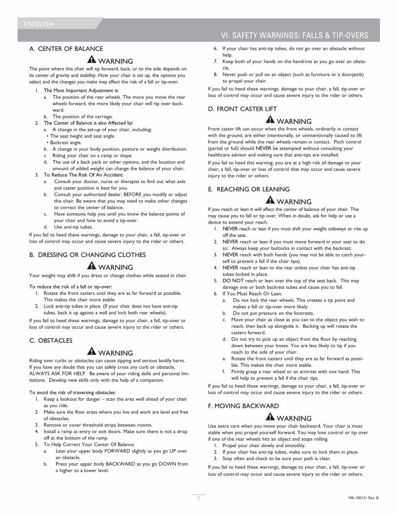
Sunrise Medical does provide a WC-19 Wheelchair Tie-Down andOccupant Restraint System, otherwise called a Transit Option. To Identifywhether your wheelchair has been manufactured with the Transit Optioninstalled, look for four points of securement. Two Front points (A), andtwo rear points (B). These points are recognized by the securement pointdecal which can be found on or near the securement points. If yourwheelchair is equipped with the Transit Option please review the TransitSecurement supplement that was provided with the wheelchair for addi-tional information and instructions. You can request a copy from yourauthorized supplier, or Sunrise medical at 1-800-333-4000 if you don’t haveit.
21
V. GENERAL WARNINGSENGLISH
6MK-100151 Rev. B
Front Transit hook
1 Rear Transit hook 2
A B
Look for this symbol on your wheelchair. It indicates wheel-chair securement points which conform to ANSI/RESNA (1998)V.1 - Section 19 and/or ANSI/RESNA (2012) V.4 WC-19. Formore Transit related information, see the “Transit SecurementSupplement” included with your chair.
M. WHEN YOU NEED HELP
WARNINGFor The Rider: Make sure that each person who helps you reads and fol-lows all warnings and instructions that apply.
For Attendants:1. Work with the rider’s doctor, nurse or therapist to learn safe meth-
ods best suited to your abilities and those of the rider.2. Tell the rider what you plan to do, and explain what you expect the
rider to do. This will put the rider at ease and reduce the risk of anaccident.
3. Make sure the chair has push handles. They provide secure pointsfor you to hold the rear of the chair to prevent a fall or tip-over.Check to make sure push handle grips will not rotate or slip off.
4. To prevent injury to your back, use good posture and proper bodymechanics. When you lift or support the rider or tilt the chair, bendyour knees slightly and keep your back as upright and straight as youcan.
5. Remind the rider to lean back when you tilt the chair backward.6. When you descend a curb or single step, slowly lower the chair in
one easy movement. Do not let the chair drop the last few inchesto the ground. This may damage the chair or injure the rider.
7. To avoid tipping, or getting hung up on objects, unlock and rotateanti-tip tubes up, and out of the way.
8. Whenever you aren’t attending the wheelchiar, ALWAYS use thewheel-lock to secure the rear wheels, and lock anti-tip tubes inplace if you must leave the rider alone, even for a moment. This willreduce the risk of a tip over or loss of control of the chair.
If you fail to heed these warnings, damage to your chair, a fall, tip-over orloss of control may occur and cause severe injury to the rider or others.
VI. SAFETY WARNINGS: FALLS & TIP-OVERS
6. If your chair has anti-tip tubes, do not go over an obstacle withouthelp.
7. Keep both of your hands on the handrims as you go over an obsta-cle.
8. Never push or pull on an object (such as furniture or a doorjamb)to propel your chair.
If you fail to heed these warnings, damage to your chair, a fall, tip-over orloss of control may occur and cause severe injury to the rider or others.
D. FRONT CASTER LIFT
WARNINGFront caster lift can occur when the front wheels, ordinarily in contactwith the ground, are either intentionally, or unintentionally caused to liftfrom the ground while the rear wheels remain in contact. Pitch control(partial or full) should NEVER be attempted without consulting yourhealthcare advisor and making sure that anti-tips are installed.
If you fail to heed this warning, you are at a high risk of damage to yourchair, a fall, tip-over or loss of control that may occur and cause severeinjury to the rider or others.
E. REACHING OR LEANING
WARNINGIf you reach or lean it will affect the center of balance of your chair. Thismay cause you to fall or tip over. When in doubt, ask for help or use adevice to extend your reach. 1. NEVER reach or lean if you must shift your weight sideways or rise up
off the seat.2. NEVER reach or lean if you must move forward in your seat to do
so. Always keep your buttocks in contact with the backrest.3. NEVER reach with both hands (you may not be able to catch your-
self to prevent a fall if the chair tips).4. NEVER reach or lean to the rear unless your chair has anti-tip
tubes locked in place.5. DO NOT reach or lean over the top of the seat back. This may
damage one or both backrest tubes and cause you to fall. 6. If You Must Reach Or Lean:
a. Do not lock the rear wheels. This creates a tip point andmakes a fall or tip-over more likely.
b. Do not put pressure on the footrests. c. Move your chair as close as you can to the object you wish to
reach, then back up alongside it. Backing up will rotate thecasters forward.
d. Do not try to pick up an object from the floor by reachingdown between your knees. You are less likely to tip if youreach to the side of your chair.
e. Rotate the front casters until they are as far forward as possi-ble. This makes the chair more stable.
f. Firmly grasp a rear wheel or an armrest with one hand. Thiswill help to prevent a fall if the chair tips.
If you fail to heed these warnings, damage to your chair, a fall, tip-over orloss of control may occur and cause severe injury to the rider or others.
F. MOVING BACKWARD
WARNINGUse extra care when you move your chair backward. Your chair is moststable when you propel yourself forward. You may lose control or tip overif one of the rear wheels hits an object and stops rolling. 1. Propel your chair slowly and smoothly.2. If your chair has anti-tip tubes, make sure to lock them in place.3. Stop often and check to be sure your path is clear.
If you fail to heed these warnings, damage to your chair, a fall, tip-over orloss of control may occur and cause severe injury to the rider or others.
A. CENTER OF BALANCE
WARNINGThe point where this chair will tip forward, back, or to the side depends onits center of gravity and stability. How your chair is set up, the options youselect and the changes you make may affect the risk of a fall or tip-over.
1. The Most Important Adjustment is:a. The position of the rear wheels. The more you move the rear
wheels forward, the more likely your chair will tip over back-ward.
b. The position of the carriage.2. The Center of Balance is also Affected by:
a. A change in the set-up of your chair, including: • The seat height and seat angle. • Backrest angle.b. A change in your body position, posture or weight distribution.c. Riding your chair on a ramp or slope. d. The use of a back pack or other options, and the location and
amount of added weight can change the balance of your chair,3. To Reduce The Risk Of An Accident:
a. Consult your doctor, nurse or therapist to find out what axleand caster position is best for you.
b. Consult your authorized dealer, BEFORE you modify or adjustthis chair. Be aware that you may need to make other changesto correct the center of balance.
c. Have someone help you until you know the balance points ofyour chair and how to avoid a tip-over.
d. Use anti-tip tubes.
If you fail to heed these warnings, damage to your chair, a fall, tip-over orloss of control may occur and cause severe injury to the rider or others.
B. DRESSING OR CHANGING CLOTHES
WARNINGYour weight may shift if you dress or change clothes while seated in chair.
To reduce the risk of a fall or tip-over:1. Rotate the front casters until they are as far forward as possible.
This makes the chair more stable. 2. Lock anti-tip tubes in place. (If your chair does not have anti-tip
tubes, back it up against a wall and lock both rear wheels).
If you fail to heed these warnings, damage to your chair, a fall, tip-over orloss of control may occur and cause severe injury to the rider or others.
C. OBSTACLES
WARNINGRiding over curbs or obstacles can cause tipping and serious bodily harm.If you have any doubt that you can safely cross any curb or obstacle,ALWAYS ASK FOR HELP. Be aware of your riding skills and personal lim-itations. Develop new skills only with the help of a companion.
To avoid the risk of traversing obstacles:1. Keep a lookout for danger – scan the area well ahead of your chair
as you ride.2. Make sure the floor areas where you live and work are level and free
of obstacles.3. Remove or cover threshold strips between rooms.4. Install a ramp at entry or exit doors. Make sure there is not a drop
off at the bottom of the ramp. 5. To Help Correct Your Center Of Balance:
a. Lean your upper body FORWARD slightly as you go UP overan obstacle.
b. Press your upper body BACKWARD as you go DOWN froma higher to a lower level.
ENGLISH
7 MK-100151 Rev. B
MK-100151 Rev. B 8
ENGLISH VI. SAFETY WARNINGS: FALLS & TIP-OVERS
G. ESCALATORS
WARNINGNEVER use this chair on an escalator, even with an attendant. If you do, a fall or tip-over is likely.
If you fail to heed these warnings, damage to your chair, a fall, tip-over or loss of control may occur andcause severe injury to the rider or others.
H. RAMPS, SLOPES & SIDEHILLS
WARNINGWhenever possible, avoid riding on a slope, which includes a ramp or sidehill. This will change the cen-ter of balance of your chair. Your chair is less stable and more difficult to manuever. when it is at anangle. When moving up a hill, anti-tip tubes may not prevent a fall or tip-over. 1. DO NOT use your chair on a slope steeper than 6%. 2. ALWAYS go as straight up and as straight down as you can. (Do not “cut the corner” on a slope
or ramp.) 3. DO NOT turn or change direction on a slope. 4. When you have to use a ramp, always stay in the CENTER of the ramp. Make sure ramp is wide
enough that you have no risk of going off the edge.5. DO NOT stop on a steep slope. If you stop, you may lose control of your chair. 6. NEVER use rear wheel locks to try to slow or stop your chair. This is likely to cause your chair
to veer out of control.7. ALWAYS be aware of:
a. Wet or slippery surfaces.b. A change in grade on a slope (or a lip, bump or depression). These may cause a fall or tip-
over.c. A drop-off at the bottom of a slope or ramp. A drop-off as small as 3/4 inch can stop a
front caster and cause the chair to tip forward.8. To Reduce The Risk Of A Fall Or Tip-Over:
a. Lean or press your body UPHILL. This will help adjust for the change in the center of bal-ance caused by the slope or sidehill.
b. Keep pressure on the handrims to control your speed on a down slope. If you go too fastyou may lose control.
c. ASK FOR HELP any time you are in doubt.9. Ramps At Home & Work– For your safety, ramps at home and work must meet all legal
requirements for your area:a. AVOID A DROP-OFF Make sure there is a section at the top or bottom to smooth out the transition.b. ALWAYS stay in the center of the ramp and control your speed.
If you fail to heed these warnings damage to your chair, a fall, tip-over or loss of control may occur andcan possibly cause severe injury to the rider or others.
I. TRANSFER
WARNINGIt is dangerous to transfer on your own. It requires good balance and agility. Be aware that there is apoint during every transfer when the wheelchair seat is not below you. To Avoid A Fall:
1. Work with your health care advisor to learn safe transfer methodsa. Learn how to position your body and how to support yourself during a transfer. b. Have someone help you until you know how to do a safe transfer on your own.
2. Lock the rear wheels before you transfer. 3. Be aware that the chair can still slide and/or tip. The wheel lock keeps the rear wheels from
rolling while you are perforrming the transfer.4. Make sure that the pneumatic tires are properly inflated. Low tire pressure may allow the rear
wheel locks to slip. (see table in Section G “Pneumatic Tires”5. Move your chair as close as you can to the seat you are transferring to.
6543
87
3
4
5
6
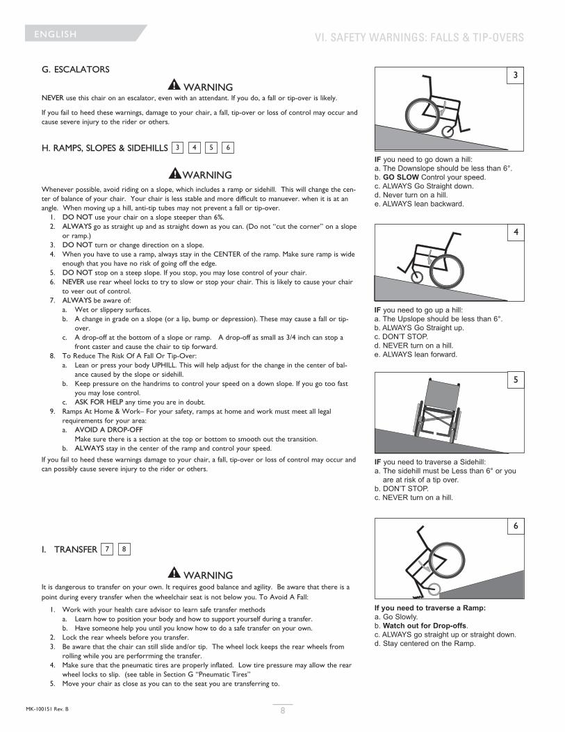
IF you need to go up a hill: a. The Upslope should be less than 6°.b. ALWAYS Go Straight up.c. DON’T STOP.d. NEVER turn on a hill.e. ALWAYS lean forward.
IF you need to traverse a Sidehill:a. The sidehill must be Less than 6° or you
are at risk of a tip over.b. DON’T STOP.c. NEVER turn on a hill.
If you need to traverse a Ramp:a. Go Slowly.b. Watch out for Drop-offs.c. ALWAYS go straight up or straight down.d. Stay centered on the Ramp.
IF you need to go down a hill: a. The Downslope should be less than 6°.b. GO SLOW Control your speed.c. ALWAYS Go Straight down.d. Never turn on a hill.e. ALWAYS lean backward.
MK-100151 Rev. B9
ENGLISH
J. CURBS & SINGLE STEPS
WARNINGBefore riding over curbs, or negotiating even a single step, ALWAYS ask for assistance first. Curbs and stepscan cause tipping and serious bodily harm. When in doubt as to our ability to avoid, or traverse any obsta-cle, ALWAYS ask for help. Be aware of your riding skills and personal limitations, develop new skills onlywith the help of a companion.
For Attendant: Each person who assists the rider with curbs and steps should read and follow all instruc-tions and warnings pertaining to attendants, and caregivers.
1. Do not try to climb a high curb or step (more than 4 inches high) UNLESS you have help. Doing so maycause your chair to exceed its balance point and tip over.
2. With the help of an attendant, go straight up and straight down a curb or step. If you climb ordescend at an angle, a fall or tip-over is likely.
3. Be aware that the impact of dropping down from a curb or step can damage your chair or loosen fas-teners.
If you fail to heed these warnings damage to your chair, a fall, tip-over or loss of control may occur and canpossibly cause severe injury to the rider or others.
K. CLIMBING A CURB OR SINGLE STEP
WARNINGFor Attendant: follow these steps to help the rider climb a curb or single step going BACKWARD:1. Stay behind the chair.2. Continue backward until the rear wheels contact the face of the curb or step. Lift and roll the rear
wheels to the top of the curb.3. Pull the chair backwards until the caster wheels have cleared the edge of the curb and return the chair
to it’s rolling position.
If you fail to heed these warnings damage to your chair, a fall, tip-over or loss of control may occur andcause severe injury to the rider or others.
9
9
VI. SAFETY WARNINGS: FALLS & TIP-OVERS
9
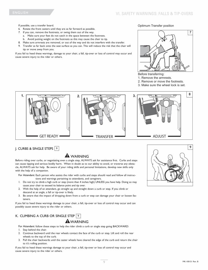
If possible, use a transfer board.6. Rotate the front casters until they are as far forward as possible. 7. If you can, remove the footrests, or swing them out of the way.
a. Make sure your feet do not catch in the space between the footrests.b. Avoid putting weight on the footrests as this may cause the chair to tip.
8. Make sure armrests are removed, or out of the way and do not interfere with the transfer.9. Transfer as far back onto the seat surface as you can. This will reduce the risk that the chair will
tip or move away from you.
If you fail to heed these warnings, damage to your chair, a fall, tip-over or loss of control may occur andcause severe injury to the rider or others.
7
Optimum Transfer position
Before transferring: 1. Remove the armrests. 2. Remove or move the footrests. 3. Make sure the wheel lock is set.
GET READY TRANSFER ADJUST
81. 2. 3.
L. DESCENDING A CURB OR SINGLE STEP
WARNINGFor Attendant:: Follow these steps to help a rider descend a curb or single step going FORWARD:1. Stay at the rear of the chair.2. Several feet before your reach the edge of the curb or step, tip the chair slightly and pull it backward.3. When the chair is at it’s balance point, carefully step forwards until the rear wheels reach the edge of
the curb or step. Then allow the rear wheels to slowly roll down onto the lower level.4. Push the chair forward until you are standing on the lower level.5. When the rear wheels are safely on the lower level, tilt the chair back to its balance point.
If you fail to heed these warnings damage to your chair, a fall, tip-over or loss of control may occur andcause severe injury to the rider or others.
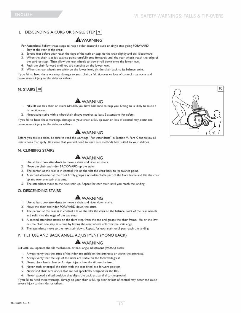
M. STAIRS
WARNING1. NEVER use this chair on stairs UNLESS you have someone to help you. Doing so is likely to cause a
fall or tip-over.2. Negotiating stairs with a wheelchair always requires at least 2 attendants for safety.
If you fail to heed these warnings, damage to your chair, a fall, tip-over or loss of control may occur andcause severe injury to the rider or others.
WARNINGBefore you assist a rider, be sure to read the warnings “For Attendants” in Section V, Part K and follow allinstructions that apply. Be aware that you will need to learn safe methods best suited to your abilities.
N. CLIMBING STAIRS
WARNING1. Use at least two attendants to move a chair and rider up stairs.2. Move the chair and rider BACKWARD up the stairs.3. The person at the rear is in control. He or she tilts the chair back to its balance point.4. A second attendant at the front firmly grasps a non-detachable part of the front frame and lifts the chair
up and over one stair at a time.5. The attendants move to the next stair up. Repeat for each stair, until you reach the landing.
O. DESCENDING STAIRS
WARNING1. Use at least two attendants to move a chair and rider down stairs.2. Move the chair and rider FORWARD down the stairs.3. The person at the rear is in control. He or she tilts the chair to the balance point of the rear wheels
and rolls it to the edge of the top step.4. A second attendant stands on the third step from the top and grasps the chair frame. He or she low-
ers the chair one step at a time by letting the rear wheels roll over the stair edge.5. The attendants move to the next stair down. Repeat for each stair, until you reach the landing.
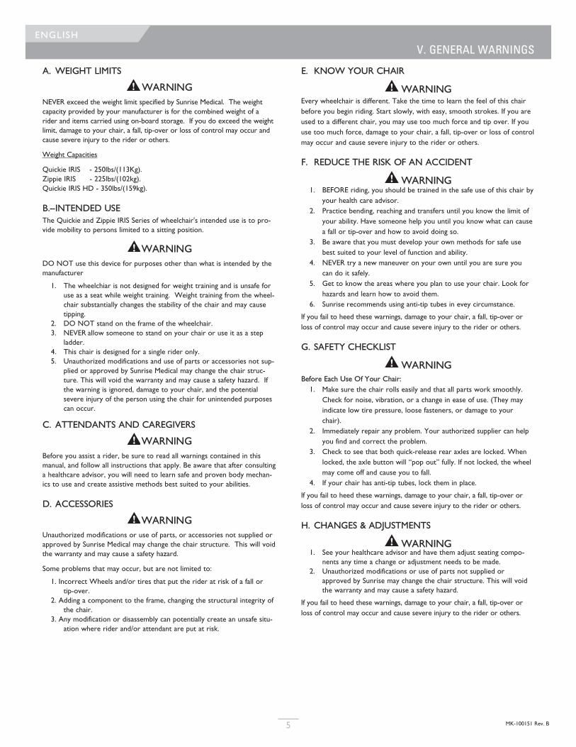
P. TILT USE AND BACK ANGLE ADJUSTMENT (MONO BACK)
WARNINGBEFORE you operate the tilt mechanism, or back angle adjustment (MONO back):
1. Always verify that the arms of the rider are stable on the armrests or within the armrests.2. Always verify that the legs of the rider are stable on the footrest/legrest. 3. Never place hands, feet or foreign objects into the tilt mechanism.4. Never push or propel the chair with the seat tilted in a forward position.5. Never add chair accessories that are not specifically designed for the IRIS.6. Never exceed a tilted position that aligns the backrest parallel to the ground.
If you fail to heed these warnings, damage to your chair, a fall, tip-over or loss of control may occur and causesevere injury to the rider or others.
9
10
VI. SAFETY WARNINGS: FALLS & TIP-OVERSENGLISH
10MK-100151 Rev. B
10
VII. WARNINGS, COMPONENTS & OPTIONS
F. FASTENERSWARNING
Many of the screws, bolts and nuts on this chair are special high-strengthfasteners. Use of improper fasteners may cause your chair to fail. 1. ONLY use fasteners provided by an authorized supplier (or ones of
the same type and strength, as indicated by the markings on theheads).
2. Over- or under-tightened fasteners may fail or cause damage tochair parts.
3. If bolts or screws become loose, tighten them as soon as you can.
If you fail to heed these warnings damage to your chair, a fall, tip-over orloss of control may occur and cause severe injury to the rider or others.
G. FOOTRESTS
WARNING1. At the lowest point, footrests should be AT LEAST 2 inches off the
ground. If set too LOW, they may “hang up” on obstacles you canexpect to find in normal use. This may cause the chair to stop sud-denly and tip forward.
2. To Avoid A Trip Or Fall When You Transfer:a. Make sure your feet do not “hang up” or get caught in the
space between the footrests.b. Avoid putting weight on the footrests, as the chair may tip forward.c. Footrests should be swung out of the way or removed whenever
entering or exiting the wheelchair.3. NEVER lift this chair by the footrests. Footrests detach and will not
bear the weight of this chair. Lift this chair only by non-detachableparts of the main frame.
If you fail to heed these warnings damage to your chair, a fall, tip-over orloss of control may occur and cause severe injury to the rider or others.
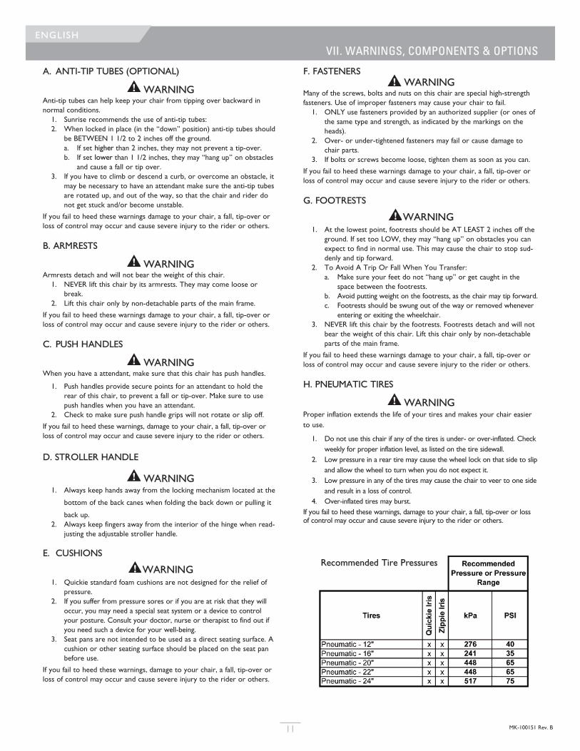
H. PNEUMATIC TIRES
WARNINGProper inflation extends the life of your tires and makes your chair easierto use.
1. Do not use this chair if any of the tires is under- or over-inflated. Checkweekly for proper inflation level, as listed on the tire sidewall.
2. Low pressure in a rear tire may cause the wheel lock on that side to slipand allow the wheel to turn when you do not expect it.
3. Low pressure in any of the tires may cause the chair to veer to one sideand result in a loss of control.
4. Over-inflated tires may burst.If you fail to heed these warnings, damage to your chair, a fall, tip-over or lossof control may occur and cause severe injury to the rider or others.
A. ANTI-TIP TUBES (OPTIONAL)
WARNINGAnti-tip tubes can help keep your chair from tipping over backward in normal conditions.1. Sunrise recommends the use of anti-tip tubes:2. When locked in place (in the “down” position) anti-tip tubes should
be BETWEEN 1 1/2 to 2 inches off the ground.a. If set higher than 2 inches, they may not prevent a tip-over.b. If set lower than 1 1/2 inches, they may “hang up” on obstacles
and cause a fall or tip over.3. If you have to climb or descend a curb, or overcome an obstacle, it
may be necessary to have an attendant make sure the anti-tip tubesare rotated up, and out of the way, so that the chair and rider donot get stuck and/or become unstable.
If you fail to heed these warnings damage to your chair, a fall, tip-over orloss of control may occur and cause severe injury to the rider or others.
B. ARMRESTS
WARNINGArmrests detach and will not bear the weight of this chair.1. NEVER lift this chair by its armrests. They may come loose or
break.2. Lift this chair only by non-detachable parts of the main frame.
If you fail to heed these warnings damage to your chair, a fall, tip-over orloss of control may occur and cause severe injury to the rider or others.
C. PUSH HANDLES
WARNINGWhen you have a attendant, make sure that this chair has push handles.
1. Push handles provide secure points for an attendant to hold therear of this chair, to prevent a fall or tip-over. Make sure to usepush handles when you have an attendant.
2. Check to make sure push handle grips will not rotate or slip off.
If you fail to heed these warnings, damage to your chair, a fall, tip-over orloss of control may occur and cause severe injury to the rider or others.
D. STROLLER HANDLE
WARNING1. Always keep hands away from the locking mechanism located at the
bottom of the back canes when folding the back down or pulling it
back up.2. Always keep fingers away from the interior of the hinge when read-
justing the adjustable stroller handle.
E. CUSHIONS
WARNING1. Quickie standard foam cushions are not designed for the relief of
pressure.2. If you suffer from pressure sores or if you are at risk that they will
occur, you may need a special seat system or a device to controlyour posture. Consult your doctor, nurse or therapist to find out ifyou need such a device for your well-being.
3. Seat pans are not intended to be used as a direct seating surface. Acushion or other seating surface should be placed on the seat panbefore use.
If you fail to heed these warnings, damage to your chair, a fall, tip-over orloss of control may occur and cause severe injury to the rider or others.
ENGLISH
11 MK-100151 Rev. B
Recommended Tire Pressures
I. POSITIONING BELTS (OPTIONAL)
WARNINGUse positioning belts ONLY to help support the rider’s posture. Improperuse of these belts may cause severe injury to or death to the rider.1. Make sure the rider does not slide down in the wheelchair seat. If
this occurs, the rider may suffer chest compression or suffocate dueto pressure from the belts.
2. The belts must be snug, but must not be so tight that they interferewith breathing. You should be able to slide your open hand, flat,between the belt and the rider.
3. A pelvic wedge or a similar device can help keep the rider from slid-ing down in the seat. Consult with the rider’s doctor, nurse ortherapist to find out if the rider needs such a device.
4. Use positioning belts only with a rider who can cooperate. Makesure the rider can easily remove the belts in an emergency.
5. NEVER Use Positioning Belts:a. As a patient restraint. A restraint requires a doctor’s order.b. On a rider who is comatose or agitated.c. As a motor vehicle restraint. In an accident or sudden stop the
rider may be thrown from the chair. Wheelchair seat belts willnot prevent this, and further injury may result from the belts orstraps.
If you fail to heed these warnings damage to your chair, a fall, tip-over orloss of control may occur and cause severe injury to the rider or others.
J. QUICK-RELEASE AXLES
WARNING1. Do not use this chair UNLESS you are sure that both quick-release
rear axles are locked. 2. An axle is not locked until the quick-release button pops out fully. If
the axle is not inserted fully, the wheel may come off during use,endangering the rider.
3. Quick-release axles should be periodically cleaned and inspected forfunction, and signs of wear or bending. Replace as necessary.
If you fail to heed these warnings, damage to your chair, a fall, tip-over orloss of control may occur and cause severe injury to the rider or others.
K REAR AXLES
WARNINGA change in set-up of the rear wheels will affect the center of balanceof your chair.
1. The farther you move the rear axles FORWARD, the more likely itis that your chair will tip over backward.
2. Consult your doctor, nurse or therapist to find the best rear axleset-up for your chair. Do not change the set-up UNLESS you aresure you are not at risk to tip over.
3. Adjust the rear wheel locks after you make any change to the rearaxles. a. If you fail to do so, the locks may not work.b. Make sure lock arms embed in tires at least 1/8 inch when
locked.If you fail to heed these warnings, damage to your chair, a fall, tip-over orloss of control may occur and cause severe injury to the rider or others.
L. REAR WHEEL LOCKS
WARNINGRear wheel locks are NOT designed to slow or stop a moving wheelchair.Use them only to keep the rear wheels from rolling when your chair is at acomplete stop. 1. NEVER use rear wheel locks to try to slow or stop your chair when
it is moving. Doing so may cause a fall or tip-over 2. To keep the rear wheels from rolling, always set both rear wheel
locks when you transfer to or from your chair.3. Low pressure in a rear tire may cause the wheel lock on that side
to slip and may allow the wheel to turn when you do not expect it.4. Make sure lock arms embed in tires at least 1/8 inch when locked. If
you fail to do so, the locks may not work.
If you fail to heed these warnings damage to your chair, a fall, tip-over orloss of control may occur and cause severe injury to the rider or others.
M. MODIFIED SEAT SYSTEMS
WARNINGUse of a seat system not approved by Sunrise may alter the center of bal-ance of this chair. This may cause the chair to tip over. 1. Do not change the seat system of your chair UNLESS you consult
your authorized supplier first.2. Use of a seating system not provided by Sunrise is prohibited for
transit use.
If you fail to heed these warnings damage to your chair, a fall, tip-over orloss of control may occur and cause severe injury to the rider or others.
N. TRAY FOR VENT AND BATTERY
NOTE– Vent tray only available on the Quickie IRIS.
NOTE– This option is only compatible with wheelchairs having a mini-mum floor-to-seat height of 15" (38 cm).
NOTE– The battery tray components are not compatible with theAttendant Wheel Lock option or foot release tilt.
WARNINGNever use this wheelchair as a seat in a motor vehicle unless all com-ponents are removed from the battery tray, and properly securedseparately in the vehicle.
WARNINGAlways contact Technical Service before installing or removing thebattery tray components to obtain the correct assembly locations ofthe strut tubes, roller carriage assembly and caster brackets.
WARNINGThe combined weight of the user plus the ventilator, battery and traycomponents should not exceed 225 lbs (102 kg) on the Zippie IRIS,250 lbs (114 kg) on the Quickie IRIS, and 350 lbs (159 kg) on theheavy duty option.
O. ACCESSORY HOOK
WARNINGThe weight limit for the accessory hook is 10lbs (total) for all items
If you fail to heed these warnings damage to your chair, a fall, tip-over orloss of control may occur and cause severe injury to the rider or others.
VII. WARNINGS: COMPONENTS & OPTIONSENGLISH
12MK-100151 Rev. B
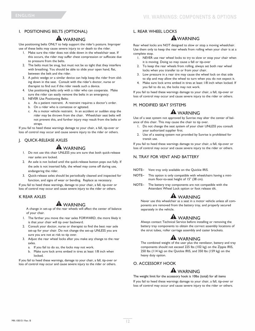
R R R R Make sure tire pressure is cor-
rect and equal in both rear tiresand front caster tires, if pneu-matic.
R R R R Make sure all nuts and boltsare snug.
R R Make sure all spokes and nipples
are tight on radial spoke wheels.
R Use Tri-Flow Lubricant
(Teflon™-based) between allmodular frame connections andparts.
R R R R Check for proper caster plate
adjustment. See instructions forcaster plate adjustment.
R R R Make sure both front casters
touch the ground simultaneous-ly. If they do not, add the prop-er spacers between the bottombearing of the caster plate andfork stem nut until they do.Make sure you check for thisproblem on a flat surface.
R Consult with an authorized sup-
plier to adjust CG/CR forward
R Consult with an authorized sup-
plier to adjust
ENGLISH
13 MK-100151 Rev. B
VIII. USE AND MAINTENANCE
WARNING
The owner and/or Caregiver for the use of this product, is responsible for
making sure that it has been setup and adjusted by a trained service pro-
fessional under the advice of a healthcare advisor. The chair may require
periodic maintenance or certain in-use adjustments that may be performed
by the owner or caregiver.
A. INTRODUCTION1. Proper maintenance will improve performance and extend the use-
ful life of your chair.2. Clean your chair regularly. This will help you find loose or worn
parts and make your chair easier to use. You will need a milddetergent solution and plenty of cleaning rags.
3. If discovered, repair or replace loose, worn, bent or damaged partsbefore using the chair.
4. To protect your investment, have all major maintenance and repairwork done by your authorized dealer.
5. Inspect and maintain this chair strictly per the maintenance chart.6. If you detect a problem, make sure to order parts, or have service,
and repair work done at your authorized dealer before use.7. At least once per year, have a complete inspection, safety check,
and service of your chair made by an authorized dealer.
B. CRITICAL MAINTENANCE TIPS
1. Tire Air Pressure:Check air pressure in pneumatic tires at least ONCE PER WEEK. Thewheel locks will not grip properly if you fail to maintain the air pressureshown on tire sidewall.
2. Axles & Axle Sleeves:When checking axles and axle sleeves every six months, make sure theyare clean and tight. Loose sleeves will damage the axle plate and will affect performance.
D. CLEANING
1. Paint Finisha. Clean the painted surfaces with mild soap or detergent at least once
a month.b. Protect the paint with a coat of non-abrasive auto wax every three
months.
2. Axles and Moving Partsa. Clean around axles and moving parts WEEKLY with a slightly damp
(not wet) cloth.b. Wipe off or blow away any fluff, dust or dirt on axles or moving
parts.
3. Upholsterya. Hand-wash (machine washing may damage fabric).b. Drip-dry only. DO NOT machine dry as heat will damage fabric.
4. Basic Maintenance Materials available at local storea. Tire Pumpb. Clean rags or cotten cloth.c. Teflon-based Lubricantd. Mild Detergent.
NOTE– You do not need to grease or oil the chair.
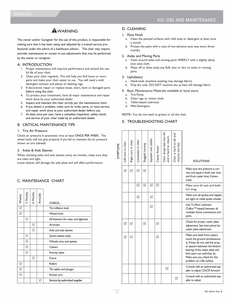
C. MAINTENANCE CHART
E. TROUBLESHOOTING CHART
Weekly
3 Months
6 Months
Annually
R Tire inflation level
R Wheel locks
R All fasteners for wear and tightness
R Armrests
R Axle and axle sleeves
R Quick-release axles
R Wheels, tires and spokes
R Casters
R Anti-tip tubes
R Frame
R Rollers
R Tilt cables and plunger
R Rocker arm
R Service by authorized supplier
CHECK...
SOLUTIONS
SYMPTOMS
Left turn in chair
Right turn in chair
Looseness in chair
Sluggish turning
Squeaks and rattles
Caster flutter
Chair drops fast into tilt
and is hard to return.
Chair is hard to tilt and
returns too fast.
MK-100151 Rev. B 14
ENGLISH
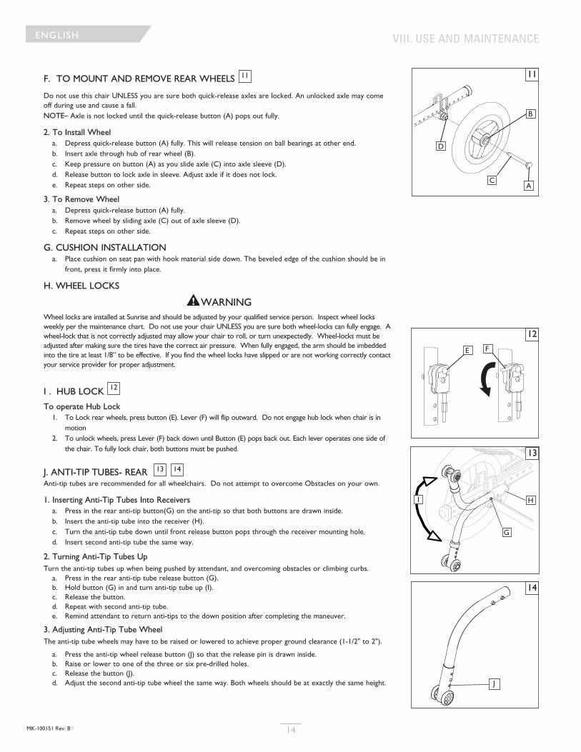
F. TO MOUNT AND REMOVE REAR WHEELS
Do not use this chair UNLESS you are sure both quick-release axles are locked. An unlocked axle may comeoff during use and cause a fall.NOTE– Axle is not locked until the quick-release button (A) pops out fully.
2. To Install Wheela. Depress quick-release button (A) fully. This will release tension on ball bearings at other end.b. Insert axle through hub of rear wheel (B).c. Keep pressure on button (A) as you slide axle (C) into axle sleeve (D).d. Release button to lock axle in sleeve. Adjust axle if it does not lock. e. Repeat steps on other side.
3. To Remove Wheela. Depress quick-release button (A) fully.b. Remove wheel by sliding axle (C) out of axle sleeve (D).c. Repeat steps on other side.
G. CUSHION INSTALLATIONa. Place cushion on seat pan with hook material side down. The beveled edge of the cushion should be in
front, press it firmly into place.
H. WHEEL LOCKS
WARNINGWheel locks are installed at Sunrise and should be adjusted by your qualified service person. Inspect wheel locksweekly per the maintenance chart. Do not use your chair UNLESS you are sure both wheel-locks can fully engage. Awheel-lock that is not correctly adjusted may allow your chair to roll, or turn unexpectedly. Wheel-locks must beadjusted after making sure the tires have the correct air pressure. When fully engaged, the arm should be imbeddedinto the tire at least 1/8” to be effective. If you find the wheel locks have slipped or are not working correctly contactyour service provider for proper adjustment.
I . HUB LOCK
To operate Hub Lock1. To Lock rear wheels, press button (E). Lever (F) will flip outward. Do not engage hub lock when chair is in
motion2. To unlock wheels, press Lever (F) back down until Button (E) pops back out. Each lever operates one side of
the chair. To fully lock chair, both buttons must be pushed.
J. ANTI-TIP TUBES- REAR Anti-tip tubes are recommended for all wheelchairs. Do not attempt to overcome Obstacles on your own.
1. Inserting Anti-Tip Tubes Into Receiversa. Press in the rear anti-tip button(G) on the anti-tip so that both buttons are drawn inside.b. Insert the anti-tip tube into the receiver (H).c. Turn the anti-tip tube down until front release button pops through the receiver mounting hole.d. Insert second anti-tip tube the same way.
2. Turning Anti-Tip Tubes UpTurn the anti-tip tubes up when being pushed by attendant, and overcoming obstacles or climbing curbs.a. Press in the rear anti-tip tube release button (G).b. Hold button (G) in and turn anti-tip tube up (I).c. Release the button.d. Repeat with second anti-tip tube.e. Remind attendant to return anti-tips to the down position after completing the maneuver.
3. Adjusting Anti-Tip Tube WheelThe anti-tip tube wheels may have to be raised or lowered to achieve proper ground clearance (1-1/2" to 2").
a. Press the anti-tip wheel release button (J) so that the release pin is drawn inside.b. Raise or lower to one of the three or six pre-drilled holes.c. Release the button (J).d. Adjust the second anti-tip tube wheel the same way. Both wheels should be at exactly the same height.
11
12
1413
13
A
B
C
D
E F
I
G
H
11
12
14
J
VIII. USE AND MAINTENANCE
MK-100151 Rev. B15
ENGLISH
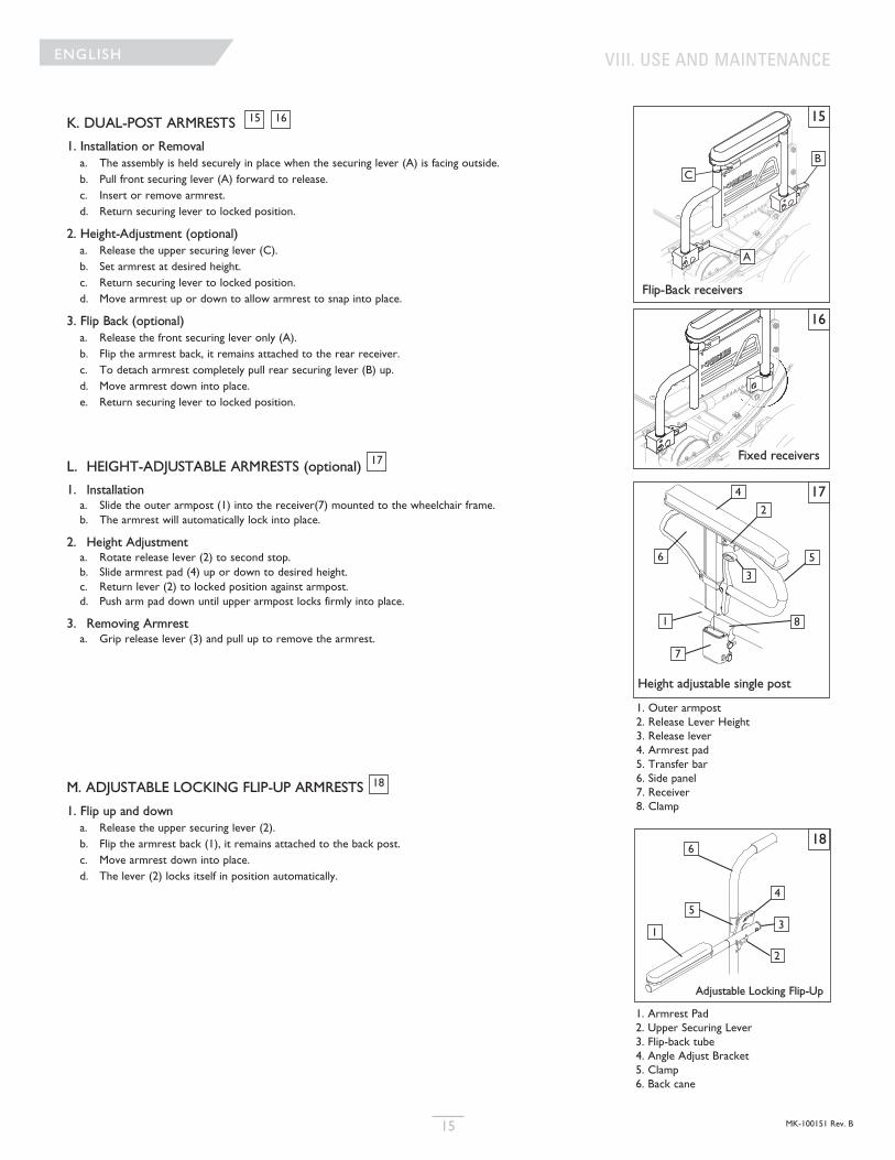
K. DUAL-POST ARMRESTS
1. Installation or Removala. The assembly is held securely in place when the securing lever (A) is facing outside.b. Pull front securing lever (A) forward to release.c. Insert or remove armrest.d. Return securing lever to locked position.
2. Height-Adjustment (optional)a. Release the upper securing lever (C).b. Set armrest at desired height.c. Return securing lever to locked position.d. Move armrest up or down to allow armrest to snap into place.
3. Flip Back (optional)a. Release the front securing lever only (A).b. Flip the armrest back, it remains attached to the rear receiver.c. To detach armrest completely pull rear securing lever (B) up.d. Move armrest down into place.e. Return securing lever to locked position.
L. HEIGHT-ADJUSTABLE ARMRESTS (optional)
1. Installationa. Slide the outer armpost (1) into the receiver(7) mounted to the wheelchair frame.b. The armrest will automatically lock into place.
2. Height Adjustmenta. Rotate release lever (2) to second stop.b. Slide armrest pad (4) up or down to desired height.c. Return lever (2) to locked position against armpost.d. Push arm pad down until upper armpost locks firmly into place.
3. Removing Armresta. Grip release lever (3) and pull up to remove the armrest.
M. ADJUSTABLE LOCKING FLIP-UP ARMRESTS
1. Flip up and downa. Release the upper securing lever (2).b. Flip the armrest back (1), it remains attached to the back post.c. Move armrest down into place.d. The lever (2) locks itself in position automatically.
1615
17
18
Flip-Back receivers
Fixed receivers
1. Armrest Pad2. Upper Securing Lever3. Flip-back tube4. Angle Adjust Bracket5. Clamp6. Back cane
Adjustable Locking Flip-Up
Height adjustable single post
15
16
17
18
A
BC
1
2
3
4
56
7
1
5
6
2
3
4
8
1. Outer armpost2. Release Lever Height3. Release lever4. Armrest pad5. Transfer bar6. Side panel7. Receiver8. Clamp
VIII. USE AND MAINTENANCE
MK-100151 Rev. B 16
ENGLISH
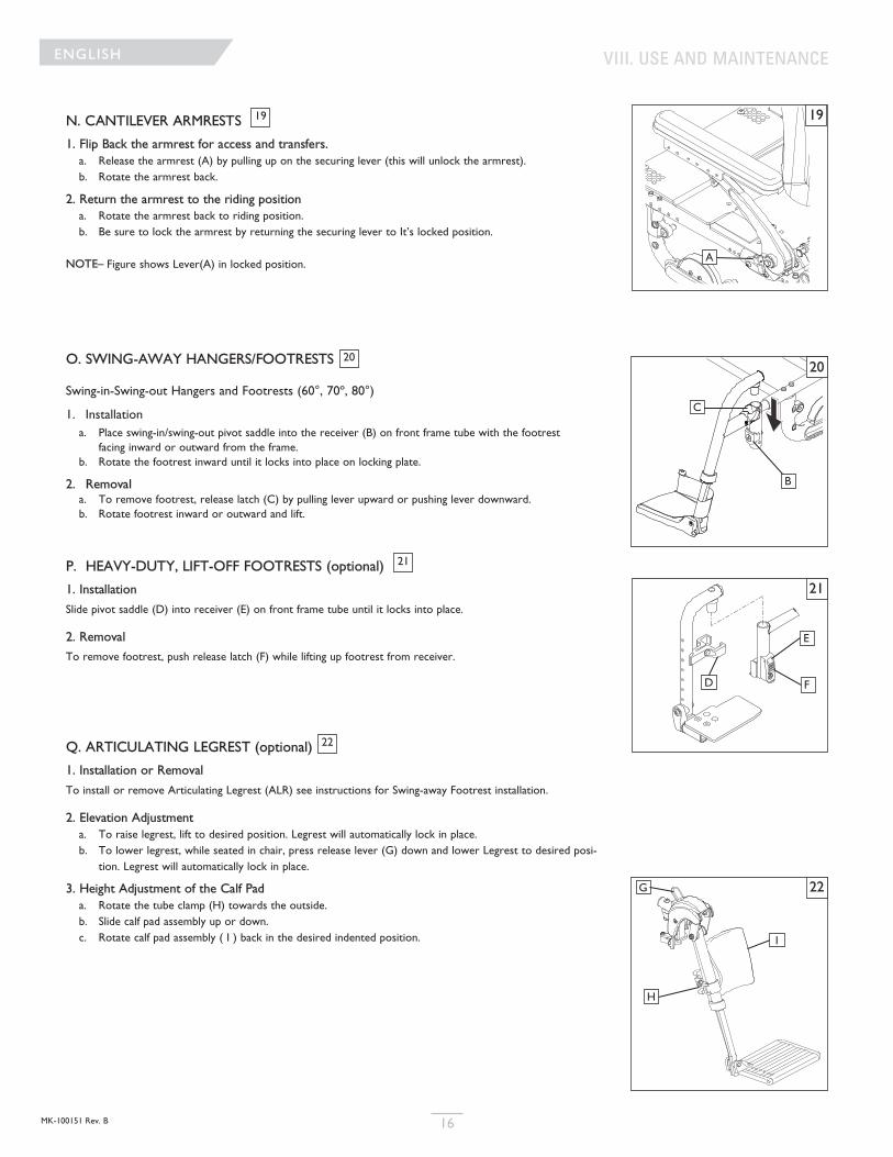
N. CANTILEVER ARMRESTS
1. Flip Back the armrest for access and transfers. a. Release the armrest (A) by pulling up on the securing lever (this will unlock the armrest).b. Rotate the armrest back.
2. Return the armrest to the riding positiona. Rotate the armrest back to riding position.b. Be sure to lock the armrest by returning the securing lever to It’s locked position.
NOTE– Figure shows Lever(A) in locked position.
O. SWING-AWAY HANGERS/FOOTRESTS
Swing-in-Swing-out Hangers and Footrests (60°, 70º, 80°)
1. Installation a. Place swing-in/swing-out pivot saddle into the receiver (B) on front frame tube with the footrest
facing inward or outward from the frame. b. Rotate the footrest inward until it locks into place on locking plate.
2. Removala. To remove footrest, release latch (C) by pulling lever upward or pushing lever downward.b. Rotate footrest inward or outward and lift.
P. HEAVY-DUTY, LIFT-OFF FOOTRESTS (optional)
1. Installation
Slide pivot saddle (D) into receiver (E) on front frame tube until it locks into place.
2. Removal
To remove footrest, push release latch (F) while lifting up footrest from receiver.
Q. ARTICULATING LEGREST (optional)
1. Installation or Removal
To install or remove Articulating Legrest (ALR) see instructions for Swing-away Footrest installation.
2. Elevation Adjustment a. To raise legrest, lift to desired position. Legrest will automatically lock in place.b. To lower legrest, while seated in chair, press release lever (G) down and lower Legrest to desired posi-
tion. Legrest will automatically lock in place.
3. Height Adjustment of the Calf Pad a. Rotate the tube clamp (H) towards the outside. b. Slide calf pad assembly up or down.c. Rotate calf pad assembly ( I ) back in the desired indented position.
19
20
21
22
20
21
22
D
E
F
G
H
I
B
C
19
A
VIII. USE AND MAINTENANCE
MK-100151 Rev. B17
ENGLISH
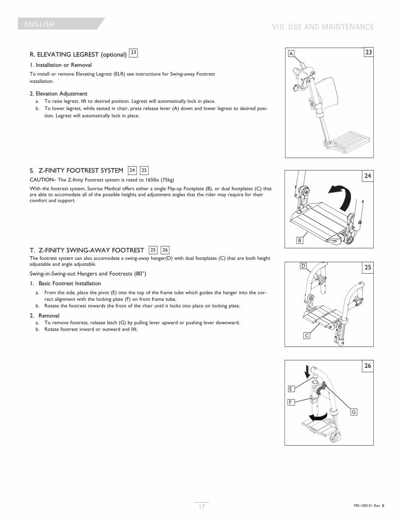
R. ELEVATING LEGREST (optional)
1. Installation or Removal
To install or remove Elevating Legrest (ELR) see instructions for Swing-away Footrest installation.
2. Elevation Adjustment a. To raise legrest, lift to desired position. Legrest will automatically lock in place.b. To lower legrest, while seated in chair, press release lever (A) down and lower legrest to desired posi-
tion. Legrest will automatically lock in place.
S. Z-FINITY FOOTREST SYSTEM CAUTION– The Z-finity Footrest system is rated to 165lbs (75kg)
With the footrest system, Sunrise Medical offers either a single Flip-up Footplate (B), or dual footplates (C) thatare able to accomodate all of the possible heights and adjustment angles that the rider may require for theircomfort and support.
T. Z-FINITY SWING-AWAY FOOTREST The footrest system can also accomodate a swing-away hanger(D) with dual footplates (C) that are both heightadjustable and angle adjustable.
Swing-in-Swing-out Hangers and Footrests (80°)
1. Basic Footrest Installation
a. From the side, place the pivot (E) into the top of the frame tube which guides the hanger into the cor-rect alignment with the locking plate (F) on front frame tube.
b. Rotate the footrest towards the front of the chair until it locks into place on locking plate.
2. Removala. To remove footrest, release latch (G) by pulling lever upward or pushing lever downward.b. Rotate footrest inward or outward and lift.
23
24 25
25 26
23A
VIII. USE AND MAINTENANCE
25D
24
B
C
26
E
G
F
MK-100151 Rev. B 18
ENGLISH
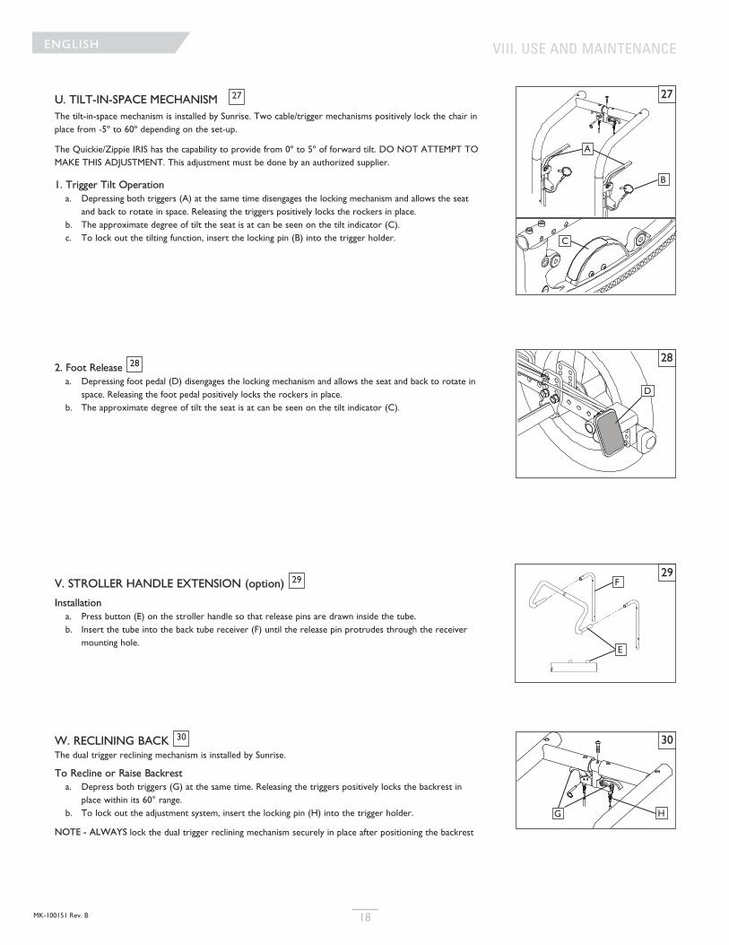
U. TILT-IN-SPACE MECHANISM The tilt-in-space mechanism is installed by Sunrise. Two cable/trigger mechanisms positively lock the chair inplace from -5º to 60º depending on the set-up.
The Quickie/Zippie IRIS has the capability to provide from 0º to 5º of forward tilt. DO NOT ATTEMPT TOMAKE THIS ADJUSTMENT. This adjustment must be done by an authorized supplier.
1. Trigger Tilt Operationa. Depressing both triggers (A) at the same time disengages the locking mechanism and allows the seat
and back to rotate in space. Releasing the triggers positively locks the rockers in place.b. The approximate degree of tilt the seat is at can be seen on the tilt indicator (C).c. To lock out the tilting function, insert the locking pin (B) into the trigger holder.
2. Foot Releasea. Depressing foot pedal (D) disengages the locking mechanism and allows the seat and back to rotate in
space. Releasing the foot pedal positively locks the rockers in place.b. The approximate degree of tilt the seat is at can be seen on the tilt indicator (C).
V. STROLLER HANDLE EXTENSION (option)
Installationa. Press button (E) on the stroller handle so that release pins are drawn inside the tube.b. Insert the tube into the back tube receiver (F) until the release pin protrudes through the receiver
mounting hole.
W. RECLINING BACK The dual trigger reclining mechanism is installed by Sunrise.
To Recline or Raise Backresta. Depress both triggers (G) at the same time. Releasing the triggers positively locks the backrest in
place within its 60° range.b. To lock out the adjustment system, insert the locking pin (H) into the trigger holder.
NOTE - ALWAYS lock the dual trigger reclining mechanism securely in place after positioning the backrest
27
28
29
30
29
30
E
F
G H
VIII. USE AND MAINTENANCE
27
28
A
B
C
D
MK-100151 Rev. B19
ENGLISH
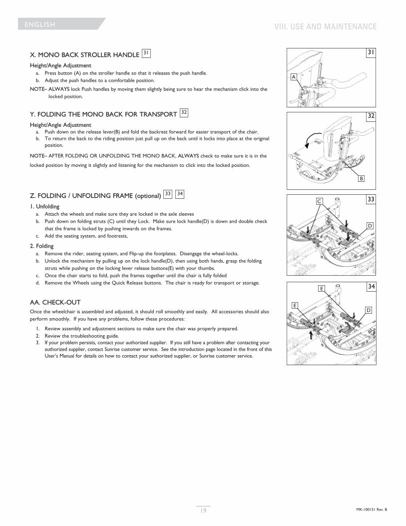
X. MONO BACK STROLLER HANDLE
Height/Angle Adjustmenta. Press button (A) on the stroller handle so that it releases the push handle.b. Adjust the push handles to a comfortable position.
NOTE– ALWAYS lock Push handles by moving them slightly being sure to hear the mechanism click into thelocked position.
Y. FOLDING THE MONO BACK FOR TRANSPORT
Height/Angle Adjustmenta. Push down on the release lever(B) and fold the backrest forward for easier transport of the chair.b. To return the back to the riding position just pull up on the back until it locks into place at the original
position.
NOTE– AFTER FOLDING OR UNFOLDING THE MONO BACK, ALWAYS check to make sure it is in the
locked position by moving it slightly and listening for the mechanism to click into the locked position.
Z. FOLDING / UNFOLDING FRAME (optional)
1. Unfoldinga. Attach the wheels and make sure they are locked in the axle sleevesb. Push down on folding struts (C) until they Lock. Make sure lock handle(D) is down and double check
that the frame is locked by pushing inwards on the frames.c. Add the seating system, and footrests,
2. Foldinga. Remove the rider, seating system, and Flip-up the footplates. Disengage the wheel-locks.b. Unlock the mechanism by pulling up on the lock handle(D), then using both hands, grasp the folding
struts while pushing on the locking lever release buttons(E) with your thumbs.c. Once the chair starts to fold, push the frames together until the chair is fully foldedd. Remove the Wheels using the Quick Release buttons. The chair is ready for transport or storage.
AA. CHECK-OUTOnce the wheelchair is assembled and adjusted, it should roll smoothly and easily. All accessories should alsoperform smoothly. If you have any problems, follow these procedures:
1. Review assembly and adjustment sections to make sure the chair was properly prepared.2. Review the troubleshooting guide.3. If your problem persists, contact your authorized supplier. If you still have a problem after contacting your
authorized supplier, contact Sunrise customer service. See the introduction page located in the front of thisUser’s Manual for details on how to contact your authorized supplier, or Sunrise customer service.
31
32
33 34
31
A
32
B
33C
D
34E
DE
VIII. USE AND MAINTENANCE
MK-100151 Rev. B 20
ENGLISH
WARNING
The owner of this chair is responsible for makiing sure that it has been setup and adjusted by a trained service
professional under the advice of a healthcare advisor. Service or adjustments should only be done with the
advice of a healthcare professional. Always use parts and accessories that have been recommended and
approved by Sunrise Medical when servicing this chair.
A. DEALER SERVICE INTRODUCTION1. At least once per year, this chair should have a complete inspection, safety check, and regular service
made by an authorized dealer.2. If you have discovered a worn, bent, or damaged part, repair or replace them with recommended parts
before returning this chair to service.. 3. All major maintenance and repair work should be done by the authorized dealer.
B. CRITICAL MAINTENANCE TIPS
1. Torque settings:A torque setting is the optimum tightening which should be made on a particular fastener. It is important touse proper torque settings where specified. When not specified, torque settings should be 60 in-lbs
2. Dealer Service and Adjustment Reference materials:Go to www.sunrisemedical.com for parts manuals, instruction sheets, and instructional videos that will aid in therepair of the Quickie/Zippie Family of wheelchairs.
C. CLEANING
1. Paint Finisha. Clean the painted surfaces with mild soap or detergent.b. Protect the paint with a coat of non-abrasive auto wax.
2. Axles and Moving Partsa. Clean around axles and moving parts with a slightly damp (not wet) cloth.b. Wipe off or blow away any fluff, dust or dirt on axles or moving parts. c. DO NOT USE 3 in 1 oil, or WD-40 ® for lubrication. Only use Teflon based Lubricant when working
on this wheelchair.
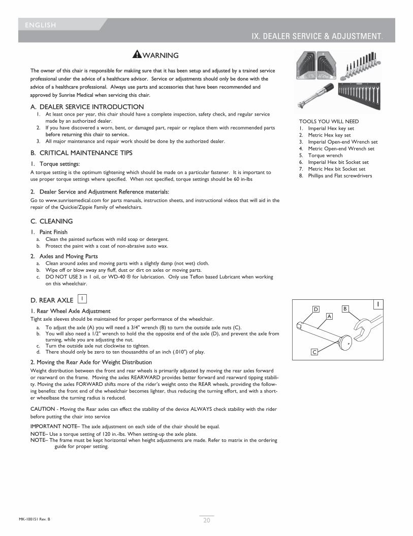
D. REAR AXLE
1. Rear Wheel Axle Adjustment Tight axle sleeves should be maintained for proper performance of the wheelchair.
a. To adjust the axle (A) you will need a 3/4" wrench (B) to turn the outside axle nuts (C).b. You will also need a 1/2" wrench to hold the the opposite end of the axle (D), and prevent the axle from
turning, while you are adjusting the nut.c. Turn the outside axle nut clockwise to tighten.d. There should only be zero to ten thousandths of an inch (.010") of play.
2. Moving the Rear Axle for Weight DistributionWeight distribution between the front and rear wheels is primarily adjusted by moving the rear axles forwardor rearward on the frame. Moving the axles REARWARD provides better forward and rearward tipping stabili-ty. Moving the axles FORWARD shifts more of the rider’s weight onto the REAR wheels, providing the follow-ing benefits: the front end of the wheelchair becomes lighter, thus reducing the turning effort, and with a short-er wheelbase the turning radius is reduced.
CAUTION - Moving the Rear axles can effect the stability of the device ALWAYS check stability with the riderbefore putting the chair into service
IMPORTANT NOTE– The axle adjustment on each side of the chair should be equal.NOTE– Use a torque setting of 120 in.-lbs. When setting-up the axle plate.NOTE– The frame must be kept horizontal when height adjustments are made. Refer to matrix in the ordering
guide for proper setting.
1
IX. DEALER SERVICE & ADJUSTMENT.
TOOLS YOU WILL NEED1. Imperial Hex key set2. Metric Hex key set3. Imperial Open-end Wrench set4. Metric Open-end Wrench set5. Torque wrench6. Imperial Hex bit Socket set7. Metric Hex bit Socket set8. Phillips and Flat screwdrivers
1
AB
C
D
MK-100151 Rev. B21
ENGLISH
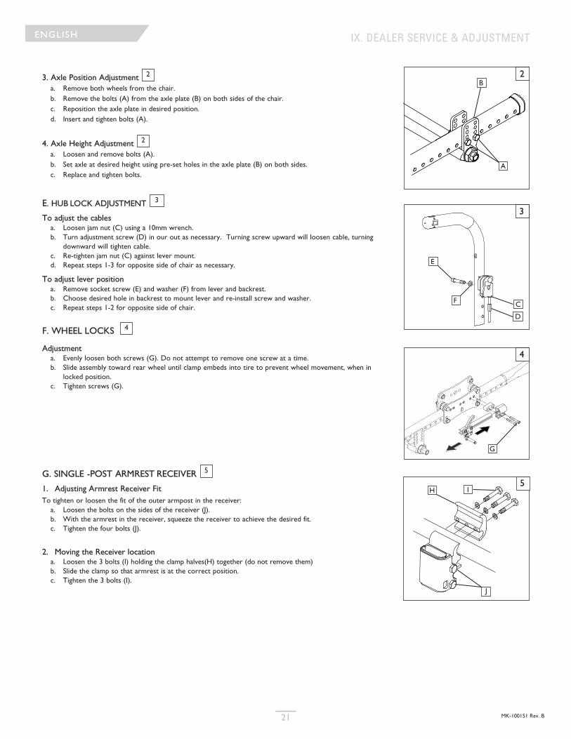
3. Axle Position Adjustmenta. Remove both wheels from the chair. b. Remove the bolts (A) from the axle plate (B) on both sides of the chair.c. Reposition the axle plate in desired position.d. Insert and tighten bolts (A).
4. Axle Height Adjustmenta. Loosen and remove bolts (A).b. Set axle at desired height using pre-set holes in the axle plate (B) on both sides.c. Replace and tighten bolts.
E. HUB LOCK ADJUSTMENT
To adjust the cablesa. Loosen jam nut (C) using a 10mm wrench.b. Turn adjustment screw (D) in our out as necessary. Turning screw upward will loosen cable, turning
downward will tighten cable.c. Re-tighten jam nut (C) against lever mount.d. Repeat steps 1-3 for opposite side of chair as necessary.
To adjust lever positiona. Remove socket screw (E) and washer (F) from lever and backrest.b. Choose desired hole in backrest to mount lever and re-install screw and washer.c. Repeat steps 1-2 for opposite side of chair.
F. WHEEL LOCKS
Adjustmenta. Evenly loosen both screws (G). Do not attempt to remove one screw at a time.b. Slide assembly toward rear wheel until clamp embeds into tire to prevent wheel movement, when in
locked position.c. Tighten screws (G).
G. SINGLE -POST ARMREST RECEIVER
1. Adjusting Armrest Receiver FitTo tighten or loosen the fit of the outer armpost in the receiver:a. Loosen the bolts on the sides of the receiver (J).b. With the armrest in the receiver, squeeze the receiver to achieve the desired fit.c. Tighten the four bolts (J).
2. Moving the Receiver locationa. Loosen the 3 bolts (I) holding the clamp halves(H) together (do not remove them) b. Slide the clamp so that armrest is at the correct position.c. Tighten the 3 bolts (I).
3
4
5
2
2
IX. DEALER SERVICE & ADJUSTMENT
2
3
4
5
A
B
E
F C
D
G
IH
J
MK-100151 Rev. B 22
ENGLISH
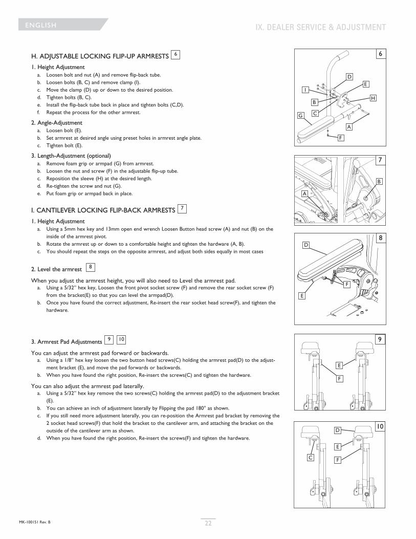
H. ADJUSTABLE LOCKING FLIP-UP ARMRESTS
1. Height Adjustmenta. Loosen bolt and nut (A) and remove flip-back tube.b. Loosen bolts (B, C) and remove clamp (I).c. Move the clamp (D) up or down to the desired position.d. Tighten bolts (B, C). e. Install the flip-back tube back in place and tighten bolts (C,D).f. Repeat the process for the other armrest.
2. Angle-Adjustmenta. Loosen bolt (E).b. Set armrest at desired angle using preset holes in armrest angle plate.c. Tighten bolt (E).
3. Length-Adjustment (optional)a. Remove foam grip or armpad (G) from armrest.b. Loosen the nut and screw (F) in the adjustable flip-up tube.c. Reposition the sleeve (H) at the desired length.d. Re-tighten the screw and nut (G).e. Put foam grip or armpad back in place.
I. CANTILEVER LOCKING FLIP-BACK ARMRESTS
1. Height Adjustmenta. Using a 5mm hex key and 13mm open end wrench Loosen Button head screw (A) and nut (B) on the
inside of the armrest pivot. b. Rotate the armrest up or down to a comfortable height and tighten the hardware (A, B).c. You should repeat the steps on the opposite armrest, and adjust both sides equally in most cases
2. Level the armrest
When you adjust the armrest height, you will also need to Level the armrest pad.a. Using a 5/32” hex key, Loosen the front pivot socket screw (F) and remove the rear socket screw (F)
from the bracket(E) so that you can level the armpad(D). b. Once you have found the correct adjustment, Re-insert the rear socket head screw(F), and tighten the
hardware.
3. Armrest Pad Adjustments
You can adjust the armrest pad forward or backwards.a. Using a 1/8” hex key loosen the two button head screws(C) holding the armrest pad(D) to the adjust-
ment bracket (E), and move the pad forwards or backwards.b. When you have found the right position, Re-insert the screws(C) and tighten the hardware.
You can also adjust the armrest pad laterally.a. Using a 5/32” hex key remove the two screws(C) holding the armrest pad(D) to the adjustment bracket
(E).b. You can achieve an inch of adjustment laterally by Flipping the pad 180° as shown.c. If you still need more adjustment laterally, you can re-position the Armrest pad bracket by removing the
2 socket head screws(F) that hold the bracket to the cantilever arm, and attaching the bracket on theoutside of the cantilever arm as shown.
d. When you have found the right position, Re-insert the screws(F) and tighten the hardware.
6
7
8
109
IX. DEALER SERVICE & ADJUSTMENT
6
E
F
I
G
H
A
B
C
D
10
9
7
8
A
B
C
D
E
F
E
F
E
F
D
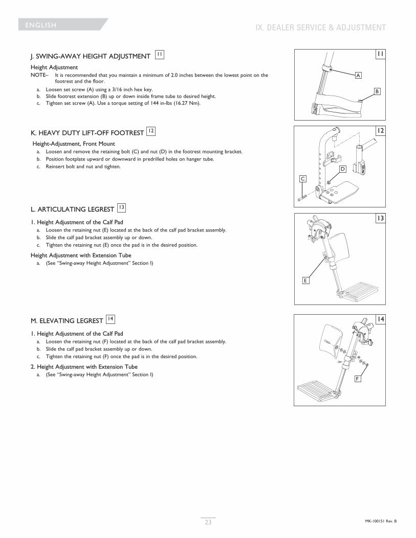
MK-100151 Rev. B23
ENGLISH
J. SWING-AWAY HEIGHT ADJUSTMENT
Height Adjustment NOTE– It is recommended that you maintain a minimum of 2.0 inches between the lowest point on the
footrest and the floor.
a. Loosen set screw (A) using a 3/16 inch hex key.b. Slide footrest extension (B) up or down inside frame tube to desired height.c. Tighten set screw (A). Use a torque setting of 144 in-lbs (16.27 Nm).
K. HEAVY DUTY LIFT-OFF FOOTREST
Height-Adjustment, Front Mount a. Loosen and remove the retaining bolt (C) and nut (D) in the footrest mounting bracket.b. Position footplate upward or downward in predrilled holes on hanger tube.c. Reinsert bolt and nut and tighten.
L. ARTICULATING LEGREST
1. Height Adjustment of the Calf Pad a. Loosen the retaining nut (E) located at the back of the calf pad bracket assembly. b. Slide the calf pad bracket assembly up or down.c. Tighten the retaining nut (E) once the pad is in the desired position.
Height Adjustment with Extension Tubea. (See “Swing-away Height Adjustment” Section I)
M. ELEVATING LEGREST
1. Height Adjustment of the Calf Pad a. Loosen the retaining nut (F) located at the back of the calf pad bracket assembly. b. Slide the calf pad bracket assembly up or down.c. Tighten the retaining nut (F) once the pad is in the desired position.
2. Height Adjustment with Extension Tube a. (See “Swing-away Height Adjustment” Section I)
11
12
13
14
IX. DEALER SERVICE & ADJUSTMENT
11
12
13
14
A
B
C
D
F
E
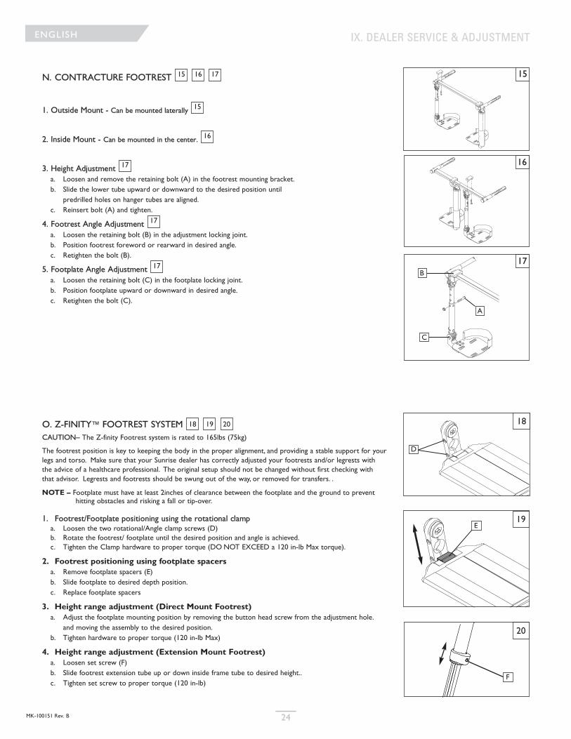
MK-100151 Rev. B 24
ENGLISH
N. CONTRACTURE FOOTREST
1. Outside Mount - Can be mounted laterally
2. Inside Mount - Can be mounted in the center.
3. Height Adjustmenta. Loosen and remove the retaining bolt (A) in the footrest mounting bracket.b. Slide the lower tube upward or downward to the desired position until
predrilled holes on hanger tubes are aligned.c. Reinsert bolt (A) and tighten.
4. Footrest Angle Adjustment a. Loosen the retaining bolt (B) in the adjustment locking joint.b. Position footrest foreword or rearward in desired angle.c. Retighten the bolt (B).
5. Footplate Angle Adjustment a. Loosen the retaining bolt (C) in the footplate locking joint.b. Position footplate upward or downward in desired angle.c. Retighten the bolt (C).
O. Z-FINITY™ FOOTREST SYSTEM CAUTION– The Z-finity Footrest system is rated to 165lbs (75kg)
The footrest position is key to keeping the body in the proper alignment, and providing a stable support for yourlegs and torso. Make sure that your Sunrise dealer has correctly adjusted your footrests and/or legrests withthe advice of a healthcare professional. The original setup should not be changed without first checking withthat advisor. Legrests and footrests should be swung out of the way, or removed for transfers. .
NOTE – Footplate must have at least 2inches of clearance between the footplate and the ground to preventhitting obstacles and risking a fall or tip-over.
1. Footrest/Footplate positioning using the rotational clampa. Loosen the two rotational/Angle clamp screws (D) b. Rotate the footrest/ footplate until the desired position and angle is achieved.c. Tighten the Clamp hardware to proper torque (DO NOT EXCEED a 120 in-lb Max torque).
2. Footrest positioning using footplate spacersa. Remove footplate spacers (E)b. Slide footplate to desired depth position.c. Replace footplate spacers
3. Height range adjustment (Direct Mount Footrest)a. Adjust the footplate mounting position by removing the button head screw from the adjustment hole.
and moving the assembly to the desired position.b. Tighten hardware to proper torque (120 in-lb Max)
4. Height range adjustment (Extension Mount Footrest)a. Loosen set screw (F)b. Slide footrest extension tube up or down inside frame tube to desired height..c. Tighten set screw to proper torque (120 in-lb)
171615
15
16
17
17
17
18 19 20
IX. DEALER SERVICE & ADJUSTMENT
15
16
17
A
B
C
20
F
19
18
D
E
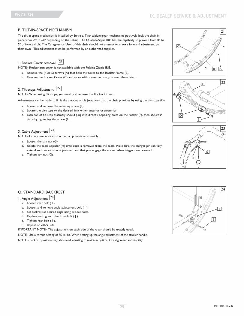
MK-100151 Rev. B25
ENGLISH
P. TILT-IN-SPACE MECHANISM The tilt-in-space mechanism is installed by Sunrise. Two cable/trigger mechanisms positively lock the chair inplace from -5º to 60º depending on the set-up. The Quickie/Zippie IRIS has the capability to provide from 0º to5º of forward tilt. The Caregiver or User of this chair should not attempt to make a forward adjustment ontheir own. This adjustment must be performed by an authorized supplier.
1. Rocker Cover removal NOTE– Rocker arm cover is not available with the Folding Zippie IRIS.
a. Remove the (4 or 5) screws (A) that hold the cover to the Rocker Frame (B).b. Remove the Rocker Cover (C) and store with screws in case you need them later.
2. Tilt-stops AdjustmentNOTE– When using tilt stops, you must first remove the Rocker Cover.
Adjustments can be made to limit the amount of tilt (rotation) that the chair provides by using the tilt-stops (D).
a. Loosen and remove the retaining screw (E).b. Locate the tilt-stops to the desired limit either anterior or posterior.c. Each half of tilt stop assembly should plug into directly opposing holes on the rocker (F), then secure in
place by tightening the screw (E).
3. Cable AdjustmentNOTE– Do not use lubricants on the components or assembly.
a. Loosen the jam nut (G).b. Rotate the cable adjuster (H) until slack is removed from the cable. Make sure the plunger pin can fully
extend and retract after adjustment and that pins engage the rocker when triggers are released.c. Tighten jam nut (G).
Q. STANDARD BACKREST
1. Angle Adjustmenta. Loosen rear bolt ( I ).b. Loosen and remove angle adjustment bolt ( J ).c. Set backrest at desired angle using pre-set holes.d. Replace and tighten the front bolt ( J ).e. Tighten rear bolt ( I ).f. Repeat on other side.
IMPORTANT NOTE– The adjustment on each side of the chair should be exactly equal.
NOTE -Use a torque setting of 75 in.-lbs. When setting-up the angle adjustment of the stroller handle.
NOTE - Backrest position may also need adjusting to maintain optimal CG alignment and stability.
21
22
23
24
IX. DEALER SERVICE & ADJUSTMENT
21
22
DE
F
23
H
G
C
B A
24
I
J
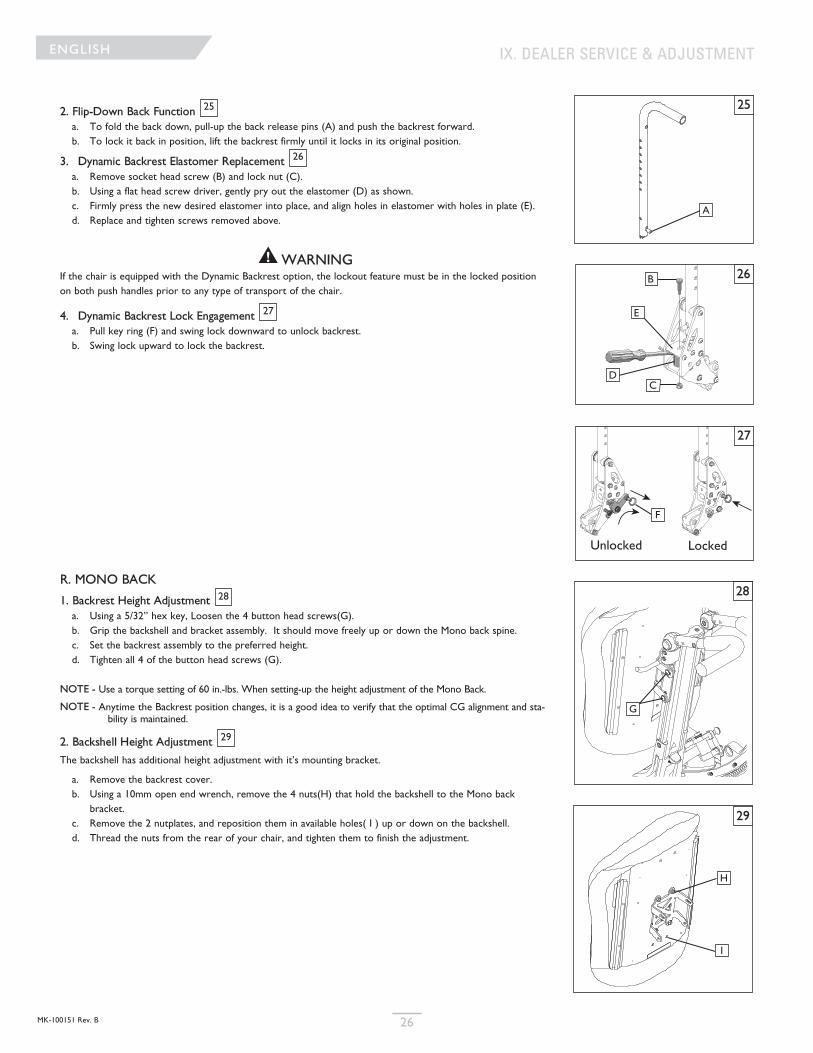
MK-100151 Rev. B 26
ENGLISH
2. Flip-Down Back Functiona. To fold the back down, pull-up the back release pins (A) and push the backrest forward.b. To lock it back in position, lift the backrest firmly until it locks in its original position.
3. Dynamic Backrest Elastomer Replacementa. Remove socket head screw (B) and lock nut (C).b. Using a flat head screw driver, gently pry out the elastomer (D) as shown.c. Firmly press the new desired elastomer into place, and align holes in elastomer with holes in plate (E).d. Replace and tighten screws removed above.
WARNINGIf the chair is equipped with the Dynamic Backrest option, the lockout feature must be in the locked positionon both push handles prior to any type of transport of the chair.
4. Dynamic Backrest Lock Engagementa. Pull key ring (F) and swing lock downward to unlock backrest.b. Swing lock upward to lock the backrest.
R. MONO BACK
1. Backrest Height Adjustmenta. Using a 5/32” hex key, Loosen the 4 button head screws(G). b. Grip the backshell and bracket assembly. It should move freely up or down the Mono back spine. c. Set the backrest assembly to the preferred height.d. Tighten all 4 of the button head screws (G).
NOTE - Use a torque setting of 60 in.-lbs. When setting-up the height adjustment of the Mono Back.
NOTE - Anytime the Backrest position changes, it is a good idea to verify that the optimal CG alignment and sta-bility is maintained.
2. Backshell Height Adjustment
The backshell has additional height adjustment with it’s mounting bracket.
a. Remove the backrest cover.b. Using a 10mm open end wrench, remove the 4 nuts(H) that hold the backshell to the Mono back
bracket.c. Remove the 2 nutplates, and reposition them in available holes( I ) up or down on the backshell.d. Thread the nuts from the rear of your chair, and tighten them to finish the adjustment.
27
28
25
26
29
IX. DEALER SERVICE & ADJUSTMENT
28
G
26
27
B
CD
E
F
Unlocked Locked
25
A
29
H
I
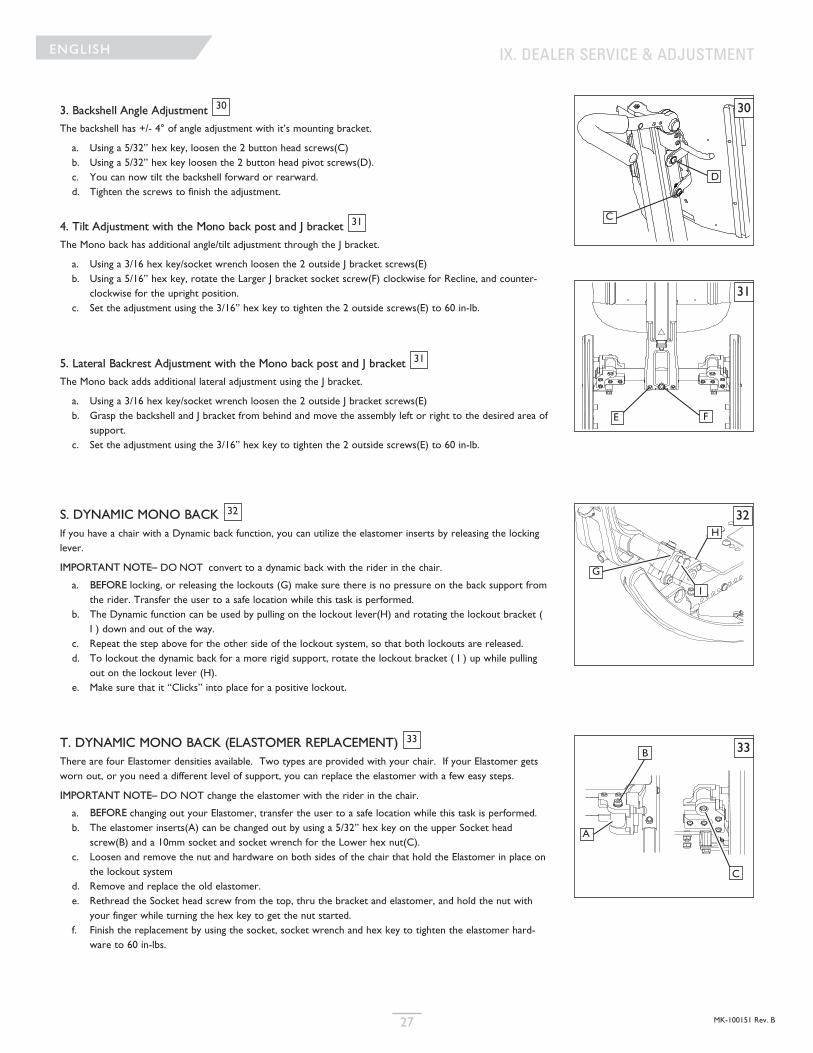
MK-100151 Rev. B27
ENGLISH
3. Backshell Angle Adjustment
The backshell has +/- 4° of angle adjustment with it’s mounting bracket.
a. Using a 5/32” hex key, loosen the 2 button head screws(C) b. Using a 5/32” hex key loosen the 2 button head pivot screws(D).c. You can now tilt the backshell forward or rearward.d. Tighten the screws to finish the adjustment.
4. Tilt Adjustment with the Mono back post and J bracket
The Mono back has additional angle/tilt adjustment through the J bracket.
a. Using a 3/16 hex key/socket wrench loosen the 2 outside J bracket screws(E)b. Using a 5/16” hex key, rotate the Larger J bracket socket screw(F) clockwise for Recline, and counter-
clockwise for the upright position. c. Set the adjustment using the 3/16” hex key to tighten the 2 outside screws(E) to 60 in-lb.
5. Lateral Backrest Adjustment with the Mono back post and J bracket
The Mono back adds additional lateral adjustment using the J bracket.
a. Using a 3/16 hex key/socket wrench loosen the 2 outside J bracket screws(E)b. Grasp the backshell and J bracket from behind and move the assembly left or right to the desired area of
support.c. Set the adjustment using the 3/16” hex key to tighten the 2 outside screws(E) to 60 in-lb.
S. DYNAMIC MONO BACK If you have a chair with a Dynamic back function, you can utilize the elastomer inserts by releasing the lockinglever.
IMPORTANT NOTE– DO NOT convert to a dynamic back with the rider in the chair.
a. BEFORE locking, or releasing the lockouts (G) make sure there is no pressure on the back support fromthe rider. Transfer the user to a safe location while this task is performed.
b. The Dynamic function can be used by pulling on the lockout lever(H) and rotating the lockout bracket (I ) down and out of the way.
c. Repeat the step above for the other side of the lockout system, so that both lockouts are released.d. To lockout the dynamic back for a more rigid support, rotate the lockout bracket ( I ) up while pulling
out on the lockout lever (H).e. Make sure that it “Clicks” into place for a positive lockout.
T. DYNAMIC MONO BACK (ELASTOMER REPLACEMENT) There are four Elastomer densities available. Two types are provided with your chair. If your Elastomer getsworn out, or you need a different level of support, you can replace the elastomer with a few easy steps.
IMPORTANT NOTE– DO NOT change the elastomer with the rider in the chair.
a. BEFORE changing out your Elastomer, transfer the user to a safe location while this task is performed.b. The elastomer inserts(A) can be changed out by using a 5/32” hex key on the upper Socket head
screw(B) and a 10mm socket and socket wrench for the Lower hex nut(C). c. Loosen and remove the nut and hardware on both sides of the chair that hold the Elastomer in place on
the lockout system d. Remove and replace the old elastomer.e. Rethread the Socket head screw from the top, thru the bracket and elastomer, and hold the nut with
your finger while turning the hex key to get the nut started.f. Finish the replacement by using the socket, socket wrench and hex key to tighten the elastomer hard-
ware to 60 in-lbs.
31
31
30
32
33
IX. DEALER SERVICE & ADJUSTMENT
30
31
D
C
FE
32H
G
I
33B
A
C
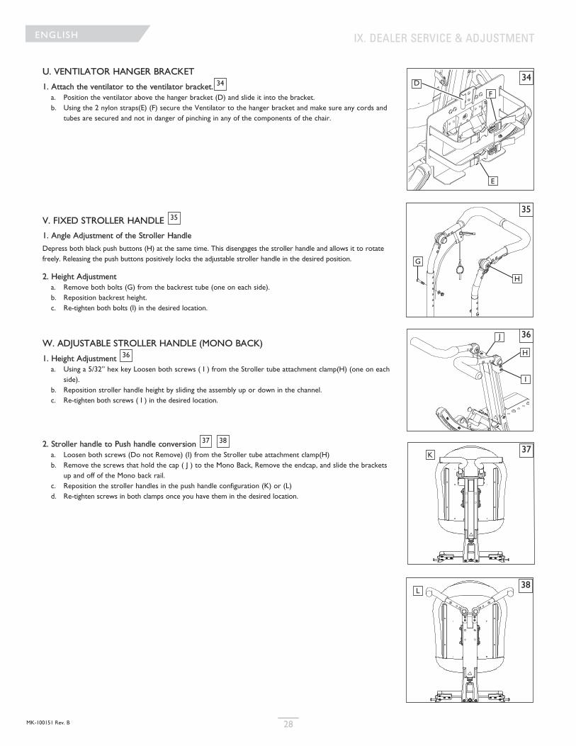
MK-100151 Rev. B 28
ENGLISH
U. VENTILATOR HANGER BRACKET
1. Attach the ventilator to the ventilator bracket.a. Position the ventilator above the hanger bracket (D) and slide it into the bracket.b. Using the 2 nylon straps(E) (F) secure the Ventilator to the hanger bracket and make sure any cords and
tubes are secured and not in danger of pinching in any of the components of the chair.
V. FIXED STROLLER HANDLE
1. Angle Adjustment of the Stroller Handle
Depress both black push buttons (H) at the same time. This disengages the stroller handle and allows it to rotatefreely. Releasing the push buttons positively locks the adjustable stroller handle in the desired position.
2. Height Adjustmenta. Remove both bolts (G) from the backrest tube (one on each side).b. Reposition backrest height.c. Re-tighten both bolts (I) in the desired location.
W. ADJUSTABLE STROLLER HANDLE (MONO BACK)
1. Height Adjustment a. Using a 5/32” hex key Loosen both screws ( I ) from the Stroller tube attachment clamp(H) (one on each
side).b. Reposition stroller handle height by sliding the assembly up or down in the channel.c. Re-tighten both screws ( I ) in the desired location.
2. Stroller handle to Push handle conversiona. Loosen both screws (Do not Remove) (I) from the Stroller tube attachment clamp(H)b. Remove the screws that hold the cap ( J ) to the Mono Back, Remove the endcap, and slide the brackets
up and off of the Mono back rail.c. Reposition the stroller handles in the push handle configuration (K) or (L)d. Re-tighten screws in both clamps once you have them in the desired location.
34
35
36
3837
IX. DEALER SERVICE & ADJUSTMENT
34
F
D
E
35
H
G
36
37
H
I
J
38
K
L
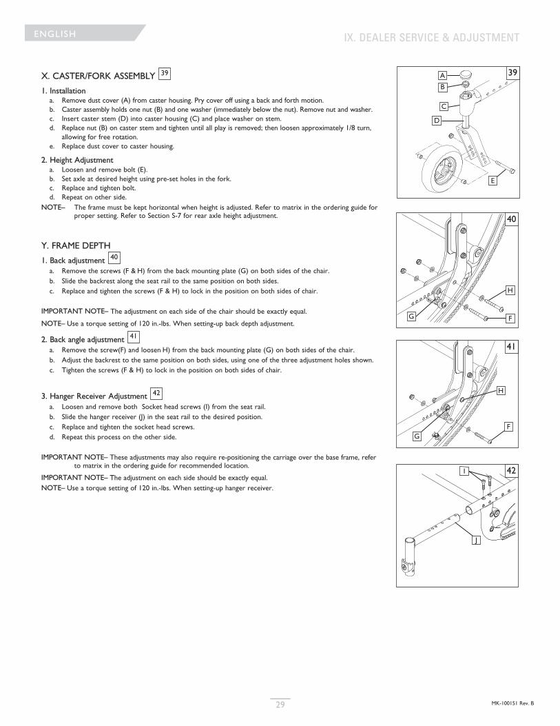
MK-100151 Rev. B29
ENGLISH
X. CASTER/FORK ASSEMBLY
1. Installationa. Remove dust cover (A) from caster housing. Pry cover off using a back and forth motion.b. Caster assembly holds one nut (B) and one washer (immediately below the nut). Remove nut and washer.c. Insert caster stem (D) into caster housing (C) and place washer on stem.d. Replace nut (B) on caster stem and tighten until all play is removed; then loosen approximately 1/8 turn,
allowing for free rotation.e. Replace dust cover to caster housing.
2. Height Adjustmenta. Loosen and remove bolt (E).b. Set axle at desired height using pre-set holes in the fork.c. Replace and tighten bolt.d. Repeat on other side.
NOTE– The frame must be kept horizontal when height is adjusted. Refer to matrix in the ordering guide forproper setting. Refer to Section S-7 for rear axle height adjustment.
Y. FRAME DEPTH
1. Back adjustmenta. Remove the screws (F & H) from the back mounting plate (G) on both sides of the chair.b. Slide the backrest along the seat rail to the same position on both sides.c. Replace and tighten the screws (F & H) to lock in the position on both sides of chair.
IMPORTANT NOTE– The adjustment on each side of the chair should be exactly equal.
NOTE– Use a torque setting of 120 in.-lbs. When setting-up back depth adjustment.
2. Back angle adjustmenta. Remove the screw(F) and loosen H) from the back mounting plate (G) on both sides of the chair.b. Adjust the backrest to the same position on both sides, using one of the three adjustment holes shown.c. Tighten the screws (F & H) to lock in the position on both sides of chair.
3. Hanger Receiver Adjustmenta. Loosen and remove both Socket head screws (I) from the seat rail.b. Slide the hanger receiver (J) in the seat rail to the desired position.c. Replace and tighten the socket head screws.d. Repeat this process on the other side.
IMPORTANT NOTE– These adjustments may also require re-positioning the carriage over the base frame, referto matrix in the ordering guide for recommended location.
IMPORTANT NOTE– The adjustment on each side should be exactly equal.NOTE– Use a torque setting of 120 in.-lbs. When setting-up hanger receiver.
39
40
41
42
IX. DEALER SERVICE & ADJUSTMENT
39A
B
E
D
C
40
41
42
FG
H
I
J
FG
H
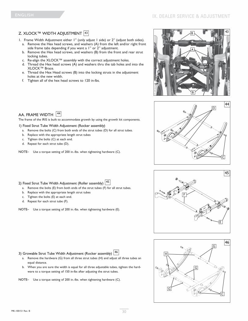
MK-100151 Rev. B 30
ENGLISH IX. DEALER SERVICE & ADJUSTMENT
Z. XLOCK™ WIDTH ADJUSTMENT
1. Frame Width Adjustment either 1” (only adjust 1 side) or 2” (adjust both sides).a. Remove the Hex head screws, and washers (A) from the left and/or right front
side frame tabs depending if you want a 1” or 2” adjustment.b. Remove the Hex head screws, and washers (B) from the front and rear strut
locking tubes. c. Re-align the XLOCK™ assembly with the correct adjustment holes.d. Thread the Hex head screws (A) and washers thru the tab holes and into the
XLOCK™ Brace.e. Thread the Hex Head screws (B) into the locking struts in the adjustment
holes at the new width.f. Tighten all of the hex head screws to 120 in-lbs.
AA. FRAME WIDTH The frame of the IRIS is built to accommodate growth by using the growth kit components.
1) Fixed Strut Tube Width Adjustment (Rocker assembly)a. Remove the bolts (C) from both ends of the strut tubes (D) for all strut tubes.b. Replace with the appropriate length strut tubesc. Tighten the bolts (C) at each end.d. Repeat for each strut tube (D).
NOTE– Use a torque setting of 200 in.-lbs. when tightening hardware (C).
2) Fixed Strut Tube Width Adjustment (Roller assembly) a. Remove the bolts (E) from both ends of the strut tubes (F) for all strut tubes.b. Replace with the appropriate length strut tubesc. Tighten the bolts (E) at each end.d. Repeat for each strut tube (F).
NOTE– Use a torque setting of 200 in.-lbs. when tightening hardware (E).
3) Growable Strut Tube Width Adjustment (Rocker assembly) a. Remove the hardware (G) from all three strut tubes (H) and adjust all three tubes an
equal distance.b. When you are sure the width is equal for all three adjustable tubes, tighten the hard-
ware to a torque setting of 150 in-lbs after adjusting the strut tubes.
NOTE– Use a torque setting of 200 in.-lbs. when tightening hardware (C).
43
44
45
46
43
44
45
C
F
D
E
46
H
G
C
A
B
B
G
G
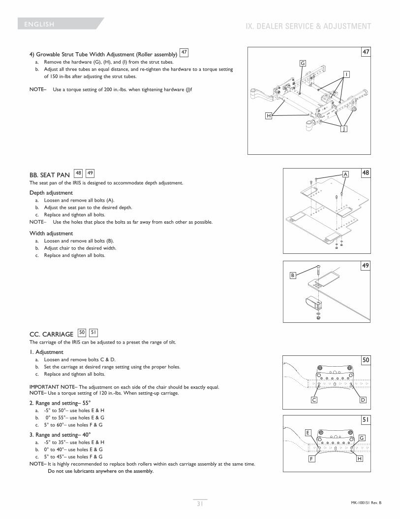
MK-100151 Rev. B31
ENGLISH IX. DEALER SERVICE & ADJUSTMENT
4) Growable Strut Tube Width Adjustment (Roller assembly) a. Remove the hardware (G), (H), and (I) from the strut tubes.b. Adjust all three tubes an equal distance, and re-tighten the hardware to a torque setting
of 150 in-lbs after adjusting the strut tubes.
NOTE– Use a torque setting of 200 in.-lbs. when tightening hardware (J)f
47 47
H
G
I
J
BB. SEAT PAN The seat pan of the IRIS is designed to accommodate depth adjustment.
Depth adjustmenta. Loosen and remove all bolts (A).b. Adjust the seat pan to the desired depth.c. Replace and tighten all bolts.
NOTE– Use the holes that place the bolts as far away from each other as possible.
Width adjustmenta. Loosen and remove all bolts (B).b. Adjust chair to the desired width.c. Replace and tighten all bolts.
CC. CARRIAGE The carriage of the IRIS can be adjusted to a preset the range of tilt.
1. Adjustmenta. Loosen and remove bolts C & D.b. Set the carriage at desired range setting using the proper holes. c. Replace and tighten all bolts.
IMPORTANT NOTE– The adjustment on each side of the chair should be exactly equal.NOTE– Use a torque setting of 120 in.-lbs. When setting-up carriage.
2. Range and setting– 55°a. -5° to 50°– use holes E & Hb. 0° to 55°– use holes E & Gc. 5° to 60°– use holes F & G
3. Range and setting– 40°a. -5° to 35°– use holes E & Hb. 0° to 40°– use holes E & Gc. 5° to 45°– use holes F & G
NOTE– It is highly recommended to replace both rollers within each carriage assembly at the same time.Do not use lubricants anywhere on the assembly.
4948
5150
48
49
A
B
50
51
C D
E
F
G
H
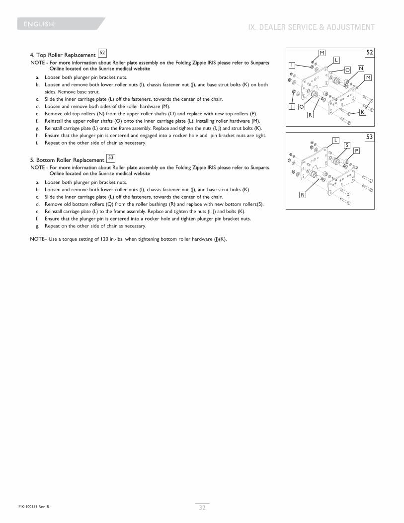
MK-100151 Rev. B 32
ENGLISHENGLISH IX. DEALER SERVICE & ADJUSTMENT
4. Top Roller ReplacementNOTE - For more information about Roller plate assembly on the Folding Zippie IRIS please refer to Sunparts
Online located on the Sunrise medical website
a. Loosen both plunger pin bracket nuts.b. Loosen and remove both lower roller nuts (I), chassis fastener nut (J), and base strut bolts (K) on both
sides. Remove base strut.c. Slide the inner carriage plate (L) off the fasteners, towards the center of the chair.d. Loosen and remove both sides of the roller hardware (M). e. Remove old top rollers (N) from the upper roller shafts (O) and replace with new top rollers (P).f. Reinstall the upper roller shafts (O) onto the inner carriage plate (L), installing roller hardware (M). g. Reinstall carriage plate (L) onto the frame assembly. Replace and tighten the nuts (I, J) and strut bolts (K). h. Ensure that the plunger pin is centered and engaged into a rocker hole and pin bracket nuts are tight.i. Repeat on the other side of chair as necessary.
5. Bottom Roller ReplacementNOTE - For more information about Roller plate assembly on the Folding Zippie IRIS please refer to Sunparts
Online located on the Sunrise medical website
a. Loosen both plunger pin bracket nuts.b. Loosen and remove both lower roller nuts (I), chassis fastener nut (J), and base strut bolts (K).c. Slide the inner carriage plate (L) off the fasteners, towards the center of the chair.d. Remove old bottom rollers (Q) from the roller bushings (R) and replace with new bottom rollers(S). e. Reinstall carriage plate (L) to the frame assembly. Replace and tighten the nuts (I, J) and bolts (K).f. Ensure that the plunger pin is centered into a rocker hole and tighten plunger pin bracket nuts.g. Repeat on the other side of chair as necessary.
NOTE– Use a torque setting of 120 in.-lbs. when tightening bottom roller hardware (J)(K).
52
53
52
53
IO
M
N
L
KJ
R
P
Q
LS
R
M
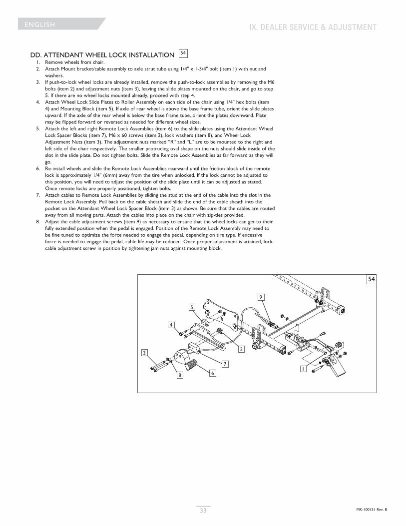
MK-100151 Rev. B33
ENGLISH
DD. ATTENDANT WHEEL LOCK INSTALLATION1. Remove wheels from chair.2. Attach Mount bracket/cable assembly to axle strut tube using 1/4" x 1-3/4" bolt (item 1) with nut and
washers.3. If push-to-lock wheel locks are already installed, remove the push-to-lock assemblies by removing the M6
bolts (item 2) and adjustment nuts (item 3), leaving the slide plates mounted on the chair, and go to step5. If there are no wheel locks mounted already, proceed with step 4.
4. Attach Wheel Lock Slide Plates to Roller Assembly on each side of the chair using 1/4" hex bolts (item4) and Mounting Block (item 5). If axle of rear wheel is above the base frame tube, orient the slide platesupward. If the axle of the rear wheel is below the base frame tube, orient the plates downward. Platemay be flipped forward or reversed as needed for different wheel sizes.
5. Attach the left and right Remote Lock Assemblies (item 6) to the slide plates using the Attendant WheelLock Spacer Blocks (item 7), M6 x 60 screws (item 2), lock washers (item 8), and Wheel LockAdjustment Nuts (item 3). The adjustment nuts marked “R” and “L” are to be mounted to the right andleft side of the chair respectively. The smaller protruding oval shape on the nuts should slide inside of theslot in the slide plate. Do not tighten bolts. Slide the Remote Lock Assemblies as far forward as they willgo.
6. Re-install wheels and slide the Remote Lock Assemblies rearward until the friction block of the remotelock is approximately 1/4" (6mm) away from the tire when unlocked. If the lock cannot be adjusted tothis position, you will need to adjust the position of the slide plate until it can be adjusted as stated.Once remote locks are properly positioned, tighten bolts.
7. Attach cables to Remote Lock Assemblies by sliding the stud at the end of the cable into the slot in theRemote Lock Assembly. Pull back on the cable sheath and slide the end of the cable sheath into thepocket on the Attendant Wheel Lock Spacer Block (item 3) as shown. Be sure that the cables are routedaway from all moving parts. Attach the cables into place on the chair with zip-ties provided.
8. Adjust the cable adjustment screws (item 9) as necessary to ensure that the wheel locks can get to theirfully extended position when the pedal is engaged. Position of the Remote Lock Assembly may need tobe fine tuned to optimize the force needed to engage the pedal, depending on tire type. If excessiveforce is needed to engage the pedal, cable life may be reduced. Once proper adjustment is attained, lockcable adjustment screw in position by tightening jam nuts against mounting block.
54
IX. DEALER SERVICE & ADJUSTMENT
54
1
23
4
5
6
7
8
9
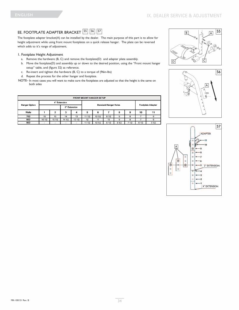
MK-100151 Rev. B 34
ENGLISH
EE. FOOTPLATE ADAPTER BRACKET The footplate adapter bracket(A) can be installed by the dealer. The main purpose of this part is to allow forheight adjustment while using front mount footplates on a quick release hanger. The plate can be reversedwhich adds to it’s range of adjustment.
1. Footplate Height Adjustmenta. Remove the hardware (B, C) and remove the footplate(D) and adapter plate assembly.b. Move the footplate(D) and assembly up or down to the desired position, using the “Front mount hanger
setup” table, and (figure 32) as reference.c. Re-insert and tighten the hardware (B, C) to a torque of (96in-lbs)d. Repeat the process for the other hanger and footplate.
NOTE– In most cases you will want to make sure the footplates are adjusted so that the height is the same onboth sides
575655
ENGLISH IX. DEALER SERVICE & ADJUSTMENT
55
56
57
A
B
CD
A
A
4” EXTENSION
2” EXTENSION
ADAPTER
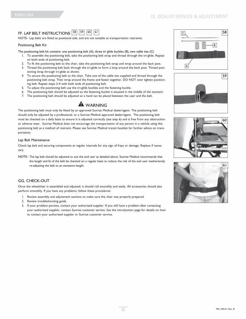
MK-100151 Rev. B35
ENGLISH
FF. LAP BELT INSTRUCTIONS NOTE– Lap belts are fitted as positional aids, and are not suitable as transportation restraints.
Positioning Belt Kit
The positioning belt kit contains: one positioning belt (A), three tri glide buckles (B), two cable ties (C)1. To assemble the positioning belt, take the positioning belt strap and thread through the tri-glide. Repeat
on both ends of positioning belt. 2. To fit the positioning belt to the chair, take the positioning belt strap and wrap around the back post.3. Thread the positioning belt back through the tri-glide to form a loop around the back post. Thread posi-
tioning strap through tri-glide as shown. 4. To secure the positioning belt to the chair. Take one of the cable ties supplied and thread through the
positioning belt strap. Then wrap around the frame and fasten together. DO NOT over tighten position-ing belt. Repeat steps 2-4 with both ends of positioning belt.
5. To adjust the positioning belt use the tri-glide buckles and the fastening buckle.6. The positioning belt should be adjusted so the fastening buckle is situated in the middle of the stomach.7. The positioning belt should be adjusted so a hand can be placed between the user and the belt.
WARNINGThe positioning belt must only be fitted by an approved Sunrise Medical dealer/agent. The positioning beltshould only be adjusted by a professional, or a Sunrise Medical approved dealer/agent. The positioning beltmust be checked on a daily basis to ensure it is adjusted correctly (see step 6) and is free from any obstructionor adverse wear. Sunrise Medical does not encourage the transportation of any person in a vehicle using thispositioning belt as a method of restraint. Please see Sunrise Medical transit booklet for further advice on trans-portation.
Lap Belt Maintenance
Check lap belt and securing components at regular intervals for any sign of frays or damage. Replace if neces-sary.
NOTE– The lap belt should be adjusted to suit the end user as detailed above. Sunrise Medical recommends thatthe length and fit of the belt be checked on a regular basis to reduce the risk of the end user inadvertentlyre-adjusting the belt to an excessive length.
GG. CHECK-OUTOnce the wheelchair is assembled and adjusted, it should roll smoothly and easily. All accessories should alsoperform smoothly. If you have any problems, follow these procedures:
1. Review assembly and adjustment sections to make sure the chair was properly prepared.2. Review troubleshooting guide.3. If your problem persists, contact your authorized supplier. If you still have a problem after contacting
your authorized supplier, contact Sunrise customer service. See the introduction page for details on howto contact your authorized supplier or Sunrise customer service.
61605958
IX. DEALER SERVICE & ADJUSTMENT
58
59
60
61
A
B
C
MK-100151 Rev. B 36
ENGLISH
X. SUNRISE LIMITED WARRANTY
A. FOR LIFETIME
Frame and cross-brace (if applicable) warranty:1. Although the anticipated useful service time of this wheelchair is five
years, Sunrise guarantees the frame and cross brace against defectsin material and workmanship for life or for as long as the originalpurchaser owns the chair.
2. This warranty does not apply if:a. The chair is subject to abuseb. The chair is not maintained as recommended in the owner’s
manualc. The chair is transferred to a different person from the original
owner
B. FOR ONE (1) YEARWe warrant all Sunrise-made parts and components of this wheelchairagainst defects in materials and workmanship for one year from the date offirst consumer purchase.
C. LIMITATIONS1. We do not warrant:a. Tires and tubes, upholstery, pads and push-handle grips.b. Damage from neglect, accident, misuse, or from improper
installation or repair.c. Products modified without Sunrise Medicals express written
consent.d. Damage from exceeding the weight limit.
2. This warranty is VOID if the original chair serial number tag isremoved or altered.
3. This warranty applies in the USA only. Check with your supplier tofind out if international warranties apply.
4. This warranty is not transferable and only applies to the first con-sumer purchase of this wheelchair through an authorized SunriseMedical dealer.
D. WHAT WE WILL DOOur sole liability is to repair or replace covered parts. This is the exclusiveremedy for consequential damages.
E. WHAT YOU MUST DO1. Obtain from us, while this warranty is in effect, prior approval forreturn or repair of covered parts.
2. Return the wheelchair or part(s), freight pre-paid, to SunriseMobility Products Division at: 2842 Business Park Avenue, Fresno,CA 93727-1328.
3. Pay the cost of labor to repair, remove or install parts.
F. NOTICE TO CONSUMER1. If allowed by law, this warranty is in place of any other warranty (written or oral, express or implied, including a warrantyof merchantability, or fitness for a particular purpose).
2. This warranty gives you certain legal rights. You may also haveother rights that vary from state to state.
G. ADDITIONAL WARRANTY INFORMATIONFor goods provided by Sunrise Medical Pty Ltd in Australia, our goodscome with a guarantee by Sunrise that cannot be excluded under theAustralian Consumer Law. You are entitled to a replacement or refundfor a major failure and for compensation for any other reasonably forsee-able loss or damage. You are also entitled to have the goods repaired orreplaced if the goods fail to be of acceptable quality and the failure doesnot amount to a major failure. The benefits to you given by this warrantyare in addition to your other rights and remedies under a law in relation tothe goods to which the warranty relates.
Record your serial number here for future reference:
___________________________________________