Embed Size (px)
Citation preview
ISS Ammonia Pump Failure, Recovery, and Lesson Learned – A Hydrodynamic Bearing Perspective
Robert J. Bruckner* and Richard A. Manco II**
Abstract
The design, development, and operation of long duration spaceflight hardware has become an evolutionary process in which meticulous attention to details and lessons learned from previous experiences play a critical role. Invaluable to this process is the ability to retrieve and examine spaceflight hardware that has experienced a premature failure. While these situations are rare and unfortunate, the failure investigation and recovery from the event serve a valuable purpose in advancing future space mechanism development. Such a scenario began on July 31, 2010 with the premature failure of an ammonia pump on the external active thermal control system of the International Space Station. The ground-based inspections of the returned pump and ensuing failure investigation revealed five potential bearing forces that were un-accounted for in the design phase and qualification testing of the pump. These forces could combine in a number of random orientations to overload the pump bearings leading to solid-surface contact, wear, and premature failure. The recovery plan identified one of these five forces as being related to the square of the operating speed of the pump and this fact was used to recover design life through a change in flight rules for the operation of the pump module. Through the course of the failure investigation, recovery, and follow-on assessment of pump wear life, design guidance has been developed to improve the life of future mechanically pumped thermal control systems for both human and robotic exploration missions.
Introduction
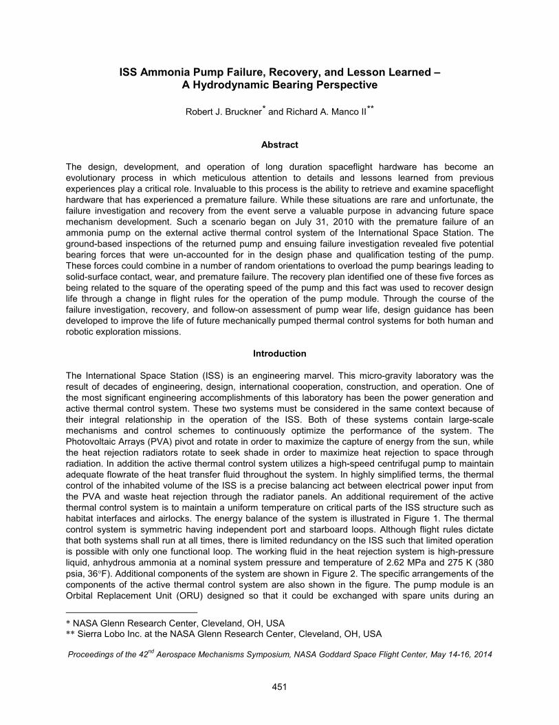
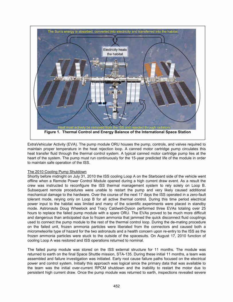
The International Space Station (ISS) is an engineering marvel. This micro-gravity laboratory was theresult of decades of engineering, design, international cooperation, construction, and operation. One of the most significant engineering accomplishments of this laboratory has been the power generation and active thermal control system. These two systems must be considered in the same context because of their integral relationship in the operation of the ISS. Both of these systems contain large-scalemechanisms and control schemes to continuously optimize the performance of the system. The Photovoltaic Arrays (PVA) pivot and rotate in order to maximize the capture of energy from the sun, while the heat rejection radiators rotate to seek shade in order to maximize heat rejection to space through radiation. In addition the active thermal control system utilizes a high-speed centrifugal pump to maintain adequate flowrate of the heat transfer fluid throughout the system. In highly simplified terms, the thermal control of the inhabited volume of the ISS is a precise balancing act between electrical power input from the PVA and waste heat rejection through the radiator panels. An additional requirement of the active thermal control system is to maintain a uniform temperature on critical parts of the ISS structure such as habitat interfaces and airlocks. The energy balance of the system is illustrated in Figure 1. The thermal control system is symmetric having independent port and starboard loops. Although flight rules dictate that both systems shall run at all times, there is limited redundancy on the ISS such that limited operation is possible with only one functional loop. The working fluid in the heat rejection system is high-pressure liquid, anhydrous ammonia at a nominal system pressure and temperature of 2.62 MPa and 275 K (380 psia, 36�F). Additional components of the system are shown in Figure 2. The specific arrangements of the components of the active thermal control system are also shown in the figure. The pump module is an Orbital Replacement Unit (ORU) designed so that it could be exchanged with spare units during an
* NASA Glenn Research Center, Cleveland, OH, USA** Sierra Lobo Inc. at the NASA Glenn Research Center, Cleveland, OH, USA
����������� ���������������������������������������������������������������������������� �! "���# ��
451
ExtraVehicular Activity (EVA). The pump module ORU houses the pump, controls, and valves required tomaintain proper temperature in the heat rejection loop. A canned motor cartridge pump circulates this heat transfer fluid through the thermal control system. A typical canned motor cartridge pump lies at the heart of the system. The pump must run continuously for the 15-year predicted life of the module in order to maintain safe operation of the ISS.
The 2010 Cooling Pump ShutdownShortly before midnight on July 31, 2010 the ISS cooling Loop A on the Starboard side of the vehicle went offline when a Remote Power Control Module opened during a high current draw event. As a result the crew was instructed to reconfigure the ISS thermal management system to rely solely on Loop B.Subsequent remote procedures were unable to restart the pump and very likely caused additional mechanical damage to the hardware. Over the course of the next 17 days the ISS operated in a zero-fault tolerant mode, relying only on Loop B for all active thermal control. During this time period electrical power input to the habitat was limited and many of the scientific experiments were placed in standby mode. Astronauts Doug Wheelock and Tracy Caldwell-Dyson performed three EVAs totaling over 25 hours to replace the failed pump module with a spare ORU. The EVAs proved to be much more difficult and dangerous than anticipated due to frozen ammonia that jammed the quick disconnect fluid couplings used to connect the pump module to the rest of the thermal control loop. During the de-mating procedure on the failed unit, frozen ammonia particles were liberated from the connectors and caused both a micrometeorite type of hazard for the two astronauts and a health concern upon re-entry to the ISS as the frozen ammonia particles were stuck to the outside of the spacesuits. On August 17, 2010 function of cooling Loop A was restored and ISS operations returned to nominal.
The failed pump module was stored on the ISS external structure for 11 months. The module was returned to earth on the final Space Shuttle mission, STA-135. During these initial 11 months, a team was assembled and failure investigation was initiated. Early root cause failure paths focused on the electrical power and control system. Initially this approach was logical since the primary data that was available to the team was the initial over-current RPCM shutdown and the inability to restart the motor due to persistent high current draw. Once the pump module was returned to earth, inspections revealed severe
Figure 1. Thermal Control and Energy Balance of the International Space Station
452
mechanical damage to the motor and in particular the graphitic carbon bearings. A new fault tree branch was then investigated with emphasis on the hydrodynamic bearings, rotordynamic vibrations, and wear life of the bearing materials.
Pump Mechanical Design
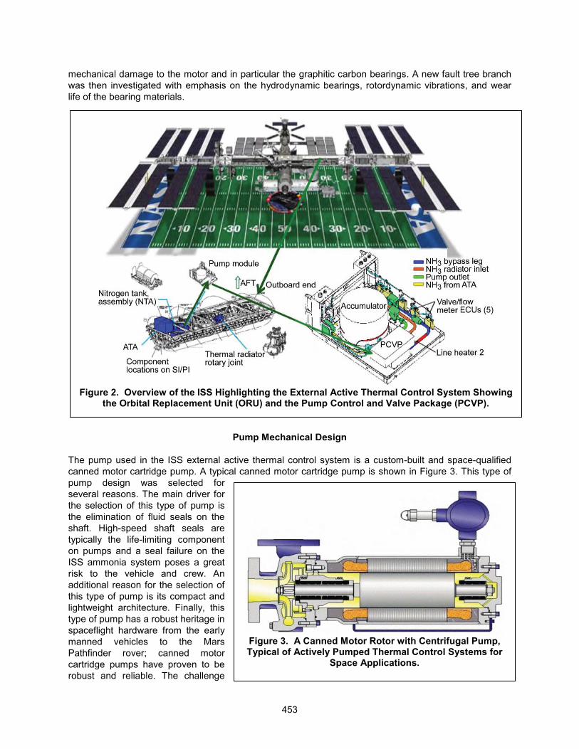
The pump used in the ISS external active thermal control system is a custom-built and space-qualified canned motor cartridge pump. A typical canned motor cartridge pump is shown in Figure 3. This type of pump design was selected for several reasons. The main driver for the selection of this type of pump is the elimination of fluid seals on the shaft. High-speed shaft seals are typically the life-limiting component on pumps and a seal failure on the ISS ammonia system poses a great risk to the vehicle and crew. An additional reason for the selection of this type of pump is its compact and lightweight architecture. Finally, this type of pump has a robust heritage in spaceflight hardware from the early manned vehicles to the Mars Pathfinder rover; canned motor cartridge pumps have proven to be robust and reliable. The challenge
Figure 2. Overview of the ISS Highlighting the External Active Thermal Control System Showing the Orbital Replacement Unit (ORU) and the Pump Control and Valve Package (PCVP).
Figure 3. A Canned Motor Rotor with Centrifugal Pump, Typical of Actively Pumped Thermal Control Systems for
Space Applications.
453
faced by the pump designer is to increase the life of these pumps as space missions become morechallenging. The operating life requirements for micro-gravity operation of high-speed centrifugal pumps has increased from days, to weeks, to years with the expectation of extending pump life to decades. The pump module failure of 2010 has provided invaluable experience in damage initiation and the progression of very light wear accumulation over a long period of time.
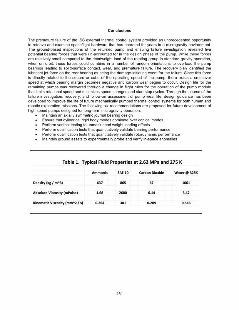
The main complication of this type of pump is the dual use of the working fluid as the hydrodynamic bearing lubricant. Characteristics of good heat transfer fluids and good lubricants are not complimentary.For high heat capacity at modest temperatures and low pressure drops through pumped loops, heat transfer fluids required high fluid density and low absolute viscosity. However, hydrodynamic bearings perform best with fluids having a low density and high absolute viscosity. For reference, typical fluid properties for anhydrous ammonia, SAE10 lubricating oil, and Carbon Dioxide gas are shown in Table 1.The technical challenge of using the process fluid as the hydrodynamic bearing lubricant often leads to a low bearing load capacity, low vibrational damping characteristics, and wear in the bearings. This bearing wear then becomes the primary life limiting factor for the pump. The canned motor type of pump is ubiquitous in terrestrial operations especially in applications where explosive, corrosive, and caustic liquids are processed such as petroleum refineries and chemical plants. In such ground-based applications, additional instrumentation is utilized to monitor machine health, rotor vibrations, and bearing wear, which permits maintenance intervals to be scheduled accordingly. However, for operation on spacecraft additional instrumentation and frequent maintenance intervals are not a reasonable solution.Therefore, design details that impact the wear life must be considered as important design parameters and qualification tests must be conducted to flesh out these details prior to mission launch.
The bearings used to support the rotor in this pump were rigid, hydrodynamic bearings. Two journal bearings supported the rotor in the radial direction, while a single sided thrust bearing positioned the rotor axially. A thrust washer was used to limit the axial rotor motion in the negative thrust direction, but in normal use the single sided thrust bearing was biased against the impeller inlet suction. During low speed operation and on startup and shutdown the thrust bearing was loaded by a skewed magnetic force generated by the electric rotor. The rotor-bearing system was a rigid shaft design with the permanent magnet motor straddle mounted between the journal bearings and the pump impeller was cantilevered.The journal bearings were 9 mm and 18 mm in diameter on the rear and front bearing respectively and separated axially by 144 mm. The clearance ratio of the journal bearings was 0.26% for both bearings.This created a static angular misalignment at zero speed of 79 microradians. The stationary sleeves of the bearing were fabricated from a special ammonia tolerant grade of graphitic carbon for low startup friction and low wear during solid surface contact events. Each bearing sleeve had four axial grooves machined at roughly equal spacing around the circumference to reduce the probability of half frequency whirl, impede the onset of turbulent flow, and to provide additional area for the secondary flow. Asecondary flowpath from the pump discharge provides lubricant flow to both journal bearings and the thrust bearing. The secondary flow also passed between the rotor-stator gap to provide cooling for the eddy current losses. The typical operating speed range of the pump is 11,000 to 14,700 revolutions per minute.
Hydrodynamic Bearing Performance
The hydrodynamic performance of the journal bearings is challenged in terms of fluidic instabilities and turbulence due to the relatively large clearances, high rotor speed, and low absolute viscosity of the lubricant. Figure 4 demonstrated this feature by overlaying the Taylor number region for the two journal bearings of the pump on top of experimental data taken for journal bearings operating with lubricants having very low kinematic viscosity. The data shown in Figure 4 used various high pressure gases as the lubricant in a concentric cylinder type of journal bearing. Despite the challenging conditions for the journal bearings, they are still able to generate meaningful film pressures and load support. The main reason that these bearings do not lose all film pressure to turbulence is the four axial grooves machined into the carbon sleeves. These grooves serve to reduce the turbulent length scale and maintain load support across each sector of the bearing. In order to calculate hydrodynamic load capacity for any journal
454
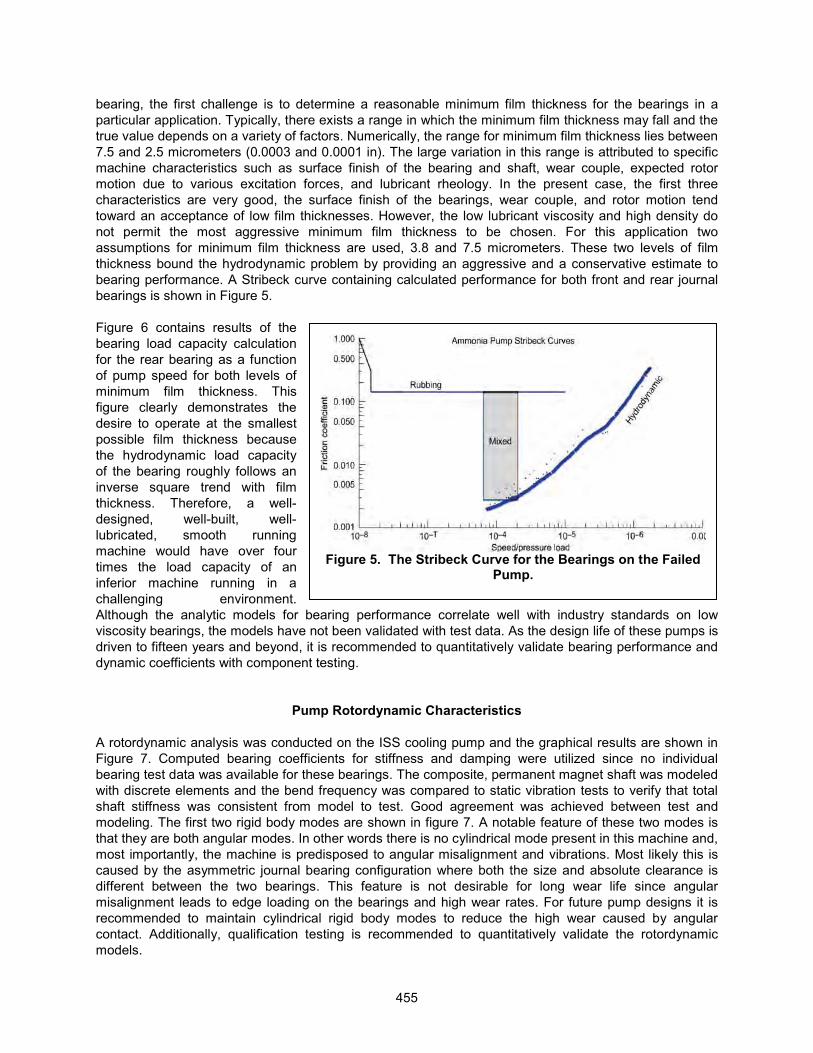
Figure 5. The Stribeck Curve for the Bearings on the Failed Pump.
bearing, the first challenge is to determine a reasonable minimum film thickness for the bearings in a particular application. Typically, there exists a range in which the minimum film thickness may fall and the true value depends on a variety of factors. Numerically, the range for minimum film thickness lies between 7.5 and 2.5 micrometers (0.0003 and 0.0001 in). The large variation in this range is attributed to specific machine characteristics such as surface finish of the bearing and shaft, wear couple, expected rotor motion due to various excitation forces, and lubricant rheology. In the present case, the first three characteristics are very good, the surface finish of the bearings, wear couple, and rotor motion tend toward an acceptance of low film thicknesses. However, the low lubricant viscosity and high density do not permit the most aggressive minimum film thickness to be chosen. For this application two assumptions for minimum film thickness are used, 3.8 and 7.5 micrometers. These two levels of film thickness bound the hydrodynamic problem by providing an aggressive and a conservative estimate to bearing performance. A Stribeck curve containing calculated performance for both front and rear journal bearings is shown in Figure 5.
Figure 6 contains results of the bearing load capacity calculation for the rear bearing as a function of pump speed for both levels of minimum film thickness. This figure clearly demonstrates the desire to operate at the smallest possible film thickness because the hydrodynamic load capacity of the bearing roughly follows an inverse square trend with film thickness. Therefore, a well-designed, well-built, well-lubricated, smooth running machine would have over four times the load capacity of an inferior machine running in a challenging environment. Although the analytic models for bearing performance correlate well with industry standards on low viscosity bearings, the models have not been validated with test data. As the design life of these pumps is driven to fifteen years and beyond, it is recommended to quantitatively validate bearing performance and dynamic coefficients with component testing.
Pump Rotordynamic Characteristics
A rotordynamic analysis was conducted on the ISS cooling pump and the graphical results are shown in Figure 7. Computed bearing coefficients for stiffness and damping were utilized since no individual bearing test data was available for these bearings. The composite, permanent magnet shaft was modeledwith discrete elements and the bend frequency was compared to static vibration tests to verify that total shaft stiffness was consistent from model to test. Good agreement was achieved between test and modeling. The first two rigid body modes are shown in figure 7. A notable feature of these two modes is that they are both angular modes. In other words there is no cylindrical mode present in this machine and, most importantly, the machine is predisposed to angular misalignment and vibrations. Most likely this is caused by the asymmetric journal bearing configuration where both the size and absolute clearance is different between the two bearings. This feature is not desirable for long wear life since angular misalignment leads to edge loading on the bearings and high wear rates. For future pump designs it is recommended to maintain cylindrical rigid body modes to reduce the high wear caused by angular contact. Additionally, qualification testing is recommended to quantitatively validate the rotordynamicmodels.
455
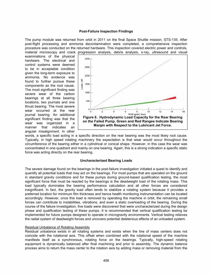
Figure 6. Hydrodynamic Load Capacity for the Rear Bearing on the Failed Pump. Green and Red Ranges Indicate Bearing
Margin with Respect to the Lubricant Jet Force.
Post-Failure Inspection Findings
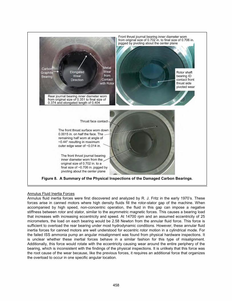
The pump module was returned from orbit in 2011 on the final Space Shuttle mission, STS-135. After post-flight processing and ammonia decontamination were completed, a comprehensive inspection procedure was conducted on the returned hardware. This inspection covered electric power and controls,material microscopy and crack progression analysis, debris analysis, x-ray, ultrasound and visual examinations of the physical hardware. The electrical and control systems were deemed to be in acceptable condition given the long-term exposure to ammonia. No evidence was found to further pursue these components as the root cause.The most significant finding was severe wear of the carbon bearings at all three bearing locations, two journals and one thrust bearing. The most severe wear occurred at the rear journal bearing. An additional significant finding was that the wear was organized in a manner that indicates an angular misalignment. In other words, a specific load acting in a specific direction on the rear bearing was the most likely root cause.Typically, in high speed rotating machinery the expectation is that wear would occur throughout the circumference of the bearing either in a cylindrical or conical shape. However, in this case the wear was concentrated in one quadrant and mainly on one bearing. Again, this is a strong indication a specific static force was acting directly on the rear bearing.
Uncharacterized Bearing Loads
The severe damage found on the bearings in the post-failure investigation initiated a quest to identify and quantify all potential loads that may act on the bearings. For most pumps that are operated on the ground in standard gravity conditions and for these pumps during ground-based qualification testing, the most significant force that must be reacted by the bearings is the deadweight load of the rotating mass. This load typically dominates the bearing performance calculation and all other forces are considered insignificant. In fact, the gravity load often tends to stabilize a rotating system because it provides a preferred location for minimum film thickness and hence health monitoring instrumentation can be located accordingly. However, once this load is removed by operating the machine in orbit, the remaining small forces can contribute to instabilities, vibrations, and even a static overloading of the bearing. During the course of the failure investigation, five loads were discovered that were uncharacterized during the design phase and qualification testing of these pumps. It is recommended that vertical qualification testing beimplemented for future pumps designed to operate in microgravity environments. Vertical testing relieves the radial system of deadweight forces and uncovers potential deleterious effects of an unloaded system.
Residual Unbalance of Rotating AssemblyResidual unbalance exists in all rotating systems and exists when the line of mass centers does not coincide with the rotational axis. This offset when combined with the rotational speed of the machine manifests itself as a synchronous, rotating force on the bearings. Typically, high-speed rotating equipment is dynamically balanced after final machining and prior to assembly. The dynamic balance process aims to return the mass center to the rotation axis by adding mass or removing material from the
456
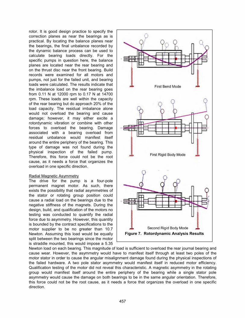
Figure 7. Rotordynamic Analysis Results
rotor. It is good design practice to specify the correction planes as near the bearings as is practical. By locating the balance planes near the bearings, the final unbalance recorded by the dynamic balance process can be used to calculate bearing loads directly. For the specific pumps in question here, the balance planes are located near the rear bearing and on the thrust disc near the front bearing. Build records were examined for all motors and pumps, not just for the failed unit, and bearing loads were calculated. The results indicate that the imbalance load on the rear bearing goes from 0.11 N at 12000 rpm to 0.17 N at 14700 rpm. These loads are well within the capacity of the rear bearing but do approach 20% of the load capacity. The residual imbalance alone would not overload the bearing and cause damage; however, it may either excite arotordynamic vibration or combine with other forces to overload the bearing. Damage associated with a bearing overload from residual unbalance would manifest itself around the entire periphery of the bearing. This type of damage was not found during the physical inspection of the failed pump.Therefore, this force could not be the root cause, as it needs a force that organizes theoverload in one specific direction.
Radial Magnetic AsymmetryThe drive for the pump is a four-pole permanent magnet motor. As such, there exists the possibility that radial asymmetries of the stator or rotating group position could cause a radial load on the bearings due to the negative stiffness of the magnets. During the design, build, and qualification of the motors no testing was conducted to quantify the radial force due to asymmetry. However, this quantity is bounded by the contract specifications to the motor supplier to be no greater than 10.7 Newton. Assuming this load would be equallysplit between the two bearings since the motor is straddle mounted, this would impose a 5.35 Newton load on each bearing. This magnitude of load is sufficient to overload the rear journal bearing and cause wear. However, the asymmetry would have to manifest itself through at least two poles of the motor stator in order to cause the angular misalignment damage found during the physical inspections of the failed hardware. A two pole stator asymmetry would manifest itself in reduced motor efficiency.Qualification testing of the motor did not reveal this characteristic. A magnetic asymmetry in the rotating group would manifest itself around the entire periphery of the bearing while a single stator pole asymmetry would cause the damage on both bearings to be in the same angular orientation. Therefore, this force could not be the root cause, as it needs a force that organizes the overload in one specific direction.
457
Annulus Fluid Inertia ForcesAnnulus fluid inertia forces were first discovered and analyzed by R. J. Fritz in the early 1970’s. These forces arise in canned motors where high density fluids fill the rotor-stator gap of the machine. When accompanied by high speed, non-concentric operation, the fluid in this gap can impose a negative stiffness between rotor and stator, similar to the asymmetric magnetic forces. This causes a bearing load that increases with increasing eccentricity and speed. At 14700 rpm and an assumed eccentricity of 25 micrometers, the load on each bearing would be 2.58 Newton from the annular fluid force. This force is sufficient to overload the rear bearing under most hydrodynamic conditions. However, these annular fluid inertia forces for canned motors are well understood for eccentric rotor motion in a cylindrical mode. For the failed ISS ammonia pump an angular misalignment was found from physical hardware inspections. Itis unclear whether these inertial forces behave in a similar fashion for this type of misalignment.Additionally, this force would rotate with the eccentricity causing wear around the entire periphery of the bearing, which is inconsistent with the findings of the physical inspections. It is unlikely that this force was the root cause of the wear because, like the previous forces, it requires an additional force that organizes the overload to occur in one specific angular location.
Figure 8. A Summary of the Physical Inspections of the Damaged Carbon Bearings.
458
Load Alignment with Respect to Bearing PadBoth the front and the rear journal bearings used in this pump utilize axial grooves machined into the carbon sleeves. These grooves serve to disrupt the half frequency whirl flow pattern and delay the transition to turbulence in the fluid film. A detriment to bearing performance caused by this feature is to weaken the load capacity of the bearing when the load is oriented on or near one of these grooves. This orientation can reduce bearing load capacity by 55% compared with an orientation where the load is well-centered on the pad. During the assembly procedures of the pumps, no control measures were put in place to dictate the orientation of these grooves. Therefore this is a truly random variable, which may or may not become significant depending also on the orientation of the additional imposed loads. Physical inspections of the failed hardware revealed that the rear bearing wear was concentrated at one of these axial grooves. In fact, the wear was so severe that the 1.5-mm-deep groove was no longer a visible feature and the wear had gone deeper than the bottom of the groove. The evidence strongly implies that the orientation of the load on a groove is a major contributing factor to the failure of the ammonia pump.However, the load orientation only serves to diminish the load capacity, a force acting in this specific direction must be present to overload the bearing and cause the damage.
Lubricant Jet Force on Rear BearingA unique feature of the secondary flowpath on the failed ISS ammonia pump was the single lubricant feed supply hole to the rear bearing. In addition to having just one supply hole to the rear bearing the lubricant was directed radially toward the shaft extension aft of the bearing. This is in contrast to the notional pump shown in Figure 3. Examination of the right side of this figure shows that the lubricant to the rear bearing is canted toward the rear endplate of the motor, not toward the shaft, and that there are symmetric supply holes to the rear bearing. This design practice ensures that no net force is imposed on the rear bearing due to the lubricant supply and secondary flowpath of the motor. However, the design that was implemented on the failed ammonia pump permitted a radial load to be imposed on the rear bearing due to the jet force of the lubricant feed. An analysis was conducted on the magnitude of this force as a function of pump rotational speed. The results of this analysis are cross-plotted on Figure 6 and show that this force can overload the 7.5 micrometer load capacity limit of the bearing at 12500 rpm. Furthermore,the finding of the physical inspections revealed that the wear on the rear bearing was in the direct opposite direction from the lubricant feed hole. There are two strong indications that the lubricant jet force on the rear bearing was the root cause of the bearing failure and initiated the damage to the rear bearing carbon. First, the load margin analysis showed that the jet force alone could overload the rear bearing at 12500 rpm without considering the additional effects of the previous four factors providing additional bearing loads or reduced capacity. Second, the wear pattern was consistent with a uni-directional load causing a static angular misalignment, which is the expected manifestation of the single jet force aft of the rear bearing.
Recovery and Modified Operations
The tactical recovery for the ISS from the 2010 ammonia pump failure was the replacement of the pump ORU with a functional on-orbit spare. Three EVAs were used to accomplish this task. Full function and operation of the ISS was restored by this activity. The strategic recovery focused on restoring the full 15-year operational life of the pump module and ensuring that the ISS had a full complement of spares available to complete its projected life. In order to accomplish the strategic objective, additional questions needed to be answered and the root cause of the failure needed to be verified. Of primary importance was the determination that the failed pump was an ‘in family’ pump and no extenuating factors impacted the reduced life of the pump. A comprehensive review was conducted on all of the build records and qualification tests. No information was uncovered that would suggest that the failed pump had a unique history that would predispose it to premature failure. This finding placed an emphasis on the verification of the root cause and potential modifications to the operating procedures to restore pump life for future modules. The lack of a ground asset that could be instrumented to validate a root cause scenario limited the ability of the team to conduct comprehensive validation testing. A recommendation for future system development is to maintain ground assets such that in-space anomalies can readily be investigated.
459
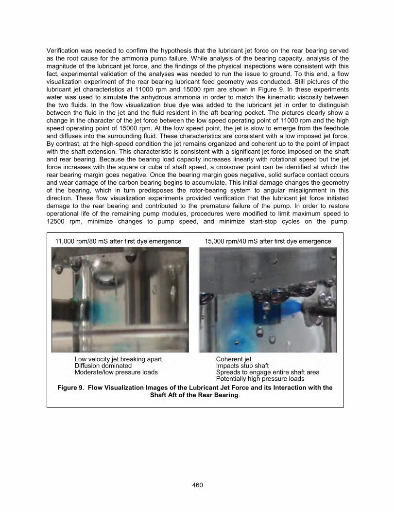
Verification was needed to confirm the hypothesis that the lubricant jet force on the rear bearing served as the root cause for the ammonia pump failure. While analysis of the bearing capacity, analysis of the magnitude of the lubricant jet force, and the findings of the physical inspections were consistent with this fact, experimental validation of the analyses was needed to run the issue to ground. To this end, a flow visualization experiment of the rear bearing lubricant feed geometry was conducted. Still pictures of the lubricant jet characteristics at 11000 rpm and 15000 rpm are shown in Figure 9. In these experiments water was used to simulate the anhydrous ammonia in order to match the kinematic viscosity between the two fluids. In the flow visualization blue dye was added to the lubricant jet in order to distinguish between the fluid in the jet and the fluid resident in the aft bearing pocket. The pictures clearly show achange in the character of the jet force between the low speed operating point of 11000 rpm and the high speed operating point of 15000 rpm. At the low speed point, the jet is slow to emerge from the feedhole and diffuses into the surrounding fluid. These characteristics are consistent with a low imposed jet force.By contrast, at the high-speed condition the jet remains organized and coherent up to the point of impact with the shaft extension. This characteristic is consistent with a significant jet force imposed on the shaft and rear bearing. Because the bearing load capacity increases linearly with rotational speed but the jet force increases with the square or cube of shaft speed, a crossover point can be identified at which the rear bearing margin goes negative. Once the bearing margin goes negative, solid surface contact occurs and wear damage of the carbon bearing begins to accumulate. This initial damage changes the geometry of the bearing, which in turn predisposes the rotor-bearing system to angular misalignment in this direction. These flow visualization experiments provided verification that the lubricant jet force initiated damage to the rear bearing and contributed to the premature failure of the pump. In order to restore operational life of the remaining pump modules, procedures were modified to limit maximum speed to 12500 rpm, minimize changes to pump speed, and minimize start-stop cycles on the pump.
Figure 9. Flow Visualization Images of the Lubricant Jet Force and its Interaction with the Shaft Aft of the Rear Bearing.
460
Conclusions
The premature failure of the ISS external thermal control system provided an unprecedented opportunityto retrieve and examine spaceflight hardware that has operated for years in a microgravity environment.The ground-based inspections of the returned pump and ensuing failure investigation revealed fivepotential bearing forces that were un-accounted for in the design phase of the pump. While these forces are relatively small compared to the deadweight load of the rotating group in standard gravity operation, when on orbit, these forces could combine in a number of random orientations to overload the pump bearings leading to solid-surface contact, wear, and premature failure. The recovery plan identified the lubricant jet force on the rear bearing as being the damage-initiating event for the failure. Since this force is directly related to the square or cube of the operating speed of the pump, there exists a crossover speed at which bearing margin becomes negative and carbon wear begins to occur. Design life for the remaining pumps was recovered through a change in flight rules for the operation of the pump modulethat limits rotational speed and minimizes speed changes and start stop cycles. Through the course of the failure investigation, recovery, and follow-on assessment of pump wear life, design guidance has been developed to improve the life of future mechanically pumped thermal control systems for both human and robotic exploration missions. The following six recommendations are proposed for future development of high speed pumps designed for long-term microgravity operation:
� Maintain an axially symmetric journal bearing design� Ensure that cylindrical rigid body modes dominate over conical modes� Perform vertical testing to unmask dead weight loading effects� Perform qualification tests that quantitatively validate bearing performance� Perform qualification tests that quantitatively validate rotordynamic performance� Maintain ground assets to experimentally probe and verify in-space anomalies
461
References
1. Active Thermal Control System (ATCS) Overview, The Boeing Company, http://www.boeing.com/assets/pdf/defense-space/space/spacestation/systems/docs/ISS%20Active%20Thermal%20Control%20System.pdf
2. Birur, G.C., Bhandari, P., Gram, M.B., Durkee, J., “Integrated Pump Assembly – An Active Cooling System for Mars Pathfinder Thermal Control”, Society of Automotive Engineers, 26th International Conference on Environmental Sciences, Monterey, CA, 1996
3. Bloch, P.E., “Understanding Canned Motor Pumps”, Maintenance Technology, 01 September 2008.4. Duchesne, S.M., Sweterlitsch, J. J., Son, C. H., Perry, J. L., “Impacts of an Ammonia Leak on the
Cabin Atmosphere of the International Space Station”, American Institute of Aeronautics and Astronautics, International Conference on Environmental Systems (ICES); San Diego, CA; 15-19 Jul. 2012; United States, 2012.
5. Lockwood, M.K., Ercol, C.J., Cho, W.L., Hartman, D., Adamson, G., “An Active Cooling System for the Solar Probe Power System”, American Institute of Aeronautics and Astronautics, International Conference on Environmental Systems, AIAA-2010-6294, 2010.
6. Ticker, R., “Engineering Test Beds on the International Space Station”, IEEE A&E Systems Magazine, August 2009.
7. Swanson, T.D., Birur, G. C., “NASA Thermal Control Technologies for Robotic Spacecraft”, National Aeronautics and Space Administration, N20030031332, 2003.
8. Westheimer, D. T., Tuan, G. C., “Active Thermal Control System Considerations for the Next Generation of Human Rated Space Vehicles”, American Institute of Aeronautics and Astronautics AeroSpace Sciences Meeting, AIAA-2005-342, 2005.
9. Paris, A.D., Bhandari, P., Birur, G.C., “High Temperature Mechanically Pumped Fluid Loop for Space Applications – Working Fluid Selection”, SAE International, 04ICES-282, 2004.
10. Jimenez, A.P., Hoberecht, M.A., “ Space Station Freedom Photovoltaic Power Module Design Status”, National Aeronautics and Space Administration, 899271, IEEE , 1989.
11. Shen, F., Drolen, B., Prabhu, J., Harper, L., Eichinger, E., Hgyuen, C., “Long Life Mechanical Fluid Pump for Space Applications”, American Institute of Aeronautics and Astronautics AeroSpace Sciences Meeting, AIAA-2005-273, 2005.
12. Son, C.H., “ Numerical Study of Ammonia Leak and Dispersion in the International Space Station”, American Institute of Aeronautics and Astronautics, International Conference on Environmental Systems (ICES); San Diego, CA; 15-19 Jul. 2012; United States, 2012
13. Baldauf R. W., Kawecki, T., Purdy, W., Hoang, T.T., “Development of a Bearingsless Ammonia Pump for Spacecraft Thermal Control”, NRL Review, 2008
14. Midgley, J.W., Teer, D. G., “An Investigation of the Mechanism of the Friction and Wear of Carbon”, Transactions of the ASME, American Society of Mechanical Engineers, December, 1963.
15. Fritz, R.J., “The Effects of an Annular Fluid on the Vibrations of a Long Rotor, Part 1 – Theory”, Journal of basic Engineering, December 1970.
16. Fritz, R.J., “The Effects of an Annular Fluid on the Vibrations of a Long Rotor, Part 2 – Test”, Journal of basic Engineering, December 1970.
462