Embed Size (px)
Citation preview
ISW-EN4200 Serial Receiver Installation Guide
Overview The Bosch Commercial Wireless ISW-EN4200 Serial Receiver, powered by Inovonics wireless mesh network technology, connects Commercial Wireless Sensors to supported Bosch control panels via the ISW-D8125CW-V2 Interface Module. These instructions cover installation of the ISW-EN4200 Serial Receiver. For detailed programming instructions, refer to the ISW-D8125CW-V2 Installation and Operation Guide (P/N: F01U161691).
1.0 Installation Use the provided anchors and screws to mount the ISW-EN4200 in locations accessible for future maintenance. For best transmitter reception results, place the ISW-EN4200 in a central location among the transmitters. If transmitters are too far away for the receiver to pick up the transmission, install an ISW-EN5040-T Commercial Wireless RF Repeater.
For UL Listed installations, install the ISW-D8125CW-V2 Commercial Wireless Interface Module within 20 ft (6 m) of, and within the same room as, the ISW-EN4200.
Mount the serial receiver in a location removed from metal. Metal objects (duct work, wire mesh screens, boxes) reduce RF range.
2.0 Configuration Bosch Commercial Wireless products use a range of radio frequencies and must be configured for your geographic area. All selection jumpers are shipped in their default positions (Figure 1). If you want to keep the default selections, setting the jumpers is not necessary. The ISW-EN4200 ships configured for North America frequencies.
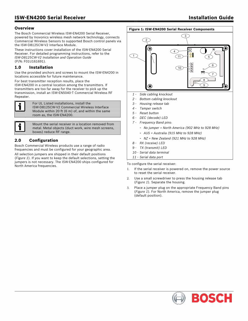
Figure 1: ISW-EN4200 Serial Receiver Components
������
��
����
�� ���
��
����
��������
�
�
�
�
�
�
�
�
1 - Side cabling knockout 2 - Bottom cabling knockout 3 - Housing release tab 4 - Tamper switch 5 - Reset button 6 - DEC (decode) LED 7 - Frequency Band pins:
- No jumper = North America (902 MHz to 928 MHz)
- AUS = Australia (915 MHz to 928 MHz)
- NZ = New Zealand (921 MHz to 928 MHz) 8 - RX (receive) LED 9 - TX (transmit) LED 10 - Serial data terminal 11 - Serial data port
T
To configure the serial receiver:
1. If the serial receiver is powered on, remove the power source to reset the serial receiver.
2. Use a small screwdriver to press the housing release tab (Figure 1). Separate the housing.
3. Place a jumper plug on the appropriate Frequency Band pins (Figure 1). For North America, remove the jumper plug (default position).
2 | F01U167054-01 | 8/10 ISW-EN4200 Serial Receiver Installation Guide © 2010 Bosch Security Systems, Inc.
3.0 Wiring Connections
Do not install long cable runs next to high-current power feeds. Keep cable lengths as short as possible to minimize noise pickup. Measure voltage at the serial receiver on long cable runs.
To connect the ISW-EN4200 to the ISW-D8125CW-V2:
1. Remove all power from the system (AC and standby battery).
2. Route the cabling through either the bottom cabling knockout or the side cabling knockout on the ISW-EN4200. Refer to Figure 1.
3. Connect the serial data terminal block on the ISW-EN4200 to the data terminal block on the ISW-D8125CW-V2. Refer to Figure 2 below, or Figure 3 on page 3.
Ensure that the wiring used meets the following specifications:
- Four-conductor unshielded 20 AWG (or larger)
- Wire length must not exceed 30.5 m (100 ft) For UL Listed installations, install the ISW-D8125CW-V2 Commercial Wireless Interface Module within 20 ft (6 m) of, and within the same room as, the ISW-EN4200.
4. Connect the ISW-D8125CW-V2 to the control panel.
- For all versions of the D7412 and D7212 Control Panels, you can connect one ISW-D8125CW-V2 Commercial Wireless Interface Module, and up to two ISW-EN4200 Serial Receivers. Refer to Figure 2 below.
- For all versions of the D9412 Control Panel, and the D9112 Control Panel, you can connect two ISW-D8125CW-V2 Commercial Wireless Interface Modules (one to Zonex 1 and the other to Zonex 2), and up to four ISW-EN4200 Serial Receivers (two to each ISW-D8125CW-V2). Refer to Figure 3 on page 3.
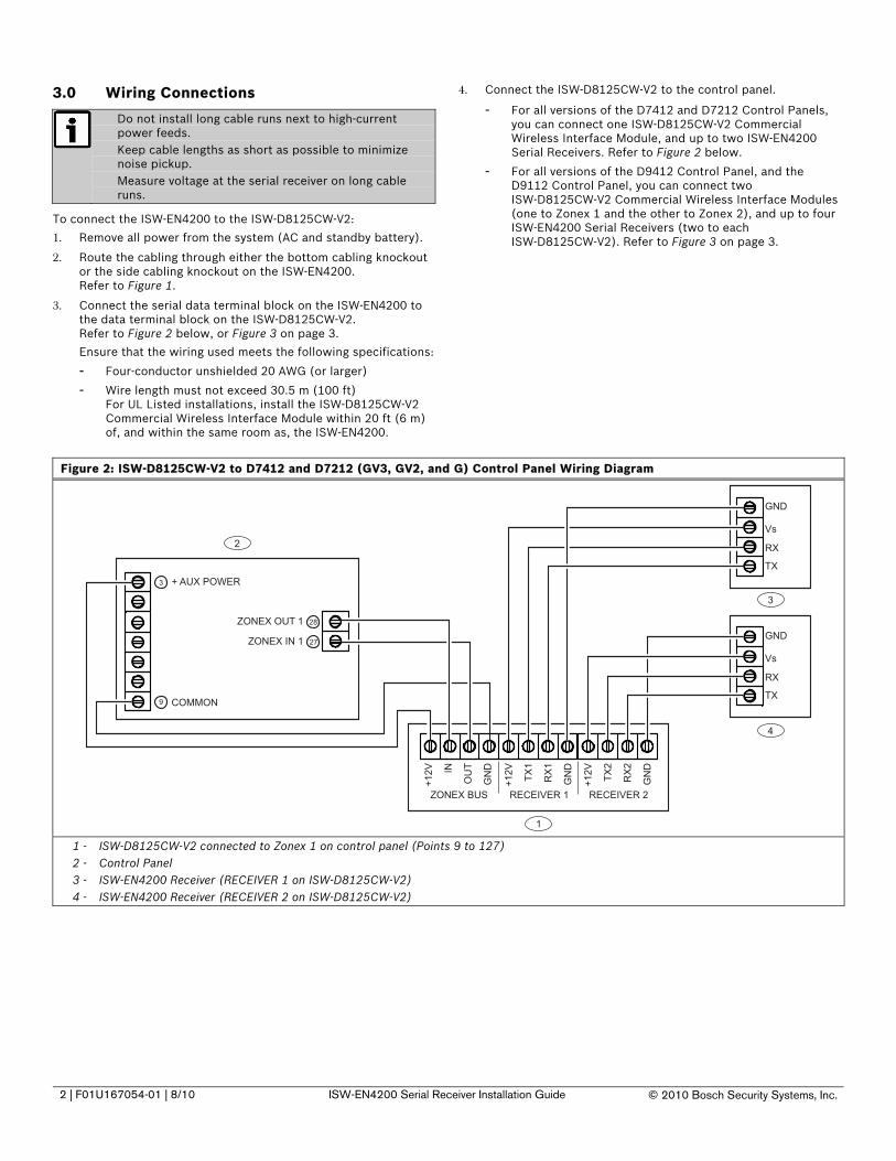
Figure 2: ISW-D8125CW-V2 to D7412 and D7212 (GV3, GV2, and G) Control Panel Wiring Diagram
��������� ���������������
���
��
�
���
��� ��
���
���
���
���
��
���
��
�
��
���
��
�
��
�������������
��������� ��
��
�
�
�������� �
��!!���
1 - ISW-D8125CW-V2 connected to Zonex 1 on control panel (Points 9 to 127) 2 - Control Panel 3 - ISW-EN4200 Receiver (RECEIVER 1 on ISW-D8125CW-V2) 4 - ISW-EN4200 Receiver (RECEIVER 2 on ISW-D8125CW-V2)
© 2010 Bosch Security Systems, Inc. ISW-EN4200 Serial Receiver Installation Guide 8/10 | F01U167054-01 | 3
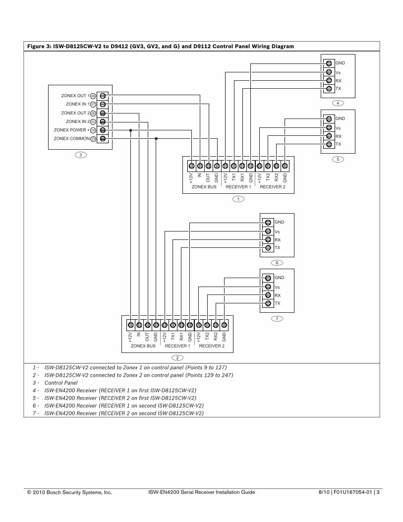
Figure 3: ISW-D8125CW-V2 to D9412 (GV3, GV2, and G) and D9112 Control Panel Wiring Diagram
�����������
����������
�������� ���
��������!!�� �
��
��
��
��
������������
���������
��������� ���������������
���
��
�
���
��� ��
���
���
���
���
��
���
��
�
��
���
��
�
��
���
��������� ���������������
���
��
�
���
��� ��
���
���
���
���
��
���
��
�
��
���
��
�
��
���
�
�
�
�
�
1 - ISW-D8125CW-V2 connected to Zonex 1 on control panel (Points 9 to 127) 2 - ISW-D8125CW-V2 connected to Zonex 2 on control panel (Points 129 to 247) 3 - Control Panel 4 - ISW-EN4200 Receiver (RECEIVER 1 on first ISW-D8125CW-V2) 5 - ISW-EN4200 Receiver (RECEIVER 2 on first ISW-D8125CW-V2) 6 - ISW-EN4200 Receiver (RECEIVER 1 on second ISW-D8125CW-V2) 7 - ISW-EN4200 Receiver (RECEIVER 2 on second ISW-D8125CW-V2)
Bosch Security Systems, Inc. 130 Perinton Parkway Fairport, NY 14450 USA www.boschsecurity.com © Bosch Security Systems, Inc., 2010
F01U167054-01 Installation Guide
8/10ISW-EN4200 Serial Receiver
Page 4 of 4
4.0 Register the RF Transmitters You must register all transmitters and repeaters with the ISW-D8125CW-V2. Bosch Commercial Wireless devices employ wireless registration, so there is no need to connect the transmitter to the ISW-D8125CW-V2. No data is written to the transmitter during registration. To register transmitters and repeaters (end devices):
1. Program the transmitter as described in the ISW-D8125CW-V2 Installation and Operation Guide (P/N: F01U161691).
2. When prompted by the ISW-D8125CW-V2, press the RESET button on the end device.
- Press the end device’s RESET button once if the ISW-D8125CW-V2 is set to accept registration after a single reset message
- Press the end device’s RESET button twice if the ISW-D8125CW-V2 is set for a double button push.
- Depending on which ISW-EN4200 Serial Receiver received the reset message, either the RX1 LED or the RX2 LED on the ISW-D8125CW-V2 lights when the first reset message is received.
- Depending on which ISW-EN4200 Serial Receiver received the reset message, either the RX1 LED or the RX2 LED on the ISW-D8125CW-V2 lights when the last reset message is received.
3. When the end device is successfully registered, the ISW-D8125CW-V2 shows “Programmed” on its keypad display.
4. From the control panel, perform a walk test to ensure all registered devices work as expected. To perform a walk test, refer to your control panel documentation.
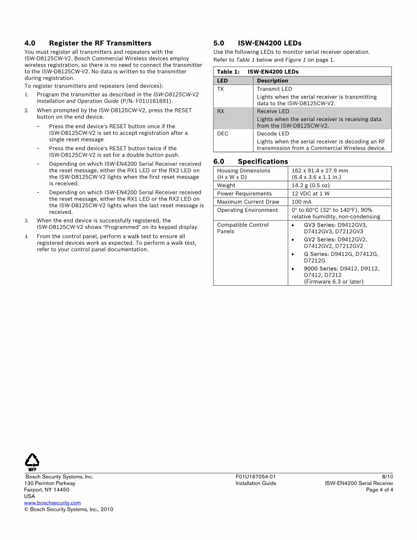
5.0 ISW-EN4200 LEDs Use the following LEDs to monitor serial receiver operation. Refer to Table 1 below and Figure 1 on page 1.
Table 1: ISW-EN4200 LEDs
LED Description TX Transmit LED
Lights when the serial receiver is transmitting data to the ISW-D8125CW-V2.
RX Receive LED Lights when the serial receiver is receiving data from the ISW-D8125CW-V2.
DEC Decode LED Lights when the serial receiver is decoding an RF transmission from a Commercial Wireless device.
6.0 Specifications Housing Dimensions (H x W x D)
162 x 91.4 x 27.9 mm (6.4 x 3.6 x 1.1 in.)
Weight 14.2 g (0.5 oz) Power Requirements 12 VDC at 1 W Maximum Current Draw 100 mA Operating Environment 0° to 60°C (32° to 140°F), 90%
relative humidity, non-condensing Compatible Control Panels
GV3 Series: D9412GV3, D7412GV3, D7212GV3
GV2 Series: D9412GV2, D7412GV2, D7212GV2
G Series: D9412G, D7412G, D7212G
9000 Series: D9412, D9112, D7412, D7212 (Firmware 6.3 or later)


![Wyzwania [ISW]](https://img.pdfslide.net/doc/110x75/547da46db379594e2b8b52cd/wyzwania-isw.jpg)