Embed Size (px)
DESCRIPTION
IT1 U11 - Fixings - Complete
Citation preview
CGLI 2330 Certificate in Electrotechnical Technology Level 2 Inst Tech: Unit 202 – Principles of Electrotechnology
Unit 11 – Fixings
The College at Clacton Unit 11 Page 1 January 2012
Fixings
Unit Aims
By the end of the unit participants should be able to:
Identify fitting/fixing activities a) isolation procedures b) check specifications c) determine appropriate fixing/fitting methods
Syllabus Reference: 2.4.06
Fixings
Isolation Procedures
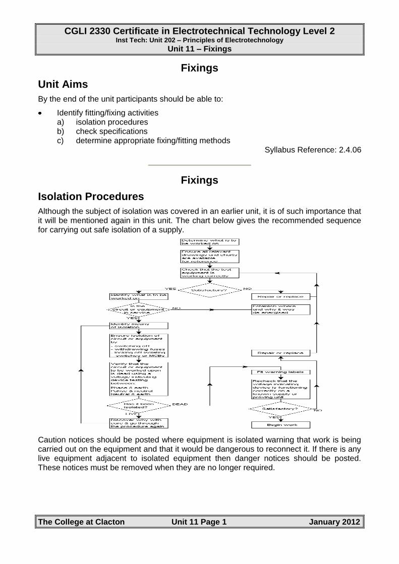
Although the subject of isolation was covered in an earlier unit, it is of such importance that it will be mentioned again in this unit. The chart below gives the recommended sequence for carrying out safe isolation of a supply.
Caution notices should be posted where equipment is isolated warning that work is being carried out on the equipment and that it would be dangerous to reconnect it. If there is any live equipment adjacent to isolated equipment then danger notices should be posted. These notices must be removed when they are no longer required.
CGLI 2330 Certificate in Electrotechnical Technology Level 2 Inst Tech: Unit 202 – Principles of Electrotechnology
Unit 11 – Fixings
The College at Clacton Unit 11 Page 2 January 2012
Checking Specifications
When carrying out any electrical installation work it is important to ensure that the customer’s requirements are met in their entirety. On all but small installations these requirements will normally be contained in a formal ‘specification’. The specification will detail information, along with plans and pictures of all aspects of the working in hand including:
Building construction
Electrical installation electricity supply
Wiring
Mounting heights
Circuit protection
Details of accessories to be installed
It is most important that the specification is interpreted and applied correctly if the customer is to be satisfied with the finished job. The following pages give an example specification for a fictitious commercial electrical installation.
CT Manufacturing Ltd.
Specification
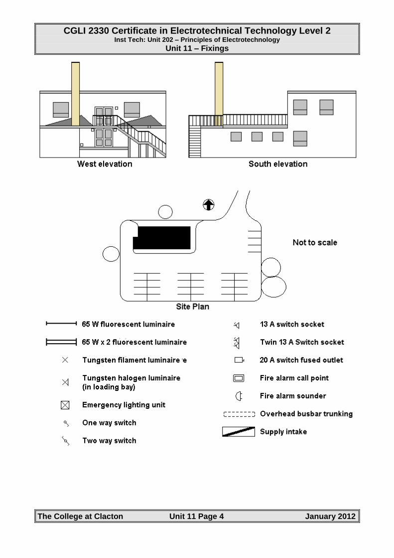
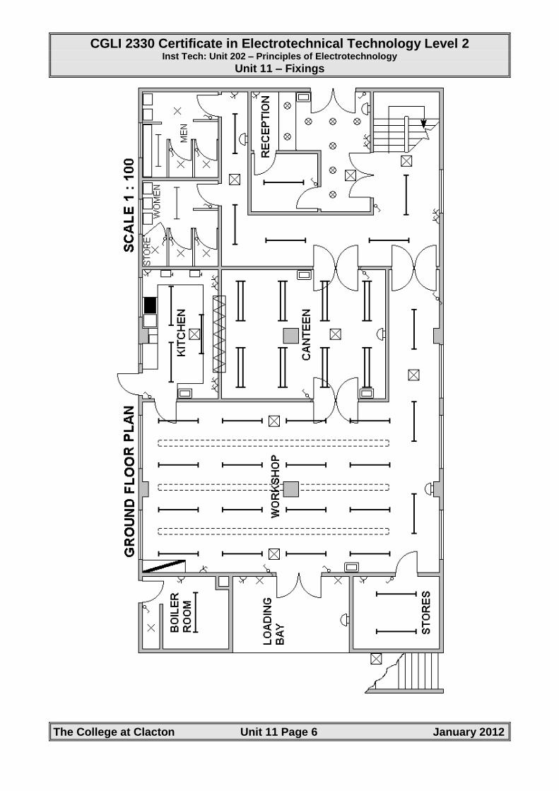
The drawings show a factory which manufactures small electrical products.
Building construction
The building is of steel frame construction with facing bricks externally and an inner skin of lightweight concrete blocks. The roof over the workshop area and half of the canteen is a double pitched roof supported by steel roof trusses having lattice girders which, in turn, are supported by stanchions positioned as shown in the drawings. The roof is of corrugated sheets with lights fitted over the workshop area. The valley between the double pitch acts as a fire escape from the first floor offices.
The height from the finished floor level to the underside of the horizontal joists is 4.0m.
The floor is a cast-in-situ concrete slab with screed finish. The first floor only covers half of the ground floor area. The roof to this is cast-in-situ concrete slabs covered with standard bitumen to the required thickness.
Electrical installation
The electrical installation is in accordance with the Electricity at Work Regulations 1989 and BS 7671:1992 Requirements for Electrical Installations.
Electricity supply
The supply is three-phase four wire 400/230V 50Hz.
The supply and installation form a TN-C-S system protected in the supply company's cut out by 3 x 100A BS EN 60269-1:1994 (BS88 Part 2 and Part 6) type fuses.
Ze is 0.3Ω and Ipf is 16kA.
CGLI 2330 Certificate in Electrotechnical Technology Level 2 Inst Tech: Unit 202 – Principles of Electrotechnology
Unit 11 – Fixings
The College at Clacton Unit 11 Page 3 January 2012
Wiring
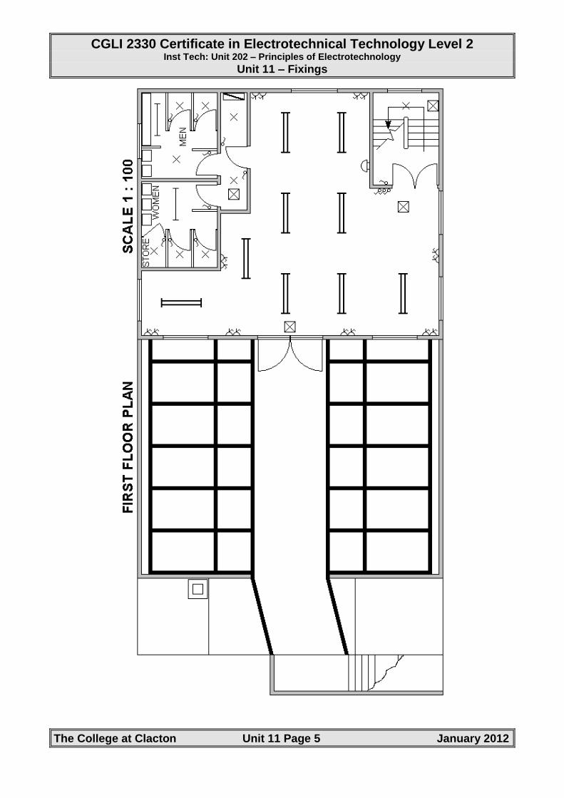
The submain between the two distribution boards is a 35mm2 two-core XLPE/SWA/LSF cable with copper conductors which is 28 metres long, run cleated to a perforated steel cable tray and no factors apply. Circuits supplied from the first floor distribution board must not exceed 3.5 volts drop. Measured from the first floor distribution board Zdb is 0.8242Ω and Is is 5.4kA. The submain is protected by a 63A BS EN 60269-1:1994 (BS88 Part 2 and Part 6) type fuse. Power supplies to the main workshop area are taken from an overhead busbar trunking as shown.
Lighting to the ground floor is by PVC insulated single core cables with copper conductors installed in heavy gauge B.E. steel conduit. Ground floor power is via a steel trunking and conduit system using PVC insulated single cables with copper conductors.
First floor circuits are installed in heavy gauge PVC conduit using single core PVC insulated single cables with copper conductors.
Where steel conduit or trunking is used it forms the only cpc for the circuitry.
The power to the boiler room and the whole of the fire alarm system are installed in mims cable with copper conductors and sheath. The cable is served overall with PVC insulation and installed on steel cable tray.
Emergency lighting units are self contained, non-maintained and supplied normally from the appropriate lighting circuit to keep their batteries charged. For the calculation of circuit loads these may be ignored.
Mounting heights for electrical equipment
From F.F.L. to centre
Socket outlets 1 m
Light switches 1.15 m
Kitchen equipment 1 m
Distribution boards ground floor 3 m
first floor 1.8 m
(ceiling height 2.4 m)
Circuit protection
With the exception of the first floor circuits HBC fuses to BS EN 60269-1:1994 are used throughout. Each of the first floor circuits is protected by a Type C CB to BS EN 60898.
CGLI 2330 Certificate in Electrotechnical Technology Level 2 Inst Tech: Unit 202 – Principles of Electrotechnology
Unit 11 – Fixings
The College at Clacton Unit 11 Page 4 January 2012
CGLI 2330 Certificate in Electrotechnical Technology Level 2 Inst Tech: Unit 202 – Principles of Electrotechnology
Unit 11 – Fixings
The College at Clacton Unit 11 Page 5 January 2012
CGLI 2330 Certificate in Electrotechnical Technology Level 2 Inst Tech: Unit 202 – Principles of Electrotechnology
Unit 11 – Fixings
The College at Clacton Unit 11 Page 6 January 2012
CGLI 2330 Certificate in Electrotechnical Technology Level 2 Inst Tech: Unit 202 – Principles of Electrotechnology
Unit 11 – Fixings
The College at Clacton Unit 11 Page 7 January 2012
Fixing Techniques
Fixing Tools
There are many different types of fixing tool. With the exception of the cartridge hammer gun and cable stapler, all the tools listed below are a powered version of their hand-tool equivalent.
Timber nail gun
Electric impact wrench
Cable stapler
Cartridge hammer gun
Cordless riveter
Cordless screwdriver
Cordless drill
Safety awareness
Cartridge guns and compressed airlines are examples of particularly dangerous tools and equipment and should never be abused.
Fixings
The electrical industry uses a large variety of fixing and fastening methods and there can be confusion over terminology. This section looks at the various types of fixings and fastenings and where they are used.
Screws and Bolts
Wood Screws
These are usually used when fixing items to wood. In the electrical industry they are more commonly used in conjunction with rawl plugs where fastenings to masonry are required. When ordering wood screws it is important to give the correct description, including four key pieces of information:
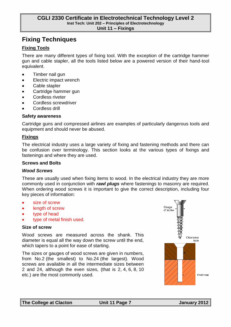
size of screw
length of screw
type of head
type of metal finish used.
Size of screw
Wood screws are measured across the shank. This diameter is equal all the way down the screw until the end, which tapers to a point for ease of starting.
The sizes or gauges of wood screws are given in numbers, from No.2 (the smallest) to No.24 (the largest). Wood screws are available in all the intermediate sizes between 2 and 24, although the even sizes, (that is 2, 4, 6, 8, 10 etc.) are the most commonly used.
CGLI 2330 Certificate in Electrotechnical Technology Level 2 Inst Tech: Unit 202 – Principles of Electrotechnology
Unit 11 – Fixings
The College at Clacton Unit 11 Page 8 January 2012
In the electrical field, sizes 6, 8 and 10 are usually used for cable fixing and for mounting boxes and accessories. Larger sizes may be needed when mounting distribution boards or panels.
The diagram on the previous page shows the difference between a clearance hole and a threaded hole. A clearance hole is designed to take the screw without the screw gripping its sides, while the pilot hole is made to give the thread of the screw a start. A pilot hole may be necessary if the screw is going to be used in thick or particularly hard wood. These holes are made either with a drill of the correct size or with a bradawl.
Length of screw
The length of a screw is measured in sizes ranging from ½ inch to 6 inches. Although they are now produced in metric sizes, they are generally still referred to by their old imperial size. You should be familiar with both. You can get screws in ⅛ inch steps for the smaller size screws, ¼ inch steps in the medium screw range and ½ inch steps for the larger screw lengths.
Types of head
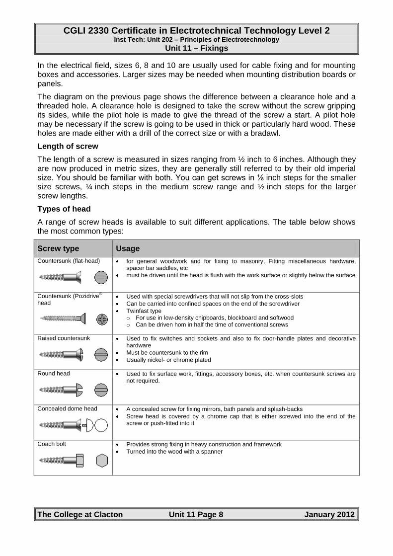
A range of screw heads is available to suit different applications. The table below shows the most common types:
Screw type Usage
Countersunk (flat-head) for general woodwork and for fixing to masonry, Fitting miscellaneous hardware, spacer bar saddles, etc
must be driven until the head is flush with the work surface or slightly below the surface
Countersunk (Pozidrive
®
head Used with special screwdrivers that will not slip from the cross-slots
Can be carried into confined spaces on the end of the screwdriver
Twinfast type o For use in low-density chipboards, blockboard and softwood o Can be driven hom in half the time of conventional screws
Raised countersunk Used to fix switches and sockets and also to fix door-handle plates and decorative
hardware
Must be countersunk to the rim
Usually nickel- or chrome plated
Round head Used to fix surface work, fittings, accessory boxes, etc. when countersunk screws are
not required.
Concealed dome head A concealed screw for fixing mirrors, bath panels and splash-backs
Screw head is covered by a chrome cap that is either screwed into the end of the screw or push-fitted into it
Coach bolt Provides strong fixing in heavy construction and framework
Turned into the wood with a spanner
CGLI 2330 Certificate in Electrotechnical Technology Level 2 Inst Tech: Unit 202 – Principles of Electrotechnology
Unit 11 – Fixings
The College at Clacton Unit 11 Page 9 January 2012
Types of metal used
The two main materials used are steel and brass.
Steel screws may be supplied with a bare finish or with a black, enamel-like paint known as ‘black japanned’, which helps prevent rust. They can also be cadmium coated for rust prevention. Brass screws are either left bare or chrome plated.
The choice of material may be dictated by strength requirement – if a load-bearing capability is required, you must use steel screws.
The finish of screw is often just a matter of aesthetics.
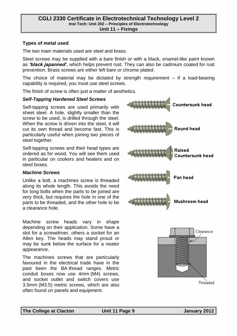
Self-Tapping Hardened Steel Screws
Self-tapping screws are used primarily with sheet steel. A hole, slightly smaller than the screw to be used, is drilled through the steel. When the screw is driven into the steel, it will cut its own thread and become fast. This is particularly useful when joining two pieces of steel together.
Self-tapping screws and their head types are ordered as for wood. You will see them used in particular on cookers and heaters and on steel boxes.
Machine Screws
Unlike a bolt, a machines screw is threaded along its whole length. This avoids the need for long bolts when the parts to be joined are very thick, but requires the hole in one of the parts to be threaded, and the other hole to be a clearance hole.
Machine screw heads vary in shape depending on their application. Some have a slot for a screwdriver, others a socket for an Allen key. The heads may stand proud or may be sunk below the surface for a neater appearance.
The machines screws that are particularly favoured in the electrical trade have in the past been the BA thread ranges. Metric conduit boxes now use 4mm (M4) screws, and socket outlet and switch covers use 3.5mm (M3.5) metric screws, which are also often found on panels and equipment.
CGLI 2330 Certificate in Electrotechnical Technology Level 2 Inst Tech: Unit 202 – Principles of Electrotechnology
Unit 11 – Fixings
The College at Clacton Unit 11 Page 10 January 2012
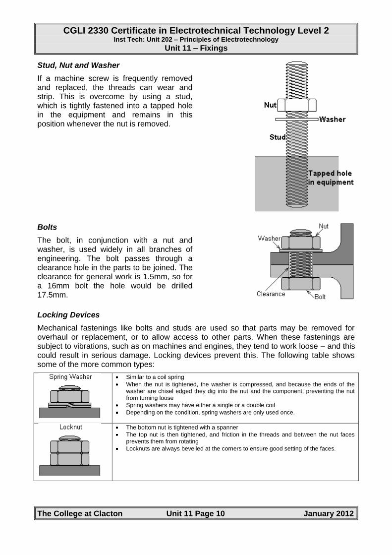
Stud, Nut and Washer
If a machine screw is frequently removed and replaced, the threads can wear and strip. This is overcome by using a stud, which is tightly fastened into a tapped hole in the equipment and remains in this position whenever the nut is removed.
Bolts
The bolt, in conjunction with a nut and washer, is used widely in all branches of engineering. The bolt passes through a clearance hole in the parts to be joined. The clearance for general work is 1.5mm, so for a 16mm bolt the hole would be drilled 17.5mm.
Locking Devices
Mechanical fastenings like bolts and studs are used so that parts may be removed for overhaul or replacement, or to allow access to other parts. When these fastenings are subject to vibrations, such as on machines and engines, they tend to work loose – and this could result in serious damage. Locking devices prevent this. The following table shows some of the more common types:
Similar to a coil spring
When the nut is tightened, the washer is compressed, and because the ends of the washer are chisel edged they dig into the nut and the component, preventing the nut from turning loose
Spring washers may have either a single or a double coil
Depending on the condition, spring washers are only used once.
The bottom nut is tightened with a spanner
The top nut is then tightened, and friction in the threads and between the nut faces prevents them from rotating
Locknuts are always bevelled at the corners to ensure good setting of the faces.
CGLI 2330 Certificate in Electrotechnical Technology Level 2 Inst Tech: Unit 202 – Principles of Electrotechnology
Unit 11 – Fixings
The College at Clacton Unit 11 Page 11 January 2012
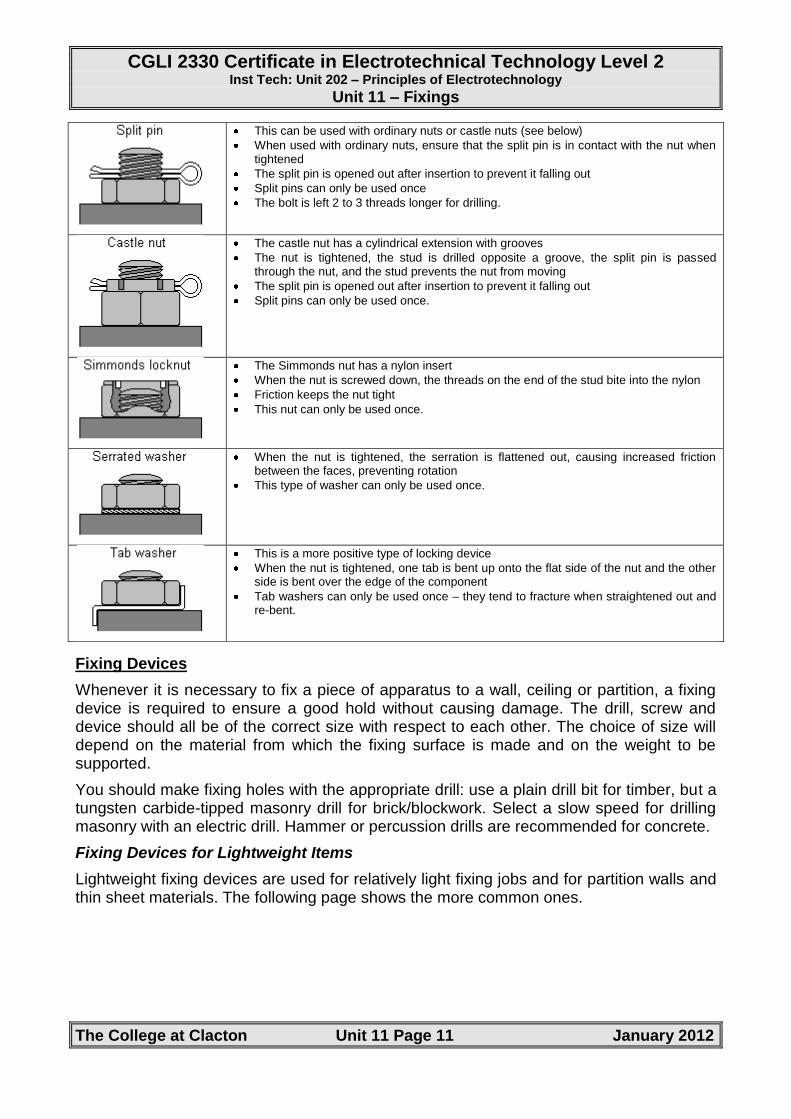
This can be used with ordinary nuts or castle nuts (see below)
When used with ordinary nuts, ensure that the split pin is in contact with the nut when tightened
The split pin is opened out after insertion to prevent it falling out
Split pins can only be used once
The bolt is left 2 to 3 threads longer for drilling.
The castle nut has a cylindrical extension with grooves
The nut is tightened, the stud is drilled opposite a groove, the split pin is passed through the nut, and the stud prevents the nut from moving
The split pin is opened out after insertion to prevent it falling out
Split pins can only be used once.
The Simmonds nut has a nylon insert
When the nut is screwed down, the threads on the end of the stud bite into the nylon
Friction keeps the nut tight
This nut can only be used once.
When the nut is tightened, the serration is flattened out, causing increased friction between the faces, preventing rotation
This type of washer can only be used once.
This is a more positive type of locking device
When the nut is tightened, one tab is bent up onto the flat side of the nut and the other side is bent over the edge of the component
Tab washers can only be used once – they tend to fracture when straightened out and re-bent.
Fixing Devices
Whenever it is necessary to fix a piece of apparatus to a wall, ceiling or partition, a fixing device is required to ensure a good hold without causing damage. The drill, screw and device should all be of the correct size with respect to each other. The choice of size will depend on the material from which the fixing surface is made and on the weight to be supported.
You should make fixing holes with the appropriate drill: use a plain drill bit for timber, but a tungsten carbide-tipped masonry drill for brick/blockwork. Select a slow speed for drilling masonry with an electric drill. Hammer or percussion drills are recommended for concrete.
Fixing Devices for Lightweight Items
Lightweight fixing devices are used for relatively light fixing jobs and for partition walls and thin sheet materials. The following page shows the more common ones.
CGLI 2330 Certificate in Electrotechnical Technology Level 2 Inst Tech: Unit 202 – Principles of Electrotechnology
Unit 11 – Fixings
The College at Clacton Unit 11 Page 12 January 2012
Fibre Plugs
General purpose
Size numbers match the screw numbers, so a number 12 screw should be used with a number 12 plug
Provides good holding power but may weaken with age
Supplied by the hundred, either of the same size or mixed.
Plastic Plugs
More popular than fibre plugs
Should not be used when fixing a heating appliance, such as a storage radiator, as the heat will cause the plastic to soften and the appliance could become insecure
Comes in strips of 10 or 20 in boxes of 100
Colour-coded to denote size and usage, although colours can vary between manufacturers.
Plastic Filler Type Plugs
Use loose, powdery substance tamped into the hole
Some are mixed with water first
Holding strength is not equal to fibre or plastic
Have the advantage of fitting any hole size.
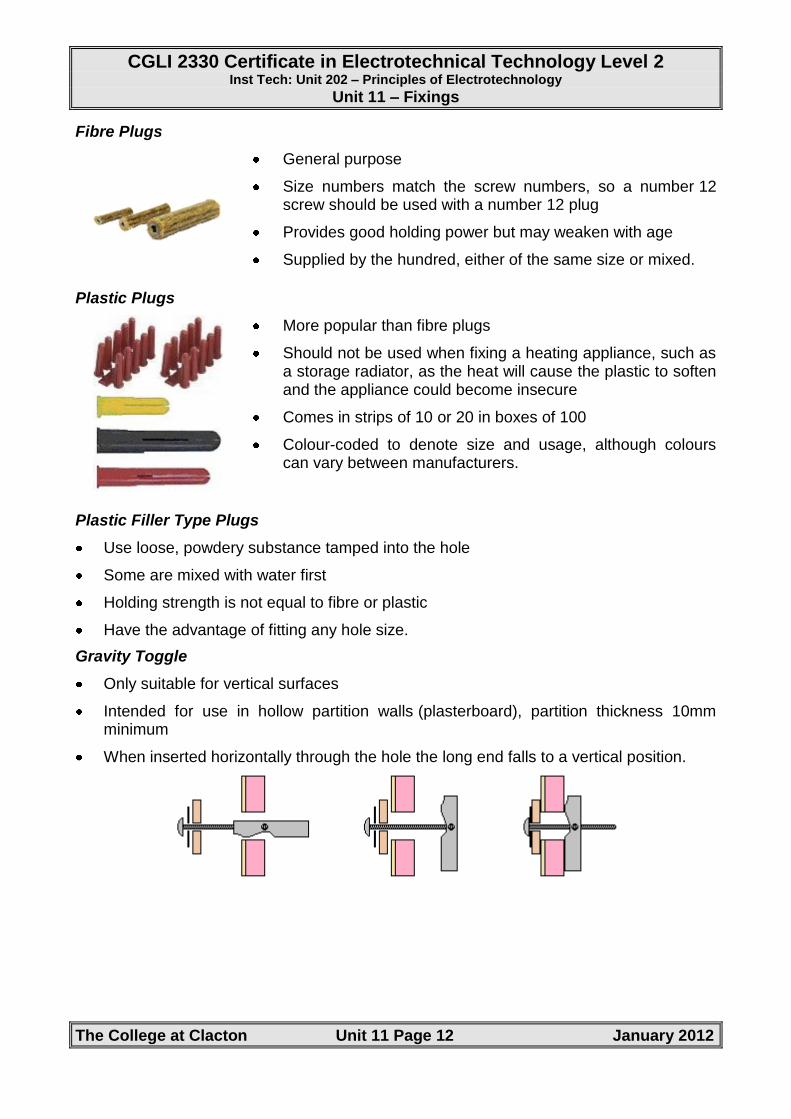
Gravity Toggle
Only suitable for vertical surfaces
Intended for use in hollow partition walls (plasterboard), partition thickness 10mm minimum
When inserted horizontally through the hole the long end falls to a vertical position.
CGLI 2330 Certificate in Electrotechnical Technology Level 2 Inst Tech: Unit 202 – Principles of Electrotechnology
Unit 11 – Fixings
The College at Clacton Unit 11 Page 13 January 2012
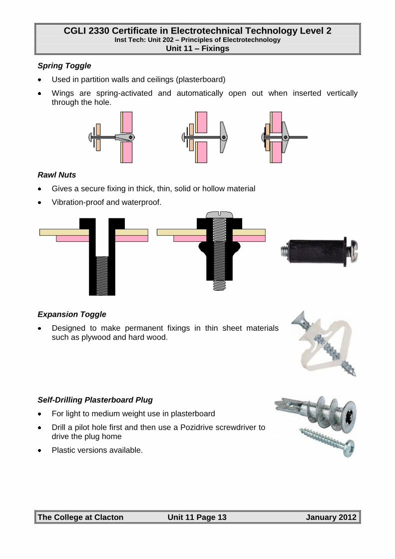
Spring Toggle
Used in partition walls and ceilings (plasterboard)
Wings are spring-activated and automatically open out when inserted vertically through the hole.
Rawl Nuts
Gives a secure fixing in thick, thin, solid or hollow material
Vibration-proof and waterproof.
Expansion Toggle
Designed to make permanent fixings in thin sheet materials such as plywood and hard wood.
Self-Drilling Plasterboard Plug
For light to medium weight use in plasterboard
Drill a pilot hole first and then use a Pozidrive screwdriver to drive the plug home
Plastic versions available.
CGLI 2330 Certificate in Electrotechnical Technology Level 2 Inst Tech: Unit 202 – Principles of Electrotechnology
Unit 11 – Fixings
The College at Clacton Unit 11 Page 14 January 2012
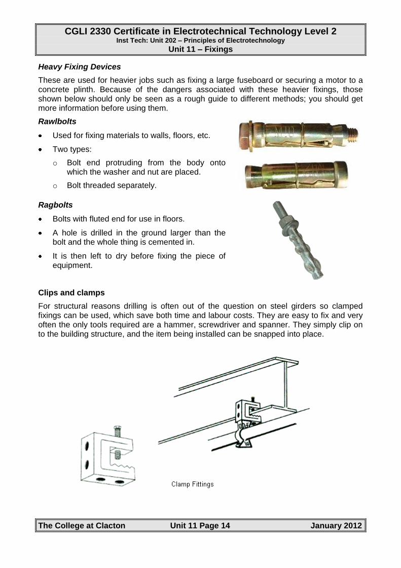
Heavy Fixing Devices
These are used for heavier jobs such as fixing a large fuseboard or securing a motor to a concrete plinth. Because of the dangers associated with these heavier fixings, those shown below should only be seen as a rough guide to different methods; you should get more information before using them.
Rawlbolts
Used for fixing materials to walls, floors, etc.
Two types:
o Bolt end protruding from the body onto which the washer and nut are placed.
o Bolt threaded separately.
Ragbolts
Bolts with fluted end for use in floors.
A hole is drilled in the ground larger than the bolt and the whole thing is cemented in.
It is then left to dry before fixing the piece of equipment.
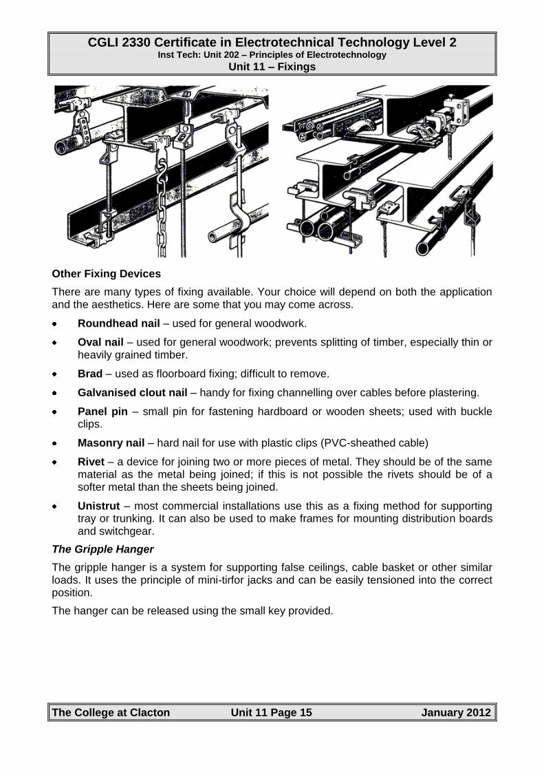
Clips and clamps
For structural reasons drilling is often out of the question on steel girders so clamped fixings can be used, which save both time and labour costs. They are easy to fix and very often the only tools required are a hammer, screwdriver and spanner. They simply clip on to the building structure, and the item being installed can be snapped into place.
CGLI 2330 Certificate in Electrotechnical Technology Level 2 Inst Tech: Unit 202 – Principles of Electrotechnology
Unit 11 – Fixings
The College at Clacton Unit 11 Page 15 January 2012
Other Fixing Devices
There are many types of fixing available. Your choice will depend on both the application and the aesthetics. Here are some that you may come across.
Roundhead nail – used for general woodwork.
Oval nail – used for general woodwork; prevents splitting of timber, especially thin or heavily grained timber.
Brad – used as floorboard fixing; difficult to remove.
Galvanised clout nail – handy for fixing channelling over cables before plastering.
Panel pin – small pin for fastening hardboard or wooden sheets; used with buckle clips.
Masonry nail – hard nail for use with plastic clips (PVC-sheathed cable)
Rivet – a device for joining two or more pieces of metal. They should be of the same material as the metal being joined; if this is not possible the rivets should be of a softer metal than the sheets being joined.
Unistrut – most commercial installations use this as a fixing method for supporting tray or trunking. It can also be used to make frames for mounting distribution boards and switchgear.
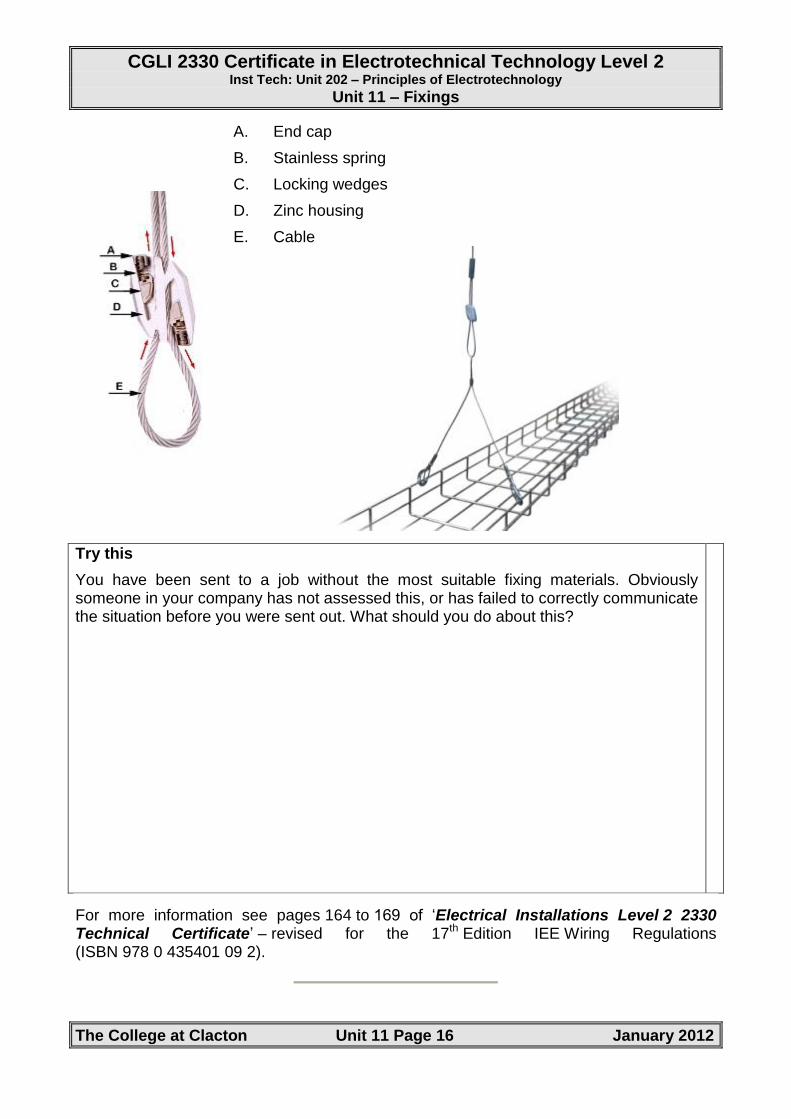
The Gripple Hanger
The gripple hanger is a system for supporting false ceilings, cable basket or other similar loads. It uses the principle of mini-tirfor jacks and can be easily tensioned into the correct position.
The hanger can be released using the small key provided.
CGLI 2330 Certificate in Electrotechnical Technology Level 2 Inst Tech: Unit 202 – Principles of Electrotechnology
Unit 11 – Fixings
The College at Clacton Unit 11 Page 16 January 2012
A. End cap
B. Stainless spring
C. Locking wedges
D. Zinc housing
E. Cable
Try this
You have been sent to a job without the most suitable fixing materials. Obviously someone in your company has not assessed this, or has failed to correctly communicate the situation before you were sent out. What should you do about this?
For more information see pages 164 to 169 of ‘Electrical Installations Level 2 2330 Technical Certificate’ – revised for the 17th Edition IEE Wiring Regulations (ISBN 978 0 435401 09 2).