Embed Size (px)
Citation preview
Questions, problems, missing parts? Before returning to your retailer, call our customer service department at 1-800-643-0067, 8 a.m. - 6 p.m., EST, Monday - Thursday, 8 a.m. - 5 p.m., EST, Friday. p.m., EST, Monday - Friday.
1
ATTACH YOUR RECEIPT HERE
Serial Number _________________________ Purchase Date _________________________
Lowes.com/harborbreeze
Harbor Breeze® is a registered trademark of LF, LLC. All Rights Reserved.
XXXXX
ITEM #0044687, 0043676, 0044622
CROSSWINDS CEILING FANMODEL #40093, 40091, 40092
Español p. 25
2Lowes.com/harborbreeze
TABLE OF CONTENTS
Package Contents . . . . . . . . . . . . . . . . . . . . . . . . . . . . . . . . . . . . . . . . . . . . . . . . . . . . . . . . . . . . . . . . . 3
Hardware Contents . . . . . . . . . . . . . . . . . . . . . . . . . . . . . . . . . . . . . . . . . . . . . . . . . . . . . . . . . . . . . . . . 4
Safety Information . . . . . . . . . . . . . . . . . . . . . . . . . . . . . . . . . . . . . . . . . . . . . . . . . . . . . . . . . . . . . . . . . 5
Preparation . . . . . . . . . . . . . . . . . . . . . . . . . . . . . . . . . . . . . . . . . . . . . . . . . . . . . . . . . . . . . . . . . . . . . . 6
Initial Installation . . . . . . . . . . . . . . . . . . . . . . . . . . . . . . . . . . . . . . . . . . . . . . . . . . . . . . . . . . . . . . . . . . 7
Standard or Angle Mounting Instructions. . . . . . . . . . . . . . . . . . . . . . . . . . . . . . . . . . . . . . . . . . . . . . . . 9
Closemount Instructions . . . . . . . . . . . . . . . . . . . . . . . . . . . . . . . . . . . . . . . . . . . . . . . . . . . . . . . . . . . 12
Wiring . . . . . . . . . . . . . . . . . . . . . . . . . . . . . . . . . . . . . . . . . . . . . . . . . . . . . . . . . . . . . . . . . . . . . . . . . 13
Final Installation. . . . . . . . . . . . . . . . . . . . . . . . . . . . . . . . . . . . . . . . . . . . . . . . . . . . . . . . . . . . . . . . . . 14
Operating Instructions . . . . . . . . . . . . . . . . . . . . . . . . . . . . . . . . . . . . . . . . . . . . . . . . . . . . . . . . . . . . . 19
Care and Maintenance . . . . . . . . . . . . . . . . . . . . . . . . . . . . . . . . . . . . . . . . . . . . . . . . . . . . . . . . . . . . 21
Troubleshooting . . . . . . . . . . . . . . . . . . . . . . . . . . . . . . . . . . . . . . . . . . . . . . . . . . . . . . . . . . . . . . . . . . 21
Limited Lifetime Warranty . . . . . . . . . . . . . . . . . . . . . . . . . . . . . . . . . . . . . . . . . . . . . . . . . . . . . . . . . . 23
Replacement Parts List . . . . . . . . . . . . . . . . . . . . . . . . . . . . . . . . . . . . . . . . . . . . . . . . . . . . . . . . . . . . 24
3Lowes.com/harborbreeze
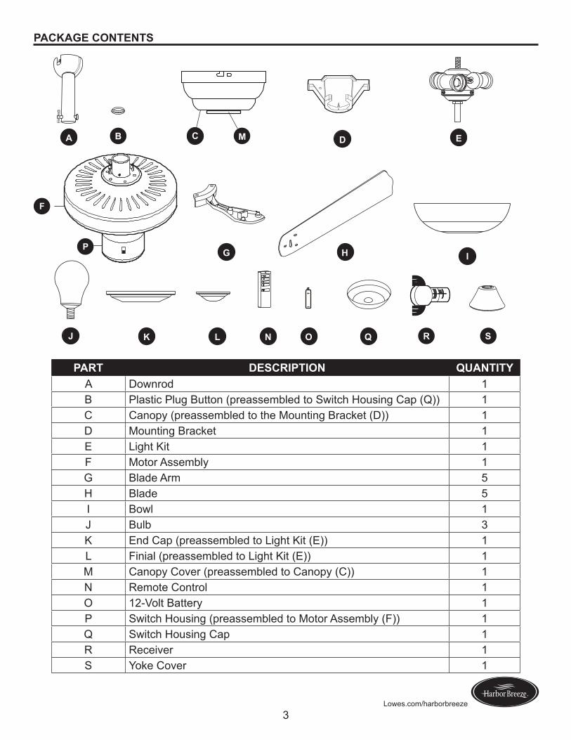
PACKAGE CONTENTS
A
I
O QJ K L
M
N
G
C
H
D E
F
P
R
B
S
PART DESCRIPTION QUANTITYA Downrod 1B Plastic Plug Button (preassembled to Switch Housing Cap (Q)) 1C Canopy (preassembled to the Mounting Bracket (D)) 1D Mounting Bracket 1E Light Kit 1F Motor Assembly 1G Blade Arm 5H Blade 5I Bowl 1J Bulb 3K End Cap (preassembled to Light Kit (E)) 1L Finial (preassembled to Light Kit (E)) 1M Canopy Cover (preassembled to Canopy (C)) 1N Remote Control 1O 12-Volt Battery 1P Switch Housing (preassembled to Motor Assembly (F)) 1Q Switch Housing Cap 1R Receiver 1S Yoke Cover 1
4Lowes.com/harborbreeze
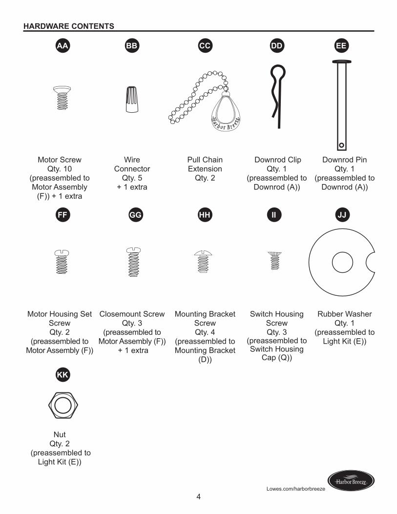
HARDWARE CONTENTS
Motor Screw Qty. 10
(preassembled to Motor Assembly
(F)) + 1 extra
Wire Connector
Qty. 5+ 1 extra
Pull Chain Extension
Qty. 2
Downrod ClipQty. 1
(preassembled to Downrod (A))
Downrod Pin Qty. 1
(preassembled to Downrod (A))
Motor Housing Set Screw Qty. 2
(preassembled to Motor Assembly (F))
Closemount Screw Qty. 3
(preassembled to Motor Assembly (F))
+ 1 extra
Mounting Bracket Screw Qty. 4
(preassembled to Mounting Bracket
(D))
Switch Housing Screw Qty. 3
(preassembled to Switch Housing
Cap (Q))
Rubber Washer Qty. 1
(preassembled to Light Kit (E))
Nut Qty. 2
(preassembled to Light Kit (E))
AA BB CC DD EE
FF
KK
GG HH II JJ
5Lowes.com/harborbreeze
SAFETY INFORMATIONPlease read and understand this entire manual before attempting to assemble, operate, or install the product.• Before you begin installing the fan, disconnect the power by removing fuses or turning off the circuit
breakers.• Make sure that all electrical connections comply with local codes, ordinances, the National ElectricalCode,andANSI/NFPA70-199.Hireaqualifiedelectricianorconsultado-it-yourselfwiring handbook if you are unfamiliar with installing electrical wiring.
• Make sure the installation site you choose allows a minimum clearance of 7 ft. from the blades to thefloorandatleast30in.fromtheendofthebladestoanyobstruction.
• The net weight of this fan is: 18.04 lbs.
DANGER: When using an existing outlet box, make sure the outlet box is securely attached to the building structure and can support the full weight of the fan. Failure to do this can result in serious injury or death. The stability of the outlet box is essential in minimizing wobble and noise in the fan after installation is complete.
WARNING: To avoid personal injury, the use of gloves may be necessary while handling fan parts with sharp edges.
WARNING: Using a full-range dimmer switch to control fan speed will cause a loud humming noisefromthefan.Toreducetheriskoffireorelectricshock,doNOTuseafull-rangedimmerswitchto control the fan speed.
WARNING: Toreducetheriskoffire,electricshock,orpersonalinjury,mountthefantoanoutlet box marked “ACCEPTABLE FOR FAN SUPPORT” and use the mounting screws provided with theoutletbox.Mostoutletboxescommonlyusedforthesupportoflightingfixturesarenotacceptableforfansupportandmayneedtobereplaced.Consultaqualifiedelectricianifindoubt.Securetheoutlet box directly to the building structure. The outlet box and its support must be able to support the moving weight of the fan (at least 35 lbs.). Do NOT use a plastic outlet box.
WARNING: Toreducetheriskoffire,electricalshock,orpersonalinjury,wireconnectorsprovided with this fan are designed to accept only one 12-gauge house wire and two lead wires from the fan. If your house wire is larger than 12 gauges or there is more than one house wire to connect to the two fan lead wires, consult an electrician for the proper size wire connectors to use.
WARNING: Toreducetheriskoffireorelectricshock,donotusethefanwithanysolid-statespeed-control device or control the fan speed with a full-range dimmer switch.
WARNING: Toreducetheriskoffire,electricshock,orpersonalinjury,donotbendthebladearms when installing them, balancing the blades, or cleaning the fan. Do not insert objects between the rotating fan blades.
WARNING: To reduce the risk of personal injury, use only parts provided with this fan. The use of parts OTHER than those provided with this fan will void the warranty.
6Lowes.com/harborbreeze
SAFETY INFORMATIONCAUTION: Read all instructions and safety information before installing your new fan. Review the accompanying assembly diagrams.
CAUTION: Be sure the outlet box is properly grounded or that a ground (green or bare) wire is present.
CAUTION: Carefully check all screws, bolts, and nuts on the fan motor assembly to ensure that they are secured.
CAUTION: This equipment has been tested and found to comply with the limits for a Class B digital device, pursuant to Part 15 of the FCC Rules. These limits are designed to provide reasonable protection against harmful interference in a residential installation. This equipment generates, uses and can radiate radio frequency energy and, if not installed and used in accordance with the instructions, may cause harmful interference to radio communications.
PREPARATION
Before beginning the assembly of this product, ensure all parts are present. Compare all parts with the package contents list and hardware contents list. If any part is missing or damaged, do not attempt to assemble the product.
After opening the top of the carton, remove the mounting hardware package from the foam inserts, then remove the motor from the packaging and place it on a soft surface, such as a carpet, to avoid damagetothefinish.
Estimated Assembly Time: 120 minutes
Tools Required for Assembly (not included): Electrical Tape, Phillips Screwdriver, Pliers, Safety Glasses, Step Ladder, and Wire Strippers
Helpful Tools (not included): AC Tester Light, Tape Measure, Wiring Handbook and Wire Cutters

7Lowes.com/harborbreeze
INITIAL INSTALLATION1. Turn off the circuit breakers and the wall switch to the
fan supply line leads.
DANGER: Failure to disconnect the power supply prior to installation may result in serious injury or death.
1
2. Determine the mounting method to use.
Note:� Flushmount installation is not available for this item.
Impootaat:� If using the angle mount, check to ensure the ceiling angle is not steeper than 25°.
2
Downrod Mounting
Flushmount Closemount
Angle Mounting
3. Ensure the blades (H) will be at least 30 in. from any obstructions. Also check the downrod (A) length to ensure the blades (H) will be at least 7 ft. above thefloor. A
H
3
7 ft. min.
30 in. min.
8Lowes.com/harborbreeze
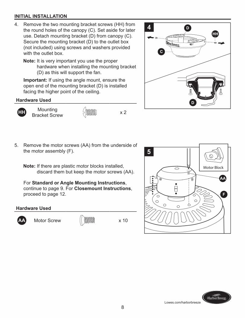
INITIAL INSTALLATION4. Remove the two mounting bracket screws (HH) from
the round holes of the canopy (C). Set aside for later use. Detach mounting bracket (D) from canopy (C). Secure the mounting bracket (D) to the outlet box (not included) using screws and washers provided with the outlet box.Note:� It is very important you use the proper
hardware when installing the mounting bracket (D) as this will support the fan.
Impootaat:� If using the angle mount, ensure the open end of the mounting bracket (D) is installed facing the higher point of the ceiling.
Haodwaoe Used
HH Mounting Bracket Screw x 2
D
4
C
HHD
5. Remove the motor screws (AA) from the underside of the motor assembly (F).
Note:� If there are plastic motor blocks installed, discard them but keep the motor screws (AA).
Haodwaoe Used
AA Motor Screw x 10
AA
5
Motor Block
F
For Staadaod oo Aagle Mouatiag Iastouctioas, continue to page 9. For Closemouat Iastouctioas, proceed to page 12.
9Lowes.com/harborbreeze
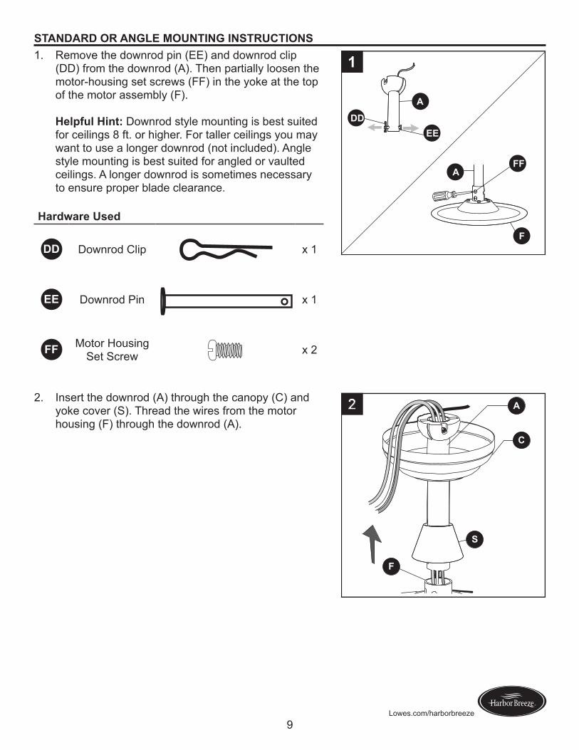
STANDARD OR ANGLE MOUNTING INSTRUCTIONS1. Remove the downrod pin (EE) and downrod clip
(DD) from the downrod (A). Then partially loosen the motor-housing set screws (FF) in the yoke at the top of the motor assembly (F).
Helpful Hiat: Downrod style mounting is best suited for ceilings 8 ft. or higher. For taller ceilings you may want to use a longer downrod (not included). Angle style mounting is best suited for angled or vaulted ceilings. A longer downrod is sometimes necessary to ensure proper blade clearance.
Haodwaoe Used
DD Downrod Clip x 1
EE Downrod Pin x 1
FF Motor Housing Set Screw x 2
F
A
DDEE
FFA
1
2. Insert the downrod (A) through the canopy (C) and yoke cover (S). Thread the wires from the motor housing (F) through the downrod (A).
A
C
S
F
2
10Lowes.com/harborbreeze
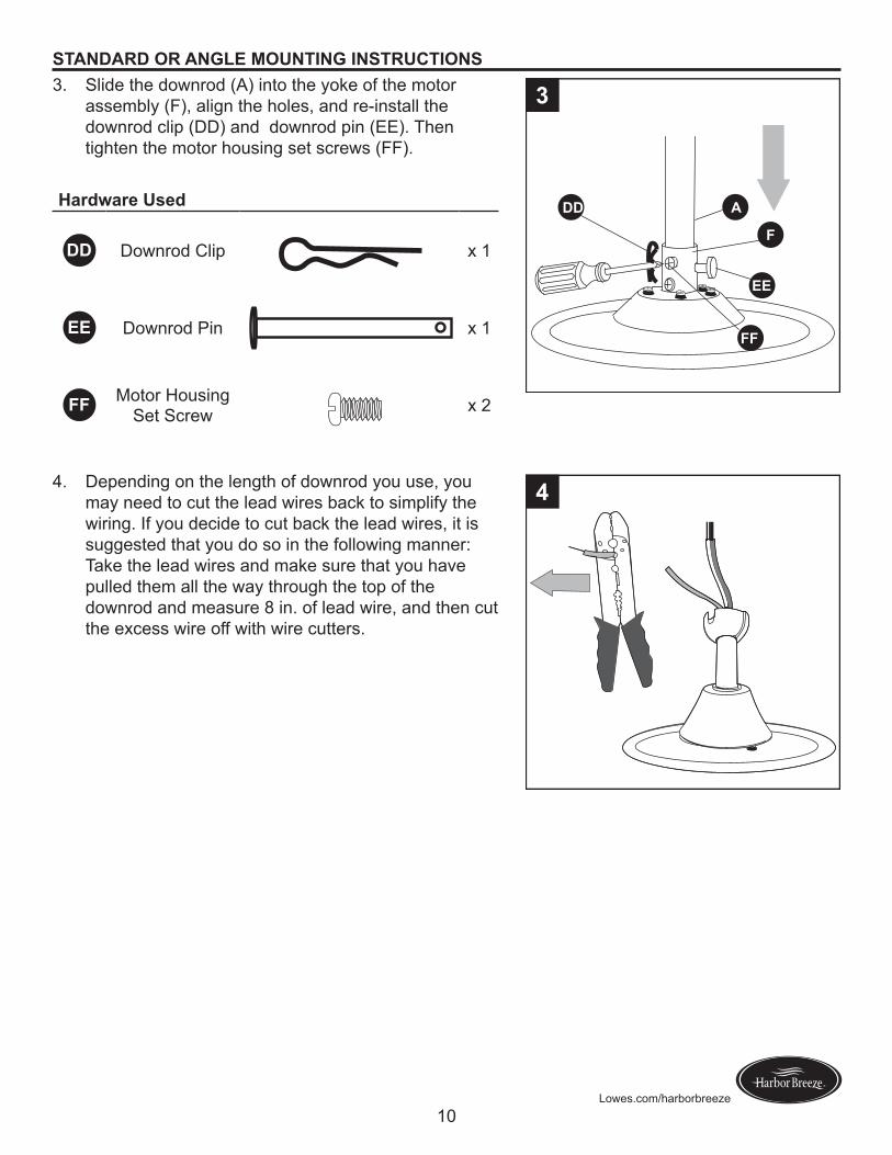
STANDARD OR ANGLE MOUNTING INSTRUCTIONS3. Slide the downrod (A) into the yoke of the motor
assembly (F), align the holes, and re-install the downrod clip (DD) and downrod pin (EE). Then tighten the motor housing set screws (FF).
Haodwaoe Used
DD Downrod Clip x 1
EE Downrod Pin x 1
FF Motor Housing Set Screw x 2
DD
FF
A
F
EE
3
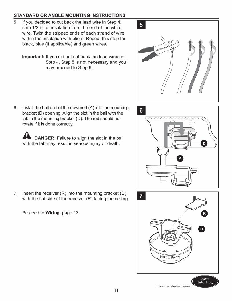
4. Depending on the length of downrod you use, you may need to cut the lead wires back to simplify the wiring. If you decide to cut back the lead wires, it is suggested that you do so in the following manner: Take the lead wires and make sure that you have pulled them all the way through the top of the downrod and measure 8 in. of lead wire, and then cut the excess wire off with wire cutters.
4
11Lowes.com/harborbreeze
STANDARD OR ANGLE MOUNTING INSTRUCTIONS5. If you decided to cut back the lead wire in Step 4,
strip 1/2 in. of insulation from the end of the white wire. Twist the stripped ends of each strand of wire within the insulation with pliers. Repeat this step for black, blue (if applicable) and green wires.
Impootaat:� If you did not cut back the lead wires in Step 4, Step 5 is not necessary and you may proceed to Step 6.
5
6. Install the ball end of the downrod (A) into the mounting bracket (D) opening. Align the slot in the ball with the tab in the mounting bracket (D). The rod should not rotate if it is done correctly.
DANGER: Failure to align the slot in the ball with the tab may result in serious injury or death.
D
A
6
7. Insert the receiver (R) into the mounting bracket (D) withtheflatsideofthereceiver(R)facingtheceiling.
Proceed to Wioiag, page 13.
D
R
7
12Lowes.com/harborbreeze
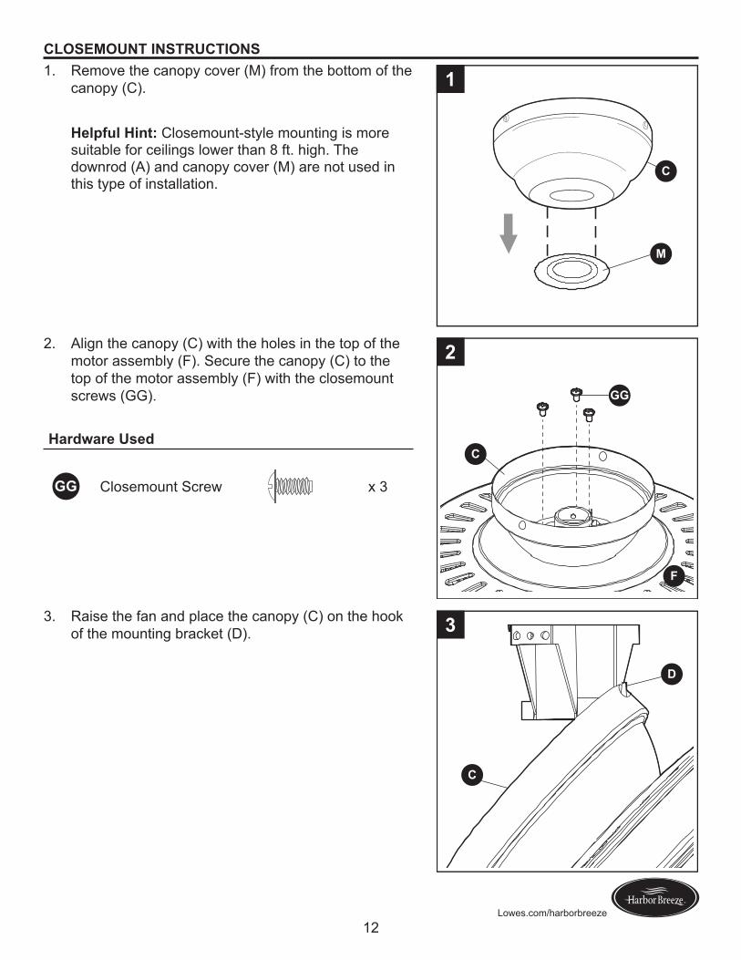
CLOSEMOUNT INSTRUCTIONS1. Remove the canopy cover (M) from the bottom of the
canopy (C).
Helpful Hiat: Closemount-style mounting is more suitable for ceilings lower than 8 ft. high. The downrod (A) and canopy cover (M) are not used in this type of installation.
1
M
C
2. Align the canopy (C) with the holes in the top of the motor assembly (F). Secure the canopy (C) to the top of the motor assembly (F) with the closemount screws (GG).
Haodwaoe Used
GG Closemount Screw x 3
F
C
GG
2
3. Raise the fan and place the canopy (C) on the hook of the mounting bracket (D).
C
D
3
13Lowes.com/harborbreeze
WIRING
WARNING:Toreducetheriskoffire,electricalshock,orpersonalinjury,wireconnectorsprovided with this fan are designed to accept only one 12-gauge house wire and two lead wires from the fan. If your house wire is larger than 12 gauges and there is more than one house wire to connect to the two fan lead wires, consult an electrician for the proper size wire connectors to use.
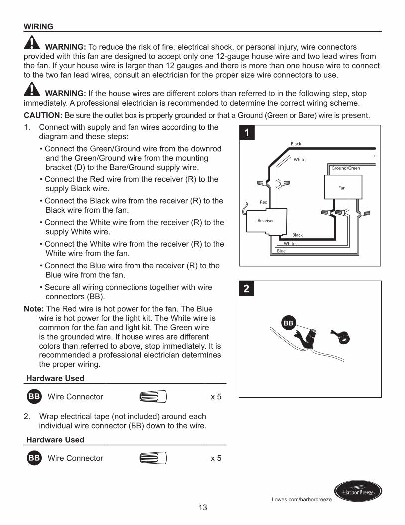
WARNING: If the house wires are different colors than referred to in the following step, stop immediately. A professional electrician is recommended to determine the correct wiring scheme.CAUTION: Be sure the outlet box is properly grounded or that a Ground (Green or Bare) wire is present.1. Connect with supply and fan wires according to the
diagram and these steps:•ConnecttheGreen/Groundwirefromthedownrod
and the Green/Ground wire from the mounting bracket (D) to the Bare/Ground supply wire.
•ConnecttheRedwirefromthereceiver(R)tothesupply Black wire.
•ConnecttheBlackwirefromthereceiver(R)totheBlack wire from the fan.
•ConnecttheWhitewirefromthereceiver(R)tothesupply White wire.
•ConnecttheWhitewirefromthereceiver(R)totheWhite wire from the fan.
•ConnecttheBluewirefromthereceiver(R)totheBlue wire from the fan.
•Secureallwiringconnectionstogetherwithwireconnectors (BB).
Note: The Red wire is hot power for the fan. The Blue wire is hot power for the light kit. The White wire is common for the fan and light kit. The Green wire is the grounded wire. If house wires are different colors than referred to above, stop immediately. It is recommended a professional electrician determines the proper wiring.
Haodwaoe Used
BB Wire Connector x 5
Receiver
Fan
Black
Black
Blue
White
Ground/Green
White
1
Red
2. Wrap electrical tape (not included) around each individual wire connector (BB) down to the wire.
Haodwaoe Used
BB Wire Connector x 5
BB
2
14Lowes.com/harborbreeze
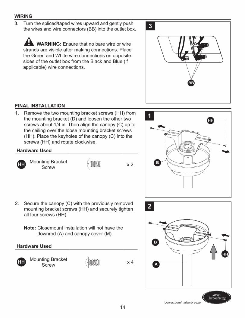
WIRING3. Turn the spliced/taped wires upward and gently push
the wires and wire connectors (BB) into the outlet box.
WARNING: Ensure that no bare wire or wire strands are visible after making connections. Place the Green and White wire connections on opposite sides of the outlet box from the Black and Blue (if applicable) wire connections.
BB
3
FINAL INSTALLATION1. Remove the two mounting bracket screws (HH) from
the mounting bracket (D) and loosen the other two screws about 1/4 in. Then align the canopy (C) up to the ceiling over the loose mounting bracket screws (HH). Place the keyholes of the canopy (C) into the screws (HH) and rotate clockwise.
Haodwaoe Used
HH Mounting Bracket Screw x 2 B
HH1
2. Secure the canopy (C) with the previously removed mounting bracket screws (HH) and securely tighten all four screws (HH).
Note:� Closemount installation will not have the downrod (A) and canopy cover (M).
Haodwaoe Used
HH Mounting Bracket Screw x 4
B
J
HH
A
II
2
15Lowes.com/harborbreeze
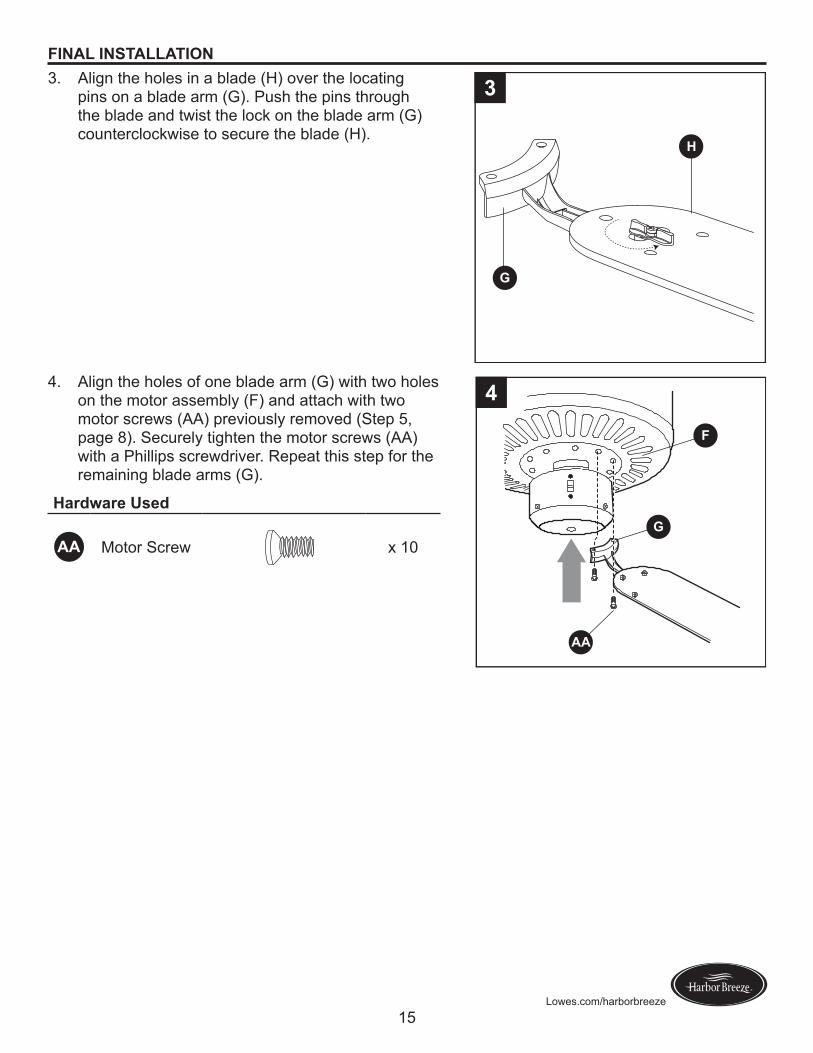
FINAL INSTALLATION3. Align the holes in a blade (H) over the locating
pins on a blade arm (G). Push the pins through the blade and twist the lock on the blade arm (G) counterclockwise to secure the blade (H).
3
G
H
4. Align the holes of one blade arm (G) with two holes on the motor assembly (F) and attach with two motor screws (AA) previously removed (Step 5, page 8). Securely tighten the motor screws (AA) with a Phillips screwdriver. Repeat this step for the remaining blade arms (G).
Haodwaoe Used
AA Motor Screw x 10
4
AA
F
G
16Lowes.com/harborbreeze
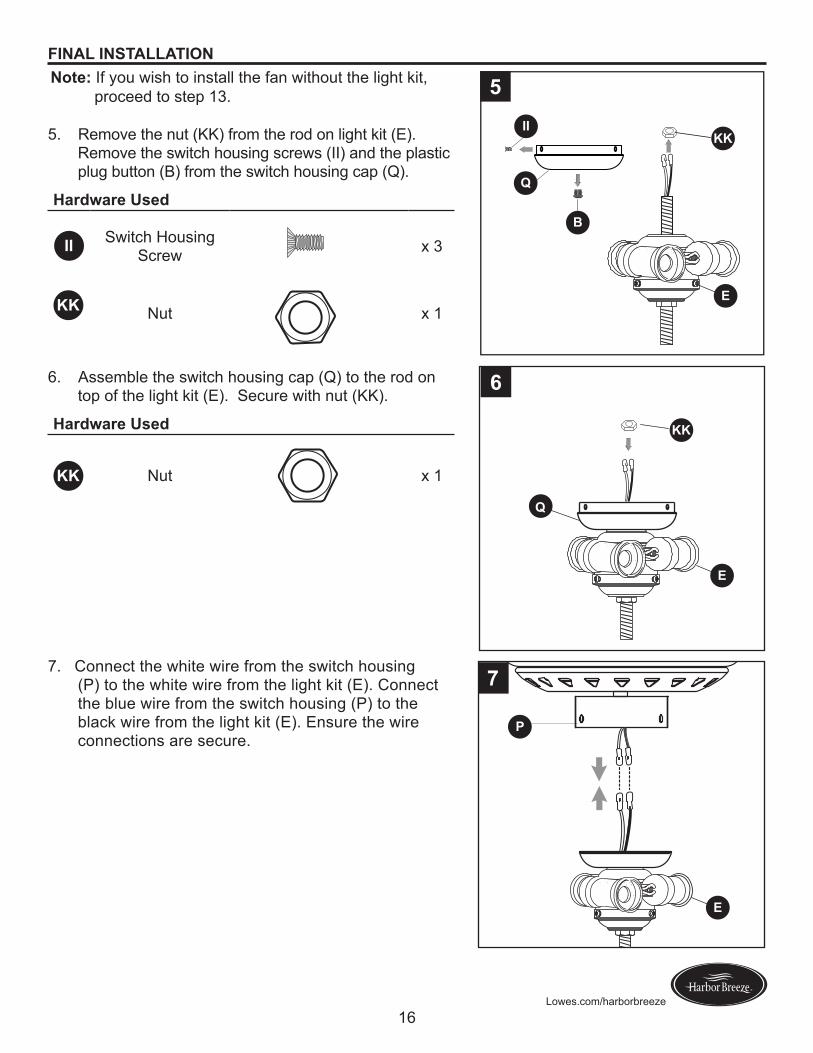
FINAL INSTALLATIONNote:� If you wish to install the fan without the light kit,
proceed to step 13.
5. Remove the nut (KK) from the rod on light kit (E). Remove the switch housing screws (II) and the plastic plug button (B) from the switch housing cap (Q).
Haodwaoe Used
II Switch Housing Screw x 3
Nut x 1
5
E
KK
Q
B
II
6. Assemble the switch housing cap (Q) to the rod on top of the light kit (E). Secure with nut (KK).
Haodwaoe Used
Nut x 1
7. Connect the white wire from the switch housing (P) to the white wire from the light kit (E). Connect the blue wire from the switch housing (P) to the black wire from the light kit (E). Ensure the wire connections are secure.
P
E
7
KK
6
Q
E
KK
KK
17Lowes.com/harborbreeze
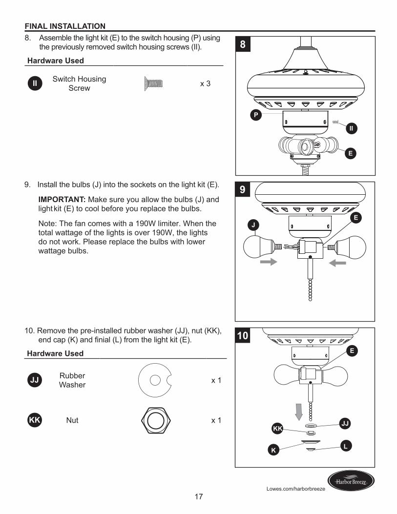
FINAL INSTALLATION8. Assemble the light kit (E) to the switch housing (P) using
the previously removed switch housing screws (II).
Haodwaoe Used
II Switch Housing Screw x 3
P
E
II
8
9. Install the bulbs (J) into the sockets on the light kit (E).
IMPORTANT: Make sure you allow the bulbs (J) and light kit (E) to cool before you replace the bulbs.
Note: The fan comes with a 190W limiter. When the total wattage of the lights is over 190W, the lights do not work. Please replace the bulbs with lower wattage bulbs.
EJ
9
10. Remove the pre-installed rubber washer (JJ), nut (KK), endcap(K)andfinial(L)fromthelightkit(E).
Haodwaoe Used
JJ Rubber Washer x 1
KK Nut x 1
E
10
K L
JJKK
18Lowes.com/harborbreeze
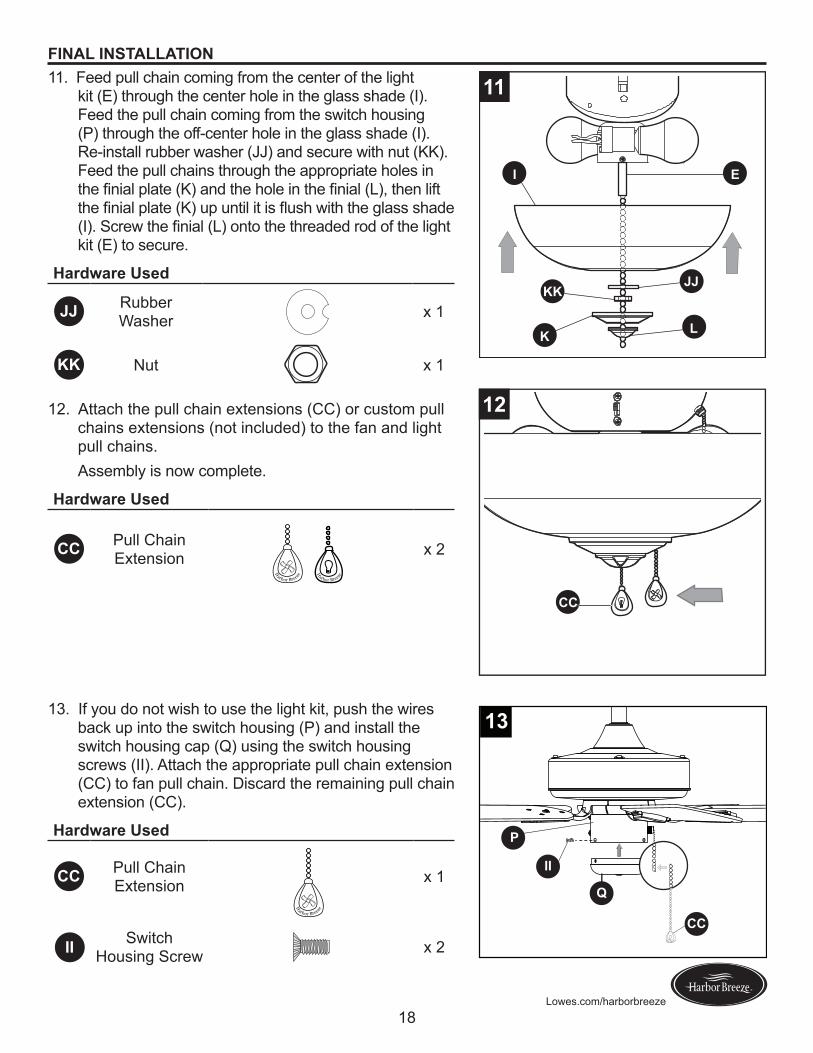
11. Feed pull chain coming from the center of the light kit (E) through the center hole in the glass shade (I). Feed the pull chain coming from the switch housing (P) through the off-center hole in the glass shade (I). Re-install rubber washer (JJ) and secure with nut (KK). Feed the pull chains through the appropriate holes in thefinialplate(K)andtheholeinthefinial(L),thenliftthefinialplate(K)upuntilitisflushwiththeglassshade(I).Screwthefinial(L)ontothethreadedrodofthelightkit (E) to secure.
Haodwaoe Used
JJ Rubber Washer x 1
KK Nut x 1
I E
K L
JJKK
11
12. Attach the pull chain extensions (CC) or custom pull chains extensions (not included) to the fan and light pull chains.Assembly is now complete.
Haodwaoe Used
CC Pull Chain Extension x 2
13. If you do not wish to use the light kit, push the wires back up into the switch housing (P) and install the switch housing cap (Q) using the switch housing screws (II). Attach the appropriate pull chain extension (CC) to fan pull chain. Discard the remaining pull chain extension (CC).
Haodwaoe Used
CC Pull Chain Extension x 1
Switch Housing Screw x 2
P
Q
CC
II
H
arbor Breeze
13
FINAL INSTALLATION
II
H
arbor Breeze
H
arbor
Breeze
H
arbor Breeze
12
CC
19Lowes.com/harborbreeze
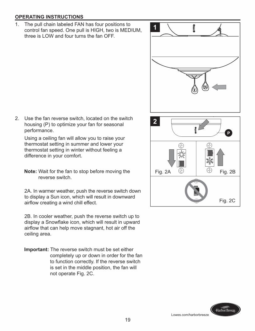
OPERATING INSTRUCTIONS1. The pull chain labeled FAN has four positions to
control fan speed. One pull is HIGH, two is MEDIUM, three is LOW and four turns the fan OFF.
1
2. Use the fan reverse switch, located on the switch housing (P) to optimize your fan for seasonal performance.Using a ceiling fan will allow you to raise your thermostat setting in summer and lower your thermostat setting in winter without feeling a difference in your comfort.
Note:� Wait for the fan to stop before moving the reverse switch.
2A. In warmer weather, push the reverse switch down to display a Sun icon, which will result in downward airflowcreatingawindchilleffect.
2B. In cooler weather, push the reverse switch up to displayaSnowflakeicon,whichwillresultinupwardairflowthatcanhelpmovestagnant,hotairofftheceiling area.
Impootaat:� The reverse switch must be set either completely up or down in order for the fan to function correctly. If the reverse switch is set in the middle position, the fan will not operate Fig. 2C.
Fig. 2A Fig. 2B
Fig. 2C
P
2
20Lowes.com/harborbreeze
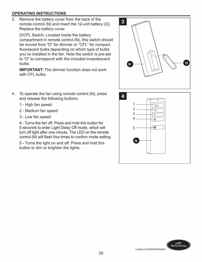
OPERATING INSTRUCTIONS3. Remove the battery cover from the back of the
remote control (N) and insert the 12-volt battery (O). Replace the battery cover.D/CFL Switch: Located inside the battery compartment in remote control (N), this switch should be moved from “D” for dimmer or “CFL” for compact fluorescentbulbsdependingonwhichtypeofbulbsyou’ve installed in the fan. Note the switch is pre-set to “D” to correspond with the included incandescent bulbs.IMPORTANT: The dimmer function does not work with CFL bulbs.
N O
O P
3
4. To operate the fan using remote control (N), press and release the following buttons:1 - High fan speed2 - Medium fan speed3 - Low fan speed4 - Turns the fan off. Press and hold this button for 5 seconds to enter Light Delay Off mode, which will turn off light after one minute. The LED on the remote control(N)willflashfourtimestoconfirmmodesetting.5 - Turns the light on and off. Press and hold this button to dim or brighten the lights.
N
O P
1234
5
4
21Lowes.com/harborbreeze
CARE AND MAINTENANCE
At least twice each year, lower the canopy to check the downrod assembly, and then tighten all screws on the fan. Clean the motor housing with only a soft brush or lint-free cloth to avoid scratching thefinish.Cleanthebladeswithalint-freecloth.Youmayoccasionallyapplyalightcoatoffurniturepolish to wood blades for added protection. Bulb Replacemeat: Use 40-watt max. candelabra-base incandescent bulbs or a CFL equivalent.Impootaat:� Shut off the main power supply before you begin any maintenance task. Do not use water or a damp cloth to clean the fan. TROUBLESHOOTING
PROBLEM POSSIBLE CAUSE CORRECTIVE ACTION
The fan does not move.
1. The reverse switch is not engaged.
2. The wall switch is turned off.
3. The power is off or the fuse (breaker) is blown.
4. There is a faulty wire connection.
1. Firmly push the reverse switch to either the left or right.
2. Make sure the wall switch is turned on.
3. Turn the power on or check the fuse (breaker).
4. Turn the power off and check all connections at the ceiling outlet box.
The fan is noisy.
1. The blades are loose.
2. There is a cracked blade.3. The wall control is not
compatible with the fan.4. The break-in period has not
surpassed.
5. The outlet box is not secure.
6. The mounting bracket is not secure.
1. Check and tighten all screws that hold the fan blades to the blade arms and the motor.
2. Replace the cracked blade.3. Do not use a full range dimmer
switch to control the fan speed.4. Run the fan continuously for 24 - 48
hours on medium or high speed for a “break in” period.
5. Ensure the outlet box is secured to the building structure.
6. Ensure the mounting bracket is secured to the outlet box and that the screws are tight.
22Lowes.com/harborbreeze
TROUBLESHOOTING
PROBLEM POSSIBLE CAUSE CORRECTIVE ACTION
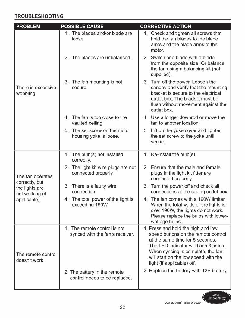
There is excessive wobbling.
1. The blades and/or blade are loose.
2. The blades are unbalanced.
3. The fan mounting is not secure.
4. The fan is too close to the vaulted ceiling.
5. The set screw on the motor housing yoke is loose.
1. Check and tighten all screws that hold the fan blades to the blade arms and the blade arms to the motor.
2. Switch one blade with a blade from the opposite side. Or balance the fan using a balancing kit (not supplied).
3. Turn off the power. Loosen the canopy and verify that the mounting bracket is secure to the electrical outlet box. The bracket must be flushwithoutmovementagainsttheoutlet box.
4. Use a longer downrod or move the fan to another location.
5. Lift up the yoke cover and tighten the set screw to the yoke until secure.
The fan operates correctly, but the lights are not working (if applicable).
1. The bulb(s) not installed correctly.
2. The light kit wire plugs are not connected properly.
3. There is a faulty wire connection.
4. The total power of the light is exceeding 190W.
1. Re-install the bulb(s).
2. Ensure that the male and female plugsinthelightkitfitterareconnected properly.
3. Turn the power off and check all connections at the ceiling outlet box.
4. The fan comes with a 190W limiter. When the total watts of the lights is over 190W, the lights do not work. Please replace the bulbs with lower-wattage bulbs.
The remote control doesn’t work.
1. The remote control is not synced with the fan’s receiver.
2. The battery in the remote control needs to be replaced.
1. Press and hold the high and low speed buttons on the remote control at the same time for 5 seconds. TheLEDindicatorwillflash3times.When syncing is complete, the fan will start on the low speed with the light (if applicable) off.
2. Replace the battery with 12V battery.
23Lowes.com/harborbreeze
LIFETIME LIMITED WARRANTY
The manufacturer warrants this fan to be free from defects in workmanship and materials present at time of shipment from the factory for a lifetime from the date of purchase by the original purchaser. The retailer also warrants that all other fan parts, excluding any glass or plexiglas blades, to be free from defects in workmanship and material at the time of shipment from the factory for a period of one year after the date of purchase by the original purchaser. The manufacturer agrees to correct such defects without charge or at its option replace the ceiling fan with a comparable or superior model.To obtain warranty service, present a copy of the receipt as proof of purchase. All costs of removing and reinstalling the product are your responsibility. Any damage to any part such as by accident or misuseorimproperinstallationorbyaffixinganyaccessories,isnotcoveredbythiswarranty.Themanufacturer assumes no responsibility whatsoever for fan installation during the limited lifetime warranty. Any service performed by an unauthorized person will render the warranty invalid.Duetovaryingclimateconditions,thiswarrantydoesnotcoveranychangesinbrassfinish,includingrusting,pitting,corroding,tarnishingorpeeling.Brassfinishesofthistypegivetheirlongestusefullifewhen protected from varying weather conditions. Any glass provided with this fan is not covered by the warranty.Anyreplacementofdefectivepartsfromtheceilingfanmustbereportedwithinthefirstyearfromthedate of purchase. For the balance of the warranty, call our customer service department for return authorization and shipping instructions so that we may repair or replace the ceiling fan. Any fan or parts returned improperly is the sole responsibility of the purchaser. There is no other expressed warranty. The manufacturer disclaims any and all warranties. The duration of any implied warranty whichcannotbedisclaimedislimitedtothetimeperiodasspecifiedintheexpressedwarranty.Themanufacturer shall not be liable for incidental, consequential, or special damages arising out of or in connection with product use or performance except as may otherwise be accorded by law. This warrantygivesspecificlegalrights,andyoumayalsohaveotherrightswhichvaryfromstatetostate.This warranty supersedes all prior warranties.Note:� A small amount of “wobble” is normal and should not be considered a defect.
24Lowes.com/harborbreeze
Printed in ChinaHarbor Breeze® is a registered trademark
of LF, LLC. All Rights Reserved.
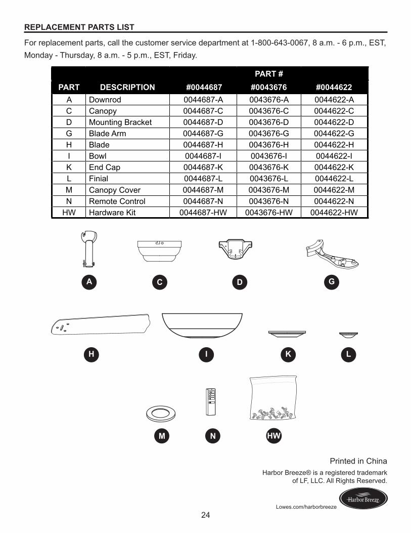
REPLACEMENT PARTS LIST
For replacement parts, call the customer service department at 1-800-643-0067, 8 a.m. - 6 p.m., EST,Monday - Thursday, 8 a.m. - 5 p.m., EST, Friday.
PART #PART DESCRIPTION #0044687 #0043676 #0044622
A Downrod 0044687-A 0043676-A 0044622-AC Canopy 0044687-C 0043676-C 0044622-CD Mounting Bracket 0044687-D 0043676-D 0044622-DG Blade Arm 0044687-G 0043676-G 0044622-GH Blade 0044687-H 0043676-H 0044622-HI Bowl 0044687-I 0043676-I 0044622-IK End Cap 0044687-K 0043676-K 0044622-KL Finial 0044687-L 0043676-L 0044622-LM Canopy Cover 0044687-M 0043676-M 0044622-MN Remote Control 0044687-N 0043676-N 0044622-N
HW Hardware Kit 0044687-HW 0043676-HW 0044622-HW
A
H L
M
C D
I
G
K
HWN
26
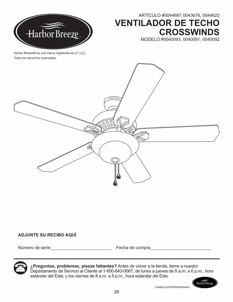
ADJUNTE SU RECIBO AQUÍ
Número de serie_________________________ Fecha de compra_________________________
Lowes.com/harborbreeze
¿Preguntas, problemas, piezas faltantes? Antes de volver a la tienda, llame a nuestro Departamento de Servicio al Cliente al 1-800-643-0067, de lunes a jueves de 8 a.m. a 6 p.m., hora estándar del Este, y los viernes de 8 a.m. a 5 p.m., hora estándar del Este.
Harbor Breeze® es una marca registrada de LF, LLC. Todos los derechos reservados.
ARTÍCULO #0044687, 0043676, 0044622
VENTILADOR DE TECHO CROSSWINDS
MODELO #0040093, 0040091, 0040092
27
Lowes.com/harborbreeze
ÍNDICE
Contenido del paquete . . . . . . . . . . . . . . . . . . . . . . . . . . . . . . . . . . . . . . . . . . . . . . . . . . . . . . . . . . . . . . . .28
Aditamentos. . . . . . . . . . . . . . . . . . . . . . . . . . . . . . . . . . . . . . . . . . . . . . . . . . . . . . . . . . . . . . . . . . . . . . . . .29
Información de seguridad . . . . . . . . . . . . . . . . . . . . . . . . . . . . . . . . . . . . . . . . . . . . . . . . . . . . . . . . . . . . . .30
Preparación . . . . . . . . . . . . . . . . . . . . . . . . . . . . . . . . . . . . . . . . . . . . . . . . . . . . . . . . . . . . . . . . . . . . . . . . .31
Instalación Inicial . . . . . . . . . . . . . . . . . . . . . . . . . . . . . . . . . . . . . . . . . . . . . . . . . . . . . . . . . . . . . . . . . . . . .32
Instrucciones estándares y de montaje en ángulo . . . . . . . . . . . . . . . . . . . . . . . . . . . . . . . . . . . . . . . . . . .34
Instrucciones para montaje cerrado . . . . . . . . . . . . . . . . . . . . . . . . . . . . . . . . . . . . . . . . . . . . . . . . . . . . . .37
Cableado . . . . . . . . . . . . . . . . . . . . . . . . . . . . . . . . . . . . . . . . . . . . . . . . . . . . . . . . . . . . . . . . . . . . . . . . . . .38
Instalación final . . . . . . . . . . . . . . . . . . . . . . . . . . . . . . . . . . . . . . . . . . . . . . . . . . . . . . . . . . . . . . . . . . . . . .39
Instrucciones de funcionamiento . . . . . . . . . . . . . . . . . . . . . . . . . . . . . . . . . . . . . . . . . . . . . . . . . . . . . . . . .44
Cuidado y mantenimiento . . . . . . . . . . . . . . . . . . . . . . . . . . . . . . . . . . . . . . . . . . . . . . . . . . . . . . . . . . . . . .46
Solución de problemas . . . . . . . . . . . . . . . . . . . . . . . . . . . . . . . . . . . . . . . . . . . . . . . . . . . . . . . . . . . . . . . .48
Garantía limitada de por vida . . . . . . . . . . . . . . . . . . . . . . . . . . . . . . . . . . . . . . . . . . . . . . . . . . . . . . . . . . .48
Lista de piezas de repuesto. . . . . . . . . . . . . . . . . . . . . . . . . . . . . . . . . . . . . . . . . . . . . . . . . . . . . . . . . . . . .49
28
Lowes.com/harborbreeze
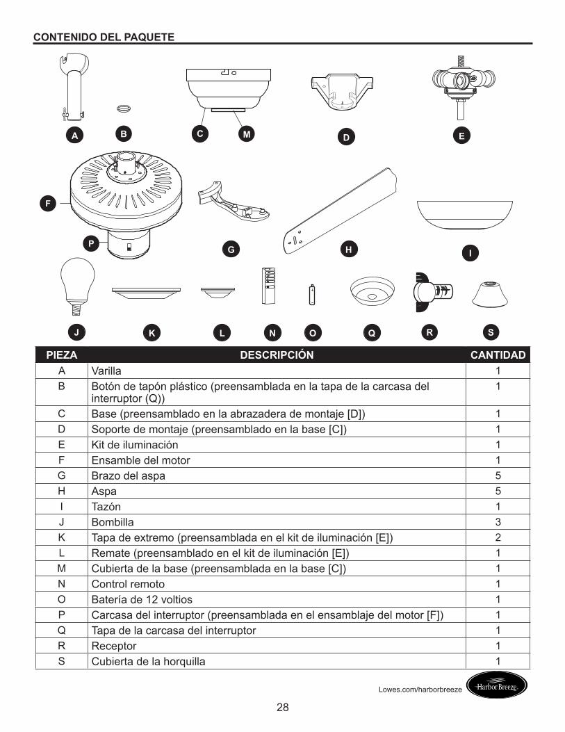
CONTENIDO DEL PAQUETE
A
I
O QJ K L
M
N
G
C
H
D E
F
P
R
B
S
PIEZA DESCRIPCIÓN CANTIDADA Varilla 1B Botón de tapón plástico (preensamblada en la tapa de la carcasa del
interruptor (Q))1
C Base (preensamblado en la abrazadera de montaje [D]) 1D Soporte de montaje (preensamblado en la base [C]) 1E Kit de iluminación 1F Ensamble del motor 1G Brazo del aspa 5H Aspa 5I Tazón 1J Bombilla 3K Tapa de extremo (preensamblada en el kit de iluminación [E]) 2L Remate (preensamblado en el kit de iluminación [E]) 1M Cubierta de la base (preensamblada en la base [C]) 1N Control remoto 1O Batería de 12 voltios 1P Carcasa del interruptor (preensamblada en el ensamblaje del motor [F]) 1Q Tapa de la carcasa del interruptor 1R Receptor 1S Cubierta de la horquilla 1
29
Lowes.com/harborbreeze
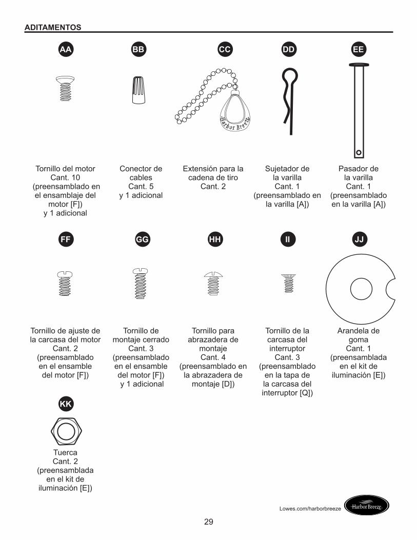
ADITAMENTOS
Tornillo del motor Cant. 10
(preensamblado en el ensamblaje del
motor [F])y 1 adicional
Conector de cables Cant. 5
y 1 adicional
Extensión para la cadena de tiro
Cant. 2
Sujetador de la varillaCant. 1
(preensamblado en la varilla [A])
Pasador de la varilla Cant. 1
(preensamblado en la varilla [A])
Tornillo de ajuste de la carcasa del motor
Cant. 2 (preensamblado en el ensamble del motor [F])
Tornillo de montaje cerrado
Cant. 3(preensamblado en el ensamble del motor [F]) y 1 adicional
Tornillo para abrazadera de
montaje Cant. 4
(preensamblado en la abrazadera de
montaje [D])
Tornillo de la carcasa del interruptor
Cant. 3 (preensamblado
en la tapa de la carcasa del interruptor [Q])
Arandela de goma
Cant. 1 (preensamblada
en el kit de iluminación [E])
Tuerca Cant. 2
(preensamblada en el kit de
iluminación [E])
AA BB CC DD EE
FF
KK
GG HH II JJ
30
Lowes.com/harborbreeze
INFORMACIÓN DE SEGURIDADLea y comprenda completamente este manual antes de intentar ensamblar, usar o instalar el producto.• Antes de comenzar a instalar el ventilador, desconecte la alimentación eléctrica; para esto retire los
fusibles o coloque el interruptor de circuito en la posición de apagado.• Asegúrese de que todas las conexiones eléctricas cumplan con los códigos y ordenanzas locales, el
National Electrical Code (Código Nacional de Electricidad) y la norma ANSI/NFPA 70-199. Si no está familiarizado con la instalación del cableado eléctrico, contrate a un electricista calificado o consulte un manual de cableado para hacerlo usted mismo.
• Asegúrese de que en el lugar de instalación que elija se pueda establecer una distancia mínima de 2,13 m desde las aspas hasta el piso, y al menos 76,20 cm desde los extremos de las aspas hasta cualquier obstáculo.
• El peso neto de este ventilador es: 8 kg.
PELIGRO: Si utiliza una caja de salida existente, asegúrese de que esté bien sujeta a la estructura del edificio y que pueda sostener el peso del ventilador. El incumplimiento de dicho paso podría provocar lesiones graves o la muerte. La estabilidad de la caja de salida es fundamental para minimizar el tambaleo y el ruido en el ventilador una vez que la instalación esté completa.
ADVERTENCIA: Para evitar lesiones personales, puede ser necesario usar guantes al manipular las piezas del ventilador con bordes filosos.
ADVERTENCIA: El uso de un regulador de intensidad de rango completo para controlar la velocidad del ventilador provocará un zumbido intenso del ventilador. Para reducir el riesgo de incendios o descargas eléctricas, NO use un regulador de intensidad de rango completo para controlar la velocidad del ventilador.
ADVERTENCIA: Para reducir el riesgo de incendios, descargas eléctricas o lesiones personales, instale el ventilador en una caja de salida marcada como “APTA PARA SOSTENER UN VENTILADOR” y utilice los tornillos de montaje incluidos en la caja de salida. La mayoría de las cajas de salida que se usan comúnmente para sostener ensambles de iluminación no son aptas para sostener un ventilador y puede ser necesario reemplazarlas. Si tiene dudas, consulte a un electricista calificado. Asegure la caja de salida directamente a la estructura del edificio. La caja de salida y su soporte deben ser capaces de sostener el peso del ventilador en movimiento (al menos 15,88 kg). NO use una caja de salida de plástico.
ADVERTENCIA: Para reducir el riesgo de incendios, descargas eléctricas o lesiones personales, los conectores de cables proporcionados con este ventilador están diseñados para soportar solo un cable de la casa de calibre 12 y dos cables conductores del ventilador. Si el cable de su casa es de un calibre superior a 12 o hay más de un cable para conectar los dos cables conductores del ventilador, pregúntele a un electricista cuál es el tamaño adecuado de los conectores de cables que debe utilizar.
ADVERTENCIA: Para reducir el riesgo de incendios o descargas eléctricas, no use el ventilador con dispositivos de control de velocidad para estado sólido ni controle la velocidad del ventilador con un regulador de intensidad de rango completo.
ADVERTENCIA: Para reducir el riesgo de incendios, descargas eléctricas o lesiones personales, no doble los brazos de las aspas al instalarlas, al equilibrarlas o al limpiar el ventilador. No introduzca objetos entre las aspas en movimiento.
ADVERTENCIA: Para reducir el riesgo de lesiones personales, use sólo las piezas que se incluyen con este ventilador. El uso de piezas DISTINTAS a aquellas que se incluyen con este ventilador anulará la garantía.
31
Lowes.com/harborbreeze
INFORMACIÓN DE SEGURIDADPRECAUCIÓN: Lea todas las instrucciones y la información de seguridad antes de instalar el nuevo ventilador. Revise los diagramas de ensamblaje adjuntos.
PRECAUCIÓN: asegúrese de que la caja de salida cuente con la puesta a tierra adecuada o de que haya un conductor (verde o desnudo) de tierra.
PRECAUCIÓN: Revise cuidadosamente todos los tornillos, pernos y tuercas del ensamble del motor del ventilador para comprobar que estén seguros.
PRECAUCIÓN: Este equipo se probó y se verificó que cumple las normas de un dispositivo digital clase B, conforme a la Sección 15 de las reglas de la FCC. Estas normas se diseñaron para proporcionar una protección razonable contra la interferencia perjudicial en una instalación residencial. Este equipo genera, utiliza y puede irradiar energía de radiofrecuencia y, si no se instala y usa de acuerdo con las instrucciones, puede causar interferencia perjudicial a las comunicaciones de radio.
PREPARACIÓN
Antes de comenzar a ensamblar este producto, asegúrese de tener todas las piezas. Compare todas las piezas con la lista del contenido del paquete y con la lista de aditamentos. No intente ensamblar el producto si falta alguna pieza o si estas están dañadas.
Después de abrir la parte superior de la caja, retire el paquete de aditamentos para montaje de los accesorios de espuma. Luego, quite el motor del ensamble y colóquelo en una superficie suave, como una alfombra, para evitar dañar el acabado.
Tiempo estimado de ensamblaje: 120 minutos
Herramientas necesarias para el ensamblaje (no se incluyen): cinta aislante, destornillador Phillips, pinzas, gafas de seguridad, escalera de tijera y pinzas pelacables.
Herramientas útiles (no se incluyen): Luz de prueba de CA, cinta métrica, manual de cableado y pinzas cortacables
32
Lowes.com/harborbreeze
INSTALACIÓN INICIAL
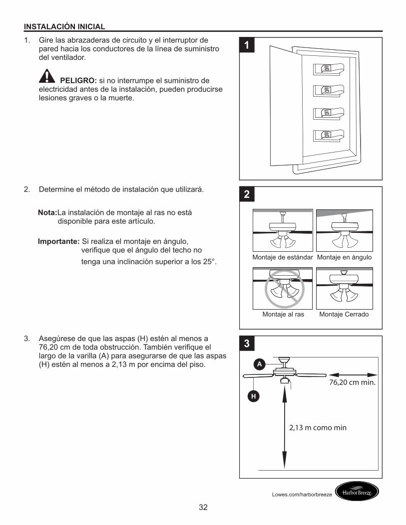
1. Gire las abrazaderas de circuito y el interruptor de pared hacia los conductores de la línea de suministro del ventilador.
PELIGRO: si no interrumpe el suministro de electricidad antes de la instalación, pueden producirse lesiones graves o la muerte.
1
2. Determine el método de instalación que utilizará.
Nota:� La instalación de montaje al ras no está disponible para este artículo.
Importante:� Si realiza el montaje en ángulo, verifique que el ángulo del techo no tenga una inclinación superior a los 25°.
2
Montaje de estándar
Montaje al ras Montaje Cerrado
Montaje en ángulo
3. Asegúrese de que las aspas (H) estén al menos a 76,20 cm de toda obstrucción. También verifique el largo de la varilla (A) para asegurarse de que las aspas (H) estén al menos a 2,13 m por encima del piso. A
H
3
2,13 m como min
76,20 cm min.
33
Lowes.com/harborbreeze
INSTALACIÓN INICIAL
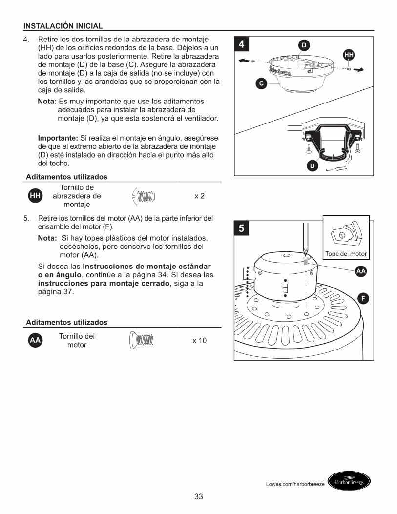
4. Retire los dos tornillos de la abrazadera de montaje (HH) de los orificios redondos de la base. Déjelos a un lado para usarlos posteriormente. Retire la abrazadera de montaje (D) de la base (C). Asegure la abrazadera de montaje (D) a la caja de salida (no se incluye) con los tornillos y las arandelas que se proporcionan con la caja de salida.Nota:� Es muy importante que use los aditamentos
adecuados para instalar la abrazadera de montaje (D), ya que esta sostendrá el ventilador.
Importante:� Si realiza el montaje en ángulo, asegúrese de que el extremo abierto de la abrazadera de montaje (D) esté instalado en dirección hacia el punto más alto del techo.
Aditamentos utilizados
HHTornillo de
abrazadera de montaje
x 2
D
4
C
HHD
5. Retire los tornillos del motor (AA) de la parte inferior del ensamble del motor (F).Nota:� Si hay topes plásticos del motor instalados,
deséchelos, pero conserve los tornillos del motor (AA).
Aditamentos utilizados
AA Tornillo del motor x 10
AA
F
5
Tope del motor
Si desea las Instrucciones de montaje estándar o en ángulo, continúe a la página 34. Si desea las instrucciones para montaje cerrado, siga a la página 37.
34
Lowes.com/harborbreeze
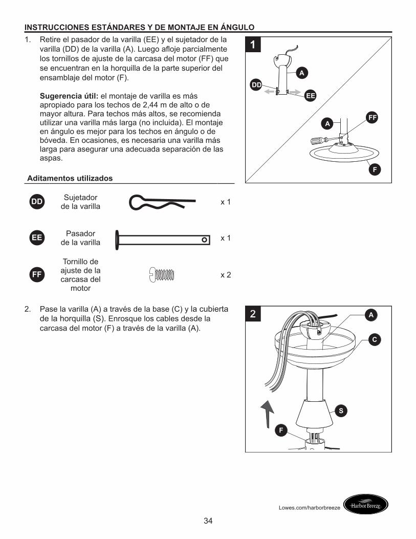
INSTRUCCIONES ESTÁNDARES Y DE MONTAJE EN ÁNGULO1. Retire el pasador de la varilla (EE) y el sujetador de la
varilla (DD) de la varilla (A). Luego afloje parcialmente los tornillos de ajuste de la carcasa del motor (FF) que se encuentran en la horquilla de la parte superior del ensamblaje del motor (F).
Sugerencia útil: el montaje de varilla es más apropiado para los techos de 2,44 m de alto o de mayor altura. Para techos más altos, se recomienda utilizar una varilla más larga (no incluida). El montaje en ángulo es mejor para los techos en ángulo o de bóveda. En ocasiones, es necesaria una varilla más larga para asegurar una adecuada separación de las aspas.
Aditamentos utilizados
DD Sujetador de la varilla x 1
EE Pasador de la varilla x 1
FFTornillo de
ajuste de la carcasa del
motor
x 2
F
A
DDEE
FFA
1
2. Pase la varilla (A) a través de la base (C) y la cubierta de la horquilla (S). Enrosque los cables desde la carcasa del motor (F) a través de la varilla (A).
A
C
S
F
2
35
Lowes.com/harborbreeze
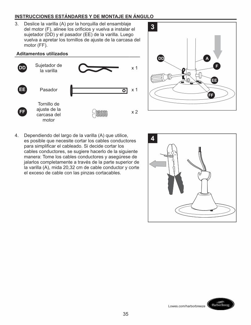
INSTRUCCIONES ESTÁNDARES Y DE MONTAJE EN ÁNGULO3. Deslice la varilla (A) por la horquilla del ensamblaje
del motor (F), alinee los orificios y vuelva a instalar el sujetador (DD) y el pasador (EE) de la varilla. Luego vuelva a apretar los tornillos de ajuste de la carcasa del motor (FF).
Aditamentos utilizados
DD Sujetador de la varilla x 1
EE Pasador x 1
FFTornillo de
ajuste de la carcasa del
motor
x 2
DD
FF
A
F
EE
3
4. Dependiendo del largo de la varilla (A) que utilice, es posible que necesite cortar los cables conductores para simplificar el cableado. Si decide cortar los cables conductores, se sugiere hacerlo de la siguiente manera: Tome los cables conductores y asegúrese de jalarlos completamente a través de la parte superior de la varilla (A), mida 20,32 cm de cable conductor y corte el exceso de cable con las pinzas cortacables.
4
36
Lowes.com/harborbreeze
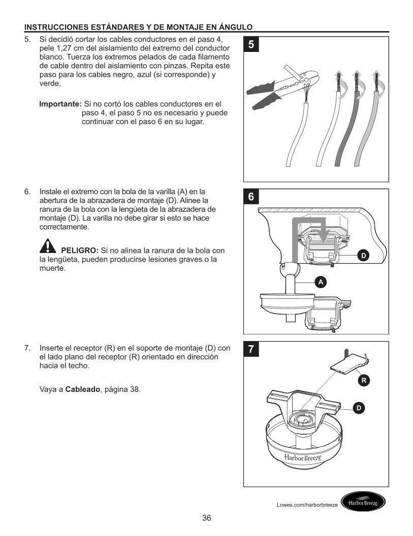
INSTRUCCIONES ESTÁNDARES Y DE MONTAJE EN ÁNGULO5. Si decidió cortar los cables conductores en el paso 4,
pele 1,27 cm del aislamiento del extremo del conductor blanco. Tuerza los extremos pelados de cada filamento de cable dentro del aislamiento con pinzas. Repita este paso para los cables negro, azul (si corresponde) y verde.
Importante:� Si no cortó los cables conductores en el paso 4, el paso 5 no es necesario y puede continuar con el paso 6 en su lugar.
5
6. Instale el extremo con la bola de la varilla (A) en la abertura de la abrazadera de montaje (D). Alinee la ranura de la bola con la lengüeta de la abrazadera de montaje (D). La varilla no debe girar si esto se hace correctamente.
PELIGRO: Si no alinea la ranura de la bola con la lengüeta, pueden producirse lesiones graves o la muerte.
7. Inserte el receptor (R) en el soporte de montaje (D) con el lado plano del receptor (R) orientado en dirección hacia el techo.
Vaya a Cableado, página 38.
D
A
6
D
R
7
37
Lowes.com/harborbreeze
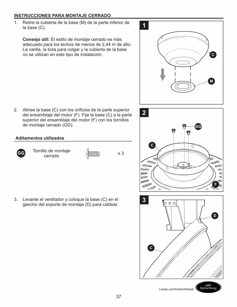
INSTRUCCIONES PARA MONTAJE CERRADO1. Retire la cubierta de la base (M) de la parte inferior de
la base (C).
Consejo útil: El estilo de montaje cerrado es más adecuado para los techos de menos de 2,44 m de alto. La varilla, la bola para colgar y la cubierta de la base no se utilizan en este tipo de instalación.
1
M
C
2. Alinee la base (C) con los orificios de la parte superior del ensamblaje del motor (F). Fije la base (C) a la parte superior del ensamblaje del motor (F) con los tornillos de montaje cerrado (GG).
Aditamentos utilizados
GG Tornillo de montaje cerrado x 3
3. Levante el ventilador y coloque la base (C) en el gancho del soporte de montaje (D) para cablear.
C
D
3
F
C
GG
2
38
Lowes.com/harborbreeze
CABLEADO
ADVERTENCIA: para reducir el riesgo de incendios, descargas eléctricas o lesiones personales, los conectores de cables proporcionados con este ventilador están diseñados para soportar solo un cable de la casa de calibre 12 y dos cables conductores del ventilador. Si el cable interior es de un calibre superior a 12 o hay más de un cable interior para conectar los dos cables conductores del ventilador, pregúntele a un electricista cuál es el tamaño adecuado de los conectores de cables que debe utilizar.
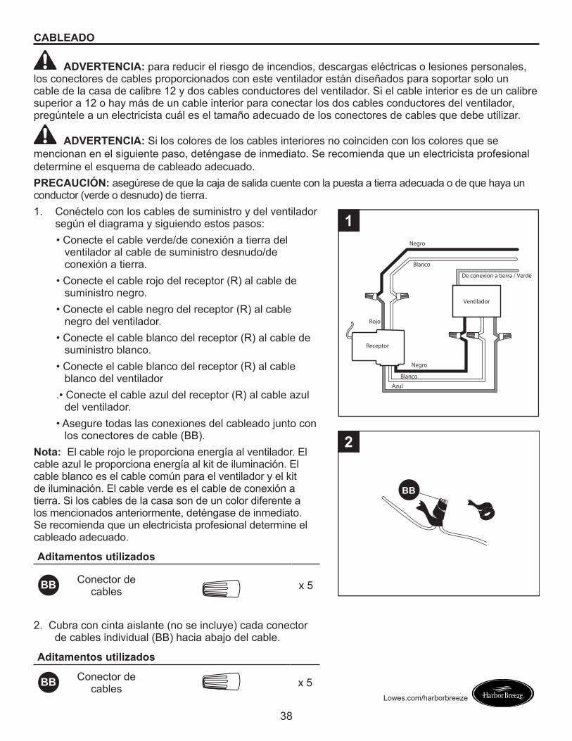
ADVERTENCIA: Si los colores de los cables interiores no coinciden con los colores que se mencionan en el siguiente paso, deténgase de inmediato. Se recomienda que un electricista profesional determine el esquema de cableado adecuado.PRECAUCIÓN: asegúrese de que la caja de salida cuente con la puesta a tierra adecuada o de que haya un conductor (verde o desnudo) de tierra.1. Conéctelo con los cables de suministro y del ventilador
según el diagrama y siguiendo estos pasos:• Conecte el cable verde/de conexión a tierra del
ventilador al cable de suministro desnudo/de conexión a tierra.
• Conecte el cable rojo del receptor (R) al cable de suministro negro.
• Conecte el cable negro del receptor (R) al cable negro del ventilador.
• Conecte el cable blanco del receptor (R) al cable de suministro blanco.
• Conecte el cable blanco del receptor (R) al cable blanco del ventilador
.• Conecte el cable azul del receptor (R) al cable azul del ventilador.
• Asegure todas las conexiones del cableado junto con los conectores de cable (BB).
Nota: El cable rojo le proporciona energía al ventilador. El cable azul le proporciona energía al kit de iluminación. El cable blanco es el cable común para el ventilador y el kit de iluminación. El cable verde es el cable de conexión a tierra. Si los cables de la casa son de un color diferente a los mencionados anteriormente, deténgase de inmediato. Se recomienda que un electricista profesional determine el cableado adecuado.
Aditamentos utilizados
BB Conector de cables x 5
Receptor
Ventilador
Negro
Negro
Azul
Blanco
De conexion a tierra / Verde
Blanco
1
Rojo
BB
2
2. Cubra con cinta aislante (no se incluye) cada conector de cables individual (BB) hacia abajo del cable.
Aditamentos utilizados
BB Conector de cables x 5
39
Lowes.com/harborbreeze
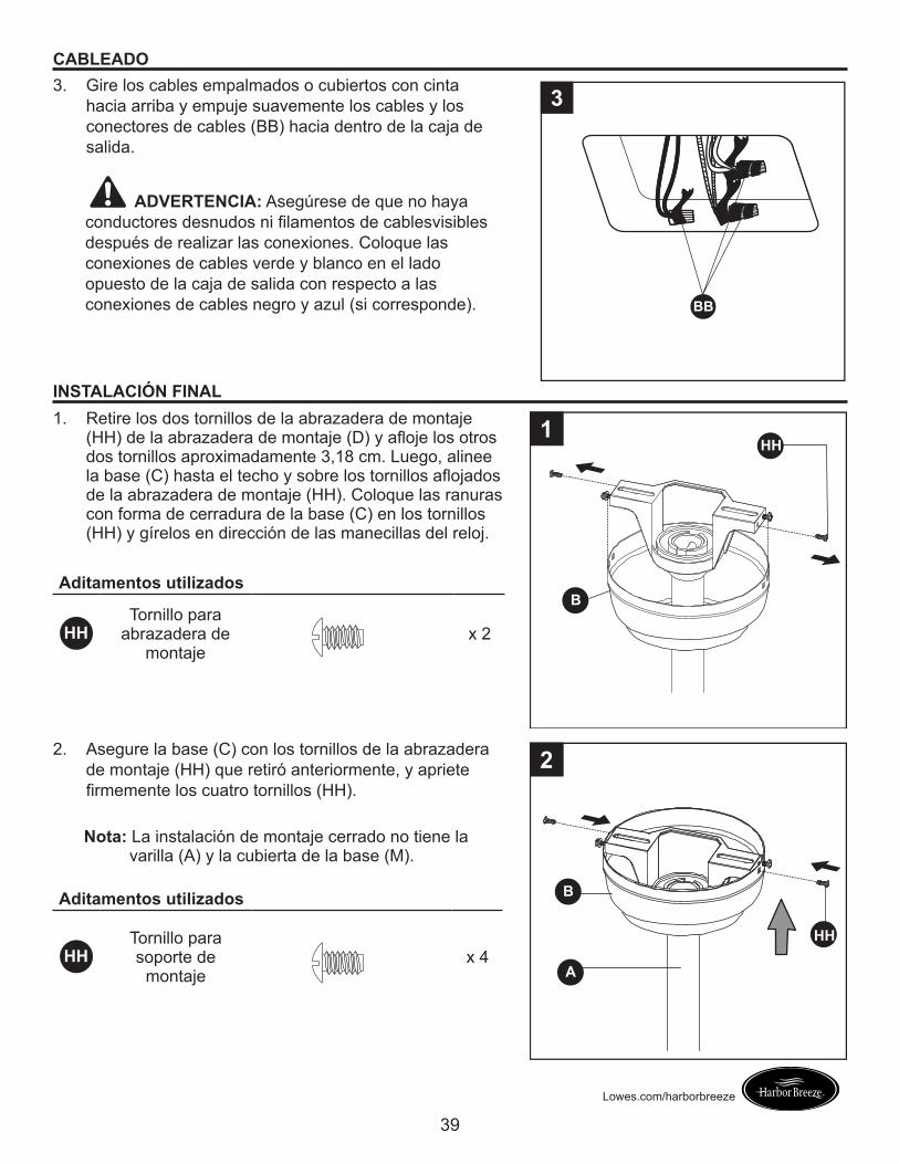
CABLEADO3. Gire los cables empalmados o cubiertos con cinta
hacia arriba y empuje suavemente los cables y los conectores de cables (BB) hacia dentro de la caja de salida.
ADVERTENCIA: Asegúrese de que no haya conductores desnudos ni filamentos de cablesvisibles después de realizar las conexiones. Coloque las conexiones de cables verde y blanco en el lado opuesto de la caja de salida con respecto a las conexiones de cables negro y azul (si corresponde). BB
3
INSTALACIÓN FINAL1. Retire los dos tornillos de la abrazadera de montaje
(HH) de la abrazadera de montaje (D) y afloje los otros dos tornillos aproximadamente 3,18 cm. Luego, alinee la base (C) hasta el techo y sobre los tornillos aflojados de la abrazadera de montaje (HH). Coloque las ranuras con forma de cerradura de la base (C) en los tornillos (HH) y gírelos en dirección de las manecillas del reloj.
Aditamentos utilizados
HHTornillo para
abrazadera de montaje
x 2
B
HH1
2. Asegure la base (C) con los tornillos de la abrazadera de montaje (HH) que retiró anteriormente, y apriete firmemente los cuatro tornillos (HH).
Nota:� La instalación de montaje cerrado no tiene la varilla (A) y la cubierta de la base (M).
Aditamentos utilizados
HHTornillo para soporte de
montajex 4
B
J
HH
A
II
2
40
Lowes.com/harborbreeze
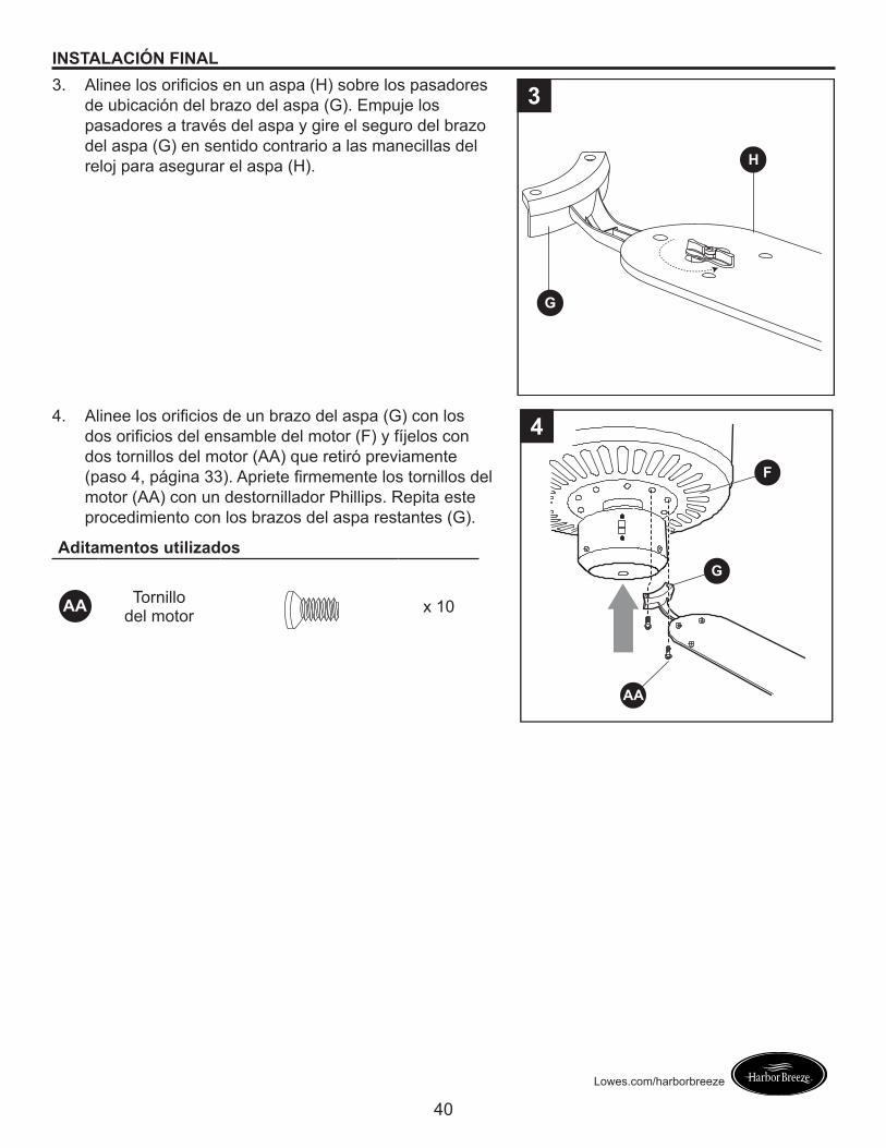
INSTALACIÓN FINAL3. Alinee los orificios en un aspa (H) sobre los pasadores
de ubicación del brazo del aspa (G). Empuje los pasadores a través del aspa y gire el seguro del brazo del aspa (G) en sentido contrario a las manecillas del reloj para asegurar el aspa (H).
3
G
H
4. Alinee los orificios de un brazo del aspa (G) con los dos orificios del ensamble del motor (F) y fíjelos con dos tornillos del motor (AA) que retiró previamente (paso 4, página 33). Apriete firmemente los tornillos del motor (AA) con un destornillador Phillips. Repita este procedimiento con los brazos del aspa restantes (G).
Aditamentos utilizados
AA Tornillo del motor x 10
4
AA
F
G
41
Lowes.com/harborbreeze
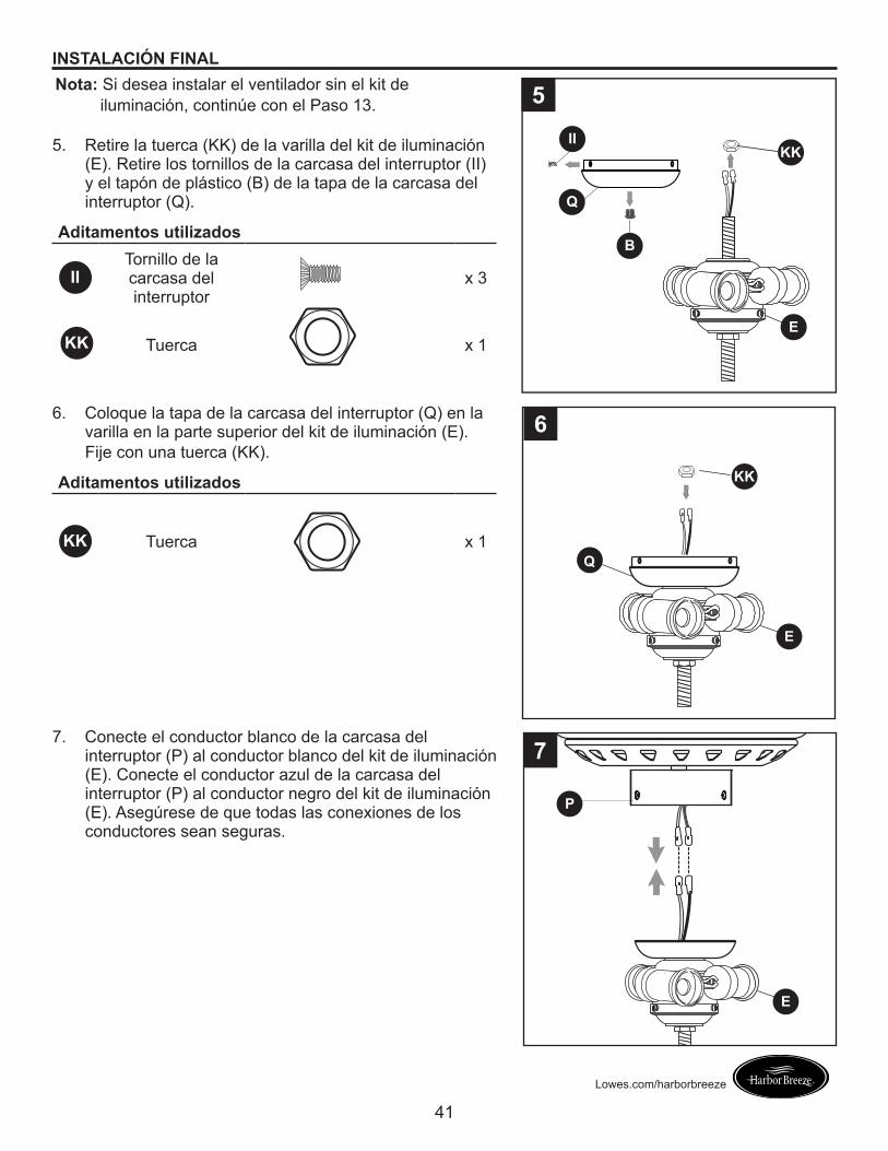
INSTALACIÓN FINALNota:� Si desea instalar el ventilador sin el kit de
iluminación, continúe con el Paso 13.
5. Retire la tuerca (KK) de la varilla del kit de iluminación (E). Retire los tornillos de la carcasa del interruptor (II) y el tapón de plástico (B) de la tapa de la carcasa del interruptor (Q).
Aditamentos utilizados
IITornillo de la carcasa del interruptor
x 3
Tuerca x 1
5
E
KK
Q
B
II
6. Coloque la tapa de la carcasa del interruptor (Q) en la varilla en la parte superior del kit de iluminación (E). Fije con una tuerca (KK).
Aditamentos utilizados
KK Tuerca x 1
7. Conecte el conductor blanco de la carcasa del interruptor (P) al conductor blanco del kit de iluminación (E). Conecte el conductor azul de la carcasa del interruptor (P) al conductor negro del kit de iluminación (E). Asegúrese de que todas las conexiones de los conductores sean seguras.
P
E
7
6
Q
E
KK
KK
42
Lowes.com/harborbreeze
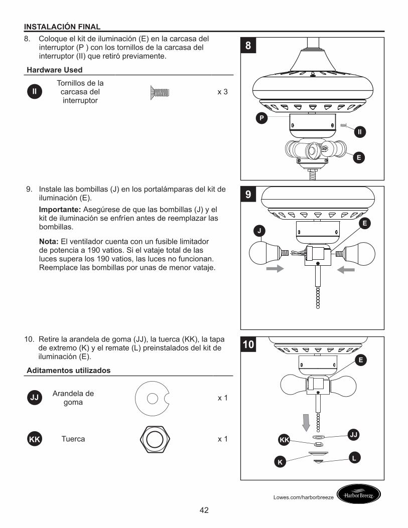
INSTALACIÓN FINAL8. Coloque el kit de iluminación (E) en la carcasa del
interruptor (P ) con los tornillos de la carcasa del interruptor (II) que retiró previamente.
Hardware Used
IITornillos de la carcasa del interruptor
x 3
P
E
II
8
9. Instale las bombillas (J) en los portalámparas del kit de iluminación (E).
Importante: Asegúrese de que las bombillas (J) y el kit de iluminación se enfríen antes de reemplazar las bombillas.
Nota: El ventilador cuenta con un fusible limitador de potencia a 190 vatios. Si el vataje total de las luces supera los 190 vatios, las luces no funcionan. Reemplace las bombillas por unas de menor vataje.
EJ
9
10. Retire la arandela de goma (JJ), la tuerca (KK), la tapa de extremo (K) y el remate (L) preinstalados del kit de iluminación (E).
Aditamentos utilizados
JJ Arandela de goma x 1
KK Tuerca x 1
E
10
K L
JJKK
43
Lowes.com/harborbreeze
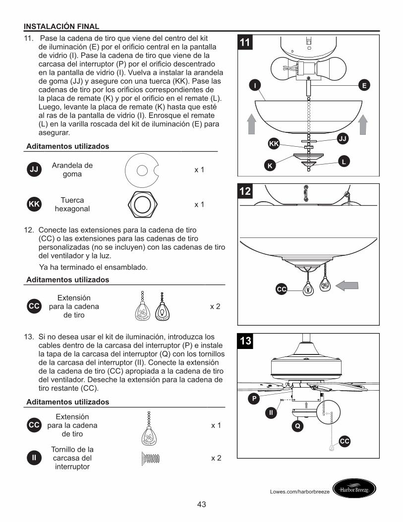
INSTALACIÓN FINAL11. Pase la cadena de tiro que viene del centro del kit
de iluminación (E) por el orificio central en la pantalla de vidrio (I). Pase la cadena de tiro que viene de la carcasa del interruptor (P) por el orificio descentrado en la pantalla de vidrio (I). Vuelva a instalar la arandela de goma (JJ) y asegure con una tuerca (KK). Pase las cadenas de tiro por los orificios correspondientes de la placa de remate (K) y por el orificio en el remate (L). Luego, levante la placa de remate (K) hasta que esté al ras de la pantalla de vidrio (I). Enrosque el remate (L) en la varilla roscada del kit de iluminación (E) para asegurar.
Aditamentos utilizados
JJ Arandela de goma x 1
KK Tuerca hexagonal x 1
12. Conecte las extensiones para la cadena de tiro (CC) o las extensiones para las cadenas de tiro personalizadas (no se incluyen) con las cadenas de tiro del ventilador y la luz.
Ya ha terminado el ensamblado.
13. Si no desea usar el kit de iluminación, introduzca los cables dentro de la carcasa del interruptor (P) e instale la tapa de la carcasa del interruptor (Q) con los tornillos de la carcasa del interruptor (II). Conecte la extensión de la cadena de tiro (CC) apropiada a la cadena de tiro del ventilador. Deseche la extensión para la cadena de tiro restante (CC).
Aditamentos utilizados
CCExtensión
para la cadena de tiro
x 1
IITornillo de la carcasa del interruptor
x 2
I E
K L
JJKK
11
12
CCAditamentos utilizados
CCExtensión
para la cadena de tiro
x 2
H
arbor
Breeze
H
arbor Breeze
H
arbor Breeze
P
Q
CC
II
H
arbor Breeze
13
44
Lowes.com/harborbreeze
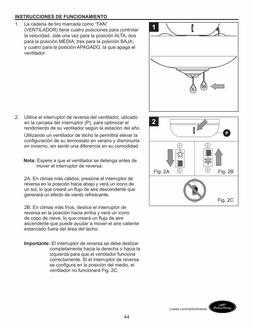
INSTRUCCIONES DE FUNCIONAMIENTO1. La cadena de tiro marcada como “FAN”
(VENTILADOR) tiene cuatro posiciones para controlar la velocidad. Jale una vez para la posición ALTA; dos para la posición MEDIA; tres para la posición BAJA; y cuatro para la posición APAGADO, la que apaga el ventilador.
1
2. Utilice el interruptor de reversa del ventilador, ubicado en la carcasa del interruptor (P), para optimizar el rendimiento de su ventilador según la estación del año.Utilizando un ventilador de techo le permitirá elevar la configuración de su termostato en verano y disminuirla en invierno, sin sentir una diferencia en su comodidad.
Nota:� Espere a que el ventilador se detenga antes de mover el interruptor de reversa.
2A. En climas más cálidos, presione el interruptor de reversa en la posición hacia abajo y verá un icono de un sol, lo que creará un flujo de aire descendente que generará un efecto de viento refrescante.
2B. En climas más fríos, deslice el interruptor de reversa en la posición hacia arriba y verá un icono de copo de nieve, lo que creará un flujo de aire ascendente que puede ayudar a mover el aire caliente estancado fuera del área del techo.
Importante:� El interruptor de reversa se debe deslizar completamente hacia la derecha o hacia la izquierda para que el ventilador funcione correctamente. Si el interruptor de reversa se configura en la posición del medio, el ventilador no funcionará Fig. 2C.
Fig. 2A Fig. 2B
Fig. 2C
P
2
45
Lowes.com/harborbreeze
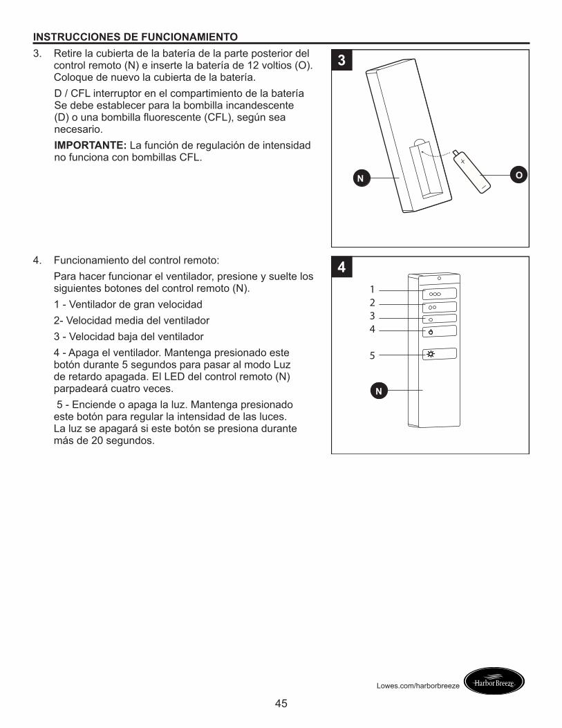
INSTRUCCIONES DE FUNCIONAMIENTO3. Retire la cubierta de la batería de la parte posterior del
control remoto (N) e inserte la batería de 12 voltios (O). Coloque de nuevo la cubierta de la batería.D / CFL interruptor en el compartimiento de la batería Se debe establecer para la bombilla incandescente (D) o una bombilla fluorescente (CFL), según sea necesario.IMPORTANTE: La función de regulación de intensidad no funciona con bombillas CFL.
N O
O P
3
4. Funcionamiento del control remoto:Para hacer funcionar el ventilador, presione y suelte los siguientes botones del control remoto (N). 1 - Ventilador de gran velocidad2- Velocidad media del ventilador3 - Velocidad baja del ventilador4 - Apaga el ventilador. Mantenga presionado este botón durante 5 segundos para pasar al modo Luz de retardo apagada. El LED del control remoto (N) parpadeará cuatro veces. 5 - Enciende o apaga la luz. Mantenga presionado este botón para regular la intensidad de las luces. La luz se apagará si este botón se presiona durante más de 20 segundos.
N
O P
1234
5
4
46
Lowes.com/harborbreeze
CUIDADO Y MANTENIMIENTO
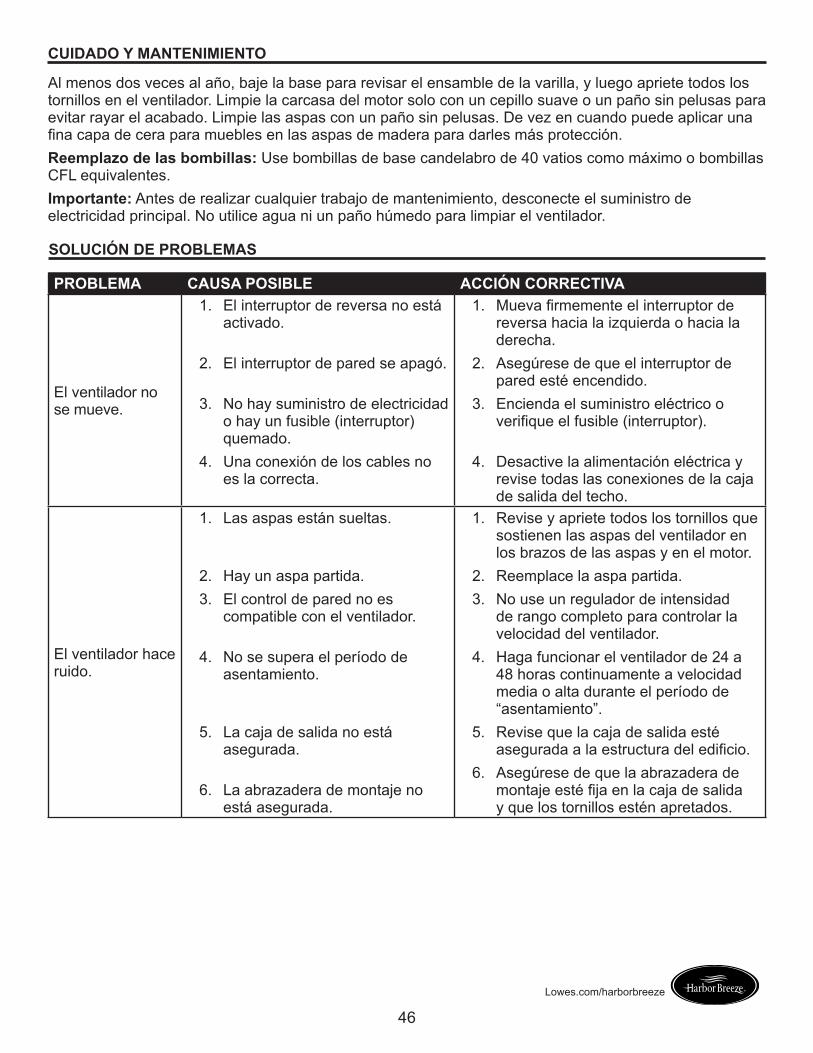
Al menos dos veces al año, baje la base para revisar el ensamble de la varilla, y luego apriete todos los tornillos en el ventilador. Limpie la carcasa del motor solo con un cepillo suave o un paño sin pelusas para evitar rayar el acabado. Limpie las aspas con un paño sin pelusas. De vez en cuando puede aplicar una fina capa de cera para muebles en las aspas de madera para darles más protección. Reemplazo de las bombillas: Use bombillas de base candelabro de 40 vatios como máximo o bombillas CFL equivalentes.Importante:� Antes de realizar cualquier trabajo de mantenimiento, desconecte el suministro de electricidad principal. No utilice agua ni un paño húmedo para limpiar el ventilador. SOLUCIÓN DE PROBLEMAS
PROBLEMA CAUSA POSIBLE ACCIÓN CORRECTIVA
El ventilador no se mueve.
1. El interruptor de reversa no está activado.
2. El interruptor de pared se apagó.
3. No hay suministro de electricidad o hay un fusible (interruptor) quemado.
4. Una conexión de los cables no es la correcta.
1. Mueva firmemente el interruptor de reversa hacia la izquierda o hacia la derecha.
2. Asegúrese de que el interruptor de pared esté encendido.
3. Encienda el suministro eléctrico o verifique el fusible (interruptor).
4. Desactive la alimentación eléctrica y revise todas las conexiones de la caja de salida del techo.
El ventilador hace ruido.
1. Las aspas están sueltas.
2. Hay un aspa partida.3. El control de pared no es
compatible con el ventilador.
4. No se supera el período de asentamiento.
5. La caja de salida no está asegurada.
6. La abrazadera de montaje no está asegurada.
1. Revise y apriete todos los tornillos que sostienen las aspas del ventilador en los brazos de las aspas y en el motor.
2. Reemplace la aspa partida.3. No use un regulador de intensidad
de rango completo para controlar la velocidad del ventilador.
4. Haga funcionar el ventilador de 24 a 48 horas continuamente a velocidad media o alta durante el período de “asentamiento”.
5. Revise que la caja de salida esté asegurada a la estructura del edificio.
6. Asegúrese de que la abrazadera de montaje esté fija en la caja de salida y que los tornillos estén apretados.
47
Lowes.com/harborbreeze
SOLUCIÓN DE PROBLEMAS
PROBLEMA CAUSA POSIBLE ACCIÓN CORRECTIVA
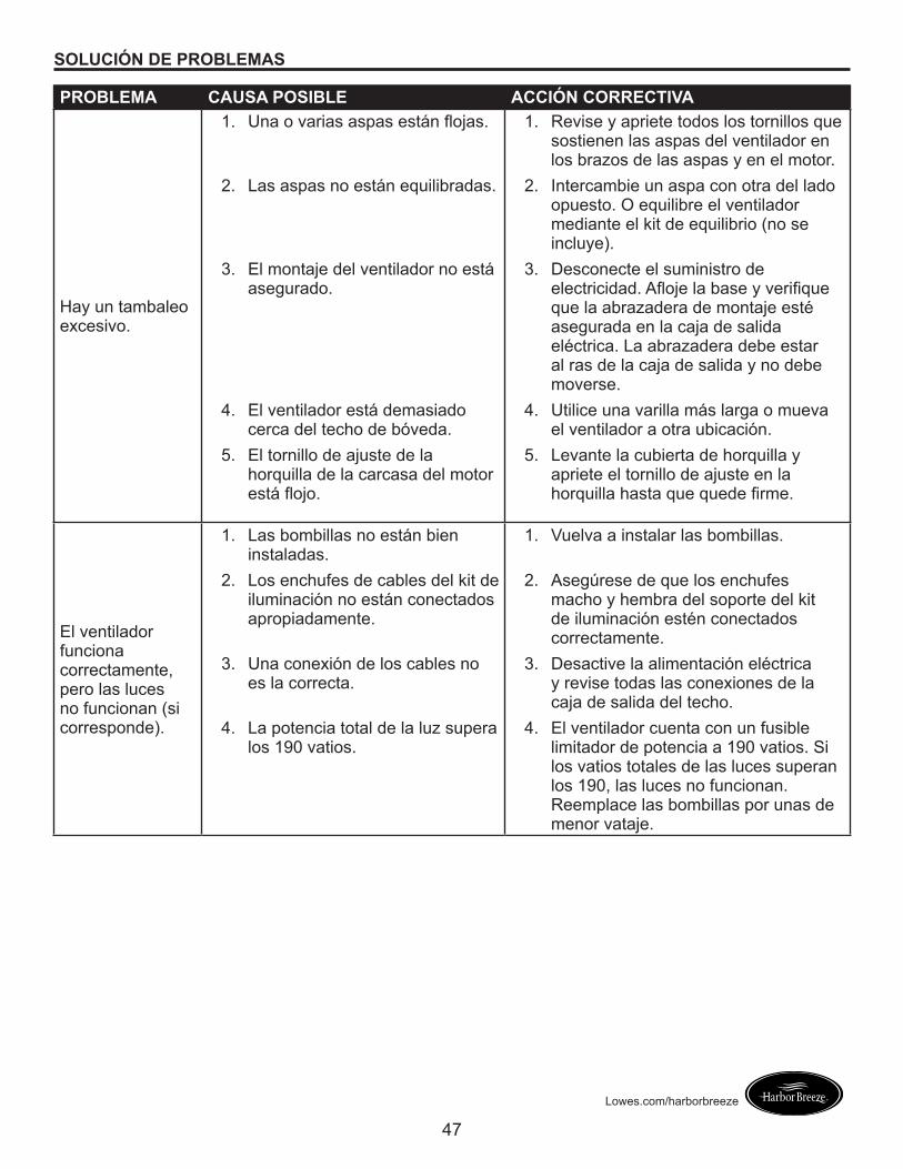
Hay un tambaleo excesivo.
1. Una o varias aspas están flojas.
2. Las aspas no están equilibradas.
3. El montaje del ventilador no está asegurado.
4. El ventilador está demasiado cerca del techo de bóveda.
5. El tornillo de ajuste de la horquilla de la carcasa del motor está flojo.
1. Revise y apriete todos los tornillos que sostienen las aspas del ventilador en los brazos de las aspas y en el motor.
2. Intercambie un aspa con otra del lado opuesto. O equilibre el ventilador mediante el kit de equilibrio (no se incluye).
3. Desconecte el suministro de electricidad. Afloje la base y verifique que la abrazadera de montaje esté asegurada en la caja de salida eléctrica. La abrazadera debe estar al ras de la caja de salida y no debe moverse.
4. Utilice una varilla más larga o mueva el ventilador a otra ubicación.
5. Levante la cubierta de horquilla y apriete el tornillo de ajuste en la horquilla hasta que quede firme.
El ventilador funciona correctamente, pero las luces no funcionan (si corresponde).
1. Las bombillas no están bien instaladas.
2. Los enchufes de cables del kit de iluminación no están conectados apropiadamente.
3. Una conexión de los cables no es la correcta.
4. La potencia total de la luz supera los 190 vatios.
1. Vuelva a instalar las bombillas.
2. Asegúrese de que los enchufes macho y hembra del soporte del kit de iluminación estén conectados correctamente.
3. Desactive la alimentación eléctrica y revise todas las conexiones de la caja de salida del techo.
4. El ventilador cuenta con un fusible limitador de potencia a 190 vatios. Si los vatios totales de las luces superan los 190, las luces no funcionan. Reemplace las bombillas por unas de menor vataje.
48
Lowes.com/harborbreeze
GARANTÍA LIMITADA DE POR VIDA
El fabricante garantiza que este ventilador no presenta defectos de mano de obra ni de materiales en el momento del transporte desde la fábrica durante un período de por vida a partir de la fecha de compra del comprador original. El comercio minorista también garantiza que las demás piezas del ventilador, con excepción de cualquier aspa de vidrio o plexiglás, no presentan defectos de mano de obra ni de materiales en el momento del transporte desde la fábrica, durante un período de un año a partir de la fecha de compra por parte del comprador original. El fabricante acepta reparar dichos defectos sin cargo o, a su elección, reemplazar el ventilador de techo por un modelo comparable o superior.Para obtener el servicio de garantía, presente una copia del recibo como comprobante de la compra. Todos los costos de retiro y reinstalación del producto son su responsabilidad. Esta garantía no se aplica a ningún daño que se produzca en cualquier pieza del producto como consecuencia de un accidente, uso indebido o instalación incorrecta, o causado por elementos accesorios. El fabricante no asume ningún tipo de responsabilidad por la instalación del ventilador durante la garantía limitada de por vida. Cualquier servicio realizado por una persona no autorizada invalidará la garantía.Debido a las cambiantes condiciones climáticas, esta garantía no cubre cambios en el acabado de latón, incluidos la oxidación, las picaduras, la corrosión, el deslustre o el descascarado. Los acabados de latón de este tipo proporcionan una vida útil más prolongada si se los protege de las cambiantes condiciones climáticas. La garantía no cubre los elementos de vidrio incluidos con este ventilador.Cualquier reemplazo de piezas defectuosas para el ventilador de techo debe informarse dentro del primer año posterior a la fecha de compra. Para conocer el saldo de la garantía, llame a nuestro departamento de servicio al cliente y obtenga la autorización de la devolución e instrucciones de envío de modo que podamos reparar o reemplazar el ventilador de techo. Cualquier ventilador o piezas devueltos de forma incorrecta son responsabilidad única del comprador. No existen otras garantías explícitas. El fabricante rechaza cualquier y todas las garantías. La duración de cualquier garantía implícita que no se pueda rechazar se limita al período de tiempo especificado en la garantía expresa. El fabricante no será responsable por daños incidentales, resultantes o especiales que surjan en relación con el uso o el rendimiento del producto, excepto que la ley indique lo contrario. Esta garantía le otorga derechos legales específicos, pero podría tener, también, otros derechos que varían según el estado.Esta garantía sustituye cualquier garantía previa.Nota:� Un cierto “tambaleo” es normal y no se debe considerar como un defecto.
49
Lowes.com/harborbreeze
Impreso en ChinaHarbor Breeze® es una marca registrada de LF, LLC.
Todos los derechos reservados.
LISTA DE PIEZAS DE REPUESTO
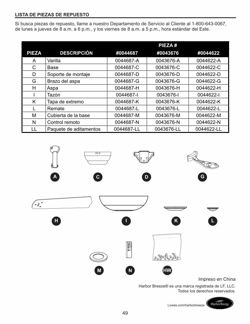
Si busca piezas de repuesto, llame a nuestro Departamento de Servicio al Cliente al 1-800-643-0067, de lunes a jueves de 8 a.m. a 6 p.m., y los viernes de 8 a.m. a 5 p.m., hora estándar del Este.
PIEZA #PIEZA DESCRIPCIÓN #0044687 #0043676 #0044622
A Varilla 0044687-A 0043676-A 0044622-AC Base 0044687-C 0043676-C 0044622-CD Soporte de montaje 0044687-D 0043676-D 0044622-DG Brazo del aspa 0044687-G 0043676-G 0044622-GH Aspa 0044687-H 0043676-H 0044622-HI Tazón 0044687-I 0043676-I 0044622-IK Tapa de extremo 0044687-K 0043676-K 0044622-KL Remate 0044687-L 0043676-L 0044622-LM Cubierta de la base 0044687-M 0043676-M 0044622-MN Control remoto 0044687-N 0043676-N 0044622-NLL Paquete de aditamentos 0044687-LL 0043676-LL 0044622-LL
A
H L
M
C D
I
G
K
HWN