Embed Size (px)
Citation preview

It’s all about the Parison!
Robin Enderby BMC Controls SPE Conference, Detroit 06 A perfectly formed parison is a pre-requisite to producing moldings that have to meet tight specifications such as weight, wall thickness and sur-face finish. Although virtually all modern machines are fitted with ‘conventional’ wall thickness parison programmers there are many other parameters that can be controlled to achieve better results. This paper will investigate the use of profiled push-out speed, dynami-cally deformable die rings and ‘shifting’ dies as a means of achieving better wall thickness control. Manufacturers of Parison programmers continue to add new features and these will also be discussed along with the improvements in the reli-ability of servo valves.

It’s all about the Parison! “Competition has never been so fierce” is probably one of the most common introductory statements made at any plastics conference. Well for processors, this is certainly truer than ever. With profit margins often in single digits, company owners must wonder why they would want to invest $ ½ million in a new machine to make a penny a molding. What can we do about this? One answer is to stop caving in to demands for profitless prices, but that’s easier said than done when you have a bunch of machines standing idle. Another option is to improve efficiency and the efficiency I want to look at today is reducing material usage by optimizing distribution and reducing scrap. The first thought most people have when it comes to material distribution is the parison pro-grammer, but there are a variety of other devices aimed at improving material distribution. Parison programming systems are getting smarter, more reliable and perhaps most importantly, more user-friendly. I would like to propose that the ‘user-friendliness’ of any control system is much more im-portant that most of us actually realize. This is based on the premise that if something is difficult to adjust, then many machine set-ters won’t persevere to find the optimum settings, they will give up when its ‘good enough’. This situation is made worse in companies that have reduced staff to stay competitive, and the emphasis is on getting the machine up and running, not optimizing the best settings. As many will know, the first electronic parison programmer was invented by Denes Hunkar who was a true visionary, and can be credited with introducing many of the features that are found in today’s machine controls. Like many whose ideas were ahead of their time, some of Hunkar’s innovations were actu-ally ridiculed. This of course hasn’t stopped his competitors from quietly sneaking some of Hunkar’s ideas into their products as they finally learn enough about molders needs to see the truth in Denese’s ideas. These early parison programmers had pins or sliders to set the profile and although this might now seem old fashioned, I would maintain that this method of profile adjustment is still the most user-friendly in many applications.
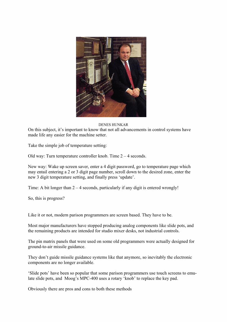
DENES HUNKAR On this subject, it’s important to know that not all advancements in control systems have made life any easier for the machine setter. Take the simple job of temperature setting: Old way: Turn temperature controller knob. Time 2 – 4 seconds. New way: Wake up screen saver, enter a 4 digit password, go to temperature page which may entail entering a 2 or 3 digit page number, scroll down to the desired zone, enter the new 3 digit temperature setting, and finally press ‘update’. Time: A bit longer than 2 – 4 seconds, particularly if any digit is entered wrongly! So, this is progress?
Like it or not, modern parison programmers are screen based. They have to be. Most major manufacturers have stopped producing analog components like slide pots, and the remaining products are intended for studio mixer desks, not industrial controls. The pin matrix panels that were used on some old programmers were actually designed for ground-to-air missile guidance. They don’t guide missile guidance systems like that anymore, so inevitably the electronic components are no longer available. ‘Slide pots’ have been so popular that some parison programmers use touch screens to emu-late slide pots, and Moog’s MPC-400 uses a rotary ‘knob’ to replace the key pad. Obviously there are pros and cons to both these methods
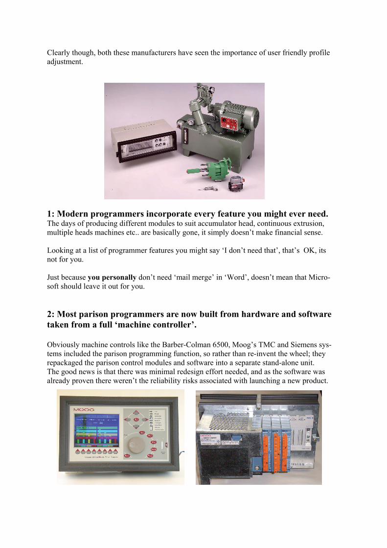
Clearly though, both these manufacturers have seen the importance of user friendly profile adjustment. 1: Modern programmers incorporate every feature you might ever need. The days of producing different modules to suit accumulator head, continuous extrusion, multiple heads machines etc.. are basically gone, it simply doesn’t make financial sense. Looking at a list of programmer features you might say ‘I don’t need that’, that’s OK, its not for you. Just because you personally don’t need ‘mail merge’ in ‘Word’, doesn’t mean that Micro-soft should leave it out for you. 2: Most parison programmers are now built from hardware and software taken from a full ‘machine controller’. Obviously machine controls like the Barber-Colman 6500, Moog’s TMC and Siemens sys-tems included the parison programming function, so rather than re-invent the wheel; they repackaged the parison control modules and software into a separate stand-alone unit. The good news is that there was minimal redesign effort needed, and as the software was already proven there weren’t the reliability risks associated with launching a new product.
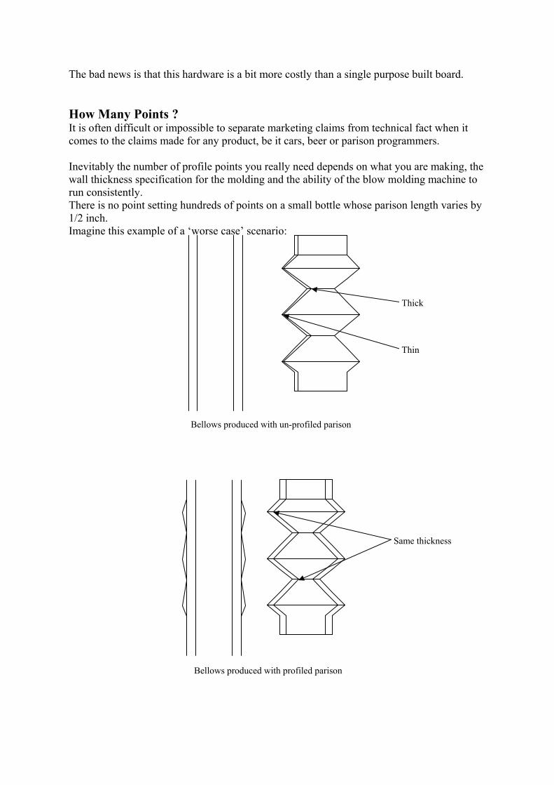
The bad news is that this hardware is a bit more costly than a single purpose built board. How Many Points ? It is often difficult or impossible to separate marketing claims from technical fact when it comes to the claims made for any product, be it cars, beer or parison programmers. Inevitably the number of profile points you really need depends on what you are making, the wall thickness specification for the molding and the ability of the blow molding machine to run consistently. There is no point setting hundreds of points on a small bottle whose parison length varies by 1/2 inch. Imagine this example of a ‘worse case’ scenario:
Bellows produced with un-profiled parison
Thick
Thin
Bellows produced with profiled parison
Same thickness
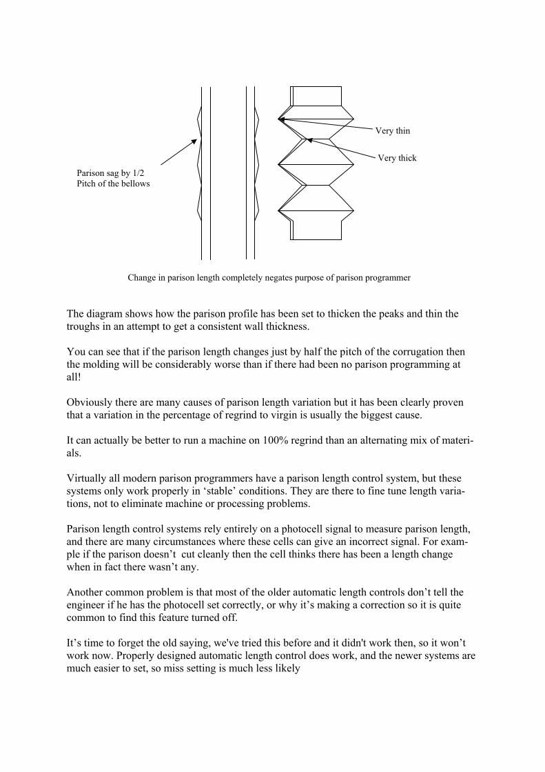
The diagram shows how the parison profile has been set to thicken the peaks and thin the troughs in an attempt to get a consistent wall thickness. You can see that if the parison length changes just by half the pitch of the corrugation then the molding will be considerably worse than if there had been no parison programming at all! Obviously there are many causes of parison length variation but it has been clearly proven that a variation in the percentage of regrind to virgin is usually the biggest cause. It can actually be better to run a machine on 100% regrind than an alternating mix of materi-als. Virtually all modern parison programmers have a parison length control system, but these systems only work properly in ‘stable’ conditions. They are there to fine tune length varia-tions, not to eliminate machine or processing problems. Parison length control systems rely entirely on a photocell signal to measure parison length, and there are many circumstances where these cells can give an incorrect signal. For exam-ple if the parison doesn’t cut cleanly then the cell thinks there has been a length change when in fact there wasn’t any. Another common problem is that most of the older automatic length controls don’t tell the engineer if he has the photocell set correctly, or why it’s making a correction so it is quite common to find this feature turned off. It’s time to forget the old saying, we've tried this before and it didn't work then, so it won’t work now. Properly designed automatic length control does work, and the newer systems are much easier to set, so miss setting is much less likely
Parison sag by 1/2 Pitch of the bellows
Very thin
Very thick
Change in parison length completely negates purpose of parison programmer
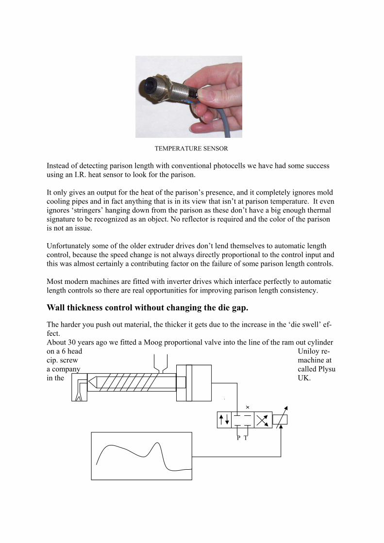
TEMPERATURE SENSOR Instead of detecting parison length with conventional photocells we have had some success using an I.R. heat sensor to look for the parison. It only gives an output for the heat of the parison’s presence, and it completely ignores mold cooling pipes and in fact anything that is in its view that isn’t at parison temperature. It even ignores ‘stringers’ hanging down from the parison as these don’t have a big enough thermal signature to be recognized as an object. No reflector is required and the color of the parison is not an issue. Unfortunately some of the older extruder drives don’t lend themselves to automatic length control, because the speed change is not always directly proportional to the control input and this was almost certainly a contributing factor on the failure of some parison length controls. Most modern machines are fitted with inverter drives which interface perfectly to automatic length controls so there are real opportunities for improving parison length consistency. Wall thickness control without changing the die gap. The harder you push out material, the thicker it gets due to the increase in the ‘die swell’ ef-fect. About 30 years ago we fitted a Moog proportional valve into the line of the ram out cylinder on a 6 head Uniloy re-cip. screw machine at a company called Plysu in the UK.
P T
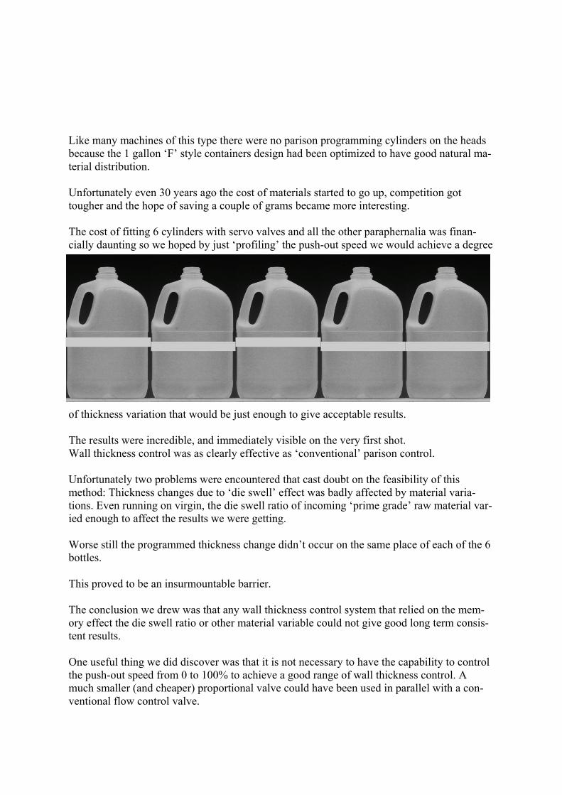
Like many machines of this type there were no parison programming cylinders on the heads because the 1 gallon ‘F’ style containers design had been optimized to have good natural ma-terial distribution. Unfortunately even 30 years ago the cost of materials started to go up, competition got tougher and the hope of saving a couple of grams became more interesting. The cost of fitting 6 cylinders with servo valves and all the other paraphernalia was finan-cially daunting so we hoped by just ‘profiling’ the push-out speed we would achieve a degree
of thickness variation that would be just enough to give acceptable results. The results were incredible, and immediately visible on the very first shot. Wall thickness control was as clearly effective as ‘conventional’ parison control. Unfortunately two problems were encountered that cast doubt on the feasibility of this method: Thickness changes due to ‘die swell’ effect was badly affected by material varia-tions. Even running on virgin, the die swell ratio of incoming ‘prime grade’ raw material var-ied enough to affect the results we were getting. Worse still the programmed thickness change didn’t occur on the same place of each of the 6 bottles. This proved to be an insurmountable barrier. The conclusion we drew was that any wall thickness control system that relied on the mem-ory effect the die swell ratio or other material variable could not give good long term consis-tent results. One useful thing we did discover was that it is not necessary to have the capability to control the push-out speed from 0 to 100% to achieve a good range of wall thickness control. A much smaller (and cheaper) proportional valve could have been used in parallel with a con-ventional flow control valve.
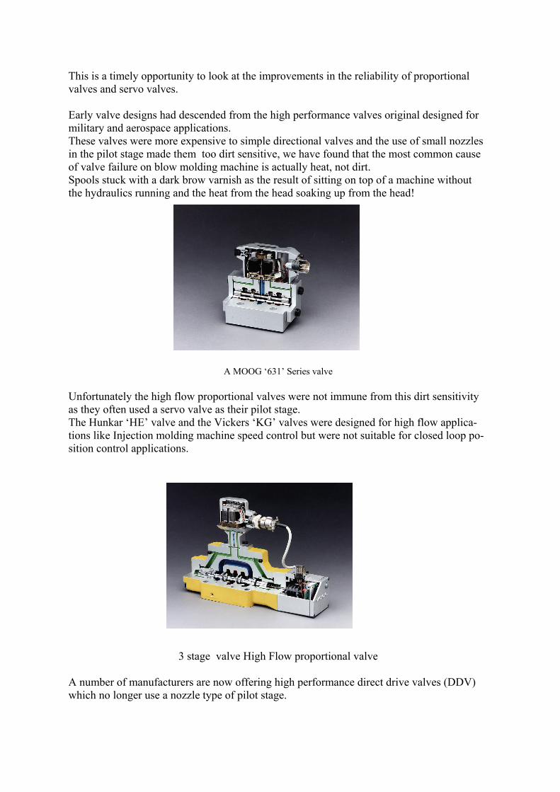
This is a timely opportunity to look at the improvements in the reliability of proportional valves and servo valves. Early valve designs had descended from the high performance valves original designed for military and aerospace applications. These valves were more expensive to simple directional valves and the use of small nozzles in the pilot stage made them too dirt sensitive, we have found that the most common cause of valve failure on blow molding machine is actually heat, not dirt. Spools stuck with a dark brow varnish as the result of sitting on top of a machine without the hydraulics running and the heat from the head soaking up from the head!
A MOOG ‘631’ Series valve
Unfortunately the high flow proportional valves were not immune from this dirt sensitivity as they often used a servo valve as their pilot stage. The Hunkar ‘HE’ valve and the Vickers ‘KG’ valves were designed for high flow applica-tions like Injection molding machine speed control but were not suitable for closed loop po-sition control applications.
3 stage valve High Flow proportional valve A number of manufacturers are now offering high performance direct drive valves (DDV) which no longer use a nozzle type of pilot stage.
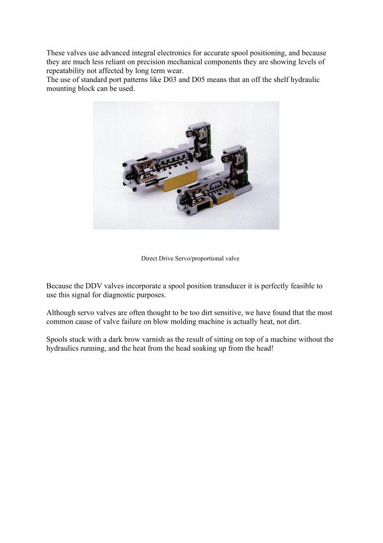
These valves use advanced integral electronics for accurate spool positioning, and because they are much less reliant on precision mechanical components they are showing levels of repeatability not affected by long term wear. The use of standard port patterns like D03 and D05 means that an off the shelf hydraulic mounting block can be used.
Direct Drive Servo/proportional valve
Because the DDV valves incorporate a spool position transducer it is perfectly feasible to use this signal for diagnostic purposes. Although servo valves are often thought to be too dirt sensitive, we have found that the most common cause of valve failure on blow molding machine is actually heat, not dirt. Spools stuck with a dark brow varnish as the result of sitting on top of a machine without the hydraulics running, and the heat from the head soaking up from the head!
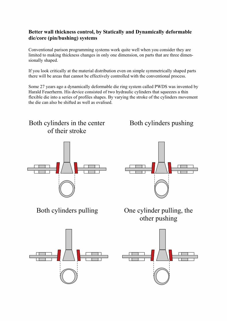
Better wall thickness control, by Statically and Dynamically deformable die/core (pin/bushing) systems Conventional parison programming systems work quite well when you consider they are limited to making thickness changes in only one dimension, on parts that are three dimen-sionally shaped. If you look critically at the material distribution even on simple symmetrically shaped parts there will be areas that cannot be effectively controlled with the conventional process. Some 27 years ago a dynamically deformable die ring system called PWDS was invented by Harald Feuerherm. His device consisted of two hydraulic cylinders that squeezes a thin flexible die into a series of profiles shapes. By varying the stroke of the cylinders movement the die can also be shifted as well as ovalised.
Both cylinders pushing Both cylinders in the center of their stroke
Both cylinders pulling One cylinder pulling, the other pushing
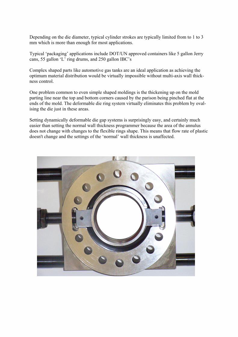
Depending on the die diameter, typical cylinder strokes are typically limited from to 1 to 3 mm which is more than enough for most applications. Typical ‘packaging’ applications include DOT/UN approved containers like 5 gallon Jerry cans, 55 gallon ‘L’ ring drums, and 250 gallon IBC’s Complex shaped parts like automotive gas tanks are an ideal application as achieving the optimum material distribution would be virtually impossible without multi-axis wall thick-ness control. One problem common to even simple shaped moldings is the thickening up on the mold parting line near the top and bottom corners caused by the parison being pinched flat at the ends of the mold. The deformable die ring system virtually eliminates this problem by oval-ising the die just in these areas. Setting dynamically deformable die gap systems is surprisingly easy, and certainly much easier than setting the normal wall thickness programmer because the area of the annulus does not change with changes to the flexible rings shape. This means that flow rate of plastic doesn't change and the settings of the ‘normal’ wall thickness is unaffected.
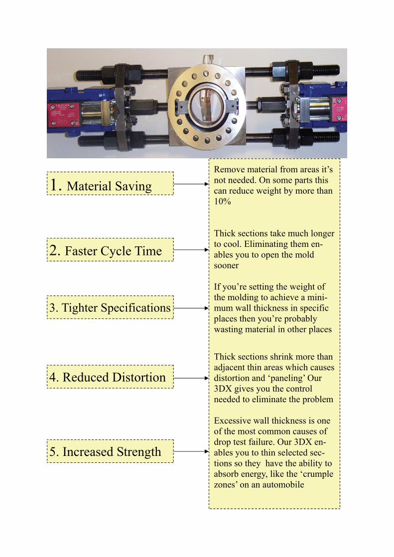
Remove material from areas it’s not needed. On some parts this can reduce weight by more than 10% Thick sections take much longer to cool. Eliminating them en-ables you to open the mold sooner If you’re setting the weight of the molding to achieve a mini-mum wall thickness in specific places then you’re probably wasting material in other places
Thick sections shrink more than adjacent thin areas which causes distortion and ‘paneling’ Our 3DX gives you the control needed to eliminate the problem Excessive wall thickness is one of the most common causes of drop test failure. Our 3DX en-ables you to thin selected sec-tions so they have the ability to absorb energy, like the ‘crumple zones’ on an automobile
1. Material Saving
2. Faster Cycle Time
3. Tighter Specifications
4. Reduced Distortion
5. Increased Strength
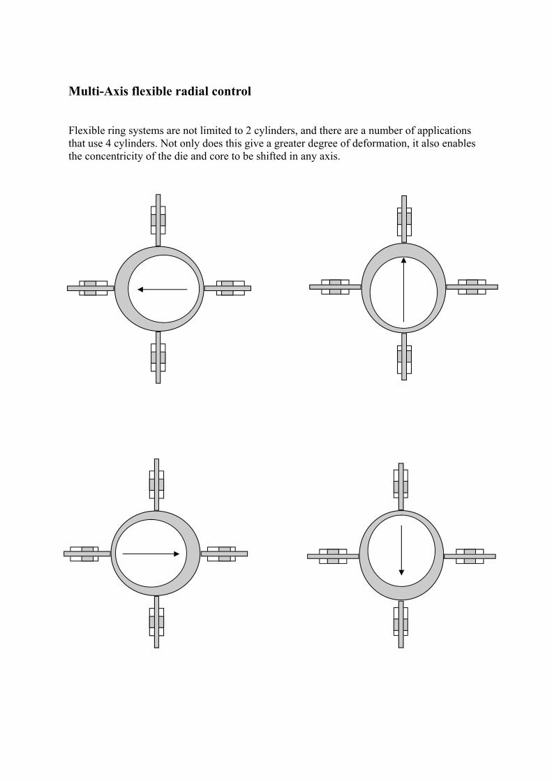
Multi-Axis flexible radial control Flexible ring systems are not limited to 2 cylinders, and there are a number of applications that use 4 cylinders. Not only does this give a greater degree of deformation, it also enables the concentricity of the die and core to be shifted in any axis.
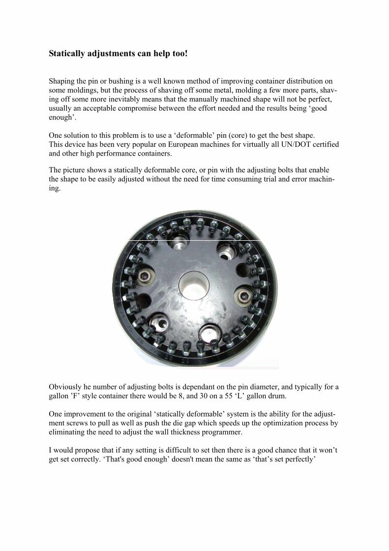
Statically adjustments can help too! Shaping the pin or bushing is a well known method of improving container distribution on some moldings, but the process of shaving off some metal, molding a few more parts, shav-ing off some more inevitably means that the manually machined shape will not be perfect, usually an acceptable compromise between the effort needed and the results being ‘good enough’. One solution to this problem is to use a ‘deformable’ pin (core) to get the best shape. This device has been very popular on European machines for virtually all UN/DOT certified and other high performance containers. The picture shows a statically deformable core, or pin with the adjusting bolts that enable the shape to be easily adjusted without the need for time consuming trial and error machin-ing. Obviously he number of adjusting bolts is dependant on the pin diameter, and typically for a gallon ’F’ style container there would be 8, and 30 on a 55 ‘L’ gallon drum. One improvement to the original ‘statically deformable’ system is the ability for the adjust-ment screws to pull as well as push the die gap which speeds up the optimization process by eliminating the need to adjust the wall thickness programmer. I would propose that if any setting is difficult to set then there is a good chance that it won’t get set correctly. ‘That's good enough’ doesn't mean the same as ‘that’s set perfectly’

Electrical Actuators for Parison control We hear a lot about ‘all electric’ molding machines, so does it make sense to replace any of the hydraulic function with electric drives? Probably not, and certainly not for energy saving reasons. Replacing the hydraulic parison control actuator with an electric one would hardly make any noticeable difference to the ma-chines overall energy consumption although it would cure some of the oil leaks! We have retrofitted a Moog electric parison actuator onto a Rommelag ’Form Fill and Seal’ blow molder as this was a clean room application and we wanted to avoid any possibility of oil leaking into the moulding area.
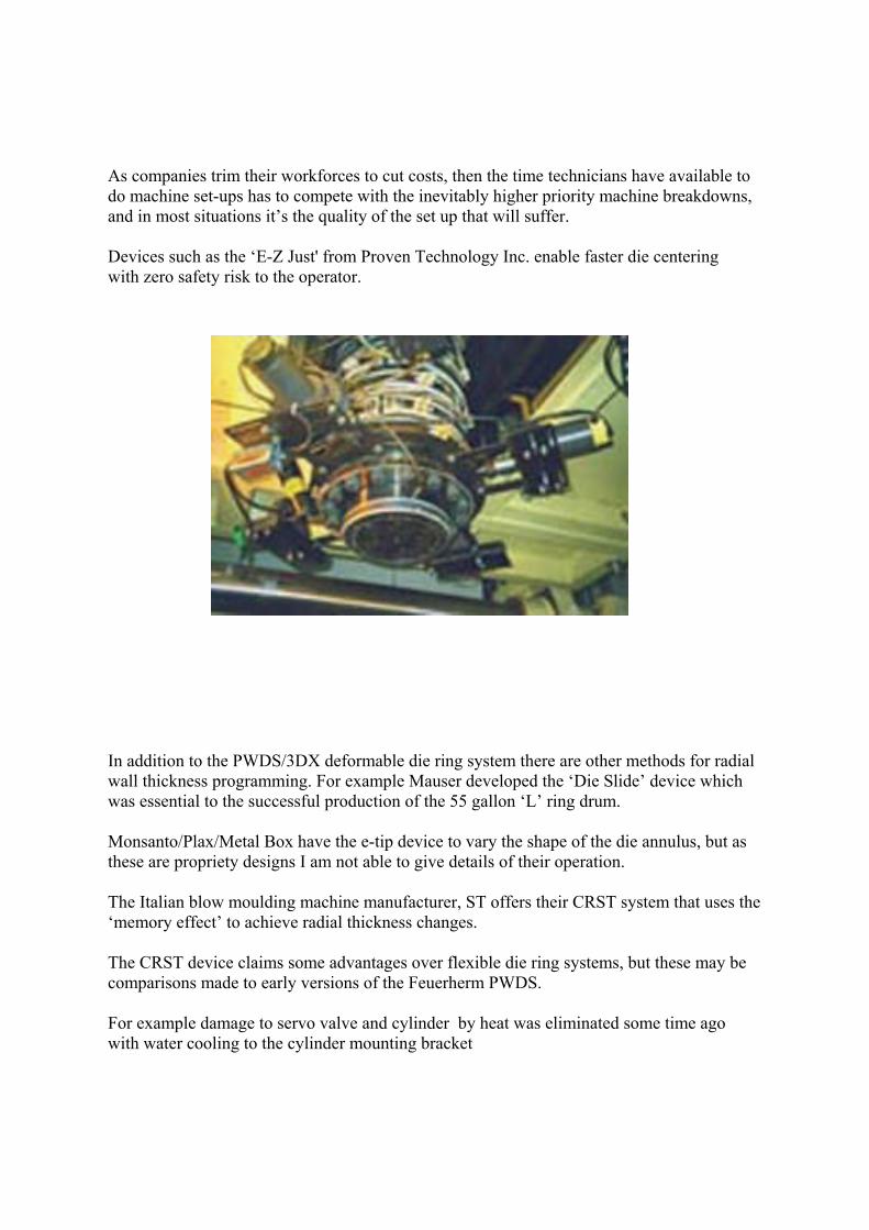
As companies trim their workforces to cut costs, then the time technicians have available to do machine set-ups has to compete with the inevitably higher priority machine breakdowns, and in most situations it’s the quality of the set up that will suffer. Devices such as the ‘E-Z Just' from Proven Technology Inc. enable faster die centering with zero safety risk to the operator. In addition to the PWDS/3DX deformable die ring system there are other methods for radial wall thickness programming. For example Mauser developed the ‘Die Slide’ device which was essential to the successful production of the 55 gallon ‘L’ ring drum. Monsanto/Plax/Metal Box have the e-tip device to vary the shape of the die annulus, but as these are propriety designs I am not able to give details of their operation. The Italian blow moulding machine manufacturer, ST offers their CRST system that uses the ‘memory effect’ to achieve radial thickness changes. The CRST device claims some advantages over flexible die ring systems, but these may be comparisons made to early versions of the Feuerherm PWDS. For example damage to servo valve and cylinder by heat was eliminated some time ago with water cooling to the cylinder mounting bracket
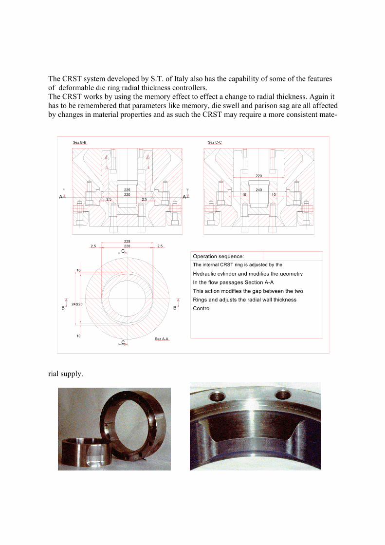
The CRST system developed by S.T. of Italy also has the capability of some of the features of deformable die ring radial thickness controllers. The CRST works by using the memory effect to effect a change to radial thickness. Again it has to be remembered that parameters like memory, die swell and parison sag are all affected by changes in material properties and as such the CRST may require a more consistent mate-
rial supply.
220225
2,5 2,5
220
24010 10
2,5 220 2,5225
Sez B-B Sez C-C
A
B B
A
C
CSez A-A
10
220
10
240
Operation sequence:The internal CRST ring is adjusted by the
Hydraulic cylinder and modifies the geometryIn the flow passages Section A-AThis action modifies the gap between the twoRings and adjusts the radial wall thicknessControl

All the devices we have reviewed have the potential to make improvements to the blow moulding process by optimizing material distribution: 1. Material savings can be made by reducing unnecessary thick sections. 2. Part strength can be increased by thickening thin areas. 3. Cycle time can be improved by redistributing the thick slow cooling areas towards the thinner areas. 4. Surface distortion can be reduced or eliminated by reducing unnecessary thick sections. 5. Critical thickness tolerances can be achieved more easily. 6. Scrap can be reduced by producing moldings well inside specification, not running near the edge of process limits. For over 25 years deformable die ring systems have not always been readily available for all US built blow molding machines due to certain marketing policies of the original patent holder. This is no longer the case and the technology is now as available to American OEM’s and end users as it has been to the European market. Upgrading an existing parison programmer is quick, relatively inexpensive, and can easily give paybacks in less than 6 months. The savings can be due to improved material distribution, and the easier set-ability of mod-ern systems but very often it is the general improvement in reliability and shot to shot repeat-ability that make the most significant improvement. Its always been impossible to estimate the true cost of unreliability. Its not just the downtime or the scrap, how do you put a price on frayed nerves or the damage done to customer relationships ? Much to the frustration of the blow molding machine manufacturers, a properly maintained machine can last 30 years or more. Adding features like flexible die rings, deformable pins and new electronic controls can bring a machines performance capability acceptably near to a new machine. With the general squeeze on profits more and more companies are opting to upgrade existing machines instead of replace them. This is often viable on large accumulator head machines but can be false economy on small bottle machines. To be profitable, bottle machines have to be capable of fast cycling and you really will only get that on a modern machine with an integral take-out deflash system. There has never been a better time to improve the performance of your blow molding ma-chines, and I hope that some of the equipment we’ve discussed today has shown you that there are many things you can investigate.

We would like to thank the following for the information they provided to help preparing this paper: Robert A Slawska David Plews 5 Woodshire Way Moog Controls Ltd Hillsborough Ashchurch NJ 08844 Gloucestershire GL45 5HZ Phone (908) 359-7888 UK Nick Hunkar Carlo Gotti JHWebWorks S.T. P.O. Box 995 Via Della Giardina Hilliard 200052 Monza OH 43026 Italy Phone 39-039 27061 Special thanks to Frank Kennedy Sterling Div. of Davis-Standard Somerville NJ 08876 Phone (908) 722 6000