Embed Size (px)
Citation preview
Contents
1. Zusammenfassung . . . . . . . . . . . . . . . . . . . . . . . . . . . . . . . . . . . . . . . . . . . . . . . . . . . . . . . . . . . . . . . . . . . . . . . . . . . . . . . . . . . . . . . . . 5821. Abstract . . . . . . . . . . . . . . . . . . . . . . . . . . . . . . . . . . . . . . . . . . . . . . . . . . . . . . . . . . . . . . . . . . . . . . . . . . . . . . . . . . . . . . . . . . . . . . . . . . 5821. Introduction . . . . . . . . . . . . . . . . . . . . . . . . . . . . . . . . . . . . . . . . . . . . . . . . . . . . . . . . . . . . . . . . . . . . . . . . . . . . . . . . . . . . . . . . . . . . . . . 5832. Location and Size of the Structure . . . . . . . . . . . . . . . . . . . . . . . . . . . . . . . . . . . . . . . . . . . . . . . . . . . . . . . . . . . . . . . . . . . . . . . . . . . . . 5843. 2.1. Bathymetry . . . . . . . . . . . . . . . . . . . . . . . . . . . . . . . . . . . . . . . . . . . . . . . . . . . . . . . . . . . . . . . . . . . . . . . . . . . . . . . . . . . . . . . . . . . . 5843. 2.2. Topography . . . . . . . . . . . . . . . . . . . . . . . . . . . . . . . . . . . . . . . . . . . . . . . . . . . . . . . . . . . . . . . . . . . . . . . . . . . . . . . . . . . . . . . . . . . 5843. Geology . . . . . . . . . . . . . . . . . . . . . . . . . . . . . . . . . . . . . . . . . . . . . . . . . . . . . . . . . . . . . . . . . . . . . . . . . . . . . . . . . . . . . . . . . . . . . . . . . . 5844. The New Airborne Geophysical Survey, and Equipment Used . . . . . . . . . . . . . . . . . . . . . . . . . . . . . . . . . . . . . . . . . . . . . . . . . . . . . . . . 5873. 4.1. Aircraft and Field Survey . . . . . . . . . . . . . . . . . . . . . . . . . . . . . . . . . . . . . . . . . . . . . . . . . . . . . . . . . . . . . . . . . . . . . . . . . . . . . . . . . 5873. 4.2. Magnetics . . . . . . . . . . . . . . . . . . . . . . . . . . . . . . . . . . . . . . . . . . . . . . . . . . . . . . . . . . . . . . . . . . . . . . . . . . . . . . . . . . . . . . . . . . . . . 5883. 4.3. Aero-Electromagnetic Data (AEM) . . . . . . . . . . . . . . . . . . . . . . . . . . . . . . . . . . . . . . . . . . . . . . . . . . . . . . . . . . . . . . . . . . . . . . . . . 5893. 4.4. Gamma Ray Radiation . . . . . . . . . . . . . . . . . . . . . . . . . . . . . . . . . . . . . . . . . . . . . . . . . . . . . . . . . . . . . . . . . . . . . . . . . . . . . . . . . . . 5903. 4.5. Navigation and Other Instruments . . . . . . . . . . . . . . . . . . . . . . . . . . . . . . . . . . . . . . . . . . . . . . . . . . . . . . . . . . . . . . . . . . . . . . . . . . 5913. 4.6. Data Recording and Processing . . . . . . . . . . . . . . . . . . . . . . . . . . . . . . . . . . . . . . . . . . . . . . . . . . . . . . . . . . . . . . . . . . . . . . . . . . . . 5915. Geophysical Maps . . . . . . . . . . . . . . . . . . . . . . . . . . . . . . . . . . . . . . . . . . . . . . . . . . . . . . . . . . . . . . . . . . . . . . . . . . . . . . . . . . . . . . . . . 5923. 5.1. Magnetic Maps . . . . . . . . . . . . . . . . . . . . . . . . . . . . . . . . . . . . . . . . . . . . . . . . . . . . . . . . . . . . . . . . . . . . . . . . . . . . . . . . . . . . . . . . . 5933. 5.1. 5.1.1. Magnetic Structure: Example of Interpretations . . . . . . . . . . . . . . . . . . . . . . . . . . . . . . . . . . . . . . . . . . . . . . . . . . . . . . . . . . . 5933. 5.2. Electromagnetic Maps . . . . . . . . . . . . . . . . . . . . . . . . . . . . . . . . . . . . . . . . . . . . . . . . . . . . . . . . . . . . . . . . . . . . . . . . . . . . . . . . . . . 5953. 5.3. Radiometric Maps . . . . . . . . . . . . . . . . . . . . . . . . . . . . . . . . . . . . . . . . . . . . . . . . . . . . . . . . . . . . . . . . . . . . . . . . . . . . . . . . . . . . . . . 5976. Discussion and Conclusions . . . . . . . . . . . . . . . . . . . . . . . . . . . . . . . . . . . . . . . . . . . . . . . . . . . . . . . . . . . . . . . . . . . . . . . . . . . . . . . . . . 5988. Acknowledgements . . . . . . . . . . . . . . . . . . . . . . . . . . . . . . . . . . . . . . . . . . . . . . . . . . . . . . . . . . . . . . . . . . . . . . . . . . . . . . . . . . . . . . . . . 5998. References . . . . . . . . . . . . . . . . . . . . . . . . . . . . . . . . . . . . . . . . . . . . . . . . . . . . . . . . . . . . . . . . . . . . . . . . . . . . . . . . . . . . . . . . . . . . . . . 600
581
J A H R B U C H D E R G E O L O G I S C H E N B U N D E S A N S TA LTJb. Geol. B.-A. ISSN 0016–7800 Band 143 Heft 4 S. 581–604 Wien, Dezember 2003
***) LAURI J. PESONEN, Division of Geophysics, University of Helsinki, P.O. Box 64, FIN 00014 Helsinki, Finland.e-mail: [email protected].
***) CHRISTIAN KOEBERL (corresponding author), Department of Geological Sciences, University of Vienna, Althanstraße 14, A-1090 Vienna, Austria.e-mail: [email protected].
***) HEIKKI HAUTANIEMI, Department of Geophysics, Geological Survey of Finland, P.O. Box 96, FIN-02151 Espoo, Finland.e-mail: [email protected].
Airborne Geophysical Surveyof the Lake Bosumtwi Meteorite Impact Structure
(Southern Ghana) –Geophysical Mapswith Descriptions
LAURI J. PESONEN*), CHRISTIAN KOEBERL**) & HEIKKI HAUTANIEMI***)
24 Text-Figures
GhanaLake Bosumtwi
MeteoritImpaktkrater
Österreichische Karte 1 : 50.000 AerogeophysikBlatt 134 Magnetik
ElektromagnetikGammastrahlenmessung
Aerogeophysikalische Untersuchungen der Lake-Bosumtwi-Impaktstruktur im südlichen Ghana –Geophysikalische Karten und Beschreibungen
Zusammenfassung
Im Jahre 1997 wurde vom Finnischen Geologischen Dienst in Zusammenarbeit mit der Universität Wien und dem Geological Survey Department ofGhana eine hochauflösende aerogeophysikalische Untersuchung der Lake Bosumtwi-Impaktstruktur (Ghana) durchgeführt. Die technischen Parame-ter der Datengewinnung und die Resultate der Untersuchung werden in einer Serie von geophysikalischen (Magnetik, Elektromagnetik und Gamma-Strahlung) Karten im Maßstab 1 : 50000 präsentiert. Kurzbeschreibungen jeder Karte sollen behilflich sein bei künftigen geophysikalischen Modellie-rungen der Struktur und bei der Auswahl von Bohrpunkten im Kraterboden; Bohrungen sind für Mitte 2004 im Rahmen eines internationalen und inter-disziplinären Projektes vorgesehen.
582
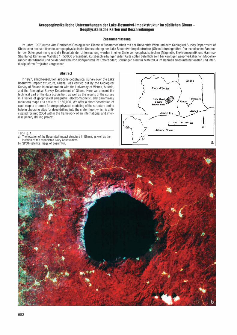
Text-Fig. 1.a) The location of the Bosumtwi impact structure in Ghana, as well as the
location of the associated Ivory Cost tektites.b) SPOT-satellite image of Bosumtwi. a
b
Abstract
In 1997, a high-resolution airborne geophysical survey over the LakeBosumtwi impact structure, Ghana, was carried out by the GeologicalSurvey of Finland in collaboration with the University of Vienna, Austria,and the Geological Survey Department of Ghana. Here we present thetechnical part of the data acquisition, as well as the results of the surveyin a series of geophysical (magnetic, electromagnetic, and gamma-rayradiation) maps at a scale of 1 : 50,000. We offer a short description ofeach map to promote future geophysical modeling of the structure and tohelp in choosing sites for deep drilling into the crater floor, which is anti-cipated for mid 2004 within the framework of an international and inter-disciplinary drilling project.
583
The Bosumtwi impact crater is located in the AshantiProvince of Ghana, near the town of Kumasi, centered at06°32’N and 01°25’W (Text-Fig. 1). It is one of only about18 impact structures in Africa (e.g., KOEBERL, 1994), and itis probably the youngest large impact crater known onEarth.
The structure, which has an age of 1.07 Million years, isalmost completely filled by Lake Bosumtwi, and has a rim-to-rim diameter of about 10.5 km.
The first suggestions that the Bosumtwi crater is thesource crater for the Ivory Coast tektites were made in theearly 1960s. Ivory Coast tektites were first reported in 1934from a geographically rather restricted area in the IvoryCoast (Côte d’Ivoire), West Africa. Microtektites have beenreported from deep-sea sediments of corresponding agefrom the eastern equatorial Atlantic Ocean west of Africa.Ivory Coast tektites and the Bosumtwi crater have thesame age (1.07 Ma [KOEBERL et al., 1997a]), and there areclose similarities between the isotopic and chemical com-positions of the tektites and crater rocks (for references
and details, see KOEBERL et al. [1998]). These observa-tions strongly support a connection between the crater andthe tektites.
In spite of this, the subsurface structure of Bosumtwi ispoorly known due to lack of drillings in the center of thestructure (now occupied by Lake Bosumtwi) and lack ofhigh-resolution geophysical data. The Geological Survey ofFinland (GSF) and the Geological Survey Department ofGhana (GSDG) agreed in 1996 to carry out an airbornegeophysical survey in Ghana, Africa, with a Finnish-ownedTwin Otter aircraft.
The survey, conducted by Malmilento Co., was carriedout in March of 1997 in collaboration with the MineralsCommission of Ghana and the Swedish Geological Survey.A smaller side-project was negotiated between the GSFand GSDG to carry out a low altitude airborne geophysicalsurvey of the Lake Bosumtwi meteorite impact structure insouthern Ghana, during the time when the aircraft wastransported from Accra to the main survey area in north-western Ghana.
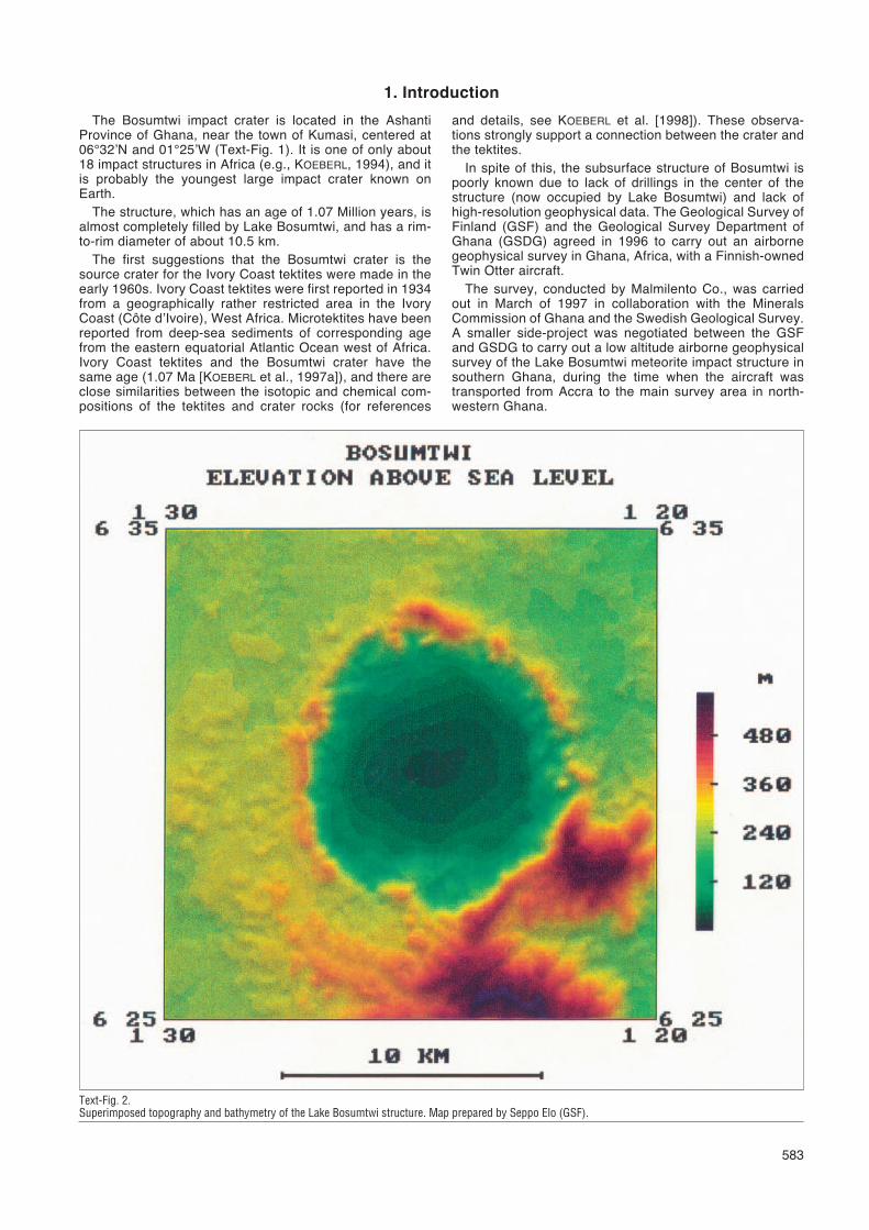
Text-Fig. 2.Superimposed topography and bathymetry of the Lake Bosumtwi structure. Map prepared by Seppo Elo (GSF).
1. Introduction
584
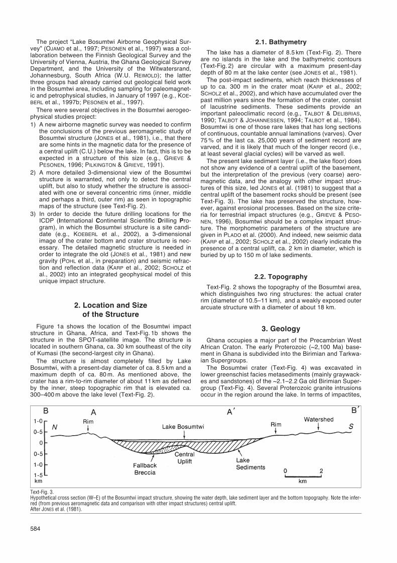
Text-Fig. 3.Hypothetical cross section (W–E) of the Bosumtwi impact structure, showing the water depth, lake sediment layer and the bottom topography. Note the infer-red (from previous aeromagnetic data and comparison with other impact structures) central uplift.After JONES et al. (1981).
The project “Lake Bosumtwi Airborne Geophysical Sur-vey” (OJAMO et al., 1997; PESONEN et al., 1997) was a col-laboration between the Finnish Geological Survey and theUniversity of Vienna, Austria, the Ghana Geological SurveyDepartment, and the University of the Witwatersrand,Johannesburg, South Africa (W.U. REIMOLD); the latterthree groups had already carried out geological field workin the Bosumtwi area, including sampling for paleomagnet-ic and petrophysical studies, in January of 1997 (e.g., KOE-BERL et al., 1997b; PESONEN et al., 1997).
There were several objectives in the Bosumtwi aerogeo-physical studies project:1) A new airborne magnetic survey was needed to confirm
the conclusions of the previous aeromagnetic study ofBosumtwi structure (JONES et al., 1981), i.e., that thereare some hints in the magnetic data for the presence ofa central uplift (C.U.) below the lake. In fact, this is to beexpected in a structure of this size (e.g., GRIEVE &PESONEN, 1996; PILKINGTON & GRIEVE, 1991).
2) A more detailed 3-dimensional view of the Bosumtwistructure is warranted, not only to detect the centraluplift, but also to study whether the structure is associ-ated with one or several concentric rims (inner, middleand perhaps a third, outer rim) as seen in topographicmaps of the structure (see Text-Fig. 2).
3) In order to decide the future drilling locations for theICDP (International Continental Scientific Drilling Pro-gram), in which the Bosumtwi structure is a site candi-date (e.g., KOEBERL et al., 2002), a 3-dimensionalimage of the crater bottom and crater structure is nec-essary. The detailed magnetic structure is needed inorder to integrate the old (JONES et al., 1981) and newgravity (POHL et al., in preparation) and seismic refrac-tion and reflection data (KARP et al., 2002; SCHOLZ etal., 2002) into an integrated geophysical model of thisunique impact structure.
2. Location and Sizeof the Structure
Figure 1a shows the location of the Bosumtwi impactstructure in Ghana, Africa, and Text-Fig. 1b shows thestructure in the SPOT-satellite image. The structure islocated in southern Ghana, ca. 30 km southeast of the cityof Kumasi (the second-largest city in Ghana).
The structure is almost completely filled by LakeBosumtwi, with a present-day diameter of ca. 8.5 km and amaximum depth of ca. 80 m. As mentioned above, thecrater has a rim-to-rim diameter of about 11 km as definedby the inner, steep topographic rim that is elevated ca.300–400 m above the lake level (Text-Fig. 2).
2.1. Bathymetry
The lake has a diameter of 8.5 km (Text-Fig. 2). Thereare no islands in the lake and the bathymetric contours(Text-Fig. 2) are circular with a maximum present-daydepth of 80 m at the lake center (see JONES et al., 1981).
The post-impact sediments, which reach thicknesses ofup to ca. 300 m in the crater moat (KARP et al., 2002;SCHOLZ et al., 2002), and which have accumulated over thepast million years since the formation of the crater, consistof lacustrine sediments. These sediments provide animportant paleoclimatic record (e.g., TALBOT & DELIBRIAS,1990; TALBOT & JOHANNESSEN, 1994; TALBOT et al., 1984).Bosumtwi is one of those rare lakes that has long sectionsof continuous, countable annual laminations (varves). Over75 % of the last ca. 25,000 years of sediment record arevarved, and it is likely that much of the longer record (i.e.,at least several glacial cycles) will be varved as well.
The present lake sediment layer (i.e., the lake floor) doesnot show any evidence of a central uplift of the basement,but the interpretation of the previous (very coarse) aero-magnetic data, and the analogy with other impact struc-tures of this size, led JONES et al. (1981) to suggest that acentral uplift of the basement rocks should be present (seeText-Fig. 3). The lake has preserved the structure, how-ever, against erosional processes. Based on the size crite-ria for terrestrial impact structures (e.g., GRIEVE & PESO-NEN, 1996), Bosumtwi should be a complex impact struc-ture. The morphometric parameters of the structure aregiven in PLADO et al. (2000). And indeed, new seismic data(KARP et al., 2002; SCHOLZ et al., 2002) clearly indicate thepresence of a central uplift, ca. 2 km in diameter, which isburied by up to 150 m of lake sediments.
2.2. Topography
Text-Fig. 2 shows the topography of the Bosumtwi area,which distinguishes two ring structures: the actual craterrim (diameter of 10.5–11 km), and a weakly exposed outerarcuate structure with a diameter of about 18 km.
3. Geology
Ghana occupies a major part of the Precambrian WestAfrican Craton. The early Proterozoic (~2,100 Ma) base-ment in Ghana is subdivided into the Birimian and Tarkwa-ian Supergroups.
The Bosumtwi crater (Text-Fig. 4) was excavated inlower greenschist facies metasediments (mainly graywack-es and sandstones) of the ~2.1–2.2 Ga old Birimian Super-group (Text-Fig. 4). Several Proterozoic granite intrusionsoccur in the region around the lake. In terms of impactites,
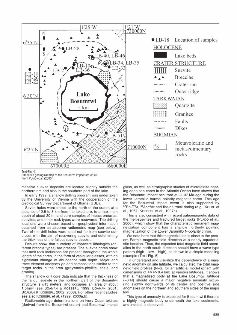
massive suevite deposits are located slightly outside thenorthern rim and also in the southern part of the lake.
In early 1999, a shallow drilling program was undertakenby the University of Vienna with the cooperation of theGeological Survey Department of Ghana (GSD).
Seven holes were drilled to the north of the crater, at adistance of 2.5 to 8 km from the lakeshore, to a maximumdepth of about 30 m, and core samples of impact breccias,suevites, and other rock types were recovered. The drillinglocations were chosen based on geophysical informationobtained from an airborne radiometric map (see below).Two of the drill holes were sited not far from suevite out-crops, with the aim of recovering suevite and determiningthe thickness of the fallout suevite deposit.
Results show that a variety of impactite lithologies (dif-ferent breccia types) are present. The suevite cores showthat melt rock inclusions are present throughout the wholelength of the cores, in the form of vesicular glasses, with nosignificant change of abundance with depth. Major andtrace element analyses yielded compositions similar to thetarget rocks in the area (graywacke-phyllite, shale, andgranite).
The shallow drill core data indicate that the thickness ofthe fallout suevite in the northern part of the Bosumtwistructure is ≤15 meters, and occupies an area of about1.5 km2 (see BOAMAH & KOEBERL, 1999; BOAMAH, 2001;BOAMAH & KOEBERL, 2002, 2003). For other recent studiessee also KOEBERL et al. (1999, 2000a,b).
Radiometric age determinations on Ivory Coast tektites(derived from the Bosumtwi crater) and Bosumtwi impact
glass, as well as stratigraphic studies of microtektite-bear-ing deep sea cores in the Atlantic Ocean have shown thatthe Bosumtwi impact occurred at ~1.07 Ma ago during thelower Jaramillo normal polarity magnetic chron. This agefor the Bosumtwi impact event is also supported by87Rb-87Sr, 39Ar-40Ar and fission track dating (e.g., KOLBE etal., 1967; KOEBERL et al., 1997a).
This is also consistent with recent paleomagnetic data ofthe melt-suevites and fractured target rocks (PLADO et al.,2000), which show that the characteristic remanent mag-netization component has a shallow northerly pointingmagnetization of the Lower Jaramillo N-polarity chron.
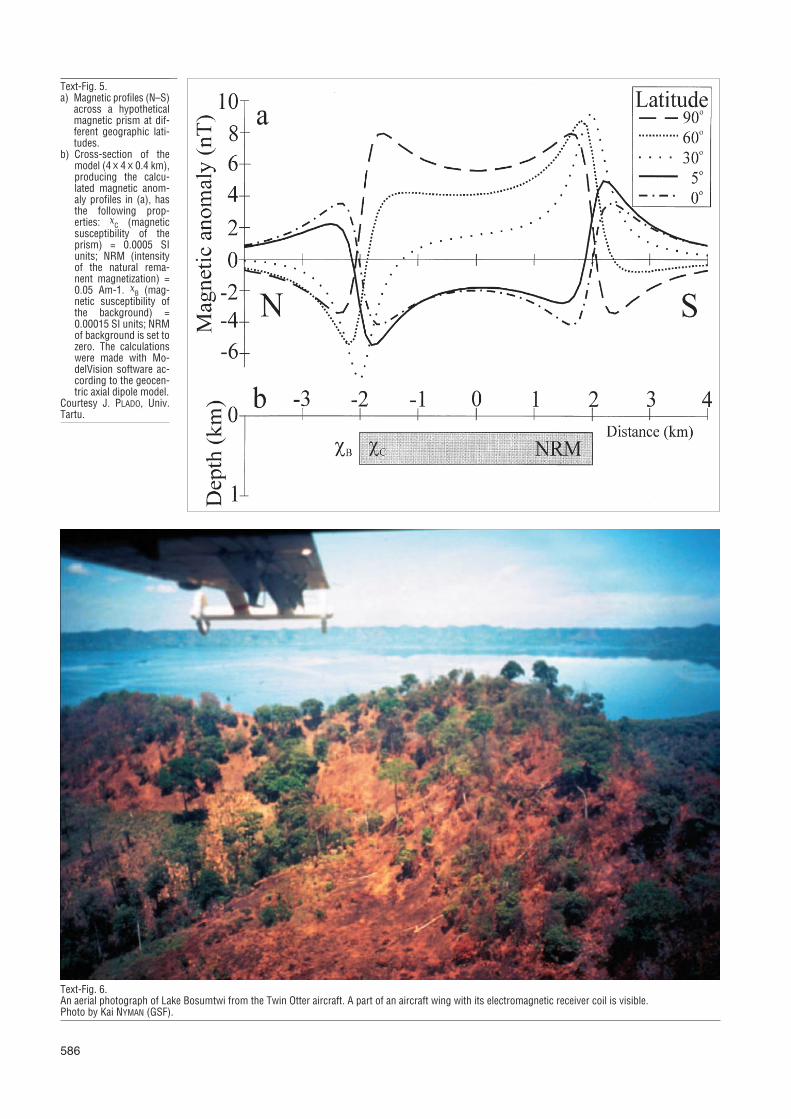
We note here that this magnetization is close to the pres-ent Earth’s magnetic field direction at a nearly equatorialsite location. Thus, the expected total magnetic field anom-alies in the north-south direction should have a wave-typepattern (high – low – high), as shown in a simple modelingexample (Text-Fig. 5).
To understand and visualize the dependence of a mag-netic anomaly on site latitude, we calculated the total mag-netic field profiles (N–S) for an artificial model (prism withdimensions of 4�4�0.4 km) at various latitudes. It showsthat a magnetized body at the Lake Bosumtwi latitude(~6°N) should cause a major negative anomaly occur-ring slightly northwards of its center and positive sideanomalies on the northern and southern sides of the majorlow.
This type of anomaly is expected for Bosumtwi if there isa highly magnetic body underneath the lake sediments,and indeed, is observed.
585
Text-Fig. 4.Simplified geological map of the Bosumtwi impact structure.From PLADO et al. (2000.)
586
Text-Fig. 5.a) Magnetic profiles (N–S)
across a hypotheticalmagnetic prism at dif-ferent geographic lati-tudes.
b) Cross-section of themodel (4 � 4 � 0.4 km),producing the calcu-lated magnetic anom-aly profiles in (a), hasthe following prop-erties: �
C (magneticsusceptibility of theprism) = 0.0005 SIunits; NRM (intensityof the natural rema-nent magnetization) =0.05 Am-1. �
B (mag-netic susceptibility ofthe background) =0.00015 SI units; NRMof background is set tozero. The calculationswere made with Mo-delVision software ac-cording to the geocen-tric axial dipole model.
Courtesy J. PLADO, Univ.Tartu.
Text-Fig. 6.An aerial photograph of Lake Bosumtwi from the Twin Otter aircraft. A part of an aircraft wing with its electromagnetic receiver coil is visible.Photo by Kai NYMAN (GSF).
4. The New Airborne Geophysical Survey,and Equipment Used
4.1. Aircraft and Field SurveyIn order to obtain a more detailed view of the subsurface
structure below and beyond the lake, a high-resolutionaerogeophysical survey across the structure was conduct-ed by the GSF in March 1997.
The survey was done with a DeHaviland two engine TwinOtter DHC-6/300 aircraft owned by Finnair Co. and operat-ed by Malmilento Co (Finland). This aircraft offers severaladvantages in terms of utility and cost, including excellent
performance reserves, low speed handling characteristicsand operational flexibility. The flight speed during themeasurements is 160–220 km/h (44–61 m/s) with a rate ofclimb of 7.5 m/s.
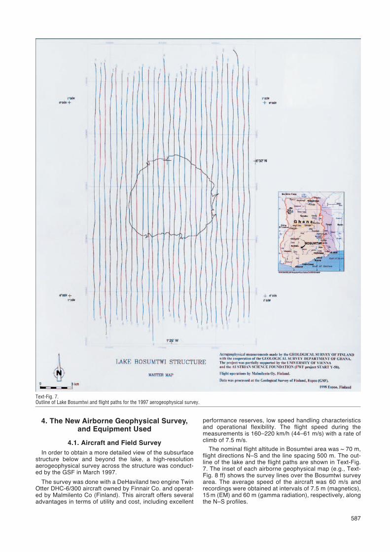
The nominal flight altitude in Bosumtwi area was ~ 70 m,flight directions N–S and the line spacing 500 m. The out-line of the lake and the flight paths are shown in Text-Fig.7. The inset of each airborne geophysical map (e.g., Text-Fig. 8 ff) shows the survey lines over the Bosumtwi surveyarea. The average speed of the aircraft was 60 m/s andrecordings were obtained at intervals of 7.5 m (magnetics),15 m (EM) and 60 m (gamma radiation), respectively, alongthe N–S profiles.
587
Text-Fig. 7.Outline of Lake Bosumtwi and flight paths for the 1997 aerogeophysical survey.
Altogether 30 profiles with an average length of22 km were recorded (Text-Fig. 7). Positioning was doneusing a differential global positioning system (DGPS) andflight elevations were measured with a radar altimeter. Thesurvey consisted of airborne magnetic, electromagnetic,and gamma-ray radiation measurements. All recordingswere done digitally and corrections due to aircraft havebeen performed.
4.2. Magnetics
The total magnetic field intensity (nT) was recorded withtwo single Scintrex MAC-3 cesium magnetometers with aCS-2 sensor and MEP-2111 processor modules.
The magnetometers were installed in the wing tips withan automatic compensation unit (to reduce aircraft mag-netic disturbances); however, only the right wing magne-
588
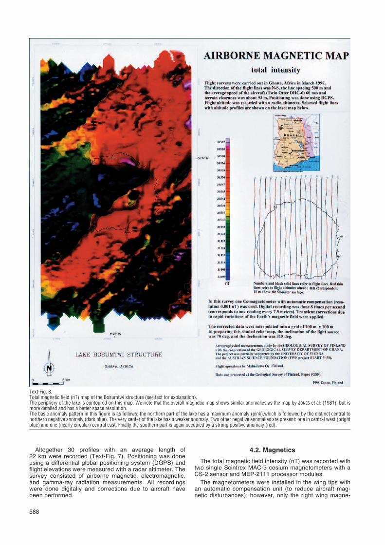
Text-Fig. 8.Total magnetic field (nT) map of the Bosumtwi structure (see text for explanation).The periphery of the lake is contoured on this map. We note that the overall magnetic map shows similar anomalies as the map by JONES et al. (1981), but ismore detailed and has a better space resolution.The basic anomaly pattern in this figure is as follows: the northern part of the lake has a maximum anomaly (pink),which is followed by the distinct central tonorthern negative anomaly (dark blue). The very center of the lake has a weaker anomaly. Two other negative anomalies are present: one in central west (brightblue) and one (nearly circular) central east. Finally the southern part is again occupied by a strong positive anomaly (red).
tometer was in operation for the Bosumtwi survey. Thissystem has a resolution of 0.001 nT and a sensitivity of0.005 nT. The average noise level is 0.0006 nT/sqrt (fre-quency). The registration took place 8 times/second (corre-sponding to an average reading at every 7.5 m).
To reduce the local magnetic variations, a magnetic ref-erence station was installed close to lake Bosumtwi, atKumasi airport, where the total field variations were record-ed throughout the survey days using a Scintrex MAC-3cesium magnetometer. No nearby observatory data wereavailable, so the results are on the level of the measuringdate and place.
4.3. Aero-Electromagnetic Data(AEM)
The aero-electromagnetic (AEM) data were recordedusing a dual frequency, broadside, vertical, coplanar coilconfiguration (Model GSF-95), where the coils are installedat the wing tips and have a separation of 21.36 m.
The used frequencies are 3,125 Hz and 14,368 Hz,respectively. The in-phase (Real, Re-) and quadrature(Imaginary, Im-) components of the EM signal were meas-ured. The recording sensitivity is 1 ppm and the noise lev-els are <6 ppm for both quadrature and in phase compo-nents when the frequency is 3,125 Hz. The corresponding
589
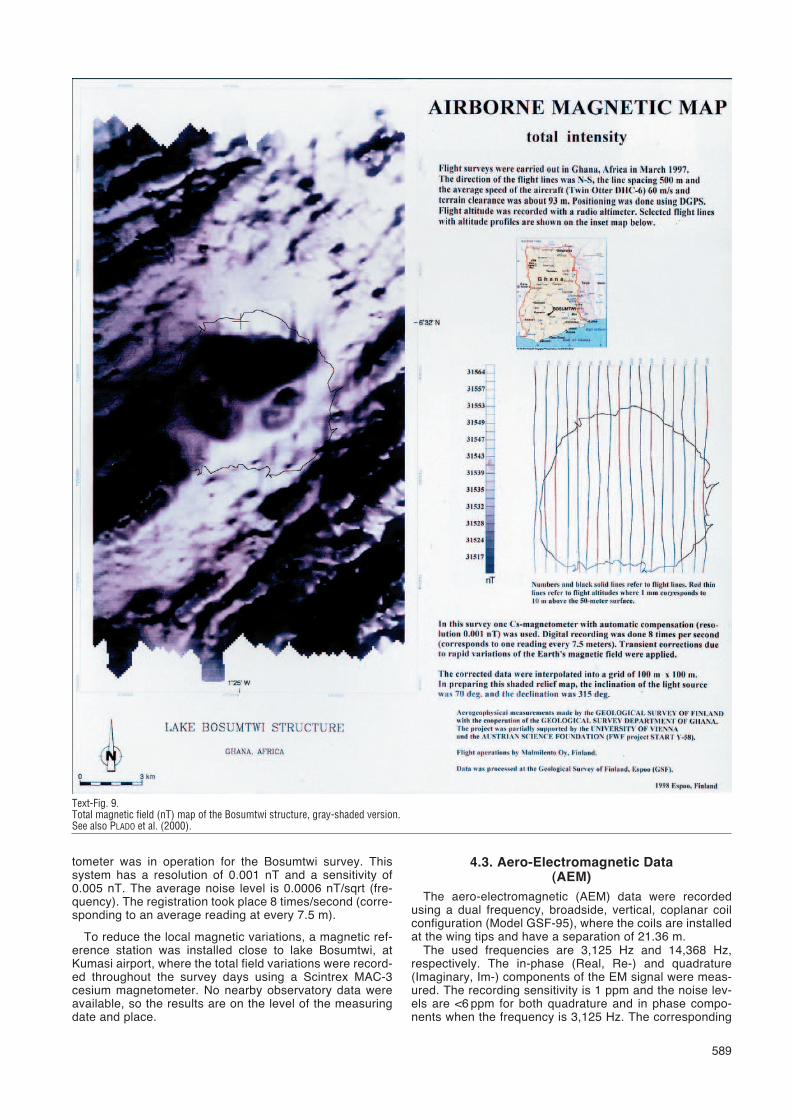
Text-Fig. 9.Total magnetic field (nT) map of the Bosumtwi structure, gray-shaded version.See also PLADO et al. (2000).
590
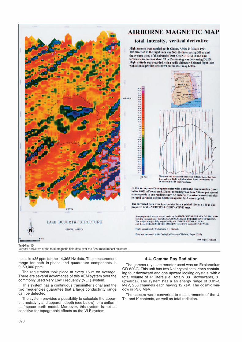
Text-Fig. 10.Vertical derivative of the total magnetic field data over the Bosumtwi impact structure.
noise is <35 ppm for the 14,368 Hz data. The measurementrange for both in-phase and quadrature components is0–50,000 ppm.
The registration took place at every 15 m on average.There are several advantages of this AEM system over thecommonly used Very Low Frequency (VLF) system.
This system has a continuous transmitter signal and thetwo frequencies guarantee that a large conductivity rangecan be detected.
The system provides a possibility to calculate the appar-ent resistivity and apparent depth (see below) for a uniformhalf-space earth model. Moreover, this system is not assensitive for topographic effects as the VLF system.
4.4. Gamma Ray RadiationThe gamma ray spectrometer used was an Exploranium
GR-820/3. This unit has two NaI crystal sets, each contain-ing four downward and one upward looking crystals, with atotal volume of 41 liters (i.e., totally 33 l downwards, 8 lupwards). The system has a an energy range of 0.01–3MeV, 256 channels each having 12 keV. The cosmic win-dow is >3.0 MeV.
The spectra were converted to measurements of the U,Th, and K contents, as well as total radiation.
591
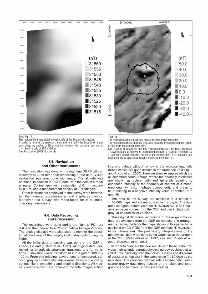
Text-Fig. 11.The regional field map (total intensity, nT) of the Bosumtwi structure.In order to remove the regional trends and to amplify the Bosumtwi relatedanomalies, we applied a 2D-smoothing window with an areal operator of4 x 4 km in a grid of 100 x 100 m.See PLADO et al. (2000) for details.
Text-Fig. 12.The residual magnetic field (nT) map of the Bosumtwi structure.The residual magnetic anomaly (Fig. 5) is obtained by subtracting the region-al field from the original total field.See PLADO et al. (2000) on how this map was prepared from Text-Figs. 9 and11. Symbols are as follows: n = northern maximum; c = central minimum, cu= anomaly pattern possibly related to the central uplift; h = magnetic haloencircling the structure and roughly matching the inner rim.
4.5. Navigationand Other Instruments
The navigation was done with a real time DGPS with anaccuracy of ±2 m after post-processing of the data. Visualnavigation was also done with maps. The altitude wasobtained, in addition to DGPS data, with the help of a radaraltimeter (Collins-type), with a resolution of 0.1 m, accura-cy 0.5 m, and a measurement density of 2 readings/s.
Other instruments employed in the survey were barome-ter, thermometer, accelerometer, and a spheres monitor.Moreover, the survey was video-taped for later cross-checking if necessary.
4.6. Data Recordingand Processing
The recordings were done during the flight to PC harddisk and then copied to a PC-compatible Iomega Zip disk.The analog displays were also used to monitor the opera-tional conditions of the geophysical instruments during theflights.
All the initial data processing was done at the GSF inEspoo, Finland (OJAMO et al., 1997). All original data (cor-rected for aircraft disturbances, transients and for varia-tions in elevation) were transformed into a grid of 100 m x100 m. From this gridding, several sets of contoured, col-ored, gray, or shaded relief maps were drawn with applyingvarious filters, smoothing and shading directions. All mag-netic maps shown here represent the total magnetic field
intensity values without removing the regional magnetictrends (which are quite distinct in the area; see Text-Fig. 8and PLADO et al., 2000). Here we show examples which areall smoothed contour maps, where the anomaly intensitiesare shown as colors, with red generally pointing toenhanced intensity of the anomaly or content of a meas-ured quantity (e.g., in-phase component), and green toblue pointing to a negative intensity value or content of aquantity.
The data of the survey are available in a series of1 : 50,000 maps and are reproduced in this paper. The dataare also, upon request (contact H. HAUTANIEMI, GSF) avail-able as paper copies from the GSF and can include color,gray, or shaded-relief versions.
The original flight-line recordings of these geophysicaldata are available from the GSF on request, and arrange-ments can be made for the maps shown in this paper to beavailable on CD-ROM from the GSF (contact H. HAUTANIE-MI for information). The preliminary interpretations of thegeophysical data were done at the Geophysics Departmentof the GSF (PESONEN et al., 1997; see also PLADO et al.,2000, PESONEN et al., 2001).
In order to compare the new results with those of the pre-vious high-altitude aerogeophysical survey by JONES et al.(1981), we have digitized the previous maps and diagramsof JONES et al. (op cit.) in the same scale (1 : 50,000) as thenew data. The previous data include aeromagnetic, somescarce gravity data (only outside of the lake), and topo-graphic and bathymetric data (see below).
5. Geophysical MapsWe have prepared a set of 16 new geophysical maps in
1 : 50,000 of the Bosumtwi survey. They are:� Three magnetic maps (colored and gray tone total field)� – Total intensity, colored
– Total intensity, shaded relief– 2nd vertical derivative, colored
� Eight electromagnetic maps– in-phase and quadrature component maps– f = 3,125 Hz– in-phase and quadrature component maps– f = 14,386 Hz
– apparent resistivity maps for both frequencies– apparent depth maps for both frequencies
� Four gamma radiation maps: the U, Th, K and total radi-ation content maps.
We note here that other maps were also prepared (andcan be ordered from GSF), but these turned out to be verycomplex and were, thus, not used in the follow-up studies.These include magnetic maps in which the data werereduced to the pole using the Euler transformation tech-niques.
592
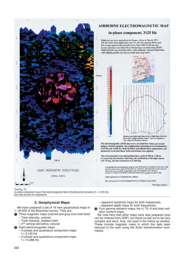
Text-Fig. 13.In-phase component map of the electromagnetic field of the Bosumtwi structure (f = 3,125 Hz).See map and text for explanation.
593
5.1. Magnetic Maps
Several types of magnetic maps have been prepared(Text-Figs. 8 and 9). All magnetic maps are total magneticfield values (nT) as reduced to the level of the field inGhana (which is typically 31,000±1,000 nT). They are thusnot IGRF-values.
Text-Fig. 8 serves as an example of the map displayfrom this survey. On the upper right corner the location ofthe Bosumtwi in Ghana is shown. The inset in middle rightshows the flight lines as black solid lines. The red linesdenote the flight altitudes along these flight lines (with ascale of 1 mm corresponding to 10 m above the 50 m flight
elevation). In the left is map, in this case the total fieldintensity, where the data have been filtered to getsmoothed charts. In this example the scale bar varies from31,572 nT (pink) to 31,500 nT (blue). The scaling variesfrom map to map.
Text-Fig. 9 is the corresponding gray shaded relief map;Text-Fig. 10 is the vertical derivative map of the same dataas Figs. 8 and 9. Text-Fig. 11 shows the regional field, andText-Fig. 12 shows the residual magnetic field at Bosumtwi(see figure caption and PLADO et al. [2000] for details).
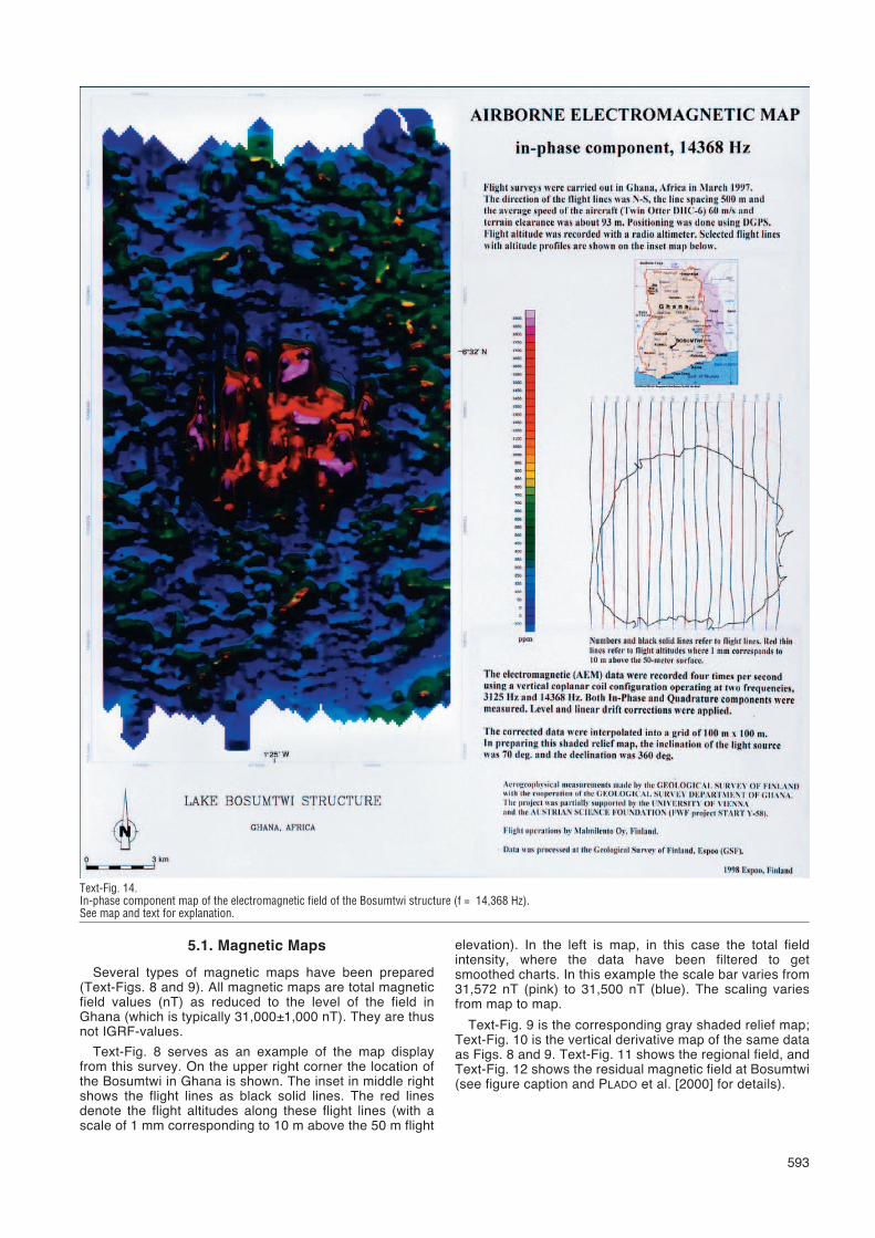
Text-Fig. 14.In-phase component map of the electromagnetic field of the Bosumtwi structure (f = 14,368 Hz).See map and text for explanation.
5.1.1. Magnetic Structure:Example of Interpretations
The magnetic data show a circumferential magnetic halo(h) outside the lakeshore, ~12 km in diameter. The central-north part of the lake reveals a central negative magneticanomaly (c) with smaller positive side-anomalies N and Sof it (n and s, respectively), which is typical for magnetizedbodies at shallow latitudes (cf. Text-Fig. 5; see also JONESet al. (1978).
A few weaker negative magnetic anomalies exist in theeastern and western part of the lake. Together with thenorthern one they seem to encircle a central uplift (cu). Our
model shows that the magnetic anomaly of the structure ispresumably produced by one or several relatively stronglyremanently magnetized impact melt rocks or melt-rich sue-vite bodies.
The new magnetic maps therefore give further supportfor the existence of a central uplift below the lake sedi-ments (see also KARP et al. [2002] and SCHOLZ et al. [2002]for new seismic data that indicate the presence of a centraluplift; also, preliminary gravity data in POHL et al. [in prepa-ration] support this view).
The southern part of the structure lacks prominent mag-netic anomalies. This could be due to landslides or col-
594
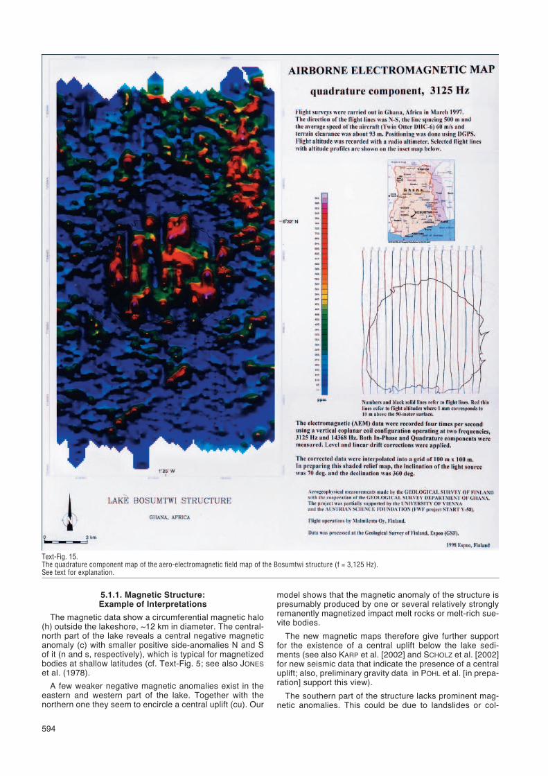
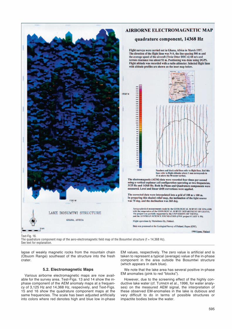
Text-Fig. 15.The quadrature component map of the aero-electromagnetic field map of the Bosumtwi structure (f = 3,125 Hz).See text for explanation.
595
lapse of weakly magnetic rocks from the mountain chain(Obuom Range) southeast of the structure into the freshcrater.
5.2. Electromagnetic Maps
Various airborne electromagnetic maps are now avail-able for the survey area. Test-Figs. 13 and 14 show the in-phase component of the AEM anomaly maps at a frequen-cy of 3,125 Hz and 14,368 Hz, respecively, and Text-Figs.15 and 16 show the quadrature component maps at thesame frequencies. The scale has been adjusted artificiallyinto colors where red denotes high and blue low in-phase
EM values, respectively. The zero value is artificial and istaken to represent a typical (average) value of the in-phasecomponent in the area outside the Bosumtwi structure(which appears in dark blue).
We note that the lake area has several positive in-phaseEM anomalies (pink to red “blocks”).
However, due to the screening effect of the highly con-ductive lake water (cf. TURNER et al., 1996, for water analy-ses) on the measured AEM signal, the interpretation ofthese observed EM-anomalies in the lake is dubious andvery difficult to do in terms of possible structures orimpactite bodies below the water.
Text-Fig. 16.The quadrature component map of the aero-electromagnetic field map of the Bosumtwi structure (f = 14,368 Hz).See text for explanation.
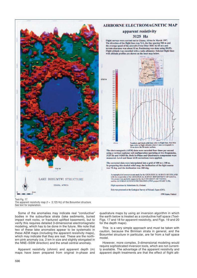
Some of the anomalies may indicate real “conductive”bodies in the subsurface strata (lake sediments, buriedimpact melt rocks, or fractured uplifted basement), but toverify this requires detailed 3-dimensional electromagneticmodeling, which has to be done in the future. We note thattwo of these lake anomalies appear to be systematic inthese AEM maps (including the apparent resistivity maps),which may indicate that they are real. These are the north-ern pink anomaly (ca. 2 km in size and slightly elongated inthe NNE–SSW direction) and the small central anomaly.
Apparent resistivity (ohmm) and apparent depth (m)maps have been prepared from original in-phase and
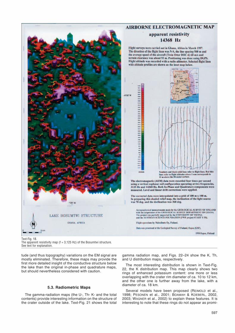
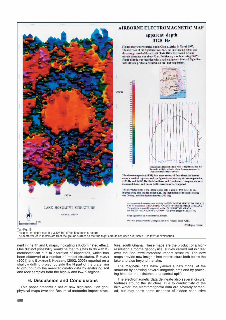
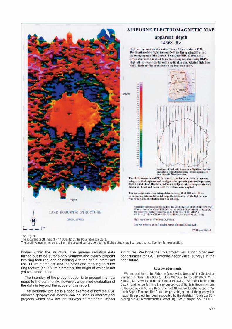
quadrature maps by using an inversion algorithm in whichthe earth below is treated as a conductive half space (Text-Figs. 17 and 18 for apparent resistivity, and Figs. 19 and 20for the depth maps).
This is a very simple approach and must be taken withcaution, because the Birimian strata in general, and theBosumtwi structure in particular, are far from a half spacemodel.
However, more complex, 3-dimensional modeling wouldrequire sophisticated inversion tools, which are not current-ly available. The advantage of the apparent resistivity andapparent depth treatments are that the effect of flight alti-
596
Text-Fig. 17.The apparent resistivity map (f = 3,125 Hz) of the Bosumtwi structure. See text for explanation.
597
tude (and thus topography) variations on the EM signal aremostly eliminated. Therefore, these maps may provide thefirst more detailed insight of the conductive structure belowthe lake than the original in-phase and quadrature maps,but should nevertheless considered with caution.
5.3. Radiometric Maps
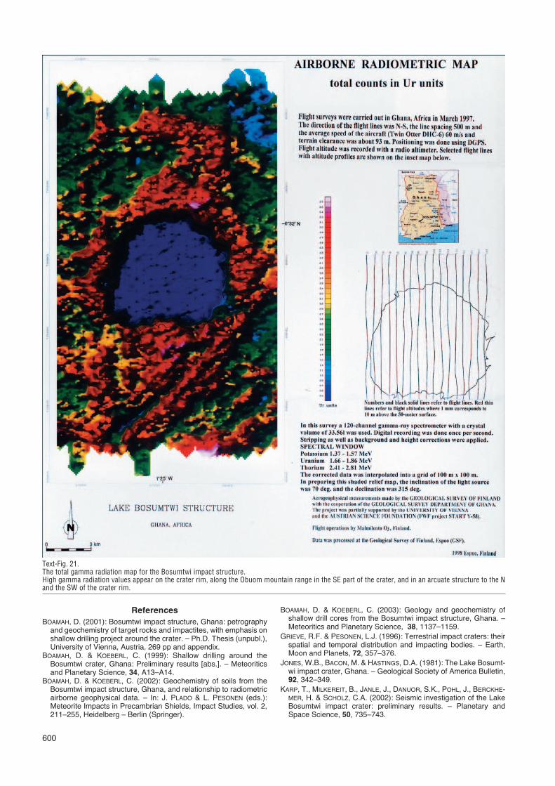
The gamma-radiation maps (the U-, Th- K- and the totalcontents) provide interesting information on the structure ofthe crater outside of the lake. Text-Fig. 21 shows the total
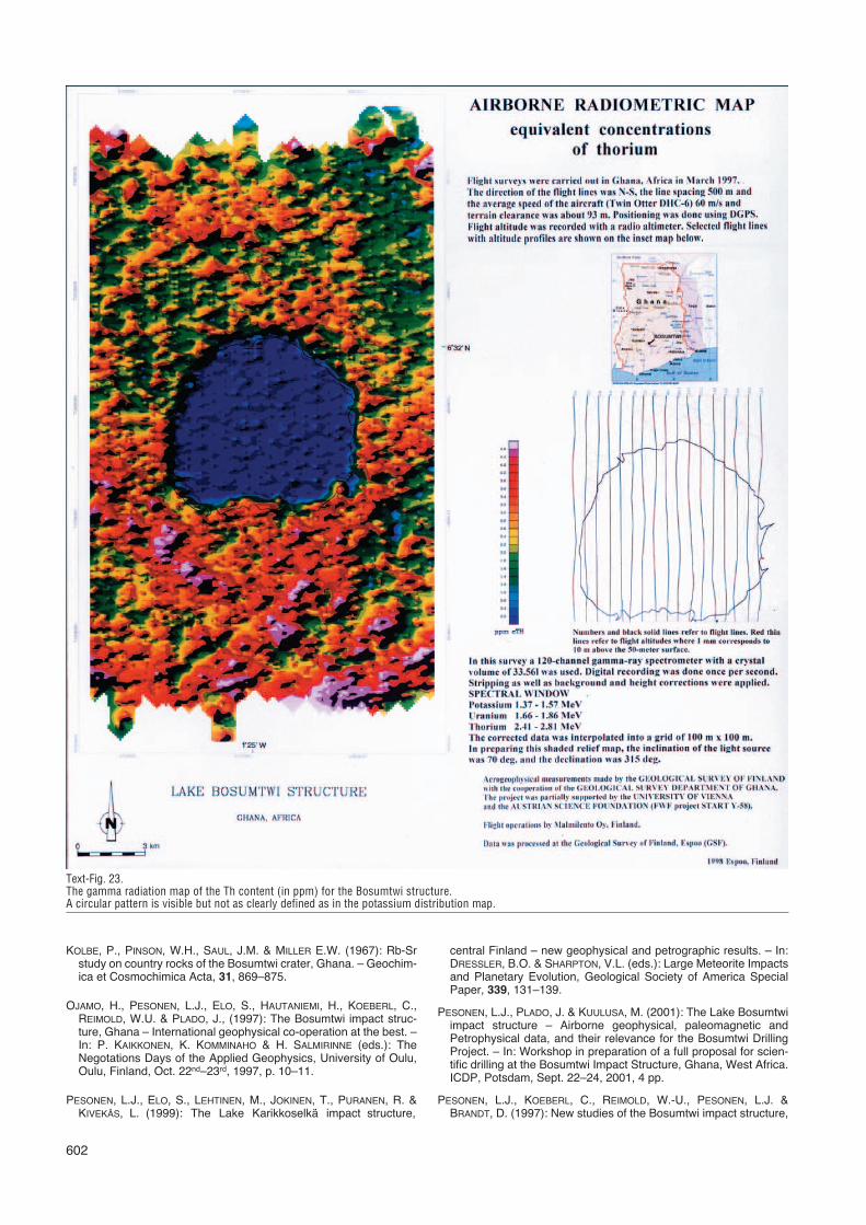
gamma radiation map, and Figs. 22–24 show the K, Th,and U distribution maps, respectively.
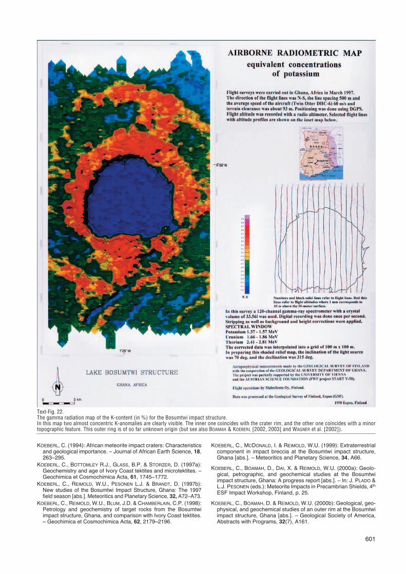
The most interesting distribution is shown in Text-Fig.22, the K distribution map. This map clearly shows tworings of enhanced potassium content: one more or lessoverlapping with the crater rim diameter of ca. 10 to 12 km,and the other one is further away from the lake, with adiameter of ca. 18 km.
Several models have been proposed (REIMOLD et al.,1998; PESONEN et al., 2001; BOAMAH & KOEBERL, 2002,2003; WAGNER et al., 2002) to explain these features. It isinteresting to note that these rings do not appear as promi-
Text-Fig. 18.The apparent resistivity map (f = 3,125 Hz) of the Bosumtwi structure. See text for explanation.
nent in the Th and U maps, indicating a K-dominated effect.One distinct possibility would be that this has to do with K-metasomatism due to alteration of impactites, which hasbeen observed at a number of impact structures. BOAMAH(2001) and BOAMAH & KOEBERL (2002, 2003) reported on ashallow drilling project outside the N part of the crater rimto ground-truth the aero-radiometry data by analyzing soiland rock samples from the high-K and low-K regions.
6. Discussion and ConclusionsThis paper presents a set of new high-resolution geo-
physical maps over the Bosumtwi meteorite impact struc-
ture, south Ghana. These maps are the product of a high-resolution airborne geophysical survey carried out in 1997over the Bosumtwi meteorite impact structure. The newmaps provide new insights into the structure both below thelake and also beyond the lake.
The magnetic data have yielded a new model of thestructure by showing several magnetic rims and by provid-ing hints for the existence of a central uplift.
The electromagnetic data delineate also several circularfeatures around the structure. Due to conductivity of thelake water, the electromagnetic data are severely screen-ed, but may show some evidence of hidden conductive
598
Text-Fig. 19.The apparent depth map (f = 3,125 Hz) of the Bosumtwi structure.The depth values in meters are from the ground surface so that the flight altitude has been subtracted. See text for explanation.
599
bodies within the structure. The gamma radiation dataturned out to be surprisingly valuable and clearly pinpointtwo ring features, one coinciding with the actual crater rim(ca. 11 km diameter), and the other one marking an outerring feature (ca. 18 km diameter), the origin of which is notyet well understood.
The intention of the present paper is to present the newmaps to the community; however, a detailed evaluation ofthe data is beyond the scope of this report.
The Bosumtwi project is a good example of how the GSFairborne geophysical system can be used in internationalprojects which now include surveys of meteorite impact
structures. We hope that this project will launch other newopportunities for GSF airborne geophysical surveys in thenear future.
AcknowledgementsWe are grateful to the Airborne Geophysics Group of the Geological
Survey of Finland (Heli OJAMO, Jukka MULTALA, Jouko VIRONMÄKI, MaijaKURIMO, Kai NYMAN and the late Risto PURANEN). We thank MalmilentoCo., Finland, for performing the aerogeophysical flights in Bosumtwi, andto the Geological Survey Department of Ghana for logistic support. Wethank Seppo ELO and Jüri PLADO for providing some of the geophysicalmaps. This project has been supported by the Austrian “Fonds zur För-derung der Wissenschaftlichen Forschung (FWF)” project Y-58 (to CK).
Text-Fig. 20.The apparent depth map (f = 14,368 Hz) of the Bosumtwi structure.The depth values in meters are from the ground surface so that the flight altitude has been subtracted. See text for explanation.
ReferencesBOAMAH, D. (2001): Bosumtwi impact structure, Ghana: petrography
and geochemistry of target rocks and impactites, with emphasis onshallow drilling project around the crater. – Ph.D. Thesis (unpubl.),University of Vienna, Austria, 269 pp and appendix.
BOAMAH, D. & KOEBERL, C. (1999): Shallow drilling around theBosumtwi crater, Ghana: Preliminary results [abs.]. – Meteoriticsand Planetary Science, 34, A13–A14.
BOAMAH, D. & KOEBERL, C. (2002): Geochemistry of soils from theBosumtwi impact structure, Ghana, and relationship to radiometricairborne geophysical data. – In: J. PLADO & L. PESONEN (eds.):Meteorite Impacts in Precambrian Shields, Impact Studies, vol. 2,211–255, Heidelberg – Berlin (Springer).
BOAMAH, D. & KOEBERL, C. (2003): Geology and geochemistry ofshallow drill cores from the Bosumtwi impact structure, Ghana. –Meteoritics and Planetary Science, 38, 1137–1159.
GRIEVE, R.F. & PESONEN, L.J. (1996): Terrestrial impact craters: theirspatial and temporal distribution and impacting bodies. – Earth,Moon and Planets, 72, 357–376.
JONES, W.B., BACON, M. & HASTINGS, D.A. (1981): The Lake Bosumt-wi impact crater, Ghana. – Geological Society of America Bulletin,92, 342–349.
KARP, T., MILKEREIT, B., JANLE, J., DANUOR, S.K., POHL, J., BERCKHE-MER, H. & SCHOLZ, C.A. (2002): Seismic investigation of the LakeBosumtwi impact crater: preliminary results. – Planetary andSpace Science, 50, 735–743.
600
Text-Fig. 21.The total gamma radiation map for the Bosumtwi impact structure.High gamma radiation values appear on the crater rim, along the Obuom mountain range in the SE part of the crater, and in an arcuate structure to the Nand the SW of the crater rim.
601
KOEBERL, C. (1994): African meteorite impact craters: Characteristicsand geological importance. – Journal of African Earth Science, 18,263–295.
KOEBERL, C., BOTTOMLEY R.J., GLASS, B.P. & STORZER, D. (1997a):Geochemistry and age of Ivory Coast tektites and microtektites. –Geochimica et Cosmochimica Acta, 61, 1745–1772.
KOEBERL, C., REIMOLD, W.U., PESONEN L.J. & BRANDT, D. (1997b):New studies of the Bosumtwi Impact Structure, Ghana: The 1997field season [abs.]. Meteoritics and Planetary Science, 32, A72–A73.
KOEBERL, C., REIMOLD, W.U., BLUM, J.D. & CHAMBERLAIN, C.P. (1998):Petrology and geochemistry of target rocks from the Bosumtwiimpact structure, Ghana, and comparison with Ivory Coast tektites.– Geochimica et Cosmochimica Acta, 62, 2179–2196.
KOEBERL, C., MCDONALD, I. & REIMOLD, W.U. (1999): Extraterrestrialcomponent in impact breccia at the Bosumtwi impact structure,Ghana [abs.]. – Meteoritics and Planetary Science, 34, A66.
KOEBERL, C., BOAMAH, D., DAI, X. & REIMOLD, W.U. (2000a): Geolo-gical, petrographic, and geochemical studies at the Bosumtwiimpact structure, Ghana: A progress report [abs.]. – In: J. PLADO &L.J. PESONEN (eds.): Meteorite Impacts in Precambrian Shields, 4th
ESF Impact Workshop, Finland, p. 25.
KOEBERL, C., BOAMAH, D. & REIMOLD, W.U. (2000b): Geological, geo-physical, and geochemical studies of an outer rim at the Bosumtwiimpact structure, Ghana [abs.]. – Geological Society of America,Abstracts with Programs, 32(7), A161.
Text-Fig. 22.The gamma radiation map of the K-content (in %) for the Bosumtwi impact structure.In this map two almost concentric K-anomalies are clearly visible. The inner one coincides with the crater rim, and the other one coincides with a minortopographic feature. This outer ring is of so far unknown origin (but see also BOAMAH & KOEBERL [2002, 2003] and WAGNER et al. [2002]).
KOLBE, P., PINSON, W.H., SAUL, J.M. & MILLER E.W. (1967): Rb-Srstudy on country rocks of the Bosumtwi crater, Ghana. – Geochim-ica et Cosmochimica Acta, 31, 869–875.
OJAMO, H., PESONEN, L.J., ELO, S., HAUTANIEMI, H., KOEBERL, C.,REIMOLD, W.U. & PLADO, J., (1997): The Bosumtwi impact struc-ture, Ghana – International geophysical co-operation at the best. –In: P. KAIKKONEN, K. KOMMINAHO & H. SALMIRINNE (eds.): TheNegotations Days of the Applied Geophysics, University of Oulu,Oulu, Finland, Oct. 22nd–23rd, 1997, p. 10–11.
PESONEN, L.J., ELO, S., LEHTINEN, M., JOKINEN, T., PURANEN, R. &KIVEKÄS, L. (1999): The Lake Karikkoselkä impact structure,
central Finland – new geophysical and petrographic results. – In:DRESSLER, B.O. & SHARPTON, V.L. (eds.): Large Meteorite Impactsand Planetary Evolution, Geological Society of America SpecialPaper, 339, 131–139.
PESONEN, L.J., PLADO, J. & KUULUSA, M. (2001): The Lake Bosumtwiimpact structure – Airborne geophysical, paleomagnetic andPetrophysical data, and their relevance for the Bosumtwi DrillingProject. – In: Workshop in preparation of a full proposal for scien-tific drilling at the Bosumtwi Impact Structure, Ghana, West Africa.ICDP, Potsdam, Sept. 22–24, 2001, 4 pp.
PESONEN, L.J., KOEBERL, C., REIMOLD, W.-U., PESONEN, L.J. &BRANDT, D. (1997): New studies of the Bosumtwi impact structure,
602
Text-Fig. 23.The gamma radiation map of the Th content (in ppm) for the Bosumtwi structure.A circular pattern is visible but not as clearly defined as in the potassium distribution map.
603
Ghana: the 1997 field season [abs.]. – Meteoritics and PlanetaryScience, 32, A72–73.
PESONEN, L.J., NEVANLINNA, H., LEINO, M.A.H. & RYNS, J. (1994):The Earth’s Magnetic Field Maps of 1990.0. – Geophysica, 30,57–77.
PESONEN, L.J., KOEBERL, C., OJAMO, H., HAUTANIEMI, H., ELO, S. &PLADO, J. (1998): Aerogeophysical studies of the Bosumtwi impactstructure, Ghana [abs.]. – Geological Society of America,Abstracts with Programs, 30(6), A190.
PESONEN, L.J., PLADO, J., KOEBERL, C. & ELO, S. (1999): The LakeBosumtwi meteorite impact structure, Ghana: Magnetic modelling[abs.]. – Meteoritics and Planetary Science, 34, A91–A92.
PILKINGTON, M. & GRIEVE, R.A.F. (1992): The geophysical signatureof terrestrial impact craters. – Rev. of Geophysics, 30, 161–181.
PLADO, J., PESONEN, L.J., KOEBERL, C. & ELO, S. (2000): TheBosumtwi meteorite impact structure, Ghana: A magnetic model. –Meteoritics and Planetary Science, 35, 723–732.
REIMOLD, W.U., BRANDT, D. & KOEBERL, C. (1998): Detailed structur-al analysis of the rim of a large complex impact crater: Bosumtwicrater, Ghana. – Geology, 26, 543–546.
SCHOLZ, C.A, KARP, T., BROOKS, K.M., MILKEREIT, B., AMOAKO,P.Y.A. & ARKO, J.A. (2002): Pronounced central uplift identified inthe Lake Bosumtwi impact structure, Ghana, using multichannelseismic reflection data. – Geology, 30, 939–942.
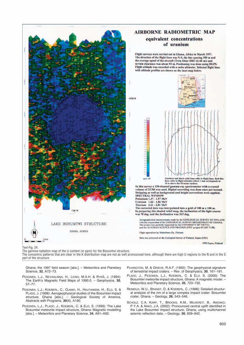
Text-Fig. 24.The gamma-radiation map of the U content (in ppm) for the Bosumtwi structure.The concentric patterns that are clear in the K distribution map are not as well pronounced here, although there are high U regions to the N and in the Spart of the structure.

604
TALBOT, M.R. & DELIBRIAS, G. (1980): A new Late Pleistocene –Holocene water level curve for Lake Bosumtwi, Ghana. – Earthand Planetary Science Letters, 47, 336–344.
TALBOT, M.R. & JOHANNESSEN, T. (1992): A high resolution paleocli-matic record for the last 27,500 years in tropical West Africa fromthe carbon and nitrogen isotopic composition of lacustrine organicmatter. – Earth and Planetary Science Letters, 110, 23–37.
TALBOT, M.R., LIVINGSTON, D.A., PALMER, P.A., MALEY, J., MELACK,J.M., DELIBRIAS, G. & GULLIKSEN, S. (1984): Preliminary resultsfrom sediment cores from Lake Bosumtwi, Ghana. – Paleoecologyof Africa and the Surrounding Islands, 16, 173–192.
TURNER, B.F., GARDNER, L.R., SHARP, W.E. & BLOOD, E.R. (1996):The geochemistry of Lake Bosumtwi, a hydrologically closed basinin the humid zone of tropical Ghana. – Limnology and Oceanogra-phy, 41, 1415–1424.
WAGNER, R., REIMOLD, W.U. & BRANDT, D. (2002): Bosumtwi impactcrater, Ghana: A remote sensing investigation. – In: PLADO, J. &PESONEN, L.J. (eds.): Meteorite Impacts in Precambrian Shields.Impact Studies, vol. 2, 189–210, Heidelberg (Springer ).
Manuskript bei der Schriftleitung eingelangt am 6. November 2003