Embed Size (px)
DESCRIPTION
JBL 6ch Amplifier GTO Series 755.6 instruction and installation manual.
Citation preview

GTO Series 755.6 755.6II
6 CHANNEL POWER AMPLIFIERS
SERVICE MANUAL
JBL Consumer Products 250 Crossways Park Dr.
Woodbury, New York 11797 Rev4VV3/2009
- CONTENTS -
SPECIFICATIONS ………………………………….……..1 FEATURES/TEST CONDITIONS……..….………………2 INSTALLATION………………….……...……..…...…...…3 CONNECTIONS………………….……...……..…...…..…4 SET-UP/CONTROLS ……..…………….…..…….….…...6 INSTALLING NEON TUBES..…….……..………………..6 BASIC TROUBLESHOOTING..…….….….………………7 TYPICAL SYSTEM WIRING..…….……..……………..…8 EXPLODED VIEW/PARTS LIST…….….…..…………....9 MECHANICAL PARTS LIST……………………………..10 AMPLIFIER BLOCK DIAGRAM…………………….……11 P.C.B. DRAWINGS….……………………………….…….12 ELECTRICAL PARTS LIST ..……….……….…….….…16 VERSION II ELECTRICAL PARTS LIST ADDENDUM….……….20 IC/TRANSISTOR PINOUTS..……..….…….….….….…..21 GTO755.6 SCHEMATICS………………………...……...24 GTO755.6II SCHEMATICS………..……….……..……...28 PACKING……..…………………………………………....32
GTO 755.6/ GTO 755.6II Specifications Output Power: 60W RMS x 4 channels; 107W RMS x 2 channels (14.4V supply) @ 4 ohms; ≤1% THD + N
80W RMS x 4 channels; 150W x 2 channels @ 2 ohms; ≤1% THD + N 160W RMS x 2 channels; 300W x 1 channel @ 4 ohms; ≤1% THD + N
Signal-to-noise ratio: 79dBA (reference 1W into 4 ohms) Dynamic power: 117W (channels 1,2,3,4) @ 2 ohms 163W (channels 5,6) @ 2 ohms Effective damping factor: 6.39 @ 4 ohms Frequency response: 10Hz – 47kHz (–3dB) (channels 1,2,3,4) 10Hz – 302Hz (channels 5,6) Maximum input signal: 6.0V Maximum sensitivity: GTO 755.6 - 250mV GTO 755.6II - 75mV DC Offset <50mV (-50%) Output regulation: .042dB @ 4 ohms Idle Current 1.9A Input Impedance 22kΩ Max Current Draw 50A @ 4 ohms 89A @ 2 ohms Dimensions: 18 11/16 x 12 5/16 x 2 3/8” (L x W x D) (474mm x 313mm x 60mm) Fuses: 30A x 2
JBL continually strives to update and improve existing products, as well as create new ones. The specifications and details in this and related JBL publications are therefore subject to change without notice.
Power Amplifier GTO 755.6/755.6II
1
755.6/755.6II
2
INSTALLATION
2
WARNING: Playing loud music in anautomobile can hinder your ability to heartraffic and permanently damage your hearing. We recommend listening at low ormoderate levels while driving your car. JBLaccepts no liability for hearing loss, bodilyinjury or property damage resulting fromthe use or misuse of this product.
IMPORTANT: To get the best performance from your JBL Grand Touring®
Series amplifiers, we strongly recommendthat installation be entrusted to a qualified professional. Although these instructionsexplain how to install GTO amplifiers in ageneral sense, they do not show specificinstallation methods that may be requiredfor your particular vehicle. If you do nothave the necessary tools or experience, do not attempt the installation yourself.Instead, please ask your authorized JBLcar audio dealer about professional installation.
INSTALLATION WARNINGS AND TIPS• Always wear protective eyewear when
using tools.• Turn off the audio system and other
electrical devices before you start.Disconnect the (–) negative lead fromyour vehicle’s battery.
• Check clearances on both sides of a planned mounting surface beforedrilling any holes or installing anyscrews. Remember that the screws can extend behind the surface.
• At the installation sites, locate andmake a note of all fuel lines, hydraulicbrake lines, vacuum lines and electricalwiring. Use extreme caution when cut-ting or drilling in and around these areas.
• Before drilling or cutting holes, use autility knife to remove unwanted fabricor vinyl to keep material from snaggingin a drill bit.
• When routing cables, keep input-signalcables away from power cables andspeaker wires.
• When making connections, make certain they are secure and properlyinsulated.
• If the amplifier’s fuse must be replaced,use only the same type and rating asthat of the original. Do not substituteanother kind.
CHOOSING A LOCATIONAND MOUNTING THEAMPLIFIERChoose a mounting location in the trunk or cargo area where the amplifier will notbe damaged by shifting cargo. Amplifiercooling is essential for proper amplifieroperation. If the amplifier is to be installedin an enclosed space, make sure there issufficient air circulation for the amplifier to cool itself.
When mounting the amplifier under a seat, ensure that it is clear of all movingseat parts and does not affect the seat adjustments. Mount the amplifier so it is not damaged by the feet of backseat passengers. Make sure that the amplifieris mounted securely using nuts and boltsor the supplied mounting screws.
Mount the amplifier so that it remains dry – never mount an amplifier outside the vehicle or in the engine compartment.
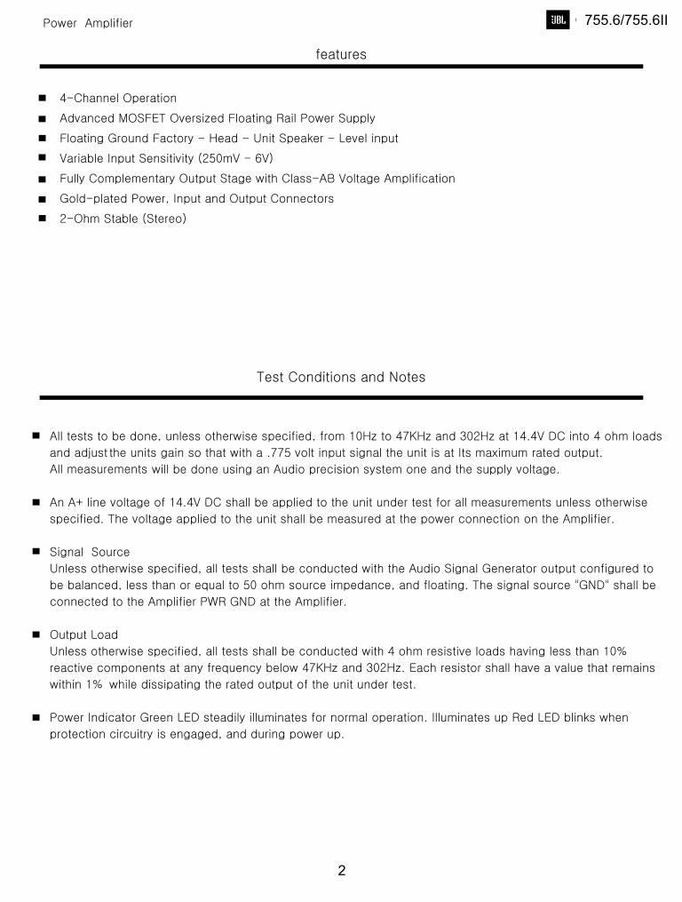
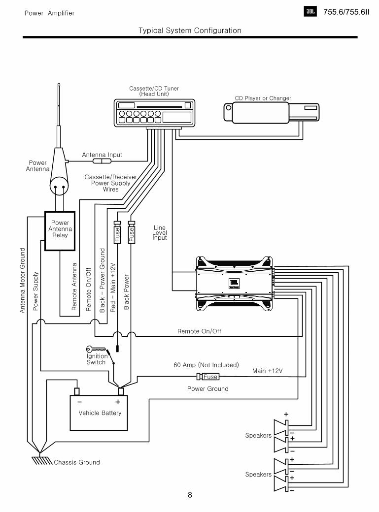
POWER CONNECTIONSThe GTO amplifiers are capable of delivering extremely high power levels,and require a heavy-duty and reliable connection to the vehicle’s electrical systemin order to perform optimally. See Figure 1for connection location. Please adhere tothe following instructions carefully:
Ground ConnectionConnect the amplifier’s Ground (GND) terminal to a solid point on the vehicle’smetal chassis, as close to the amplifier as possible. Refer to the chart below to determine minimum wire-gauge size. Scrapeaway any paint from this location; use a star-type lock washer to secure the connection.
Power ConnectionConnect a wire (see chart at right forappropriate gauge) directly to the vehicle’spositive battery terminal, and install anappropriate fuse holder within 18" of thebattery terminal. Do not install the fuse atthis time. Route the wire to the amplifier’slocation, and connect it to the amplifier’sPositive (+12V) terminal. Be sure to useappropriate grommets whenever routingwires through the firewall or other sheetmetal. Failure to adequately protect thepositive wire from potential damage mayresult in a vehicle fire. When you are done routing and connecting this wire, you mayinstall the fuse at the battery.
Remote ConnectionConnect the amplifier’s Remote (REM) terminal to the source unit’s Remote Turn-On lead using a minimum of 18-gauge wire.
NOTE: When using the speaker levelinputs, connect the remote (REM) terminalto the source unit. If your source unit doesnot have a remote turn-on connection,connect the amplifier’s (REM) terminal tothe vehicle’s accessory circuit.
Speaker ConnectionsRefer to the application guides on thepages that follow. Speaker connectionsshould be made using a minimum of 16-gauge wire.
High-Level Input ConnectionsThe GTO series amplifiers are equipped with speaker-levelinputs that allow you to add an amplifier to head units that do not have RCA lineoutputs. The speaker outputs for thesource unit should be connected to theamplifier using the supplied connector(square four-wire plug). Remember tocheck for proper polarity.
NOTE: When using the high-level inputs,the AUX outputs can be used to pass aline-level signal to another amplifier.
Wire Gauge ChartAmplifier Maximum Minimum Model Current Draw Wire GaugeAWGGTO755.6 87A #8 AWGThese recommendations assume 7' – 10'wire runs. If your installation differs mark-edly, you will need to adjust the wiregauge accordingly.
IMPORTANT NOTE: If you are planning to use optional neon tubes, install thembefore making any electrical connectionsto the amplifier (refer to“Installing NeonTubes” ).
Figure 1. Terminal connection end plate.
GTO Amp OM 2/3/04 3:54 PM Page 2
755.6/755.6II
3
Subwoofer Rear Front
–
+
+
–+
–
5
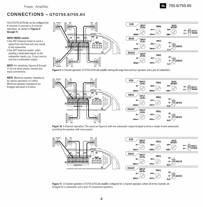
CONNECTIONS – GTO755.6/755.6II
The GTO755.6/755.6II can be configured for 6-channel, 5-channel or 3-channeloperation, as shown in Figures 9through 11.
INPUT MODE switch:• Use INT (internal mode) to send a
signal from the front and rear inputs to the subwoofer.
• Use EXT (external mode) whensending a dedicated signal to the subwoofer inputs; e.g., if your sourceunit has a subwoofer output.
NOTE: For simplicity, Figures 9 through11 do not show power, remote andinput connections.
NOTE: Minimum speaker impedancefor stereo operation is 2 ohms.Minimum speaker impedance forbridged operation is 4 ohms.
Subwoofer Rear Front
Subwoofer Rear Front
–
+
–
+
+
–
+
–
+
–
+
–
Figure 9. 6-Channel operation: GTO755.6/755.6II amplifier driving full-range front and rear speakers and a pair of subwoofers.
Subwoofer Rear Front
Rear Front
–
+
–
+
+
–
+
–
+
–
Figure 10. 5-Channel operation: The same as Figure 9, with the subwoofer output bridged to drive a single 4-ohm subwoofer, providing the speaker with more power.
Figure 11. 3-Channel operation: GTO755.6/755.6II amplifier configured for 3-channel operation, where all of the channels arebridged for a subwoofer and a pair of component speakers.
GTO Amp OM 2/3/04 3:54 PM Page 5
755.6/755.6II
4
755.6/755.6II
5
6
INSTALLATION AND SETUP
SETTING THECROSSOVER(S)Determine your system plans and set thecrossover mode switch accordingly. If youplan to use the GTO75.2 or GTO75.4 to drivefull-range speakers, set the crossovermode to FLAT and skip to “Setting InputSensitivity.”
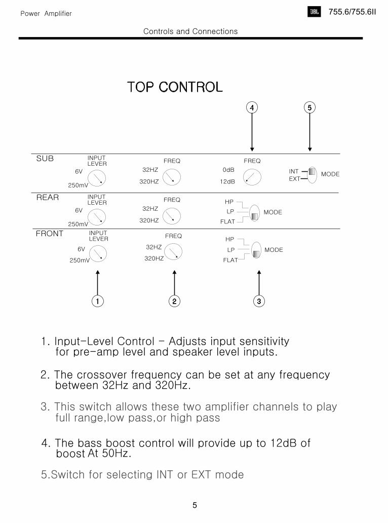
Initially set the crossover frequency control midway. While listening to music,adjust the crossover for the least perceived distortion from the speakers,allowing them to reproduce as much bass as possible.
Systems using a separate subwoofer setthe crossover mode to HP (high pass) foryour full-range speakers. Adjust thecrossover frequency to limit bass and provide increased system volume with less distortion.
For subwoofers, choose the highest frequency that removes vocal informationfrom the sound of the subwoofer.
If using the GTO75.2 or GTO75.4 to drive a subwoofer(s), set the crossover mode toLP (low pass).
NOTE:The subwoofer output of the GTO755.6 is low-pass only and does not have acrossover mode switch.
SETTING INPUTSENSITIVITY1. Initially turn the INPUT LEVEL control(s)
to minimum (counter clockwise).2. Reconnect the (–) negative lead to the
vehicle’s battery. Apply power to theaudio system and play a dynamic musictrack.
3. On the source unit, increase the volumecontrol to 3/4 volume. Slowly increasethe INPUT LEVEL control(s) toward threeo’clock until you hear slight distortion in the music. Then reduce the INPUTLEVEL slightly until distortion is no longer heard.
NOTE: After the source unit is on, red LEDs(on the top panel) will light, indicating theamplifier is on. If not, check the wiring,especially the remote connection from thesource unit. Also refer to “Troubleshooting”on the next page.
REMOTE LEVEL CONTROLAll GTO subwooferamplifiers have inputs for an optionalremote level control (RLC). This will allowthe amplifier’s input level to be adjustedfrom the listening position. Connect theoptional remote level control using the RJ-11 jack on the side of the amplifier.Install the control module in the front ofthe vehicle within easy reach of the driver.Under the dash or in the center consoleare both suitable locations.
SETTING THE BASS BOOSTThe GTO755.6/755.6II is equipped with a bass-boost control. This allows you to adjust thebass output of your system at 50Hz up to12dB and enhance low frequency.
AUX OUTPUT
NOTE:
INSTALLING NEON TUBES(OPTIONAL) 1. Using a Phillips screwdriver, remove all
screws on the amplifier’s output/powerend panel and set them aside.
2. Using a 3 ⁄32-inch Allen wrench, removeonly the screws on the amplifier’s (top)clear cover and set them aside.
3. Remove the end panel and slide thecover off. Set both parts aside.
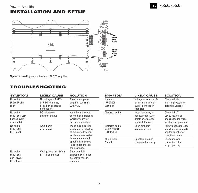
4. Locate the enclosed hardware bag andremove the four clips. Each clip has asquare end and a larger round end.Using a round end, press two clips ontoeach neon tube (e.g., Street Glow AN9 or equivalent), as shown in Figure 13.
5. For each tube, align both clips so thesquare ends slide onto an exposedextrusion edge, as shown in Figure 9. Do not cover any screw holes. Wheninstalled correctly, each neon tube willsit under an extrusion and not be visiblewhen viewed from directly above.
6. Route each neon tube’s power cablethrough its respective NEON hole on theend panel (see Figure 13).
7. Slide the cover back into place and re-install its screws. Then, replace the endpanel and reinstall its screws.
8. Finish the installation of the neon tubesas instructed in their owner’s manual.
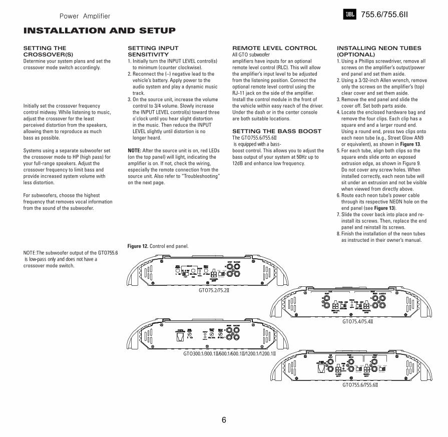
Figure 12. Control end panel.
GTO75.2/75.2II
GTO75.4/75.4II
GTO300.1/300.1II/600.1/600.1II/1200.1/1200.1II
GTO755.6/755.6II
GTO Amp OM 2/3/04 3:54 PM Page 6
755.6/755.6II
6
7
INSTALLATION AND SETUP
To NeonPowerSupply
To NeonPowerSupply
Figure 13. Installing neon tubes in a JBL GTO amplifier.
TROUBLESHOOTING
SYMPTOM LIKELY CAUSE SOLUTION
No audio No voltage at BATT+ Check voltages at(POWER LED or REM terminals, amplifier terminalsis off) or bad or no ground with VOM
connectionNo audio DC voltage on Amplifier may need(PROTECT LED amplifier output service; see enclosedflashes every warranty card for4 seconds) service information No audio Amplifier is Make sure amplifier(PROTECT overheated cooling is not blockedLED is on) at mounting location;
verify speaker systemimpedance is within specified limits (see “Specifications” on the next page)
No audio Voltage less than 9V on Check vehicle(PROTECT BATT+ connection charging system forand POWER defective voltage LEDs flash) regulator
SYMPTOM LIKELY CAUSE SOLUTION
No audio Voltage more than 16V Check vehicle(PROTECT or less than 8.5V on charging system forLED is on) BATT+ connection defective voltage
regulatorDistorted audio Input sensitivity is Check INPUT
not set properly, or LEVEL setting; oramplifier or source check speaker wiresunit is defective for shorts or grounds
Distorted audio Short circuit in Remove speaker leadsand PROTECT speaker or wire one at a time to locateLED flashes shorted speaker or
wire, then repair Music lacks Speakers are not Check speaker“punch” connected properly connections for
proper polarity
GTO Amp OM 2/3/04 3:54 PM Page 7
755.6/755.6II
7
Grand TouringGrand Touring
755.6/755.6II
8
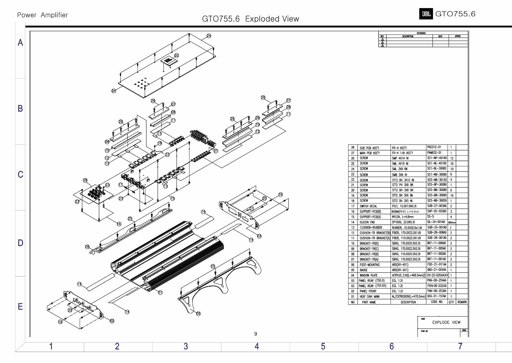
9
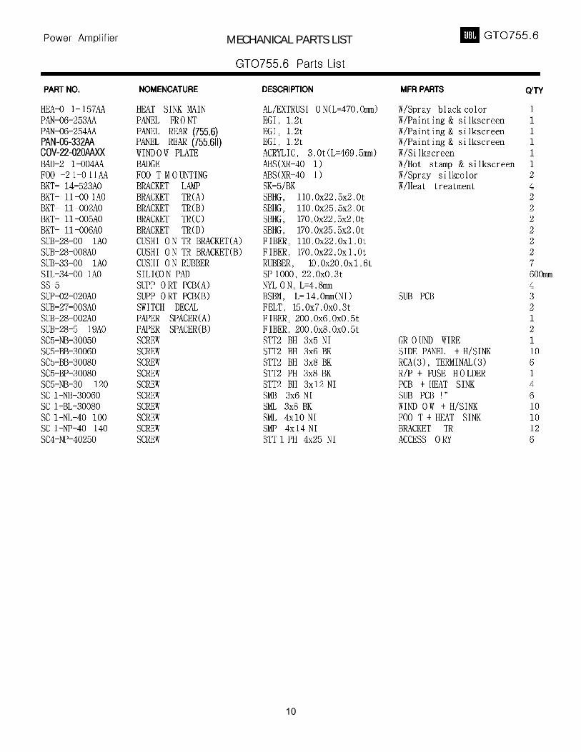
MECHANICAL PARTS LIST
10
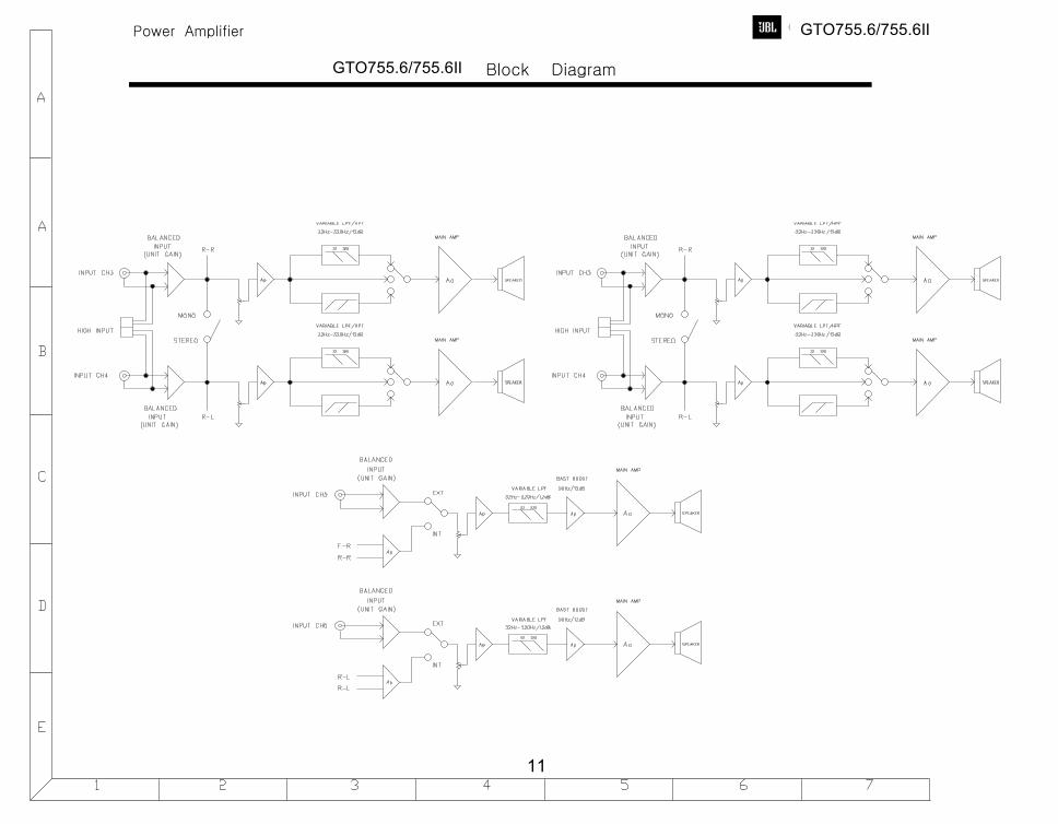
GTO755.6/755.6II
GTO755.6/755.6II
11
GTO755.6/755.6II
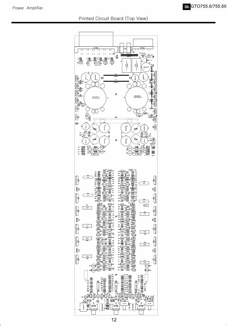
12
GTO755.6/755.6II
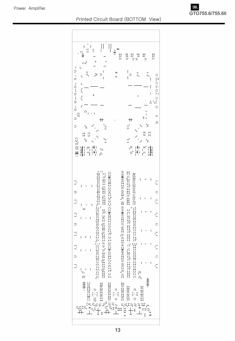
13
GTO755.6/755.6II
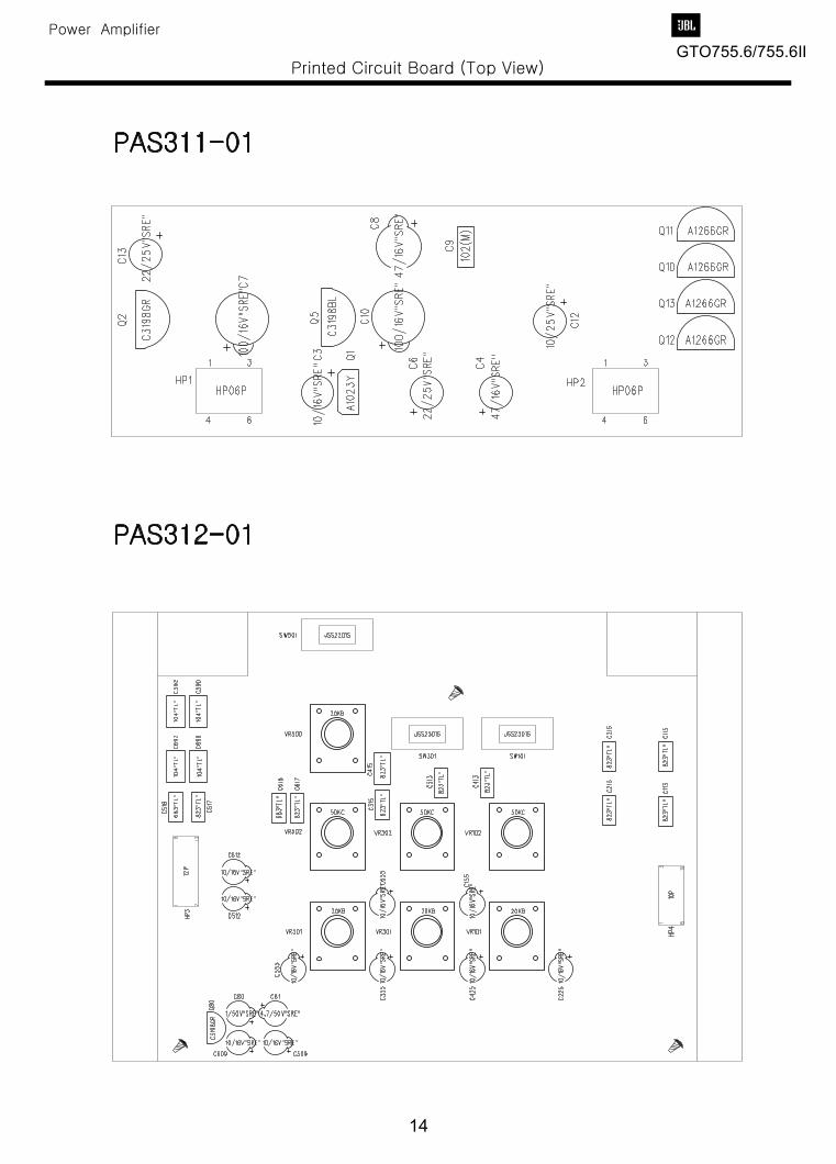
14
GTO755.6/755.6II
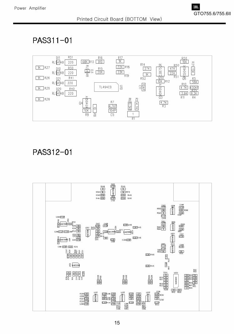
15
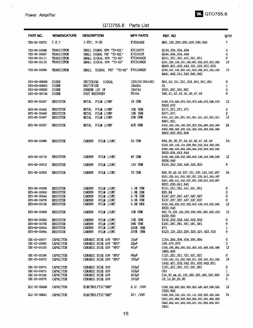
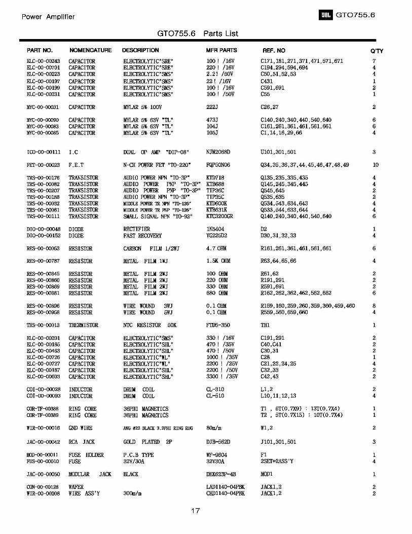
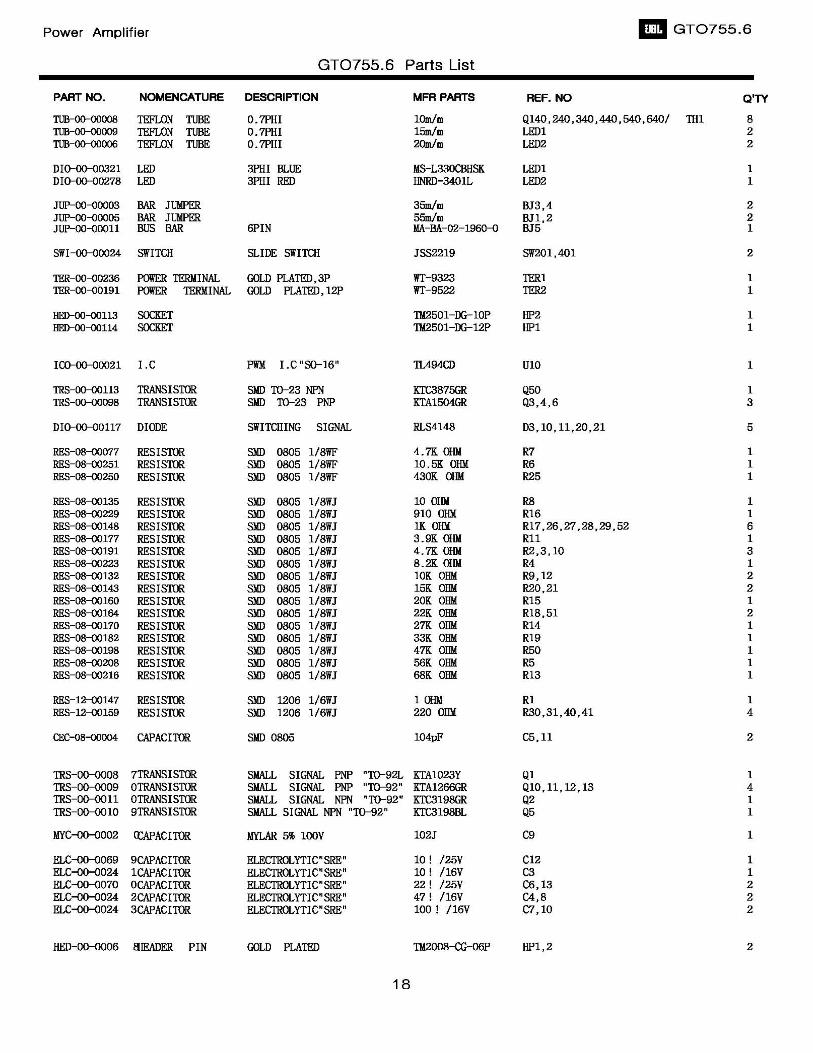
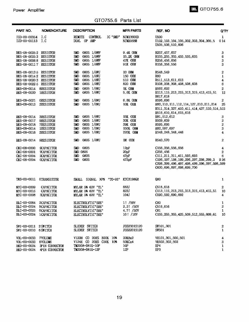
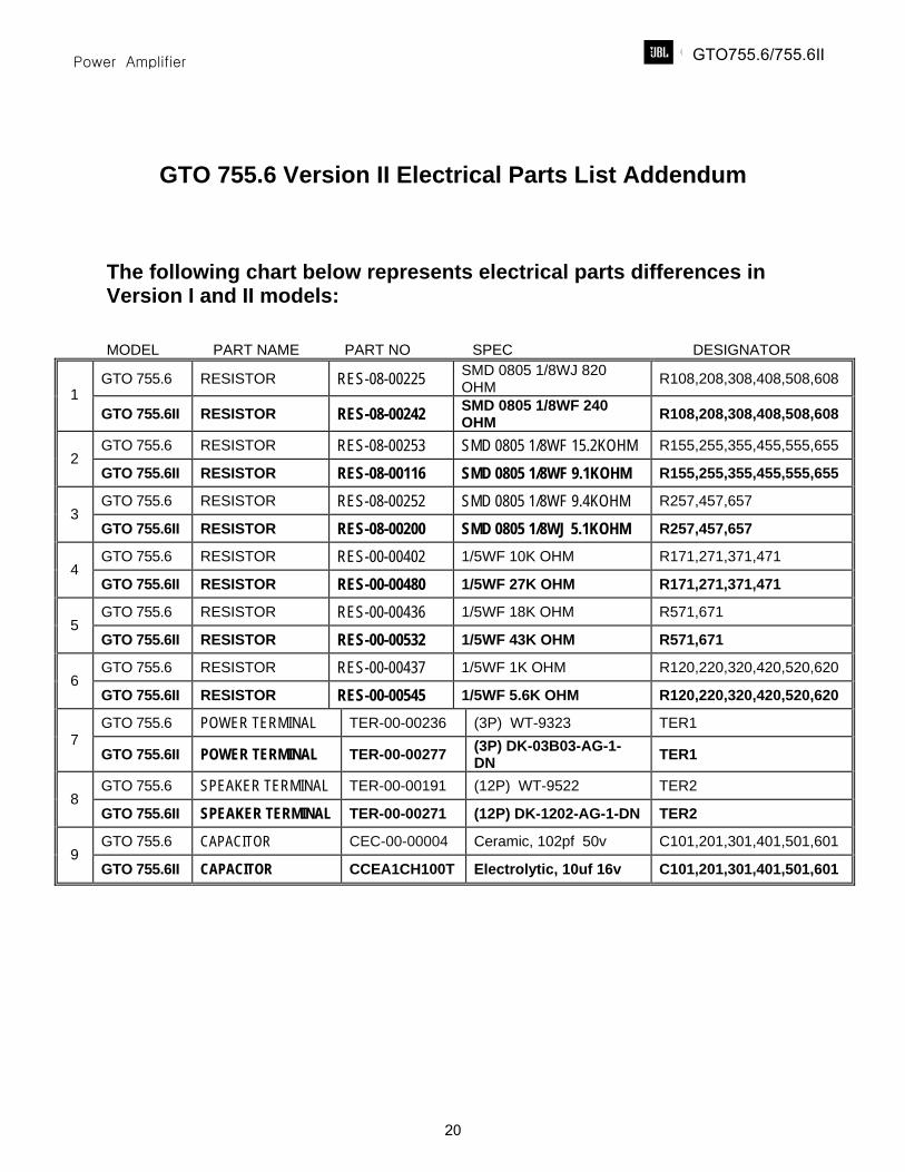
GTO 755.6 Version II Electrical Parts List Addendum
The following chart below represents electrical parts differences in Version I and II models: MODEL PART NAME PART NO SPEC DESIGNATOR
GTO 755.6 RESISTOR RES-08-00225 SMD 0805 1/8WJ 820 OHM R108,208,308,408,508,608
1 GTO 755.6II RESISTOR RES-08-00242 SMD 0805 1/8WF 240
OHM R108,208,308,408,508,608
GTO 755.6 RESISTOR RES-08-00253 SMD 0805 1/8WF 15.2KOHM R155,255,355,455,555,655 2
GTO 755.6II RESISTOR RES-08-00116 SMD 0805 1/8WF 9.1KOHM R155,255,355,455,555,655
GTO 755.6 RESISTOR RES-08-00252 SMD 0805 1/8WF 9.4KOHM R257,457,657 3
GTO 755.6II RESISTOR RES-08-00200 SMD 0805 1/8WJ 5.1KOHM R257,457,657
GTO 755.6 RESISTOR RES-00-00402 1/5WF 10K OHM R171,271,371,471 4
GTO 755.6II RESISTOR RES-00-00480 1/5WF 27K OHM R171,271,371,471
GTO 755.6 RESISTOR RES-00-00436 1/5WF 18K OHM R571,671 5
GTO 755.6II RESISTOR RES-00-00532 1/5WF 43K OHM R571,671
GTO 755.6 RESISTOR RES-00-00437 1/5WF 1K OHM R120,220,320,420,520,620 6
GTO 755.6II RESISTOR RES-00-00545 1/5WF 5.6K OHM R120,220,320,420,520,620
GTO 755.6 POWER TERMINAL TER-00-00236 (3P) WT-9323 TER1 7
GTO 755.6II POWER TERMINAL TER-00-00277 (3P) DK-03B03-AG-1-DN TER1
GTO 755.6 SPEAKER TERMINAL TER-00-00191 (12P) WT-9522 TER2 8
GTO 755.6II SPEAKER TERMINAL TER-00-00271 (12P) DK-1202-AG-1-DN TER2
GTO 755.6 CAPACITOR CEC-00-00004 Ceramic, 102pf 50v C101,201,301,401,501,601 9
GTO 755.6II CAPACITOR CCEA1CH100T Electrolytic, 10uf 16v C101,201,301,401,501,601
GTO755.6/755.6II
20
GTO755.6/755.6II
21
GTO755.6/755.6II
22
GTO755.6/755.6II
23
71 2 3 4 5 6 8
A
B
C
D
E
12V
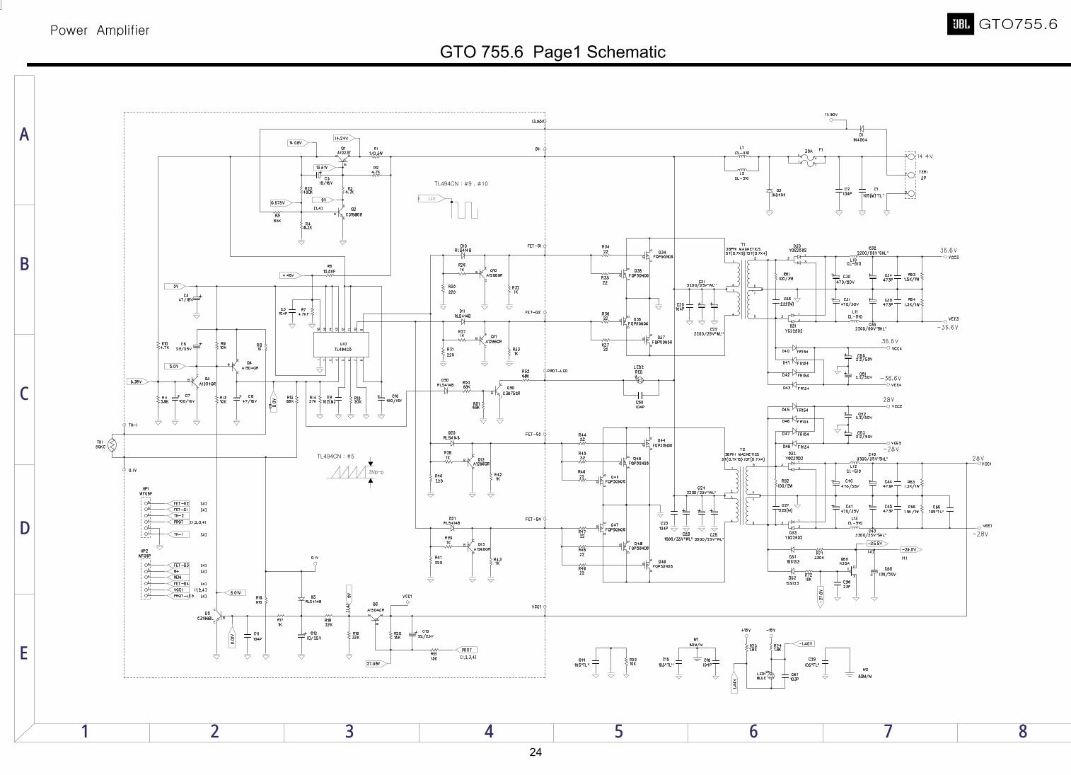
GTO 755.6 Page1 Schematic
24
71 2 3 4 5 6 8
A
B
C
D
E
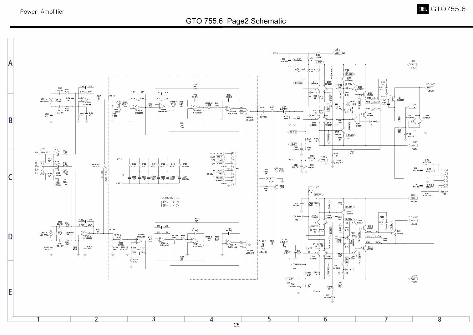
GTO 755.6 Page2 Schematic
25
71 2 3 4 5 6 8
A
B
C
D
E
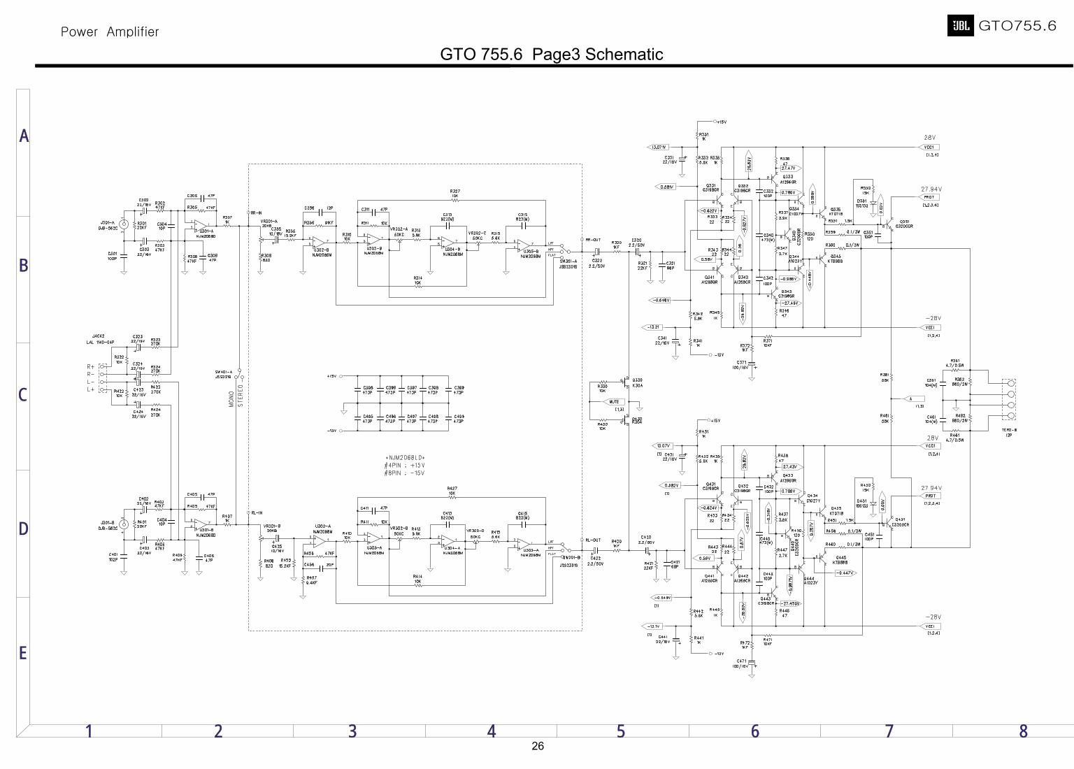
GTO 755.6 Page3 Schematic
26
71 2 3 4 5 6 8
A
B
C
D
E
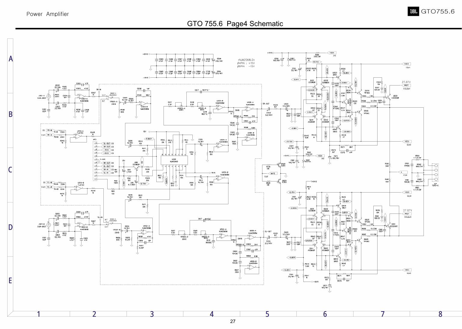
GTO 755.6 Page4 Schematic
27
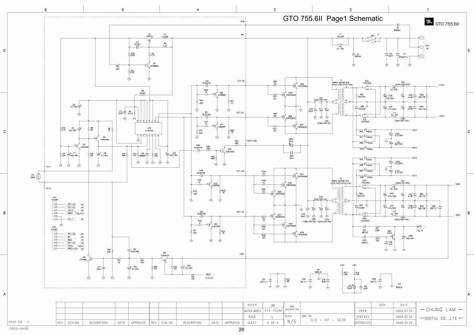
GTO 755.6II Page1 Schematic GTO 755.6II
28
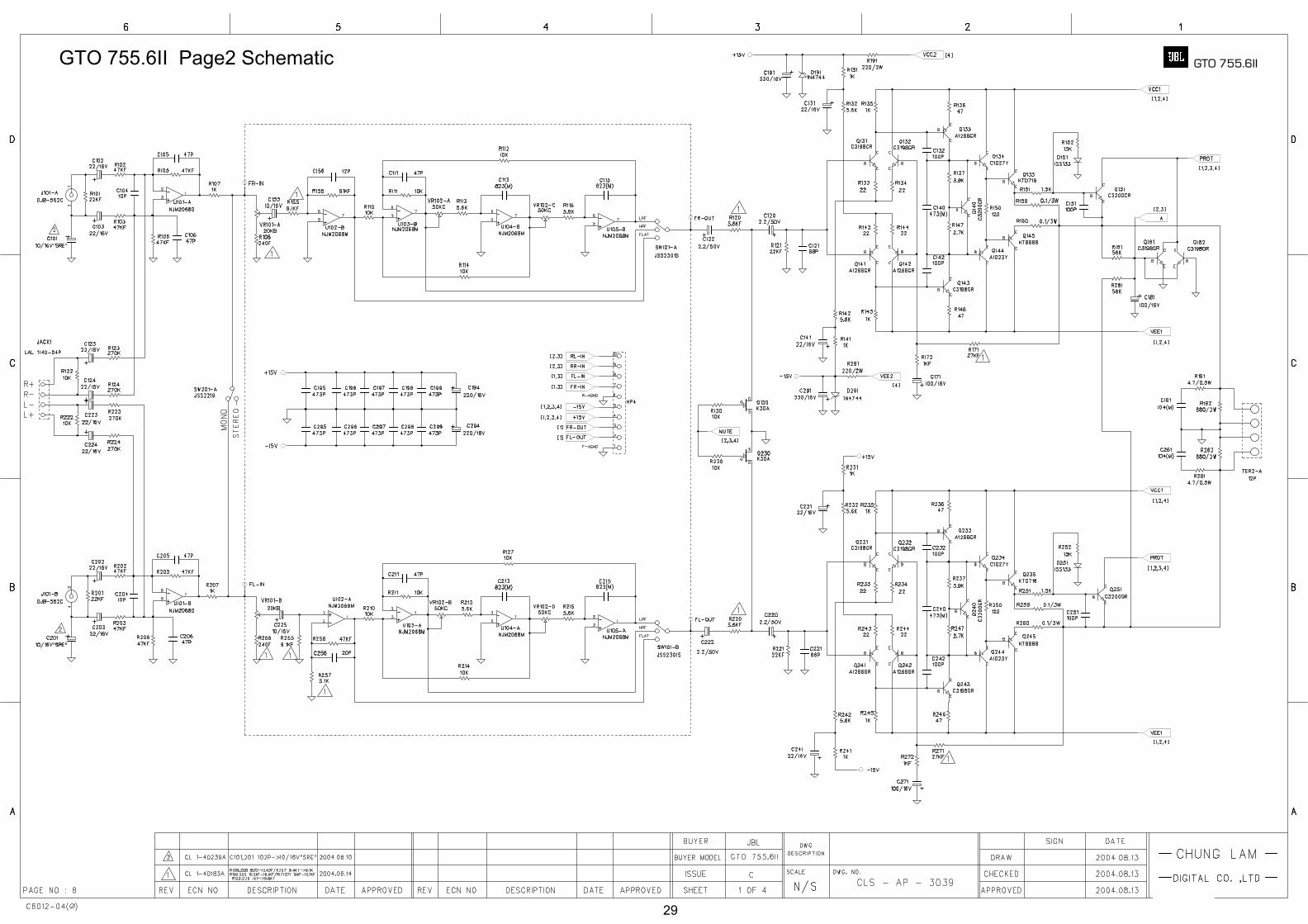
GTO 755.6II Page2 Schematic GTO 755.6II
29
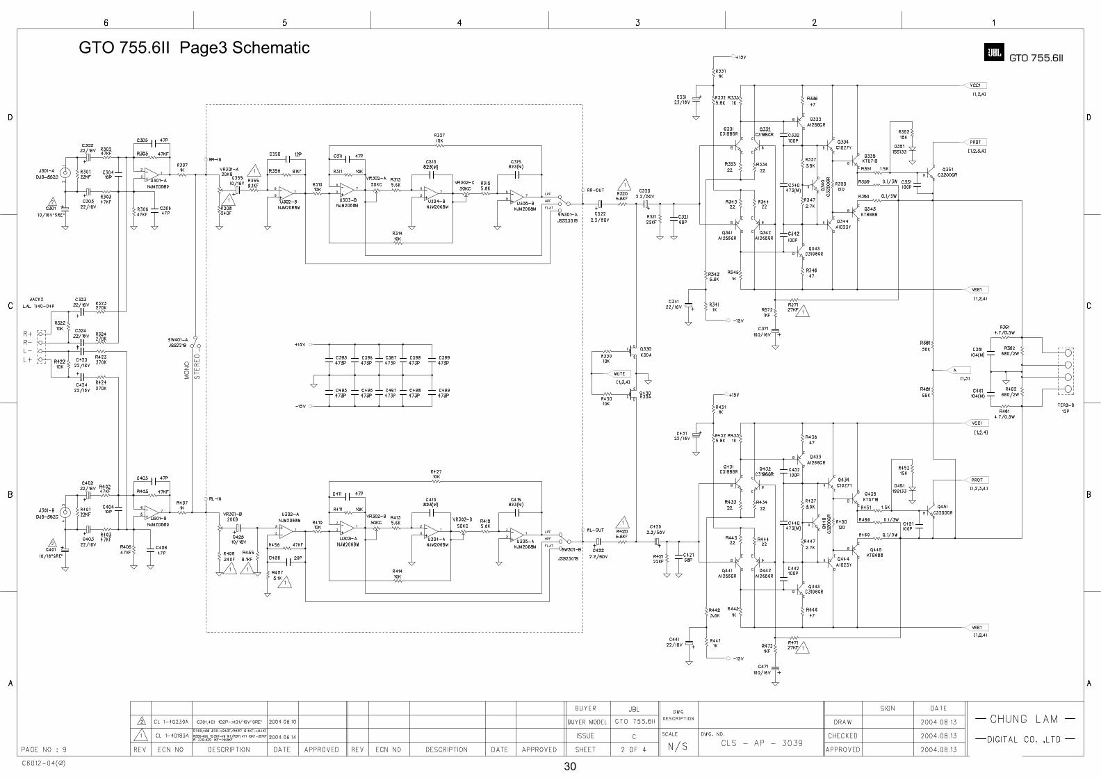
GTO 755.6II Page3 Schematic GTO 755.6II
30
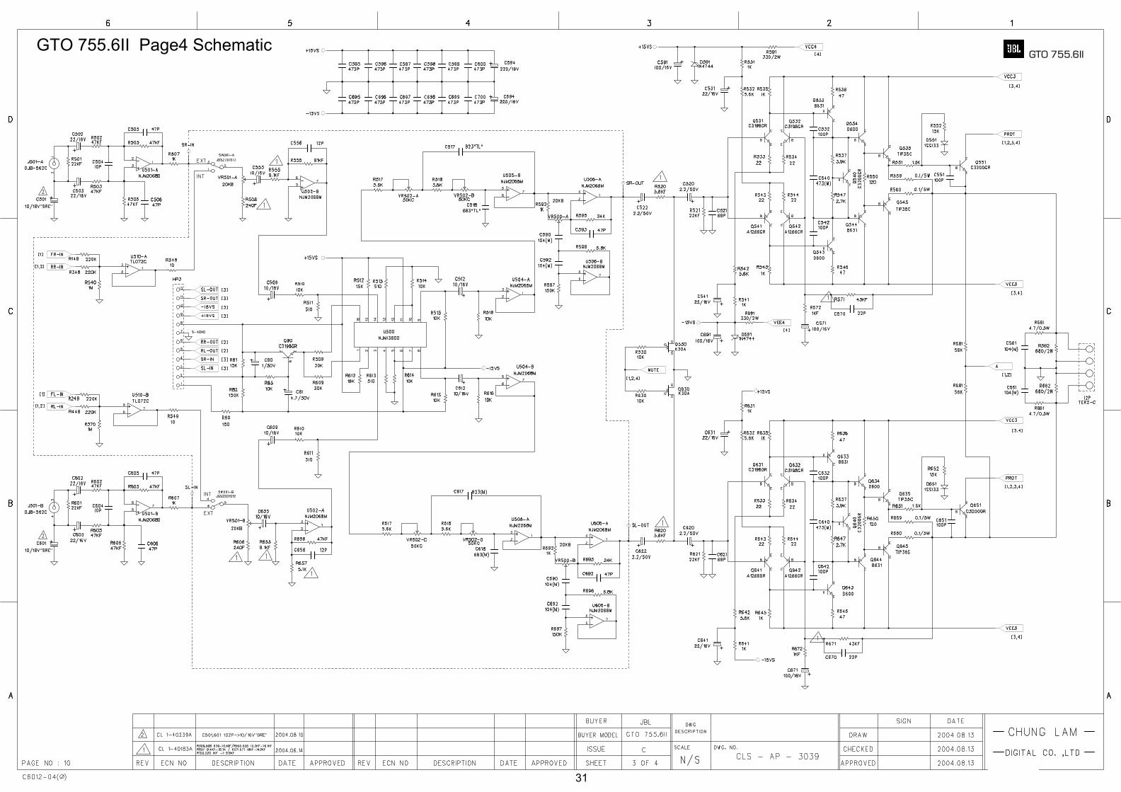
GTO 755.6II Page4 Schematic GTO 755.6II
31
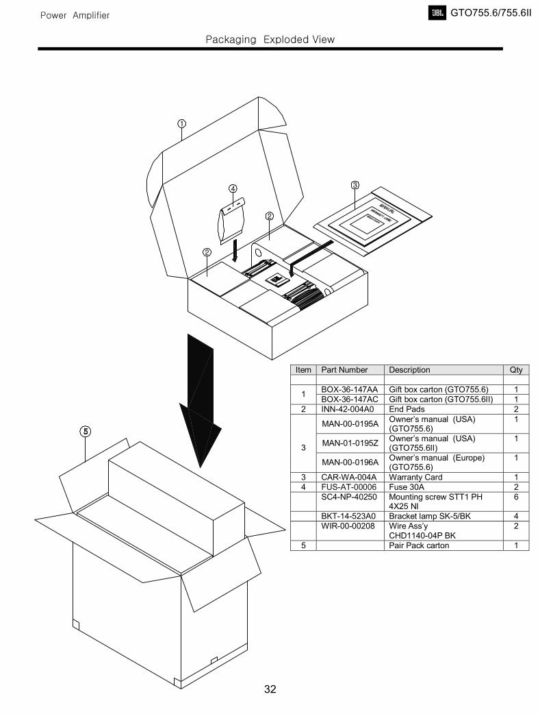
Item Part Number Description Qty
BOX-36-147AA Gift box carton (GTO755.6) 1 1 BOX-36-147AC Gift box carton (GTO755.6II) 1 2 INN-42-004A0 End Pads 2
MAN-00-0195A Owner’s manual (USA) (GTO755.6)
1
MAN-01-0195Z Owner’s manual (USA) (GTO755.6II)
1 3
MAN-00-0196A Owner’s manual (Europe) (GTO755.6)
1
3 CAR-WA-004A Warranty Card 1 4 FUS-AT-00006 Fuse 30A 2 SC4-NP-40250 Mounting screw STT1 PH
4X25 NI 6
BKT-14-523A0 Bracket lamp SK-5/BK 4 WIR-00-00208 Wire Ass’y
CHD1140-04P BK 2
5 Pair Pack carton 1
GTO755.6/755.6II
32