Embed Size (px)
Citation preview

JetStream PC Programming
User’s Guide
CentraLite Systems, Inc. | 6420 Wall Street | Mobile, AL 36695 | 877.466.5483 | 251.607.9119

Table of Contents
Introduction ..................................................................................................................................1
Warnings and Regulatory Compliance ..................................................................................2
Product Overview ........................................................................................................................3
Components..................................................................................................................................4
Detailed Description of Components ....................................................................................5
USB Programming Bridge ....................................................................................................5
Wall Mounted Dimmer..........................................................................................................5
Lamp Module..........................................................................................................................6
Wall Mounted Keypad ..........................................................................................................6
Table Top Remote ..................................................................................................................7
Car Visor ..................................................................................................................................7
Accessory Keypad ..................................................................................................................7
Third Party RS-232 Bridge/Astronomical Time Clock......................................................8
Ordering Checklist ..........................................................................................................................9
Hardware Installation ..................................................................................................................10
Wall Mounted Dimmer Standard Installation ................................................................12
Three-Way with load in the middle of circuit..................................................................13
Three-Way with load at beginning of circuit ..................................................................14
Three-Way with load at end of circuit ..............................................................................15
CentraLite Systems® 2008 | 07.08
JETSTREAM PC PROGRAMMING GUIDE
System Programming ....................................................................................................................16
Introduction to the JetStream Network ............................................................................16
Software Installation ............................................................................................................18
Installing USB Programming Bridge Driver ....................................................................22
JetStream Programming Software Overview ..................................................................24
Programming Workflow ............................................................................................24
Using Software for the First Time ............................................................................25
Creating a New Network ..........................................................................................26
Joining an Existing Network......................................................................................27
Discovery Process ................................................................................................................28
Device Screen................................................................................................................29
Organization with Rooms and Floors ......................................................................29
Device Settings ......................................................................................................................31
Scenes Page............................................................................................................................38
Creating a Scene ..........................................................................................................38
ASCII Scene ..................................................................................................................39
Copy Scene....................................................................................................................39
Remove a Scene............................................................................................................39
One and Three Button Dimmers ..............................................................................40
Defaulting One and Three Button Dimmers ..........................................................40
CentraLite Systems® 2008 | 07.08
JETSTREAM PC PROGRAMMING GUIDE
Third Party Command Structure ......................................................................................41
Bringing the RS-232 Bridge into the Network ........................................................................41
Discovery................................................................................................................................41
Capture ..................................................................................................................................41
Configuring the RS-232 Bridge for Your Area ........................................................................42
Setting the Location ..............................................................................................................42
Setting the Baud Rate ..........................................................................................................42
Setting Daylight Savings Parameters ................................................................................42
Setting the Date and Time ..................................................................................................42
Setting up a Timed Event ............................................................................................................44
Absolute Timed Event..........................................................................................................44
Relative Timed Event (Sunrise/Sunset) ............................................................................44
Testing a Timed Event..........................................................................................................45
Third Party Control........................................................................................................................46
Third Party Command Structure........................................................................................46
Third Party Command Control Structure................................................................47
Third Party Spontaneous Output ..............................................................................48
Setting Load Output Mode ........................................................................................48
Factory Defaulting ................................................................................................................49
Car Visor ..........................................................................................................................................50
CentraLite Systems® 2008 | 07.08
JETSTREAM PC PROGRAMMING GUIDE
Capturing a Car Visor ..........................................................................................................50
Configuring a Car Visor ......................................................................................................50
Factory Defaulting a Car Visor ..........................................................................................50
Table Top Remote ..........................................................................................................................51
Capturing a Table Top Remote ..........................................................................................51
Configuring a Table Top Remote........................................................................................51
Factory Defaulting a Table Top Remote ............................................................................51
Lamp Module ................................................................................................................................52
Keypad Engraving..........................................................................................................................53
JETSTREAM PC PROGRAMMING GUIDE
CentraLite Systems® 2008 | 07.08
Introduction
Congratulations on your purchase of the CentraLite® JetStream® lighting control system!This guide will show you how to configure your JetStream System using the JetStream PCprogramming software.
Programming the JetStream system through a PC is simple and can be easily mastered. Inorder to successfully program the JetStream system the following items are necessary:
• PC with Windows® XP Home/Professional or Windows Vista Operating System • A computer with a free USB port.• The latest version of the programming software which can be downloaded at
www.centralite.com. Please be sure to download the latest updates as features areadded regularly.
• Finally, you will need a JetStream USB programming bridge.
The JetStream device network can support up to 200 devices. Devices include one (1) andthree (3) button dimmers and remote keypads as well as optional accessory devices. Theaccessory devices include the car remote, RS-232 bridges, Lamp module, Car remote andTabletop remote as well as table top keypads. For clarity Loads are defined as any set oflights, fans, or devices controlled by one dimmer. Inputs are defined as keypad buttons.
Scenes are lighting scenarios that create moods around the home. Scenes are programmedfrom the Scenes Configuration Tab. Scenes should only be programmed after the deviceshave been named, verified, and configured.
The JetStream system features an optional astronomical real-time clock that can keep trackof sunrise and sunset. The clock is used to trigger events that can activate or deactivatescenes at certain times of the day and certain days of the week. The clock option is available with the optional RS-232 Bridge.
Remember, if you have any trouble please call us toll free at at 877-466-5483 or visit ourHelpdesk at www.centralite.com/helpdesk with any questions.
CentraLite Systems® 2008 | 07.08 1
JETSTREAM PC PROGRAMMING GUIDE

Warnings and Regulatory Compliance
Caution: Using this product in any manner other than outlined in this document voidsyour warranty. CentraLite is not responsible for any damage incurred as a result of misuseor abuse of this product. For more details see the "Limited 5 Year Warranty" conditions onpage 6.
Warning: This device must be installed by a competent licensed electrician, according tothe regulations of the National Electric Code (NEC) and applicable local codes.
Warning: To reduce the risk of serious injury or death, turn power OFF before installingthis product.
FCC Compliance StatementFCC ID: T3L-JS001 (Dimmer/Keypad)
Note: This equipment has been tested and found to comply with the limits for a Class Bdigital device, pursuant to part 15 of the FCC rules. These limits are designed to providereasonable protection against harmful interference in a residential installation. This equipment generates, uses, and can radiate radio frequency energy and, if not installedand used in accordance with the instructions, may cause harmful interference to radio ortelevision reception, which can be determined by turning the equipment off and on. The user is encouraged to try to correct the interference by one or more of the following measures:
• Reorient or relocate the receiving antenna.• Increase the separation between the equipment and receiver.• Connect the equipment into an outlet on a circuit different from that to which the
receiver is connected.• Consult the dealer or an experienced radio/TV technician for help.
Caution: Changes or modifications not expressly approved by CentraLite Systems, Inc.could void the user's authority to operate this equipment.
JETSTREAM PC PROGRAMMING GUIDE
CentraLite Systems® 2008 | 07.08 2
Product Overview
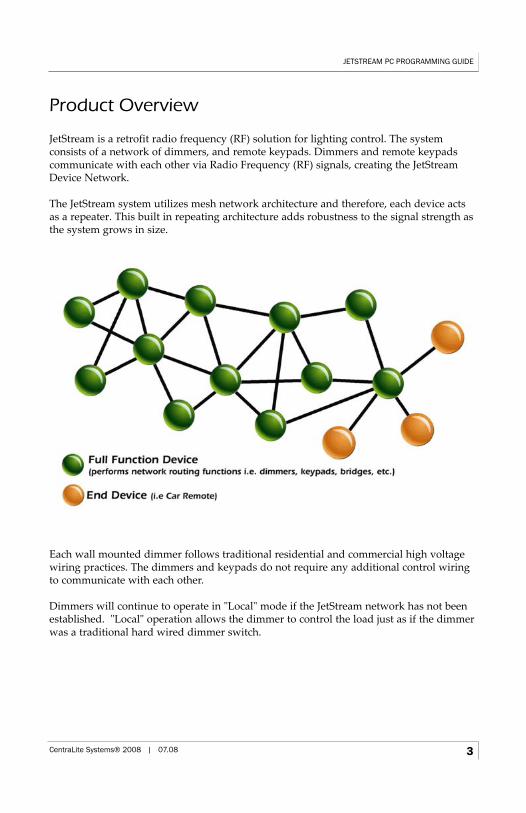
JetStream is a retrofit radio frequency (RF) solution for lighting control. The system consists of a network of dimmers, and remote keypads. Dimmers and remote keypadscommunicate with each other via Radio Frequency (RF) signals, creating the JetStreamDevice Network.
The JetStream system utilizes mesh network architecture and therefore, each device actsas a repeater. This built in repeating architecture adds robustness to the signal strength asthe system grows in size.
Each wall mounted dimmer follows traditional residential and commercial high voltagewiring practices. The dimmers and keypads do not require any additional control wiringto communicate with each other.
Dimmers will continue to operate in "Local" mode if the JetStream network has not beenestablished. "Local" operation allows the dimmer to control the load just as if the dimmerwas a traditional hard wired dimmer switch.
JETSTREAM PC PROGRAMMING GUIDE
CentraLite Systems® 2008 | 07.08 3
Components
DimmersOne (1) button neutral dimmers (800W) product number: 3385001-(W,I,LA,B)Three (3) button neutral dimmers (800W) product number: 3385003-(W,I,LA,B)Lamp module (300W) product number: 4255050
KeypadsOne (1) button keypad product number: 3385001-K-(W,I,LA,B)Three (3) button keypad product number: 3385003-K-(W,I,LA,B)Eight (8) button table top keypad product number: 4255008Car remote product number: 4255003
AccessoriesUSB Programming Bride product number: 3155002RS-232 Bridge with Astronomical Clock* product number: 3155000JetPak Automation System product number: 5454000-SIR/RS-232 Receiver product number: 4160003
*Available March 2008
Notes:
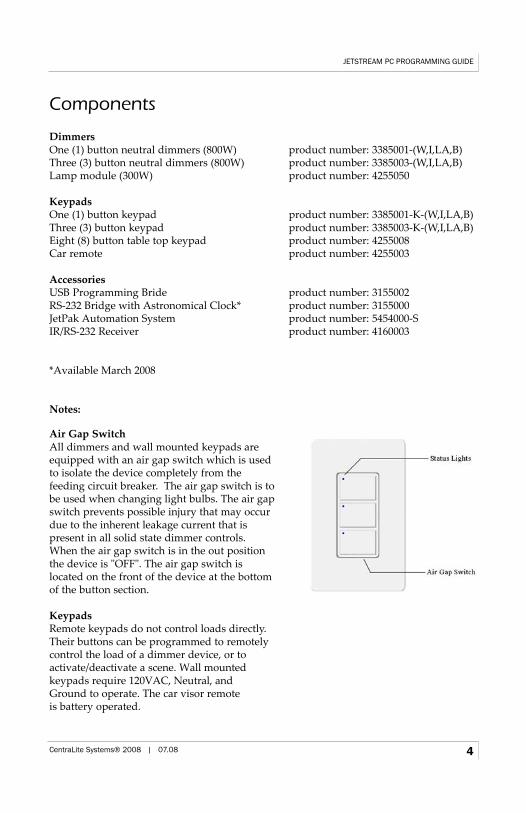
Air Gap SwitchAll dimmers and wall mounted keypads areequipped with an air gap switch which is usedto isolate the device completely from the feeding circuit breaker. The air gap switch is tobe used when changing light bulbs. The air gapswitch prevents possible injury that may occurdue to the inherent leakage current that is present in all solid state dimmer controls.When the air gap switch is in the out positionthe device is "OFF". The air gap switch is located on the front of the device at the bottomof the button section.
KeypadsRemote keypads do not control loads directly.Their buttons can be programmed to remotelycontrol the load of a dimmer device, or to activate/deactivate a scene. Wall mounted keypads require 120VAC, Neutral, and Ground to operate. The car visor remote is battery operated.
JETSTREAM PC PROGRAMMING GUIDE
CentraLite Systems® 2008 | 07.08 4
Detailed Description of Components
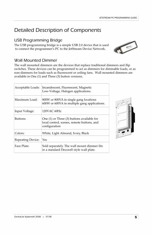
USB Programming BridgeThe USB programming bridge is a simple USB 2.0 device that is usedto connect the programmer's PC to the JetStream Device Network.
Wall Mounted DimmerThe wall mounted dimmers are the devices that replace traditional dimmers and flipswitches. These devices can be programmed to act as dimmers for dimmable loads, or asnon-dimmers for loads such as fluorescent or ceiling fans. Wall mounted dimmers areavailable in One (1) and Three (3) button versions.
Acceptable Loads: Incandescent, Fluorescent, Magnetic Low-Voltage, Halogen applications.
Maximum Load: 800W or 800VA in single gang locations600W or 600VA in multiple gang applications.
Input Voltage: 120VAC 60Hz
Buttons: One (1) or Three (3) buttons available for local control, scenes, remote buttons, and configuration
Colors: White, Light Almond, Ivory, Black
Repeating Device: Yes
Face Plate: Sold separately. The wall mount dimmer fits in a standard Decora® style wall plate.
JETSTREAM PC PROGRAMMING GUIDE
CentraLite Systems® 2008 | 07.08 5
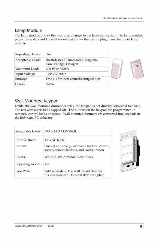
Lamp ModuleThe lamp module allows the user to add lamps to the JetStream system. The lamp moduleplugs into a standard US wall socket and allows the user to plug in one lamp per lampmodule.
Wall Mounted KeypadUnlike the wall mounted dimmer or relay, the keypad is not directly connected to a load.The red wire needs to be capped off. The buttons on the keypad are programmed toremotely control loads or scenes. Wall mounted dimmers are converted into keypads inthe JetStream PC software.
Acceptable Loads: NO LOAD CONTROL
Input Voltage: 120VAC 60Hz
Buttons: One (1) or Three (3) available for local control,scenes, remote buttons, and configuration
Colors: White, Light Almond, Ivory, Black
Repeating Device: Yes
Face Plate: Sold separately. The wall mount dimmer fits in a standard Decora® style wall plate.
JETSTREAM PC PROGRAMMING GUIDE
CentraLite Systems® 2008 | 07.08 6
Repeating Device: Yes
Acceptable Loads: Incandescent, Fluorescent, Magnetic Low-Voltage, Halogen
Maximum Load: 300 W or 300VAInput Voltage: 120VAC 60HzButtons: One (1) for local control/configurationColors: White
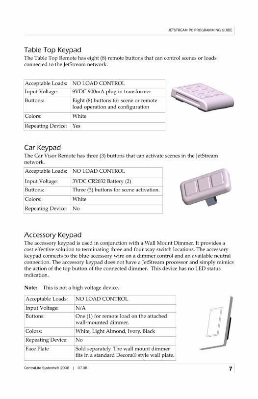
Table Top KeypadThe Table Top Remote has eight (8) remote buttons that can control scenes or loads connected to the JetStream network.
Car KeypadThe Car Visor Remote has three (3) buttons that can activate scenes in the JetStream network.
Accessory KeypadThe accessory keypad is used in conjunction with a Wall Mount Dimmer. It provides acost effective solution to terminating three and four way switch locations. The accessorykeypad connects to the blue accessory wire on a dimmer control and an available neutralconnection. The accessory keypad does not have a JetStream processor and simply mimicsthe action of the top button of the connected dimmer. This device has no LED status indication.
Note: This is not a high voltage device.
Acceptable Loads: NO LOAD CONTROLInput Voltage: 9VDC 900mA plug in transformer
Buttons: Eight (8) buttons for scene or remote load operation and configuration
Colors: White
Repeating Device: Yes
Acceptable Loads: NO LOAD CONTROL
Input Voltage: 3VDC CR2032 Battery (2)Buttons: Three (3) buttons for scene activation.
Colors: White
Repeating Device: No
JETSTREAM PC PROGRAMMING GUIDE
CentraLite Systems® 2008 | 07.08 7
Acceptable Loads: NO LOAD CONTROL
Input Voltage: N/AButtons: One (1) for remote load on the attached
wall-mounted dimmer.Colors: White, Light Almond, Ivory, BlackRepeating Device: No
Face Plate Sold separately. The wall mount dimmerfits in a standard Decora® style wall plate.
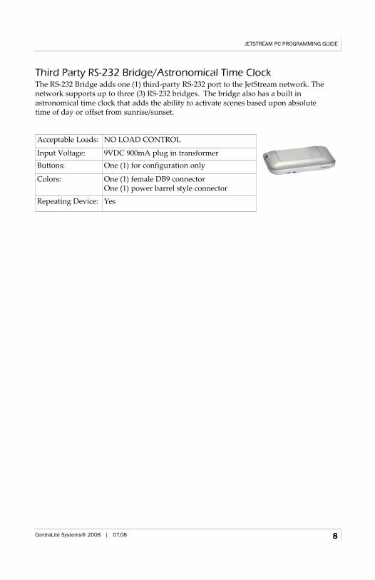
Third Party RS-232 Bridge/Astronomical Time ClockThe RS-232 Bridge adds one (1) third-party RS-232 port to the JetStream network. The network supports up to three (3) RS-232 bridges. The bridge also has a built in astronomical time clock that adds the ability to activate scenes based upon absolute time of day or offset from sunrise/sunset.
Acceptable Loads: NO LOAD CONTROL
Input Voltage: 9VDC 900mA plug in transformerButtons: One (1) for configuration only
Colors: One (1) female DB9 connectorOne (1) power barrel style connector
Repeating Device: Yes
JETSTREAM PC PROGRAMMING GUIDE
CentraLite Systems® 2008 | 07.08 8
Ordering Checklist
Neutral required in switch location: When retrofitting, you need to know the wiring scheme of the house. Most locations have a neutral present at the switch,some do not. JetStream will not work without a neutral wire in the switch location.Ask your electrician to make sure before ordering.
Gang configurations: Multi-gang locations require you to de-rate the dimmers to 600W, and also require multiple gang faceplates. When sharing a box with a low voltage device, a barrier is usually required for the electrical inspection in new construction.
Number of 3-ways in house: Each 3-way requires a one or three button keypad atthe remote end of the switch leg. Add one Wall Mount Keypad for each additional remote location.
Custom engraving: CentraLite offers custom button engraving. Visit www.centralite.com/engraving for more information.
Dimming Receptacles: Most codes and/or inspectors will not allow a dimmer ofany sort to control a receptacle, since non-lighting loads may be incompatible with adimmed output. You can use a wall mounted dimmer that is programmed to operate as a non-dimmer to control these receptacles.
Third Party Control: If the system requires third party control via RS-232, include the optional RS-232 Bridge.
Time Clock: If the system requires a time clock for timed events based on time of day or sunrise/sunset, you must include a RS-232 Bridge with Astronomical Time Clock.
JETSTREAM PC PROGRAMMING GUIDE
CentraLite Systems® 2008 | 07.08 9
Hardware Installation
The following steps are common to all wall mounted dimmer/keypad installations:
1. Identify all switches that will be replaced with JetStream devices.
2. Locate the circuit breaker or fuse controlling the switch that will be replaced and turnoff the circuit breaker or remove the fuse.
3. Remove the faceplate of the existing switch.
4. Use circuit tester or volt-meter to verify that power is off.
5. Remove the old switch and identify the following wires:120V feed from circuit breaker, Load (switch leg), Neutral, Ground,Travelers (3 and 4-way switches only)
6. Remove any dust or debris from the wall box.
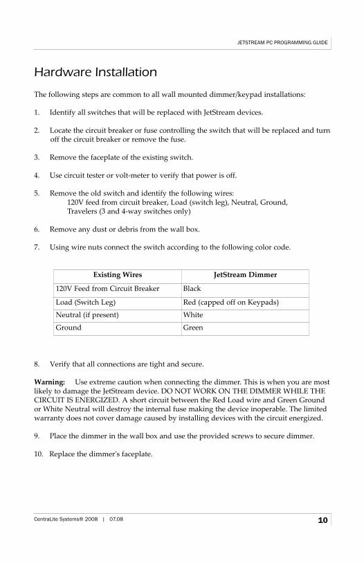
7. Using wire nuts connect the switch according to the following color code.
8. Verify that all connections are tight and secure.
Warning: Use extreme caution when connecting the dimmer. This is when you are mostlikely to damage the JetStream device. DO NOT WORK ON THE DIMMER WHILE THECIRCUIT IS ENERGIZED. A short circuit between the Red Load wire and Green Groundor White Neutral will destroy the internal fuse making the device inoperable. The limitedwarranty does not cover damage caused by installing devices with the circuit energized.
9. Place the dimmer in the wall box and use the provided screws to secure dimmer.
10. Replace the dimmer's faceplate.
JETSTREAM PC PROGRAMMING GUIDE
CentraLite Systems® 2008 | 07.08 10
Existing Wires JetStream Dimmer
120V Feed from Circuit Breaker Black
Load (Switch Leg) Red (capped off on Keypads)
Neutral (if present) White
Ground Green
11. Turn the circuit breaker on or replace the fuse. The device's top LED will be blinkingat a slow interval if the device is not part of a JetStream network. If the device is a dimmer with a load connected, the top button will operate the load as a dimmer unless the device is programmed as a non-dimmer. If the device is a keypad then thedevice's top LED will toggle states with every button press.
Note: When connecting to a 3 or 4 way circuit; connect the load to only one dimmer.Use remote keypads for the rest of the switch locations. Use the existing "traveler" wiresto provide a Neutral, Hot, and Ground connection at each of the remote keypad locations.
Warning: This product must be grounded in accordance to the NEC and Local requirements.
Warning: This product must be installed by a qualified licensed electrician.
Use the following diagrams to install the wall mount dimmers. Note that wire colors mayvary by installation and local codes.
JETSTREAM PC PROGRAMMING GUIDE
CentraLite Systems® 2008 | 07.08 11
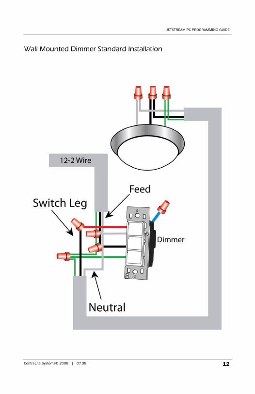
Wall Mounted Dimmer Standard Installation
JETSTREAM PC PROGRAMMING GUIDE
CentraLite Systems® 2008 | 07.08 12
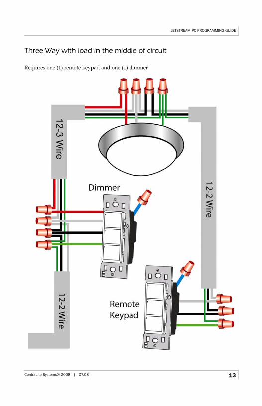
Three-Way with load in the middle of circuit
Requires one (1) remote keypad and one (1) dimmer
JETSTREAM PC PROGRAMMING GUIDE
CentraLite Systems® 2008 | 07.08 13
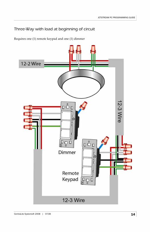
Three-Way with load at beginning of circuit
Requires one (1) remote keypad and one (1) dimmer
JETSTREAM PC PROGRAMMING GUIDE
CentraLite Systems® 2008 | 07.08 14
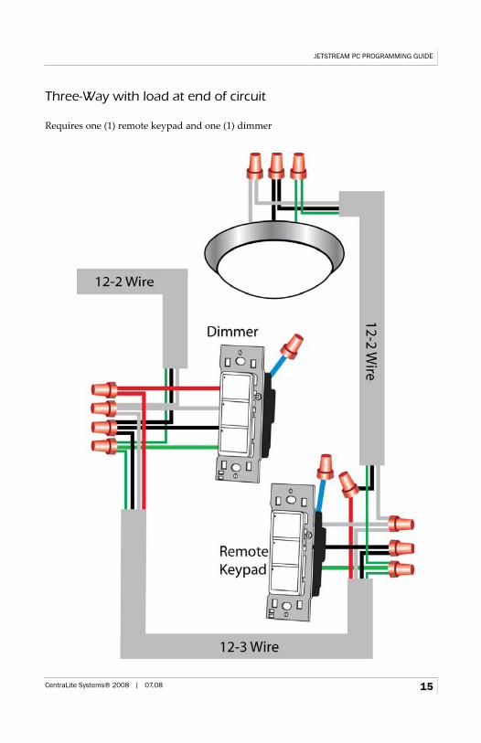
Three-Way with load at end of circuit
Requires one (1) remote keypad and one (1) dimmer
JETSTREAM PC PROGRAMMING GUIDE
CentraLite Systems® 2008 | 07.08 15
System Programming
Introduction to the JetStream NetworkThe JetStream Network is a Zigbee based mesh style network. This means the networkutilizes self-healing technology to ensure the best possible quality and robustness. Everydevice in the network that is always powered either by a plug in transformer or a hardwired connection acts as a network repeater. (Repeating devices must be within 40 feet ofanother repeating device) This means that as the system grows the network becomesstronger and gives more possible routing options in the event of an environmental changethat necessitates a network change.
The network resides on one 2.4GHz channel. The 2.4GHz spectrum is divided into sixteen(16) channels. The system automatically chooses the best available channel when formingthe network. However, in the event that the channel must be changed, the network allows manual configuration.
Note: The 2.4 GHz spectrum is populated by consumer electronics such as cordless telephones, Wi-Fi, microwave ovens, Bluetooth®, and other devices. It is important tonote that Wi-Fi is a high power network. Three (3) of the channels used in Wi-Fi overlapthirteen (13) of those used by JetStream. JetStream includes the functionality to determinewhat the least active channel is when forming the network. However, in a highly denseradio environment we recommend using a Spectrum analyzer tool to identify the cleanestchannel. Wi-Spy www.wi-spy.co.uk/ is a recommended open-source vendor for spectrum analyzers.
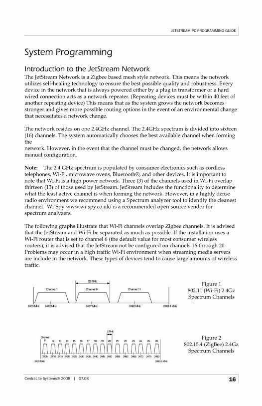
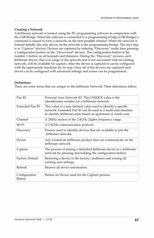
The following graphs illustrate that Wi-Fi channels overlap Zigbee channels. It is advisedthat the JetStream and Wi-Fi be separated as much as possible. If the installation uses a Wi-Fi router that is set to channel 6 (the default value for most consumer wirelessrouters), it is advised that the JetStream not be configured on channels 16 through 20.Problems may occur in a high traffic Wi-Fi environment when streaming media serversare include in the network. These types of devices tend to cause large amounts of wirelesstraffic.
JETSTREAM PC PROGRAMMING GUIDE
CentraLite Systems® 2008 | 07.08 16
Figure 1802.11 (Wi-Fi) 2.4Gz Spectrum Channels
Figure 2802.15.4 (ZigBee) 2.4Gz
Spectrum Channels
Creating a NetworkA JetStream network is formed using the PC programming software in conjunction withthe USB Bridge. When the software is connected to a programming bridge (USB Bridge) acommand is issued to form a network on the best possible channel. When the network isformed initially the only device on the network is the programming bridge. The next stepis to "Capture" devices. Devices are captured by entering "Discovery" mode then pressinga configuration button on the "Discovered" devices. The configuration button is the number 1 button on all keypads and dimmers. During the "Discovery" process, eachJetStream device, that is in range of the network and is not associated with an existingnetwork, will be available for capture. After the device is captured it can be configuredwith the appropriate functions for its type. Once all of the devices are captured eachdevice can be configured with advanced settings and scenes can be programmed.
DefinitionsThere are some terms that are unique to the JetStream Network. Their definitions follow.
JETSTREAM PC PROGRAMMING GUIDE
CentraLite Systems® 2008 | 07.08 17
Pan ID Personal Area Network ID. This UNIQUE value is the identification number for a JetStream network.
Extended Pan ID This value is a user defined value used to identify a specific network. Extended Pan ID can be used in a multi-unit situation to identify JetStream units based on apartment or condo unit.
Channel A 2MHz section of the 2.4GHz Zigbee frequency range.
Wi-Fi A 2.4GHz communication protocol.
Discovery Process used to identify devices that are available to join theJetStream network.
Device Any CentraLite JetStream product that can communicate on theJetStream network
Capture The process of joining a defaulted JetStream device to a JetStreamnetwork by pressing and holding the configuration button.
Factory Default Restoring a device to the factory conditions and erasing all existing user settings.
Refresh Receive all device information.
ConfigurationButton
Button on Device used for the Capture process.
Software InstallationThe JetStream software installation is very user intuitive. Follow the next steps for quickinstallation of the software.
• Supported Microsoft Windows Versions:• Windows XP Home/Professional• Windows Vista (any version)
Note Regarding Microsoft Vista™: For computers that are running Windows Vista it isstrongly advised that the program is installed by a user with Administrative rights.
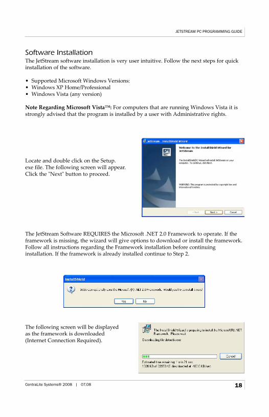
Locate and double click on the Setup.exe file. The following screen will appear. Click the "Next" button to proceed.
The JetStream Software REQUIRES the Microsoft .NET 2.0 Framework to operate. If theframework is missing, the wizard will give options to download or install the framework.Follow all instructions regarding the Framework installation before continuing installation. If the framework is already installed continue to Step 2.
The following screen will be displayed as the framework is downloaded (Internet Connection Required).
JETSTREAM PC PROGRAMMING GUIDE
CentraLite Systems® 2008 | 07.08 18
When the framework download is complete click "Run" to begin installation.
Click "Next" on the following screen to begin the framework installation.
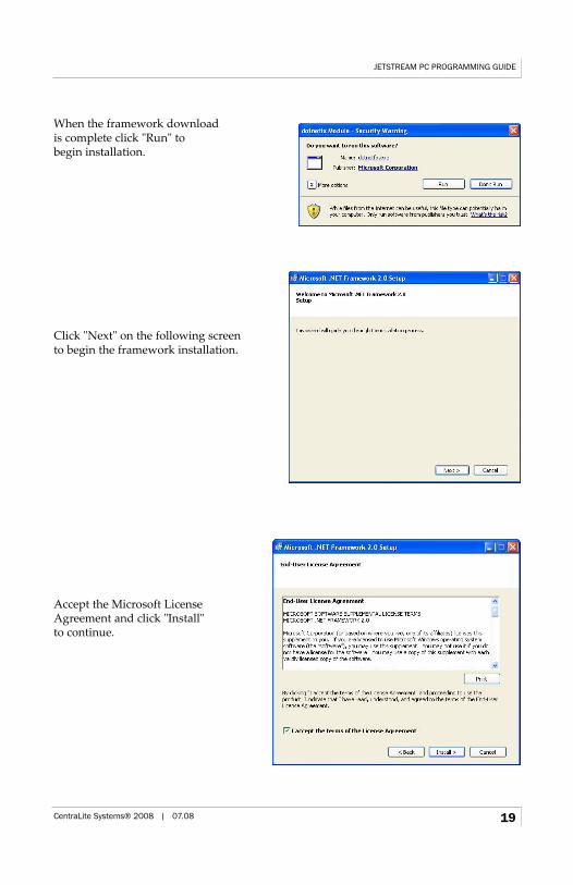
Accept the Microsoft License Agreement and click "Install" to continue.
JETSTREAM PC PROGRAMMING GUIDE
CentraLite Systems® 2008 | 07.08 19
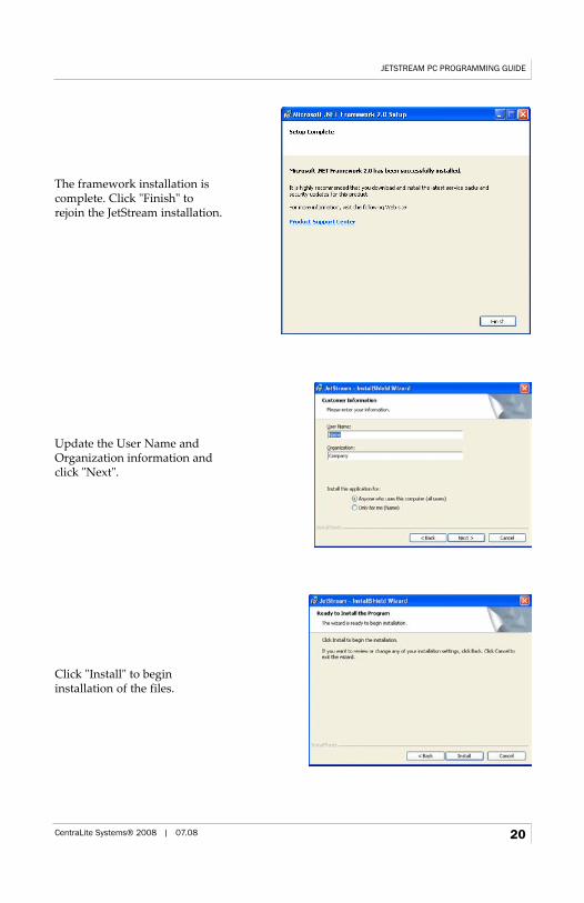
The framework installation is complete. Click "Finish" to rejoin the JetStream installation.
Update the User Name and Organization information and click "Next".
Click "Install" to begin installation of the files.
JETSTREAM PC PROGRAMMING GUIDE
CentraLite Systems® 2008 | 07.08 20
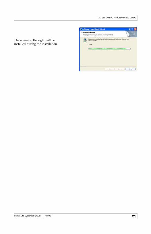
The screen to the right will be installed during the installation.
JETSTREAM PC PROGRAMMING GUIDE
CentraLite Systems® 2008 | 07.08 21
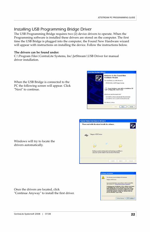
Installing USB Programming Bridge DriverThe USB Programming Bridge requires two (2) device drivers to operate. When theProgramming software is installed these drivers are stored on the computer. The first time the USB Bridge is plugged into the computer, the Found New Hardware wizard will appear with instructions on installing the device. Follow the instructions below.
The drivers can be found under:C:\Program Files\CentraLite Systems, Inc\JetStream\USB Driver for manual driver installation.
When the USB Bridge is connected to the PC the following screen will appear. Click "Next" to continue.
Windows will try to locate the drivers automatically.
Once the drivers are located, click "Continue Anyway" to install the first driver.
JETSTREAM PC PROGRAMMING GUIDE
CentraLite Systems® 2008 | 07.08 22
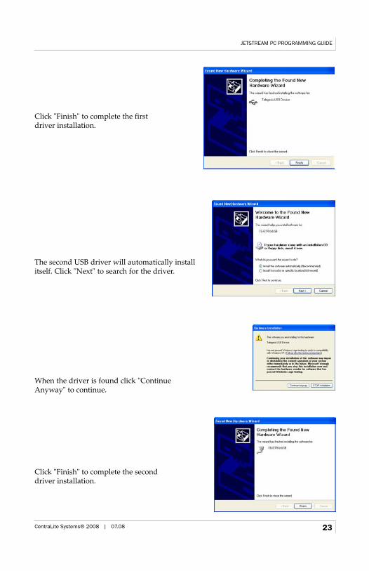
Click "Finish" to complete the first driver installation.
The second USB driver will automatically installitself. Click "Next" to search for the driver.
When the driver is found click "Continue Anyway" to continue.
Click "Finish" to complete the second driver installation.
JETSTREAM PC PROGRAMMING GUIDE
CentraLite Systems® 2008 | 07.08 23
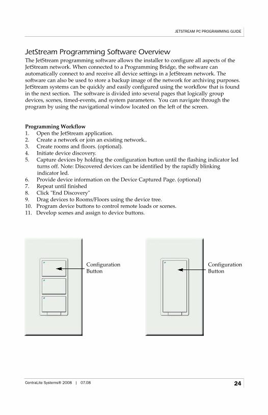
JetStream Programming Software OverviewThe JetStream programming software allows the installer to configure all aspects of theJetStream network. When connected to a Programming Bridge, the software can automatically connect to and receive all device settings in a JetStream network. The software can also be used to store a backup image of the network for archiving purposes.JetStream systems can be quickly and easily configured using the workflow that is foundin the next section. The software is divided into several pages that logically groupdevices, scenes, timed-events, and system parameters. You can navigate through the program by using the navigational window located on the left of the screen.
Programming Workflow1. Open the JetStream application. 2. Create a network or join an existing network.. 3. Create rooms and floors. (optional).4. Initiate device discovery. 5. Capture devices by holding the configuration button until the flashing indicator led
turns off. Note: Discovered devices can be identified by the rapidly blinking indicator led.
6. Provide device information on the Device Captured Page. (optional)7. Repeat until finished8. Click "End Discovery"9. Drag devices to Rooms/Floors using the device tree.10. Program device buttons to control remote loads or scenes. 11. Develop scenes and assign to device buttons.
JETSTREAM PC PROGRAMMING GUIDE
CentraLite Systems® 2008 | 07.08 24
Configuration Button
Configuration Button
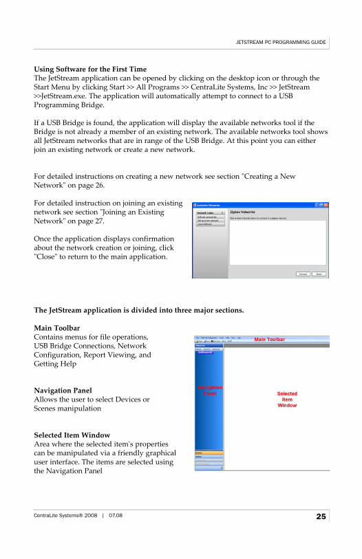
Using Software for the First TimeThe JetStream application can be opened by clicking on the desktop icon or through theStart Menu by clicking Start >> All Programs >> CentraLite Systems, Inc >> JetStream>>JetStream.exe. The application will automatically attempt to connect to a USBProgramming Bridge.
If a USB Bridge is found, the application will display the available networks tool if theBridge is not already a member of an existing network. The available networks tool showsall JetStream networks that are in range of the USB Bridge. At this point you can eitherjoin an existing network or create a new network.
For detailed instructions on creating a new network see section "Creating a NewNetwork" on page 26.
For detailed instruction on joining an existingnetwork see section "Joining an ExistingNetwork" on page 27.
Once the application displays confirmationabout the network creation or joining, click"Close" to return to the main application.
The JetStream application is divided into three major sections.
Main ToolbarContains menus for file operations, USB Bridge Connections, NetworkConfiguration, Report Viewing, andGetting Help
Navigation PanelAllows the user to select Devices or Scenes manipulation
Selected Item WindowArea where the selected item's properties can be manipulated via a friendly graphical user interface. The items are selected using the Navigation Panel
JETSTREAM PC PROGRAMMING GUIDE
CentraLite Systems® 2008 | 07.08 25
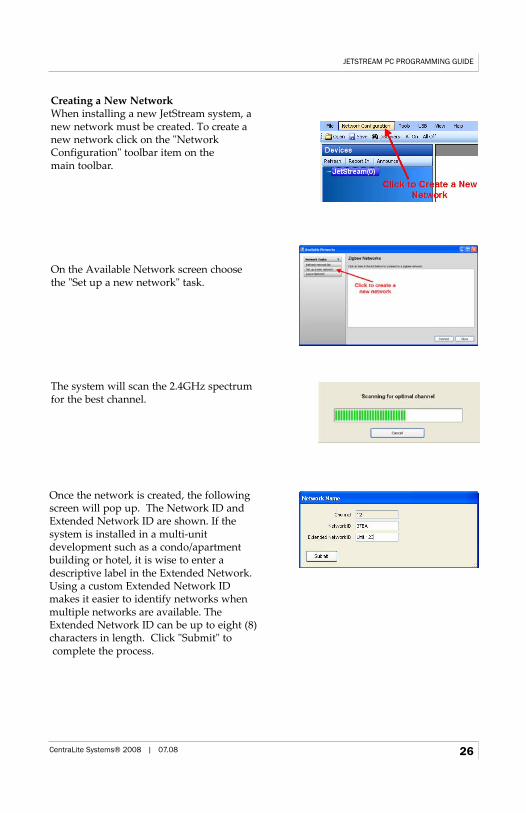
Creating a New NetworkWhen installing a new JetStream system, a new network must be created. To create a new network click on the "Network Configuration" toolbar item on the main toolbar.
On the Available Network screen choose the "Set up a new network" task.
The system will scan the 2.4GHz spectrum for the best channel.
JETSTREAM PC PROGRAMMING GUIDE
CentraLite Systems® 2008 | 07.08 26
Once the network is created, the followingscreen will pop up. The Network ID andExtended Network ID are shown. If the system is installed in a multi-unit development such as a condo/apartmentbuilding or hotel, it is wise to enter adescriptive label in the Extended Network.Using a custom Extended Network IDmakes it easier to identify networks whenmultiple networks are available. TheExtended Network ID can be up to eight (8)characters in length. Click "Submit" tocomplete the process.
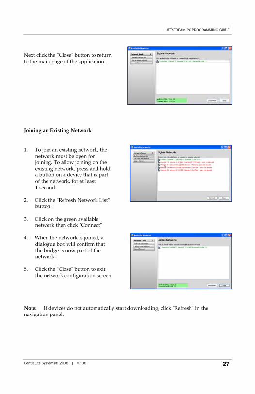
Next click the "Close" button to return to the main page of the application.
Joining an Existing Network
Note: If devices do not automatically start downloading, click "Refresh" in the navigation panel.
JETSTREAM PC PROGRAMMING GUIDE
CentraLite Systems® 2008 | 07.08 27
1. To join an existing network, thenetwork must be open for joining. To allow joining on theexisting network, press and hold a button on a device that is partof the network, for at least 1 second.
2. Click the "Refresh Network List"button.
3. Click on the green available network then click "Connect"
4. When the network is joined, a dialogue box will confirm thatthe bridge is now part of the network.
5. Click the "Close" button to exitthe network configuration screen.
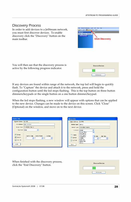
Discovery ProcessIn order to add devices to a JetStream network, you must first discover devices. To enable discovery click the "Discovery" button on the main toolbar.
You will then see that the discovery process is active by the following progress indicator.
If any devices are found within range of the network, the top led will begin to quicklyflash. To "Capture" the device and attach it to the network, press and hold the configuration button until the led stops flashing. This is the top button on three buttondimmers/keypads or the single button on a one button dimmer/keypad.
When the led stops flashing, a new window will appear with options that can be appliedto the new device. Changes can be made to the device on this screen. Click "Close"(Optional) on the window, and move on to the next device.
When finished with the discovery process, click the "End Discovery" button.
JETSTREAM PC PROGRAMMING GUIDE
CentraLite Systems® 2008 | 07.08 28
Device Screen
Organization with Rooms and Floors
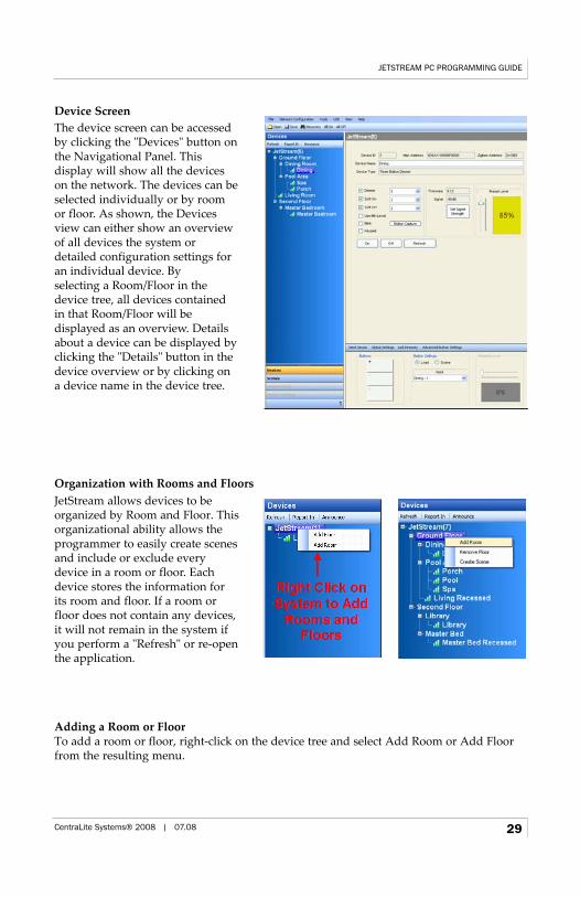
Adding a Room or FloorTo add a room or floor, right-click on the device tree and select Add Room or Add Floorfrom the resulting menu.
JETSTREAM PC PROGRAMMING GUIDE
CentraLite Systems® 2008 | 07.08 29
The device screen can be accessedby clicking the "Devices" button onthe Navigational Panel. This display will show all the deviceson the network. The devices can beselected individually or by roomor floor. As shown, the Devicesview can either show an overviewof all devices the system ordetailed configuration settings foran individual device. By selecting a Room/Floor in thedevice tree, all devices containedin that Room/Floor will be displayed as an overview. Detailsabout a device can be displayed byclicking the "Details" button in thedevice overview or by clicking ona device name in the device tree.
JetStream allows devices to beorganized by Room and Floor. Thisorganizational ability allows theprogrammer to easily create scenesand include or exclude everydevice in a room or floor. Eachdevice stores the information forits room and floor. If a room orfloor does not contain any devices,it will not remain in the system ifyou perform a "Refresh" or re-openthe application.
Removing a Room or FloorRooms and floors can be deleted by right clicking on the selected object and choosing"Remove Floor" or "Remove Room". This action only deletes the room or floor and doesnot delete the devices included in the room or floor.
Note: Room and Floor information is stored in each device that is a member of thatroom or floor. If a Room or Floor does not have any members, it will not persist in theDevice Tree if the Refresh button is pressed or if the program is restarted.
Creating a Room or Floor Scene
JETSTREAM PC PROGRAMMING GUIDE
CentraLite Systems® 2008 | 07.08 30
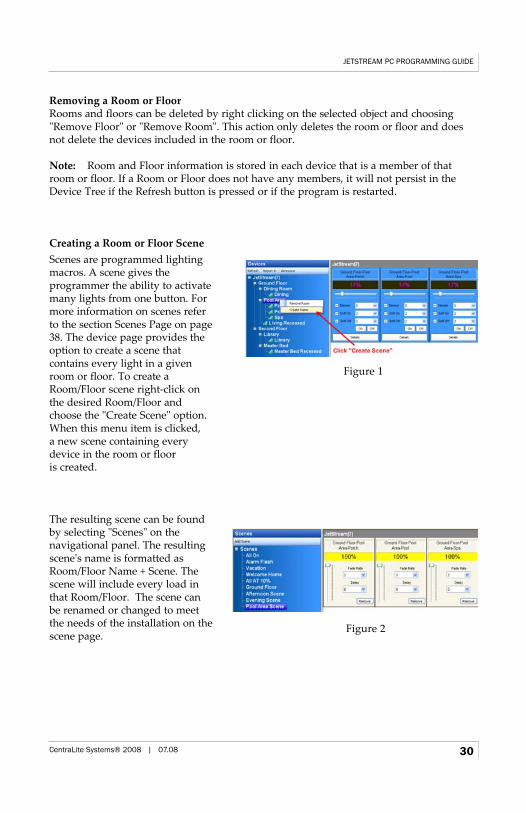
The resulting scene can be foundby selecting "Scenes" on the navigational panel. The resultingscene's name is formatted asRoom/Floor Name + Scene. Thescene will include every load inthat Room/Floor. The scene canbe renamed or changed to meetthe needs of the installation on thescene page.
Figure 1
Figure 2
Scenes are programmed lighting macros. A scene gives the programmer the ability to activatemany lights from one button. Formore information on scenes referto the section Scenes Page on page38. The device page provides theoption to create a scene that contains every light in a givenroom or floor. To create aRoom/Floor scene right-click onthe desired Room/Floor andchoose the "Create Scene" option.When this menu item is clicked, a new scene containing everydevice in the room or floor is created.
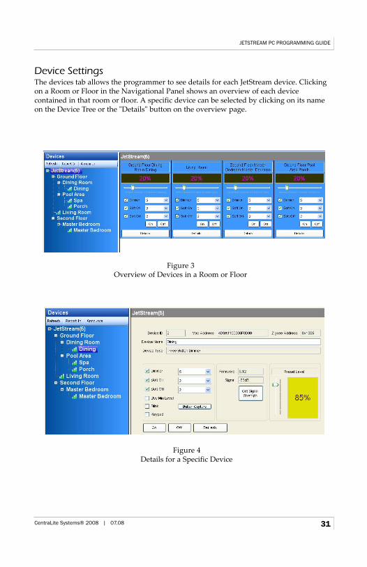
Device SettingsThe devices tab allows the programmer to see details for each JetStream device. Clickingon a Room or Floor in the Navigational Panel shows an overview of each device contained in that room or floor. A specific device can be selected by clicking on its nameon the Device Tree or the "Details" button on the overview page.
JETSTREAM PC PROGRAMMING GUIDE
CentraLite Systems® 2008 | 07.08 31
Figure 3Overview of Devices in a Room or Floor
Figure 4Details for a Specific Device
Dimmers and Keypads
Load Settings
JETSTREAM PC PROGRAMMING GUIDE
CentraLite Systems® 2008 | 07.08 32
Settings Functions
Device ID The ID used to control this device using the JetStream Third PartyProtocol
Mac Address The 64 bit unique address assigned to the device from the factory. This is NOT a TCP/IP Mac Address.
Zigbee Address The 16 bit address assigned to the device during the discover process.
Device Name The name of the device. This value can be updated at any time. It is recommended to name the device by location then function. The nameis limited to 32 characters.
Device Type The type of device currently selected.
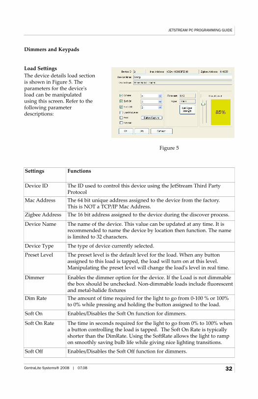
Preset Level The preset level is the default level for the load. When any buttonassigned to this load is tapped, the load will turn on at this level.Manipulating the preset level will change the load's level in real time.
Dimmer Enables the dimmer option for the device. If the Load is not dimmablethe box should be unchecked. Non-dimmable loads include fluorescentand metal-halide fixtures
Dim Rate The amount of time required for the light to go from 0-100 % or 100% to 0% while pressing and holding the button assigned to the load.
Soft On Enables/Disables the Soft On function for dimmers.
Soft On Rate The time in seconds required for the light to go from 0% to 100% whena button controlling the load is tapped. The Soft On Rate is typicallyshorter than the DimRate. Using the SoftRate allows the light to rampon smoothly saving bulb life while giving nice lighting transitions.
Soft Off Enables/Disables the Soft Off function for dimmers.
The device details load sectionis shown in Figure 5. Theparameters for the device'sload can be manipulatedusing this screen. Refer to thefollowing parameter descriptions:
Figure 5
JETSTREAM PC PROGRAMMING GUIDE
CentraLite Systems® 2008 | 07.08 33
Settings Functions
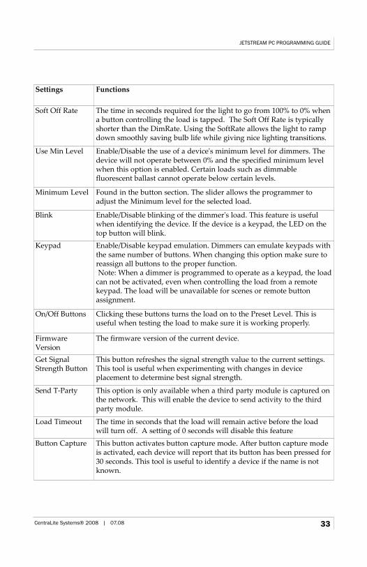
Soft Off Rate The time in seconds required for the light to go from 100% to 0% whena button controlling the load is tapped. The Soft Off Rate is typicallyshorter than the DimRate. Using the SoftRate allows the light to rampdown smoothly saving bulb life while giving nice lighting transitions.
Use Min Level Enable/Disable the use of a device's minimum level for dimmers. Thedevice will not operate between 0% and the specified minimum levelwhen this option is enabled. Certain loads such as dimmable fluorescent ballast cannot operate below certain levels.
Minimum Level Found in the button section. The slider allows the programmer toadjust the Minimum level for the selected load.
Blink Enable/Disable blinking of the dimmer's load. This feature is usefulwhen identifying the device. If the device is a keypad, the LED on thetop button will blink.
Keypad Enable/Disable keypad emulation. Dimmers can emulate keypads withthe same number of buttons. When changing this option make sure toreassign all buttons to the proper function.Note: When a dimmer is programmed to operate as a keypad, the load
can not be activated, even when controlling the load from a remote keypad. The load will be unavailable for scenes or remote buttonassignment.
On/Off Buttons Clicking these buttons turns the load on to the Preset Level. This is useful when testing the load to make sure it is working properly.
FirmwareVersion
The firmware version of the current device.
Get SignalStrength Button
This button refreshes the signal strength value to the current settings.This tool is useful when experimenting with changes in device placement to determine best signal strength.
Send T-Party This option is only available when a third party module is captured onthe network. This will enable the device to send activity to the thirdparty module.
Load Timeout The time in seconds that the load will remain active before the loadwill turn off. A setting of 0 seconds will disable this feature
Button Capture This button activates button capture mode. After button capture modeis activated, each device will report that its button has been pressed for30 seconds. This tool is useful to identify a device if the name is notknown.
Button Settings
Hint: You can right click on a button and the device will perform the action just as ifyou pressed the actual button.
Button Controlling a Scene
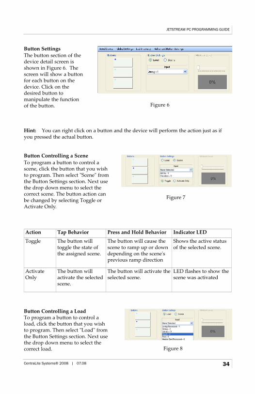
Button Controlling a LoadTo program a button to control a load, click the button that you wish to program. Then select "Load" from the Button Settings section. Next use the drop down menu to select the correct load.
JETSTREAM PC PROGRAMMING GUIDE
CentraLite Systems® 2008 | 07.08 34
Action Tap Behavior Press and Hold Behavior Indicator LED
Toggle The button will toggle the state ofthe assigned scene.
The button will cause thescene to ramp up or downdepending on the scene'sprevious ramp direction
Shows the active statusof the selected scene.
ActivateOnly
The button will activate the selectedscene.
The button will activate theselected scene.
LED flashes to show thescene was activated
The button section of thedevice detail screen isshown in Figure 6. Thescreen will show a buttonfor each button on thedevice. Click on thedesired button to manipulate the function of the button.
To program a button to control ascene, click the button that you wishto program. Then select "Scene" fromthe Button Settings section. Next usethe drop down menu to select thecorrect scene. The button action canbe changed by selecting Toggle orActivate Only.
Figure 6
Figure 7
Figure 8
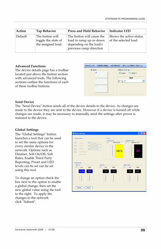
Advanced FunctionsThe device details page has a toolbar located just above the button section with advanced tools. The following sections outline the functions of each of these toolbar buttons.
Send DeviceThe "Send Device" button sends all of the device details to the device. As changes aremade to the device they are sent to the device. However if a device is turned off whilechanges are made, it may be necessary to manually send the settings after power isrestored to the device.
Global Settings
JETSTREAM PC PROGRAMMING GUIDE
CentraLite Systems® 2008 | 07.08 35
Action Tap Behavior Press and Hold Behavior Indicator LEDDefault The button will
toggle the state ofthe assigned load.
The button will cause theload to ramp up or downdepending on the load'sprevious ramp direction
Shows the active statusof the selected load.
The "Global Settings" buttonlaunches a tool that can be usedto set the same options forevery similar device in the network. Options such asDimmer, Soft On/Off, SoftRates, Enable Third PartyReporting, Preset and LED levels can be set can be setusing this tool.
To change an option check thebox next to the option to enablea global change, then set thenew global value using the toolto the right. To apply thechanges to the network click "Submit".
LED Intensity
Advanced Button Settings
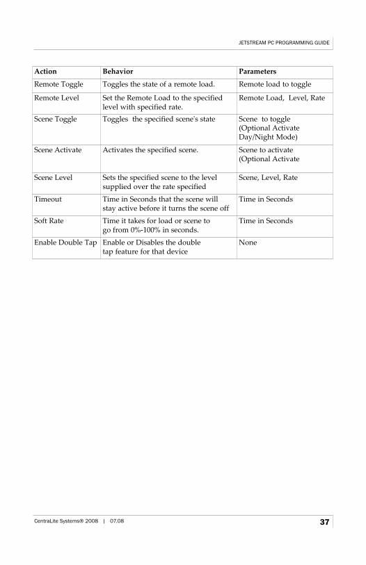
Day/Night Mode can be activated through a Scene. In order to setup this feature, set thebutton tap action to "Scene Activate" and check either the "Act Night" for night mode or"Act Day" for day mode. When this button is tapped, the corresponding mode will beactivated.
While in the Advanced Button Setting page, double and single taps can be tested. Whilethe "Tap" function is selected, right click on the desired button to simulate a button tap.To test the "Double Tap" feature, change the function to double tap and right click on thedesired button.
JETSTREAM PC PROGRAMMING GUIDE
CentraLite Systems® 2008 | 07.08 36
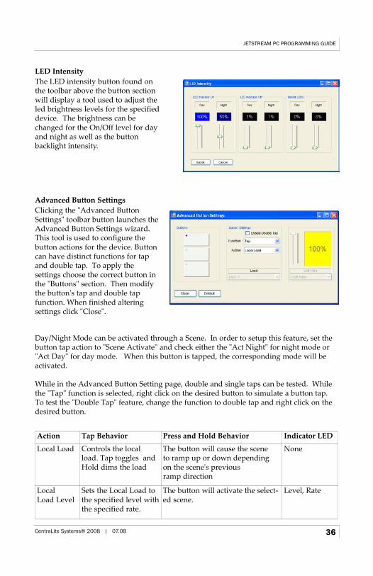
The LED intensity button found onthe toolbar above the button sectionwill display a tool used to adjust theled brightness levels for the specifieddevice. The brightness can bechanged for the On/Off level for dayand night as well as the button backlight intensity.
Clicking the "Advanced ButtonSettings" toolbar button launches theAdvanced Button Settings wizard.This tool is used to configure thebutton actions for the device. Buttoncan have distinct functions for tapand double tap. To apply the settings choose the correct button inthe "Buttons" section. Then modifythe button's tap and double tap function. When finished altering settings click "Close".
Action Tap Behavior Press and Hold Behavior Indicator LED
Local Load Controls the localload. Tap toggles andHold dims the load
The button will cause the scene to ramp up or down depending on the scene's previous ramp direction
None
Local Load Level
Sets the Local Load tothe specified level withthe specified rate.
The button will activate the select-ed scene.
Level, Rate
JETSTREAM PC PROGRAMMING GUIDE
CentraLite Systems® 2008 | 07.08 37
Action Behavior Parameters
Remote Toggle Toggles the state of a remote load. Remote load to toggle
Remote Level Set the Remote Load to the specifiedlevel with specified rate.
Remote Load, Level, Rate
Scene Toggle Toggles the specified scene's state Scene to toggle(Optional Activate Day/Night Mode)
Scene Activate Activates the specified scene. Scene to activate(Optional Activate
Scene Level Sets the specified scene to the level supplied over the rate specified
Scene, Level, Rate
Timeout Time in Seconds that the scene will stay active before it turns the scene off
Time in Seconds
Soft Rate Time it takes for load or scene to go from 0%-100% in seconds.
Time in Seconds
Enable Double Tap Enable or Disables the double tap feature for that device
None
Scenes Page
Creating a Scene
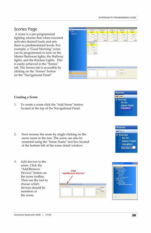
1. To create a scene click the "Add Scene" button located at the top of the Navigational Panel.
2. Next rename the scene by single clicking on the scene name in the tree. The scene can also be renamed using the "Scene Name" text box located at the bottom left of the scene detail window.
JETSTREAM PC PROGRAMMING GUIDE
CentraLite Systems® 2008 | 07.08 38
A scene is a pre-programmed lighting scheme that when executed activates desired loads and setsthem to predetermined levels. Forexample, a "Good Morning" scenecan be programmed to turn on theMaster Bedroom lights, the Hallwaylights, and the Kitchen Lights. Thisis easily achieved in the "Scenes" tab. The Scenes tab is accessible by clicking on the "Scenes" button on the "Navigational Panel"
3. Add devices to the scene. Click the"Add/Remove Devices" button onthe scene toolbar. Then use the tool tochoose which devices should bemembers of the scene.
Tip: Holding CTRL while changing a value applies the value to all devices.
5. Test the scene behavior by clicking the "Activate" and "Deactivate" buttons.
6. Assign the scene to device buttons using the "Device" page. All assigned buttons and timed events will be shown in the boxes just under the scene toolbar.
ASCII SceneAll scenes have the ability to send out a twenty (20) character string on the activation of ascene and a different ASCII string on the deactivation of a scene. In order for this optionto appear, a RS232 Bridge must be present in the current JetStream network. The ASCIIbutton will appear on the scene toolbar.
Copy SceneScenes can be copied. This saves programming time when severalscenes will have similar behavior. To copy a scene, right click on thescene to copy and choose the "Copy Scene" option. A new scene will be created with the name "xxx Copy" where xxx is the previous scene name.
Remove a SceneTo delete a scene remove all devices from the scene using the Add/Remove Devices tool.When the system's network data is refreshed the scene will not return because there areno devices with information regarding that scene.
JETSTREAM PC PROGRAMMING GUIDE
CentraLite Systems® 2008 | 07.08 39
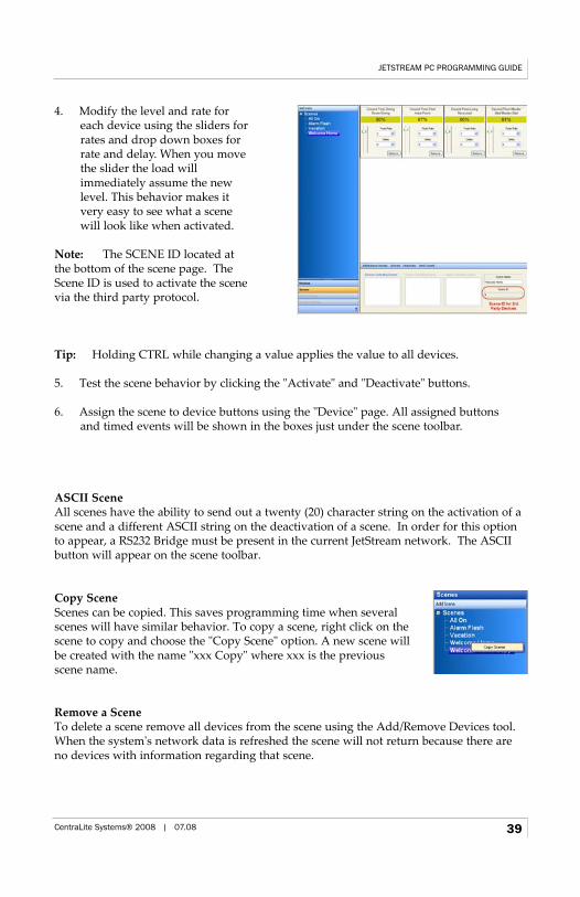
4. Modify the level and rate for each device using the sliders forrates and drop down boxes for rate and delay. When you move the slider the load will immediately assume the new level. This behavior makes it very easy to see what a scene will look like when activated.
Note: The SCENE ID located atthe bottom of the scene page. TheScene ID is used to activate the scenevia the third party protocol.

One and Three Button Dimmers
Defaulting One and Three Button DimmersFollow the list of instructions to reset a device to the factory presets.
1. Pull out the air gap switch or turn off the breaker supplying power to the device.
2. Press and hold the top button on a three (3) button device or the single button of a 1 button device.
3. Restore power to the device by pressing in the air gap switch or turning on thepower supply breaker while still holding the button.
4. When the power is restored the top indicator light will begin to flash, keep the buttonpressed until the indicator light turns off. This usually takes around four (4) seconds.
5. The device is now restored to factory preset values and is now available to join aJetStream network.
JETSTREAM PC PROGRAMMING GUIDE
CentraLite Systems® 2008 | 07.08 40
Third Party Command Structure
Bringing the RS-232 Bridge into the Network
DiscoveryOut of the box, the RS-232 Bridge is not part of any JetStream Networks. The first step inbringing the device into the network is discovery. For discovery, plug in your USB Bridgeto your PC and begin the JetStream programming software. Next, find a good spot for theRS-232 Bridge to live. Preferably it needs to reside in an open area at within 40' of a nearby device. After plugging in the RS-232 Bridge, the “Discovery” LED will slowlyblink. Once the software has read all the current devices, click on the Discovery button atthe top of the page. The system will now go into "Discovery" mode. Once the RS-232Bridge has been discovered, its discovery LED will begin flashing repidly and is ready tobe captured.
CaptureThe Capture process will enroll the RS-232 Bridge into your specific JetStream Network.To accomplish this, tap the button on the front right side of the device after the LED is fastblinking. Once captured, the LED on the right now becomes an activity LED. You willsee it flicker every once and a while. This is a normal behavior.
In the software, a dialog box will appear in which, you can name your device and place itin its correct room/floor location. Click "Close" and the device will now show up in thedevice list on the left-hand side of the page.
JETSTREAM PC PROGRAMMING GUIDE
CentraLite Systems® 2008 | 07.08 41
Configuring the RS-232 Bridge for Your Area
Since the RS-232 Bridge contains an astronomical clock that tracks sunrise and sunset, thelocation (latitude/longitude) of the device must be provided. For US residence, a zip codecan be provided and the location will automatically be determined. For non-US customers, latitude and longitude must be known prior to setting up events.
Setting the LocationIn order to setup timed events, the location of the RS-232 Bridge must be programmed. Inorder to do this, please follow these steps.
1. Select the RS-232 Bridge in the Device List on the left hand side of the JetStream Software.
2. Click on the "Location" button in the middle of the page.3. For US residents simply enter your zip code and the latitude/longitude will be filled
in automatically. For non-US customers, leave the Zip code field blank and manuallyenter your latitude/longitude and time zone.
4. By default, Daylight Savings is in used. If you are in a city that does not useDaylight Savings, uncheck the "use Daylight Savings" box
5. When all is correct, click the "Submit" button.
Setting the Baud RateBy default the RS-232 Bridge's baud rate is set to 19200. If you need to change this pleasefollow these steps.
1. Select the RS-232 Bridge in the Device List on the left hand side of the JetStream Software.
2. Click on the "Settings" button in the middle of the page.3. Click on the Drop down arrow next to Baud Rate and select your desired baud rate.4. When all is correct, click the "Submit" button.
Setting Daylight Savings ParametersBy default the RS-232 Bridge's DST is set to begin on the 2nd Sunday of March and endon the 1st Sunday of November. If you need to change this please follow these steps.
1. Select the RS-232 Bridge in the Device List on the left hand side of the JetStream Software.
2. Click on the "Settings" button in the middle of the page.3. Click on the Drop down arrow next to Begin Sunday and select your desired Sunday.4. Click on the Drop down arrow next to Begin Month and select your desired Month.5. Click on the Drop down arrow next to End Sunday and select your desired Sunday.6. Click on the Drop down arrow next to End Month and select your desired Month.7. When all is correct, click the "Submit" button.
JETSTREAM PC PROGRAMMING GUIDE
CentraLite Systems® 2008 | 07.08 42
Setting the Date and TimeBefore any Events can occur, the correct Date and Time need to be set on the RS-232Bridge. To do this, please follow these steps:
1. Select the RS-232 Bridge in the Device List on the left hand side of the JetStream Software.
2. If your PC clock is correct, click on the “Clock-PC Sync” button. This will send thedate and time your PC thinks it is to the RS-232 Bridge.
3. You can also set it manually by entering in the correct time and date and clicking the“Set Time” button. To check this, click the “Get Time” Button and you will see thetime that is currently in the RS-232 Bridge.
Hint: Pay attention to the AM/PM values. It is important that this is correct. Or else allevents will be 12 hours off.
JETSTREAM PC PROGRAMMING GUIDE
CentraLite Systems® 2008 | 07.08 43
Setting up a Timed Event
Each RS-232 Bridge allows for 50 timed events. All events will be displayed under the RS-232 Bridge in the device list in the software. To view these events, click on the “plus”sign next to the RS-232 Bridge on your device list. A timed event can either activate or deactivate a programmed scene on your JetStream system at an absolute time (9:00am) or a relative time to sunrise/sunset (10 minutes before/after sunrise/sunset).
Absolute Timed EventA timed event can be set up to occur at a specified time of day. This is called an AbsoluteTimed Event. To setup an Absolute Timed Event please follow these steps:
1. Select the RS-232 Bridge in the Device List on the left hand side of the JetStream software.
2. Expand the events by clicking on the “plus” sign next to your RS-232 Bridge.3. Click on the event you wish to modify.4. Name the Event (10 characters max).5. Check the active box to set the event as being used.6. Select the scene you wish to control from the drop down list. If you have not created
the scene yet, please see the programming manual to create a scene.7. Select whether you want the scene to be activated or deactivated. For example. You
might want your outside lights scene to be activated at 7:00pm as an event and thenfor another event, you can have your outside lights scene be deactivated at 11:00pm.
8. Click the “Scheduling” Tab.9. Select the Hour and Minute you would like this event to occur.10. Select all Days of the week and Months of the year you would like this event to occur.11. When all is correct, click the “Submit” button.
Relative Timed Event (Sunrise/Sunset)A timed event can be set up to occur at a time of day relative to sunrise or sunset. This iscalled a Relative Timed Event. It is important to know that the location parameters mustbe setup prior to these steps. To setup a Relative Timed Event please follow these steps:
1. Select the RS-232 Bridge in the Device List on the left hand side of the JetStream Software.
2. Expand the events by clicking on the “plus” sign next to your RS-232 Bridge.3. Click on the event you wish to modify.4. Name the Event (10 characters max).5. Check the active box to set the event as being used.6. Select the scene you wish to control from the drop down list. If you have not created
the scene yet, please see the programming manual to create a scene.7. Select whether you want the scene to be activated or deactivated. For example. You
might want your outside lights scene to be activated at 7:00pm as an event and thenfor another event, you can have your outside lights scene be deactivated at 11:00pm.
8. Click the “Scheduling” Tab.
JETSTREAM PC PROGRAMMING GUIDE
CentraLite Systems® 2008 | 07.08 44

9. Check the Box next to “Sunrise/Sunset”10. Select the Hours and Minutes you would like this event to occur relative to
sunrise/sunset.11. Select the options for this event. This can be “Before Sunrise”, “Before Sunset”,
“After 12. Sunrise” or “After Sunset”.12. Select all Days of the week and Months of the year you would like this event to occur.13. When all is correct, click the “Submit” button.
Testing a Timed EventA nice feature of the RS-232 Bridge is the ability to test timed events with the click of onebutton. This feature will roll the clock back to 5 seconds prior to the event occurring.This will work with Absolute or Relative Timed Events. To test an event, please followthese steps:
1. Select the RS-232 Bridge in the Device List on the left hand side of the JetStream Software.
2. Expand the events by clicking on the “plus” sign next to your RS-232 Bridge.3. Click on the event you wish to test.4. Make sure you can physically see the lights in the event and that they are off if the
event is supposed to turn them on and on if the event is supposed to turn them off.5. Click the “Test” button on the event page.6. A box will appear with the time showing 5 seconds prior to the event. At the minute
rollover, the event should fire. If successful, click “Finished” This will roll the clockback to your PC time.
JETSTREAM PC PROGRAMMING GUIDE
CentraLite Systems® 2008 | 07.08 45
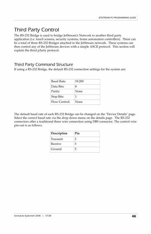
Third Party ControlThe RS-232 Bridge is used to bridge JetStream’s Network to another third party application (i.e. touch screens, security systems, home automation controllers). There canbe a total of three RS-232 Bridges attached to the JetStream network. These systems canthen control any of the JetStream devices with a simple ASCII protocol. This section willexplain the third p3arty protocol.
Third Party Command StructureIf using a RS-232 Bridge, the default RS-232 connection settings for the system are:
The default baud rate of each RS-232 Bridge can be changed on the "Device Details" page.Select the correct baud rate via the drop down menu on the details page. The RS-232 connectors offer a traditional three wire connection using DB9 connector. The control wirepin-out is as follows.
Baud Rate: 19,200
Data Bits: 8Parity: None
Stop Bits: 1
Flow Control: None
Description Pin
Transmit 2Receive 3
Ground 5
JETSTREAM PC PROGRAMMING GUIDE
CentraLite Systems® 2008 | 07.08 46
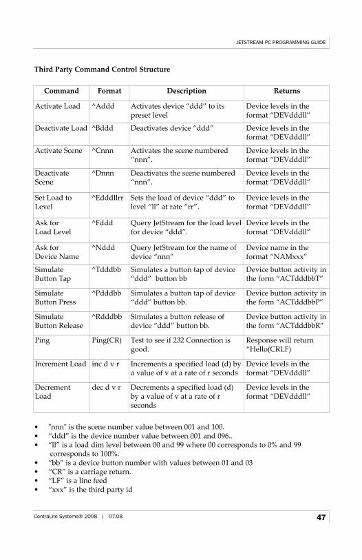
Third Party Command Control Structure
• "nnn" is the scene number value between 001 and 100. • “ddd” is the device number value between 001 and 096..• “ll” is a load dim level between 00 and 99 where 00 corresponds to 0% and 99
corresponds to 100%.• “bb” is a device button number with values between 01 and 03 • “CR” is a carriage return.• “LF” is a line feed • “xxx” is the third party id
Command Format Description Returns
Activate Load ^Addd Activates device “ddd” to its preset level
Device levels in the format “DEVdddll”
Deactivate Load ^Bddd Deactivates device “ddd” Device levels in the format “DEVdddll”
Activate Scene ^Cnnn Activates the scene numbered“nnn”.
Device levels in the format “DEVdddll”
DeactivateScene
^Dnnn Deactivates the scene numbered“nnn”.
Device levels in the format “DEVdddll”
Set Load toLevel
^Edddllrr Sets the load of device “ddd” tolevel “ll” at rate “rr”.
Device levels in the format “DEVdddll”
Ask for Load Level
^Fddd Query JetStream for the load levelfor device “ddd”.
Device levels in the format “DEVdddll”
Ask for Device Name
^Nddd Query JetStream for the name ofdevice “nnn”
Device name in the format “NAMxxx”
Simulate Button Tap
^Tdddbb Simulates a button tap of device“ddd” button bb
Device button activity inthe form “ACTdddbbT”
Simulate Button Press
^Pdddbb Simulates a button tap of device“ddd” button bb.
Device button activity inthe form “ACTdddbbP”
Simulate Button Release
^Rdddbb Simulates a button release ofdevice “ddd” button bb.
Device button activity inthe form “ACTdddbbR”
Ping Ping(CR) Test to see if 232 Connection isgood.
Response will return“Hello(CRLF)
Increment Load inc d v r Increments a specified load (d) bya value of v at a rate of r seconds
Device levels in the format “DEVdddll”
DecrementLoad
dec d v r Decrements a specified load (d)by a value of v at a rate of r seconds
Device levels in the format “DEVdddll”
JETSTREAM PC PROGRAMMING GUIDE
CentraLite Systems® 2008 | 07.08 47
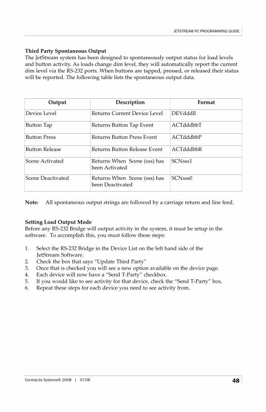
Third Party Spontaneous OutputThe JetStream system has been designed to spontaneously output status for load levelsand button activity. As loads change dim level, they will automatically report the currentdim level via the RS-232 ports. When buttons are tapped, pressed, or released their statuswill be reported. The following table lists the spontaneous output data.
Note: All spontaneous output strings are followed by a carriage return and line feed.
Setting Load Output ModeBefore any RS-232 Bridge will output activity in the system, it must be setup in the software. To accomplish this, you must follow these steps:
1. Select the RS-232 Bridge in the Device List on the left hand side of the JetStream Software.
2. Check the box that says “Update Third Party”3. Once that is checked you will see a new option available on the device page. 4. Each device will now have a “Send T-Party” checkbox.5. If you would like to see activity for that device, check the “Send T-Party” box.6. Repeat these steps for each device you need to see activity from.
Output Description Format
Device Level Returns Current Device Level DEVdddll
Button Tap Returns Button Tap Event ACTdddbbT
Button Press Returns Button Press Event ACTdddbbP
Button Release Returns Button Release Event ACTdddbbR
Scene Activated Returns When Scene (sss) hasbeen Activated
SCNsss1
Scene Deactivated Returns When Scene (sss) hasbeen Deactivated
SCNsss0
JETSTREAM PC PROGRAMMING GUIDE
CentraLite Systems® 2008 | 07.08 48

Factory DefaultingTo bring the RS-232 Bridge back to factory settings and to leave the current network it isattached to, you must factory default all settings. If you would like to factory default theRS-232 Bridge, please follow these steps.
1. Pull power from the RS-232 Bridge.2. Push and hold the button on the front right.3. While holding down the button, supply power back to the RS-232 Bridge.4. If button is depressed while powering up, you will see the Discovery LED
rapidly flashing.5. When the LED stops flashing, release the button.6. The Discovery LED will turn on for about 5 seconds (DO NOT PULL POWER
UNTIL LEDSTARTS SLOW BLINKING!!!)
7. When Discovery LED starts slow blinking, the RS-232 Bridge is back to factory settings.
JETSTREAM PC PROGRAMMING GUIDE
CentraLite Systems® 2008 | 07.08 49
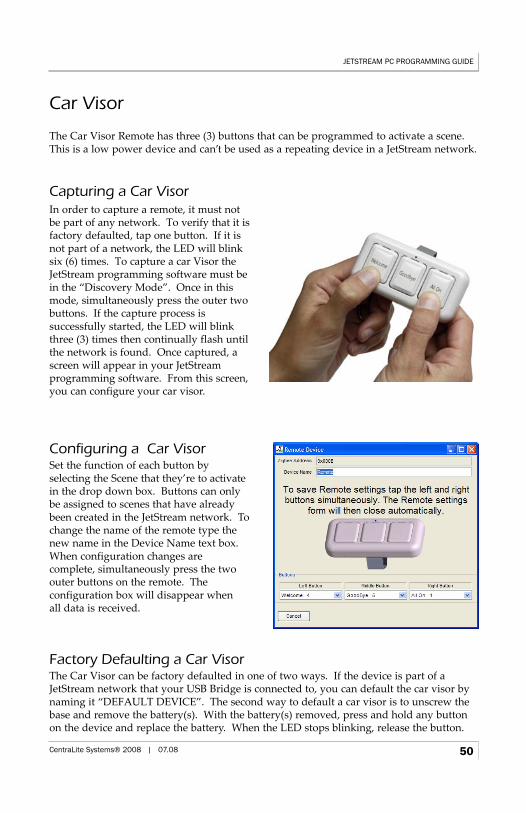
Car Visor
The Car Visor Remote has three (3) buttons that can be programmed to activate a scene.This is a low power device and can’t be used as a repeating device in a JetStream network.
Capturing a Car Visor
Factory Defaulting a Car VisorThe Car Visor can be factory defaulted in one of two ways. If the device is part of aJetStream network that your USB Bridge is connected to, you can default the car visor bynaming it “DEFAULT DEVICE”. The second way to default a car visor is to unscrew thebase and remove the battery(s). With the battery(s) removed, press and hold any buttonon the device and replace the battery. When the LED stops blinking, release the button.
JETSTREAM PC PROGRAMMING GUIDE
CentraLite Systems® 2008 | 07.08 50
In order to capture a remote, it must notbe part of any network. To verify that it isfactory defaulted, tap one button. If it isnot part of a network, the LED will blinksix (6) times. To capture a car Visor theJetStream programming software must bein the “Discovery Mode”. Once in thismode, simultaneously press the outer twobuttons. If the capture process is successfully started, the LED will blinkthree (3) times then continually flash untilthe network is found. Once captured, ascreen will appear in your JetStream programming software. From this screen,you can configure your car visor.
Configuring a Car VisorSet the function of each button byselecting the Scene that they’re to activatein the drop down box. Buttons can onlybe assigned to scenes that have alreadybeen created in the JetStream network. Tochange the name of the remote type thenew name in the Device Name text box.When configuration changes are complete, simultaneously press the twoouter buttons on the remote. The configuration box will disappear when all data is received.
Table Top Keypad
Table Top Remotes have eight (8) buttons that may be programmed to control loads andscenes. Table Top Remotes are high power devices that may be used as repeaters on aJetStream network.
Capturing a Table Top KaypadFirst, verify that the Table Top Kaypad is in its factory default state. This can be done byremoving and applying power to the device; if the device is defaulted the upper left LEDwill begin slow blinking. To capture a Table Top Keypad, JetStream programming software must be in “Discovery Mode”. Once the software is in this mode, and the TableTop Keypad has detected the network, the upper left LED will start fast blinking. Pressand hold the upper left button until the LED quits blinking to capture the device. Whenthe device attaches to the network, the following form will open which will allow you to configure the settings for the Table Top Keypad.
Configuring a Table Top KeypadTable Top Remote buttons may be configured to control remote loads and scenes in manyways. See the Button Settings section for more details about configuring buttons.
Factory Defaulting a Table Top KeypadTo factory default a Table Top Keypad, unplug the unit. Then, hold down the upper leftbutton and plug in the unit. The upper left LED will begin fast blinking. After five (5)seconds the LED will stop blinking, release the upper left button at this time. If successful, the device should begin slow blinking within a few seconds.
JETSTREAM PC PROGRAMMING GUIDE
CentraLite Systems® 2008 | 07.08 51
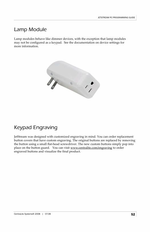
Lamp Module
Lamp modules behave like dimmer devices, with the exception that lamp modules may not be configured as a keypad. See the documentation on device settings for more information.
Keypad Engraving
JetStream was designed with customized engraving in mind. You can order replacementbutton covers that have custom engraving. The original buttons are replaced by removingthe button using a small flat-head screwdriver. The new custom buttons simply pop intoplace on the button guard. You can visit www.centralite.com/engraving to orderengraved buttons and visualize the final product.
JETSTREAM PC PROGRAMMING GUIDE
CentraLite Systems® 2008 | 07.08 52