Embed Size (px)
Citation preview
JNCIE-ENT V2.1 (2017) Demo workbook
Why this demo workbook?
This workbook is intended to give you an idea of what the
purched workbook looks like, and the way the original workbook
teaches you the curriculum.
Due to this, we hope you will understand that
some content will be covered.
If you have any questions, please don’t hesitate to contact me.
Jörg Buesink
Owner iNET ZERO
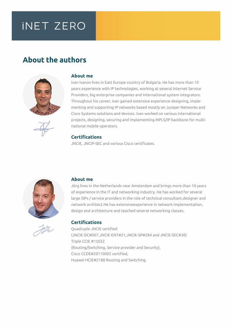
About the authors
About meIvan Ivanov lives in East Europe country of Bulgaria. He has more than 10
years experience with IP technologies, working at several Internet Service
Providers, big enterprise companies and International system integrators.
Throughout his career, Ivan gained extensive experience designing, imple-
menting and supporting IP networks based mostly on Juniper Networks and
Cisco Systems solutions and devices. Ivan worked on various international
projects, designing, securing and implementing MPLS/IP backbone for multi-
national mobile operators.
CertificationsJNCIE, JNCIP-SEC and various Cisco certificates.
About meJörg lives in the Netherlands near Amsterdam and brings more than 10 years
of experience in the IT and networking industry. He has worked for several
large ISPs / service providers in the role of technical consultant,designer and
network architect.He has extensiveexperience in network implementation,
design and architecture and teached several networking classes.
CertificationsQuadruple JNCIE certified
(JNCIE-DC#007,JNCIE-ENT#21,JNCIE-SP#284 and JNCIE-SEC#30)
Triple CCIE #15032
(Routing/Switching, Service provider and Security),
Cisco CCDE#20110002 certified,
Huawei HCIE#2188 Routing and Switching.
Table of Contents
General information
Exam strategy
Workbook updates and configuration files
iNET ZERO rack rental service
Chapter One: General System Features
Task 1: Initial System Configuration
Task 2: User Authentication and Authorization
Task 3: Syslog configuration
Task 4: SNMP Configuration
Task 5: Firewall filters
Chapter Two: L2 Switching and L2 Security
Task 1: L2 Switching Network Deployment
Task 2: Virtual Chassis
Task 3: VLAN Configuration
Task 4: Spanning Tree Configuration
Task 5: L2 Switching Security Features
Task 6: VRRP Configuration
Task 7: Provider bridging / Q in Q implementation
Chapter Three: IGP Routing
Task 1: Base Network and Virtual Router Deployment
Task 2: Multi Area OSPF Configuration
Task 3: External Configuration and Redistribution Policies
Task 4: Protocol-independent Routing and Routing Policies
Chapter Four: BGP Routing
Task 1: Base Network Deployment
Task 2: Internal BGP Configuration
Task 3: External BGP Configuration
Task 4: BGP Routing Policies
Task 5: Filter based routing
Chapter Five: Multicast Routing and Switching
Task 1: Base Network Deployment
Task 2: Multicast Routing and Switching
Chapter Six: Class of Service
Task 1: Base Network Deployment
Task 2: SRX Class of Service
Task 3: EX Class of Service
Chapter Seven: A Full Day Lab Challenge 1
Task 1: Initial System Configuration
Task 2: L2 Switching and Security
Task 3: IGP routing
Task 4: BGP Routing
Task 5: Multicast Routing and Switching
Task 6: Class of Service
Chapter Eight: A Full Day Lab Challenge 2
Task 1: Initial System Configuration
Task 2: Layer2 Configuration
Task 3: Protocol Independent Routing
Task 4: IGP Routing
Task 5: BGP Routing
Task 6: Multicast Routing
Task 7: Class of Service
Appendix – Chapter One: General System Features
Solution – Task 1: Initial System Configuration
Solution – Task 2: User Authentication and Authorization
Solution Task 3: Syslog configuration
Solution Task 4: SNMP Configuration
Solution Task 5: Firewall filters
Appendix - Chapter Two: L2 Switching and L2 Security
Solution - Task 1: L2 Switching Network Deployment
Solution - Task 2: Virtual Chassis
Solution - Task 3: VLAN Configuration
Solution - Task 4: Spanning Tree Configuration
Solution - Task 5: L2 Switching Security Features
Solution - Task 6: VRRP Configuration
Solution - Task 7: Provider bridging / Q in Q implementation
Appendix – Chapter Three: IGP Routing
Solution Task 1: Base Network and Virtual Router Deployment
Solution Task 2: Multi Area OSPF Configuration
Solution Task 3: External Configuration and Redistribution Policies
Solution Task 4: Protocol-independent Routing and Routing Policies
Appendix – Chapter Four: BGP Routing
Solution Task 1: Base Network Deployment
Solution Task 2: Internal BGP Configuration
Solution Task 3: External BGP Configuration
Solution Task 4: BGP Routing policies
Solution Task 5: Filter based routing
Appendix – Chapter Five: Multicast Routing and Switching
Solution Task 1: Base Network Deployment
Solution Task 2: Multicast Routing and Switching
Appendix – Chapter Six: Class of Service
Solution Task 1: Base Network Deployment
Solution Task 2: SRX Class of Service
Solution Task 3: EX Class of Service
Appendix – Chapter Seven: A Full Day Lab Challenge
Solution – Task 1: Initial System Configuration
Solution – Task 2: L2 Switching and Security
Solution – Task 3: IGP routing
Solution – Task 3: BGP Routing
Solution – Task 5: Multicast Routing and Switching
Solution – Task 6: Class of Service
Appendix – Chapter Eight: A Full Day Lab Challenge II
Task 1: Initial System Configuration
Task 2: Layer2 Configuration
Task 3: Protocol Independent Routing
Task 4: IGP Routing
Task 5: BGP Routing
Task 6: Multicast Routing
Task 7: Class of Service
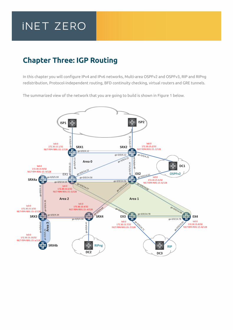
Chapter Three: IGP Routing
In this chapter you will configure IPv4 and IPv6 networks, Multi-area OSPFv2 and OSPFv3, RIP and RIPng
redistribution, Protocol-independent routing, BFD continuity checking, virtual routers and GRE tunnels.
The summarized view of the network that you are going to build is shown in Figure 1 below.
ISP1
ge-0
/0/4
.14
SRX1
ISP2
SRX2
SRX3 SRX4
EX1 EX2
EX3 EX4
SRX4b
SRX4a
DC1
DC2 DC3
Area 0
Area 1Area 2
Area
3
ge-0/0/4.12
ge-0
/0/4
.13
ge-0/0/4.12
ge-0
/0/4
.24
ge-0
/0/4
.22
ge-0/0/4.23
ge-0
/0/1
4.13
ge-0/0/14.23
ge-0/0/14.56
ge-0/0/14.57
ge-0/0/14.59
ge-0
/0/1
4.24
ge-0/0/14.56
ge-0/0/14.61
ge-0/0/14.68ge-0/0/14.64
ge-0/0/14.57
ge-0/0/14.68ge-0/0/14.78
ge-0/0/14.78ge-0/0/14.71 ge
-0/0/1
4.81
ge-0
/0/4
.39
ge-0/0/4.34
ge-0
/0/4
.31
ge-0/0/4.34
ge-0/0/4.64
ge-0
/0/4
.41
ge-0/0/5.59
ge-0
/0/5
.39
ge-0
/0/5
.31
ge-0/0/4.25
lo0.0172.30.15.1/32
fd17:f0f4:f691:15::1/128
lo0.0172.30.15.2/32
fd17:f0f4:f691:15::2/128
lo0.0172.30.15.6/32
fd17:f0f4:f691:15::6/128lo0.0
172.30.15.5/32fd17:f0f4:f691:15::5/128
lo0.0172.30.15.9/32
fd17:f0f4:f691:15::9/128
lo0.0172.30.15.3/32
fd17:f0f4:f691:15::3/128
lo0.0172.30.15.10/32
fd17:f0f4:f691:15::a/128
lo0.0172.30.15.4/32
fd17:f0f4:f691:15::4/128
lo0.0172.30.15.7/32
fd17:f0f4:f691:15::7/128
lo0.0172.30.15.8/32
fd17:f0f4:f691:15::8/128
RIPng
OSPFv2
RIP
Task 1: Base Network and Virtual Router Deployment
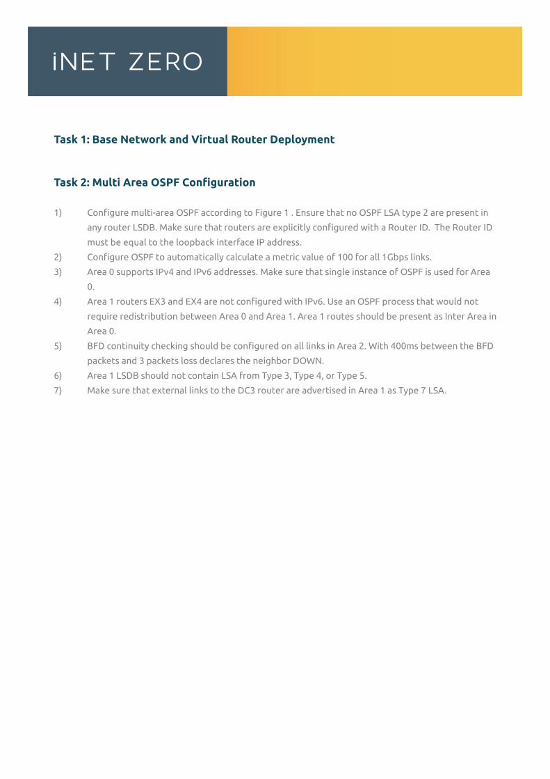
Task 2: Multi Area OSPF Configuration
1) Configure multi-area OSPF according to Figure 1 . Ensure that no OSPF LSA type 2 are present in
any router LSDB. Make sure that routers are explicitly configured with a Router ID. The Router ID
must be equal to the loopback interface IP address.
2) Configure OSPF to automatically calculate a metric value of 100 for all 1Gbps links.
3) Area 0 supports IPv4 and IPv6 addresses. Make sure that single instance of OSPF is used for Area
0.
4) Area 1 routers EX3 and EX4 are not configured with IPv6. Use an OSPF process that would not
require redistribution between Area 0 and Area 1. Area 1 routes should be present as Inter Area in
Area 0.
5) BFD continuity checking should be configured on all links in Area 2. With 400ms between the BFD
packets and 3 packets loss declares the neighbor DOWN.
6) Area 1 LSDB should not contain LSA from Type 3, Type 4, or Type 5.
7) Make sure that external links to the DC3 router are advertised in Area 1 as Type 7 LSA.
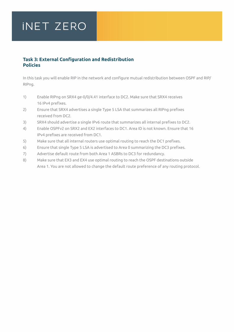
Task 3: External Configuration and Redistribution Policies
In this task you will enable RIP in the network and configure mutual redistribution between OSPF and RIP/
RIPng.
1) Enable RIPng on SRX4 ge-0/0/4.41 interface to DC2. Make sure that SRX4 receives
16 IPv4 prefixes.
2) Ensure that SRX4 advertises a single Type 5 LSA that summarizes all RIPng prefixes
received from DC2.
3) SRX4 should advertise a single IPv6 route that summarizes all internal prefixes to DC2.
4) Enable OSPFv2 on SRX2 and EX2 interfaces to DC1. Area ID is not known. Ensure that 16
IPv4 prefixes are received from DC1.
5) Make sure that all internal routers use optimal routing to reach the DC1 prefixes.
6) Ensure that single Type 5 LSA is advertised to Area 0 summarizing the DC3 prefixes.
7) Advertise default route from both Area 1 ASBRs to DC3 for redundancy.
8) Make sure that EX3 and EX4 use optimal routing to reach the OSPF destinations outside
Area 1. You are not allowed to change the default route preference of any routing protocol.
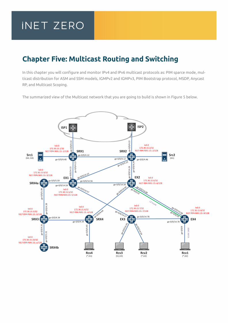
Chapter Five: Multicast Routing and Switching
In this chapter you will configure and monitor IPv4 and IPv6 multicast protocols as: PIM sparce mode, mul-
ticast distribution for ASM and SSM models, IGMPv2 and IGMPv3, PIM Bootstrap protocol, MSDP, Anycast
RP, and Multicast Scoping.
The summarized view of the Multicast network that you are going to build is shown in Figure 5 below.
ISP1
ge-0
/0/4
.14
SRX1
ISP2
SRX2
SRX3 SRX4
EX1 EX2
EX3 EX4
SRX4b
SRX4a
ge-0/0/4.12
ge-0
/0/4
.13
ge-0/0/4.12
ge-0
/0/4
.24
ge-0
/0/4
.22
ge-0/0/4.23
ge-0
/0/1
4.13
ge-0/0/14.23
ge-0/0/14.56
ge-0/0/14.57
ge-0/0/14.59
ge-0
/0/1
4.24
ge-0/0/14.56ge-0/0/14.68
ge-0/0/14.64
ge-0/0/14.57
ge-0/0/14.68
ge-0/0/14.78
ge-0/0/14.78
ge-0
/0/4
.39
ge-0/0/4.34
ge-0
/0/4
.31
ge-0/0/4.34
ge-0/0/4.64
ge-0/0/5.59
ge-0
/0/5
.39
ge-0
/0/5
.31
lo0.0172.30.15.1/32
fd17:f0f4:f691:15::1/128
lo0.0172.30.15.2/32
fd17:f0f4:f691:15::2/128
lo0.0172.30.15.6/32
fd17:f0f4:f691:15::6/128
lo0.0172.30.15.5/32
fd17:f0f4:f691:15::5/128
lo0.0172.30.15.9/32
fd17:f0f4:f691:15::9/128
lo0.0172.30.15.3/32
fd17:f0f4:f691:15::3/128
lo0.0172.30.15.10/32
fd17:f0f4:f691:15::a/128
lo0.0172.30.15.4/32
fd17:f0f4:f691:15::4/128
lo0.0172.30.15.7/32
fd17:f0f4:f691:15::7/128lo0.0
172.30.15.8/32fd17:f0f4:f691:15::8/128
ge-0
/0/9
Rcv1(*,G2)
Src2(G1)
Src1(G2, G3)
VLAN
140
0
Rcv4(*,G1)
Rcv2(*,G2)
Rcv3(S1,G3)
ge-0/0/4.40 ge-0/0/4.46
ge-0
/0/4
.45
ge-0
/0/1
4.43
ge-0/0/14.44
ge-0/0/19
ge-0/0/19
L2 trunk
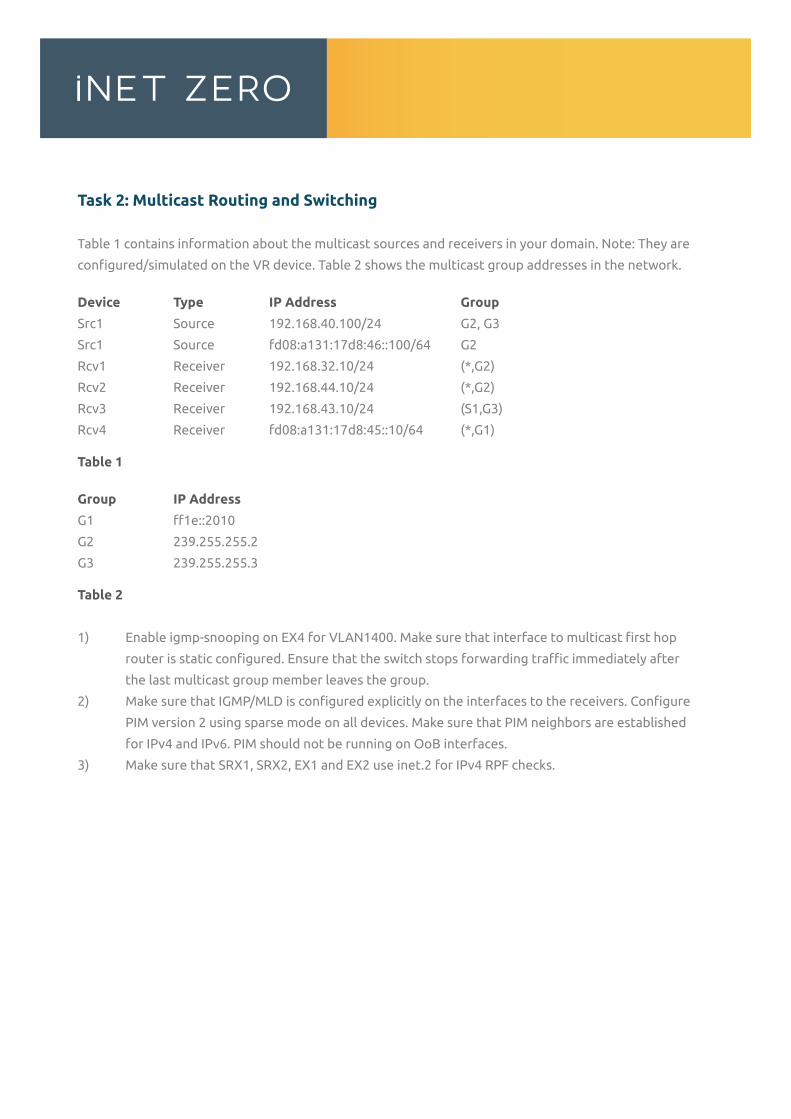
Task 2: Multicast Routing and Switching
Table 1 contains information about the multicast sources and receivers in your domain. Note: They are
configured/simulated on the VR device. Table 2 shows the multicast group addresses in the network.
Device Type IP Address Group
Src1 Source 192.168.40.100/24 G2, G3
Src1 Source fd08:a131:17d8:46::100/64 G2
Rcv1 Receiver 192.168.32.10/24 (*,G2)
Rcv2 Receiver 192.168.44.10/24 (*,G2)
Rcv3 Receiver 192.168.43.10/24 (S1,G3)
Rcv4 Receiver fd08:a131:17d8:45::10/64 (*,G1)
Table 1
Group IP Address
G1 ff1e::2010
G2 239.255.255.2
G3 239.255.255.3
Table 2
1) Enable igmp-snooping on EX4 for VLAN1400. Make sure that interface to multicast first hop
router is static configured. Ensure that the switch stops forwarding traffic immediately after
the last multicast group member leaves the group.
2) Make sure that IGMP/MLD is configured explicitly on the interfaces to the receivers. Configure
PIM version 2 using sparse mode on all devices. Make sure that PIM neighbors are established
for IPv4 and IPv6. PIM should not be running on OoB interfaces.
3) Make sure that SRX1, SRX2, EX1 and EX2 use inet.2 for IPv4 RPF checks.
Appendix – Chapter Four: BGP Routing
Solution Task 2: Internal BGP Configuration
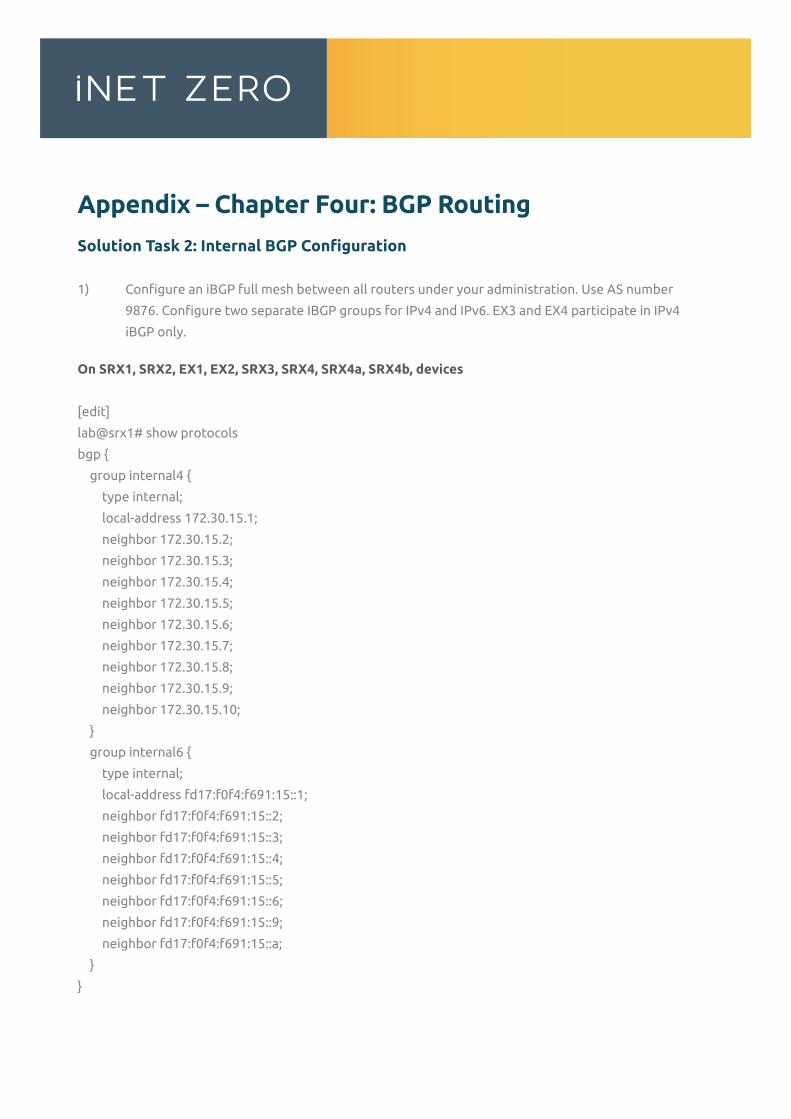
1) Configure an iBGP full mesh between all routers under your administration. Use AS number
9876. Configure two separate IBGP groups for IPv4 and IPv6. EX3 and EX4 participate in IPv4
iBGP only.
On SRX1, SRX2, EX1, EX2, SRX3, SRX4, SRX4a, SRX4b, devices
[edit]
lab@srx1# show protocols
bgp {
group internal4 {
type internal;
local-address 172.30.15.1;
neighbor 172.30.15.2;
neighbor 172.30.15.3;
neighbor 172.30.15.4;
neighbor 172.30.15.5;
neighbor 172.30.15.6;
neighbor 172.30.15.7;
neighbor 172.30.15.8;
neighbor 172.30.15.9;
neighbor 172.30.15.10;
}
group internal6 {
type internal;
local-address fd17:f0f4:f691:15::1;
neighbor fd17:f0f4:f691:15::2;
neighbor fd17:f0f4:f691:15::3;
neighbor fd17:f0f4:f691:15::4;
neighbor fd17:f0f4:f691:15::5;
neighbor fd17:f0f4:f691:15::6;
neighbor fd17:f0f4:f691:15::9;
neighbor fd17:f0f4:f691:15::a;
}
}
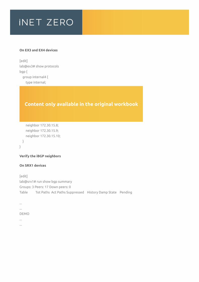
On EX3 and EX4 devices
[edit]
lab@ex3# show protocols
bgp {
group internal4 {
type internal;
local-address 172.30.15.7;
neighbor 172.30.15.1;
neighbor 172.30.15.2;
neighbor 172.30.15.3;
neighbor 172.30.15.4;
neighbor 172.30.15.5;
neighbor 172.30.15.6;
neighbor 172.30.15.8;
neighbor 172.30.15.9;
neighbor 172.30.15.10;
}
}
Verify the iBGP neighbors
On SRX1 devices
[edit]
lab@srx1# run show bgp summary
Groups: 3 Peers: 17 Down peers: 0
Table Tot Paths Act Paths Suppressed History Damp State Pending
...
...
DEMO
...
...
Content only available in the original workbook
[edit]
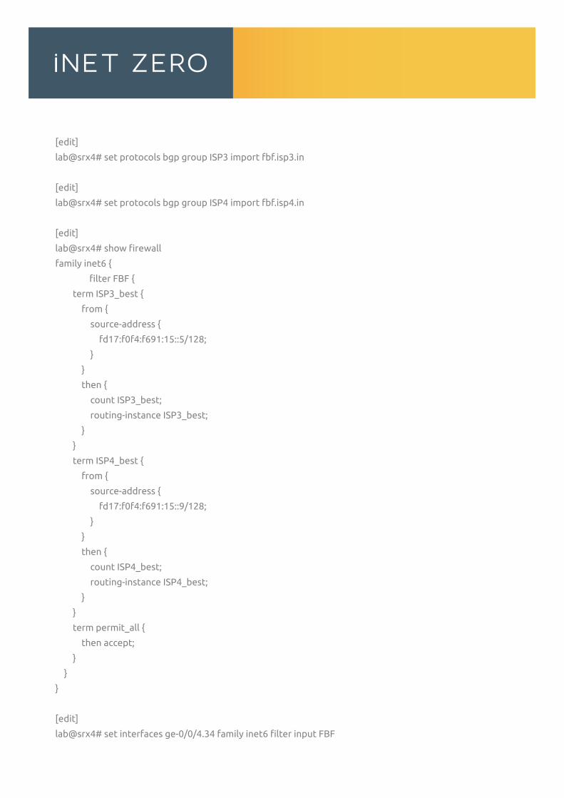
lab@srx4# set protocols bgp group ISP3 import fbf.isp3.in
[edit]
lab@srx4# set protocols bgp group ISP4 import fbf.isp4.in
[edit]
lab@srx4# show firewall
family inet6 {
filter FBF {
term ISP3_best {
from {
source-address {
fd17:f0f4:f691:15::5/128;
}
}
then {
count ISP3_best;
routing-instance ISP3_best;
}
}
term ISP4_best {
from {
source-address {
fd17:f0f4:f691:15::9/128;
}
}
then {
count ISP4_best;
routing-instance ISP4_best;
}
}
term permit_all {
then accept;
}
}
}
[edit]
lab@srx4# set interfaces ge-0/0/4.34 family inet6 filter input FBF
[edit]
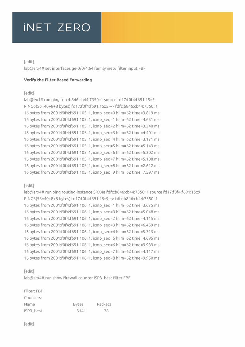
lab@srx4# set interfaces ge-0/0/4.64 family inet6 filter input FBF
Verify the Filter Based Forwarding
[edit]
lab@ex1# run ping fdfc:b846:cb44:7350::1 source fd17:f0f4:f691:15::5
PING6(56=40+8+8 bytes) fd17:f0f4:f691:15::5 --> fdfc:b846:cb44:7350::1
16 bytes from 2001:f0f4:f691:105::1, icmp_seq=0 hlim=62 time=3.819 ms
16 bytes from 2001:f0f4:f691:105::1, icmp_seq=1 hlim=62 time=4.651 ms
16 bytes from 2001:f0f4:f691:105::1, icmp_seq=2 hlim=62 time=3.240 ms
16 bytes from 2001:f0f4:f691:105::1, icmp_seq=3 hlim=62 time=4.401 ms
16 bytes from 2001:f0f4:f691:105::1, icmp_seq=4 hlim=62 time=3.171 ms
16 bytes from 2001:f0f4:f691:105::1, icmp_seq=5 hlim=62 time=5.143 ms
16 bytes from 2001:f0f4:f691:105::1, icmp_seq=6 hlim=62 time=5.302 ms
16 bytes from 2001:f0f4:f691:105::1, icmp_seq=7 hlim=62 time=5.108 ms
16 bytes from 2001:f0f4:f691:105::1, icmp_seq=8 hlim=62 time=2.622 ms
16 bytes from 2001:f0f4:f691:105::1, icmp_seq=9 hlim=62 time=7.597 ms
[edit]
lab@srx4# run ping routing-instance SRX4a fdfc:b846:cb44:7350::1 source fd17:f0f4:f691:15::9
PING6(56=40+8+8 bytes) fd17:f0f4:f691:15::9 --> fdfc:b846:cb44:7350::1
16 bytes from 2001:f0f4:f691:106::1, icmp_seq=1 hlim=62 time=3.675 ms
16 bytes from 2001:f0f4:f691:106::1, icmp_seq=0 hlim=62 time=5.048 ms
16 bytes from 2001:f0f4:f691:106::1, icmp_seq=2 hlim=62 time=4.115 ms
16 bytes from 2001:f0f4:f691:106::1, icmp_seq=3 hlim=62 time=6.459 ms
16 bytes from 2001:f0f4:f691:106::1, icmp_seq=4 hlim=62 time=5.313 ms
16 bytes from 2001:f0f4:f691:106::1, icmp_seq=5 hlim=62 time=4.695 ms
16 bytes from 2001:f0f4:f691:106::1, icmp_seq=6 hlim=62 time=9.989 ms
16 bytes from 2001:f0f4:f691:106::1, icmp_seq=7 hlim=62 time=4.117 ms
16 bytes from 2001:f0f4:f691:106::1, icmp_seq=8 hlim=62 time=9.950 ms
[edit]
lab@srx4# run show firewall counter ISP3_best filter FBF
Filter: FBF
Counters:
Name Bytes Packets
ISP3_best 3141 38
[edit]
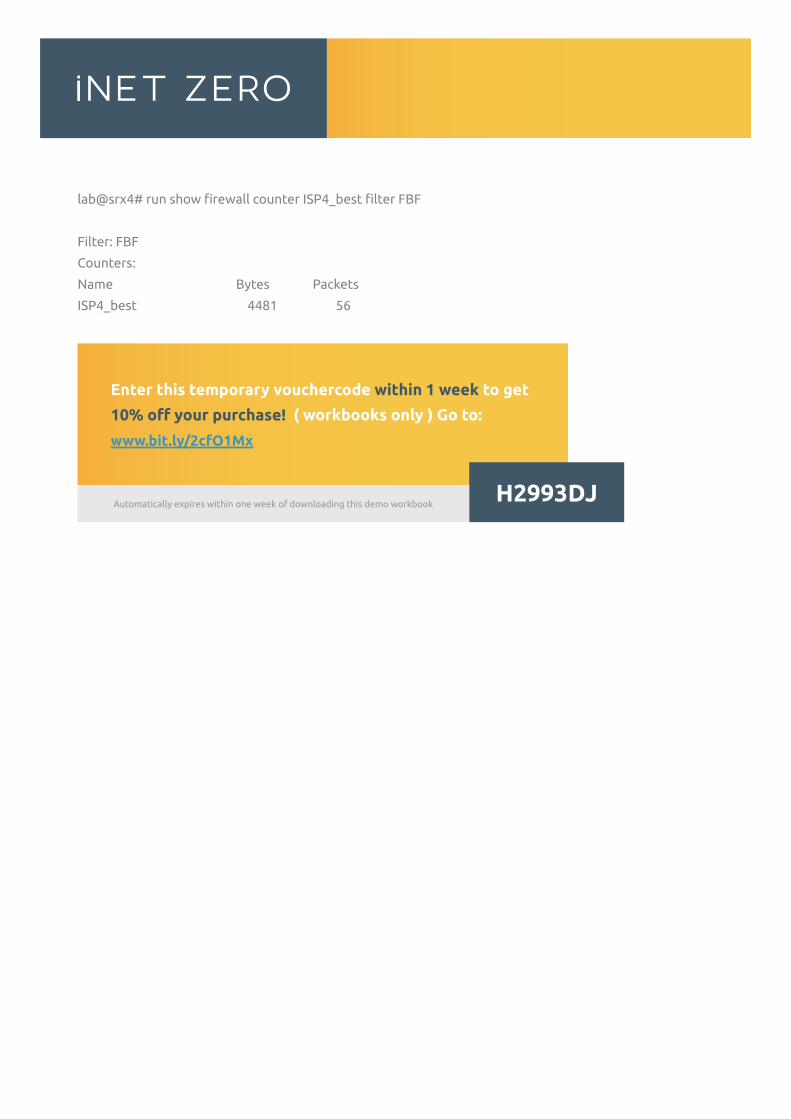
lab@srx4# run show firewall counter ISP4_best filter FBF
Filter: FBF
Counters:
Name Bytes Packets
ISP4_best 4481 56
...
...
DEMO
...
...
Enter this temporary vouchercode within 1 week to get
10% off your purchase! ( workbooks only ) Go to:
www.bit.ly/2cfO1Mx
H2993DJAutomatically expires within one week of downloading this demo workbook
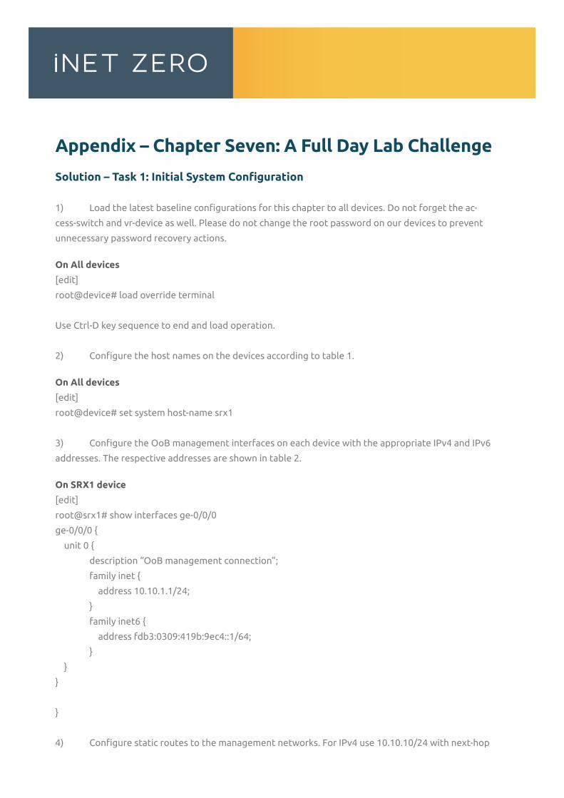
Appendix – Chapter Seven: A Full Day Lab Challenge
Solution – Task 1: Initial System Configuration
1) Load the latest baseline configurations for this chapter to all devices. Do not forget the ac-
cess-switch and vr-device as well. Please do not change the root password on our devices to prevent
unnecessary password recovery actions.
On All devices
[edit]
root@device# load override terminal
Use Ctrl-D key sequence to end and load operation.
2) Configure the host names on the devices according to table 1.
On All devices
[edit]
root@device# set system host-name srx1
3) Configure the OoB management interfaces on each device with the appropriate IPv4 and IPv6
addresses. The respective addresses are shown in table 2.
On SRX1 device
[edit]
root@srx1# show interfaces ge-0/0/0
ge-0/0/0 {
unit 0 {
description “OoB management connection”;
family inet {
address 10.10.1.1/24;
}
family inet6 {
address fdb3:0309:419b:9ec4::1/64;
}
}
}
}
4) Configure static routes to the management networks. For IPv4 use 10.10.10/24 with next-hop
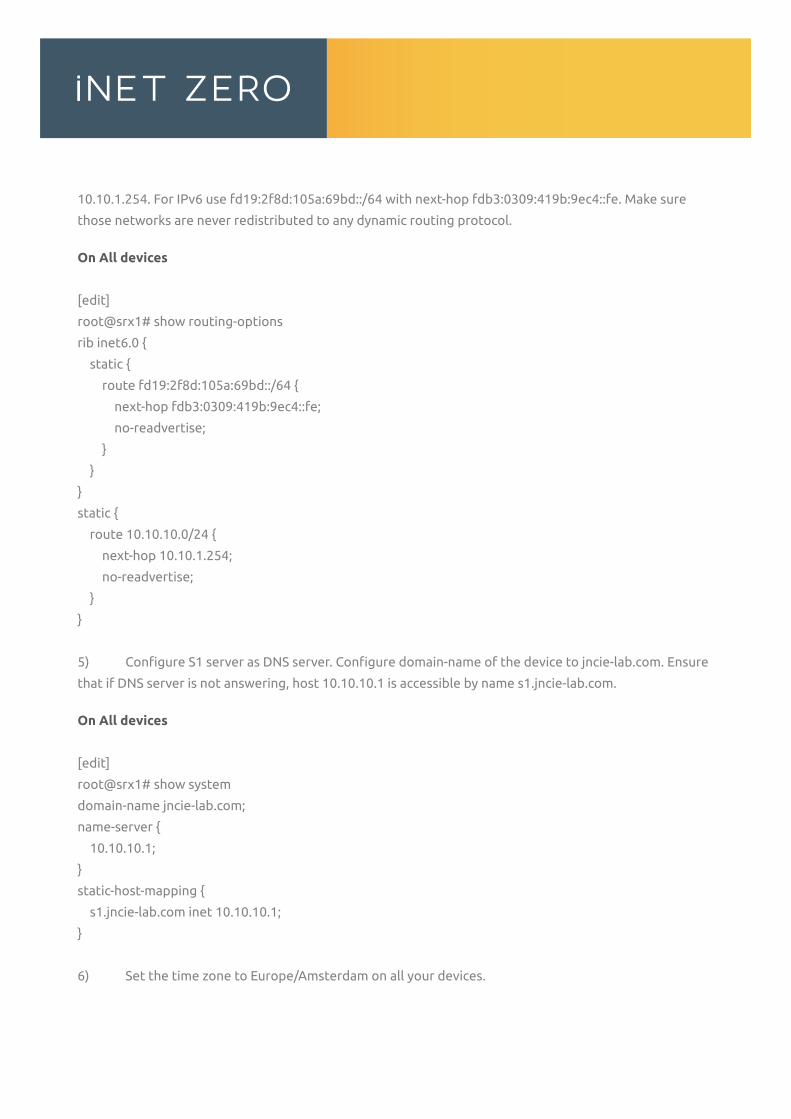
10.10.1.254. For IPv6 use fd19:2f8d:105a:69bd::/64 with next-hop fdb3:0309:419b:9ec4::fe. Make sure
those networks are never redistributed to any dynamic routing protocol.
On All devices
[edit]
root@srx1# show routing-options
rib inet6.0 {
static {
route fd19:2f8d:105a:69bd::/64 {
next-hop fdb3:0309:419b:9ec4::fe;
no-readvertise;
}
}
}
static {
route 10.10.10.0/24 {
next-hop 10.10.1.254;
no-readvertise;
}
}
5) Configure S1 server as DNS server. Configure domain-name of the device to jncie-lab.com. Ensure
that if DNS server is not answering, host 10.10.10.1 is accessible by name s1.jncie-lab.com.
On All devices
[edit]
root@srx1# show system
domain-name jncie-lab.com;
name-server {
10.10.10.1;
}
static-host-mapping {
s1.jncie-lab.com inet 10.10.10.1;
}
6) Set the time zone to Europe/Amsterdam on all your devices.
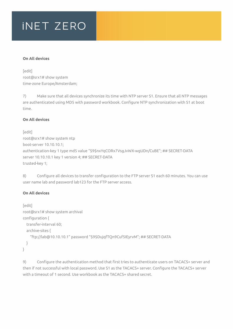
On All devices
[edit]
root@srx1# show system
time-zone Europe/Amsterdam;
7) Make sure that all devices synchronize its time with NTP server S1. Ensure that all NTP messages
are authenticated using MD5 with password workbook. Configure NTP synchronization with S1 at boot
time.
On All devices
[edit]
root@srx1# show system ntp
boot-server 10.10.10.1;
authentication-key 1 type md5 value “$9$nxYqCORx7VsgJvWX-wgUDn/CuBE”; ## SECRET-DATA
server 10.10.10.1 key 1 version 4; ## SECRET-DATA
trusted-key 1;
8) Configure all devices to transfer configuration to the FTP server S1 each 60 minutes. You can use
user name lab and password lab123 for the FTP server access.
On All devices
[edit]
root@srx1# show system archival
configuration {
transfer-interval 60;
archive-sites {
“ftp://[email protected]” password “$9$DujqfTQn9Cuf5IEyrvM”; ## SECRET-DATA
}
}
9) Configure the authentication method that first tries to authenticate users on TACACS+ server and
then if not successful with local password. Use S1 as the TACACS+ server. Configure the TACACS+ server
with a timeout of 1 second. Use workbook as the TACACS+ shared secret.
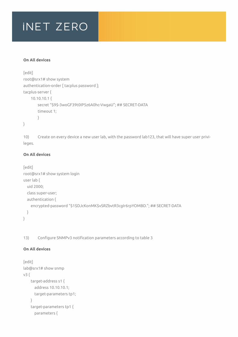
On All devices
[edit]
root@srx1# show system
authentication-order [ tacplus password ];
tacplus-server {
10.10.10.1 {
secret “$9$-3woGF39t0IP5z6A0hc-VwgaU”; ## SECRET-DATA
timeout 1;
}
}
10) Create on every device a new user lab, with the password lab123, that will have super user privi-
leges.
On All devices
[edit]
root@srx1# show system login
user lab {
uid 2000;
class super-user;
authentication {
encrypted-password “$1$DJcKonMK$vSRZbvtR3cgIr6rpYOMBD.”; ## SECRET-DATA
}
}
13) Configure SNMPv3 notification parameters according to table 3
On All devices
[edit]
lab@srx1# show snmp
v3 {
target-address s1 {
address 10.10.10.1;
target-parameters tp1;
}
target-parameters tp1 {
parameters {
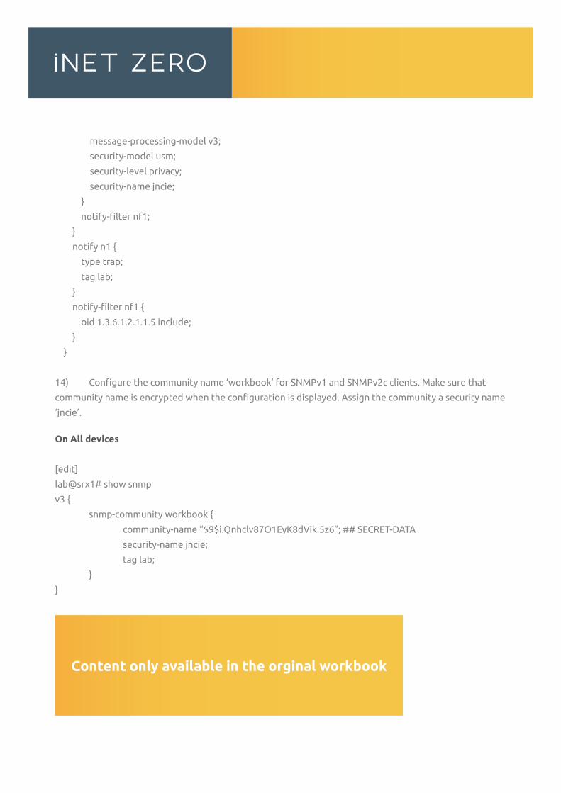
message-processing-model v3;
security-model usm;
security-level privacy;
security-name jncie;
}
notify-filter nf1;
}
notify n1 {
type trap;
tag lab;
}
notify-filter nf1 {
oid 1.3.6.1.2.1.1.5 include;
}
}
14) Configure the community name ‘workbook’ for SNMPv1 and SNMPv2c clients. Make sure that
community name is encrypted when the configuration is displayed. Assign the community a security name
‘jncie’.
On All devices
[edit]
lab@srx1# show snmp
v3 {
snmp-community workbook {
community-name “$9$i.Qnhclv87O1EyK8dVik.5z6”; ## SECRET-DATA
security-name jncie;
tag lab;
}
}
...
...
DEMO
...
...Content only available in the orginal workbook
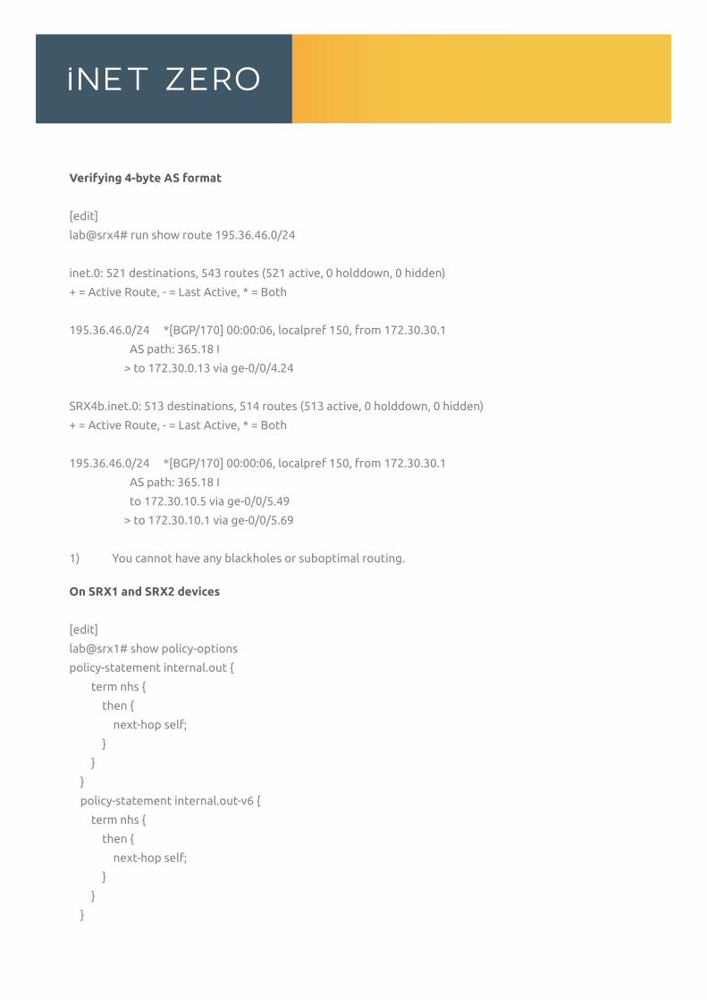
Verifying 4-byte AS format
[edit]
lab@srx4# run show route 195.36.46.0/24
inet.0: 521 destinations, 543 routes (521 active, 0 holddown, 0 hidden)
+ = Active Route, - = Last Active, * = Both
195.36.46.0/24 *[BGP/170] 00:00:06, localpref 150, from 172.30.30.1
AS path: 365.18 I
> to 172.30.0.13 via ge-0/0/4.24
SRX4b.inet.0: 513 destinations, 514 routes (513 active, 0 holddown, 0 hidden)
+ = Active Route, - = Last Active, * = Both
195.36.46.0/24 *[BGP/170] 00:00:06, localpref 150, from 172.30.30.1
AS path: 365.18 I
to 172.30.10.5 via ge-0/0/5.49
> to 172.30.10.1 via ge-0/0/5.69
1) You cannot have any blackholes or suboptimal routing.
On SRX1 and SRX2 devices
[edit]
lab@srx1# show policy-options
policy-statement internal.out {
term nhs {
then {
next-hop self;
}
}
}
policy-statement internal.out-v6 {
term nhs {
then {
next-hop self;
}
}
}
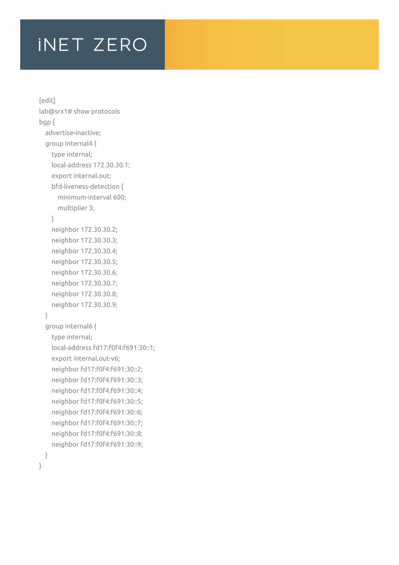
[edit]
lab@srx1# show protocols
bgp {
advertise-inactive;
group internal4 {
type internal;
local-address 172.30.30.1;
export internal.out;
bfd-liveness-detection {
minimum-interval 600;
multiplier 3;
}
neighbor 172.30.30.2;
neighbor 172.30.30.3;
neighbor 172.30.30.4;
neighbor 172.30.30.5;
neighbor 172.30.30.6;
neighbor 172.30.30.7;
neighbor 172.30.30.8;
neighbor 172.30.30.9;
}
group internal6 {
type internal;
local-address fd17:f0f4:f691:30::1;
export internal.out-v6;
neighbor fd17:f0f4:f691:30::2;
neighbor fd17:f0f4:f691:30::3;
neighbor fd17:f0f4:f691:30::4;
neighbor fd17:f0f4:f691:30::5;
neighbor fd17:f0f4:f691:30::6;
neighbor fd17:f0f4:f691:30::7;
neighbor fd17:f0f4:f691:30::8;
neighbor fd17:f0f4:f691:30::9;
}
}
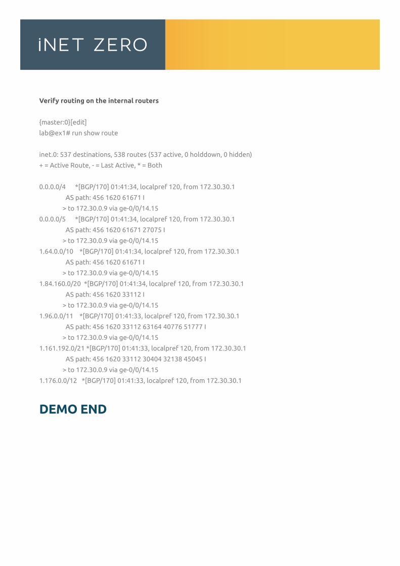
Verify routing on the internal routers
{master:0}[edit]
lab@ex1# run show route
inet.0: 537 destinations, 538 routes (537 active, 0 holddown, 0 hidden)
+ = Active Route, - = Last Active, * = Both
0.0.0.0/4 *[BGP/170] 01:41:34, localpref 120, from 172.30.30.1
AS path: 456 1620 61671 I
> to 172.30.0.9 via ge-0/0/14.15
0.0.0.0/5 *[BGP/170] 01:41:34, localpref 120, from 172.30.30.1
AS path: 456 1620 61671 27075 I
> to 172.30.0.9 via ge-0/0/14.15
1.64.0.0/10 *[BGP/170] 01:41:34, localpref 120, from 172.30.30.1
AS path: 456 1620 61671 I
> to 172.30.0.9 via ge-0/0/14.15
1.84.160.0/20 *[BGP/170] 01:41:34, localpref 120, from 172.30.30.1
AS path: 456 1620 33112 I
> to 172.30.0.9 via ge-0/0/14.15
1.96.0.0/11 *[BGP/170] 01:41:33, localpref 120, from 172.30.30.1
AS path: 456 1620 33112 63164 40776 51777 I
> to 172.30.0.9 via ge-0/0/14.15
1.161.192.0/21 *[BGP/170] 01:41:33, localpref 120, from 172.30.30.1
AS path: 456 1620 33112 30404 32138 45045 I
> to 172.30.0.9 via ge-0/0/14.15
1.176.0.0/12 *[BGP/170] 01:41:33, localpref 120, from 172.30.30.1
DEMO END
This workbook was developed by iNET ZERO.
All rights reserved. No part of this publication may be reproduced or distributed in any form or
by any means without the prior written permission of iNET ZERO a registered company in the
Netherlands. This product cannot be used by or transferred to any other person.
You are not allowed to rent, lease, loan or sell iNET ZERO training products including this
workbook and its configurations. You are not allowed to modify, copy, upload, email or
distribute this workbook in any way. This product may only be used and printed for your
own personal use and may not be used in any commercial way. Juniper (c), Juniper Networks
inc, JNCIE, JNCIP, JNCIS, JNCIA, Juniper Networks Certified Internet Expert, are registered
trademarks of Juniper Networks, Inc.

This original workbooks helped over more than 340+ people achieve the expert certification
Unfortunately you have reached the end of this demo workbook.
Enter this temporary vouchercode within 1 week to get
10% off your purchase! ( workbooks only ) Go to:
www.bit.ly/2cfO1Mx
H2993DJAutomatically expires within one week of downloading this demo workbook