Embed Size (px)
Citation preview
Joint Tactics,Techniques, and Procedures
for Laser DesignationOperations
Joint Pub 3-09.1
28 May 1999
PREFACE
i
1. Scope
This publication provides joint tactics,techniques, and procedures for employinglight amplification by stimulated emission ofradiation (laser) target designators, laseracquisition devices, and laser-guidedmunitions. It describes joint laser planning,coordination procedures, capabilities, andlimitations.
2. Purpose
This publication has been prepared underthe direction of the Chairman of the JointChiefs of Staff. It sets forth doctrine andselected joint tactics, techniques, andprocedures (JTTP) to govern the jointactivities and performance of the ArmedForces of the United States in joint operationsand provides the doctrinal basis for USmilitary involvement in multinational andinteragency operations. It provides militaryguidance for the exercise of authority bycombatant commanders and other jointforce commanders and prescribes doctrineand selected tactics, techniques, andprocedures for joint operations and training.It provides military guidance for use by theArmed Forces in preparing their appropriateplans. It is not the intent of this publication torestrict the authority of the joint forcecommander (JFC) from organizing the forceand executing the mission in a manner the JFCdeems most appropriate to ensure unity ofeffort in the accomplishment of the overallmission.
3. Application
a. Doctrine and se lec ted tac t i cs ,techniques, and procedures and guidanceestablished in this publication apply to thecommanders of combatant commands,subunified commands, joint task forces, andsubordinate components of these commands.These principles and guidance also may applywhen significant forces of one Service areattached to forces of another Service or whensignificant forces of one Service supportforces of another Service.
b. The guidance in this publication isauthoritative; as such, this doctrine (or JTTP)will be followed except when, in the judgmentof the commander, exceptional circumstancesdictate otherwise. If conflicts arise betweenthe contents of this publication and thecontents of Service publications, thispublication will take precedence for theactivities of joint forces unless the Chairmanof the Joint Chiefs of Staff, normally incoordination with the other members of theJoint Chiefs of Staff, has provided morecurrent and specific guidance. Commandersof forces operating as part of a multinational(alliance or coalition) military commandshould follow multinational doctrine andprocedures ratified by the United States. Fordoctrine and procedures not ratified by theUnited States, commanders should evaluateand follow the multinational command’sdoctrine and procedures where applicable andwhere consistent with US policies andprocedures.
V. E. CLARKVice Admiral, US NavyDirector, Joint Staff
For the Chairman of the Joint Chiefs of Staff:

ii
Preface
Joint Pub 3-09.1
Intentionally Blank
TABLE OF CONTENTS
iii
PAGE
EXECUTIVE SUMMARY .......................................................................................... vii
CHAPTER ICONCEPT
• Introduction.............................................................................................................. I-1• Laser Use on the Battlefield...................................................................................... I-1• Laser Target Acquisition........................................................................................... I-3• Friendly Forces Safety Considerations...................................................................... I-4
CHAPTER IIPLANNING CONSIDERATIONS
• Laser Designator Characteristics.............................................................................. II-1• Environmental Considerations................................................................................. II-7• Seeker Characteristics.............................................................................................. II-8• Seeker Types............................................................................................................ II-9• Target Types............................................................................................................. II-9• Designator Operator Positioning Considerations.................................................... II-10• Offset Laser Designation........................................................................................ II-10• Delayed Laser Designation for LGBs..................................................................... II-10• Delayed Laser Designation for HELLFIRE............................................................ II-11• Redundant Laser Designation................................................................................. II-11• Laser Systems Descriptions.................................................................................... II-12
CHAPTER IIIPROCEDURES
• General Procedures................................................................................................ III-1• Laser Designation for Artillery............................................................................... III-4• Laser Designation for CAS.................................................................................... III-6• Rotary-Wing Close Air Support............................................................................ III-14• Laser Designation for Non-CAS Air Attacks......................................................... III-16
CHAPTER IVLASER CODES
• Introduction........................................................................................................... IV-1• Management of Coded Laser Systems.................................................................... IV-1• Laser Coding in Conjunction With LGBs............................................................... IV-2• Coding Prioritization.............................................................................................. IV-2
iv
Table of Contents
Joint Pub 3-09.1
CHAPTER VSAFETY
• General................................................................................................................... V-1• Laser Eye Safety..................................................................................................... V-1• Fratricide................................................................................................................ V-2• Organizational Safety Considerations...................................................................... V-3
APPENDIX
A Laser Equipment Descriptions.......................................................................... A-1B Procedures Guide............................................................................................... B-1C CAS Briefing Form (9-line)............................................................................... C-1D LGB and LLLGB Delivery Profiles.................................................................. D-1E Laser Protocol.................................................................................................... E-1F References......................................................................................................... F-1G Administrative Instructions............................................................................... G-1
GLOSSARY
Part I Abbreviations and Acronyms................................................................... GL-1Part II Terms and Definitions.............................................................................. GL-4
FIGURE
I-1 Infrared Electromagnetic Spectrum.............................................................. I-5II-1 Mirrorlike Reflections (Perpendicular)........................................................ II-2II-2 Mirrorlike Reflections (Angular)................................................................ II-2II-3 Scattered Reflections.................................................................................. II-2II-4 Laser Spillover........................................................................................... II-3II-5 Target Reflections (Perpendicular).............................................................. II-3II-6 Target Reflections (Angular)....................................................................... II-4II-7 Vertical Reflections (Detectable)................................................................. II-4II-8 Podium Effect............................................................................................. II-5II-9 Reflections in a Chosen Direction............................................................... II-5III-1 Aircraft Delivery of Laser-Guided Munitions........................................... III-2III-2 Minimum Safe Altitudes for Aircraft Above the 20° Safety Zone............. III-2III-3 Example of Safety Zone and Optimal Attack Zones.................................. III-3III-4 HELLFIRE Designator Exclusion Zone.................................................. III-17A-1 Laser-Guided Weapons.............................................................................. A-2A-2 Airborne Platforms With Coded Laser Target Designators......................... A-3A-3 Ground Systems With Coded Laser Target Designators............................. A-3A-4 Airborne Platforms With Coded Laser Acquisition and/or Spot Trackers ... A-4A-A-1 Fixed-Wing Aircraft Capabilities........................................................... A-A-2A-A-2 Rotary-Wing Aircraft Capabilities......................................................... A-A-5A-B-1 Man-Portable Laser System Comparisons............................................... A-B-1A-C-1 Angle Rate Bombing System (Marine Corps)......................................... A-C-1
v
Table of Contents
A-D-1 Low-Altitude Navigation and Targeting Infrared For Night(Air Force/Navy)................................................................................ A-D-1
A-E-1 Laser Spot Tracker (Navy and Marine Corps)......................................... A-E-1A-F-1 PAVE PENNY (Air Force)..................................................................... A-F-1A-G-1 OH-58D Mast-Mounted Sight (Army)................................................... A-G-1A-H-1 AH-1W Night Targeting System (Marine Corps)................................... A-H-1A-J-1 AH-64 Target Acquisition System and Designation Sight (Army)............ A-J-1A-K-1 AC-130H/U Laser Target Designation Capabilities (Air Force)..............A-K-1A-L-1 Ground/Vehicle Laser Locator Designator (Army).................................. A-L-1A-M-1 Laser Target Designator (Army).............................................................A-M-1A-N-1 Compact Laser Designator (Handheld) (Navy)...................................... A-N-1A-O-1 Laser Marker, AN/PEQ-1(A) (SOF)...................................................... A-O-1A-P-1 AN/PAQ-3 Man-Portable, Universal Laser Equipment (Marine Corps) .. A-P-1A-Q-1 The Laser Target Designator/Ranging (Navy and Marine Corps)........... A-Q-1A-R-1 COPPERHEAD, 155 mm Cannon-Launched Guided Projectile
(Army and Marine Corps).................................................................... A-R-1A-S-1 AGM-114 HELLFIRE Missile (Army, Marine Corps, and Navy)........... A-S-1A-T-1 Laser MAVERICK AGM-65E (Navy and Marine Corps)....................... A-T-1A-U-1 Laser-Guided Bombs (PAVEWAY II) (Air Force, Navy,
and Marine Corps).............................................................................. A-U-1A-W-1 Low-Level Laser-Guided Bomb (PAVEWAY III) (Navy
and Air Force).................................................................................... A-W-1A-Y-1 AN/AAQ-16D AESOP FLIR (Army).................................................... A-Y-1A-Z-1 SH-60B/HH-60H AN/AAS-44(V) FLIR LTD/R System (Navy)............ A-Z-1B-A-1 Ground and Airborne Laser Designation Procedures for
CLGP “COPPERHEAD”.................................................................... B-A-2B-B-1 Procedures for Aircraft With Laser-Guided Weapons and Laser
Spot Trackers....................................................................................... B-B-2B-C-1 Procedures for Helicopters With Laser-Guided Missiles
and Remote Designator........................................................................ B-C-2D-1 LGB and LLLGB Delivery Tactic (Permissive Threat).............................. D-1D-2 PAVEWAY II Low-Level Loft Delivery Tactic (Sophisticated
Threat, Positive Target Identification)..................................................... D-2D-3 PAVEWAY III Low-Level Delivery Tactic................................................ D-3D-4 LGB and LLLGB Pop-Up Delivery Tactic (Sophisticated Threat,
Target Identification Difficult)................................................................ D-4

vi
Table of Contents
Joint Pub 3-09.1
Intentionally Blank
EXECUTIVE SUMMARYCOMMANDER’S OVERVIEW
•
•
•
•
vii
Overview
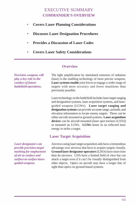
The light amplification by stimulated emission of radiation(laser) is the enabling technology of more precise weapons.Laser systems enable joint forces to engage a wider range oftargets with more accuracy and fewer munitions thanpreviously possible.
Laser technology on the battlefield includes laser target rangingand designation systems, laser acquisition systems, and laser-guided weapons (LGWs). Laser target ranging anddesignation systems can provide accurate range, azimuth, andelevation information to locate enemy targets. These can beeither aircraft-mounted or ground systems. Laser acquisitiondevices can be aircraft-mounted (laser spot trackers [LSTs])or mounted on LGWs. LGWs home in on reflected laserenergy to strike a target.
Aircrews using laser target acquisition aids have a tremendousadvantage over aircrews that have to acquire targets visually.Ground laser designator operators (LDOs) have more timethan do aircrews. LSTs have a limited field of view but canattack a target even if it can’t be visually distinguished fromother objects. Optics on aircraft may have a longer line ofsight than optics on ground-based systems.
Laser Target Acquisition
Precision weapons willplay a key role in theconduct of futurebattlefield operations.
Laser designators canprovide precision targetmarking for employmentof air-to-surface andsurface-to-surface laser-guided weapons.
Covers Laser Planning Considerations
Discusses Laser Designation Procedures
Provides a Discussion of Laser Codes
Covers Laser Safety Considerations
viii
Executive Summary
Joint Pub 3-09.1
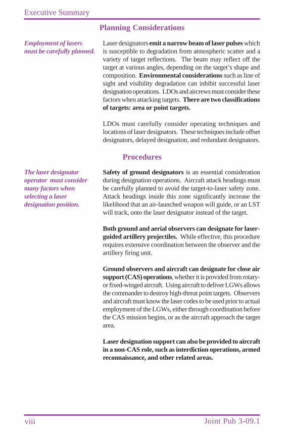
Laser designators emit a narrow beam of laser pulses whichis susceptible to degradation from atmospheric scatter and avariety of target reflections. The beam may reflect off thetarget at various angles, depending on the target’s shape andcomposition. Environmental considerations such as line ofsight and visibility degradation can inhibit successful laserdesignation operations. LDOs and aircrews must consider thesefactors when attacking targets. There are two classificationsof targets: area or point targets.
LDOs must carefully consider operating techniques andlocations of laser designators. These techniques include offsetdesignators, delayed designation, and redundant designators.
Safety of ground designators is an essential considerationduring designation operations. Aircraft attack headings mustbe carefully planned to avoid the target-to-laser safety zone.Attack headings inside this zone significantly increase thelikelihood that an air-launched weapon will guide, or an LSTwill track, onto the laser designator instead of the target.
Both ground and aerial observers can designate for laser-guided artillery projectiles. While effective, this procedurerequires extensive coordination between the observer and theartillery firing unit.
Ground observers and aircraft can designate for close airsupport (CAS) operations, whether it is provided from rotary-or fixed-winged aircraft. Using aircraft to deliver LGWs allowsthe commander to destroy high-threat point targets. Observersand aircraft must know the laser codes to be used prior to actualemployment of the LGWs, either through coordination beforethe CAS mission begins, or as the aircraft approach the targetarea.
Laser designation support can also be provided to aircraftin a non-CAS role, such as interdiction operations, armedreconnaissance, and other related areas.
Procedures
Employment of lasersmust be carefully planned.
The laser designatoroperator must considermany factors whenselecting a laserdesignation position.
Planning Considerations
ix
Executive Summary
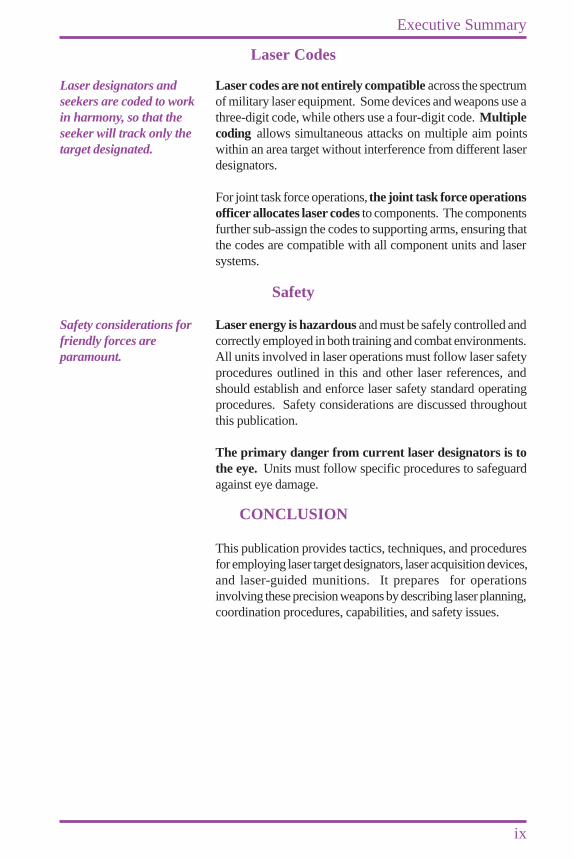
Laser codes are not entirely compatible across the spectrumof military laser equipment. Some devices and weapons use athree-digit code, while others use a four-digit code. Multiplecoding allows simultaneous attacks on multiple aim pointswithin an area target without interference from different laserdesignators.
For joint task force operations, the joint task force operationsofficer allocates laser codes to components. The componentsfurther sub-assign the codes to supporting arms, ensuring thatthe codes are compatible with all component units and lasersystems.
Laser energy is hazardous and must be safely controlled andcorrectly employed in both training and combat environments.All units involved in laser operations must follow laser safetyprocedures outlined in this and other laser references, andshould establish and enforce laser safety standard operatingprocedures. Safety considerations are discussed throughoutthis publication.
The primary danger from current laser designators is tothe eye. Units must follow specific procedures to safeguardagainst eye damage.
This publication provides tactics, techniques, and proceduresfor employing laser target designators, laser acquisition devices,and laser-guided munitions. It prepares for operationsinvolving these precision weapons by describing laser planning,coordination procedures, capabilities, and safety issues.
Laser Codes
Safety
CONCLUSION
Laser designators andseekers are coded to workin harmony, so that theseeker will track only thetarget designated.
Safety considerations forfriendly forces areparamount.

x
Executive Summary
Joint Pub 3-09.1
Intentionally Blank
CHAPTER ICONCEPT
I-1
1. Introduction
a. The Modern Battlefield. Precisionweapons play a significant role inbat t le f ie ld success by providingcommanders with greatly improvedweapon accuracy. This improved accuracyyields higher probability of achieving thedesired end state while lowering theprobability of collateral damage. Thetechnology enabling increased accuracy ofmany of these weapons is the laser.
b. Laser Capabilities. Laser designatorsradiate a narrow beam of pulsed energy.Current tactical lasers operate in the near-infrared wavelength spectrum, which is notvisible to the human eye. When within range,the laser designator can be aimed so the energyprecisely designates a chosen spot on thetarget. Laser target designators (LTDs) marktargets for laser spot trackers (LSTs) and laser-guided weapons (LGWs). Some laser systemscan accurately determine target range andlocation. When coupled with horizontal andvertical scales, they can measure targetazimuth and elevation. LGWs can reduce thenumber of weapons and/or weapon systemsrequired to achieve an objective, because ofincreased accuracy. Based on the threat level
“The key principle underlying Coalition strategy was the need to minimizecasualties and damage, both to the Coalition and to Iraqi civilians. It wasrecognized at the beginning that this campaign would cause someunavoidable hardships for the Iraqi people. It was impossible, for example,to shut down the electric power supply for Iraqi C2 facilities or CW factories,yet leave untouched the electricity supply to the general populace. Coalitiontargeting policy and aircrews made every effort to minimize civilian casualtiesand collateral damage. Because of these restrictive policies, only PGMswere used to destroy key targets in downtown Baghdad in order to avoiddamaging adjacent civilian buildings.”
Conduct of the Persian Gulf War, Final Report to Congress,April 1992, Chapter VI, page 131
and environment, LGWs may provide betterways to attack targets.
c. Laser Procedures on the Battlefield.The battlefield environment can degradeLGW accuracy. All elements employingLGWs must conduct thorough planningand follow established procedures to ensuretheir successful employment.
2. Laser Use on the Battlefield
Laser technology for the battlefield hasdeveloped in many areas, such as laser targetranging and designation systems, laseracquisition systems, and LGWs. Although“infrared (IR) pointers” such as the AN/PAQ-4 and the LPL-30 are technically lasersoperating in the .83 micron range, thediscussion of their use and associated tactics,techniques, and procedures is not covered inthis publication because they are incapable ofguiding LGWs.
For further information on these systems, referto JP 3-09.3, “Joint Tactics, Techniques, andProcedures for Close Air Support (CAS).”
a. Laser Target Ranging andDesignation Systems. Laser target ranging
I-2
Chapter I
Joint Pub 3-09.1
and designation systems can provide accuraterange, azimuth, and elevation information tolocate enemy targets. These systems may varyfrom handheld to aircraft-mounted devicesand perform similar functions with varyingdegrees of accuracy. In combination withglobal positioning system (GPS), lasers canprovide accurate enemy target locations. Inaddition, lasers in combination with GPS canprovide for target area analysis. This analysiscan be used to fire weapons accurately at theenemy, to accurately locate future friendlyobserver locations, and to enable friendlyforces to effectively conduct maneuveroperations as well as command and controltheir forces by accurate identification of terrainreference points.
b. Acquisition Devices. Of the two typesof laser acquisition devices, the first, the LST,is used to aid visual acquisition of the targetto be attacked by another weapon. This typeof laser acquisition device is normallymounted on fixed-wing aircraft or helicopters.The second type of acquisition device is aseeker and guidance kit mounted on LGWswhich guide on coded laser energy.
c. Striking a Target. LGWs home in onreflected laser energy to strike a target. Some
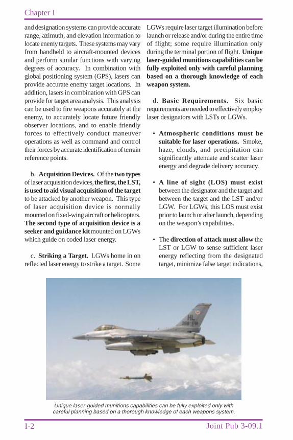
LGWs require laser target illumination beforelaunch or release and/or during the entire timeof flight; some require illumination onlyduring the terminal portion of flight. Uniquelaser-guided munitions capabilities can befully exploited only with careful planningbased on a thorough knowledge of eachweapon system.
d. Basic Requirements. Six basicrequirements are needed to effectively employlaser designators with LSTs or LGWs.
• Atmospheric conditions must besuitable for laser operations. Smoke,haze, clouds, and precipitation cansignificantly attenuate and scatter laserenergy and degrade delivery accuracy.
• A line of sight (LOS) must existbetween the designator and the target andbetween the target and the LST and/orLGW. For LGWs, this LOS must existprior to launch or after launch, dependingon the weapon’s capabilities.
• The direction of attack must allow theLST or LGW to sense sufficient laserenergy reflecting from the designatedtarget, minimize false target indications,
Unique laser-guided munitions capabilities can be fully exploited only withcareful planning based on a thorough knowledge of each weapons system.
I-3
Concept
and preclude the LGW from guiding onthe LTD.
• The laser designator must designatethe target at the correct time and forthe proper duration.
• The pulse repetition frequency (PRF)code of the LTD and LST or LGW mustbe compatible
See Chapter IV, “Laser Codes.”
• The delivery system must release theweapon within the specific weapon’sdelivery envelope.
e. Enemy Use of Laser Countermeasures.During the past few years, the United Statesand its allies have become increasingly relianton laser-guided munitions. Potential USadversaries realize the importance of lasercountermeasures in a conflict with the UnitedStates or its allies. Many of the techniquesfor countering laser energy and sensitiveelectro-optical equipment are commonknowledge throughout much of the world.Potential US adversaries are well-equippedto detect and counter the increasinglysophisticated laser designator and guidancesystems used by the armed forces of Westernnations. Prior to the demise of the WarsawPact, for example, its literature madecontinuous reference to the capabilities ofnatural and manmade obscurants to degradelaser systems, night vision devices, andelectro-optical sensors.
f. Legal Uses of Lasers on theBattlefield. Protocol IV to the CertainConventional Weapons Convention(Protocol on Blinding Laser Weapons)prohibits the use of lasers specificallydesigned to cause permanent blindnessto unenhanced vision. For all othertypes of lasers, such as those used fordetection, targeting, range-finding,communications, and target destruction,
parties to the Protocol have an obligationto “take all feasible precautions to avoidthe incidence of permanent blindness tounenhanced vision.” The United States isnot yet a party to the Protocol on BlindingLaser Weapons, but it has been transmittedby the President to the Senate for adviceand consent to ratification. The “DODPolicy on Blinding Lasers” was revised on17 January 1997, and recognizes thataccidental or incidental eye injuries may occuron the battlefield through the use of lasers fordetection, targeting, range-finding,communications, and target destruction;however, it is Department of Defense (DOD)policy “to strive, through training anddoctrine, to minimize these injuries.”
Safety considerations designed to minimizethese injuries are discussed in Chapter V,“Safety.” Appendix E, “Laser Protocol,”contains the full texts of Protocol IV and thecurrent DOD Policy on Blinding Lasers.
3. Laser Target Acquisition
a. Laser Designator Marking. Laserdesignators can provide precision targetmarking for employment of air-to-surface andsurface-to-surface LGWs. Precise targetmarking with laser designators is directlyrelated to target size and aspect, laser-beamdivergence, designation range, andatmospheric attenuation of the beam.
b. Target Acquisition. With or withoutLSTs, as with all acquisition aids, aircrewsmust always acquire targets visually. Withlimited acquisition time, a fighter or attackaircraft aircrew may not see a small target intime to employ weapons. When targets arewell camouflaged, acquisition is even moredifficult. The aircrew may not be able todistinguish enemy targets from friendly forcesor decoys. Even if the target is large, theaircrew often cannot visually distinguish itfrom natural objects of the same size and coloror IR signature.
I-4
Chapter I
Joint Pub 3-09.1
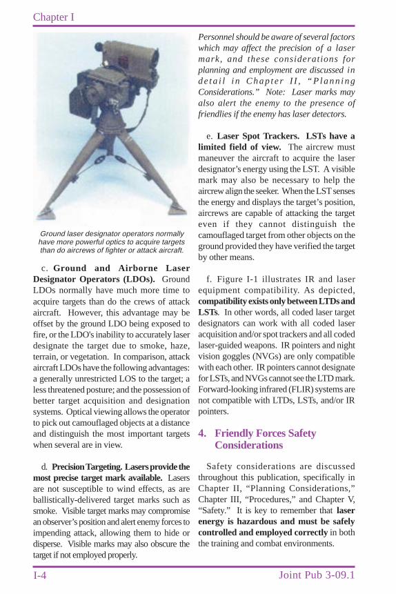
c. Ground and Airborne LaserDesignator Operators (LDOs). GroundLDOs normally have much more time toacquire targets than do the crews of attackaircraft. However, this advantage may beoffset by the ground LDO being exposed tofire, or the LDO's inability to accurately laserdesignate the target due to smoke, haze,terrain, or vegetation. In comparison, attackaircraft LDOs have the following advantages:a generally unrestricted LOS to the target; aless threatened posture; and the possession ofbetter target acquisition and designationsystems. Optical viewing allows the operatorto pick out camouflaged objects at a distanceand distinguish the most important targetswhen several are in view.
d. Precision Targeting. Lasers provide themost precise target mark available. Lasersare not susceptible to wind effects, as areballistically-delivered target marks such assmoke. Visible target marks may compromisean observer’s position and alert enemy forces toimpending attack, allowing them to hide ordisperse. Visible marks may also obscure thetarget if not employed properly.
Personnel should be aware of several factorswhich may affect the precision of a lasermark, and these considerations forplanning and employment are discussed inde ta i l i n Chap te r I I , “P lann ingConsiderations.” Note: Laser marks mayalso alert the enemy to the presence offriendlies if the enemy has laser detectors.
e. Laser Spot Trackers. LSTs have alimited field of view. The aircrew mustmaneuver the aircraft to acquire the laserdesignator’s energy using the LST. A visiblemark may also be necessary to help theaircrew align the seeker. When the LST sensesthe energy and displays the target’s position,aircrews are capable of attacking the targeteven if they cannot distinguish thecamouflaged target from other objects on theground provided they have verified the targetby other means.
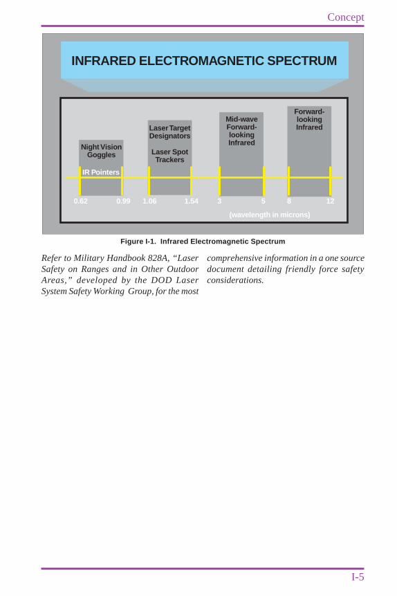
f. Figure I-1 illustrates IR and laserequipment compatibility. As depicted,compatibility exists only between LTDs andLSTs. In other words, all coded laser targetdesignators can work with all coded laseracquisition and/or spot trackers and all codedlaser-guided weapons. IR pointers and nightvision goggles (NVGs) are only compatiblewith each other. IR pointers cannot designatefor LSTs, and NVGs cannot see the LTD mark.Forward-looking infrared (FLIR) systems arenot compatible with LTDs, LSTs, and/or IRpointers.
4. Friendly Forces SafetyConsiderations
Safety considerations are discussedthroughout this publication, specifically inChapter II, “Planning Considerations,”Chapter III, “Procedures,” and Chapter V,“Safety.” It is key to remember that laserenergy is hazardous and must be safelycontrolled and employed correctly in boththe training and combat environments.
Ground laser designator operators normallyhave more powerful optics to acquire targetsthan do aircrews of fighter or attack aircraft.
I-5
Concept
Refer to Military Handbook 828A, “LaserSafety on Ranges and in Other OutdoorAreas,” developed by the DOD LaserSystem Safety Working Group, for the most
INFRARED ELECTROMAGNETIC SPECTRUM
Laser SpotTrackers
0.62 0.99 1.06 1.54 3 5 8 12
LaserTargetDesignators
Forward-lookingInfrared
Mid-waveForward-lookingInfraredNight Vision
Goggles
IR Pointers
(wavelength in microns)
Figure I-1. Infrared Electromagnetic Spectrum
comprehensive information in a one sourcedocument detailing friendly force safetyconsiderations.

I-6
Chapter I
Joint Pub 3-09.1
Intentionally Blank
CHAPTER IIPLANNING CONSIDERATIONS
II-1
1. Laser DesignatorCharacteristics
a. Laser Beam. Laser designators mayemit a narrow, collimated beam of laser pulses.The laser designator possesses several uniquecharacteristics, including beam divergence,which significantly impact laser operations.Another characteristic is the single color(wavelength) of the laser pulses. Laserwavelengths span from the ultraviolet to thevisible to the far IR spectrum. Wavelengthdetermines whether the sensor is visible tothe human eye or specific sensor. Currenttactical laser designators fall in the near IRband and are invisible to the human eye. Thebeam is susceptible to enemy acquisitionthroughout the laser energy wavelength.
b. Beam Divergence and Spot Size. Thelaser spot size is a function of beamdivergence and the distance from the laserdesignator to the target. If a designator hasa beam spread or divergence of 1 milliradian,its spot would have a diameter ofapproximately 1 meter at a distance of 1,000meters in front of the designator. For planningpurposes, spot size should be determined andideally equal to no more than half the targetsurface area.
c. Optics. Ground laser designators haverifle scope-type optics to help aim the laserenergy. The crosshairs allow the laser operatorto select a precise aim point.
d. Atmospheric Scatter. A seeker maydetect scattered radiation that is caused bysuspended matter in the atmosphere. It canoccur even on clear days. This phenomenon
“Victory smiles on those who anticipate the changes in the character of war,not upon those who wait to adapt themselves after the changes occur.”
Giulio Douhet
can cause false seeker lock-on and targetindications within short distances from thelaser exit port. This is also referred to asbackscatter. Safety impacts of this effect arediscussed later in this publication.
Refer also to Military Handbook 828A,“Laser Safety on Ranges and in OtherOutdoor Areas,” for a further discussion.
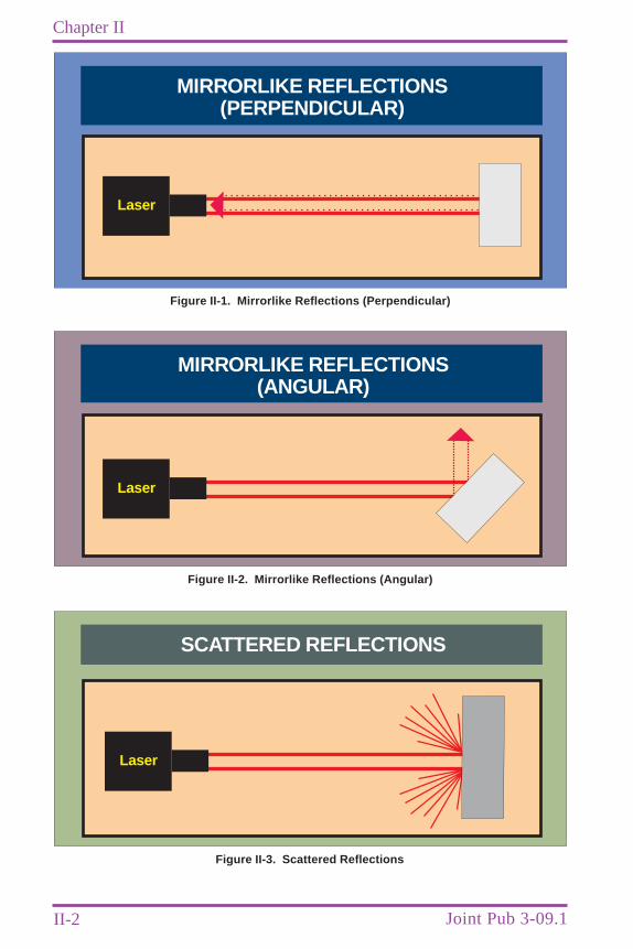
e. Mirrorlike Reflection. Laser energypointed at a mirror will be reflected, andthe beam will remain narrow. If the mirroris perpendicular to the laser beam (FigureII-1), the beam will be reflected directlytoward the laser position. If the mirror is atan angle to the laser beam, the beam will bereflected at an angle equal to the angle of theincident beam (Figure II-2). Any seeker thatis looking for this laser energy would have tobe in the narrow area of reflection. IR energyis reflected in a narrow beam from bare metalas well as from mirrorlike and glass surfaces.
f. Scattered Reflection. If a surface is flatand not shiny, it reflects light and IR energyin a large arc (Figure II-3).
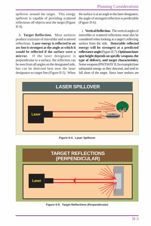
g. Spillover Reflection. Spillover occurswhen the laser spot is larger than the intendedtarget, or when there is unsteady tracking ofthe target from the designator. Overspilloccurs when some of the laser energy goesbeyond the target and impacts an object orterrain behind the intended target. Underspilloccurs when some of the laser energy impactseither terrain or an object short of the intendedtarget. When the target is smaller than thelaser spot or there is unsteady tracking of thetarget from the designator, there is energy
II-2
Chapter II
Joint Pub 3-09.1
MIRRORLIKE REFLECTIONS(PERPENDICULAR)
Laser
Figure II-1. Mirrorlike Reflections (Perpendicular)
MIRRORLIKE REFLECTIONS(ANGULAR)
Laser
Figure II-2. Mirrorlike Reflections (Angular)
SCATTERED REFLECTIONS
Laser
Figure II-3. Scattered Reflections
II-3
Planning Considerations
spillover around the target. This energyspillover is capable of providing scatteredreflections off objects near the target (FigureII-4).
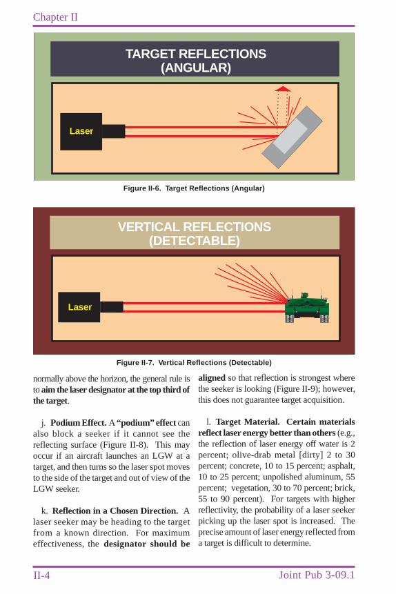
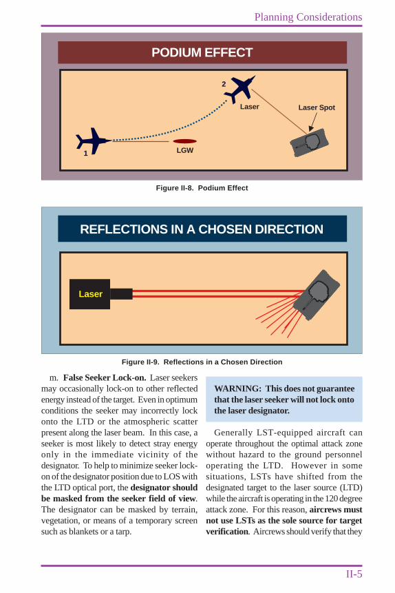
h. Target Reflection. Most surfacesproduce a mixture of mirrorlike and scatteredreflections. Laser energy is reflected in anarc but is strongest at the angle at which itwould be reflected if the surface were amirror. If the laser designator isperpendicular to a surface, the reflection canbe seen from all angles on the designated side,but can be detected best near the laserdesignator-to-target line (Figure II-5). When
the surface is at an angle to the laser designator,the angle of strongest reflection is predictable(Figure II-6).
i. Vertical Reflection. The vertical angles ofmirrorlike or scattered reflections must also beconsidered when looking at a target’s reflectingsurface from the side. Detectable reflectedenergy will be strongest at a predictedreflectance angle (Figure II-7). Optimum laserspot height depends on specific weapons, thetype of delivery, and target characteristics.Some weapons (PAVEWAY II, for example) losesubstantial energy as they descend, and tend tofall short of the target. Since laser seekers are
LASER SPILLOVER
Laser
Figure II-4. Laser Spillover
TARGET REFLECTIONS(PERPENDICULAR)
Laser
Figure II-5. Target Reflections (Perpendicular)
II-4
Chapter II
Joint Pub 3-09.1
normally above the horizon, the general rule isto aim the laser designator at the top third ofthe target.
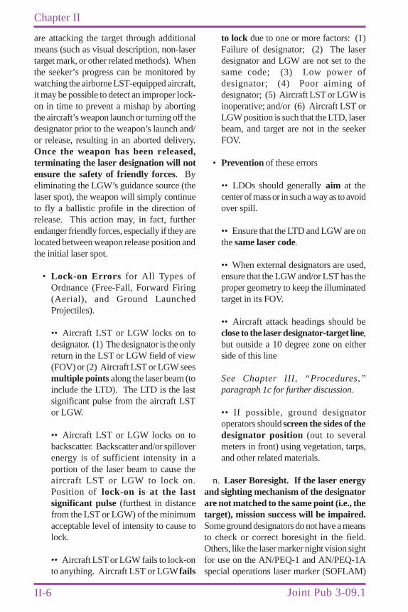
j. Podium Effect. A “podium” effect canalso block a seeker if it cannot see thereflecting surface (Figure II-8). This mayoccur if an aircraft launches an LGW at atarget, and then turns so the laser spot movesto the side of the target and out of view of theLGW seeker.
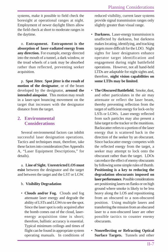
k. Reflection in a Chosen Direction. Alaser seeker may be heading to the targetfrom a known direction. For maximumeffectiveness, the designator should be
aligned so that reflection is strongest wherethe seeker is looking (Figure II-9); however,this does not guarantee target acquisition.
l. Target Material. Certain materialsreflect laser energy better than others (e.g.,the reflection of laser energy off water is 2percent; olive-drab metal [dirty] 2 to 30percent; concrete, 10 to 15 percent; asphalt,10 to 25 percent; unpolished aluminum, 55percent; vegetation, 30 to 70 percent; brick,55 to 90 percent). For targets with higherreflectivity, the probability of a laser seekerpicking up the laser spot is increased. Theprecise amount of laser energy reflected froma target is difficult to determine.
TARGET REFLECTIONS(ANGULAR)
Laser
Figure II-6. Target Reflections (Angular)
VERTICAL REFLECTIONS(DETECTABLE)
Laser
Figure II-7. Vertical Reflections (Detectable)
II-5
Planning Considerations
m. False Seeker Lock-on. Laser seekersmay occasionally lock-on to other reflectedenergy instead of the target. Even in optimumconditions the seeker may incorrectly lockonto the LTD or the atmospheric scatterpresent along the laser beam. In this case, aseeker is most likely to detect stray energyonly in the immediate vicinity of thedesignator. To help to minimize seeker lock-on of the designator position due to LOS withthe LTD optical port, the designator shouldbe masked from the seeker field of view.The designator can be masked by terrain,vegetation, or means of a temporary screensuch as blankets or a tarp.
WARNING: This does not guaranteethat the laser seeker will not lock ontothe laser designator.
Generally LST-equipped aircraft canoperate throughout the optimal attack zonewithout hazard to the ground personneloperating the LTD. However in somesituations, LSTs have shifted from thedesignated target to the laser source (LTD)while the aircraft is operating in the 120 degreeattack zone. For this reason, aircrews mustnot use LSTs as the sole source for targetverification. Aircrews should verify that they
PODIUM EFFECT
Laser
1
2
Laser Spot
LGW
Figure II-8. Podium Effect
REFLECTIONS IN A CHOSEN DIRECTION
Laser
Figure II-9. Reflections in a Chosen Direction
II-6
Chapter II
Joint Pub 3-09.1
are attacking the target through additionalmeans (such as visual description, non-lasertarget mark, or other related methods). Whenthe seeker’s progress can be monitored bywatching the airborne LST-equipped aircraft,it may be possible to detect an improper lock-on in time to prevent a mishap by abortingthe aircraft’s weapon launch or turning off thedesignator prior to the weapon’s launch and/or release, resulting in an aborted delivery.Once the weapon has been released,terminating the laser designation will notensure the safety of friendly forces. Byeliminating the LGW’s guidance source (thelaser spot), the weapon will simply continueto fly a ballistic profile in the direction ofrelease. This action may, in fact, furtherendanger friendly forces, especially if they arelocated between weapon release position andthe initial laser spot.
• Lock-on Errors for All Types ofOrdnance (Free-Fall, Forward Firing(Aerial), and Ground LaunchedProjectiles).
•• Aircraft LST or LGW locks on todesignator. (1) The designator is the onlyreturn in the LST or LGW field of view(FOV) or (2) Aircraft LST or LGW seesmultiple points along the laser beam (toinclude the LTD). The LTD is the lastsignificant pulse from the aircraft LSTor LGW.
•• Aircraft LST or LGW locks on tobackscatter. Backscatter and/or spilloverenergy is of sufficient intensity in aportion of the laser beam to cause theaircraft LST or LGW to lock on.Position of lock-on is at the lastsignificant pulse (furthest in distancefrom the LST or LGW) of the minimumacceptable level of intensity to cause tolock.
•• Aircraft LST or LGW fails to lock-onto anything. Aircraft LST or LGW fails
to lock due to one or more factors: (1)Failure of designator; (2) The laserdesignator and LGW are not set to thesame code; (3) Low power ofdesignator; (4) Poor aiming ofdesignator; (5) Aircraft LST or LGW isinoperative; and/or (6) Aircraft LST orLGW position is such that the LTD, laserbeam, and target are not in the seekerFOV.
• Prevention of these errors
•• LDOs should generally aim at thecenter of mass or in such a way as to avoidover spill.
•• Ensure that the LTD and LGW are onthe same laser code.
•• When external designators are used,ensure that the LGW and/or LST has theproper geometry to keep the illuminatedtarget in its FOV.
•• Aircraft attack headings should beclose to the laser designator-target line,but outside a 10 degree zone on eitherside of this line
See Chapter III, “Procedures,”paragraph 1c for further discussion.
•• If possible, ground designatoroperators should screen the sides of thedesignator position (out to severalmeters in front) using vegetation, tarps,and other related materials.
n. Laser Boresight. If the laser energyand sighting mechanism of the designatorare not matched to the same point (i.e., thetarget), mission success will be impaired.Some ground designators do not have a meansto check or correct boresight in the field.Others, like the laser marker night vision sightfor use on the AN/PEQ-1 and AN/PEQ-1Aspecial operations laser marker (SOFLAM)
II-7
Planning Considerations
systems, make it possible to field check theboresight at operational ranges at night.Employment of newer daylight filters allowthe field check at short to moderate ranges inthe daytime.
o. Entrapment. Entrapment is theabsorption of laser-radiated energy fromany direction. For example, energy directedinto the mouth of a tunnel, a dark window, orthe tread wheels of a tank may be absorbedrather than reflected, preventing seekeracquisition.
p. Spot Jitter. Spot jitter is the result ofmotion of the designator, or of the beamdeveloped by the designator, around theintended aimpoint. This motion may resultin a laser-spot bouncing movement on thetarget that increases with the designatordistance from the target.
2. EnvironmentalConsiderations
Several environmental factors can inhibitsuccessful laser designation operations.Tactics and techniques must, therefore, takethese factors into consideration (See AppendixA, “Laser Equipment Descriptions,” fordetails).
a. Line of Sight. Unrestricted LOS mustexist between the designator and the targetand between the target and the LST or LGW.
b. Visibility Degradation
• Clouds and/or Fog. Clouds and fogattenuate laser energy and degrade theability of LSTs and LGWs to see the spot.Since the laser spot is only acquired afterthe bomb comes out of the cloud, laser-energy acquisition time is short;therefore, ballistic accuracy is essential.Typical minimum ceilings and times offlight can be found in appropriate systemoperating manuals. In conditions of
reduced visibility, current laser systemsprovide signal transmission ranges onlyslightly greater than visual range.
• Darkness. Laser-energy transmission isunaffected by darkness, but darknessmakes locating, identifying, and trackingtargets more difficult for the LDO. Nightsights for laser designators enhanceoperator target identification andengagement during night battlefieldoperations. However, not all hand-heldLTDs are adaptable for night sights and,therefore, night vision capabilities onsome LTDs may be limited.
• The Obscured Battlefield. Smoke, dust,and other particulates in the air mayattenuate or reflect the laser beam,thereby preventing reflection from thetarget of sufficient energy for lock-on byLSTs or LGWs. Laser energy reflectedfrom such particles may also present afalse target to the tracker or the munitions.Backscatter refers to a portion of the laserenergy that is scattered back in thedirection of the seeker by an obscurant.Since backscatter energy competes withthe reflected energy from the target, aseeker may attempt to lock onto theobscurant rather than the target. LDOscan reduce the effect of enemy obscurantsby following some simple rules of thumb.Positioning is a key to reducing thedegradation obscurants imposed onlaser performance. Possible considerationsare positioning lasers on flanks or on highground where smoke is likely to be lessheavy along the LOS and repositioningfrom an obscured to a non-obscuredposition. Using multiple lasers andtransferring the mission from an obscuredlaser to a non-obscured laser are otherpossible tactics to counter enemyobscurants.
• Nonreflecting or Refracting OpticalSurface Targets. Tunnels and other
II-8
Chapter II
Joint Pub 3-09.1
targets that have no capability to reflectlaser energy cannot be directly laserdesignated. Instead, the designator mustbe aimed at a nearby reflecting surfacethat will give satisfactory weaponeffectiveness against the intended target.For example, aiming the laser slightlyabove a tunnel opening would allow aweapon to impact at that critical point.
• Obstructions. Optimum positioningof ground laser designators is essential.Obstructions such as trees, limbs, leaves,and grass between the designator andtarget may prevent a clear, unobstructedview for the use of ground laserdesignators. Jungle operations could thuspreclude the use of ground designatorsand limit the effectiveness of airbornelaser designators (ALDs).
• Temperature Extremes. Extremetemperatures affect batteries, such as theNiCad batteries used for the ground/vehicle laser locator designator(G/VLLD) and modular universal laserequipment (MULE) system, the NiCadsused with the compact laser designator,and those used with the LTD. Forexample, cold-soaked batteries have areduced capability to power lasers.SOFLAM is operable using BA-5590lithium batteries, which are much lesssusceptible to “cold soaked” limitationson run time.
• Solar Saturation. Laser seekerslook for a spot of IR energy thatstands out from the background. Whenthe seeker dome is cracked, pitted, orglazed, the seeker may detect so muchIR energy from the sun that it cannotdiscriminate the laser spot. Thiscondition is most likely to be a problemwhen using low-angle LGWs or LST-equipped aircraft, especially againsttargets above the horizon aftersunrise and before sunset.
• Heat Vapor. When lasing targets duringthe hottest portions of the day, heat vapormay have an adverse effect on the beam.The beam may be refracted in causingdegraded target designation.
3. Seeker Characteristics
a. Seeker Code. Laser seekers look forlaser designator energy on a specific PRFcode. Designators and seekers must worktogether as a team on a specific code becauseseekers will not detect designators set on othercodes.
See Chapter IV, “Laser Codes”.
b. Field of View. All seekers have alimited FOV, and therefore must be orientedso that the target falls within that FOV tosee the laser designator spot.
c. Acquisition Time. To avoid detectionby enemy forces and conserve battery energy,LDOs may limit the amount of time theydesignate a target. Laser seekers andmunitions, therefore, could have a very shorttime to detect the laser spot and guide to thetarget. LGWs require a minimum amount oftime to acquire and track a target. By limitingthe amount of laser designation time, LDOsmay significantly degrade LGW accuracy,resulting in failure to achieve objectives andincreased potential for fratricide.Additionally, LST-equipped aircraft may nothave enough time to acquire the target undershort designation time conditions. Requiredacquisition time is mission-specific, andshould be pre-briefed.
d. Seeker Sensitivity. Different laserguidance and acquisition systems requiredifferent amounts of reflected laser energy tooperate. For example, under ideal conditions,a G/VLLD must be within 5 kilometers (km)of an average stationary target to provideoptimum cannon-launched guided projectiles(CLGPs) (COPPERHEAD) guidance
II-9
Planning Considerations
whereas, under similar conditions, a PAVEPENNY (US Air Force [USAF] pod-contained) LST can acquire a LTD spot at adistance as great as 30 km.
4. Seeker Types
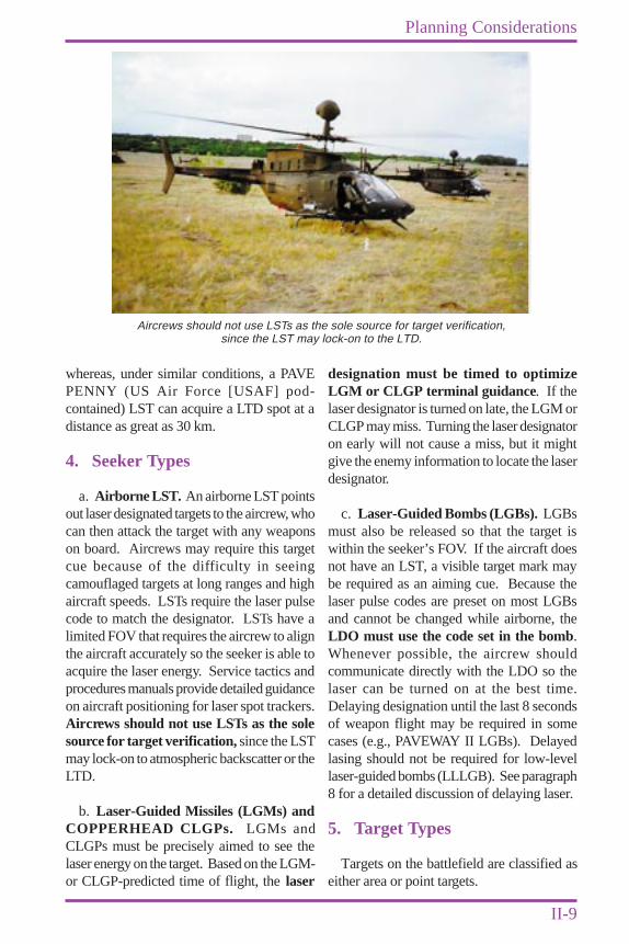
a. Airborne LST. An airborne LST pointsout laser designated targets to the aircrew, whocan then attack the target with any weaponson board. Aircrews may require this targetcue because of the difficulty in seeingcamouflaged targets at long ranges and highaircraft speeds. LSTs require the laser pulsecode to match the designator. LSTs have alimited FOV that requires the aircrew to alignthe aircraft accurately so the seeker is able toacquire the laser energy. Service tactics andprocedures manuals provide detailed guidanceon aircraft positioning for laser spot trackers.Aircrews should not use LSTs as the solesource for target verification, since the LSTmay lock-on to atmospheric backscatter or theLTD.
b. Laser-Guided Missiles (LGMs) andCOPPERHEAD CLGPs. LGMs andCLGPs must be precisely aimed to see thelaser energy on the target. Based on the LGM-or CLGP-predicted time of flight, the laser
designation must be timed to optimizeLGM or CLGP terminal guidance. If thelaser designator is turned on late, the LGM orCLGP may miss. Turning the laser designatoron early will not cause a miss, but it mightgive the enemy information to locate the laserdesignator.
c. Laser-Guided Bombs (LGBs). LGBsmust also be released so that the target iswithin the seeker’s FOV. If the aircraft doesnot have an LST, a visible target mark maybe required as an aiming cue. Because thelaser pulse codes are preset on most LGBsand cannot be changed while airborne, theLDO must use the code set in the bomb.Whenever possible, the aircrew shouldcommunicate directly with the LDO so thelaser can be turned on at the best time.Delaying designation until the last 8 secondsof weapon flight may be required in somecases (e.g., PAVEWAY II LGBs). Delayedlasing should not be required for low-levellaser-guided bombs (LLLGB). See paragraph8 for a detailed discussion of delaying laser.
5. Target Types
Targets on the battlefield are classified aseither area or point targets.
Aircrews should not use LSTs as the sole source for target verification,since the LST may lock-on to the LTD.
II-10
Chapter II
Joint Pub 3-09.1
a. Area Targets. An area target coversan area rather than a single point. Areatargets include infantry formations, fieldartillery positions, assembly areas, motorpools, command posts, aircraft parking ramps,logistics sites, and other targets that are largein size or surface area. They are normallyneutralized with a large volume of firedelivered throughout the target area. Areatargets may be designated for missions usinglaser designators to designate either specifictargets within an area or the general area itself.
b. Point Targets. A point target requiresaccurate placement of munitions in orderto neutralize or destroy it. Tanks, guns,bunkers, surface-to-air missile systems,bridges, communications sites, and watercraftare examples of point targets. Laserdesignators greatly enhance the ability of theobserver or controller to engage and destroyor neutralize point targets.
6. Designator OperatorPositioning Considerations
Laser weapons demand increasedemphasis on basic observer and controllertechniques. Laser designators are normallyemployed by Army fire support teams (FISTs)and combat observation and lasing teams(COLTs), USAF tactical air control parties(TACPs), naval gunfire shore fire controlparties, terminal air control parties, MarineCorps forward observers (FOs) on the ground,certain Army, Navy, Air Force, and MarineCorps aircraft equipped with designators, andspecial operations forces (SOF). To enhanceobserver and LDO team survivability, terrain,cover and concealment, and standoff distancemust be properly used when observing enemyavenues of approach and chokepoints. Thevulnerability of LDOs , especially ALDs,must also be considered when designatingpoint targets like tanks, armored personnelcarriers and guns. When using standoffprocedures for survivability, the LDO mustbe aware that the beam divergence of laser
designators at long standoff ranges couldpreclude effective point-target designation.Wind direction is an important considerationfor LDO positioning for target areas wheremultiple weapon releases are anticipated. LDOsshould position themselves and select order oftarget attacks so that successive targets will notbe obscured by smoke and debris from previousweapons impacts (i.e., the LTD should be setupwind of targets and the targets designated fromthe farthest downwind first to the most upwindlast). Target orientation in relation to the LTDis critical in determining the aircraft attackdirection based on the direction of the reflectedenergy (Refer to Figures II-5 through II-8).
7. Offset Laser Designation
When enemy countermeasures or laser alarmsare likely to affect laser operations, offsetdesignation may be used. When offsetdesignating, the laser designator is aimed at anobject near the target to provide an approximatetarget mark or initial aim point . The LDOshould select an object with good reflection, suchas a building, to enhance acquisition.
a. Offset Procedures. When designatingfor an LST aircraft delivering unguidedweapons, an offset aimpoint may be used.Accurate bearing and distance from the offsetto the target and target description should bepassed to the aircrew.
b. Shift Procedures. When offsetdesignating for an airborne LST, the aircrewmay request the laser to be shifted to the actualtarget for LGW employment. When directedby the aircrew, the designator is smoothlymoved from the offset aim point to the target.
8. Delayed Laser Designationfor LGBs
Delayed lasing is normally associated withPAVEWAY II. This technique is used topreserve LGB energy during low levelreleases to keep the LGB from impacting
II-11
Planning Considerations
short. To avoid missing the target, the laserdesignator must be turned on at a time thatwill permit the bomb to follow an optimumglide path. Lasing too early will cause theweapon to guide on, and turn down towardthe target prematurely, losing valuableenergy, and will cause impacts short of thetarget. The aircrew will know the propermoment to turn the laser on to meet theminimum lase time for proper guidance.Therefore, if required, communicationschannels must be clear so the aircrew cancall for laser activation. In the absence ofpositive two-way communications, targetdesignation time and duration must bepredicted on the basis of a known time-on-target (weapon impact time) and specificLGB laser requirements. The specific LGBand the delivery tactics of the fighter or attackaircraft will dictate the minimum designationtime required to guide the weapon to theintended target. PAVEWAY II LGBs, forexample, when delivered from a low-altitudeloft maneuver, will restrict the designation ofthe target to the final 8 seconds of the weapon’sflight. Delivery of a PAVEWAY II from ahigh-dive delivery (30 to 60 degrees) ormedium altitude level delivery allows foreither continuous or delayed lasing, but in allcases the laser should be on for the final 8seconds of bomb time-of-fall.
For more information on delayed lasing'sassociation with PAVEWAY II, see AppendixA, “Laser Equipment Descriptions,” AnnexT, “Laser-Guided Bombs (PAVEWAY II) (AirForce, Navy, and Marine Corps),” andAppendix D, “LGB And LLLGB DeliveryProfiles.” See Appendix D, “LGB AndLLLGB Delivery Profiles,” for a descriptionof LGB and LLLGB delivery profiles.
9. Delayed Laser Designationfor HELLFIRE
Designation delay can be used inHELLFIRE engagement when the missile isfired in a lock-on after launch (LOAL) mode.
Delayed lasing can be utilized in conjunctionwith a HELLFIRE engagement where thereare low cloud ceilings in the target area.Additionally, delayed lasing will benefit thedesignation unit because the laser will beenergized a less period of time, thereby givingthe enemy less time to react if they have laserwarning receivers. Like all LGW engagements,positive two-way communications greatlyincrease the chances of a successfulengagement when using this technique.
10. Redundant LaserDesignation
Redundant laser designation is atechnique employing two or more laserdesignators in different locations but on thesame code to designate a single target for asingle LGW. Note: This technique is notrecommended. Redundant laser designationmay offer some advantages when attackinghigh-priority targets. The primaryadvantage is that if one designatormalfunctions or is compromised, the seekermay still acquire the reflected energy fromthe other designator and continue guiding tothe target. In the case of moving targets, twodesignators may preclude a guidance failureas a result of temporary blockage. The dangerwith redundant laser designation is that thepresence of two laser designators may causethe LGW to impact where it is not intended.One of the designators may producebackscatter which pulls the LGW away fromthe target. If one of the designators is outsidethe 20-degree safety zone, there is an increasedchance of the LGW guiding on it instead ofthe laser spot. This could also happen if oneof the designators is significantly forward ofthe other. For these reasons, the advantagesof redundant laser designators must beweighed against the disadvantages. The useof this tactic is discouraged, and should notbe routinely employed.
See Chapter III, “Procedures” for moreinformation.

II-12
Chapter II
Joint Pub 3-09.1
11. Laser Systems Descriptions
Appendix A, “Laser Equipment Descriptions,”lists current unclassified laser systems and
munitions, and discusses their generalfunctions and characteristics.
CHAPTER IIIPROCEDURES
III-1
1. General Procedures
a. Laser Designation Position. Inselecting a laser designation position, the LDOmust consider LOS, expected munitionstrajectory, tactical situation, cover andconcealment, weather, and communicationsrequirements. The LDO should selectpositions that are near expected locationsof high priority targets while minimizingrisks to friendly forces. If redundantdesignators are going to be employed, mutualsupport and coordination with maneuverelements should be addressed. The observeror controller team should determine itsposition as accurately as possible; surveysupport should be utilized if available. Theteam can also determine its geographicposition by employing GPS, or by using aMULE or G/VLLD to establish range,azimuth, and vertical angle in relation to aknown location.
See Chapter V, “Safety.”
b. Employment. When employing LSTswith ground laser target designators andLGWs, the following procedures will be used.
• Attack headings and laser-to-target linesare normally pre-coordinated betweenthe LDO and LGW-employing aircrew(or their representative). During closeair support (CAS) operations, terminalcontrollers can recommend an attackcone and/or final attack heading or givedesignator target line (DTL) and allowthe aircrew to determine the correct
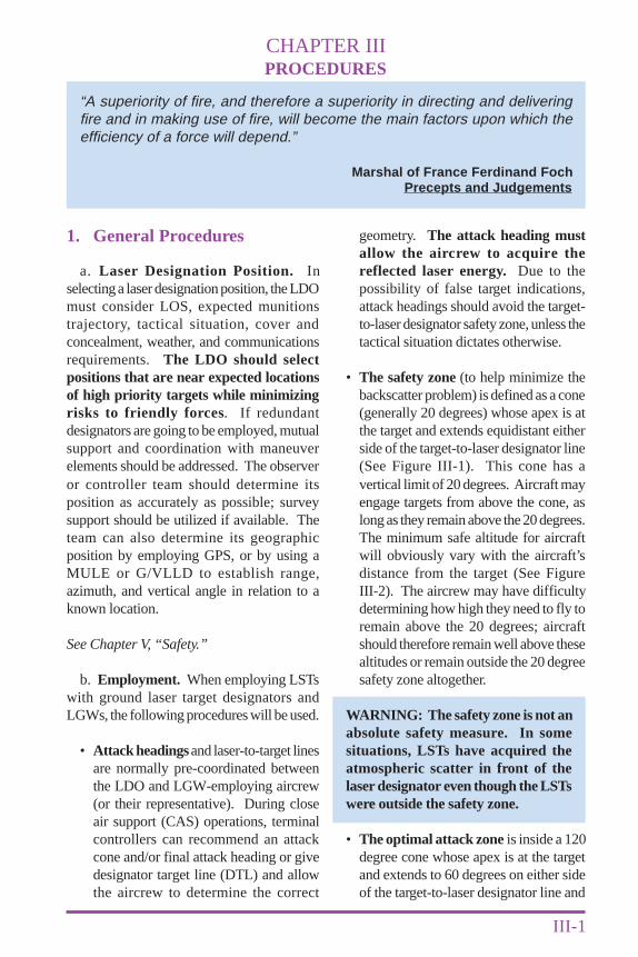
“A superiority of fire, and therefore a superiority in directing and deliveringfire and in making use of fire, will become the main factors upon which theefficiency of a force will depend.”
Marshal of France Ferdinand FochPrecepts and Judgements
geometry. The attack heading mustallow the aircrew to acquire thereflected laser energy. Due to thepossibility of false target indications,attack headings should avoid the target-to-laser designator safety zone, unless thetactical situation dictates otherwise.
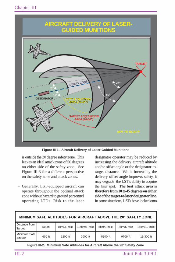
• The safety zone (to help minimize thebackscatter problem) is defined as a cone(generally 20 degrees) whose apex is atthe target and extends equidistant eitherside of the target-to-laser designator line(See Figure III-1). This cone has avertical limit of 20 degrees. Aircraft mayengage targets from above the cone, aslong as they remain above the 20 degrees.The minimum safe altitude for aircraftwill obviously vary with the aircraft’sdistance from the target (See FigureIII-2). The aircrew may have difficultydetermining how high they need to fly toremain above the 20 degrees; aircraftshould therefore remain well above thesealtitudes or remain outside the 20 degreesafety zone altogether.
WARNING: The safety zone is not anabsolute safety measure. In somesituations, LSTs have acquired theatmospheric scatter in front of thelaser designator even though the LSTswere outside the safety zone.
• The optimal attack zone is inside a 120degree cone whose apex is at the targetand extends to 60 degrees on either sideof the target-to-laser designator line and
III-2
Chapter III
Joint Pub 3-09.1
is outside the 20 degree safety zone. Thisleaves an ideal attack zone of 50 degreeson either side of the safety zone. SeeFigure III-3 for a different perspectiveon the safety zone and attack zones.
• Generally, LST-equipped aircraft canoperate throughout the optimal attackzone without hazard to ground personneloperating LTDs. Risk to the laser
designator operator may be reduced byincreasing the delivery aircraft altitudeand/or offset angle or the designator-to-target distance. While increasing thedelivery offset angle improves safety, itmay degrade the LST’s ability to acquirethe laser spot. The best attack area istherefore from 10 to 45 degrees on eitherside of the target-to-laser designator line.In some situations, LSTs have locked onto
AIRCRAFT DELIVERY OF LASER-GUIDED MUNITIONS
SAFEST ACQUISITIONAREA (10-60 )
BEST ACQUISITIONAREA (10-45 )
BEST ACQUISITIONAREA (10-45 )
NOTTO SCALE
TARGET
DESIGNATOROO
OO
10O
10O
SAFETY ZONE
60O
45O
Figure III-1. Aircraft Delivery of Laser-Guided Munitions
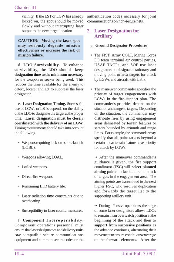
MINIMUM SAFE ALTITUDES FOR AIRCRAFT ABOVE THE 20° SAFETY ZONE
Distance fromTarget 500m 1km/.6 mile 1.6km/1 mile 5km/3 mile 8km/5 mile 16km/10 mile
Minimum SafeAltitude 600 ft 1200 ft 2000 ft 5800 ft 9700 ft 19,300 ft
Figure III-2. Minimum Safe Altitudes for Aircraft Above the 20º Safety Zone
III-3
Procedures
the laser source while operating in the 120degree attack zone.
CAUTION: For this reason, aircrewsshould not use LSTs as the sole sourcefor target verification.
Aircrews should verify that they areattacking the correct target through additionalmeans (such as visual description, terrainfeatures, non-laser target marks). Wheneverpossible, planned attacks should avoidplacing the designator in the FOV of theLST or LGW .
c. Terrain and Target Concealment
• If the LDO suspects that the target maybe partially masked from the view of
the incoming laser weapon, the LDOshould aim the laser at a point on thetarget believed to be within LOS of theseeker. If the target is well concealed,the laser spot may be aimed at someoverhead or nearby object. However, thismethod is not preferred and should beused only when the situation demandsan immediate attack on the target.
• If a designated mobile target moves outof the view of the LDO, it may still bepossible to salvage the attack. A pointnear the target may be designated untilthe target again comes into view or untildesignation responsibility can be passedto another operator who has the target insight. It is also possible to move the spotto another target in the immediate
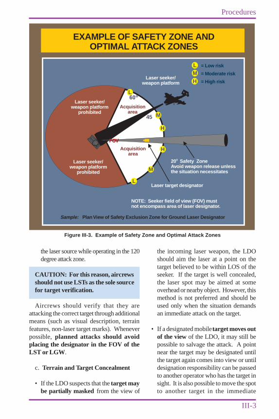
EXAMPLE OF SAFETY ZONE ANDOPTIMAL ATTACK ZONES
Acquisitionarea
Acquisitionarea
Laser target designator
NOTE: Seeker field of view (FOV) mustnot encompass area of laser designator.
Sample: Plan View of Safety Exclusion Zone for Ground Laser Designator
Laser seeker/weapon platform
Laser seeker/weapon platform
prohibited
Laser seeker/weapon platform
prohibited
L60
o
45
L
M
M
H
= Low risk
= Moderate risk
= High risk
LMH
H
FOVFOV
20 Safety ZoneAvoid weapon release unlessthe situation necessitates
0
Figure III-3. Example of Safety Zone and Optimal Attack Zones
III-4
Chapter III
Joint Pub 3-09.1
vicinity. If the LST or LGW has alreadylocked on, the spot should be movedslowly and without interrupting laseroutput to the new target location.
CAUTION: Moving the laser spotmay seriously degrade missioneffectiveness or increase the risk ofmission failure.
d. LDO Survivability. To enhancesurvivability, the LDO should keepdesignation time to the minimum necessaryfor the weapon or seeker being used. Thisreduces the time available for the enemy todetect, locate, and act to suppress the laserdesignator.
e. Laser Designation Timing. Successfuluse of LGWs or LSTs depends on the abilityof the LDO to designate the target at the propertime. Laser designation must be closelycoordinated with the delivery of an LGW.Timing requirements should take into accountthe following.
• Weapons requiring lock-on before launch(LOBL).
• Weapons allowing LOAL.
• Lofted weapons.
• Direct-fire weapons.
• Remaining LTD battery life.
• Laser radiation time constraints due tooverheating.
• Susceptibility to laser countermeasures.
f. Component I n t e ro p e rab i l i ty .Component operations personnel mustensure that laser designators and delivery unitshave compatible secure communicationsequipment and common secure codes or the
authentication codes necessary for jointcommunications on non-secure nets.
2. Laser Designation forArtillery
a. Ground Designator Procedures
• The FIST, Army COLT, Marine CorpsFO team terminal air control parties,USAF TACPs, and SOF use laserdesignators to designate stationary andmoving point or area targets for attackby LGWs and aircraft with LSTs.
• The maneuver commander specifies thepriority of target engagements withLGWs in the fire-support plan. Thecommander’s priorities depend on thesituation and range to targets. Dependingon the situation, the commander maydistribute fires by using engagementareas delineated by terrain features orsectors bounded by azimuth and rangelimits. For example, the commander mayspecify that all point targets beyond acertain linear terrain feature have priorityfor attack by LGWs.
•• After the maneuver commander’sguidance is given, the fire supportcoordinator (FSC) will select plannedaiming points to facilitate rapid attackof targets in the engagement area. Theaiming points are transmitted to the nexthigher FSC, who resolves duplicationand forwards the target list to thesupporting artillery unit.
•• During offensive operations, the rangeof some laser designators allows LDOsto remain in an overwatch position at thebeginning of the attack and then tosupport from successive positions asthe advance continues, alternating theirmovement to ensure continuous coverageof the forward elements. After the
III-5
Procedures
objective is taken and consolidation isunder way, the laser designator is rapidlyrepositioned to designate retreating pointtargets and respond to possiblecounterattacks.
•• During defensive operations, the FISTcoordinates the location of the laserdesignators with the companycommander.
b. Airborne Laser DesignatorProcedures. The greater mobility of ALDsenables the LDO to more easily acquire targetsand maintain a constant LOS with them.Aerial observers use the same calls for fire asground observers. They obtain a gun-targetline from the fire direction center (FDC) andposition themselves near the gun-target lineto increase the probability of targetengagement by CLGPs. In a heavy enemyair defense situation, the ALD should standoff as far as possible; in these situations, theuse of suppression of enemy air defenses(SEAD) missions should be planned. Allother procedures remain the same as thoseused for ground designators.
c. CLGP and/or “COPPERHEAD”Employment
• Optimum use of COPPERHEAD isagainst multiple targets in large targetarrays outside the range of maneuverdirect fire weapon systems(approximately 3,000 meters).COPPERHEAD targets can be engagedas either planned targets or targets ofopportunity. Planned targets arepreferred due to the complexity oftechnical fire direction computationsand ammunition handling procedures inthe firing units. Most often, the target ofopportunity technique is used only duringoffensive operations.
• Targets of Opportunity. Attacking astationary target of opportunity requires
the observer to determine the targetlocation and transmit a call for fire.Attacking a moving target of opportunityis more complicated because it requiresthe observer to predict where the targetwill be (intercept point) by estimating thetarget speed and direction of movementand comparing it to the firing unit missionprocessing time. The observer uses thisinformation to determine the proper time(trigger point) to initiate a call for fire sothat the round impacts at the targetlocation.
• Planned Targets. Planned targets aredeveloped as a result of the fire supportplanning process. This permits optimalobserver positioning and allows theobserver to pre-determine intercept,trigger points, and COPPERHEADengagement areas utilizing footprinttemplates.
• E f f e c t i v e e m p l o y m e n t o fCOPPERHEAD is enhanced bytechniques used by the fire support officer(FSO) to position the COLT, FIST, or FObefore target engagement and byobserver techniques at the observationpost. Steps involved in optimizingt h e po ten t ia l emp loyment o fCOPPERHEAD are as follows.
•• Position the observer to mosteffectively accomplish the commander’starget attack guidance.
•• Ensure that a target engagement angleT (the angle between the gun-target lineand the observer-target line) is no greaterthan 800 mils, as this would adverselyaffect COPPERHEAD targeting.
•• Position the observer within the rangecapabilities of the laser designator. Themaximum effective distance for the G/VLLD is 3,000 meters for moving targetsand 5,000 meters for stationary targets.
III-6
Chapter III
Joint Pub 3-09.1
The maximum effective distance for theMULE is 2,000 meters for movingtargets and 3,500 meters for stationarytargets.
•• Construct a visibility diagram from theselected position when it is occupied.
•• Employ the appropriate COPPERHEADfootprint. Footprints are roughly oval inshape and form around the targetlocation. The optimum limit ofengagement is within the boundaries ofthe footprint. Although COPPERHEADcan maneuver outside the limits of thefootprint, the greatest chance of hittingthe target is when it is at or near thelocation sent to the FDC by the observer.The outer boundary of the footprintrepresents a 50-percent probability of atarget-hit; the location sent to the FDChas a target-hit probability substantiallyhigher than 50 percent. The size andshape of the footprint are affected bycloud height, the range from the firingunit to the target, visibility, and the angleof fire (high or low). Footprint templateshave been developed to accuratelyportray the engagement area of eachadjusting point. Each footprint templatehas the oval shaped footprint (to 1:50,000scale) based on the firing unit range tothe target and cloud height, and is markedwith a letter identification code.
•• Designate the target continuouslyduring the last 13 seconds of theCOPPERHEAD’s flight.
NOTE: For a detailed explanation ofObserver-FDC COPPERHEADprocedures see Appendix B,“Procedures Guide.”
•• If the observer does not acknowledgethe “LASER ON” call, the FDC willcontinue to transmit “LASER ON” untilrounds impact.
3. Laser Designation for CAS
This section discusses procedures for usinglaser designators for CAS missions andincludes: (1) Adding laser designationprocedures to the CAS briefing and aircrewreporting procedures; (2) Establishing ameans of communication between the forwardair controller (FAC) and FO to coordinate laserdesignation of targets when the FAC is notcollocated with the laser designator; and (3)Establishing standard terminology for laser-related activities.
For a detailed explanation of CASemployment procedures and tactics, refer toJP 3-09.3, “Joint Tactics, Techniques, andProcedures for Close Air Support (CAS),” andService-specific CAS publications.
a. Target Acquisition Considerations
• Using laser designators for CAS canprovide a fast and accurate means ofmarking targets for both LGWs andLST-equipped aircraft. Using targetcoordinates, smoke, and illuminatingflares complements laser designatortarget-marking and improves the chancesfor successful first pass target acquisition.Without cueing, aircraft may be pointedtoo far away from the target to acquirethe laser spot. Therefore, when thetactical situation allows, supplementalmarking is recommended to avoidlosing sorties or having to re-attack. Careshould be taken to avoid obscuring thetarget with the secondary mark.
• Aircraft equipped with an LST are ableto detect reflected laser energy. Theseaircraft include: A/OA-1O, non-radarequipped AV-8B, selected F/A-18C/D(when LST is externally mounted as astore), AH-64, MH-60L, and AH-6aircraft. LST-equipped aircraft can usedetected laser energy to acquire andattack both area and point targets. The
III-7
Procedures
extreme accuracy of laser targetdesignation assists fighter and attackaircraft crews in positively identifying thecorrect target and significantly reduces thepossibility of an aircrew misidentifyingfriendly positions as the target.
• LST-equipped aircraft should notify theterminal controller of their capability.The terminal controller should then passthe laser code to the attacking aircrew.In the case of LGBs, the aircrew willinform the terminal controller of theweapon’s laser code because the LGBcode must be set prior to takeoff. If aforward air controller (airborne)(FAC[A]) is being utilized, coordinationwill be made between the groundcontroller, FAC(A), and the attackingaircrew. Coordination will be critical ifthe laser designator is not physicallylocated with the terminal controller. Acomplex example would be a non-lasercapable FAC(A) supporting a non-lasercapable TACP, who is coordinating withthe FO who has a designator. TheFAC(A) will subsequently pass the codeto the TACP, FIST, and/or FO. TheMarine Corps FAC will pass the code tothe FO only if the FO is tasked todesignate the target.
b. Standoff LGW Delivery
• Target acquisition is usually followed bythe delivery of LGWs. Some LGWs,such as laser MAVERICK, and LLLGBand/or PAVEWAY III, can be released atstandoff ranges that may reduce thedelivery aircraft’s exposure to enemy airdefense systems and increase aircraftsurvivability.
• Once released, the weapon homes in onreflected laser energy.
• Like any air delivered weapon system,the maneuver commander must fully
understand and accept the consequencesof a possible failure of the weapon toproperly guide to the target. The finaldecision to release standoff LGWsfrom behind friendly lines in a CASenvironment rests with the maneuvercommander.
c. Concept of Employment
• Tactical Air Control Party. The TACPis the Marine Corps or Air Force tacticalair control agency located with thesupported ground unit. Its functions areproviding air liaison, advising on the useof air assets, and coordinating andcontrolling CAS missions to support theground commander’s scheme ofmaneuver. Three Marine naval aviatorsor naval flight officers are typicallyassigned to each Marine Corps TACP:one serves as the battalion air officer whoworks in the battalion’s fire supportcoordination center (FSCC), and theother two are FACs and usually deploywith the forward rifle companies. TheAir Force TACP at battalion levelnormally consists of one air liaisonofficer (ALO) and two enlisted tacticalair command and control specialists, atleast one of whom is an enlisted terminalattack controller (ETAC). TACPsassigned to light battalions may have upto five controllers. The ALO and ETACsprovide terminal CAS control.
• FIST and FO Procedures for CAS.When possible, the Air Force FACshould be located with the FIST, and theFIST should place a radio close to theLDO (Marine Corps FACs may or maynot be collocated with their FOs).Placing a radio close to the LDO willminimize the need to relay laser callsbetween the pilot and the FIST. At times,the Air Force FAC will not be with theFIST and may not be able to see thetarget. The FAC will control the aircraft
III-8
Chapter III
Joint Pub 3-09.1
and coordinate laser designation with theFIST. When the FAC and FIST are nottogether, aircrews may make laser callsdirectly to the FIST on a frequencyassigned by the FAC in the remarkssection of the CAS briefing (inaccordance with [IAW] Joint Pub 3-09.3,“Joint Tactics, Techniques, andProcedures for Close Air Support[CAS]”). In situations where the MarineCorps FAC is not in an optimum positionto designate the target, the FAC maycontrol the aircraft with the FO actuallydesignating the target. The Marine CorpsFAC and FO can communicate andcoordinate using the TACP local net;however, prior coordination is required.
• FAC Not Present. There may besituations where the FAC is not present,or cannot see the battlefield (e.g., securityoperations in front of friendly positions,night operations). In these situations, aqualified fixed- or rotary-wing FAC(A)may direct the terminal control of CASin coordination with the TACP. In theabsence of a TACP or airborne FAC, theFIST can also provide emergencycontrol of CAS. However, under thesecircumstances, the requesting landcommander assumes responsibility forthe results of the attack.
• Special Operations Terminal AttackController (SOTAC). SOTACs arequalified members of Air Force specialoperations command special tacticsteams and are certified to conductterminal attack control and laserdesignation operations unilaterally orwith other US or coalition units insupport of SOF missions. The joint forcespecial operations componentcommander will track locations,frequencies, and call signs of deployedSOTACs and relay this information tothe special operations liaison element in
the joint force air componentcommander’s joint air operations center.
• Other Special Operations Forces.Other SOF units, primarily Army specialforces detachments, Ranger units, andNavy sea-air-land teams (SEALs), aretrained and equipped to conductterminal control operations under theSOF core mission of direct action. Thiscould be for CAS or laser designation foran interdiction attack of high-payofftargets deep in enemy territory. SOFforces can emplace remote command-activated designators which can beactivated when needed.
• Marine Expeditionary Unit (SpecialOperations Capable) (MEU[SOC]).MEU(SOC)s are the Marine Corpsprimary forward-deployed Marine air-ground task force (MAGTF). TheMEU(SOC)s numerous capabilitiesinclude the ability to conduct laserdesignation for an attack against high-payoff targets. The laser designationcapability is resident in bothMEU(SOC)’s night targeting systemequipped AH-1W Cobra and the directaction (DA) platoon of the forcereconnaissance detachment. The DAplatoon is capable of surface, subsurface,and parachute insert. As such it candesignate targets for MAGTF, joint,coalition, or allied aircraft whileoperating deep within enemy territory.
d. FAC Procedures
• FAC Responsibilities. The FAC shouldexpect to use LST-equipped aircraft andaircraft with LGWs. The FAC shouldplan to use laser target designation to helpLST-equipped aircraft identify the targetquickly and accurately. Early planningby the FAC is required to ensure thatthe FIST or FO is ready for laser
III-9
Procedures
operations when the fighter or attackaircraft first contacts the FAC. Thus, theFAC must have a thorough workingknowledge of the capabilities of LST-equipped aircraft and of aircraft-delivered LGWs. When conductingCAS with lasers, always strive forsimple communications. Goodpreplanning, accurate target location, andreliable communications are essential.Critical targets must be identified to theFAC (The joint CAS briefing format islisted in Appendix C, “CAS BriefingForm [9-Line]”).
• Laser Designation Coordination
•• The laser designator may be turnedon for target acquisition, targetidentification, or employment of LGWs.The following communication sequencewill be employed: (1) TEN SECONDS(time until “LASER ON” call expected);(2) LASER ON; (3) SHIFT (ifrequired); (4) SPOT; and (5)TERMINATE.
NOTE: The “10 SECONDS” callmeans the aircrew wants the laser onin approximately 10 seconds. The FACrelays the call to the LDO. The“LASER ON” call requires the FAC(or FIST) to ensure that the LDOdesignates the target immediately. Thesituation will determine whether theattacking aircrew or elements of thefriendly ground forces will make thesecalls.
•• The FAC (or Army FIST) shouldacknowledge the “LASER ON” call.The FAC may elect to turn the laser on10 seconds after the “10 SECONDS” callwithout hearing the “LASER ON” callif problems are expected.
•• Offset designation procedures may beused in a laser countermeasures
environment. Following the “LASERON” call, a “SHIFT” call will be usedto shift laser energy from the offsetposition next to the target onto thetarget itself. The “SHIFT” call, whenused, must be pre-briefed to replace the“SPOT” call.
•• The aircrew calls “SPOT” whenacquiring the laser spot, confirming tothe FAC and the wingman that the aircraftor weapon laser seeker has identified asource of laser energy which may be thedesignated target.
•• For multiple aircraft in the sameattack, “SHIFT” calls may be used afterthe lead aircraft calls “SPOT” to directthe LDO to shift the laser to the nextaircraft’s target. This call is usually usedfor target acquisition in conjunction withweapons not requiring terminal laserguidance.
•• The last call in the sequence is“TERMINATE.” The pilot makes thiscall to turn the laser off.
• Turning the Laser Off. Minimizing thetime a laser is on is important in a lasercountermeasures environment and whenemploying battery operated laserdesignators. Careful planning must beconducted when aircraft are attackingin line or wedge formations to ensurethat the lead aircraft does not terminatethe laser before the wingman’s lock-on.When in trail, each aircraft may want tomake separate laser on and terminatecalls, depending on their separation. Thelaser designator operator will turn thedesignator off:
•• When the “TERMINATE” call isheard;
•• When the weapon hits the target(s);or
III-10
Chapter III
Joint Pub 3-09.1
•• Target coordinates;
•• Target elevation;
•• Time-on-target LASER ON time andLASER OFF time;
•• Laser code and DTL;
•• Target description;
•• Friendly location(s); and
•• Threat.
e. LDO Procedures. The LDO must beextremely responsive to the aircrew’s“LASER ON” call. Unless using offsetdesignation procedures, the LDO mustdesignate only one target and not move orsearch while the designator is on and aircraftare in the area. Following the FAC’sinstructions explicitly will help preventconfusion and miscoordination.
f. LST-Equipped Aircraft-AidedDelivery of Non-Laser-Guided Weapons.With an LST-equipped aircraft, the aircrewcan use the laser spot as an aid to visuallyacquire the target. Delivering non-LGWs onwell-camouflaged targets may requirecontinuous designation to accurately deliverstrafing or ballistic ordnance.
CAUTION: Aircrews should not useLSTs as the sole source for targetidentification.
g. LGB and PAVEWAY II (and III). Thelaser code is set on the ground prior to launchand cannot be changed by the aircrew in theair. The FAC will pass the LGB code to theLDO.
• Run-In. When planning the mission, theFAC must carefully select the run-in
•• After 20 seconds (or longer, ifrequested) to conserve the laser’s battery.
• Laser Countermeasures Environment.When operating in a high lasercountermeasures environment, the FACmay have to coordinate laserdesignation based on timing ratherthan radio calls. In such a case, the CASbriefing includes the time to LASER ON.The FAC would say, for example,“LASER ON IN 4 MINUTES READY,READY, HACK.” Standardizedcommunications calls include: “LASERON AT 35” or “LASER ON IN 5+00,HACK” (use of the atomic clock methodis preferred). Aircrew shouldacknowledge the “HACK.” As required,FAC will give the LDO a similar briefing.The LDO will designate at the specifiedtime and continue designating asrequired.
• If No Spot Is Acquired. If no spot isacquired, the FAC should refer to back-up or CAS talk-on procedures. Postordnance delivery procedures followstandard CAS practices. If a subsequentattack is conducted, the FAC shouldverify that the aircrew knows the locationof the target and that the LDO and theLGW and/or LST are set on the samelaser code. If the weapons do not guide,the FAC should inform the aircrew. Re-attacks should not be attempted in a highthreat environment.
• Emission Control Procedures. Somemissions may require that laser targetdesignation be accomplished in a radiosilence environment. For these missions,there will be an established time-over-target window when the laser designatorwill be turned on. Aircrews need, at aminimum, the following informationprior to the mission:
III-11
Procedures
heading to ensure first pass delivery andsafety for friendly ground positions.
• LGB Release. LGBs must be releasedwithin the weapon’s delivery envelope.For best results, the aircrew must seethe designated target. In some cases,the attacking aircraft may havesufficiently accurate bombing referencesfrom onboard navigation cues to permitreleasing the bomb without the aircrewseeing the target. Because of the risk tofriendly ground forces, the FAC shouldavoid loft attacks with weapons releasebehind friendly positions.
• Laser Call Coordination. Timelycoordination of “LASER ON” and“TERMINATE” calls are essential toeffective LGB delivery, especially in aCAS environment. Designating the targettoo early may cause LGBs to guide toosoon and hit well short of the target.
• Standoff Delivery of LGBs. Deliveryof LGBs near friendly forces is a riskyventure and requires extremely closecoordination between the deliveryaircraft and FAC, attack helicopter, andLDO. Because of the inherent risk tofriendly ground troops, the groundcommander requesting the support mustauthorize LGB standoff deliveries. If theLGB guidance system detects reflectedlaser energy from the target designatortoo soon after release, it tends to pull theLGW down below its required trajectoryand the bomb will hit well short of thetarget. For this type of attack, it is criticalto delay lasing, i.e., begin designatingthe target only during the last part ofthe bomb’s flight. The aircrew must call“LASER ON” based upon itscomputation of the bomb’s time of flightto ensure safe and accurate terminalguidance. The aircrew must knowexactly where the target is and make avery accurate delivery and release of the
weapon. If the bomb is released in a highangle loft, continuous lasing is possiblebecause the seeker won’t see thedesignator until it apexes and starts down.Again, only the ground commandercan authorize a loft delivery frombehind friendly lines. The aircrew issolely responsible for delivering aweapon within guidance parameters.Weapons delivered for optimum laserprofiles are not necessarily optimized forunguided or ballistic trajectories that willpermit target destruction without laserguidance.
See Appendix D, “LGB And LLLGBDelivery Profiles,” for examples of LGBdelivery profiles.
h. LLLGB/PAVEWAY III Delivery. TheLLLGB/PAVEWAY III is an advanced LGBwith a standoff delivery capability from allaltitudes. This bomb has a wider FOV thanthe PAVEWAY II, is not as delivery-parametersensitive, and is not negatively affected byearly laser designation. In fact, continuouslasing is best since it results in the best bombflight profile and provides the most time forlateral and/or wind corrections. After a properdelivery, the LLLGB will maintain level flightwhile looking for reflected laser energy. Ifthe LLLGB does not detect reflected laserenergy, it will maintain level flight to continuebeyond the location of the designated target.Approach angles should be planned so that along hit will not result in fratricide. Groundcommander and aircrew responsibilitiesremain unchanged.
i. Laser-Guided Missile Delivery. FACprocedures for delivering LGMs likeMAVERICK (AGM-65E) and HELLFIRE(AGM-114) are similar to those for deliveringLGBs. The FAC’s role in planning themission, briefing and getting the aircrew ontothe correct run-in heading, and commencingillumination of the target remains the same.However, one major difference exists — the
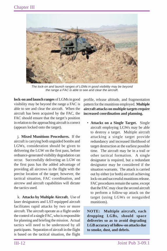
III-12
Chapter III
Joint Pub 3-09.1
profile, release altitude, and fragmentationpattern for the munitions employed. Multipleaircraft attacks on multiple targets requireincreased coordination and planning.
• Attacks on a Single Target. Singleaircraft employing LGWs may be ableto destroy a target. Multiple aircraftattacking a single target provideredundancy and increased likelihood oftarget destruction at the earliest possibletime. The aircraft may be in a trail orother tactical formation. A singledesignator is required, but a redundantdesignator may be considered if thesituation warrants. The attack is carriedout by either (or both) aircraft achievinglock-on and successful munitions release.FAC procedures remain the same, exceptthat the FAC may clear the second aircraftto perform a follow-up attack on thetarget (using LGWs or nonguidedmunitions).
NOTE: Multiple aircraft, eachdropping LGBs, should spacedeliveries so as to avoid degradingLGB accuracy of follow-on attacks dueto smoke, dust, and debris.
lock-on and launch ranges of LGMs in goodvisibility may be beyond the range a FAC isable to see and clear the aircraft. When theaircraft has been acquired by the FAC, theFAC should ensure that the target’s positionin relation to the approaching aircraft is correct(appears locked onto the target).
j. Mixed Munitions Procedures. If theaircraft is carrying both unguided bombs andLGWs, consideration should be given todelivering the LGW on the first pass, beforeordnance-generated visibility degradation canoccur. Successfully delivering an LGW onthe first pass has the added advantage ofproviding all aircrews in the flight with theprecise location of the target; however, thetactical situation, FAC coordination, andaircrew and aircraft capabilities will dictatethe tactics used.
k. Attacks by Multiple Aircraft. Use oflaser designators and LST-equipped aircraftfacilitates rapid attacks by two or moreaircraft. The aircraft operate as a flight underthe control of a single FAC, who is responsiblefor planning and briefing the mission. Actualtactics will need to be understood by allparticipants. Separation of aircraft in the flightis based on the tactical situation, the flight
The lock-on and launch ranges of LGMs in good visibility may be beyondthe range a FAC is able to see and clear the aircraft.
III-13
Procedures
• Attacks on Multiple Targets
•• Simultaneous tactical formationattacks on multiple targets may requireas many laser designators as there areaircraft. The laser equipment must beset on different codes to prevent all theaircraft in the formation from lockingon the same target. If the TACP or FISThas only one laser designator or all targetsare not visible from their position,coordination with adjacent unit laser-designator operators will be required.Communications must be established andauthority obtained to use the adjacent unitlaser designators. Communicationsconnectivity is done before the aircrewis briefed. The FAC controlling the attackgives the command to each LDO to begindesignating targets.
•• Sequential target attacks (aircraft intrail) can be accomplished by designatingwith a single laser designator or multiplelaser designators. If all LGWs have thesame laser code, timing between LGWreleases must be sufficient to deconflictthe attacks on separate aim points (i.e.,the second set of LGWs should not bereleased until the laser designator hasmoved the laser spot to the new aimpoint). If the LGWs have differentcodes, the time between attacks mustbe sufficient for the designator operatorto change codes and move the laser spotto the follow-on aim point. It is better touse separate laser designators on differentcodes for each aim point; however, morecoordination is required. Using multipledesignators has the added advantageof reducing the length of time anysingle laser is on and exposed to enemycounteraction. As with the tacticalformation attack, the mission is planned,briefed, and controlled by a single FAC.The FAC also controls the LDOs.
See Appendix B, “Procedures Guide,”for a discussion of ground and airbornedesignation procedures for CAS.
l. Night and/or Low Light Operations
• General. Because of target acquisitionproblems, CAS at night is more difficultfor both the FAC and the attackingaircrew. The ability to use visual cues isdetermined by the natural light,availability and correct placement ofartificial illumination, and whether or notthe battle area is marked by muzzleflashes, tracers, explosions, and fires.Sighting-in the laser designator andmaintaining the spot on the target isdifficult, particularly if the target ismoving. Flare effects, ordnance flashes,and the lack of a visible horizon also placeaircrew at risk of becoming spatiallydisoriented. Coordination and properseparation between individual aircraft inthe flight are more difficult at night andgenerally result in a slower pace ofoperations. Unaided visual sighting of anaircraft without lights at night is virtuallyimpossible. CAS procedures and releaseapproval for night operations will bedifferent from daytime conditions.
• Laser-Aided Night Attacks. Using alaser designator and LST-equippedaircraft greatly reduces the aircrew’starget acquisition problem if it is allowedto deliver the munitions on the spotappearing on the heads-up display(HUD). Without corroborating sensorssuch as FLIR and NVGs, this procedureshould not be employed where safety offriendly troops is of primary concern, i.e.,CAS. When aircrew are employingFLIR and NVGs, however, they are ableto “visually” acquire and confirm theselected target after receiving the laserspot from an LST. Once the aircrew has
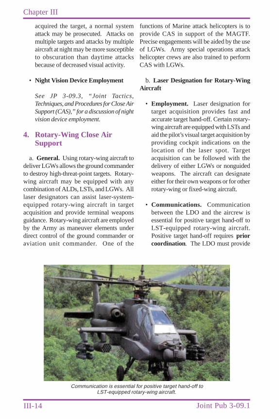
III-14
Chapter III
Joint Pub 3-09.1
acquired the target, a normal systemattack may be prosecuted. Attacks onmultiple targets and attacks by multipleaircraft at night may be more susceptibleto obscuration than daytime attacksbecause of decreased visual activity.
• Night Vision Device Employment
See JP 3-09.3, “Joint Tactics,Techniques, and Procedures for Close AirSupport (CAS),” for a discussion of nightvision device employment.
4. Rotary-Wing Close AirSupport
a. General. Using rotary-wing aircraft todeliver LGWs allows the ground commanderto destroy high-threat-point targets. Rotary-wing aircraft may be equipped with anycombination of ALDs, LSTs, and LGWs. Alllaser designators can assist laser-system-equipped rotary-wing aircraft in targetacquisition and provide terminal weaponsguidance. Rotary-wing aircraft are employedby the Army as maneuver elements underdirect control of the ground commander oraviation unit commander. One of the
functions of Marine attack helicopters is toprovide CAS in support of the MAGTF.Precise engagements will be aided by the useof LGWs. Army special operations attackhelicopter crews are also trained to performCAS with LGWs.
b. Laser Designation for Rotary-WingAircraft
• Employment. Laser designation fortarget acquisition provides fast andaccurate target hand-off. Certain rotary-wing aircraft are equipped with LSTs andaid the pilot’s visual target acquisition byproviding cockpit indications on thelocation of the laser spot. Targetacquisition can be followed with thedelivery of either LGWs or nonguidedweapons. The aircraft can designateeither for their own weapons or for otherrotary-wing or fixed-wing aircraft.
• Communications. Communicationbetween the LDO and the aircrew isessential for positive target hand-off toLST-equipped rotary-wing aircraft.Positive target hand-off requires priorcoordination. The LDO must provide
Communication is essential for positive target hand-off toLST-equipped rotary-wing aircraft.
III-15
Procedures
the appropriate laser code, laser-targetline in degrees magnetic, and laser spotoffset (if applicable).
c. Laser Designation for Rotary-WingAircraft with HELLFIRE LGMs. Thelock-on and launch ranges of LGMs can beseveral miles. LGMs provide extendedstandoff for high-threat targets. The pilot hasseveral options for firing mode, firing method,and missile seeker lock-on.
• Firing Modes
•• Single Fire or Manual Mode. In thesingle-fire mode, one missile islaunched. This mode can be used withautonomous direct, remote direct, andremote indirect fire methods, as discussedbelow.
•• Rapid Fire. Rapid fire is a techniqueof launching two or more missiles onthe same code. Multiple targets can beengaged by launching missiles at least 8seconds or more apart, as specified bythe LDO. Once the first missile hits thefirst target, the LDO must smoothly movethe laser spot to the next target.
•• Ripple Fire. In the ripple fire mode,missiles are fired one after the otheron different codes. For best effect,multiple laser designators should be usedto achieve ripple fire. Each laserdesignator operates on a different lasercode, and the weapon’s seekers are codedto match each designator.
•• Rapid or Ripple Fire. Using multiplecodes and laser designators, thecombination of rapid or ripple fire canbe achieved.
NOTE: Missiles can be launchedsingly in either the rapid or ripplemode.
• Firing Methods
•• Direct Fire Method. Direct fire isachieved using either autonomous orremote laser designators. When usingremote designators, the rotary-wingaircraft is free to resume terrain maskingor engage other targets after each LGMlaunch. This capability is called “fire andforget” and increases aircraftsurvivability and flexibility.
•• Indirect Fire Method. Indirect fireis achieved by using remote laserdesignators. Vulnerability of rotary-wing aircraft to enemy direct-fireweapons and radar detection isminimized by employing LGMs in theindirect-fire method. The LGM islaunched while the aircraft is positionedbehind masking terrain features, like treesand hills. The pilot selects a trajectoryfor the LGM (either high or low) overthe masking terrain feature. The seekerwill then locate and lock-on to the remotelaser-designated target.
• HELLFIRE Missile Seeker Lock-onOptions
•• Lock-on After Launch. The LOALoption can be used in the direct-fire modeand is always used for the indirect-firemethod. The LGM is launched on atrajectory toward the target with seekerlock-on occurring in flight. This optionallows missile launching toward thetarget area during adverse weather, hazydays, long ranges, or temporary targetobscuration. Lock-on will occur whenthe obstruction to the seeker’s viewdissipates or is bypassed during theapproach to the target area.
•• Lock-on Before Launch. The LOBLoption requires direct LOS to the targetand requires the seeker to be locked-onto the target before launch.
III-16
Chapter III
Joint Pub 3-09.1
d. Engagement Procedures
• Communications. Prior coordination isrequired to ensure that communicationsexist between the LDO and the aircrew ofthe laser-equipped rotary-wing aircraft.Coordinating radio frequencies and callsigns may be accomplished by a face-to-face briefing, using signal operatinginstructions or the aviation unit’s operationsorder, or through the FAC.
• HELLFIRE Mission Brief
•• Target Location. The HELLFIREMission brief will be a standard 9-linebrief. Rotary-wing aircraft use the sameCAS briefing form as fixed-wing aircraft.
See Appendix C, “CAS Briefing Form (9-Line)”
•• Codes. The laser designator and theLGW on the helicopter must be on thesame code. HELLFIRE LGM codes canbe set or changed from the cockpit,allowing the aircrew to match the groundlaser designator’s code. LGM designatorcoding is important because it preventsthe seeker from homing in on otherreflected laser energy.
•• Laser-Target Line. The laser-targetline must be given to the aircrew indegrees magnetic. The aircrew needsthis information to align the helicopter,ensuring positive seeker lock-on of theLGM for LOBL delivery or positive in-flight seeker lock-on of the LGM forLOAL. The laser-target line will alsoallow the aircrew to prevent inadvertentlyengaging the laser designator. The LDOmust be outside a 30º by 40º zone fromthe aircraft, but within a 120º cone fromthe target (See Figure III-4).
•• The Firing Mode. A single LDO canrequest single-fire and rapid-fire modes.
Single fire is used to engage a specifictarget. Rapid fire may be used toengage multiple targets. Two LDOsemployed as a team can request ripplefire or rapid and ripple fire. Priorcoordination and thorough pre-missionplanning are necessary for ripple fire orrapid and ripple fire.
•• Number of Missiles. The LDO mayelect to engage multiple targets withmultiple LGMs. This procedure may beadvantageous to a quick attack of targetsat extended ranges. Rapid fire may beused to minimize total LASER-ON timefor multiple targets. For example,LASER-ON time to guide four single-launched missiles might be 1 minute and20 seconds, while LASER-ON time forfour rapid-fire-launched missiles in thesame situation is, at a minimum, 32seconds. During multiple missilelaunches, the LDO must ensure thatlaser energy is not interrupted byobscuration caused by previouslylaunched missiles.
•• Time Interval. During rapid fire,one missile is launched at a minimumof every 8 seconds. An LDO mayrequest a longer interval betweenlaunches. Considerations for longerintervals between LGM launches includeoperator experience, terrain, target array,and battlefield obscuration.
A discussion of ground and airbornedesignation for helicopters is in AppendixB, “Procedures Guide.”
5. Laser Designation for Non-CAS Air Attacks
There may be instances where aircrews andground forces will designate for aircraft notconducting CAS missions, such as interdictionoperations, armed reconnaissance, and otherrelated areas.
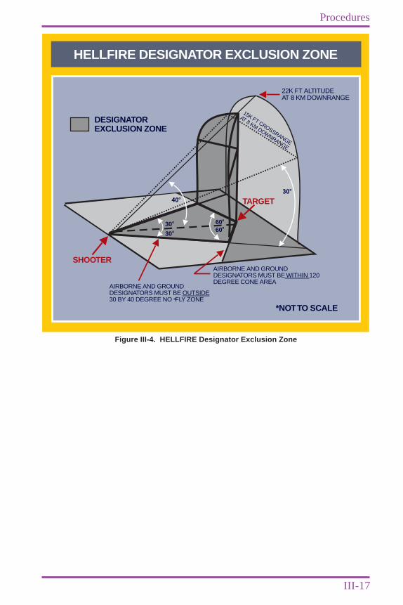
III-17
Procedures
HELLFIRE DESIGNATOR EXCLUSION ZONE
22K FT ALTITUDEAT 8 KM DOWNRANGE
DESIGNATOREXCLUSION ZONE
*NOTTO SCALE
AIRBORNE AND GROUNDDESIGNATORS MUST BE 120DEGREE CONE AREA
WITHIN
AIRBORNE AND GROUNDDESIGNATORS MUST BE30 BY 40 DEGREE NO FLY ZONE
OUTSIDE
15K FT CROSSRANGE
AT 8 KM DOWNRANGE
SHOOTER
TARGET30
o
oo
oo
30 6060
30
40o
Figure III-4. HELLFIRE Designator Exclusion Zone

III-18
Chapter III
Joint Pub 3-09.1
Intentionally Blank
code, the operator must delete the firstnumber and set the last three numbers onthe G/VLLD.
NOTE: Higher PRF (lower numbercodes) provide greater laser energy forthe seeker and LSTs to receive, and soprovide a greater opportunity forsuccess. Lower codes also requiremore power and so cause shorterbattery life.
c. Multiple Codes. Coding allowssimultaneous or nearly simultaneous attackson multiple targets by a single aircraft, orflights of aircraft, employing LGWs set ondifferent codes. This tactic may be employedwhen several high-priority targets need to beattacked expeditiously and can be designatedsimultaneously by the supported unit(s).
2. Management of Coded LaserSystems
Laser codes must be controlled andcoordinated to maximize weaponeffectiveness. The joint force OperationsDirectorate (J-3) has overall responsibility forlaser code management. The J-3 providesblocks of codes to each component. Eachcomponent sub-assigns codes to supportingarms (e.g., Army artillery, Marine air wing,etc.). This controlled code assignmentprevents interference among joint force unitactivities. Each component’s supporting armdivides its codes among its subordinate units.Subordinate units assign codes to individualmissions and change codes periodically, as thesituation requires. At each step of thisprocess, laser codes must be allocated to
CHAPTER IVLASER CODES
IV-1
1. Introduction
a. General. Laser designators and seekersuse a pulse coding system to ensure that aspecific seeker and designator combinationwork in harmony. By setting the same codein both the designator and the seeker, theseeker will track only the energy with thecorrect coding. The seeker will track the firstcorrectly coded, significant laser energy itsees. The seeker will always lock on to themost powerful return in its view. The pulsecoding used by all systems discussed in thismanual is based on PRF.
b. Designator and Seeker Pulse Codes.The designator and seeker pulse codes use amodified octal system that uses the numericaldigits “1” through “8.” The codes are directlycorrelated to a specific PRF, but the code itselfis not the PRF and therefore can becommunicated in the clear as required.Depending on the laser equipment, either athree- or four-digit code can be set. Three-digit code equipment settings range from 111to 788. Four-digit code equipment settingsrange from 1111 to 1788. The three-and four-digit code equipment is compatible, and anymix of equipment can be used in all types oflaser operations. However, when using a mixof three- and four-digit code equipment, allpersonnel must understand that the firstdigit of a four-digit code is always set tonumerical digit “1” . The remaining threedigits will be set to match the three digits ofthe three-digit code equipment. As anexample, a three-digit code of 657 would beset to 1657 on a four-digit code system or viceversa. The G/VLLD only allows for threenumbers to be set. Upon receipt of a 4-digit
“The instruments of battle are valuable only if one knows how to use them.”
Ardant du PicqBattle Studies
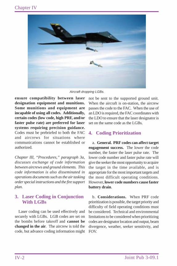
IV-2
Chapter IV
Joint Pub 3-09.1
ensure compatibility between laserdesignation equipment and munitions.Some munitions and equipment areincapable of using all codes. Additionally,certain codes (low code, high PRF, and/orfaster pulse rate) are preferred for lasersystems requiring precision guidance.Codes must be prebriefed to both the FACand aircrews for situations wherecommunications cannot be established orauthorized.
Chapter III, “Procedures,” paragraph 3a,discusses exchange of code informationbetween aircrews and ground elements. Thiscode information is also disseminated inoperations documents such as the air taskingorder special instructions and the fire supportplan.
3. Laser Coding in ConjunctionWith LGBs
Laser coding can be used effectively andsecurely with LGBs. LGB codes are set onthe bombs before takeoff and cannot bechanged in the air. The aircrew is told thecode, but advance coding information might
not be sent to the supported ground unit.When the aircraft is on-station, the aircrewpasses the code to the FAC. When the use ofan LDO is required, the FAC coordinates withthe LDO to ensure that the laser designator isset on the same code as the LGBs.
4. Coding Prioritization
a. General. PRF codes can affect targetengagement success. The lower the codenumber, the faster the laser pulse rate. Thelower code number and faster pulse rate willgive the seeker the most opportunity to acquirethe target in the time available, and isappropriate for the most important targets andthe most difficult operating conditions.However, lower code numbers cause fasterbattery drain .
b. Considerations. When PRF codeprioritization is possible, the target priority anddifficulty of field operating conditions mustbe considered. Technical and environmentallimitations to be considered when prioritizingcodes are designator location and output, beamdivergence, weather, seeker sensitivity, andFOV.
Aircraft dropping LGBs.
CHAPTER VSAFETY
V-1
1. General
The safety considerations discussed hereinare not all-inclusive. The primary sourceof danger from laser designators is the laserbeam itself. The invisible beam is highlydirectional, intense IR radiation that can causeserious harm to the eyes. Due to the relativelylow power levels of LTDs, the laser beam doesnot normally affect other parts of the body.When used properly and with dueconsideration of the laser hazards outlined inthis chapter, laser designators are safe to usein a training environment, as well as foroperational use.
Refer to Military Handbook 828A, “LaserSafety on Ranges and in Other OutdoorAreas,” for laser safety planning, buffer zoneand eye protection information.
2. Laser Eye Safety
a. Friendly Ground Combat Personneland Noncombatant Civilians. The potentialdanger of eye damage to friendly personneland noncombatant civilians must always beconsidered when using laser designators in abattlefield environment where areas occupiedby friendly and enemy troops andnoncombatant civilians are not well defined.Proper operating procedures andguidelines must be established and followedto protect friendly troops and noncombatantcivilians. Each Service has determined thenecessary safety precautions required forusing their respective laser systems. Theseprecautions typically include: (1) establishing
“For they had learned that true safety was to be found in long previous training,and not in eloquent exhortations uttered when they were going into action.”
ThucydidesThe History of the Peloponnesian W ar
laser system nominal ocular hazard distances(NOHDs) or minimum safe direct beamviewing distances (aided and unaided); (2)establishing the appropriate laser eyeprotection (LEP) requirements (wavelengthand optical density); and (3) publishing thetechnical and safety publications necessary forsafe and effective laser system employment.For aircrew using direct-view NVGs (i.e., AN/AVS-6, AN/AVS-9, Type I Design), aninherent degree of protection is afforded tothe central field of vision. This protection isprovided by the internal structure of the imageintensifier tube acting as a mechanical stopagainst the laser energy. However, aircrewperipheral vision still remains vulnerable tostray reflections and/or off axis viewing. LEPspectacles that fit behind NVGs are currentlybeing developed to protect aircrew peripheralvision. However, compatibility challengesstill exist for aircrew integration of these LEPspectacles into their NVG-aided operations.Aircrew using projected image NVGs (i.e.,MXU-810/U CATSEYE, Type II), areafforded no central vision protection due tothe transparent qualities of the NVG’scombiner lens design. Consequently, forthese aircrew, LEP can only be providedthrough the use of LEP spectacles. Inaddition to aircrew LEP, LASER protectionfor the NVGs is now available with theintroduction of the light interference filter(LIF). The LIF is an out-of-band opticalfilter designed to protect AN/AVS-6 I2tubes from LASER damage. The LIF doesnot provide any additional protection for thehuman eye, however; it simply laser-hardens the NVGs.
V-2
Chapter V
Joint Pub 3-09.1
b. Eye Injury. The primary danger fromcurrently fielded laser designators is to the eye.The laser beam’s highly directional, invisibleIR radiation can be refracted by the corneaand eye’s lens and transmitted through thevitreous humor onto the retina, causingdamage ranging from unnoticeable tiny spotsto complete blindness. The principal dangersto the eye result from looking directly back atthe laser and from laser reflections off specular(mirrorlike) reflectors. The laser system’sinherent concentrated energy output, coupledwith a relatively small beam divergence,results in NOHDs for the unaided eye thatmay range for several kilometers, dependentupon the system’s specifications. In addition,if individuals are using direct view magnifyingoptical systems (i.e., 7X50 binocular, AH-1W13X telescopic sighting unit, etc.), the NOHDsare extended to even greater ranges to accountfor the magnification power of the devices.Operators must use extreme care to avoidh i t t i ng f r i end l y pe rsonne l andnoncombatant civilians with the laser beamduring operations. Specific laser equipmentmanuals provide minimum safe distances forequipment being used. Individual trainingranges have safety regulations that also specifysafe distances for laser equipment.
Refer to Chapter I, “Concept,” paragraph 2f,and Appendix E, “Laser Protocol,” for legalrestrictions on the use of lasers.
c. Reflections. Reflections from flatobjects like mirrors, window glass, reflectorson vehicle tail lights, and certain opticalsystems do not spread the beam afterreflection. These reflections, therefore, cancause eye injury. To calculate the NOHD fora specular reflection, one would use the sameintrabeam NOHD and add the sum of thedistance from the laser system to the target(specular reflective surface) with the distanceback to the viewer. If the sum of thesedistances is equal to or greater than theNOHD, the viewer would not be at risk forinjury. In contrast to a specular reflection, if
the incident laser energy strikes a curved orrough surface, the energy will be reflected orspread in all directions. This diffuse reflectionposes minimal concern for eye injury due tothe decreased intensity and dissociated natureof these reflections. However, some laserdesignators may possess enough energy, evenfrom a diffuse reflection, to still cause injuryto the eye. These systems are said to possessa diffuse reflection viewing hazard.Fortunately, the distances associated with lasersystem diffuse reflection hazards are typicallyless than 100 meters, or well within thefragmentation envelope of the LGW in use.Therefore, a diffuse reflection hazard wouldnot likely affect operational employment ortactics. The minimum safe range increasessignificantly for anyone viewing a targetarea through binoculars and othermagnifying optics.
d. Enemy Personnel. Current US policyon laser use states that US forces will notuse lasers specifically designed to causepermanent blindness. It also states that USforces will strive to minimize accidental orincidental eye injuries resulting from laseruse, but recognizes that some injuries mayoccur as a result of these systems. None ofthe laser systems described in thispublication were designed for the purposeof causing eye injury. They should be usedproperly against enemy targets as thesituation dictates
See Appendix E, “Laser Protocol.”
3. Fratricide
Designator profiles behind the launchplatform are inherently the safest and willminimize the possibility of fratricide. Thepossibility of fratricide still exists whileoperating anywhere within the optimal attackzone. It is highest in the designated safetyzone or when a false lock-on is achieved.Attack headings should be planned withconsideration for friendly forces and

V-3
Safety
noncombatant civilian locations. Ultimatelythe primary mechanisms for limitingfratricide are command emphasis,disciplined operations, close coordinationamong component commands, rehearsals,and enhanced situational awareness.
4. Organizational SafetyConsiderations
Each unit involved with laser weaponsystems employment must establish andenforce laser safety standard operatingprocedures. Dissemination of current safety,procedural, and regulatory information is
essential to safe employment of laserweapon systems. Equipment performancecharacteristics and operating rangerequirements are extensive and dictate whatcan safely be accomplished. Planners andusers must research and follow the mostcurrent laser safety information, directives,and regulations.
Delivery parameters and considerations forspecific weapons are in FM 101-50-31/TH 61A1-3-9/FMFM 5-2G-6/NAVAIR 00-130ASR-9,“Joint Munitions Effectiveness Manual/Air toSurface (JMEM/AS), Risk Estimates forFriendly Troops” (C), 19 December 1986.

V-4
Chapter V
Joint Pub 3-09.1
Intentionally Blank
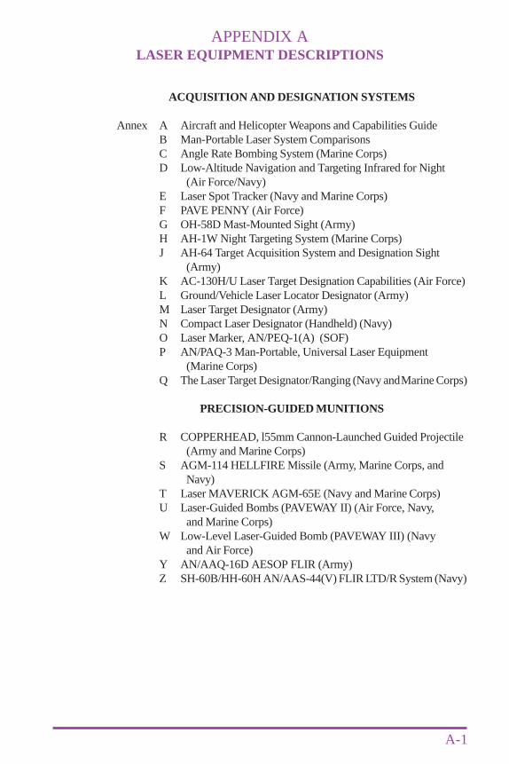
APPENDIX ALASER EQUIPMENT DESCRIPTIONS
A-1
ACQUISITION AND DESIGNATION SYSTEMS
Annex A Aircraft and Helicopter Weapons and Capabilities GuideB Man-Portable Laser System ComparisonsC Angle Rate Bombing System (Marine Corps)D Low-Altitude Navigation and Targeting Infrared for Night
(Air Force/Navy)E Laser Spot Tracker (Navy and Marine Corps)F PAVE PENNY (Air Force)G OH-58D Mast-Mounted Sight (Army)H AH-1W Night Targeting System (Marine Corps)J AH-64 Target Acquisition System and Designation Sight
(Army)K AC-130H/U Laser Target Designation Capabilities (Air Force)L Ground/Vehicle Laser Locator Designator (Army)M Laser Target Designator (Army)N Compact Laser Designator (Handheld) (Navy)O Laser Marker, AN/PEQ-1(A) (SOF)P AN/PAQ-3 Man-Portable, Universal Laser Equipment
(Marine Corps)Q The Laser Target Designator/Ranging (Navy and Marine Corps)
PRECISION-GUIDED MUNITIONS
R COPPERHEAD, l55mm Cannon-Launched Guided Projectile(Army and Marine Corps)
S AGM-114 HELLFIRE Missile (Army, Marine Corps, andNavy)
T Laser MAVERICK AGM-65E (Navy and Marine Corps)U Laser-Guided Bombs (PAVEWAY II) (Air Force, Navy,
and Marine Corps)W Low-Level Laser-Guided Bomb (PAVEWAY III) (Navy
and Air Force)Y AN/AAQ-16D AESOP FLIR (Army)Z SH-60B/HH-60H AN/AAS-44(V) FLIR LTD/R System (Navy)
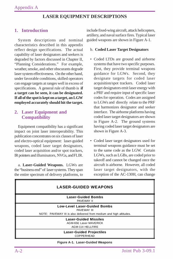
A-2
Appendix A
Joint Pub 3-09.1
1. Introduction
System descriptions and nominalcharacteristics described in this appendixreflect design specifications. The actualcapability of laser designators and seekers isdegraded by factors discussed in Chapter II,“Planning Considerations.” For example,weather, smoke, and other obscurants degradelaser system effectiveness. On the other hand,under favorable conditions, skilled operatorscan engage targets at ranges well in excess ofspecifications. A general rule of thumb is ifa target can be seen, it can be designated.If all of the spot is kept on a target, an LGWemployed accurately should hit the target.
2. Laser Equipment andCompatibility
Equipment compatibility has a significantimpact on joint laser interoperability. Thispublication concentrates on six classes of laserand electro-optical equipment: laser-guidedweapons, coded laser target designators,coded laser acquisition and/or spot trackers,IR pointers and illuminators, NVGs, and FLIR.
a. Laser-Guided Weapons. LGWs arethe “business end” of laser systems. They spanthe entire spectrum of delivery platforms, to
LASER EQUIPMENT DESCRIPTIONS
include fixed-wing aircraft, attack helicopters,artillery, and naval surface fires. Typical laserguided weapons are shown in Figure A-1.
b. Coded Laser Target Designators
• Coded LTDs are ground and airbornesystems that have two specific purposes.First, they provide terminal weaponsguidance for LGWs. Second, theydesignate targets for coded laseracquisition/spot trackers. Coded lasertarget designators emit laser energy witha PRF and require input of specific lasercodes for operation. Codes are assignedto LGWs and directly relate to the PRFthat harmonizes designator and seekerinterface. The airborne platforms havingcoded laser target designators are shownin Figure A-2. The ground systemshaving coded laser target designators areshown in Figure A-3.
• Coded laser target designators used forterminal weapons guidance must be setto the same code as the LGW. CertainLGWs, such as LGBs, are coded prior totakeoff and cannot be changed once theaircraft is airborne. However, all codedlaser target designators, with theexception of the AC-130H, can change
Figure A-1. Laser-Guided Weapons
LASER-GUIDED WEAPONS
Laser-Guided Bombs PAVEWAY II
Low-Level Laser-Guided Bombs PAVEWAY III
NOTE: PAVEWAY III is also delivered from medium and high altitudes.
Laser-Guided Missiles AGM-65E Laser MAVERICK
AGM-114 HELLFIRE
Laser-Guided Pro jectilesCOPPERHEAD
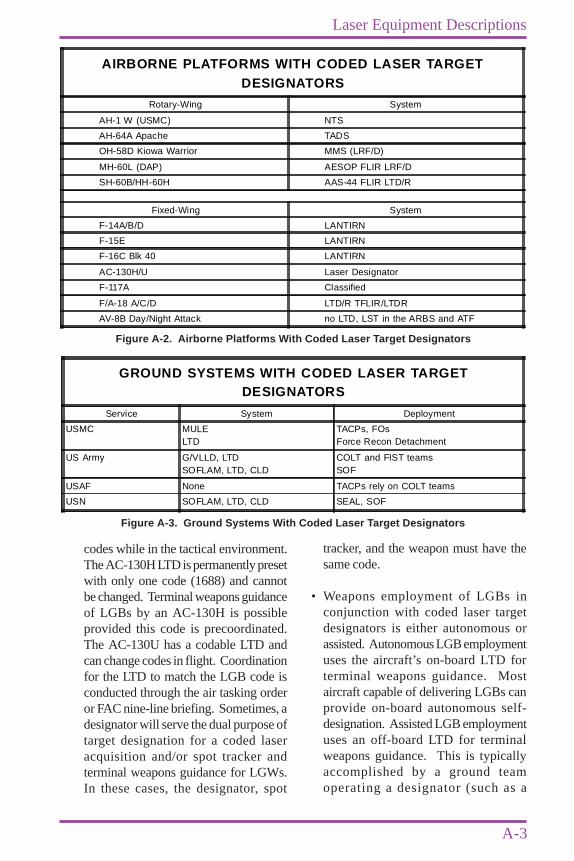
A-3
Laser Equipment Descriptions
codes while in the tactical environment.The AC-130H LTD is permanently presetwith only one code (1688) and cannotbe changed. Terminal weapons guidanceof LGBs by an AC-130H is possibleprovided this code is precoordinated.The AC-130U has a codable LTD andcan change codes in flight. Coordinationfor the LTD to match the LGB code isconducted through the air tasking orderor FAC nine-line briefing. Sometimes, adesignator will serve the dual purpose oftarget designation for a coded laseracquisition and/or spot tracker andterminal weapons guidance for LGWs.In these cases, the designator, spot
tracker, and the weapon must have thesame code.
• Weapons employment of LGBs inconjunction with coded laser targetdesignators is either autonomous orassisted. Autonomous LGB employmentuses the aircraft’s on-board LTD forterminal weapons guidance. Mostaircraft capable of delivering LGBs canprovide on-board autonomous self-designation. Assisted LGB employmentuses an off-board LTD for terminalweapons guidance. This is typicallyaccomplished by a ground teamoperating a designator (such as a
AIRBORNE PLATFORMS WITH CODED LASER TARGETDESIGNATORS
Rotary-Wing System
AH-1 W (USMC) NTS
AH-64A Apache TADS
OH-58D Kiowa Warrior MMS (LRF/D)
MH-60L (DAP) AESOP FLIR LRF/D
SH-60B/HH-60H AAS-44 FLIR LTD/R
Fixed-Wing System
F-14A/B/D LANTIRN
F-15E LANTIRN
F-16C Blk 40 LANTIRN
AC-130H/U Laser Designator
F-117A Classified
F/A-18 A/C/D LTD/R TFLIR/LTDR
AV-8B Day/Night Attack no LTD, LST in the ARBS and ATF
Figure A-2. Airborne Platforms With Coded Laser Target Designators
GROUND SYSTEMS WITH CODED LASER TARGETDESIGNATORS
Service System Deployment
USMC MULELTD
TACPs, FOsForce Recon Detachment
US Army G/VLLD, LTDSOFLAM, LTD, CLD
COLT and FIST teamsSOF
USAF None TACPs rely on COLT teams
USN SOFLAM, LTD, CLD SEAL, SOF
Figure A-3. Ground Systems With Coded Laser Target Designators
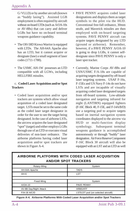
A-4
Appendix A
Joint Pub 3-09.1
G/VLLD) or by another aircraft (knownas “buddy lasing”). Assisted LGBemployment is often required by aircraftwithout on-board LTDs (such as A/OA-10sor AV-8Bs) that can carry and deliverLGBs but have no on-board terminalweapons guidance capability.
• The OH-58D Kiowa Warrior is equippedwith LTDs. The AH-64A Apache alsohas an LTD, but it cannot acquire ordesignate (lase) a small segment of lasercodes (1711-1788).
• The USMC AH-1W possesses an LTDcompatible with all LGWs, includingHELLFIRE missiles.
c. Coded Laser Acquisition and/or SpotTrackers
• Coded laser acquisition and/or spottrackers are systems which allow visualacquisition of a coded laser designatedtarget. LSTs must be set to the same codeas the coded laser target designator inorder for the user to see the target beingdesignated. In the case of airborne LSTs,the aircrew acquires the laser designated“spot” (target) and either employs LGBsthrough use of an LTD or executes visualdeliveries of non-laser ordnance. Theairborne platforms having coded laseracquisition and/or spot trackers areshown in Figure A-4.
• PAVE PENNY acquires coded laserdesignations and displays them as targetsymbols to the pilot via the HUD.Conventional free-fall ordnance, 30mmstrafe, and Maverick missiles are thenemployed with on-board targetingsystems. PAVE PENNY aircraft canacquire targets designated by any LTD(ground or airborne). Remember,however, if a PAVE PENNY A/OA-10is going to drop LGBs, it cannot self-designate since PAVE PENNY is only alaser spot tracker.
• Currently, Marine Corps AV-8Bs andUSN/USMC F/A-18s are capable ofacquiring targets designated by off-boardlaser targeting systems. USAF F-16s,F-15Es and US Navy F-14s do not haveLSTs and are incapable of visuallyacquiring coded laser designated targetsfrom off-board systems. Low-altitudenavigation and targeting infrared fornight (LANTIRN) equipped fighters(F-16C Block 40, F-15E, and F-14A/B/D)use a targeting pod to acquire targetsbased on inertial navigation systemcoordinates displayed to the aircrew viaHUD or multi-function displaysymbology. Subsequent terminalweapons guidance is accomplishedautonomously or through “buddy” laserdesignation. Air Force Reserve ComponentF-16C Block 30 aircraft will also beequipped with an LST and an LTD as well
AIRBORNE PLATFORMS WITH CODED LASER ACQUISITIONAND/OR SPOT TRACKERS
Rotary-Wing System
AH-64A Apache TADS
AH-6 LST
Fixed-Wing System
A/OA-10 PAVE PENNY
AV-8B Day/Night Attack ARBS/ATF
F/A-18 A/C/D LST/LDT pod (on selected aircraft)
Figure A-4. Airborne Platforms With Coded Laser Acquisition and/or Spot Trackers
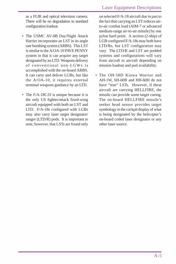
A-5
Laser Equipment Descriptions
as a FLIR and optical television camera.There will be no degradation in standardconfiguration loadout.
• The USMC AV-8B Day/Night AttackHarrier incorporates an LST in its anglerate bombing system (ARBS). This LSTis similar to the A/OA-10 PAVE PENNYsystem in that it can acquire any targetdesignated by an LTD. Weapons deliveryof convent iona l non-LGWs isaccomplished with the on-board ARBS.It can carry and deliver LGBs, but likethe A/OA-10, it requires externalterminal weapons guidance by an LTD.
• The F/A-18C/D is unique because it isthe only US fighter/attack fixed-wingaircraft equipped with both an LST andLTD. F/A-18s configured with LGBsmay also carry laser target designator/ranger (LTD/R) pods. It is important tonote, however, that LSTs are found only
on selected F/A-18 aircraft due in part tothe fact that carrying an LST reduces air-to-air combat load (AIM-7 or advancedmedium-range air-to-air missile) by onepylon hard point. A section (2-ship) ofLGB configured F/A-18s may both haveLTD/Rs, but LST configuration mayvary. The LTD/R and LST are poddedsystems and configurations will varyfrom aircraft to aircraft depending onmission loadout and pod availability.
• The OH-58D Kiowa Warrior andAH-1W, SH-60B and HH-60H do nothave “true” LSTs. However, if theseaircraft are carrying HELLFIRE, themissile can provide some target cueing.The on-board HELLFIRE missile’sseeker head sensor provides targetsymbology in the cockpit display of whatis being designated by the helicopter’son-board coded laser designator or anyother laser source.

A-6
Appendix A
Joint Pub 3-09.1
Intentionally Blank

NOTE: Data contained in thisappendix is provided only forinformation. It is not authoritative andshould be verified before being usedoperationally.
ANNEX A TO APPENDIX AAIRCRAFT AND HELICOPTER WEAPONS
AND CAPABILITIES GUIDE
A-A-1
The capabilities of fixed-wing aircraft areshown in Figure A-A-1. The capabilities ofrotary-wing aircraft are shown in FigureA-A-2.

A-A-2
Annex A to Appendix A
Joint Pub 3-09.1
Figure A-A-1. Fixed-Wing Aircraft Capabilities
FIXED-WING AIRCRAFT CAPABILITIES
AircraftM/D/S
UsingService
Ordnance Laser CapabilityLST LTD
MarkingCapability
BeaconCapability
OtherSystems
AV-8B(Day Attack)
USMC Laser-guidedbombs*AGM-65 MaverickGP bombsNapalm2.75” rockets5.00” rocketsLUU-225mm cannonAGM-122 SidearmAerial minesCBUs
YES NO Rockets None ARBSNVGGPS
AV-8B(Night Attack)
USMC As above YES NO Rockets None TVNVGNAVFLIRGPS
AV-8B(Night/Radar)
USMC As above NO NO Rockets None NVGNAVFLIRGPSRadar
A/OA-10 USAF Laser-guidedbombs*AGM-65 MaverickGP bombsCBUsAerial mines2.75” rocketsLUU-2/19LUU-1/-5/-6 flares30mm cannon
YES NO WP rockets30mm HEIHE rockets
None NVG
AC-130H USAF(SOF)
105mm howitzer40 mm cannon20mm cannon
NO YES GLINT105mm WP105mm HE40mmMISCHLTD (1688only)
PPN-19ST-181SSBPLS
FLIRLLLTVRadarGPS
AC-130U USAF(SOF)
105mm howitzer40mm cannon25 mm cannon
NO YES GLINT105mm WP105mm HE40mmMISCH(codableLTD)
SST-181 FLIRALTVRadarGPS
B-1B USAF GP bombsCBUs
NO NO None PPN-19*** Radar
B-2 USAF Mk 82/84CBU 87 (CEM)/89 (GATOR)/97 (SFW)GBU 31 (JDAM)GBU 34
NO NO None None GPSRadar

A-A-3
Aircraft and Helicopter Weapons and Capabilities Guide
FIXED-WING AIRCRAFT CAPABILITIES (cont’d)
AircraftM/D/S
UsingService
Ordnance Laser CapabilityLST LTD
MarkingCapability
BeaconCapability
OtherSystems
B-52H USAF AGM-142GP bombsAerial minesLaser-guidedbombsCBUs
NO NO None PPN-19***PPN-20***
FLIRLLLTVGPSNVGRadar
F-14/A/B/D USN Laser-guidedbombsGP bombs20mm cannonCBUsAerial minesLUU-2
NO YES Laser None NVGLANTIRNFLIRGPS
F-15E USAF Laser-guidedbombsCBUsGP bombs20mm cannonAGM-65 Maverick
NO YES Laser PPN-19PPN-20
FLIRRadarsAAM
F-16(withoutLANTIRN)
USAF AGM-65 MaverickLaser-guidedbombs*GP bombsCBUs20mm cannon
NO NO WP rockets PPN-19PPN-20
RadarGPS**
F-16C/D(withLANTIRN)
USAF Laser-guidedbombs*AGM-65 MaverickGP bombsCBUs20mm cannon
NO YES Laser PPN-19PPN-20
FLIRGPSNVGRadar
F-117 USAF GBU 10/12GBU 27Mk 82/84CBU 52/58/71/87(CEM)/89 (Gator)Mk 20
YES YES Laser None GPSINSFLIRDLIR
Figure A-A-1. Fixed-Wing Aircraft Capabilities (cont’d)
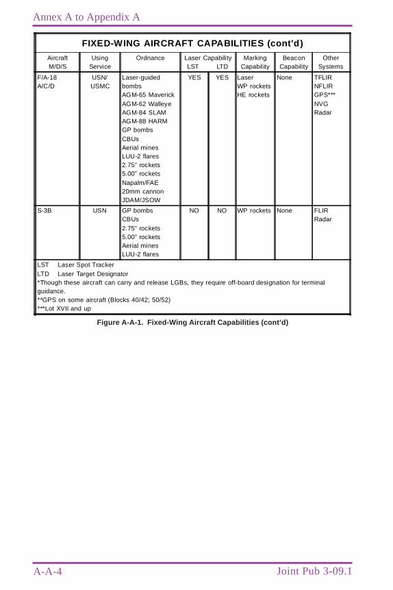
A-A-4
Annex A to Appendix A
Joint Pub 3-09.1
Figure A-A-1. Fixed-Wing Aircraft Capabilities (cont’d)
FIXED-WING AIRCRAFT CAPABILITIES (cont’d)
AircraftM/D/S
UsingService
Ordnance Laser CapabilityLST LTD
MarkingCapability
BeaconCapability
OtherSystems
F/A-18A/C/D
USN/USMC
Laser-guidedbombsAGM-65 MaverickAGM-62 WalleyeAGM-84 SLAMAGM-88 HARMGP bombsCBUsAerial minesLUU-2 flares2.75” rockets5.00” rocketsNapalm/FAE20mm cannonJDAM/JSOW
YES YES LaserWP rocketsHE rockets
None TFLIRNFLIRGPS***NVGRadar
S-3B USN GP bombsCBUs2.75” rockets5.00” rocketsAerial minesLUU-2 flares
NO NO WP rockets None FLIRRadar
LST Laser Spot TrackerLTD Laser Target Designator*Though these aircraft can carry and release LGBs, they require off-board designation for terminalguidance.**GPS on some aircraft (Blocks 40/42; 50/52)***Lot XVII and up
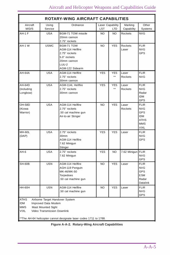
A-A-5
Aircraft and Helicopter Weapons and Capabilities Guide
Figure A-A-2. Rotary-Wing Aircraft Capabilities
ROTARY-WING AIRCRAFT CAPABILITIES
AircraftM/D/S
UsingService
Ordnance Laser CapabilityLST LTD
MarkingCapability
OtherSystems
AH-1 F USA BGM-71 TOW missile20mm cannon2.75” rockets
NO NO Rockets NVG
AH-1 W USMC BGM-71 TOWAGM-114 Hellfire2.75” rockets5.0” rockets20mm cannonLUU-2AGM-122 Sidearm
NO YES RocketsLaser
FLIRNVGGPS
AH-64A USA AGM-114 Hellfire2.75” rockets30mm cannon
YES YES**
LaserRockets
FLIRNVG
AH-64D(includingLongbow)
USA AGM-114L Hellfire2.75” rockets30mm cannon
YES YES**
LaserRockets
FLIRNVGRadarIDMGPS
OH-58D(KiowaWarrior)
USA AGM-114 Hellfire2.75” rockets.50 cal machine gunAir-to-air Stinger
NO YES LaserRockets
FLIRNVGGPSIDMATHSMMSVIXL
MH-60L(DAP)
USA 2.75” rockets30mmAGM-114 Hellfire7.62 MinigunStinger
YES YES Laser FLIRNVGGPS
AH-6 USA 2.75” rockets7.62 Minigun
YES NO 7.62 Minigun FLIRNVGGPS
SH-60B USN AGM-114 HellfireAGH-119 PenguinMK-46/MK-50Torpedoes.50 cal machine gun
NO YES Laser FLIRNVGGPSESMRadarDatalink
HH-60H USN AGM-114 Hellfire.50 cal machine gun
NO YES Laser FLIRNVGGPS
ATHS Airborne Target Handover SystemIDM Improved Data ModemMMS Mast Mounted SightVIXL Video Transmission Downlink
**The AH-64 helicopter cannot designate laser codes 1711 to 1788.

A-A-6
Annex A to Appendix A
Joint Pub 3-09.1
Intentionally Blank

ANNEX B TO APPENDIX AMAN-PORTABLE LASER SYSTEM COMPARISONS
A-B-1
Figure A-B-1. Man-Portable Laser System Comparisons
MAN-PORTABLE LASER SYSTEM COMPARISONSAN/PEQ-1 AN/PEQ-1A MULE GVLLD CLD
Magnification 7x 10x 10x 13x 7x
RemoteControl
Cable 150 ft 10 ft or150 ft
N/A N/A 2 ft
RF 5 km 5 km N/A N/A N/A
Duty Cycle(@ 20 pps)
(min)
c320F 5 on, 1 offx3
30 cool down
5 on, 1 offx3
30 cool down
5see note 1
9see note 1
1 on,2 off
a320F 5 on, 1 offx3
30 cool down
5 on, 1 offx3
30 cool down
a3see note 1
4.5see note 1
1 on,2 off
Battery Type BA-5590Lithium, BB-590 NiCad,lead Acid or
Vehicular
BA-5590Lithium, BB-590 NiCad,lead Acid or
Vehicular
BA-6699specialNiCad
BA-6699specialNiCad
UniqueLead-Acid
Battery Life(min)
(@ 20 pps)
c320F 90 (Lithium) 90 (Lithium) 5 9 60
a320F 90 (Lithium) 90 (Lithium) a3 3 to 6.5 60
Cooling Circulatedliquid, self-contained
Circulatedliquid, self-contained
HighpressureNitrousOxide
HighpressureNitrogen
Non-circulatedliquid, self-contained
Night Vision 1.06 I2
available(Integral
Weaver rail)See Note 2
1.06 I2
available(Integral
Weaver &Picatinney
rails)
CryoThermal
(Bottle Type)
CyroThermal
(Bottle type)
N/A
Warm-up Time(seconds)
5 5 5 3 5
RangeResolution
(meters)
35 35 10 35 35
Range Logic 1st/Last 1st/Last 1st (gated) 1st/Last(gated)
1st/Last
Minimum TargetSeparation
(meters)
35 35 c50 c20 35
Effective Range Designate 5 km(c32 0F)
5 km 3.4 km 5 km a5 km(3 km typical)
Range Finding 10 km 10 km 10 km 10 km 10 km
Note 1. This duty cycle is based on the battery life/operating time of the laser system.Note 2. This night sight is capable of imaging the laser wavelength day or night with the use of daylightfilters.
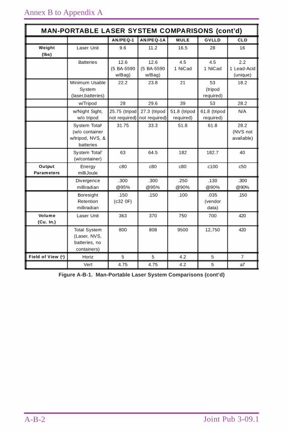
A-B-2
Annex B to Appendix A
Joint Pub 3-09.1
Figure A-B-1. Man-Portable Laser System Comparisons (cont’d)
MAN-PORTABLE LASER SYSTEM COMPARISONS (cont’d)AN/PEQ-1 AN/PEQ-1A MULE GVLLD CLD
Weight
(lbs)
Laser Unit 9.6 11.2 16.5 28 16
Batteries 12.6(5 BA-5590
w/Bag)
12.6(5 BA-5590
w/Bag)
4.51 NiCad
4.51 NiCad
2.21 Lead-Acid
(unique)
Minimum UsableSystem
(laser,batteries)
22.2 23.8 21 53(tripod
required)
18.2
w/Tripod 28 29.6 39 53 28.2
w/Night Sight,w/o tripod
25.75 (tripodnot required)
27.3 (tripodnot required)
51.8 (tripodrequired)
61.8 (tripodrequired)
N/A
System Total1
(w/o containerw/tripod, NVS, &
batteries
31.75 33.3 51.8 61.8 28.2(NVS notavailable)
System Total2
(w/container)63 64.5 182 182.7 40
OutputParameters
EnergymilliJoule
c80 c80 c80 c100 c50
Divergencemilliradian
.300@95%
.300@95%
.250@90%
.130@90%
.300@90%
BoresightRetentionmilliradian
.150(c32 0F)
.150 .100 .035(vendor
data)
.150
Volume(Cu. In.)
Laser Unit 363 370 750 700 420
Total System(Laser, NVS,batteries, nocontainers)
800 808 9500 12,750 420
Field of View ( o) Horiz 5 5 4.2 5 7
Vert 4.75 4.75 4.2 5 a7
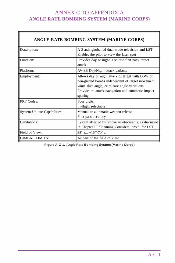
ANNEX C TO APPENDIX AANGLE RATE BOMBING SYSTEM (MARINE CORPS)
A-C-1
Figure A-C-1. Angle Rate Bombing System (Marine Corps)
ANGLE RATE BOMBING SYSTEM (MARINE CORPS)
Description: A 3-axis gimballed dual-mode television and LSTEnables the pilot to view the laser spot
Function: Provides day or night, accurate first pass, targetattack
Platform: AV-8B Day/Night attack variants
Employment: Allows day or night attack of target with LGW ornon-guided bombs independent of target movement,wind, dive angle, or release angle variationsProvides re-attack navigation and automatic impactspacing
PRF Codes: Four digitsIn-flight selectable
System-Unique Capabilities: Manual or automatic weapon releaseFirst-pass accuracy
Limitations: System affected by smoke or obscurants, as discussedin Chapter II, “Planning Considerations,” for LST
Field of View: 35o az, +15o/-70o el
GIMBAL LIMITS: As part of the field of view

A-C-2
Annex C to Appendix A
Joint Pub 3-09.1
Intentionally Blank
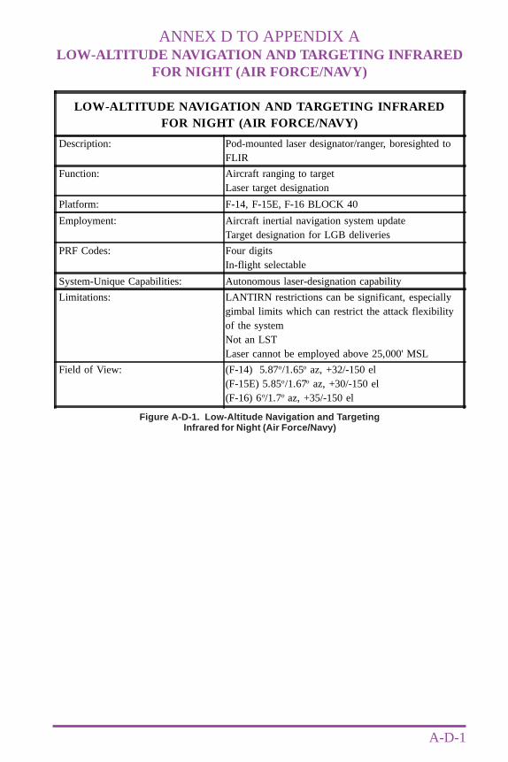
ANNEX D TO APPENDIX ALOW-ALTITUDE NAVIGATION AND TARGETING INFRARED
FOR NIGHT (AIR FORCE/NAVY)
A-D-1
Figure A-D-1. Low-Altitude Navigation and TargetingInfrared for Night (Air Force/Navy)
LOW-ALTITUDE NAVIGATION AND TARGETING INFRAREDFOR NIGHT (AIR FORCE/NAVY)
Description: Pod-mounted laser designator/ranger, boresighted toFLIR
Function: Aircraft ranging to targetLaser target designation
Platform: F-14, F-15E, F-16 BLOCK 40
Employment: Aircraft inertial navigation system updateTarget designation for LGB deliveries
PRF Codes: Four digitsIn-flight selectable
System-Unique Capabilities: Autonomous laser-designation capability
Limitations: LANTIRN restrictions can be significant, especiallygimbal limits which can restrict the attack flexibilityof the systemNot an LSTLaser cannot be employed above 25,000' MSL
Field of View: (F-14) 5.87o/1.65o az, +32/-150 el(F-15E) 5.85o/1.67o az, +30/-150 el(F-16) 6o/1.7o az, +35/-150 el

A-D-2
Annex D to Appendix A
Joint Pub 3-09.1
Intentionally Blank
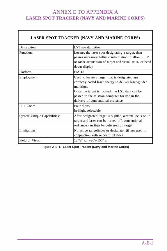
ANNEX E TO APPENDIX ALASER SPOT TRACKER (NAVY AND MARINE CORPS)
A-E-1
Figure A-E-1. Laser Spot Tracker (Navy and Marine Corps)
LASER SPOT TRACKER (NAVY AND MARINE CORPS)
Description: LST see definition
Function: Locates the laser spot designating a target, thenpasses necessary ballistic information to allow FLIRor radar acquisition of target and visual HUD or headdown display
Platform: F/A-18
Employment: Used to locate a target that is designated anycorrectly coded laser energy to deliver laser-guidedmunitionsOnce the target is located, the LST data can bepassed to the mission computer for use in thedelivery of conventional ordnance
PRF Codes: Four digitsIn-flight selectable
System-Unique Capabilities: After designated target is sighted, aircraft locks on totarget and laser can be turned off; conventionalordnance can then be delivered on target
Limitations: No active rangefinder or designator (if not used inconjunction with onboard LTD/R)
Field of View: 12o/3o az, +30o/-150o el

A-E-2
Annex E to Appendix A
Joint Pub 3-09.1
Intentionally Blank
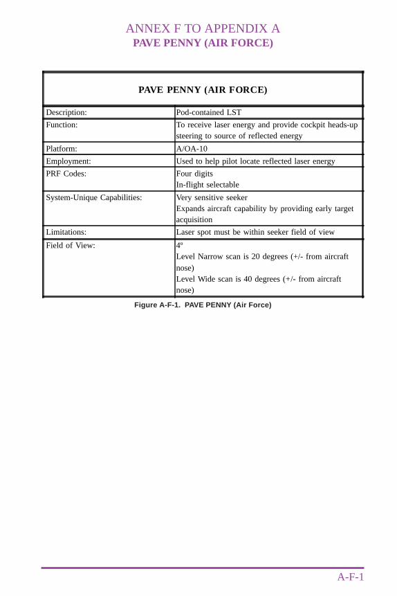
ANNEX F TO APPENDIX APAVE PENNY (AIR FORCE)
A-F-1
Figure A-F-1. PAVE PENNY (Air Force)
PAVE PENNY (AIR FORCE)
Description: Pod-contained LST
Function: To receive laser energy and provide cockpit heads-upsteering to source of reflected energy
Platform: A/OA-10
Employment: Used to help pilot locate reflected laser energy
PRF Codes: Four digitsIn-flight selectable
System-Unique Capabilities: Very sensitive seekerExpands aircraft capability by providing early targetacquisition
Limitations: Laser spot must be within seeker field of view
Field of View: 4ºLevel Narrow scan is 20 degrees (+/- from aircraftnose)Level Wide scan is 40 degrees (+/- from aircraftnose)

A-F-2
Annex F to Appendix A
Joint Pub 3-09.1
Intentionally Blank
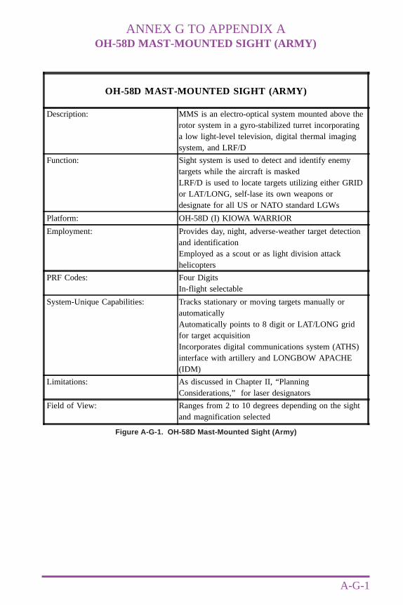
ANNEX G TO APPENDIX AOH-58D MAST-MOUNTED SIGHT (ARMY)
A-G-1
Figure A-G-1. OH-58D Mast-Mounted Sight (Army)
OH-58D MAST-MOUNTED SIGHT (ARMY)
Description: MMS is an electro-optical system mounted above therotor system in a gyro-stabilized turret incorporatinga low light-level television, digital thermal imagingsystem, and LRF/D
Function: Sight system is used to detect and identify enemytargets while the aircraft is maskedLRF/D is used to locate targets utilizing either GRIDor LAT/LONG, self-lase its own weapons ordesignate for all US or NATO standard LGWs
Platform: OH-58D (I) KIOWA WARRIOR
Employment: Provides day, night, adverse-weather target detectionand identificationEmployed as a scout or as light division attackhelicopters
PRF Codes: Four DigitsIn-flight selectable
System-Unique Capabilities: Tracks stationary or moving targets manually orautomaticallyAutomatically points to 8 digit or LAT/LONG gridfor target acquisitionIncorporates digital communications system (ATHS)interface with artillery and LONGBOW APACHE(IDM)
Limitations: As discussed in Chapter II, “PlanningConsiderations,” for laser designators
Field of View: Ranges from 2 to 10 degrees depending on the sightand magnification selected

A-G-2
Annex G to Appendix A
Joint Pub 3-09.1
Intentionally Blank
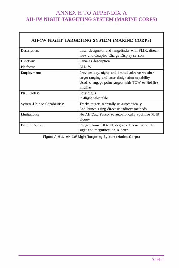
ANNEX H TO APPENDIX AAH-1W NIGHT TARGETING SYSTEM (MARINE CORPS)
A-H-1
Figure A-H-1. AH-1W Night Targeting System (Marine Corps)
AH-1W NIGHT TARGETING SYSTEM (MARINE CORPS)
Description: Laser designator and rangefinder with FLIR, direct-view and Coupled Charge Display sensors
Function: Same as description
Platform: AH-1W
Employment: Provides day, night, and limited adverse weathertarget ranging and laser designation capabilityUsed to engage point targets with TOW or Hellfiremissiles
PRF Codes: Four digitsIn-flight selectable
System-Unique Capabilities: Tracks targets manually or automaticallyCan launch using direct or indirect methods
Limitations: No Air Data Sensor to automatically optimize FLIRpicture
Field of View: Ranges from 1.0 to 30 degrees depending on thesight and magnification selected

A-H-2
Annex H to Appendix A
Joint Pub 3-09.1
Intentionally Blank
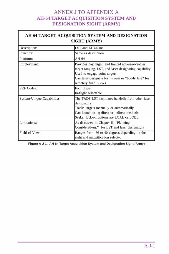
ANNEX J TO APPENDIX AAH-64 TARGET ACQUISITION SYSTEM AND
DESIGNATION SIGHT (ARMY)
A-J-1
Figure A-J-1. AH-64 Target Acquisition System and Designation Sight (Army)
AH-64 TARGET ACQUISITION SYSTEM AND DESIGNATIONSIGHT (ARMY)
Description: LST and LTD/Rand
Function: Same as description
Platform: AH-64
Employment: Provides day, night, and limited adverse-weathertarget ranging, LST, and laser-designating capabilityUsed to engage point targetsCan laser-designate for its own or “buddy lase” forremotely fired LGWs
PRF Codes: Four digitsIn-flight selectable
System-Unique Capabilities: The TADS LST facilitates handoffs from other laserdesignatorsTracks targets manually or automaticallyCan launch using direct or indirect methodsSeeker lock-on options are LOAL or LOBL
Limitations: As discussed in Chapter II, “PlanningConsiderations,” for LST and laser designators
Field of View: Ranges from .36 to 40 degrees depending on thesight and magnification selected

A-J-2
Annex J to Appendix A
Joint Pub 3-09.1
Intentionally Blank
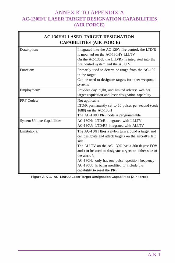
ANNEX K TO APPENDIX AAC-130H/U LASER TARGET DESIGNATION CAPABILITIES
(AIR FORCE)
A-K-1
Figure A-K-1. AC-130H/U Laser Target Designation Capabilities (Air Force)
AC-130H/U LASER TARGET DESIGNATION CAPABILITIES (AIR FORCE)
Description: Integrated into the AC-130’s fire control, the LTD/Ris mounted on the AC-130H’s LLLTVOn the AC-130U, the LTD/RF is integrated into thefire control system and the ALLTV
Function: Primarily used to determine range from the AC-130to the targetCan be used to designate targets for other weaponssystems
Employment: Provides day, night, and limited adverse weathertarget acquisition and laser designation capability
PRF Codes: Not applicableLTD/R permanently set to 10 pulses per second (code1688) on the AC-130HThe AC-130U PRF code is programmable
System-Unique Capabilities: AC-130H: LTD/R integrated with LLLTVAC-130U: LTD/RF integrated with ALLTV
Limitations: The AC-130H flies a pylon turn around a target andcan designate and attack targets on the aircraft’s leftsideThe ALLTV on the AC-130U has a 360 degree FOVand can be used to designate targets on either side ofthe aircraftAC-130H: only has one pulse repetition frequencyAC-130U: is being modified to include thecapability to reset the PRF

A-K-2
Annex K to Appendix A
Joint Pub 3-09.1
Intentionally Blank
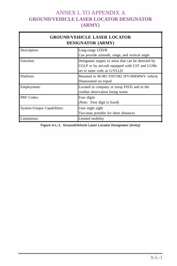
ANNEX L TO APPENDIX AGROUND/VEHICLE LASER LOCATOR DESIGNATOR
(ARMY)
A-L-1
Figure A-L-1. Ground/Vehicle Laser Locator Designator (Army)
GROUND/VEHICLE LASER LOCATORDESIGNATOR (ARMY)
Description: Long-range LTD/RCan provide azimuth, range, and vertical angle
Function: Designates targets or areas that can be detected byCGLP or by aircraft equipped with LST and LGMsset to same code as G/VLLD
Platform: Mounted in M-981 FIST/M2 IFV/HMMWV vehicleDismounted on tripod
Employment: Located in company or troop FISTs and in thecombat observation lasing teams
PRF Codes: Four digits(Note: First digit is fixed)
System-Unique Capabilities: Uses night sightTwo-man portable for short distances
Limitations: Limited mobility

A-L-2
Annex L to Appendix A
Joint Pub 3-09.1
Intentionally Blank
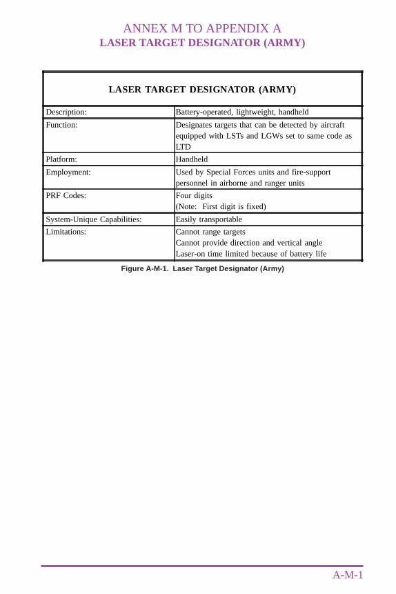
ANNEX M TO APPENDIX ALASER TARGET DESIGNATOR (ARMY)
A-M-1
Figure A-M-1. Laser Target Designator (Army)
LASER TARGET DESIGNATOR (ARMY)
Description: Battery-operated, lightweight, handheld
Function: Designates targets that can be detected by aircraftequipped with LSTs and LGWs set to same code asLTD
Platform: Handheld
Employment: Used by Special Forces units and fire-supportpersonnel in airborne and ranger units
PRF Codes: Four digits(Note: First digit is fixed)
System-Unique Capabilities: Easily transportable
Limitations: Cannot range targetsCannot provide direction and vertical angleLaser-on time limited because of battery life

A-M-2
Annex M to Appendix A
Joint Pub 3-09.1
Intentionally Blank
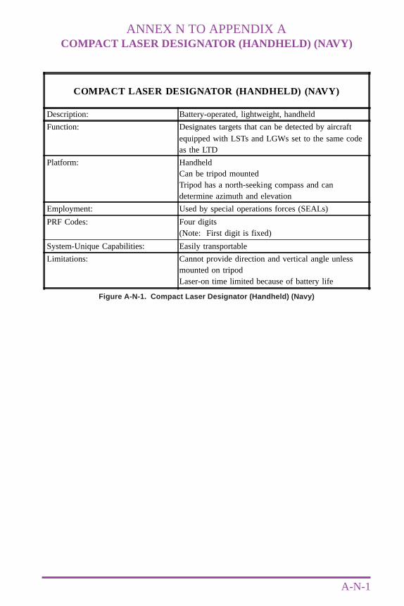
ANNEX N TO APPENDIX ACOMPACT LASER DESIGNATOR (HANDHELD) (NAVY)
A-N-1
Figure A-N-1. Compact Laser Designator (Handheld) (Navy)
COMPACT LASER DESIGNATOR (HANDHELD) (NAVY)
Description: Battery-operated, lightweight, handheld
Function: Designates targets that can be detected by aircraftequipped with LSTs and LGWs set to the same codeas the LTD
Platform: HandheldCan be tripod mountedTripod has a north-seeking compass and candetermine azimuth and elevation
Employment: Used by special operations forces (SEALs)
PRF Codes: Four digits(Note: First digit is fixed)
System-Unique Capabilities: Easily transportable
Limitations: Cannot provide direction and vertical angle unlessmounted on tripodLaser-on time limited because of battery life

A-N-2
Annex N to Appendix A
Joint Pub 3-09.1
Intentionally Blank
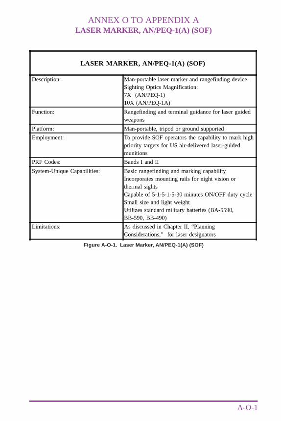
ANNEX O TO APPENDIX ALASER MARKER, AN/PEQ-1(A) (SOF)
A-O-1
Figure A-O-1. Laser Marker, AN/PEQ-1(A) (SOF)
LASER MARKER, AN/PEQ-1(A) (SOF)
Description: Man-portable laser marker and rangefinding device.Sighting Optics Magnification:7X (AN/PEQ-1)10X (AN/PEQ-1A)
Function: Rangefinding and terminal guidance for laser guidedweapons
Platform: Man-portable, tripod or ground supported
Employment: To provide SOF operators the capability to mark highpriority targets for US air-delivered laser-guidedmunitions
PRF Codes: Bands I and II
System-Unique Capabilities: Basic rangefinding and marking capabilityIncorporates mounting rails for night vision orthermal sightsCapable of 5-1-5-1-5-30 minutes ON/OFF duty cycleSmall size and light weightUtilizes standard military batteries (BA-5590,BB-590, BB-490)
Limitations: As discussed in Chapter II, “PlanningConsiderations,” for laser designators

A-O-2
Annex O to Appendix A
Joint Pub 3-09.1
Intentionally Blank
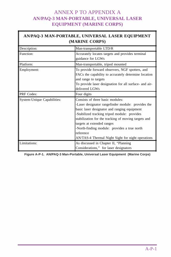
ANNEX P TO APPENDIX AAN/PAQ-3 MAN-PORTABLE, UNIVERSAL LASER
EQUIPMENT (MARINE CORPS)
A-P-1
Figure A-P-1. AN/PAQ-3 Man-Portable, Universal Laser Equipment (Marine Corps)
AN/PAQ-3 MAN-PORTABLE, UNIVERSAL LASER EQUIPMENT(MARINE CORPS)
Description: Man-transportable LTD/R
Function: Accurately locates targets and provides terminalguidance for LGWs
Platform: Man-transportable, tripod mounted
Employment: To provide forward observers, NGF spotters, andFACs the capability to accurately determine locationand range to targetsTo provide laser designation for all surface- and air-delivered LGWs
PRF Codes: Four digits
System-Unique Capabilities: Consists of three basic modules:-Laser designator rangefinder module: provides thebasic laser designator and ranging equipment-Stabilized tracking tripod module: providesstabilization for the tracking of moving targets andtargets at extended ranges-North-finding module: provides a true northreferenceAN/TAS-4 Thermal Night Sight for night operations
Limitations: As discussed in Chapter II, “PlanningConsiderations,” for laser designators

A-P-2
Annex P to Appendix A
Joint Pub 3-09.1
Intentionally Blank
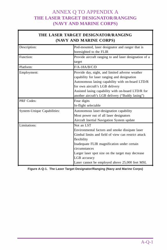
ANNEX Q TO APPENDIX ATHE LASER TARGET DESIGNATOR/RANGING
(NAVY AND MARINE CORPS)
A-Q-1
Figure A-Q-1. The Laser Target Designator/Ranging (Navy and Marine Corps)
THE LASER TARGET DESIGNATOR/RANGING(NAVY AND MARINE CORPS)
Description: Pod-mounted, laser designator and ranger that isboresighted to the FLIR
Function: Provide aircraft ranging to and laser designation of atarget
Platform: F/A-18A/B/C/D
Employment: Provide day, night, and limited adverse weathercapability for laser ranging and designationAutonomous lasing capability with on-board LTD/Rfor own aircraft’s LGB deliveryAssisted lasing capability with on-board LTD/R foranother aircraft’s LGB delivery (“Buddy lasing”)
PRF Codes: Four digitsIn-flight selectable
System-Unique Capabilities: Autonomous laser-designation capabilityMost power out of all laser designatorsAircraft Inertial Navigation System update
Limitations: Not an LSTEnvironmental factors and smoke dissipate laserGimbal limits and field of view can restrict attackflexibilityInadequate FLIR magnification under certaincircumstancesLarger laser spot size on the target may decreaseLGB accuracyLaser cannot be employed above 25,000 feet MSL

A-Q-2
Annex Q to Appendix A
Joint Pub 3-09.1
Intentionally Blank
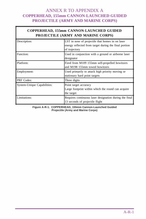
ANNEX R TO APPENDIX ACOPPERHEAD, 155mm CANNON-LAUNCHED GUIDED
PROJECTILE (ARMY AND MARINE CORPS)
A-R-1
Figure A-R-1. COPPERHEAD, 155mm Cannon-Launched GuidedProjectile (Army and Marine Corps)
COPPERHEAD, 155mm CANNON-LAUNCHED GUIDEDPROJECTILE (ARMY AND MARINE CORPS)
Description: LST in nose of projectile that homes in on laserenergy reflected from target during the final portionof trajectory
Function: Used in conjunction with a ground or airborne laserdesignator
Platform: Fired from M109 155mm self-propelled howitzersand M198 155mm towed howitzers
Employment: Used primarily to attack high priority moving orstationary hard point targets
PRF Codes: Three digits
System-Unique Capabilities: Point target accuracyLarge footprint within which the round can acquirethe target
Limitations: Requires continuous laser designation during the final13 seconds of projectile flight

A-R-2
Annex R to Appendix A
Joint Pub 3-09.1
Intentionally Blank
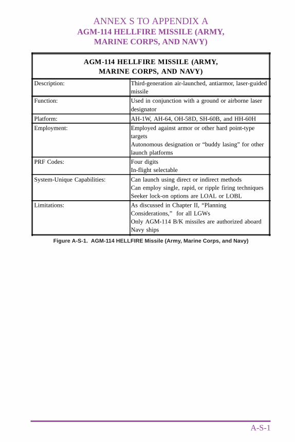
ANNEX S TO APPENDIX AAGM-114 HELLFIRE MISSILE (ARMY,
MARINE CORPS, AND NAVY)
A-S-1
Figure A-S-1. AGM-114 HELLFIRE Missile (Army, Marine Corps, and Navy)
AGM-114 HELLFIRE MISSILE (ARMY,MARINE CORPS, AND NAVY)
Description: Third-generation air-launched, antiarmor, laser-guidedmissile
Function: Used in conjunction with a ground or airborne laserdesignator
Platform: AH-1W, AH-64, OH-58D, SH-60B, and HH-60H
Employment: Employed against armor or other hard point-typetargetsAutonomous designation or “buddy lasing” for otherlaunch platforms
PRF Codes: Four digitsIn-flight selectable
System-Unique Capabilities: Can launch using direct or indirect methodsCan employ single, rapid, or ripple firing techniquesSeeker lock-on options are LOAL or LOBL
Limitations: As discussed in Chapter II, “PlanningConsiderations,” for all LGWsOnly AGM-114 B/K missiles are authorized aboardNavy ships

A-S-2
Annex S to Appendix A
Joint Pub 3-09.1
Intentionally Blank
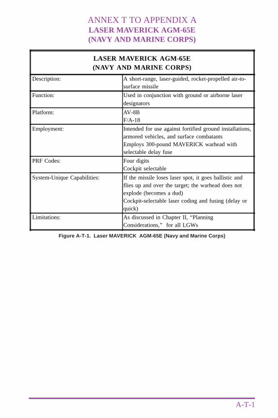
ANNEX T TO APPENDIX ALASER MAVERICK AGM-65E(NAVY AND MARINE CORPS)
A-T-1
Figure A-T-1. Laser MAVERICK AGM-65E (Navy and Marine Corps)
LASER MAVERICK AGM-65E(NAVY AND MARINE CORPS)
Description: A short-range, laser-guided, rocket-propelled air-to-surface missile
Function: Used in conjunction with ground or airborne laserdesignators
Platform: AV-8BF/A-18
Employment: Intended for use against fortified ground installations,armored vehicles, and surface combatantsEmploys 300-pound MAVERICK warhead withselectable delay fuse
PRF Codes: Four digitsCockpit selectable
System-Unique Capabilities: If the missile loses laser spot, it goes ballistic andflies up and over the target; the warhead does notexplode (becomes a dud)Cockpit-selectable laser coding and fusing (delay orquick)
Limitations: As discussed in Chapter II, “PlanningConsiderations,” for all LGWs

A-T-2
Annex T to Appendix A
Joint Pub 3-09.1
Intentionally Blank
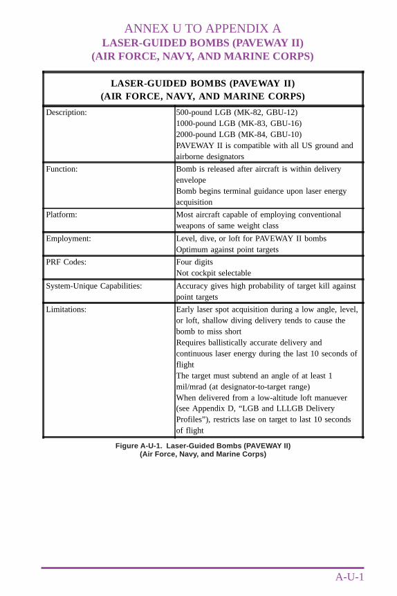
ANNEX U TO APPENDIX ALASER-GUIDED BOMBS (PAVEWAY II)
(AIR FORCE, NAVY, AND MARINE CORPS)
A-U-1
Figure A-U-1. Laser-Guided Bombs (PAVEWAY II)(Air Force, Navy, and Marine Corps)
LASER-GUIDED BOMBS (PAVEWAY II)(AIR FORCE, NAVY, AND MARINE CORPS)
Description: 500-pound LGB (MK-82, GBU-12)1000-pound LGB (MK-83, GBU-16)2000-pound LGB (MK-84, GBU-10)PAVEWAY II is compatible with all US ground andairborne designators
Function: Bomb is released after aircraft is within deliveryenvelopeBomb begins terminal guidance upon laser energyacquisition
Platform: Most aircraft capable of employing conventionalweapons of same weight class
Employment: Level, dive, or loft for PAVEWAY II bombsOptimum against point targets
PRF Codes: Four digitsNot cockpit selectable
System-Unique Capabilities: Accuracy gives high probability of target kill againstpoint targets
Limitations: Early laser spot acquisition during a low angle, level,or loft, shallow diving delivery tends to cause thebomb to miss shortRequires ballistically accurate delivery andcontinuous laser energy during the last 10 seconds offlightThe target must subtend an angle of at least 1mil/mrad (at designator-to-target range)When delivered from a low-altitude loft manuever(see Appendix D, “LGB and LLLGB DeliveryProfiles”), restricts lase on target to last 10 secondsof flight

A-U-2
Annex U to Appendix A
Joint Pub 3-09.1
Intentionally Blank
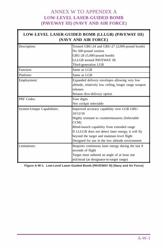
ANNEX W TO APPENDIX ALOW-LEVEL LASER-GUIDED BOMB
(PAVEWAY III) (NAVY AND AIR FORCE)
A-W-1
Figure A-W-1. Low-Level Laser-Guided Bomb (PAVEWAY III) (Navy and Air Force)
LOW-LEVEL LASER-GUIDED BOMB (LLLGB) (PAVEWAY III)(NAVY AND AIR FORCE)
Description: Termed GBU-24 and GBU-27 (2,000-pound bomb)No 500-pound versionGBU-28 (5,000-pound bomb)LLLGB termed PAVEWAY IIIThird-generation LGB
Function: Same as LGB
Platform: Same as LGB
Employment: Expanded delivery envelopes allowing very lowaltitude, relatively low ceiling, longer range weaponreleasesRetains dive-delivery option
PRF Codes: Four digitsNot cockpit selectable
System-Unique Capabilities: Improved accuracy capability over LGB GBU-10/12/16Highly resistant to countermeasures (SelectableCCM)Blind-launch capability from extended rangeIf LLLGB does not detect laser energy, it will flybeyond the target and maintain level flightDesigned for use in the low altitude environment
Limitations: Requires continuous laser energy during the last 8seconds of flightTarget must subtend an angle of at least onemil/mrad (at designator-to-target range)

A-W-2
Annex W to Appendix A
Joint Pub 3-09.1
Intentionally Blank
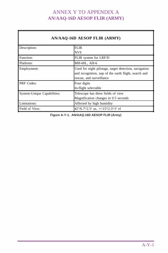
ANNEX Y TO APPENDIX AAN/AAQ-16D AESOP FLIR (ARMY)
A-Y-1
Figure A-Y-1. AN/AAQ-16D AESOP FLIR (Army)
AN/AAQ-16D AESOP FLIR (ARMY)
Description: FLIRNVS
Function: FLIR system for LRF/D
Platform: MH-60L, AH-6
Employment: Used for night pilotage, target detection, navigationand recognition, nap of the earth flight, search andrescue, and surveillance
PRF Codes: Four digitsIn-flight selectable
System-Unique Capabilities: Telescope has three fields of viewMagnification changes in 0.5 seconds
Limitations: Affected by high humidity
Field of View: 42o/6.7o/2.5o az, +/-15o/2.5o/1o el

A-Y-2
Annex Y to Appendix A
Joint Pub 3-09.1
Intentionally Blank
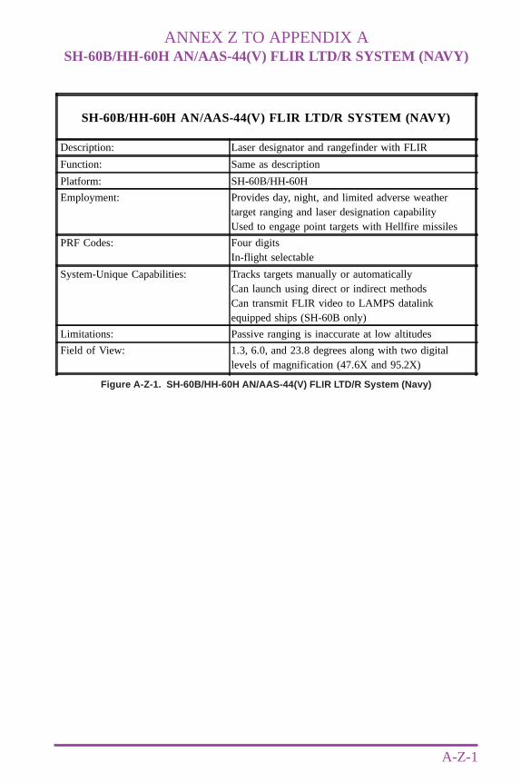
ANNEX Z TO APPENDIX ASH-60B/HH-60H AN/AAS-44(V) FLIR LTD/R SYSTEM (NAVY)
A-Z-1
Figure A-Z-1. SH-60B/HH-60H AN/AAS-44(V) FLIR LTD/R System (Navy)
SH-60B/HH-60H AN/AAS-44(V) FLIR LTD/R SYSTEM (NAVY)
Description: Laser designator and rangefinder with FLIR
Function: Same as description
Platform: SH-60B/HH-60H
Employment: Provides day, night, and limited adverse weathertarget ranging and laser designation capabilityUsed to engage point targets with Hellfire missiles
PRF Codes: Four digitsIn-flight selectable
System-Unique Capabilities: Tracks targets manually or automaticallyCan launch using direct or indirect methodsCan transmit FLIR video to LAMPS datalinkequipped ships (SH-60B only)
Limitations: Passive ranging is inaccurate at low altitudes
Field of View: 1.3, 6.0, and 23.8 degrees along with two digitallevels of magnification (47.6X and 95.2X)

A-Z-2
Annex Z to Appendix A
Joint Pub 3-09.1
Intentionally Blank

APPENDIX BPROCEDURES GUIDE
B-1
Annex A Ground and Airborne Laser Designation Procedures for theCLGP “COPPERHEAD”
B Ground and Airborne Laser Designation for CAS withFAC not Collocated with LDO or ALD
C Ground and Airborne Laser Designation Procedures forHelicopters

B-2
Appendix B
Joint Pub 3-09.1
Intentionally Blank
ANNEX A TO APPENDIX BGROUND AND AIRBORNE LASER DESIGNATIONPROCEDURES FOR THE CLGP “COPPERHEAD”
B-A-1
1. General
COPPERHEAD is a precision weapon with an observer-target range that is greater thanmaneuver direct fire weapons. Therefore, it is normally employed against target arrays whichare outside the range of direct fire systems. The successful use of COPPERHEAD requirescareful planning by the FSO and the observer, and detailed coordination between the observerand the firing unit. COPPERHEAD use is limited by the quantities available, battlefieldobscuration, cloud height, angle T, and effective range of the laser designator. COPPERHEADrequires uninterrupted LOS from the observer to the target and from the target to the roundduring the downward trajectory of flight.
2. Communications (See Figure B-A-1)
Communications between the observer and FDC occur using frequency modulation (FM),wire, mobile subscriber equipment, or tactical satellite. US Marine Corps units may use highfrequency radio.
3. Fire Mission Procedures
When observers acquire a target which is suitable for engaging with COPPERHEAD, theyinitiate a call for fire over the appropriate communications net to an artillery battery FDC.
a. Planned Targets
• When observers identify a stationary target at the planned target location, they initiatethe call for fire. If the target is moving towards the planned target location, observersinitiate the call for fire and place control of the unit at their command. Then observersmust use the target speed and the known or estimated firing unit response time andprojectile time of flight to determine when to issue the command to fire (trigger point).The call for fire is as follows:
ELEMENT EXAMPLE
Observer identification “R24, this is A58”Warning order “Fire target AF7005, over”Target description “4 tanks”Method of engagement “4 rounds”Method of control “At my command, over”
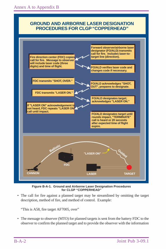
B-A-2
Annex A to Appendix B
Joint Pub 3-09.1
• The call for fire against a planned target may be streamlined by omitting the targetdescription, method of fire, and method of control. Example:
“This is A58, fire target AF7005, over”
• The message to observer (MTO) for planned targets is sent from the battery FDC to theobserver to confirm the planned target and to provide the observer with the information
GROUND AND AIRBORNE LASER DESIGNATIONPROCEDURES FOR CLGP“COPPERHEAD”
Forward observer/airborne laserdesignator (FO/ALD) transmitscall for fire. Includes laser-to-target line (direction).Fire direction center (FDC) copies
call for fire. Message to observerwill include laser code (threedigits) and time of flight. FO/ALD verifies laser code and
changes code if necessary.
FO/ALD acknowledges "SHOT,OUT", prepares to designate.
FO/ALD designates target;acknowledges "LASER ON."
FDC transmits "SHOT, OVER."
FDC transmits "LASER ON."
If "LASER ON" acknowledgement isnot heard, FDC repeats "LASER ON"call until impact.
FO/ALD designates target untilrounds impact, "TERMINATE"call is heard or 20 secondsafter expected time of flightexpire.
TARGETLASER
FDC
"LASER ON"Ballist
icGuided
CANNON
Figure B-A-1. Ground and Airborne Laser Designation Proceduresfor CLGP “COPPERHEAD”
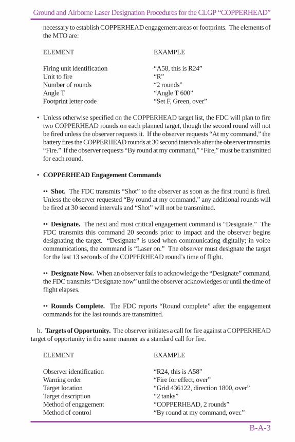
B-A-3
Ground and Airborne Laser Designation Procedures for the CLGP “COPPERHEAD”
necessary to establish COPPERHEAD engagement areas or footprints. The elements ofthe MTO are:
ELEMENT EXAMPLE
Firing unit identification “A58, this is R24”Unit to fire “R”Number of rounds “2 rounds”Angle T “Angle T 600”Footprint letter code “Set F, Green, over”
• Unless otherwise specified on the COPPERHEAD target list, the FDC will plan to firetwo COPPERHEAD rounds on each planned target, though the second round will notbe fired unless the observer requests it. If the observer requests “At my command,” thebattery fires the COPPERHEAD rounds at 30 second intervals after the observer transmits“Fire.” If the observer requests “By round at my command,” “Fire,” must be transmittedfor each round.
• COPPERHEAD Engagement Commands
•• Shot. The FDC transmits “Shot” to the observer as soon as the first round is fired.Unless the observer requested “By round at my command,” any additional rounds willbe fired at 30 second intervals and “Shot” will not be transmitted.
•• Designate. The next and most critical engagement command is “Designate.” TheFDC transmits this command 20 seconds prior to impact and the observer beginsdesignating the target. “Designate” is used when communicating digitally; in voicecommunications, the command is “Laser on.” The observer must designate the targetfor the last 13 seconds of the COPPERHEAD round’s time of flight.
•• Designate Now. When an observer fails to acknowledge the “Designate” command,the FDC transmits “Designate now” until the observer acknowledges or until the time offlight elapses.
•• Rounds Complete. The FDC reports “Round complete” after the engagementcommands for the last rounds are transmitted.
b. Targets of Opportunity. The observer initiates a call for fire against a COPPERHEADtarget of opportunity in the same manner as a standard call for fire.
ELEMENT EXAMPLE
Observer identification “R24, this is A58”Warning order “Fire for effect, over”Target location “Grid 436122, direction 1800, over”Target description “2 tanks”Method of engagement “COPPERHEAD, 2 rounds”Method of control “By round at my command, over.”
B-A-4
Annex A to Appendix B
Joint Pub 3-09.1
MTO ELEMENT EXAMPLE
Unit firing “R”Target number “AF7006”Number of rounds “2 rounds”Laser PRF code “code 241”Time of flight “Time of flight, 25, over”
The PRF code transmitted by the FDC in the MTO is a confirmation of the PRF code assignedto the observer by the FSO. If the PRF code in the MTO is different than the observer’s pre-assigned code, the observer must change the code on the laser designator before receiving the“Laser on” command.
ANNEX B TO APPENDIX BGROUND AND AIRBORNE LASER DESIGNATION FOR CAS
WITH FAC NOT COLLOCATED WITH LDO OR ALD
B-B-1
1. Communications (See Figure B-B-1)
a. Communications between LDO or ALD and FAC, if not collocated: FM.
b. Communications between FAC and aircraft: FM, ultra high frequency (UHF), or veryhigh frequency (VHF).
c. Communications between LDO or ALD and aircraft: FM, (UHF or VHF when available).
2. Additions to Tactical Air Request
a. Laser Code. (FAC gets laser code from the FSO or FSCC and passes to aircraft withLST. FAC obtains or passes laser code to FSO or FSCC for attacking aircraft with LGWs.)
b. Request for LGWs.
c. Laser-to-target line in degrees magnetic.
d. Radio frequency and call sign for final controller to whom pilot will give final attacklaser calls.
3. Additions to FAC to Aircrew CAS Briefing (Appendix C, “CASBriefing Form [9-Line]”)
a. Request laser code, four digits (lxxx) set in LGWs on aircraft. In the case of LGMequipped aircraft, the FAC will pass the laser code set in the ground designator, and the LGMseeker codes will be changed to match the ground designator or ALD.
b. Pass laser-to-target line in degrees magnetic.
c. Laser-spot offset information, if applicable.
d. Pass radio frequency and call sign for final controller to whom aircrew will give finalattack laser calls.
4. Additions to Aircrew to FAC Reporting Procedures
a. Pass that LGWs are to be delivered and the laser codes set in them.
b. “10 SECONDS” warning call that aircraft will need laser on in 10 seconds.
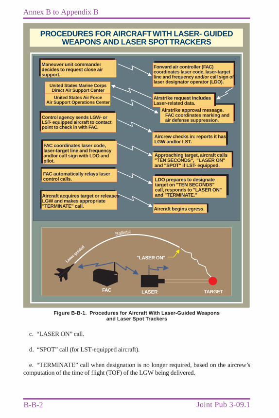
B-B-2
Annex B to Appendix B
Joint Pub 3-09.1
c. “LASER ON” call.
d. “SPOT” call (for LST-equipped aircraft).
e. “TERMINATE” call when designation is no longer required, based on the aircrew’scomputation of the time of flight (TOF) of the LGW being delivered.
PROCEDURES FOR AIRCRAFT WITH LASER- GUIDEDWEAPONS AND LASER SPOTTRACKERS
Forward air controller (FAC)coordinates laser code, laser-targetline and frequency and/or call sign oflaser designator operator (LDO).
Maneuver unit commanderdecides to request close airsupport.
Airstrike approval message.FAC coordinates marking andair defense suppression.
Aircrew checks in: reports it hasLGW and/or LST.
Aircraft begins egress.
Approaching target, aircraft calls"TEN SECONDS", "LASER ON"and "SPOT" if LST- equipped.
United States Marine CorpsDirect Air Support Center
United States Air ForceAir Support Operations Center
Control agency sends LGW- orLST- equipped aircraft to contactpoint to check in with FAC.
FAC coordinates laser code,laser-target line and frequencyand/or call sign with LDO andpilot.
Aircraft acquires target or releasesLGW and makes appropriate"TERMINATE" call.
FAC automatically relays lasercontrol calls. LDO prepares to designate
target on "TEN SECONDS"call, responds to "LASER ON"and "TERMINATE."
TARGETLASERFAC
"LASER ON"
Ballistic
Lase
r-guid
ed
Airstrike request includesLaser-related data.
Figure B-B-1. Procedures for Aircraft With Laser-Guided Weaponsand Laser Spot Trackers

B-B-3
Ground and Airborne Laser Designation for CAS with FAC Not Collocated with LDO or ALD
5. Additions to FAC to LDO or ALD Calls
a. Confirm LST- and LGW-equipped aircraft inbound.
b. Confirm laser code to be used. Ground LDOs and ALDs will change to codes set inLGWs carried by supporting aircraft.
c. FAC automatically relays all laser calls from aircrew to LDO or ALD.

B-B-4
Annex B to Appendix B
Joint Pub 3-09.1
Intentionally Blank
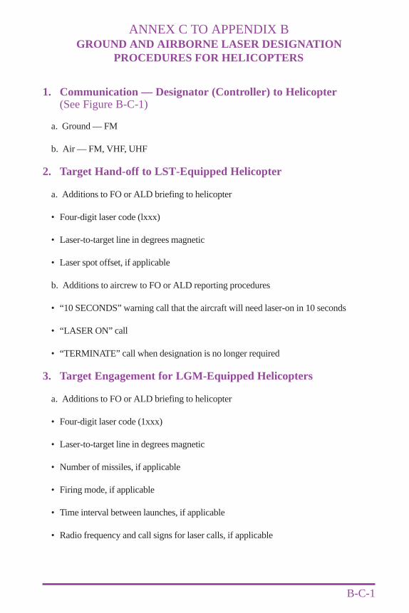
ANNEX C TO APPENDIX BGROUND AND AIRBORNE LASER DESIGNATION
PROCEDURES FOR HELICOPTERS
B-C-1
1. Communication — Designator (Controller) to Helicopter(See Figure B-C-1)
a. Ground — FM
b. Air — FM, VHF, UHF
2. Target Hand-off to LST-Equipped Helicopter
a. Additions to FO or ALD briefing to helicopter
• Four-digit laser code (lxxx)
• Laser-to-target line in degrees magnetic
• Laser spot offset, if applicable
b. Additions to aircrew to FO or ALD reporting procedures
• “10 SECONDS” warning call that the aircraft will need laser-on in 10 seconds
• “LASER ON” call
• “TERMINATE” call when designation is no longer required
3. Target Engagement for LGM-Equipped Helicopters
a. Additions to FO or ALD briefing to helicopter
• Four-digit laser code (1xxx)
• Laser-to-target line in degrees magnetic
• Number of missiles, if applicable
• Firing mode, if applicable
• Time interval between launches, if applicable
• Radio frequency and call signs for laser calls, if applicable
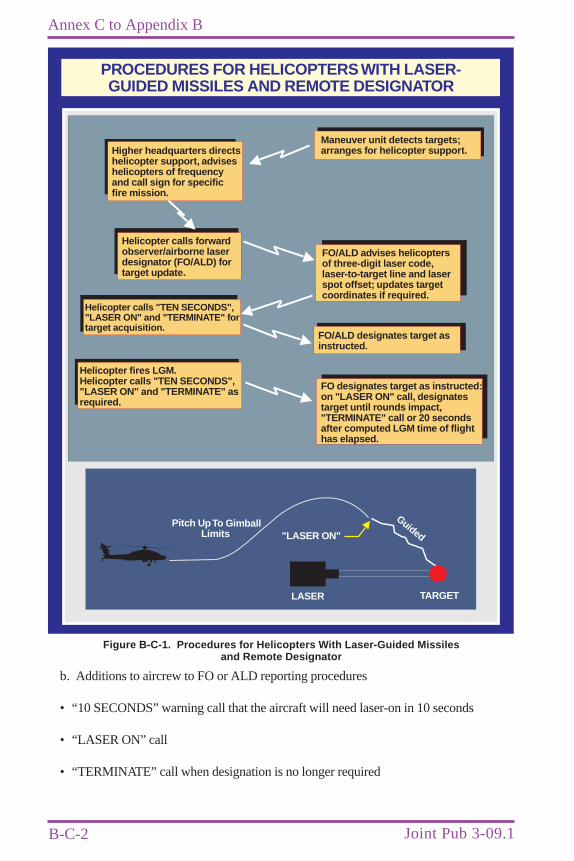
B-C-2
Annex C to Appendix B
Joint Pub 3-09.1
b. Additions to aircrew to FO or ALD reporting procedures
• “10 SECONDS” warning call that the aircraft will need laser-on in 10 seconds
• “LASER ON” call
• “TERMINATE” call when designation is no longer required
PROCEDURES FOR HELICOPTERSWITH LASER-GUIDED MISSILES AND REMOTE DESIGNATOR
Maneuver unit detects targets;arranges for helicopter support.Higher headquarters directs
helicopter support, adviseshelicopters of frequencyand call sign for specificfire mission.
Helicopter calls forwardobserver/airborne laserdesignator (FO/ALD) fortarget update.
FO/ALD advises helicoptersof three-digit laser code,laser-to-target line and laserspot offset; updates targetcoordinates if required.
Helicopter calls "TEN SECONDS","LASER ON" and "TERMINATE" fortarget acquisition.
FO designates target as instructed:on "LASER ON" call, designatestarget until rounds impact,"TERMINATE" call or 20 secondsafter computed LGM time of flighthas elapsed.
Helicopter fires LGM.Helicopter calls "TEN SECONDS","LASER ON" and "TERMINATE" asrequired.
FO/ALD designates target asinstructed.
TARGETLASER
"LASER ON"Pitch UpTo Gimball
Limits
Guided
Figure B-C-1. Procedures for Helicopters With Laser-Guided Missilesand Remote Designator
B-C-3
Ground and Airborne Laser Designation Procedures for Helicopters
NOTE: Army FM 1-112 should be reviewed for more specific AH-64/OH-58D engagementprocedures.
4. HELLFIRE Guided Missile Surface Danger Zone
a. A HELLFIRE guided missile is an air-launched antiarmor weapon launched from theAH-64, AH-1, and OH-58D. HELLFIRE homes in on a laser spot projected from either aground observer, another aircraft, or the launch aircraft itself. The AH-64 can engage targetsautonomously or work as a team member. As many as 10 targets can be handed off to theAH-64, providing rapid target engagement. The following operational modes can be selectedwhen firing HELLFIRE.
• Lock-On After Launch (Direct Launch Mode). An LOS exists between theHELLFIRE missile and the target; however, HELLFIRE seeker lock-on is inhibited bydistance. HELLFIRE is launched in the general direction of the target, locks-on afterlaunch, and then homes to the target.
• Lock-On Before Launch (Direct Launch Mode). The HELLFIRE missile seekertracks the target prior to launch. Once launched, the missile homes to the target.
• Lock-On After Launch (Indirect Launch Mode). The HELLFIRE missile is launchedfrom behind a terrain mask or in defilade. The missile seeker then acquires the target andhomes in on a preselected trajectory.
b. Surface danger zones for a direct launch and indirect launch provide for all firing modesof the HELLFIRE missile at fixed targets to include the effects of the warhead functioning atthe edge of the impact area. No specific warhead area is included because the HELLFIREmissile system has no practice warhead.
c. All laser range control procedures and laser surface danger zone parameters outlined inAR 385-63, Chapter 19, apply to designators being used with the HELLFIRE missile (alsosee TB MED 524). Because of the large surface danger zones and the limited range of thedesignators, it may be necessary to place designator operators within the surface dangerzones during some training exercises. Three designator zones for designator operators havebeen established within the surface danger zones. These designator zones and their specificrange requirements are provided below.
• Prohibited Designator Zone. No designator operators are allowed in this zone becauseof the unacceptable probabilities associated with the following hazards:
•• There are remote scenarios where the missile seeker can track the laser backscatterenergy at the exit aperture of the designator or along the path of the laser beam; and
•• The probability of random missile failures is the highest within this zone.
B-C-4
Annex C to Appendix B
Joint Pub 3-09.1
• Protected Designator Zone. Designator operators are not vulnerable to a normallyfunctioning missile tracking the laser backscatter energy in this zone. However, there isa possibility that the missile may track and impact an obstruction (e.g., trees, grass, hills)near the designator operator if it is accidentally illuminated by the laser beam. Thepossibility of being injured by a random missile failure impacting within 150 meters ofa designator operator in this area is less than 4 in 10 million.
•• Ground-designator operators will wear flak jackets and military issue helmets and belocated in protected positions (e.g., sand bags enclosing the designator operator).
•• The designator will have a clear unobstructed LOS to the target. All obstacles (e.g.,trees, rocks, grass) should be at least 500 meters from the laser beam. Special careshould be taken to ensure that designator LOS is unobstructed across the entire path of amoving target during the TOF to impact.
•• Ground-designator operators must ensure that they do not inadvertently lase throughdust caused by other personnel, vehicles.
•• Airborne designators must ensure that they are either over ground conditions that donot create dust or at an altitude where rotor downwash does not create dust.
•• In peacetime operations, both ground and airborne designators may occupy theprotected designator zone when formal justification is provided and a waiver grantedIAW the provisions of AR 385-62, Chapter 1 (Formal waivers are usually already ineffect for wartime operations). Waivers should be granted when there is no possible wayto conduct operations in the unprotected designator zone or outside the surface dangerzone(s).
• Unprotected Designator Zone. Although designator operators are not vulnerable to anormally functioning missile tracking the backscatter or false targets in this zone, thereis still a possibility of a random missile failure. The probability of a random missilefailure impacting with 150 meters of the designator is smaller in this zone than in theprotected designator zone.
•• At a minimum, ground designator operators should wear flak jackets and militaryhelmets.
•• The requirements of subparagraphs 4c above also apply to the unprotected designatorzone.
•• Designator operations (ground and/or airborne) may be conducted in the unprotecteddesignator zone when formal justification is provided and a waiver granted IAW theprovisions of AR 385-62, Chapter 1.
d. Two additional areas within the surface danger zones are as follows.
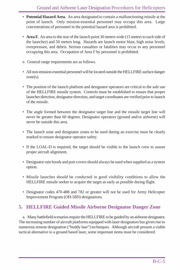
B-C-5
Ground and Airborne Laser Designation Procedures for Helicopters
• Potential Hazard Area. An area designated to contain a malfunctioning missile at thepoint of launch. Only mission-essential personnel may occupy this area. Largeconcentrations of personnel in the potential hazard area is prohibited.
• Area F. An area to the rear of the launch point 30 meters wide (15 meters to each side ofthe launcher) and 50 meters long. Hazards are launch motor blast, high noise levels,overpressure, and debris. Serious casualties or fatalities may occur to any personneloccupying this area. Occupation of Area F by personnel is prohibited.
e. General range requirements are as follows.
• All non-mission-essential personnel will be located outside the HELLFIRE surface dangerzone(s).
• The position of the launch platform and designator operators are critical to the safe useof the HELLFIRE missile system. Controls must be established to ensure that properlauncher direction, designator direction, and target coordinates are verified prior to launchof the missile.
• The angle formed between the designator target line and the missile target line willnever be greater than 60 degrees. Designator operators (ground and/or airborne) willnever be outside this area.
• The launch zone and designator zones to be used during an exercise must be clearlymarked to ensure designator operator safety.
• If the LOAL-D is required, the target should be visible to the launch crew to assureproper aircraft alignment.
• Designator rain hoods and port covers should always be used when supplied as a systemoption.
• Missile launches should be conducted in good visibility conditions to allow theHELLFIRE missile seeker to acquire the target as early as possible during flight.
• Designator codes 470-488 and 782 or greater will not be used for Army HelicopterImprovement Program (OH-58D) designations.
5. HELLFIRE Guided Missile Airborne Designator Danger Zone
a. Many battlefield scenarios require the HELLFIRE to be guided by an airborne designator.The increasing number of aircraft platforms equipped with laser designators has given rise tonumerous remote designation (“buddy lase”) techniques. Although aircraft present a viabletactical alternative to a ground based laser, some important items must be considered.
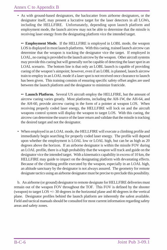
B-C-6
Annex C to Appendix B
Joint Pub 3-09.1
• As with ground-based designators, the backscatter from airborne designators, or thedesignator itself, may present a lucrative target for the laser detectors in all LGWs,including the HELLFIRE. Unfortunately, depending upon launch platform andemployment mode, the launch aircrew may not be able to determine that the missile isreceiving laser energy from the designating platform vice the intended target.
•• Employment Mode. If the HELLFIRE is employed in LOBL mode, the weaponLOS is displayed in most launch platforms. With this cueing, trained launch aircrew candetermine that the weapon is tracking the designator vice the target. If employed inLOAL, no cueing is provided to the launch aircrew by the weapon. Other aircraft systemsmay provide this cueing but will generally not be capable of detecting the laser spot in anLOAL scenario. The bottom line is that only an LOBL launch is capable of providingcueing of the weapon’s aimpoint; however, even if an LOBL is planned, launch aircrewtrain to employ in an LOAL mode if a laser spot is not received once clearance to launchhas been given. This training consists of ensuring specific safety offset angles are usedbetween the launch platform and the designator to minimize fratricide.
•• Launch Platform. Several US aircraft employ the HELLFIRE, but the amount ofaircrew cueing varies greatly. Most platforms, including the AH-1W, the AH-64, andthe AH-60, provide aircrew cueing in the form of a pointer at weapon LOS. Whenreceiving properly coded laser energy, the HELLFIRE will lock on and the aircraftweapons control system will display the weapon to target LOS. With this cueing, theaircrew can determine the source of the laser return and validate that the missile is trackingthe desired target and not the designator.
• When employed in an LOAL mode, the HELLFIRE will execute a climbing profile andimmediately begin searching for properly coded laser energy. The profile will dependupon whether the employment is LOAL low or LOAL high, but can be as high as 20degrees above the horizon. If an airborne designator is within the missile FOV duringan LOAL profile, there is a high probability that the weapon will track and guide on thedesignator vice the intended target. With a kinematics capability in excess of 10 km, theHELLFIRE may guide to impact on the designating platform with devastating effects.Because of the climbing profile executed by the weapon, especially in an LOAL high,an altitude sanctuary by the designator is not always assured. The geometry for remotedesignate tactics using an airborne designator must be precise to preclude this possibility.
b. An airborne (or ground) designator to remote designate for HELLFIRE deliveries mustremain out of the weapon FOV throughout the TOF. This FOV is defined by the shooter(weapon) to target LOS +/- 30 degrees in the horizontal plane and 40 degrees in the verticalplane. Designator profiles behind the launch platform are inherently the safest available.Field and tactical manuals should be consulted for most current information regarding safetyareas and safety zones.

APPENDIX CCAS BRIEFING FORM (9-LINE)
C-1
(Omit data not required, do not transmit line numbers. Units of measure are standard unlessotherwise specified. * denotes minimum essential in limited communications environment.Bold denotes readback items when requested.)
Terminal controller: “___________________, this is __________________________”(aircraft call sign) (terminal controller)
*1. IP/BP: “___________________________________________________”
*2. Heading: “_____________________________________” (magnetic).(IP/BP to target)
Offset: “_____________________________________ (left/right)”
*3. Distance: “________________________________________________”(IP to target in nautical miles/BP to target in meters)
*4. Target elevation: “__________________________” (in feet MSL)
*5. Target description: “_______________________________________”
*6. Target location: “_________________________________________”(latitude/longitude or grid coordinates or offsets or visual)
*7. Type mark: “_______________________” Code: “_______________”(WP, laser, IR, beacon) (actual code)
Laser to target line: “_______________” (degrees)
*8. Location of friendlies: “_________________________________”Position marked by: “____________________________”
*9. Egress: “______________________________________”In the event of a beacon bombing request, insert beacon bombingchart line numbers here.__________________________________________________________
Remarks (As appropriate): “_____________________________________”(threats, restrictions, danger close, attack clearance, SEAD, abort codes, hazards)
NOTE: For AC-130 employment, lines 5, 6, and 8 are mandatory briefing items. Remarksshould also include detailed threat description, marking method of friendly locations (includingmagnetic bearing and distance in meters from the friendly position to the target, if available),identifiable ground features, danger close acceptance.

C-2
Appendix C
Joint Pub 3-09.1
Time on target: “______________________________”
OR
Time to target: “Stand by _______ plus _______, Hack.”
Refer to JP 3-09.3, “Joint Tactics, Techniques, and Procedures for Close Air Support (CAS).”This format varies slightly from NATO-approved procedures published in ACP 125, Supplement2(A).
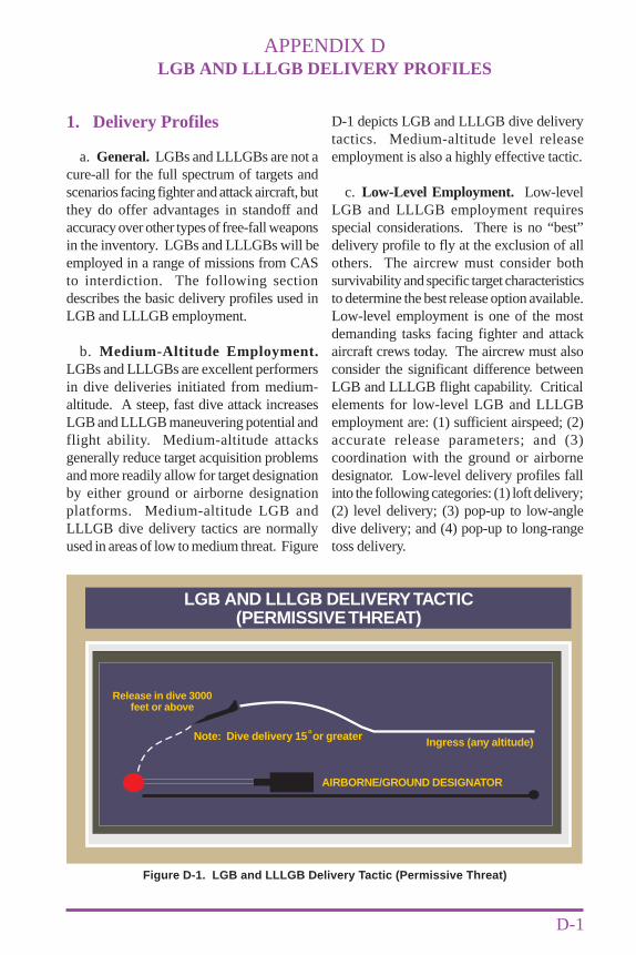
APPENDIX DLGB AND LLLGB DELIVERY PROFILES
D-1
1. Delivery Profiles
a. General. LGBs and LLLGBs are not acure-all for the full spectrum of targets andscenarios facing fighter and attack aircraft, butthey do offer advantages in standoff andaccuracy over other types of free-fall weaponsin the inventory. LGBs and LLLGBs will beemployed in a range of missions from CASto interdiction. The following sectiondescribes the basic delivery profiles used inLGB and LLLGB employment.
b. Medium-Altitude Employment.LGBs and LLLGBs are excellent performersin dive deliveries initiated from medium-altitude. A steep, fast dive attack increasesLGB and LLLGB maneuvering potential andflight ability. Medium-altitude attacksgenerally reduce target acquisition problemsand more readily allow for target designationby either ground or airborne designationplatforms. Medium-altitude LGB andLLLGB dive delivery tactics are normallyused in areas of low to medium threat. Figure
D-1 depicts LGB and LLLGB dive deliverytactics. Medium-altitude level releaseemployment is also a highly effective tactic.
c. Low-Level Employment. Low-levelLGB and LLLGB employment requiresspecial considerations. There is no “best”delivery profile to fly at the exclusion of allothers. The aircrew must consider bothsurvivability and specific target characteristicsto determine the best release option available.Low-level employment is one of the mostdemanding tasks facing fighter and attackaircraft crews today. The aircrew must alsoconsider the significant difference betweenLGB and LLLGB flight capability. Criticalelements for low-level LGB and LLLGBemployment are: (1) sufficient airspeed; (2)accurate release parameters; and (3)coordination with the ground or airbornedesignator. Low-level delivery profiles fallinto the following categories: (1) loft delivery;(2) level delivery; (3) pop-up to low-angledive delivery; and (4) pop-up to long-rangetoss delivery.
LGB AND LLLGB DELIVERYTACTIC(PERMISSIVETHREAT)
AIRBORNE/GROUND DESIGNATOR
Note: Dive delivery 15 or greatero
Release in dive 3000feet or above
Ingress (any altitude)
Figure D-1. LGB and LLLGB Delivery Tactic (Permissive Threat)
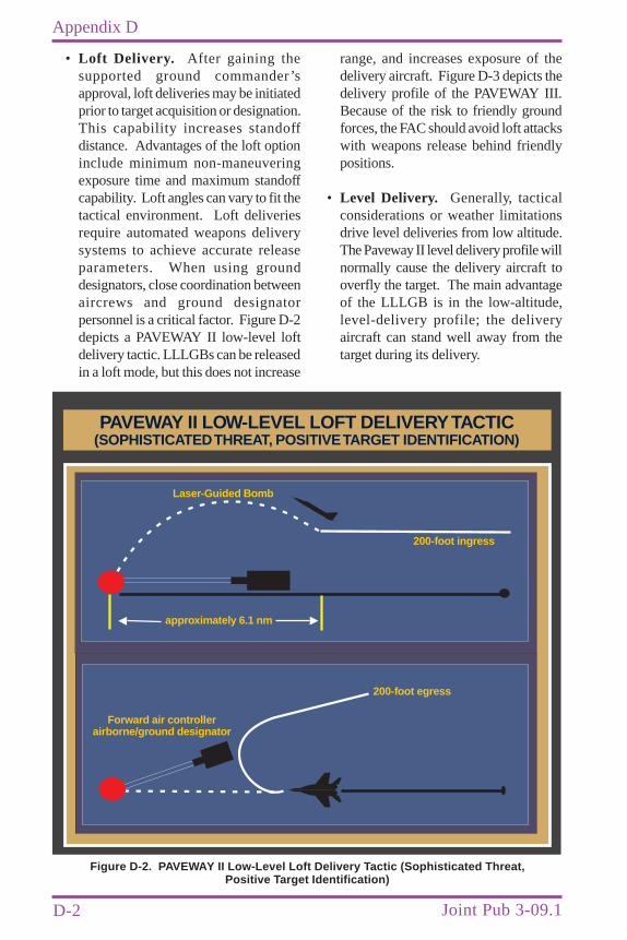
D-2
Appendix D
Joint Pub 3-09.1
• Loft Delivery. After gaining thesupported ground commander’sapproval, loft deliveries may be initiatedprior to target acquisition or designation.This capability increases standoffdistance. Advantages of the loft optioninclude minimum non-maneuveringexposure time and maximum standoffcapability. Loft angles can vary to fit thetactical environment. Loft deliveriesrequire automated weapons deliverysystems to achieve accurate releaseparameters. When using grounddesignators, close coordination betweenaircrews and ground designatorpersonnel is a critical factor. Figure D-2depicts a PAVEWAY II low-level loftdelivery tactic. LLLGBs can be releasedin a loft mode, but this does not increase
range, and increases exposure of thedelivery aircraft. Figure D-3 depicts thedelivery profile of the PAVEWAY III.Because of the risk to friendly groundforces, the FAC should avoid loft attackswith weapons release behind friendlypositions.
• Level Delivery. Generally, tacticalconsiderations or weather limitationsdrive level deliveries from low altitude.The Paveway II level delivery profile willnormally cause the delivery aircraft tooverfly the target. The main advantageof the LLLGB is in the low-altitude,level-delivery profile; the deliveryaircraft can stand well away from thetarget during its delivery.
PAVEWAY II LOW-LEVEL LOFT DELIVERYTACTIC(SOPHISTICATEDTHREAT, POSITIVETARGET IDENTIFICATION)
200-foot ingress
200-foot egress
Forward air controllerairborne/ground designator
approximately 6.1 nm
Laser-Guided Bomb
Figure D-2. PAVEWAY II Low-Level Loft Delivery Tactic (Sophisticated Threat,Positive Target Identification)
D-3
LGB and LLLGB Delivery Profiles
PAVEWAY III LOW-LEVEL DELIVERYTACTIC
200-foot ingress
approximately 6.1 nm
Paveway III
Figure D-3. PAVEWAY III Low-Level Delivery Tactic
• Pop-up to Low-Angle Dive Delivery.Pop-up to low-angle dive deliveries offeradvantages over level releases. Targetacquisition is easier with level deliverybecause the apex is higher, there is moretime available for search, and the bombhas better maneuverability. Exposure isusually longer than for a level approach,so the aircrew should maneuver theaircraft throughout the delivery. FigureD-4 depicts the LGB and LLLGB pop-up delivery tactic.
• Pop-up to Long-Range Toss Delivery.Toss deliveries provide increaseddelivery flexibility over other deliveryoptions; however, they are not normallyused in the CAS arena. While ceilingand visibility may dictate releaseparameters, standoff capability is verygood and varies with the type of weaponused and the release altitude which maybe restricted by ceiling and visibility.Total exposure time is moderate and non-maneuvering exposure time isminimized. The toss delivery profile isvery similar to that illustrated for the loftin Figure D-2.
d. LLLGB Advantages. The LLLGB wasdeveloped in response to sophisticated enemyair defenses and poor visibility and to counterlimitations in low ceilings. The weapon isdesigned for low-altitude delivery and with acapability for improved standoff ranges toreduce exposure. Unlike the LGB, theLLLGB can correct for relatively largedeviations from planned release parametersin the primary delivery mode (low-altitude,level-delivery). It also has a larger deliveryenvelope for the dive, glide, and loft modesthan does the earlier LGB. The wide field ofview and midcourse guidance modesprogrammed in the LLLGB allow for a “pointand shoot” delivery capability that allows theaircrew to attack the target by pointing theaircraft at the target and releasing the weaponafter obtaining appropriate sight indications.The primary advantage of this capability isthat accurate diving or tracking is not requiredto solve wind-drift problems. An addedadvantage of the LLLGB in a CAS situationis that if the LLLGB does not detect reflectedlaser energy, it will maintain level flight tocontinue beyond the designated target,overflying friendly positions to impact longrather than short of the target.
D-4
Appendix D
Joint Pub 3-09.1
LGB AND LLLGB POP-UP DELIVERYTACTIC(SOPHISTICATEDTHREAT,TARGET IDENTIFICATION DIFFICULT)
Pop-up to 1000 to 3000 feet200-foot ingress
Note: Delivery can be levelor shallow dive (ca. 10 ) O
Airborne and/or ground designator
descend to 200 feet foregress
LASER
approximately 4.6 km
Figure D-4. LGB and LLLGB Pop-Up Delivery Tactic (Sophisticated Threat,Target Identification Difficult)
APPENDIX ELASER PROTOCOL
E-1
1. General
a. The “Laser Protocol to the 1994 Convention on Prohibitions or Restrictions on the Useof Certain Conventional Weapons Which May Be Deemed to be Excessively Injurious or toHave Indiscriminate Effects” was only recently negotiated. It deals with a subject aboutwhich there is neither existing conventional (treaty) law nor customary international practice.The United States has not yet ratified the Protocol. The Protocol has no binding effect on theUnited States or its military personnel.
b. Even if the Laser Protocol did have a binding effect, it does not prohibit the use of thelasers described in this publication because none of them are designed to cause blindness asa combat function. Rather, each is designed for target designation, range finding, and otherrelated areas. Incidental or collateral blindness caused by a legitimate military laser is notprohibited by the Protocol (Article 3).
c. The Secretary of Defense memorandum in Paragraph 3 is an effective constraint on USforces. It also only prohibits lasers designed to cause permanent blindness, and recognizestargeting and range-finding lasers as permissible.
2. Protocol Terms
The terms of the Laser Protocol are as follows.
ADDITIONAL PROTOCOL TO THE CONVENTION ON PROHIBITIONS ORRESTRICTIONS ON THE USE OF CERTAIN CONVENTIONAL WEAPONS
WHICH MAY BE DEEMED TO BE EXCESSIVELY INJURIOUSOR TO HAVE INDISCRIMINATE EFFECTS
ARTICLE 1: ADDITIONAL PROTOCOL
The following protocol shall be annexed to the Convention on Prohibitions or Restrictionson the Use of Certain Conventional Weapons Which May Be Deemed to Be ExcessivelyInjurious or to Have Indiscriminate Effects (“the Convention”) as Protocol IV:
“Protocol on Blinding Laser Weapons”(Protocol IV)
Article 1:
It is prohibited to employ laser weapons specifically designed, as their sole combatfunction or as one of their combat functions, to cause permanent blindness to unenhancedvision, that is to the naked eye or to the eye with corrective eyesight devices. The HighContracting Parties shall not transfer such weapons to any State or non-State entity.
E-2
Appendix E
Joint Pub 3-09.1
Article 2:
In the employment of laser systems, the High Contracting Parties shall take all feasibleprecautions to avoid the incidence of permanent blindness to unenhanced vision. Suchprecautions shall include training of their armed forces and other practical measures.
Article 3:
Blindness as an incidental or collateral effect of the legitimate military employment oflaser systems, including laser systems used against optical equipment, is not covered bythe prohibitions of this Protocol.
Article 4:
For the purpose of this Protocol ‘permanent blindness’ means irreversible anduncorrectable loss of vision which is seriously disabling with no prospect of recovery.Serious disability is equivalent to visual acuity of less than 20/200 Snellen measuredusing both eyes.
ARTICLE 2: ENTRY INTO FORCE
This Protocol shall enter into force as provided in paragraphs 3 and 4 of Article 5 of theConvention.
CCW Conference: Vienna, Austria 199525 September - 13 October 1995
3. DOD Policy on Blinding Lasers
The following is the current DOD policy on the use of blinding lasers.
DOD Policy on Blinding Lasers
The Department of Defense prohibits the use of lasers specifically designed to causepermanent blindness and supports negotiations prohibiting the use of such weapons.However, laser systems are absolutely vital to our modern military. Among other things,they are currently used for detection, targeting, range-finding, communications and targetdestruction. They provide a critical technological edge to US forces and allow ourforces to fight, win and survive on an increasingly lethal battlefield. In addition, lasersprovide significant humanitarian benefits. They allow weapon systems to be increasinglydiscriminate, thereby reducing collateral damage to civilian lives and property. TheDepartment of Defense recognizes that accidental or incidental eye injuries may occur

E-3
Laser Protocol
on the battlefield as the result of the use of lasers not specifically designed to causepermanent blindness. Therefore, we continue to strive, through training and doctrine, tominimize these injuries.
Secretary of Defense William J. PerryJanuary 17, 1997
Current DOD Policy on Blinding Lasers

E-4
Appendix E
Joint Pub 3-09.1
Intentionally Blank
APPENDIX FREFERENCES
F-1
The development of Joint Pub 3-09.1 is based upon the following primary references.
1. Joint Publications
a. Joint Pub 1-02, “DOD Dictionary of Military and Associated Terms.”
b. Joint Pub 3-0, “Doctrine for Joint Operations.”
c. Joint Pub 3-05.5, “Joint Special Operations Targeting and Mission Planning Procedures.”
d. Joint Pub 3-09, “Doctrine for Joint Fire Support.”
e. Joint Pub 3-09.3, “Joint Tactics, Techniques, and Procedures for Close Air Support(CAS).”
2. Multi-Service Publications
a. FM 90-20/FMFRP 2-72/TACP 50-28/USAFEP 50-9/PACAFP 50-28, “Multi-ServiceProcedures for the Joint Application of Firepower (J-FIRE).”
b. FM 90-21/FMFRP 5-44/TACP 50-20/USAFEP 50-20/PACAFP 50-20, “Multi-ServiceJoint Air Attack Team Operations (JAAT).”
c. FM 101-50-31/TH 61 A1-3-9/FMFM 5-2G-6/NAVAIR 00-130ASR-9, “Joint MunitionsEffectiveness Manual/Air to Surface (JMEM/AS), Risk Estimates for Friendly Troops (C).”
d. TC 90-7/TACP 50-22/USAFEP 50-38/PACAFP 50-38, “Tactical Air Control Party/Fire Support Team (TACP/FIST) Close Air Support Operations.”
3. Service Publications
a. FM 6-20, “Doctrine for Fire Support.”
b. FM 6-20-40, “Tactics, Techniques, and Procedures for Fire Support for BrigadeOperations (Heavy).”
c. FM 6-30, “Tactics, Techniques, and Procedures for Observed Fire.”
d. FMFM 3-55, “Tactical Directed Energy Warfare.”
e. FMFM 6-8, “Supporting Arms Observer, Spotter, and Controller.”
F-2
Appendix F
Joint Pub 3-09.1
f. NWP 3-09.11/FMFM 1-7, “Supporting Arms and Amphibious Operations.”
g. Military Handbook 828A, “Laser Safety on Ranges and in Other Outdoor Areas.”
APPENDIX GADMINISTRATIVE INSTRUCTIONS
G-1
1. User Comments
Users in the field are highly encouraged to submit comments on this publication to theUnited States Atlantic Command Joint Warfighting Center, Attn: Doctrine Division,Fenwick Road, Bldg 96, Fort Monroe, VA 23651-5000. These comments should addresscontent (accuracy, usefulness, consistency, and organization), writing, and appearance.
2. Authorship
The lead agent for this publication is the US Army. The Joint Staff doctrine sponsor forthis publication is the Director for Operational Plans and Interoperability (J-7).
3. Supersession
This publication supersedes Joint Pub 3-09.1, 1 June 1991, “Joint Laser DesignationProcedures.”
4. Change Recommendations
a. Recommendations for urgent changes to this publication should be submitted:
TO: CSA WASHINGTON DC//DAMO-FDQ//INFO: JOINT STAFF WASHINGTON DC//J7-JDD//
Routine changes should be submitted to the Director for Operational Plans andInteroperability (J-7), JDD, 7000 Joint Staff Pentagon, Washington, DC 20318-7000.
b. When a Joint Staff directorate submits a proposal to the Chairman of the JointChiefs of Staff that would change source document information reflected in thispublication, that directorate will include a proposed change to this publication as anenclosure to its proposal. The Military Services and other organizations are requestedto notify the Director, J-7, Joint Staff, when changes to source documents reflected inthis publication are initiated.
c. Record of Changes:
CHANGE COPY DATE OF DATE POSTEDNUMBER NUMBER CHANGE ENTERED BY REMARKS__________________________________________________________________________________________________________________________________________________________________________________________________________________

G-2
Appendix G
Joint Pub 3-09.1
5. Distribution
a. Additional copies of this publication can be obtained through Service publicationcenters.
b. Only approved pubs and test pubs are releasable outside the combatant commands,Services, and Joint Staff. Release of any classified joint publication to foreigngovernments or foreign nationals must be requested through the local embassy (DefenseAttaché Office) to DIA Foreign Liaison Office, PSS, Room 1A674, Pentagon,Washington, DC 20301-7400.
c. Additional copies should be obtained from the Military Service assignedadministrative support responsibility by DOD Directive 5100.3, 1 November 1988,“Support of the Headquarters of Unified, Specified, and Subordinate Joint Commands.”
By Military Services:
Army: US Army AG Publication Center SL1655 Woodson RoadAttn: Joint PublicationsSt. Louis, MO 63114-6181
Air Force: Air Force Publications Distribution Center2800 Eastern BoulevardBaltimore, MD 21220-2896
Navy: CO, Naval Inventory Control Point700 Robbins AvenueBldg 1, Customer ServicePhiladelphia, PA 19111-5099
Marine Corps: Marine Corps Logistics BaseAlbany, GA 31704-5000
Coast Guard: Coast Guard Headquarters, COMDT (G-OPD)2100 2nd Street, SWWashington, DC 20593-0001
d. Local reproduction is authorized and access to unclassified publications isunrestricted. However, access to and reproduction authorization for classified jointpublications must be in accordance with DOD Regulation 5200.1-R.
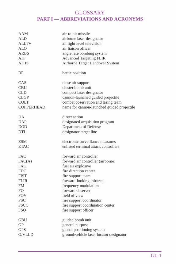
GLOSSARYPART I — ABBREVIATIONS AND ACRONYMS
GL-1
AAM air-to-air missileALD airborne laser designatorALLTV all light level televisionALO air liaison officerARBS angle rate bombing systemATF Advanced Targeting FLIRATHS Airborne Target Handover System
BP battle position
CAS close air supportCBU cluster bomb unitCLD compact laser designatorCLGP cannon-launched guided projectileCOLT combat observation and lasing teamCOPPERHEAD name for cannon-launched guided projectile
DA direct actionDAP designated acquisition programDOD Department of DefenseDTL designator target line
ESM electronic surveillance measuresETAC enlisted terminal attack controllers
FAC forward air controllerFAC(A) forward air controller (airborne)FAE fuel air explosiveFDC fire direction centerFIST fire support teamFLIR forward-looking infraredFM frequency modulationFO forward observerFOV field of viewFSC fire support coordinatorFSCC fire support coordination centerFSO fire support officer
GBU guided bomb unitGP general purposeGPS global positioning systemG/VLLD ground/vehicle laser locator designator
GL-2
Glossary
Joint Pub 3-09.1
HE high explosivesHEI high explosives incendiaryHUD heads-up display
IAW in accordance withIDM improved data modemIP initial pointIR infrared
J-3 Operations Directorate of a joint staff
km kilometer
LANTIRN low-altitude navigation and targeting infrared fornight
LDO laser designator operatorLEP laser eye protectionLGB laser-guided bombLGM laser-guided missileLGW laser-guided weaponLIF light interference filterLLLGB low-level laser-guided bombLLLTV low-light level televisionLMAV laser MaverickLOAL lock-on after launchLOAL-D lock-on after launch-directLOBL lock-on before launchLOS line of sightLRF/D laser range finder/detectorLST laser spot trackerLTD laser target designatorLTD/R laser target designator/ranger
MAGTF Marine air-ground task forceMEU(SOC) Marine expeditionary unit (special operations capable)MMS mast-mounted sightMSL mean sea levelMTO message to observerMULE modular universal laser equipment
NFLIR navigation forward-looking infraredNGF naval gun fireNOHD nominal ocular hazard distanceNTS night targeting systemNVG night vision goggleNVS night vision system
GL-3
Glossary
PLS precision locator systemPRF pulse repetition frequency
SEAD suppression of enemy air defensesSEAL sea-air-land teamSOF special operations forcesSOFLAM special operations laser markerSOTAC special operations terminal attack controllerSSB single side band
TACP tactical air control partyTADS target acquisition system and designation sightTFLIR targeting forward-looking infraredTOF time of flightTOW tube launched, optically tracked, wire guided
UHF ultra high frequencyUSAF United States Air ForceUSMC United States Marine CorpsUSN United States Navy
VHF very high frequencyVIXL video transmission downlink
WP white phosphorous
air liaison officer. An officer (aviator/pilot)attached to a ground unit who functions asthe primary advisor to the groundcommander on air operation matters. Alsocalled ALO. (This term and its definitionmodify the existing term and its definitionand are approved for inclusion in the nextedition of Joint Pub 1-02.)
at my command. In artillery and navalgunfire support, the command used whenit is desired to control the exact time ofdelivery of fire. (Joint Pub 1-02)
attack heading. 1. The interceptor headingduring the attack phase that will achievethe desired track-crossing angle. 2. Theassigned magnetic compass heading to beflown by aircraft during the delivery phaseof an air strike. (Joint Pub 1-02)
backscatter. Refers to a portion of the laserenergy that is scattered back in the directionof the seeker by an obscurant. (Uponapproval of this revision, this term and itsdefinition will be approved for inclusion inthe next edition of Joint Pub 1-02.)
buffer zone. A conical volume centered onthe laser’s line-of-sight with its apex at theaperture of the laser, within which the beamwill be contained with a high degree ofcertainty. It is determined by the bufferangle. (This term and its definition areapproved for inclusion in the next editionof Joint Pub 1-02.)
call for fire. A request for fire containingdata necessary for obtaining the requiredfire on a target. (Joint Pub 1-02)
close air support. Air action by fixed- androtary-wing aircraft against hostile targetswhich are in close proximity to friendlyforces and which require detailedintegration of each air mission with the fire
and movement of those forces. Also calledCAS. (Joint Pub 1-02)
enlisted terminal attack controller. Tacticalair party member who assists in missionplanning and provides final control of closeair support aircraft in support of groundforces. Also called ETAC. (This term andits definition are approved for inclusion inthe next edition of Joint Pub 1-02.)
fire support coordination center. A singlelocation in which are centralizedcommunications facilities and personnelincident to the coordination of all forms offire support. Also called FSCC. (This termand its definition modify the existing termand its definition and are approved forinclusion in the next edition of Joint Pub 1-02.)
fire support element. That portion of theforce tactical operations center at everyechelon above company or troop (to corps)that is responsible for targeting coordinationand for integrating fires delivered on surfacetargets by fire-support means under thecontrol, or in support, of the force. Alsocalled FSE. (This term and its definitionare approved for inclusion in the nextedition of Joint Pub 1-02.)
fire support officer. Senior field artilleryofficer assigned to Army maneuverbattalions and brigades. Advisescommander on fire-support matters. Alsocalled FSO. (This term and its definitionare approved for inclusion in the nextedition of Joint Pub 1-02.)
fire support team. An Army team providedby the field artillery component to eachmaneuver company and troop to plan andcoordinate all indirect fire means availableto the unit, including mortars, field artillery,close air support, and naval gunfire. Also
GL-4 Joint Pub 3-09.1
PART II — TERMS AND DEFINITIONS
called FIST. (This term and its definitionare approved for inclusion in the nextedition of Joint Pub 1-02.)
forward air controller. An officer (aviator/pilot) member of the tactical air controlparty who, from a forward ground orairborne position, controls aircraft in closeair support of ground troops. Also calledFAC. (This term and its definition modifythe existing term and its definition and areapproved for inclusion in the next editionof Joint Pub 1-02.)
forward observer. An observer operatingwith front line troops and trained to adjustground or naval gunfire and pass backbattlefield information. In the absence of aforward air controller the observer maycontrol close air support strikes. Also calledFO. (This term and its definition modifythe existing term and its definition and areapproved for inclusion in the next editionof Joint Pub 1-02.)
gated laser intensifier. This is part of theAC-130 low light level television (LLLTV)targeting system and is used as an alternatesource of IR illumination. It also has thecapability to illuminate and identify IR(“GLINT”) tape worn by friendly groundforces. The drawback of the GLINT is ithighlights the aircraft to enemy forces usingnight vision devices. Also called GLINT.(This term and its definition are approvedfor inclusion in the next edition of Joint Pub1-02.)
grid coordinates. Coordinates of a gridcoordinate system to which numbers andletters are assigned for use in designating apoint on a gridded map, photograph, orchart. (Joint Pub 1-02)
gun-target line. An imaginary straight linefrom gun to target. (Joint Pub 1-02)
head-up display. A display of flight,navigation, attack, or other informationsuperimposed upon the pilot’s forward fieldof view. Also called HUD. (This term andits definition modify the existing term andits definition and are approved for inclusionin the next edition of Joint Pub 1-02.)
infrared pointer. A low power laser deviceoperating in the near infrared light spectrumthat is visible with light amplifying nightvision devices. Also called IR pointer.(Joint Pub 1-02)
initial point. 1. The first point at which amoving target is located on a plotting board.2. A well-defined point, easilydistinguishable visually and/orelectronically, used as a starting point forthe bomb run to the target. 3. airborne - Apoint close to the landing area where serials(troop carrier air formations) make finalalterations in course to pass over individualdrop or landing zones. 4. helicopter - Anair control point in the vicinity of thelanding zone from which individual flightsof helicopters are directed to theirprescribed landing sites. 5. Any designatedplace at which a column or element thereofis formed by the successive arrival of itsvarious subdivisions, and comes under thecontrol of the commander ordering themove. Also called IP. (This term and itsdefinition modify the existing term and itsdefinition and are approved for inclusionin the next edition of Joint Pub 1-02.)
laser. Any device that can produce or amplifyoptical radiation primarily by the processof controlled stimulated emission. A lasermay emit electromagnetic radiation fromthe ultraviolet portion of the spectrumthrough the infrared portion. Also, anacronym for “light amplification bystimulated emission of radiation”. (Thisterm and its definition are approved for
GL-5
Glossary
GL-6
Glossary
Joint Pub 3-09.1
inclusion in the next edition of Joint Pub 1-02.)
laser footprint. The projection of the laserbeam and buffer zone on the ground ortarget area. The laser footprint may be partof the laser surface danger zone if thatfootprint lies within the nominal visualhazard distance of the laser. (This term andits definition are approved for inclusion inthe next edition of Joint Pub 1-02.)
laser-guided weapon. A weapon which usesa seeker to detect laser energy reflected froma laser marked/designated target andthrough signal processing providesguidance commands to a control systemwhich guides the weapon to the point fromwhich the laser energy is being reflected.Also called LGW. (This term and itsdefinition modify the existing term and itsdefinition and are approved for inclusionin the next edition of Joint Pub 1-02.)
laser rangefinder. A device which uses laserenergy for determining the distance fromthe device to a place or object. (Joint Pub1-02)
laser seeker. A device based on a directionsensitive receiver which detects the energyreflected from a laser designated target anddefines the direction of the target relativeto the receiver. (Joint Pub 1-02)
laser spot. The area on a surface illuminatedby a laser. (This term and its definition areapproved for inclusion in the next editionof Joint Pub 1-02.)
laser spot tracker. A device which locks onto the reflected energy from a laser-marked/designated target and defines the directionof the target relative to itself. Also calledLST. (This term and its definition modifythe existing term and its definition and areapproved for inclusion in the next editionof Joint Pub 1-02.)
laser target designator. A device that emitsa beam of laser energy which is used tomark a specific place or object. Also calledLTD. (This term and its definition modifythe existing term and its definition and areapproved for inclusion in the next editionof Joint Pub 1-02.)
laser-target/gun-target angle. The anglebetween the laser-to-target line and the laserguided weapon/gun-target line at the pointwhere they cross the target. (This term andits definition are approved for inclusion inthe next edition of Joint Pub 1-02.)
laser-target line. An imaginary straight linefrom the laser designator to the target withrespect to magnetic north. (This term andits definition are approved for inclusion inthe next edition of Joint Pub 1-02.)
loft bombing. A method of bombing in whichthe delivery plane approaches the target ata very low altitude, makes a definite pullupat a given point, releases the bomb at apredetermined point during the pullup, andtosses the bomb onto the target. (Joint Pub1-02)
milliradian. One thousandth of an anglewhose apex is at the center of a circle andthat subtends an arc of the circle equal inlength to the radius: equal to .0572958degrees. (This term and its definition areapplicable only in the context of thispublication and cannot be referencedoutside this publication.)
offset lasing. The technique of aiming a laserdesignator at a point other than the targetand, after laser acquisition, moving the laserto designate the target for terminal attackguidance. (This term and its definition areapproved for inclusion in the next editionof Joint Pub 1-02.)
point target. 1. A target of such smalldimension that it requires the accurate
GL-7
Glossary
placement of ordnance in order to neutralizeor destroy it. 2. nuclear - A target in whichthe ratio of radius of damage to target radiusis equal to or greater than 5. (Joint Pub1-02)
precision-guided munitions. A weapon thatuses a seeker to detect electromagneticenergy reflected from a target or referencepoint, and through processing, providesguidance commands to a control system thatguides the weapon to the target. Also calledPGM. (This term and its definition areapproved for inclusion in the next editionof Joint Pub 1-02.)
pulse code. A system of using selected pulse-repetition frequencies to allow a specificlaser seeker to acquire a target illuminatedby a specific laser designator. (This termand its definition are approved for inclusionin the next edition of Joint Pub 1-02.)
pulse repetition frequency. In lasers, thenumber of pulses that occur each second.(PRF should not be confused withtransmission frequency, which isdetermined by the rate at which cycles arerepeated within the transmitted pulse). Alsocalled PRF. (This term and its definitionmodify the existing term and its definitionand are approved for inclusion in the nextedition of Joint Pub 1-02.)
radar beacon. A receiver-transmittercombination which sends out a coded signalwhen triggered by the proper type of pulse,enabling determination of range andbearing information by the interrogatingstation or aircraft. (Joint Pub 1-02)
special operations terminal attackcontroller. USAF combat controlpersonnel certified to perform the terminalattack control function in support of SpecialOperations Forces missions. Specialoperations terminal attack controlleroperations emphasize the employment of
night infrared, laser, and beacon tactics andequipment. Also called SOTAC. (Thisterm and its definition are approved forinclusion in the next edition of Joint Pub 1-02.)
special tactics team. USAF SpecialOperations Forces with combat controllersassigned. The combat controllers arecertified air traffic controllers withadditional qualifications as SpecialOperations Terminal Attack Controllers forfire support operations. Also called STT.(This term and its definition modify theexisting term and its definition and areapproved for inclusion in the next editionof Joint Pub 1-02.)
spillover. The part of the laser spot that is noton the target because of beam divergenceor standoff range, improper boresighting oflaser designator, or poor operatorilluminating procedures. (This term and itsdefinition are approved for inclusion in thenext edition of Joint Pub 1-02.)
splash. 1. In artillery and naval gunfiresupport, word transmitted to an observeror spotter five seconds before the estimatedtime of the impact of a salvo or round. 2.In air interception, target destructionverified by visual or radar means. (JointPub 1-02)
spotter. An observer stationed for the purposeof observing and reporting results of navalgunfire to the firing agency and who alsomay be employed in designating targets.(Joint Pub 1-02)
tactical air control party. A subordinateoperational component of a tactical aircontrol system designed to provide airliaison to land forces and for the control ofaircraft. Also called TACP. (This term andits definition modify the existing term andits definition and are approved for inclusionin the next edition of Joint Pub 1-02.)

GL-8
Glossary
Joint Pub 3-09.1
target acquisition. The detection,identification, and location of a target insufficient detail to permit the effectiveemployment of weapons. (Joint Pub 1-02)
toss bombing. A method of bombing wherean aircraft flies on a line towards the target,
pulls up in a vertical plane, releasing thebomb at an angle that will compensate forthe effect of gravity drop on the bomb.Similar to loft bombing; unrestricted as toaltitude. (Joint Pub 1-02)

Assess-ments/
Revision
CJCSApproval
TwoDrafts
ProgramDirective
ProjectProposal
J-7 formally staffs withServices and CINCS
Includes scope ofproject, references,milestones, and who willdevelop drafts
J-7 releases ProgramDirective to Lead Agent.Lead Agent can beService, CINC, or JointStaff (JS) Directorate
STEP #2Program Directive
!
!
!
The CINCS receive the puband begin to assess it duringuse
18 to 24 months followingpublication, the Director J-7,will solicit a written report fromthe combatant commands andServices on the utility andquality of each pub and theneed for any urgent changes orearlier-than-scheduledrevisions
No later than 5 years afterdevelopment, each pub isrevised
STEP #5Assessments/Revision
!
!
!
ENHANCEDJOINT
WARFIGHTINGCAPABILITY
Submitted by Services, CINCS, or Joint Staffto fill extant operational void
J-7 validates requirement with Services andCINCs
J-7 initiates Program Directive
!
!
!
STEP #1Project Proposal
All joint doctrine and tactics, techniques, and procedures are organized into a comprehensive hierarchy asshown in the chart above. is in the series of joint doctrine publications. Thediagram below illustrates an overview of the development process:
Joint Pub 3-09.1 Operations
JOINT DOCTRINE PUBLICATIONS HIERARCHYJOINT DOCTRINE PUBLICATIONS HIERARCHY
JOINT PUB 1-0 JOINT PUB 2-0 JOINT PUB 3-0
PERSONNEL
JOINT PUB 4-0 JOINT PUB 5-0 JOINT PUB 6-0
LOGISTICSINTELLIGENCE OPERATIONS C4 SYSTEMSPLANS
JOINTDOCTRINE
PUBLICATION
Lead Agent forwards proposed pub to JointStaff
Joint Staff takes responsibility for pub, makesrequired changes and prepares pub forcoordination with Services and CINCS
Joint Staff conducts formalstaffing for approval as a Joint Publication
STEP #4CJCS Approval
!
!
!
Lead Agent selects Primary ReviewAuthority (PRA) to develop the pub
PRA develops two draft pubs
PRA staffs each draft with CINCS,Services, and Joint Staff
!
!
!
STEP #3Two Drafts
JOINT PUB 1
JOINTWARFARE
JOINT PUB 0-2
UNAAF