Embed Size (px)
Citation preview
JR CNC Router Table – (JR)^2, INC – Group #2
10/28/2014
JR CNC Router Table –
(JR)^2, INC – Group #2 Innovative Computer Numeric
Control Machine operated by a
mechanical arm
1 | P a g e
JR CNC Router Table – (JR)^2, INC – Group #2
Contents Chapter 1: Introduction ......................................................................................................................................................... 1
1.0 Design Goals .............................................................................................................................................................. 1
1.1 Problem Statement ...................................................................................................................................................... 1
1.2 Bench Marking ........................................................................................................................................................... 1
1.3 Identifying Customer Requirements and Needs ......................................................................................................... 1
a) In-Use Purposes and Market .............................................................................................................................. 1
b) Functional Requirements.................................................................................................................................... 1
c) Other Requirements............................................................................................................................................ 1
d) Corporate constraints.......................................................................................................................................... 1
e) Social, Political, and Legal Requirements ......................................................................................................... 1
f) Evaluating Customer Requirements and Needs ..................................................................................................... 1
1.4 Bench Marking ........................................................................................................................................................... 1
1.5 Energy Chart ............................................................................................................................................................... 1
1.5 Customer Need Matrix ............................................................................................................................................... 1
1.6 Customer Need Importance (Ranking) ....................................................................................................................... 1
Chapter 2: Proposal .............................................................................................................................................................. 1
2.0 Sketch ......................................................................................................................................................................... 1
2.1 Description of the operation ....................................................................................................................................... 1
2.2 List of materials and cost ............................................................................................................................................ 1
2.3 Review of the marketing and technical assessment ................................................................................................... 1
2.4 Necessary key tasks to develop design ....................................................................................................................... 1
2.5 Timeline ...................................................................................................................................................................... 1
2.6 Team Structure and Resource Management ............................................................................................................... 1
2.7 List of Specifications .................................................................................................................................................. 1
2.8 QFD (Quality Function Deployment) ........................................................................................................................ 1
2.9 Comments on the specifications ................................................................................................................................. 1
2.10 Data sources .............................................................................................................................................................. 1
Chapter 3: Detailed Product Design ..................................................................................................................................... 1
3.1 Preliminary Sketch of Important Parts/Assemblies .................................................................................................... 1
a) Possible layouts of the product........................................................................................................................... 1
3.2 Detailed Product Drawing .......................................................................................................................................... 1
3.3 Motion Analysis ......................................................................................................................................................... 1
(JR)2 CNC Router Table
Innovative Computer Numeric Control Machine operated by a mechanical arm

2 | P a g e
JR CNC Router Table – (JR)^2, INC – Group #2
3.4 Assembly View .......................................................................................................................................................... 1
a) Engineering Drawing of the Exploded Assembly View .................................................................................... 1
b) Bill of Material ................................................................................................................................................... 1
Chapter 4: Manufacturing Plan ............................................................................................................................................ 1
4.1 Manufacturing Processes of Designed Parts .............................................................................................................. 1
4.2 Schedule ..................................................................................................................................................................... 1
3 | P a g e
JR CNC Router Table – (JR)^2, INC – Group #2
Tables/Figures
Figure 1 ................................................................................................................................................................................. 1
Figure 2 ................................................................................................................................................................................. 1
Figure 3 ................................................................................................................................................................................. 1
Figure 4 ................................................................................................................................................................................. 1
Figure 5 ................................................................................................................................................................................. 1
Figure 6 ................................................................................................................................................................................. 1
Figure 7 ................................................................................................................................................................................. 1
Matrix 1 ................................................................................................................................................................................ 1
Matrix 2 ................................................................................................................................................................................ 1
Matrix 3 ................................................................................................................................................................................ 1
Preliminary Sketch 1 ............................................................................................................................................................ 1
Preliminary Sketch 2 ............................................................................................................................................................ 1
Preliminary Sketch 3 ............................................................................................................................................................ 1
Part Drawing 1 ...................................................................................................................................................................... 1
Part Drawing 2 ...................................................................................................................................................................... 1
Part Drawing 3 ...................................................................................................................................................................... 1
Part Drawing 4 ...................................................................................................................................................................... 1
Part Drawing 5 ...................................................................................................................................................................... 1
Part Drawing 6 ...................................................................................................................................................................... 1
Part Drawing 7 ...................................................................................................................................................................... 1
Part Drawing 8 ...................................................................................................................................................................... 1
Part Drawing 9 ...................................................................................................................................................................... 1
Assembly table
Innovative Computer Numeric Control Machine operated by a mechanical arm
(JR)2 CNC Router Table
4 | P a g e
JR CNC Router Table – (JR)^2, INC – Group #2
Chapter 1: Introduction
1.0 Design Goals
The goal of this team’s efforts is to develop a product that will establish (JR)2 Inc. which hopes to
revolutionize the market of such. Specifically, we were commissioned to design and manufacture
a CNC Router Table that is both innovative and functional. The team will create numerous
analyses, sketches, tests, surveys, customer need matrices and more so that one can be assured
that to go on the right path. It is important to mention that this project rose after catching
problems in the design and functionality of current CNC Tables existent on the market. This will
be clarified with details and numbers, and will be also further explained. As a result, (JR)2 Inc.
plans to accomplish the most innovative CNC Router Table. What follows is a description of the
product itself and information that helped the team to choose this specific project.
1.1 Problem Statement
After spending a long period of time researching and comparing the team’s idea to the ones that
are on the market, we immediately had the need to come up with solutions to certain problems
encountered. One of the most significant and most drastic problem is the fact that an operator is
restricted to the size (considering the width) of the material to be cut on the table. This is due to
the design of such tables; which is built with symmetry. As a result, operators are restricted and
obligated to use only the space that is provided by the table. The highly expensive price of such
machines was another problem that was spotted. This one in specific is very significant due to the
fact that it is not easily accessible to the targets; which are wood, aluminum and plastic
enthusiasts, wood-workers, and so on.
1.2 Bench Marking
By measuring our product’s ideas and comparing them to the competitors, we identified major
differences that will be on our benefit. This is because of the act of addressing the problems
found in such products. As a result, the team is very motivated to create a preliminary and
innovative design and hopes to create a product that is both productive and aesthetically pleasant.
1.3 Identifying Customer Requirements and Needs
It is to be understood that customers are the lifeblood of every company. They are the main
reason why products are developed in such form. The way the industry is set up, companies
attempt to use the customer’s need as much as possible; and as a result, they expect a profitable
return. Before this, they’ll need to identify and evaluate the customer requirements and needs.
Hence, it was a necessity for the team to follow this procedure in order to mature our idea.
Numerous customer requirements and needs can be found for the market that is being targeted.
To start, customers need to have the accessibility to purchase a quality and productive CNC
Router Table. They are also in the need of the incorporation of new technology. Least but not
last, customers need a more spacious table which can be used to cut larger piece of material
without being restricted to the width of such.
5 | P a g e
JR CNC Router Table – (JR)^2, INC – Group #2
1.3 (continuation) a) In-Use Purposes and Market
The name of the product to be designed is “(JR)2 CNC Router Table”. The function to be performed
is to cut any desired type of shape or letter by the use the famous Computer Numeric Control
system. Although that is its main purpose, such machine will carry a tremendous amount of special
features that will separate it from the existing ones. Such features are as follows:
a) One retractable mechanical arm
b) Perforated table top to debris to fall into the integrated dust collector
c) Inexpensive
d) Lightweight (usage of plastic and aluminum)
e) Integrated vacuum and blower line at the tool bit
f) Magnetized holder to store bits
g) Multi-size jig for operation of various tools and bit sizes
a. I.e., Engraving, cutting, drawing, etc.
h) LED light at the tool bit for better visibility
i) Anti-Vibration rubber feed (isolators)
The intended market are wood, aluminum and plastic enthusiasts, wood-workers, technical drawers,
industrial designers and more. The (JR)2 CNC Router Table can be said to share only simple
similarities to other companies’ products. This is due to the impressive amount of special features
that are incorporated into the machine. On the other hand, these special features do not increment
the final retail price of the product by much. The estimated retail price for the (JR)2 CNC Router
Table is about $2,500 dollars. This is a very reasonable price because if one compares this given
price to the retail price of existent similar machines, one will see a huge difference which is why
customers cannot purchase such machines.
b) Functional Requirements
Usage of CAD Software to create the desired design and input it into the CNC Router
Availability to cut larger pieces
Fitment of a wide variety of cutters
Suction of debris (top and bottom)
c) Other Requirements
Teknic Servo Motors (for precise motion)
MC901 Nylon for table frame
6061 Aluminum alloy posts for corners with threaded bottoms and perforated sheet for
table
Module 0.5 / injection molded Acetal gears
Precision chrome steel shaft for guide rails
End-support pillow block bearings for each lead screw
Self-lubricating flanged bronze sleeve bushings for shafts
Composite material for the arm structure and counter-weights
NOTE: Other than designing and manufacturing this product, (JR)2 Inc will also create a customer
6 | P a g e
JR CNC Router Table – (JR)^2, INC – Group #2
1.3 (continuation)
d) Corporate constraints
Due to the seriousness of the customer need to be able to purchase a CNC machine, the time
to design, manufacture and do the marketing is very limited. In addition, there are
manufacturing requirements that need to be followed in order to give a final product which
will exhibit and ensure top quality. For example, the team needs to manufacture an aluminum
table top which will be perforated around the whole area. Also, to manufacture and assembly
the frame of the machine table can require a lot of time. But, due to the team’s optimism and
determination, we are more than sure that we will complete this project within two months. It
is important to mention the financial aspect as well. We are constraint to an approximate of
$250 dollars which was donated to us in order to help the project get started. But, aside from
this money, the team will collect money from each other in order to accomplish our goals.
Also, since the team members work in the construction and gear production’ area, it will be
easy for us to bring any material at a very cheap price.
e) Social, Political, and Legal Requirements
It is to be understood that Social, Political, and Legal requirements are a very important
aspect when designing or manufacturing a product. It plays a very important role, which
should be taken care very seriously because the success of your company are dependent on a
large scale to these requirements. Similar to every product that is on the market, (JR)2 Inc.
will follow every single regulation and requirements. This will help us be more protected and
assure that we will not have any future issues pertaining to lawsuits and so on.
The team will make sure to complete all the legal requirements. We will post safety images
on the machine that will be highly visible. In addition, we will supply our customers with an
operation and safety manual in order to decrease the chance of injuries. Also, the (JR)2 CNC
Router Table will have a one year warranty and an unlimited time 24-hours customer service.
f) Evaluating Customer Requirements and Needs
After spending a long period of time evaluating customer requirements and needs, the (JR)2
Inc.’ team is very enthusiastic to start the project and work towards the completion of such. It
is very likely that one will see a very high profitable return due to this innovative idea and
also because problems that were spotted during the research time are being addressed in the
best possible form. Customer satisfaction is our priority and we won’t rest until they
appreciate our effort to make an easily accessible CNC Machine.
7 | P a g e
JR CNC Router Table – (JR)^2, INC – Group #2
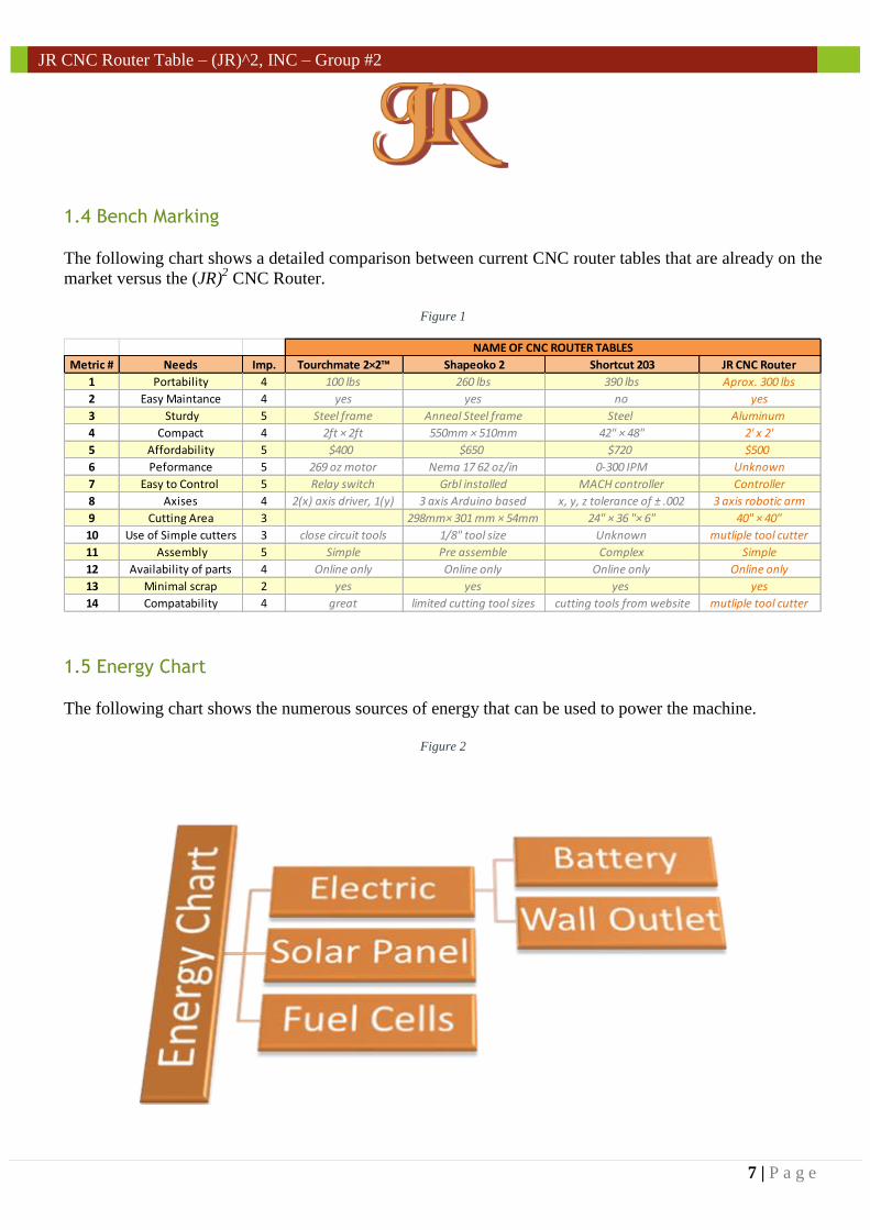
1.4 Bench Marking
The following chart shows a detailed comparison between current CNC router tables that are already on the
market versus the (JR)2 CNC Router.
Figure 1
1.5 Energy Chart
The following chart shows the numerous sources of energy that can be used to power the machine.
Figure 2
Metric # Needs Imp. Tourchmate 2×2™ Shapeoko 2 Shortcut 203 JR CNC Router
1 Portability 4 100 lbs 260 lbs 390 lbs Aprox. 300 lbs
2 Easy Maintance 4 yes yes no yes
3 Sturdy 5 Steel frame Anneal Steel frame Steel Aluminum
4 Compact 4 2ft × 2ft 550mm × 510mm 42" × 48" 2' x 2'
5 Affordability 5 $400 $650 $720 $500
6 Peformance 5 269 oz motor Nema 17 62 oz/in 0-300 IPM Unknown
7 Easy to Control 5 Relay switch Grbl installed MACH controller Controller
8 Axises 4 2(x) axis driver, 1(y) 3 axis Arduino based x, y, z tolerance of ± .002 3 axis robotic arm
9 Cutting Area 3 298mm× 301 mm × 54mm 24" × 36 "× 6" 40" × 40"
10 Use of Simple cutters 3 close circuit tools 1/8" tool size Unknown mutliple tool cutter
11 Assembly 5 Simple Pre assemble Complex Simple
12 Availability of parts 4 Online only Online only Online only Online only
13 Minimal scrap 2 yes yes yes yes
14 Compatability 4 great limited cutting tool sizes cutting tools from website mutliple tool cutter
NAME OF CNC ROUTER TABLES
8 | P a g e
JR CNC Router Table – (JR)^2, INC – Group #2
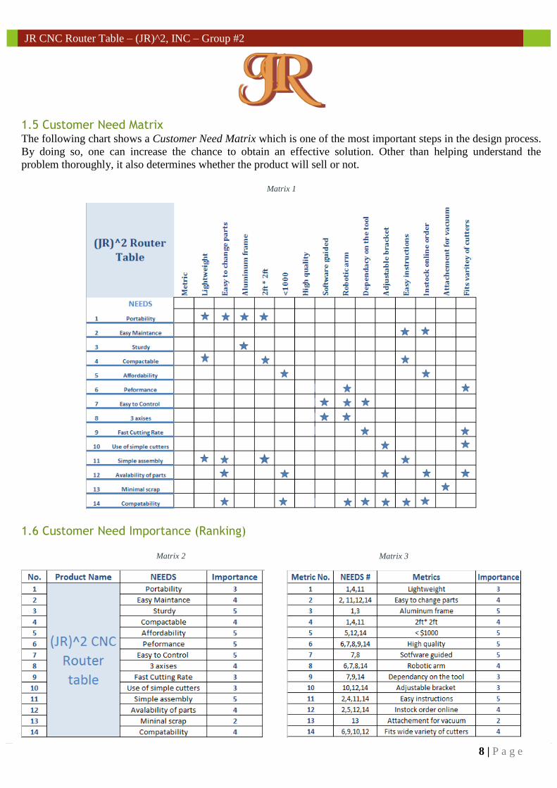
1.5 Customer Need Matrix The following chart shows a Customer Need Matrix which is one of the most important steps in the design process.
By doing so, one can increase the chance to obtain an effective solution. Other than helping understand the
problem thoroughly, it also determines whether the product will sell or not.
Matrix 1
1.6 Customer Need Importance (Ranking)
Matrix 2
Matrix 3
9 | P a g e
JR CNC Router Table – (JR)^2, INC – Group #2
10/28/2014
JR CNC Router Table –
(JR)^2, INC – Group #2 Innovative Computer Numeric
Control Machine operated by a
mechanical arm
Chapter 2
10 | P a g e
JR CNC Router Table – (JR)^2, INC – Group #2
2.1 Description of the operation
After spending a
2.2 List of Materials and Cost
2.6 Timeline
By measuring our product’s ideas and comparing them to the competitors, we identified
major differences that will be on our benefit. This is because of the act of addressing the
problems found in such products. As a result, the team is very motivated to create a
preliminary and innovative design and hopes to create a product that is both productive
and aesthetically pleasant.
2.7 Team structure and resource management plan
It is to be understood that customers are the lifeblood of every company. They are the
main reason why products are developed in such form. The way the industry is set up,
companies attempt to use the customer’s need as much as possible; and as a result, they
expect a profitable return. Before this, they’ll need to identify and evaluate the customer
requirements and needs. Hence, it was a necessity for the team to follow this procedure in
order to mature our idea.
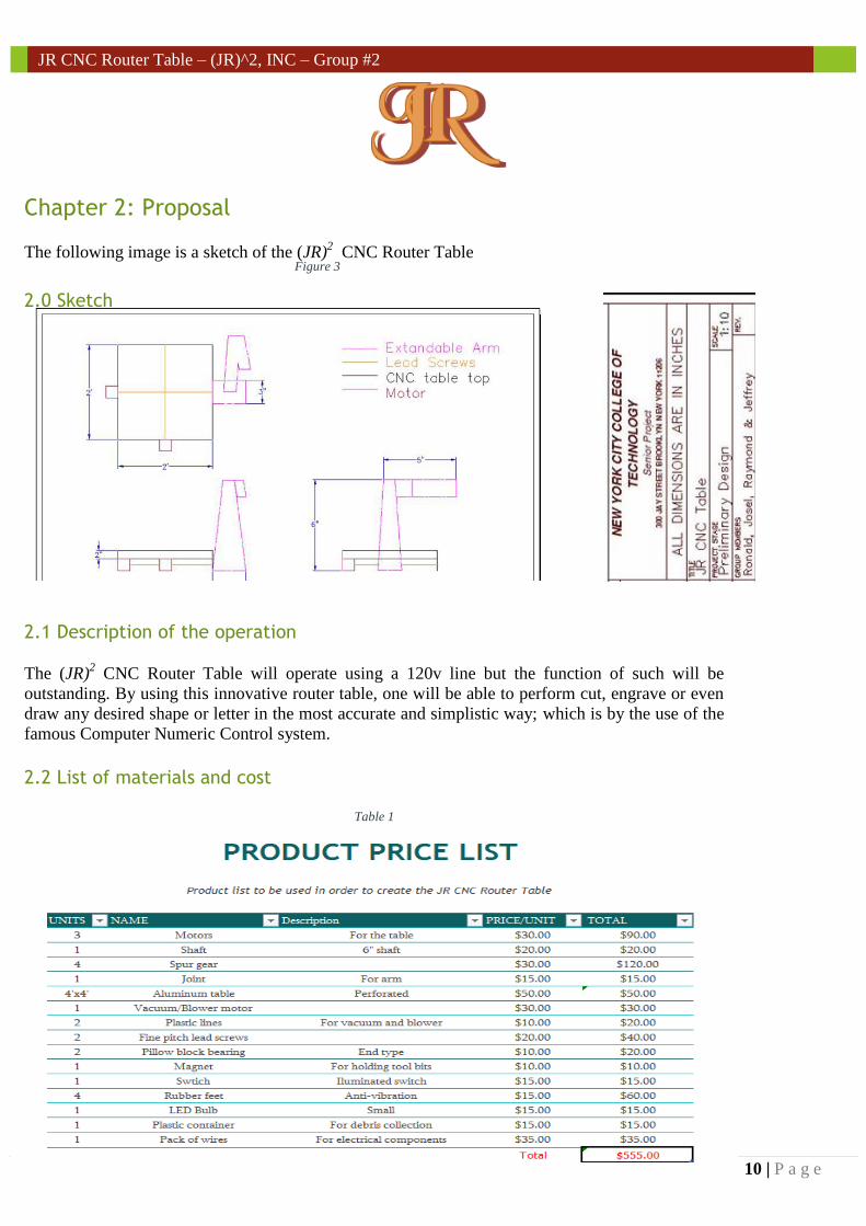
Chapter 2: Proposal
The following image is a sketch of the (JR)2 CNC Router Table
2.0 Sketch
2.1 Description of the operation
The (JR)2 CNC Router Table will operate using a 120v line but the function of such will be
outstanding. By using this innovative router table, one will be able to perform cut, engrave or even
draw any desired shape or letter in the most accurate and simplistic way; which is by the use of the
famous Computer Numeric Control system.
2.2 List of materials and cost
Table 1
Figure 3
11 | P a g e
JR CNC Router Table – (JR)^2, INC – Group #2
2.3 Review of the marketing and technical assessment
Before the team came into an agreement to proceed with this prestigious project, a lot of
research and analysis was done. A summary of such analyses are as follows:
Market Analysis: Due to the fact that these machines are a one-time-buy only, the
complexity of creating one and how recent they are, they are priced very high. As a
result, companies that design and manufacture this machines, tend not to sell a lot
of them. On the other hand, there are a lot of people who would like to buy one but
cannot afford it. Therefore, the team decided to make an inexpensive one but yet
one that makes a difference.
Specifications: CNC Router tables are able to handle various routers with different
HP (horse power); but this depends on the structure of such and in the motors that
are used. But, the most common router HP that a CNC Machine can take is
approximately 3.5HP which has the ability to do a very outstanding performance.
Functional Analysis: The functionality of the existent CNC Router table meet the
requirements but lack of a very important factor which is space. Operators with
such Router tables are limited to the size of the materials to cut due to how the
machine is built.
2.4 Necessary key tasks to develop design
The process of developing the design of the (JR)2 CNC Router Table was a bit challenging
and time consuming. Similar to any other concept or existing product, our design was
inspired by comparing it to other designs and trying to give it a different approach. It is to
be acknowledged that our experiences, passion, creativity and intelligence influenced a lot
as well. We created many sketches with the intention to evaluate them to pick one or mix
the possible winners. Throughout this process, the team encountered some barriers that
needed to be faced in the most positive way and attempt to overcome them. For example,
the fact that the structure of every CNC Router Table in the market was built in similar
ways affected us by doubting if our concept will work or not. Also, the team
acknowledged that a very challenging part to be faced was the programming part; since
none of us have experience in that field. Least but not last, a necessary key task that helped
to develop the design was by thinking about customer needs. This helped in a tremendous
way and because of this, we incorporated special features on the (JR)2 CNC Router Table
in order to address the customer needs.
12 | P a g e
JR CNC Router Table – (JR)^2, INC – Group #2
2.5 Timeline
Week 1-3: Sketch and design of the CNC router table
Create a list of parts needed with its cost. Then breakdown each part of the CNC router
into components of design (arm, base, table, etc.) for calculations and refinement.
During this time, the group will come up with an ideal of the model to make and create
a close sketch to what is expected. Furthermore, the team will make changes to the
ideal to better suit customer needs as well as making it practical and doable.
Week 4-5: Calculations and refining the design of the CNC router
During these two weeks, the group will take each component of the CNC router and
run simulation testes on the components to make sure everything is safe and functional
to be incorporated into the design of our CNC router.
Once each part passes the tests, the group will then continue with the refinement of the
design to produce our final sketch and design of the project.
Week 6-7: Construct the Base for the CNC router
It will take the group approximately two weeks to put the base of the CNC table
together. Also, it will give us a chance to make any necessary adjustments to the
design or base if needed
Week 8-11: Assembly of the Mechanical Arm and testing motors
Three weeks will be spent on assembling the mechanical arm and making sure each
motor works for the specific direction it should travel in. This is a vital part of our
CNC router, so testing and adjusting is critical during these weeks.
Week 12-14: Computer programming
Our group will have to use the remaining few weeks to write the programming codes
for the CNC router. It’s a very tedious task but crucial since the codes are the brains of
our CNC router; which is responsible for carrying out the commands that are inputted
into the computer.
Week 15: Final Presentation
If all goes well, the team should be able to present the finish product to the class. The
final design (CAD) and the physical assembly should be presented along with a final
report.
13 | P a g e
JR CNC Router Table – (JR)^2, INC – Group #2
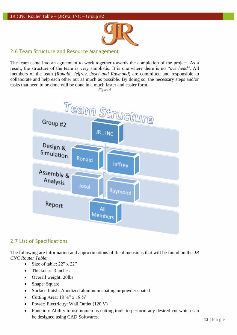
2.6 Team Structure and Resource Management
The team came into an agreement to work together towards the completion of the project. As a
result, the structure of the team is very simplistic. It is one where there is no “overhead”. All
members of the team (Ronald, Jeffrey, Josel and Raymond) are committed and responsible to
collaborate and help each other out as much as possible. By doing so, the necessary steps and/or
tasks that need to be done will be done in a much faster and easier form. Figure 4
2.7 List of Specifications
The following are information and approximations of the dimensions that will be found on the JR
CNC Router Table;
Size of table: 22” x 22”
Thickness: 3 inches.
Overall weight: 20lbs
Shape: Square
Surface finish: Anodized aluminum coating or powder coated
Cutting Area: 18 ½” x 18 ½”
Power: Electricity: Wall Outlet (120 V)
Function: Ability to use numerous cutting tools to perform any desired cut which can
be designed using CAD Softwares.
14 | P a g e
JR CNC Router Table – (JR)^2, INC – Group #2
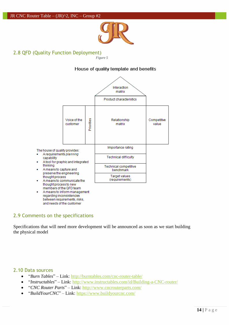
2.8 QFD (Quality Function Deployment) Figure 5
2.9 Comments on the specifications
Specifications that will need more development will be announced as soon as we start building
the physical model
2.10 Data sources “Burn Tables” – Link: http://burntables.com/cnc-router-table/
“Instructables” – Link: http://www.instructables.com/id/Building-a-CNC-router/
“CNC Router Parts” – Link: http://www.cncrouterparts.com/
“BuildYourCNC” – Link: https://www.buildyourcnc.com/
15 | P a g e
JR CNC Router Table – (JR)^2, INC – Group #2
10/28/2014
JR CNC Router Table –
(JR)^2, INC – Group #2 Innovative Computer Numeric
Control Machine operated by a
mechanical arm
Chapter 3
16 | P a g e
JR CNC Router Table – (JR)^2, INC – Group #2
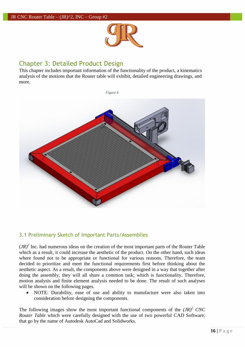
Chapter 3: Detailed Product Design This chapter includes important information of the functionality of the product, a kinematics
analysis of the motions that the Router table will exhibit, detailed engineering drawings, and
more.
Figure 6
3.1 Preliminary Sketch of Important Parts/Assemblies
(JR)2 Inc. had numerous ideas on the creation of the most important parts of the Router Table
which as a result, it could increase the aesthetic of the product. On the other hand, such ideas
where found not to be appropriate or functional for various reasons. Therefore, the team
decided to prioritize and meet the functional requirements first before thinking about the
aesthetic aspect. As a result, the components above were designed in a way that together after
doing the assembly, they will all share a common task; which is functionality. Therefore,
motion analysis and finite element analysis needed to be done. The result of such analyses
will be shown on the following pages.
NOTE: Durability, ease of use and ability to manufacture were also taken into
consideration before designing the components.
The following images show the most important functional components of the (JR)2 CNC
Router Table which were carefully designed with the use of two powerful CAD Software;
that go by the name of Autodesk AutoCad and Solidworks.
17 | P a g e
JR CNC Router Table – (JR)^2, INC – Group #2
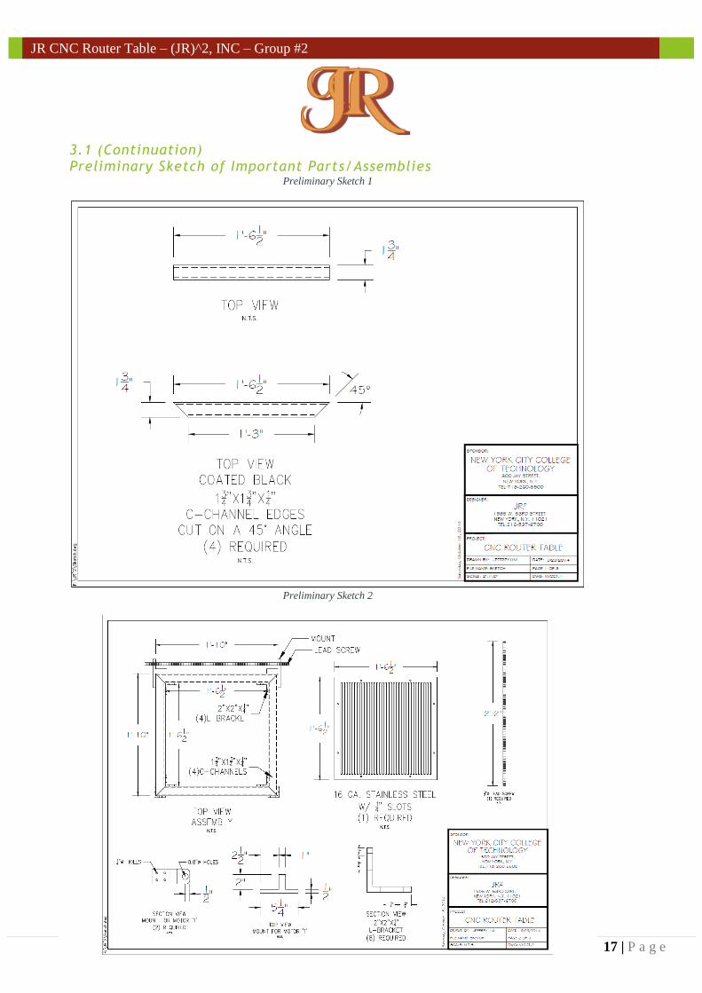
3.1 (Continuation) Preliminary Sketch of Important Parts/Assemblies
Preliminary Sketch 1
Preliminary Sketch 2
18 | P a g e
JR CNC Router Table – (JR)^2, INC – Group #2
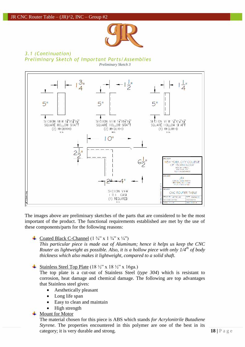
3.1 (Continuation) Preliminary Sketch of Important Parts/Assemblies
Preliminary Sketch 3
The images above are preliminary sketches of the parts that are considered to be the most
important of the product. The functional requirements established are met by the use of
these components/parts for the following reasons:
Coated Black C-Channel (1 ¾” x 1 ¾” x ¼”)
This particular piece is made out of Aluminum; hence it helps us keep the CNC
Router as lightweight as possible. Also, it is a hollow piece with only 1/4th
of body
thickness which also makes it lightweight, compared to a solid shaft.
Stainless Steel Top Plate (18 ½” x 18 ½” x 16ga.)
The top plate is a cut-out of Stainless Steel (type 304) which is resistant to
corrosion, heat damage and chemical damage. The following are top advantages
that Stainless steel gives:
Aesthetically pleasant
Long life span
Easy to clean and maintain
High strength
Mount for Motor
The material chosen for this piece is ABS which stands for Acrylonitrile Butadiene
Styrene. The properties encountered in this polymer are one of the best in its
category; it is very durable and strong.
19 | P a g e
JR CNC Router Table – (JR)^2, INC – Group #2
3.1 (Continuation) Preliminary Sketch of Important Parts/Assemblies
L-Bracket (2” x 2” ¼”)
The material chosen for the L-Bracket is Stainless Steel (type 304) which is
appropriate and helps the team met the functional requirements. The Stainless Steel
provides high strength which results in long-life span and it is also aesthetically
pleasant which in this case it is very important since these L-Brackets will visible.
Square Hollow Shafts
The Square Hollow Shafts are made out of aluminum. This helps the CNC Router
Table Robot Arm to be lightweight; which is a very important requirement to (JR)2
Inc.
T Reel Case
The T-Reel Case is a custom part that helps with the incorporation of the flex-rack
and the tension cable. The material chosen is PC_ABS Plastic which is strong
enough to sustain any forces.
a) Possible layouts of the product
The team had a general idea of the layouts of the (JR)2 CNC Router Table but as time went
by, numerous changes were made in order to meet the functional requirements that were
set. At first, the team considered a 2’ x 2’ table which was then shortened to 18 ½” x 18
½” due dimensioning constraints caused by the Robotic Arm Shafts which couldn’t be
extended to 24in. Secondly, (JR)2 Inc., had the idea to follow the trend and use the most
common design in order to minimize errors. But, after running analysis and research, the
team realized that changes in the design needed to be made. These changes resulted in
having a robotic arm on one side of the table instead of a two guided rail shafts which are
found in existent CNC Router Tables. This helps an operator to cut materials that are
larger and wider due to not having a size constraint anymore. Thirdly, the team planned to
create a product as lightweight as possible and use ABS Plastic to help obtain the desired
results. Unfortunately, this couldn’t become true due to the fact that ABS Plastic is not
strong enough to hold the material weight in the cutting area (top plate) and it is also not
durable. As a result, the team desired to work using Aluminum and stainless steel. Another
important change is one that wasn’t expected. The team decided to go beyond and build a
system that has the ability to create cuts in 3 Axis. At first, the CNC Router Table was
meant to only have two degrees of freedom. Another change was made during the analysis
of possible layouts. This change involves the change of functional parts such as the gear
and the motors. Furthermore, the team decided to use flex-rack instead of gears because it
was the best possible way to extend the Robotic Arm Shaft. This decision was made by the
use of our design matrix.
20 | P a g e
JR CNC Router Table – (JR)^2, INC – Group #2
``
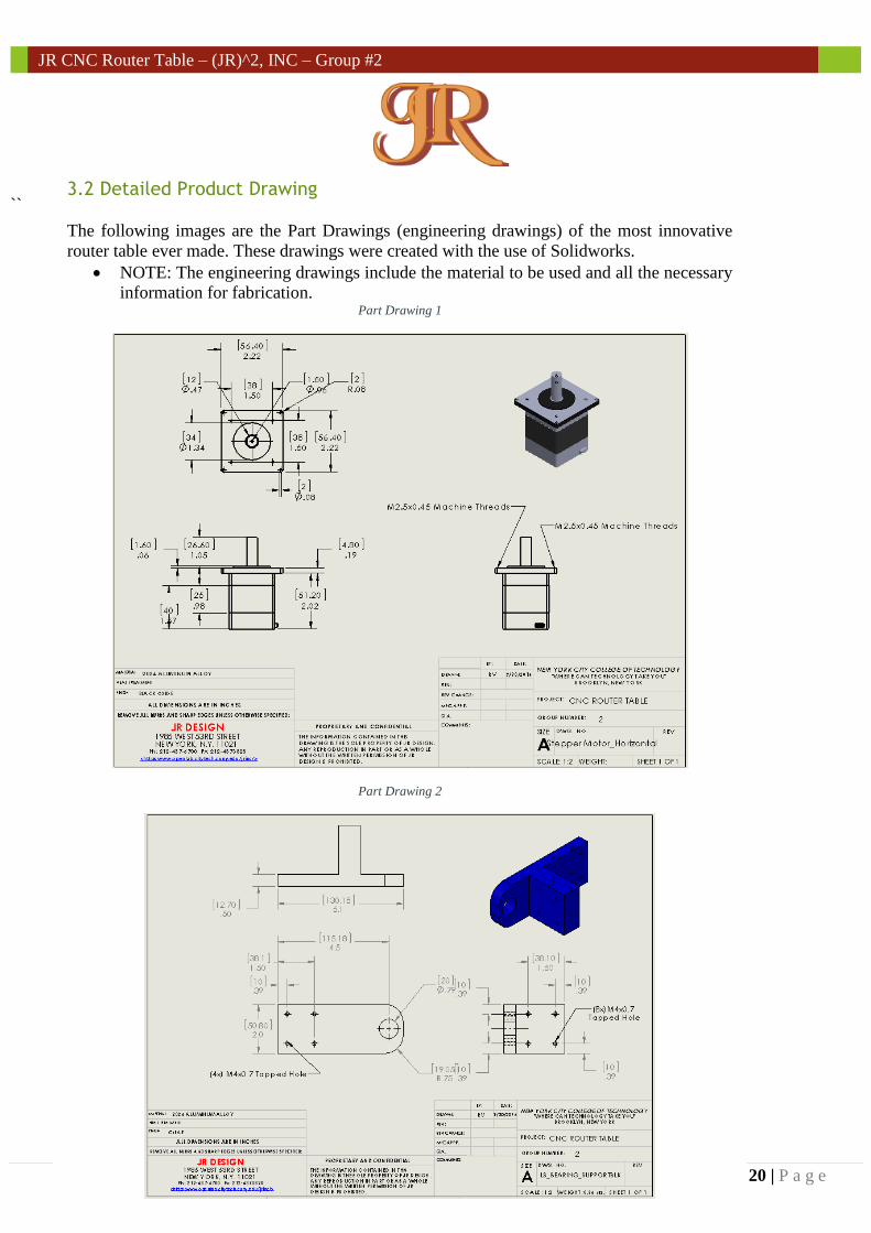
3.2 Detailed Product Drawing
The following images are the Part Drawings (engineering drawings) of the most innovative
router table ever made. These drawings were created with the use of Solidworks.
NOTE: The engineering drawings include the material to be used and all the necessary
information for fabrication. Part Drawing 1
Part Drawing 2
21 | P a g e
JR CNC Router Table – (JR)^2, INC – Group #2
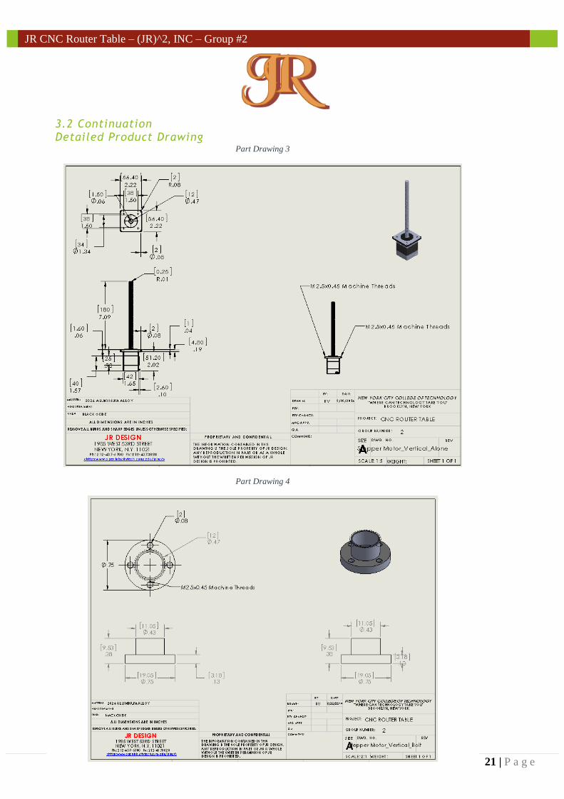
3.2 Continuation Detailed Product Drawing
Part Drawing 3
Part Drawing 4
22 | P a g e
JR CNC Router Table – (JR)^2, INC – Group #2
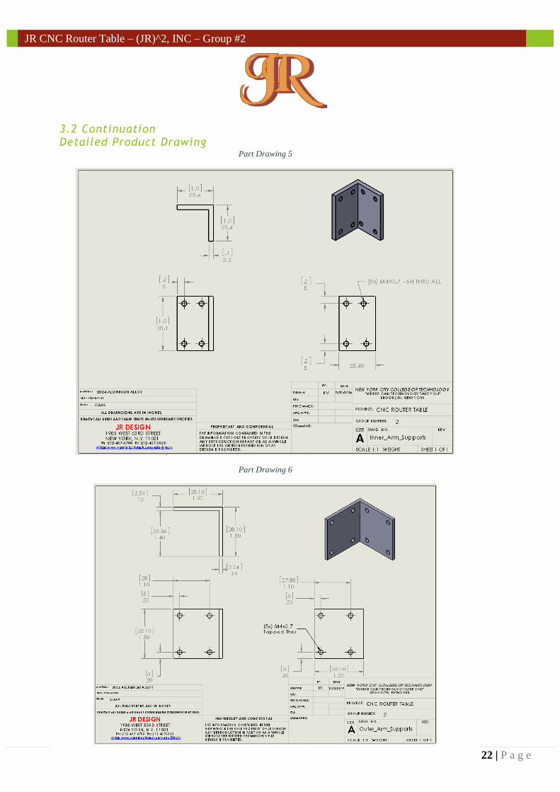
3.2 Continuation Detailed Product Drawing
Part Drawing 5
Part Drawing 6
23 | P a g e
JR CNC Router Table – (JR)^2, INC – Group #2
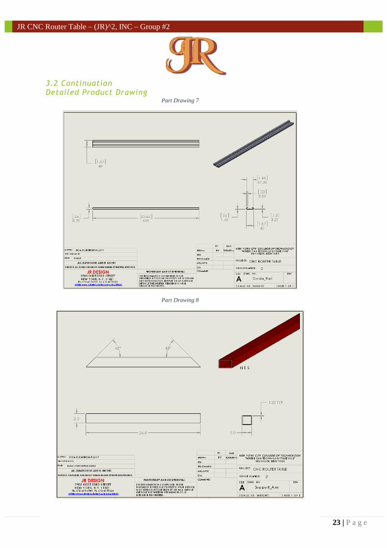
3.2 Continuation Detailed Product Drawing
Part Drawing 7
Part Drawing 8
24 | P a g e
JR CNC Router Table – (JR)^2, INC – Group #2
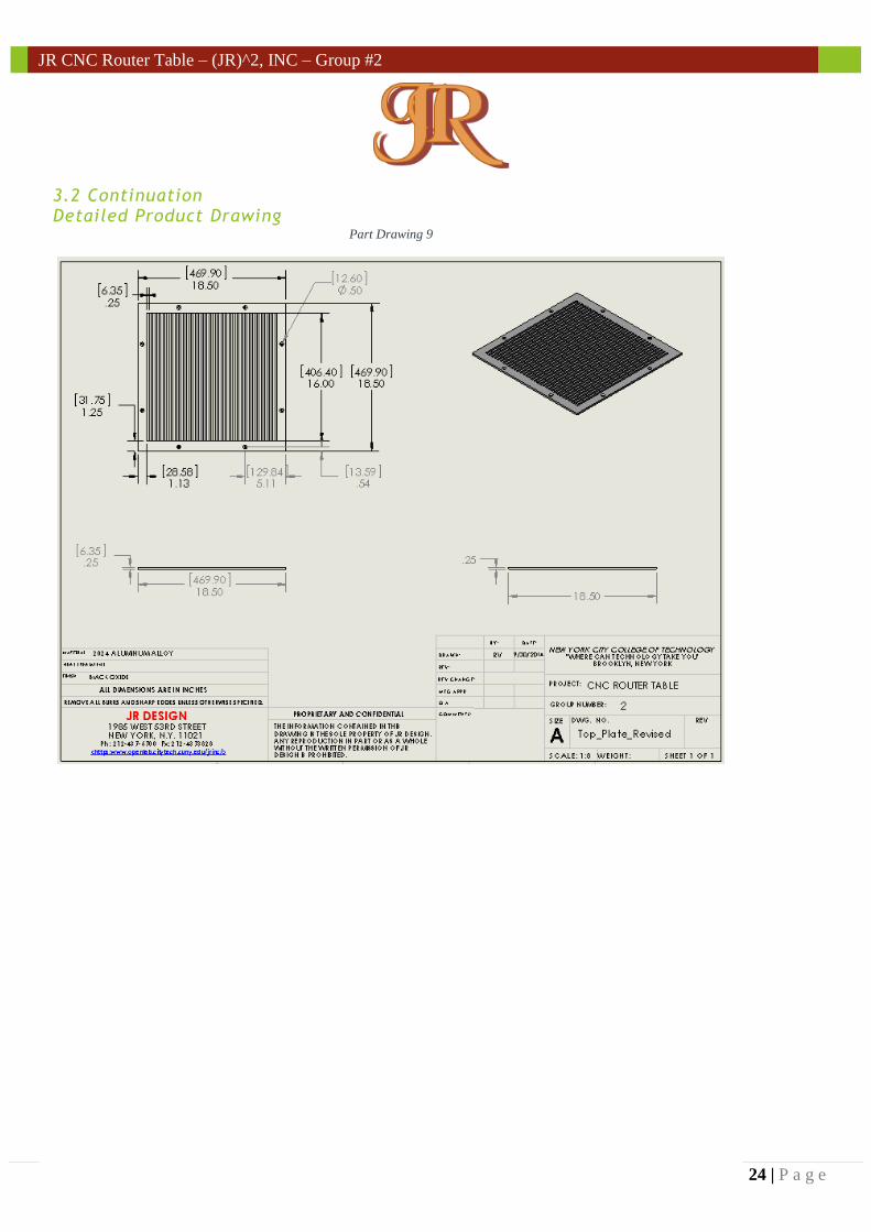
3.2 Continuation Detailed Product Drawing
Part Drawing 9
25 | P a g e
JR CNC Router Table – (JR)^2, INC – Group #2
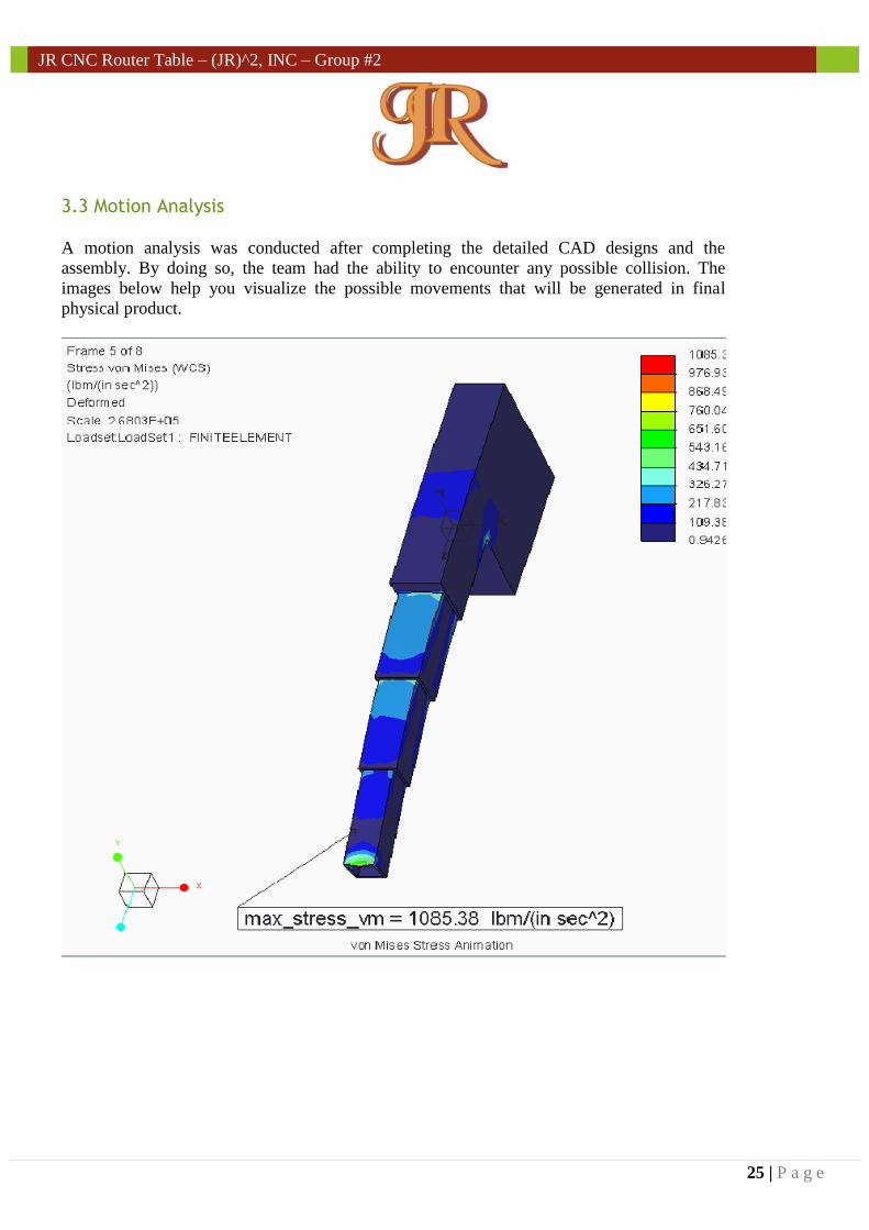
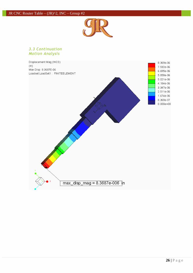
3.3 Motion Analysis
A motion analysis was conducted after completing the detailed CAD designs and the
assembly. By doing so, the team had the ability to encounter any possible collision. The
images below help you visualize the possible movements that will be generated in final
physical product.
26 | P a g e
JR CNC Router Table – (JR)^2, INC – Group #2
3.3 Continuation Motion Analysis
27 | P a g e
JR CNC Router Table – (JR)^2, INC – Group #2
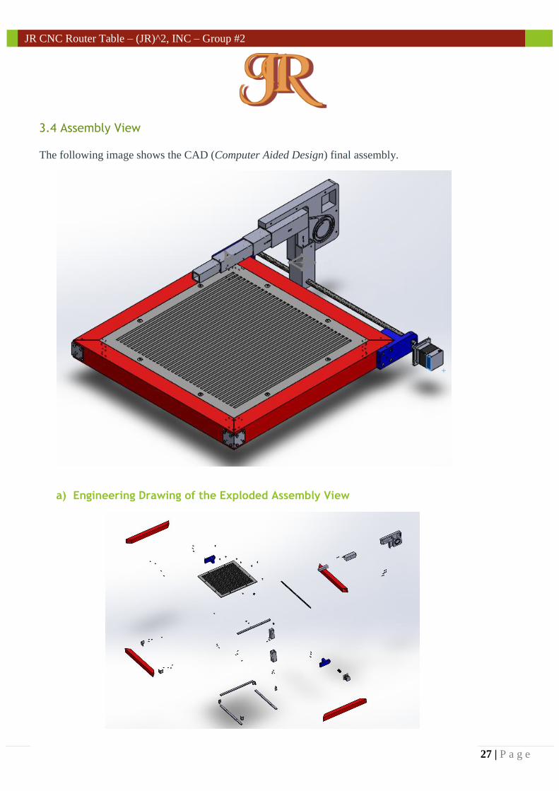
3.4 Assembly View
The following image shows the CAD (Computer Aided Design) final assembly.
a) Engineering Drawing of the Exploded Assembly View
28 | P a g e
JR CNC Router Table – (JR)^2, INC – Group #2
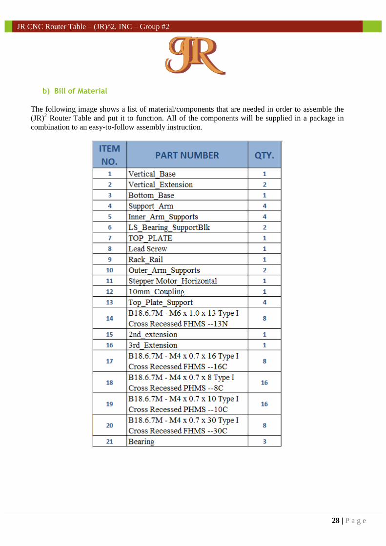
b) Bill of Material
The following image shows a list of material/components that are needed in order to assemble the
(JR)2 Router Table and put it to function. All of the components will be supplied in a package in
combination to an easy-to-follow assembly instruction.
29 | P a g e
JR CNC Router Table – (JR)^2, INC – Group #2
10/28/2014
JR CNC Router Table –
(JR)^2, INC – Group #2 Innovative Computer Numeric
Control Machine operated by a
mechanical arm
Chapter 4
30 | P a g e
JR CNC Router Table – (JR)^2, INC – Group #2
Chapter 4: Manufacturing Plan
4.1 Manufacturing Processes of Designed Parts
It is to be understood that the manufacturing process should be well planned before it starts. The
disposition of time as well as the availability of materials, components and tools/equipment
needs to be considered. Fortunately, by creating research beforehand and a detailed product
design; helps (JR)2 Inc. tremendously. This is because the team knows the availability of the
material and components that were considered since it was decided during the design process.
Least but not last, it is important to mention that the team plans to manufacture certain parts due
to the fact that they are special (non-standard) pieces.
It is possible that the team may encounter problems when the manufacturing process of the parts
starts. This is a very realistic and common situation which occurs in the manufacturing world.
On the other hand, it can be avoided at the design stage. In the case of (JR)2 Inc., the team spent
a long period of time thinking about possible errors that can be encountered and for those,
solutions were brought up. For example, if the selection of a specific material can cause
negative effects, the team should consider alternative options at the design stage. This will help
avoid futuristic problems.
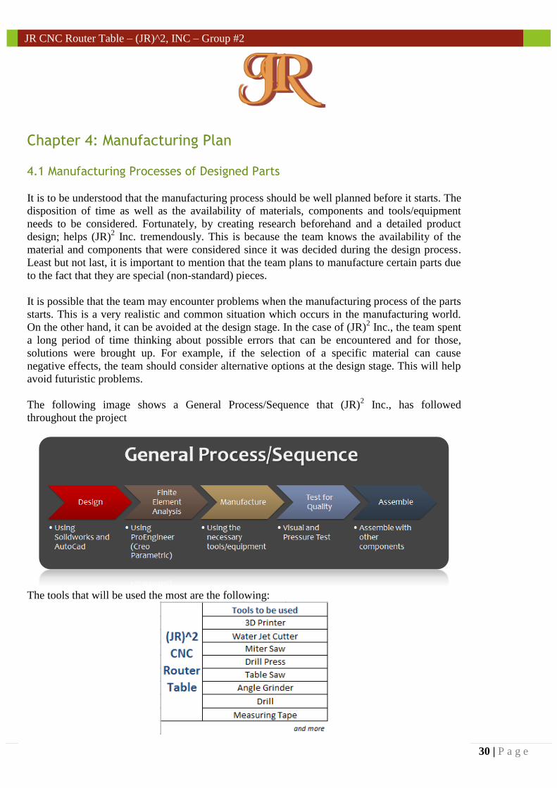
The following image shows a General Process/Sequence that (JR)2 Inc., has followed
throughout the project
The tools that will be used the most are the following:
Explain the general sequence of building these parts using available tools.
Explain manufacturing process (including equipment used and important parameters)
31 | P a g e
JR CNC Router Table – (JR)^2, INC – Group #2
4.1 Continuation Manufacturing Processes of Designed Parts
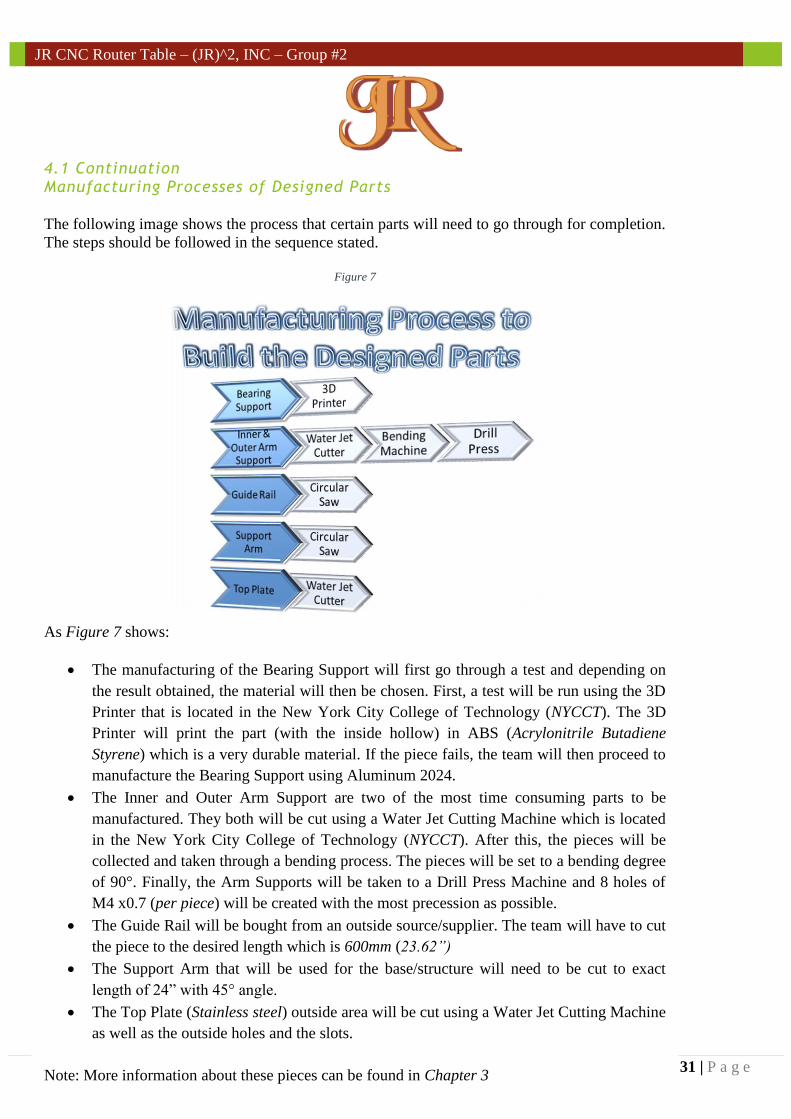
The following image shows the process that certain parts will need to go through for completion.
The steps should be followed in the sequence stated.
Figure 7
As Figure 7 shows:
The manufacturing of the Bearing Support will first go through a test and depending on
the result obtained, the material will then be chosen. First, a test will be run using the 3D
Printer that is located in the New York City College of Technology (NYCCT). The 3D
Printer will print the part (with the inside hollow) in ABS (Acrylonitrile Butadiene
Styrene) which is a very durable material. If the piece fails, the team will then proceed to
manufacture the Bearing Support using Aluminum 2024.
The Inner and Outer Arm Support are two of the most time consuming parts to be
manufactured. They both will be cut using a Water Jet Cutting Machine which is located
in the New York City College of Technology (NYCCT). After this, the pieces will be
collected and taken through a bending process. The pieces will be set to a bending degree
of 90°. Finally, the Arm Supports will be taken to a Drill Press Machine and 8 holes of
M4 x0.7 (per piece) will be created with the most precession as possible.
The Guide Rail will be bought from an outside source/supplier. The team will have to cut
the piece to the desired length which is 600mm (23.62”)
The Support Arm that will be used for the base/structure will need to be cut to exact
length of 24” with 45° angle.
The Top Plate (Stainless steel) outside area will be cut using a Water Jet Cutting Machine
as well as the outside holes and the slots.
Note: More information about these pieces can be found in Chapter 3

32 | P a g e
JR CNC Router Table – (JR)^2, INC – Group #2
4.2 Schedule
It is to be acknowledged that every project needs a detailed schedule that needs to be done
and followed very carefully in order to accomplish the main goal; which is to complete the
project assuring to meet the deliverables and on time. Hence, the team created a detailed
schedule which shows how the product will be built before the deadline set.