Embed Size (px)
Citation preview
EN Instruction Manual
B 46243-10-1503 www.jung-pumpen.de
JUNG PUMPEN WCFIX PLUS
Pump Technical Services Ltd/Jung Pumpen - Pump House - Unit 12 - Bilton Road Industrial Estate - Erith - Kent - DA8 2AN - United KingdomTel. +44 1322 357 080 - Fax +44 1322 341 341 - eMail: [email protected]
2
ENGLISHYou have purchased a product made by JUNG PUMPEN and with it, therefore, also excellent quality and service. Secure this service by carrying out the installation works in accord-ance with the instructions, so that our prod-uct can perform its task to your complete satisfaction. Please remember that damage caused by incorrect installation or handling will adversely affect the guarantee.Therefore please adhere to the instructions in this manual!As with all electrical devices, this product can also fail to operate due to an interruption in the electricity supply or due to a techni-cal defect. If this could result in damage, a mains-independent alarm system must be installed. Depending on the application, you may also wish to install an emergency power generator, or a second system as a back-up.
SAFETY INSTRUCTIONSThis instruction manual contains essential information that must be observed during installation, operation and servicing. It is therefore important that the installer and the responsible technician/operator read this instruction manual before the equipment is installed and put into operation. The manu-al must always be available at the location where the pump or the plant is installed. Failure to observe the safety instructions can lead to the loss of all indemnity.In this instruction manual, safety information is distinctly labelled with particular symbols. Disregarding this information can be danger-ous.
General danger to people
Warning of electrical voltage
ATTENTION! Danger to equipment and operation
Qualification and training of personnelAll personnel involved with the operation, servicing, inspection and installation of the equipment must be suitably qualified for this work and must have studied the instruction manual in depth to ensure that they are suf-ficiently conversant with its contents. The su-pervision, competence and areas of respon-sibility of the personnel must be precisely regulated by the operator. If the personnel do not have the necessary skills, they must be instructed and trained accordingly.
Safety-conscious workingThe safety instructions in this instruction manual, the existing national regulations regarding accident prevention, and any inter-nal working, operating and safety regulations must be adhered to.
Safety instructions for the operator/userAll legal regulations, local directives and safety regulations must be adhered to.The possibility of danger due to electrical en-ergy must be prevented. Leakages of dangerous (e.g. explosive, toxic, hot) substances must be discharged such that no danger to people or the environment occurs. Legal regulations must be observed.
Safety instructions for instal-lation, inspection and main-tenance worksAs a basic principle, works may only be car-ried out to the equipment when it is shut down. Pumps or plant that convey harmful substances must be decontaminated.All safety and protection components must be re-fitted and/or made operational imme-diately after the works have been completed. Their effectiveness must be checked before restarting, taking into account the current regulations and stipulations.
Unauthorised modifications, manufacture of spare partsThe equipment may only be modified or al-tered in agreement with the manufacturer. The use of original spare parts and acces-
sories approved by the manufacturer is im-portant for safety reasons. The use of other parts can result in liability for consequential damage being rescinded.
Unauthorised operating methodsThe operational safety of the supplied equip-ment is only guaranteed if the equipment is used for its intended purpose. The limiting values given in the "Technical Data" section may not be exceeded under any circumstanc-es.
Instructions regarding acci-dent prevention Before commencing servicing or maintenance works, cordon off the working area and check that the lifting gear is in perfect condition.Never work alone. Always wear a hard hat, safety glasses and safety shoes and, if nec-essary, a suitable safety belt. Before carrying out welding works or using electrical devices, check to ensure there is no danger of explosion.People working in wastewater systems must be vaccinated against the pathogens that may be found there. For the sake of your health, be sure to pay meticulous attention to cleanliness wherever you are working.Make sure that there are no toxic gases in the working area.Observe the health and safety at work regu-lations and make sure that a first-aid kit is to hand.In some cases, the pump and the pumping medium may be hot and could cause burns. For installations in areas subject to explosion hazards, special regulations apply! This appliance can be used by children aged 8 years or over and by persons with limited physical, sensory or intellectual capabilities, or with limited experience and knowledge, provided that they are supervised or have been instructed in the safe use of the appli-ance and are aware of the dangers involved. Children must not be allowed to play with the appliance. Cleaning and user maintenance must not be carried out by children unless they are supervised.
3
ENGLISHAPPLICATIONThe WCFIX PLUS is used to dispose of sewage from a directly connected toilet, even if this lies below the local backflow level.
∙ The number of people using the toilet should be small, and an additional toilet, installed above the backflow level, must be available for them to use.
∙ Only domestic wastewater, without any harmful substances as defined in EN 12056, may be disposed of.
∙ The unit operates in combination with a with cistern that supplies a flush volume of at least six litres. Proper operation cannot be guaran-teed if the flush volume is less than six litres. This may be the case if an economy flush button is used, for ex-ample.
∙ A maximum of one wash basin, one shower and one bidet can be con-nected in addition to the toilet. All of the fixtures must be installed in the same room as the WCFIX PLUS. If no additional units are to be served, a flush volume of 9 litres is recom-mended for the toilet.
∙ In accordance with EN 12050 Part 3, the connection of other appliances, such as washing machines, kitchen sinks, dishwashers or bathtubs, is not permitted.
When installed correctly and used for its intended purpose, the unit meets all the protection requirements of EMC Di-rective 2004/108 EC and is suitable for domestic use and for connection to the public power supply network.
It is ideal for use in renovation or con-version works in domestic situations where the installation of a toilet would be desirable. The unit pumps the sew-age and toilet paper from the toilet into an existing foul water drainage pipe. When installed below the backflow lev-el, the unit also provides backflow pro-tection. This requires the installation of a vertical backflow prevention loop in the pressure pipe.
ATTENTION! ∙ The unit must never be used for the disposal of hygiene articles, paper towels, moist toilet tissues, left-over food, solvents, chemicals, grease etc.
∙ The flow velocity in the pressure pipe must be at least 0.7 m/s.
∙ The operating limit with regard to manometric head is 0.6 bar (6.0 m head).
Permissible temperature of the pumped fluid: 35°C, operating mode: intermit-tent operation S3, 30% (3 minutes oper-ation – 7 minutes rest)
When installing the system in bathrooms or shower rooms, German VDE regulation 0100
Part 701 must be observed.
The WCFIX PLUS is frost resistant down to a temperature of –20 °C when stored in dry conditions. Once the unit is installed, however, the residual wa-ter in the system must not be allowed to freeze.
ELECTRICAL CONNECTION
Only qualified electricians may carry out electrical works to the pump, connector plugs or
controls.
ATTENTION! Never put the mains plug into water! If water gets into the plug, this can cause malfunctions or damage.
The relevant standards (such as EN standards), country-specific regulations (such as VDE in Germany), and the reg-ulations of the local power supply com-panies must be observed.
Observe the operating voltage (see the type plate)!
Only connect the pump to sockets that have been in-stalled properly in accordance
with the regulations and are fitted with at least a 10 A (delay) fuse and a residu-al-current circuit breaker (≤ 30 mA).
No additional motor protection is re-quired, since the system has an inte-grated coil thermostat.
Unacceptably high temperatures and long periods of continuous operation cause the thermostat to shut down the motor.
After the thermostat has switched off the system, you must pull out the mains plug
before remedying the fault, because the device switches itself on again automat-ically.
System controls
The WCFIX PLUS has a level controller that switches the pump on and off de-pending on the level of the water.
The start-up delay and shut-off delay are set via DIP switches on the control circuit board.
The integrated, mains-dependent alarm system sounds to indicate a malfunc-tion if the pumping operation continues for longer than 43 seconds. A poten-tial-free fault indicator contact (5 A/250 V) on the circuit board can be used torelay the alarm.
INSTALLATIONFor front-wall installations
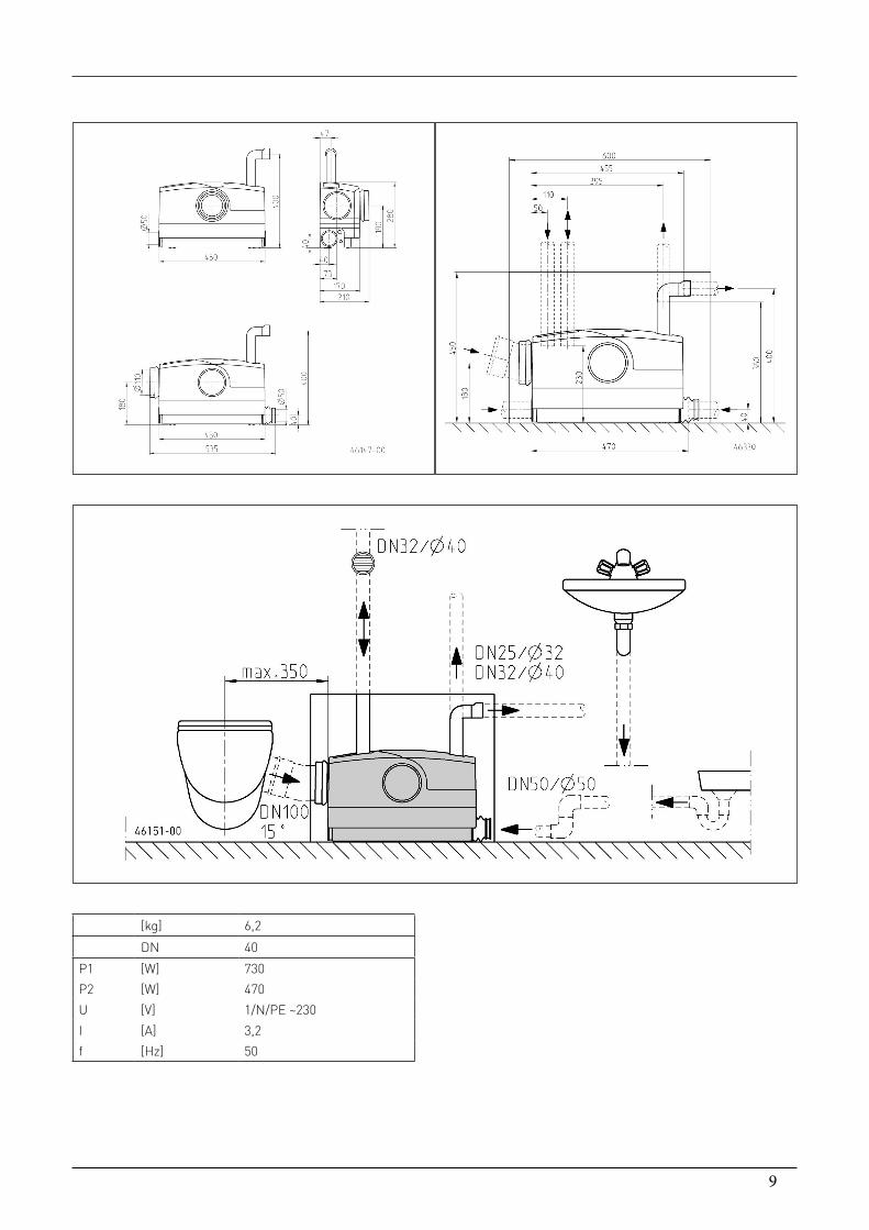
If the toilet is wall-mounted, the WCFIX PLUS is installed immediately adjacent to the toilet module. The unit is con-nected to the outlet bend of the front-wall installation via a 15º bend with a nominal diameter (DN) of 100 mm and high temperature resistance (HT). The WCFIX PLUS can be installed to the left or right of the toilet.
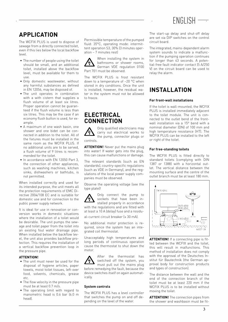
For free-standing toilets
The WCFIX PLUS is fitted directly to standard toilets (complying with DIN 1387 or 1388) with a horizontal out-let. The vertical distance between the mounting surface and the centre of the outlet branch must be at least 180 mm.
ATTENTION! If a connecting pipe is fit-ted between the WCFIX and the toilet, this will result in malfunctions. This method of installation does not comply with the approval of the Deutsches In-stitut für Bautechnik (the German ap-proval body for construction products and types of construction).
The distance between the wall and the end of the connection branch of the toilet must be at least 220 mm if the WCFIX PLUS is to be installed without moving the toilet.
ATTENTION! The connection pipes from the shower and washbasin must be fit-
4
ENGLISHted with a so-called back-up bend, in-stalled as close to the unit as possible. The pipe invert of this bend must be at a height of at least 75 mm above the mounting surface on which the unit is fixed. Air pockets in the connecting pipe can cause run-off problems and the wa-ter could back up. To prevent back-ups, the inlet pipe from the shower must be vented at its highest point. The ventila-tion pipe can be connected into the tank ventilation.
When installing a shower, the priority valve supplied with the unit must be in-serted into the corresponding connec-tion port.
In the case of front-wall installations, the WCFIX PLUS should be installed be-fore the panelling is fixed to the frame. This makes it easier to install the unit and to check the connections.
Instructions regarding ventilation of the tank
ATTENTION!The tank ventilation is es-sential for proper operation of the sys-tem and must be fed out through the front-wall panel. A pipe with a nomi-nal diameter of 40 mm and high tem-perature resistance (not supplied) can be used to connect the system to the ventilation insert (supplied) or to a roof vent. This connection pipe ensures that no damp air can escape from the tank into the room in which the WCFIX PLUS is installed, where it could otherwise cause hidden moisture-related damage or mould growth. An activated carbon filter is supplied with the unit to mini-mise unpleasant odours. The protec-tive film must be removed before use. The filter can be replaced and serviced from outside via the ventilation grille. The ventilation insert can be fixed into the front wall at the top, the side or the front of the wall, if required. However, it must be installed above the height of all of the fixtures that are connected to the WCFIX PLUS.
If the WCFIX PLUS is not installed be-hind a front wall, an activated carbon filter can be fitted at the tank.
ATTENTION! Activated carbon filters reduce unpleasant odours, whereas a roof vent prevents them.
A hole 76 mm in diameter must be drilled for the installation of the venti-lation system.
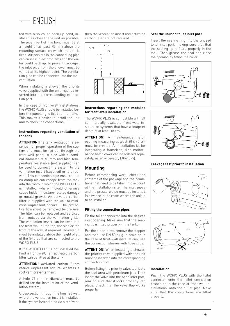
Cross-section through the finished wall where the ventilation insert is installed. If the system is ventilated via a roof vent,
then the ventilation insert and activated carbon filter are not required.
Instructions regarding the modules for front-wall installation
The WCFIX PLUS is compatible with all commercially available front-wall in-stallation systems that have a footprint depth of at least 18 cm.
ATTENTION! A maintenance hatch opening measuring at least 60 x 45 cm must be created. An installation kit for integrating a frameless, tiled mainte-nance hatch cover can be ordered sepa-rately, as an accessory (JP41075).
MountingBefore commencing work, check the contents of the package and the condi-tions that need to be taken into account at the installation site. The inlet pipes and the pressure pipe must be installed in advance in the room where the unit is to be installed.
Fitting the connection pipes
Fit the toilet connector into the desired inlet opening. Make sure that the seal-ing lip is fitted properly in the tank.
For the other inlets, remove the stopper and then use DN 50 plug-in seals or, in the case of front-wall installations, use the connection sleeves with hose clips.
ATTENTION! When installing a shower, the priority valve supplied with the unit must be inserted into the corresponding connection port.
Before fitting the priority valve, lubricate the seal area with petroleum jelly. Then insert the valve into the open inlet port, making sure that it locks properly into place. Check that the valve flap works properly.
Seal the unused toilet inlet port
Insert the sealing ring into the unused toilet inlet port, making sure that that the sealing lip is fitted properly in the tank. Then grease the seal and close the opening by fitting the cover.
Leakage test prior to installation
Installation
Push the WCFIX PLUS with the toilet connector onto the toilet connection branch or, in the case of front-wall in-stallations, onto the outlet pipe. Make sure that the connections are fitted properly.
5
ENGLISHConnect the DN 50 inlet pipes using plug-in seals or, in the case of front-wall installations, with sleeves and clips.
Connect the pressure pipe with the pressure port discharge elbow and hose clips.
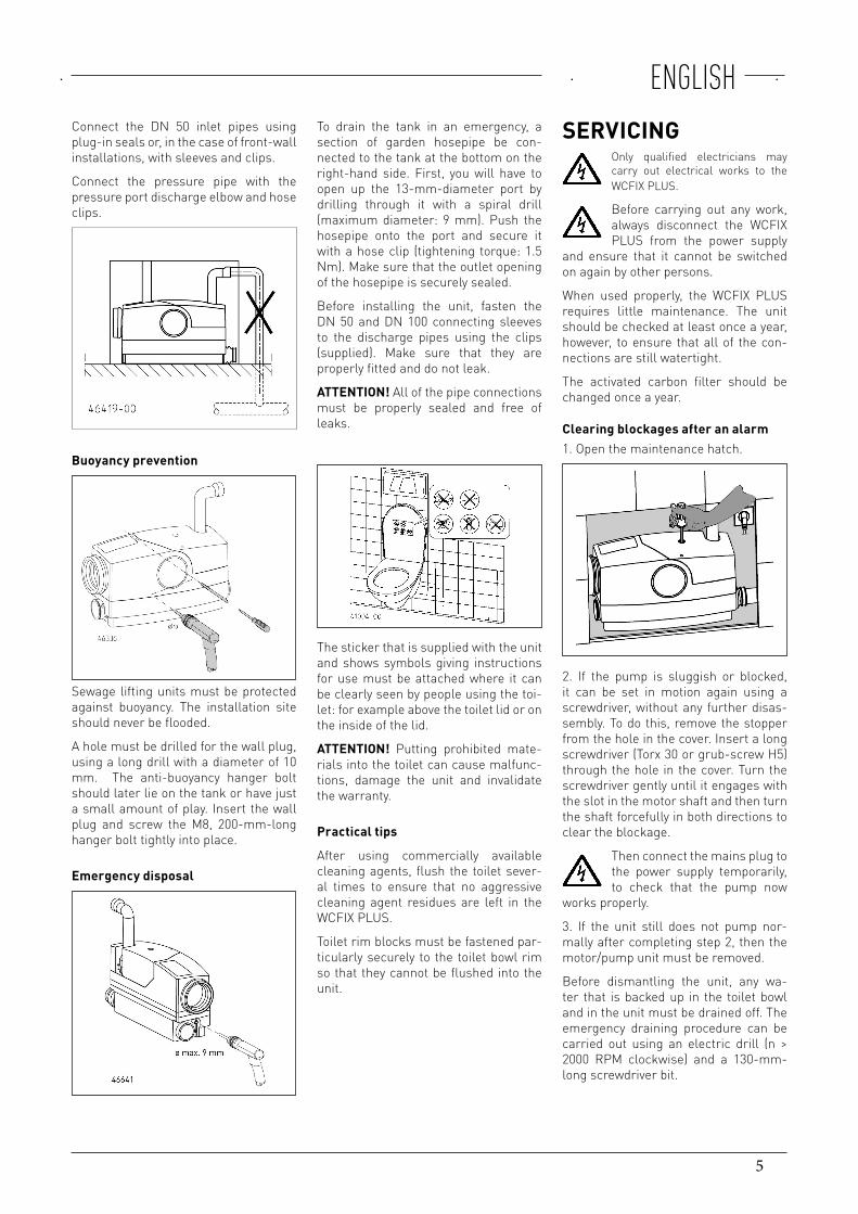
Buoyancy prevention
Sewage lifting units must be protected against buoyancy. The installation site should never be flooded.
A hole must be drilled for the wall plug, using a long drill with a diameter of 10 mm. The anti-buoyancy hanger bolt should later lie on the tank or have just a small amount of play. Insert the wall plug and screw the M8, 200-mm-long hanger bolt tightly into place.
Emergency disposal
To drain the tank in an emergency, a section of garden hosepipe be con-nected to the tank at the bottom on the right-hand side. First, you will have to open up the 13-mm-diameter port by drilling through it with a spiral drill (maximum diameter: 9 mm). Push the hosepipe onto the port and secure it with a hose clip (tightening torque: 1.5 Nm). Make sure that the outlet opening of the hosepipe is securely sealed.
Before installing the unit, fasten the DN 50 and DN 100 connecting sleeves to the discharge pipes using the clips (supplied). Make sure that they are properly fitted and do not leak.
ATTENTION! All of the pipe connections must be properly sealed and free of leaks.
The sticker that is supplied with the unit and shows symbols giving instructions for use must be attached where it can be clearly seen by people using the toi-let: for example above the toilet lid or on the inside of the lid.
ATTENTION! Putting prohibited mate-rials into the toilet can cause malfunc-tions, damage the unit and invalidate the warranty.
Practical tips
After using commercially available cleaning agents, flush the toilet sever-al times to ensure that no aggressive cleaning agent residues are left in the WCFIX PLUS.
Toilet rim blocks must be fastened par-ticularly securely to the toilet bowl rim so that they cannot be flushed into the unit.
SERVICINGOnly qualified electricians may carry out electrical works to the WCFIX PLUS.
Before carrying out any work, always disconnect the WCFIX PLUS from the power supply
and ensure that it cannot be switched on again by other persons.
When used properly, the WCFIX PLUS requires little maintenance. The unit should be checked at least once a year, however, to ensure that all of the con-nections are still watertight.
The activated carbon filter should be changed once a year.
Clearing blockages after an alarm1. Open the maintenance hatch.
2. If the pump is sluggish or blocked,it can be set in motion again using a screwdriver, without any further disas-sembly. To do this, remove the stopper from the hole in the cover. Insert a long screwdriver (Torx 30 or grub-screw H5) through the hole in the cover. Turn the screwdriver gently until it engages with the slot in the motor shaft and then turn the shaft forcefully in both directions to clear the blockage.
Then connect the mains plug to the power supply temporarily, to check that the pump now
works properly.
3. If the unit still does not pump nor-mally after completing step 2, then the motor/pump unit must be removed.
Before dismantling the unit, any wa-ter that is backed up in the toilet bowl and in the unit must be drained off. The emergency draining procedure can be carried out using an electric drill (n > 2000 RPM clockwise) and a 130-mm-long screwdriver bit.
6
ENGLISH
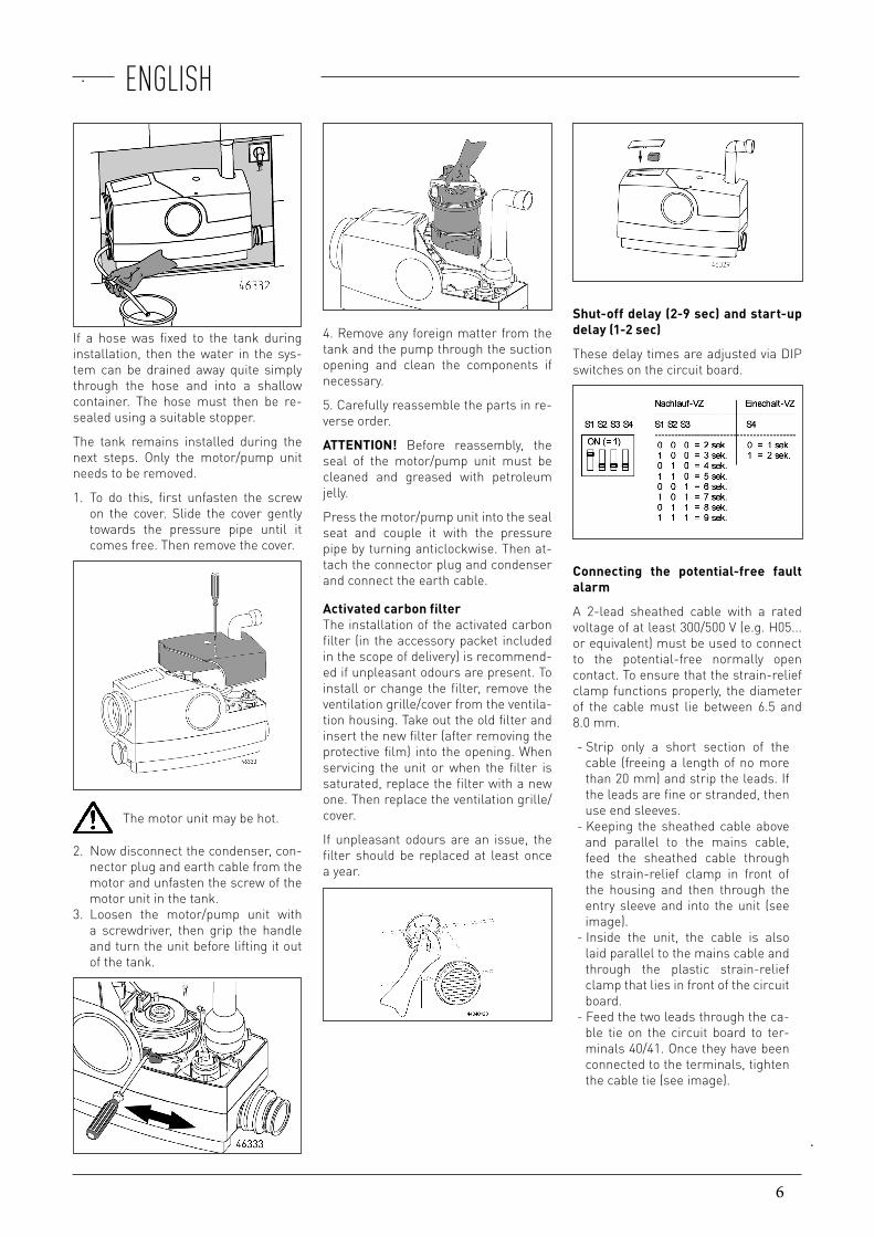
If a hose was fixed to the tank during installation, then the water in the sys-tem can be drained away quite simply through the hose and into a shallow container. The hose must then be re-sealed using a suitable stopper.
The tank remains installed during the next steps. Only the motor/pump unit needs to be removed.
1. To do this, first unfasten the screwon the cover. Slide the cover gentlytowards the pressure pipe until itcomes free. Then remove the cover.
The motor unit may be hot.
2. Now disconnect the condenser, con-nector plug and earth cable from themotor and unfasten the screw of themotor unit in the tank.
3. Loosen the motor/pump unit witha screwdriver, then grip the handleand turn the unit before lifting it outof the tank.
4. Remove any foreign matter from thetank and the pump through the suction opening and clean the components if necessary.
5. Carefully reassemble the parts in re-verse order.
ATTENTION! Before reassembly, the seal of the motor/pump unit must be cleaned and greased with petroleum jelly.
Press the motor/pump unit into the seal seat and couple it with the pressure pipe by turning anticlockwise. Then at-tach the connector plug and condenser and connect the earth cable.
Activated carbon filterThe installation of the activated carbon filter (in the accessory packet included in the scope of delivery) is recommend-ed if unpleasant odours are present. To install or change the filter, remove the ventilation grille/cover from the ventila-tion housing. Take out the old filter and insert the new filter (after removing the protective film) into the opening. When servicing the unit or when the filter is saturated, replace the filter with a new one. Then replace the ventilation grille/cover.
If unpleasant odours are an issue, the filter should be replaced at least once a year.
Shut-off delay (2-9 sec) and start-up delay (1-2 sec)
These delay times are adjusted via DIP switches on the circuit board.
Connecting the potential-free fault alarm
A 2-lead sheathed cable with a rated voltage of at least 300/500 V (e.g. H05... or equivalent) must be used to connect to the potential-free normally open contact. To ensure that the strain-relief clamp functions properly, the diameter of the cable must lie between 6.5 and 8.0 mm.
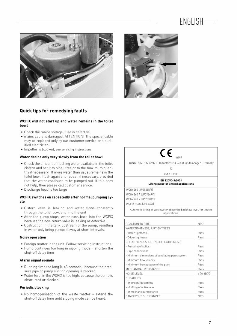
- Strip only a short section of the cable (freeing a length of no more than 20 mm) and strip the leads. If the leads are fine or stranded, then use end sleeves. - Keeping the sheathed cable above and parallel to the mains cable, feed the sheathed cable through the strain-relief clamp in front of the housing and then through the entry sleeve and into the unit (see image). - Inside the unit, the cable is also laid parallel to the mains cable and through the plastic strain-relief clamp that lies in front of the circuit board. - Feed the two leads through the ca-ble tie on the circuit board to ter-minals 40/41. Once they have been connected to the terminals, tighten the cable tie (see image).
7
ENGLISH
Quick tips for remedying faults
WCFIX will not start up and water remains in the toilet bowl
∙ Check the mains voltage, fuse is defective, ∙ mains cable is damaged. ATTENTION! The special cable may be replaced only by our customer service or a qual-ified electrician.
∙ Impeller is blocked, see servicing instructions
Water drains only very slowly from the toilet bowl
∙ Check the amount of flushing water available in the toilet cistern and set it to nine litres or to the maximum quan-tity if necessary. If more water than usual remains in the toilet bowl, flush again and repeat, if necessary, provided that the water continues to be pumped out. If this does not help, then please call customer service.
∙ Discharge head is too large
WCFIX switches on repeatedly after normal pumping cy-cle
∙ Cistern valve is leaking and water flows constantly through the toilet bowl and into the unit
∙ After the pump stops, water runs back into the WCFIX because the non-return valve is leaking or defective.
∙ Obstruction in the tank upstream of the pump, resulting in water only being pumped away at short intervals.
Noisy operation
∙ Foreign matter in the unit. Follow servicing instructions. ∙ Pump continues too long in sipping mode = shorten the shut-off delay time
Alarm signal sounds
∙ Running time too long (> 43 seconds), because the pres-sure pipe or pump suction opening is blocked
∙ Water level in the WCFIX is too high, because the pump is obstructed or blocked
Periodic blocking
∙ No homogenisation of the waste matter = extend the shut-off delay time until sipping mode can be heard.
0197
JUNG PUMPEN GmbH - Industriestr. 4-6 33803 Steinhagen, Germany
13
451.11.1503
EN 12050-3:2001Lifting plant for limited applications
WCfix 260 (JP09268/1)WCfix 260 A (JP09269/1)WCfix 260 V (JP09320/3)WCFIX PLUS (JP45367)
Automatic lifting of wastewater above the backflow level, for limited applications.
REACTION TO FIRE NPDWATERTIGHTNESS, AIRTIGHTNESS- Water tightness Pass- Odour tightness PassEFFECTIVENESS (LIFTING EFFECTIVENESS)- Pumping of solids Pass- Pipe connections Pass- Minimum dimensions of ventilating pipes system Pass- Minimum flow velocity Pass- Minimum free passage of the plant PassMECHANICAL RESISTANCE PassNOISE LEVEL ≤ 70 dB(A)DURABILITY- of structural stability Pass- of lifting effectiveness Pass- of mechanical resistance PassDANGEROUS SUBSTANCES NPD
8
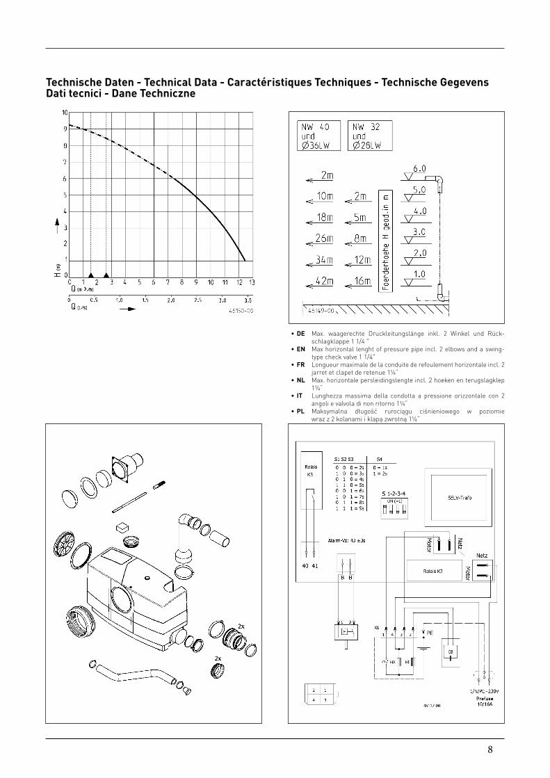
∙ DE Max. waagerechte Druckleitungslänge inkl. 2 Winkel und Rück-schlagklappe 1 1/4 "
∙ EN Max horizontal lenght of pressure pipe incl. 2 elbows and a swing-type check valve 1 1/4"
∙ FR Longueur maximale de la conduite de refoulement horizontale incl. 2 jarret et clapet de retenue 1¼“
∙ NL Max. horizontale persleidingslengte incl. 2 hoeken en terugslagklep 1¼“
∙ IT Lunghezza massima della condotta a pressione orizzontale con 2 angoli e valvola di non ritorno 1¼“
∙ PL Maksymalna długość rurociągu ciśnieniowego w poziomie wraz z 2 kolanami i klapą zwrotną 1¼“
Technische Daten - Technical Data - Caractéristiques Techniques - Technische Gegevens Dati tecnici - Dane Techniczne
9
[kg] 6,2DN 40
P1 [W] 730P2 [W] 470U [V] 1/N/PE ~230I [A] 3,2f [Hz] 50
10
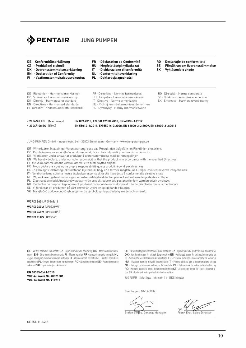
DE Konformitätserklärung CZ · Prohlášeni o shodě DK · Overensstemmelseserklæring EN · Declaration of Conformity FI · Vaatimustenmukaisuusvakuutus
FR · Déclaration de Conformité HU · Megfelelöségi nyilatkozat IT · Dichiarazione di conformità NL · Conformiteitsverklaring PL · Deklaracja zgodności
RO · Declaraţie de conformitate SE · Försäkran om överensstämmelse SK · Vyhlásenie o zhode
JUNG PUMPEN GmbH - Industriestr. 4-6 - 33803 Steinhagen - Germany - www.jung-pumpen.de
DE · Wir erklären in alleiniger Verantwortung, dass das Produkt den aufgeführten Richtlinien entspricht.CZ · Prohlašujeme na svou výlučnou odpovědnost, že výrobek odpovídá jmenovaným směrnicím.DK · Vi erklærer under ansvar at produktet i overensstemmelse med de retningslinjerEN · We hereby declare, under our sole responsibility, that the product is in accordance with the specified Directives.FI · Me vakuutamme omalla vastuullamme, että tuote täyttää ohjeita.FR · Nous déclarons sous notre propre responsabilité que le produit répond aux directives.HU · Kizárólagos felelősségünk tudatában kijelentjük, hogy ez a termék megfelel az Európai Unió fentnevezett irányelveinek.IT · Noi dichiariamo sotto la nostra esclusiva responsabilità che il prodotto è conforme alle direttive citateNL · Wij verklaren geheel onder eigen verantwoordelijkheid dat het product voldoet aan de gestelde richtlijnen.PL · Z pełną odpowiedzialnością oświadczamy, że produkt odpowiada postanowieniom wymienionych dyrektyw.RO · Declarăm pe proprie răspundere că produsul corespunde normelor prevăzute de directivele mai sus menţionate.SE · Vi försäkrar att produkten på vårt ansvar är utförd enligt gällande riktlinjer.SK · Na výlučnú zodpovednosť vyhlasujeme, že výrobok spíňa požiadavky uvedených smerníc.
CE 351-11-1412
Steinhagen, 10-12-2014
______________________ ppa. ____________________Stefan Sirges, General Manager Frank Erdt, Sales Director
DE · Weitere normative Dokumente CZ · Jinými normativními dokumenty DK · Andre normative doku-menter EN · Other normative documents FI · Muiden normien FR · Autres documents normatifs HU · Egyéb szabályozó dokumentumokban leírtaknak IT · Altri documenti normativi NL · Verdere normatieve documenten PL · Innymi dokumentami normatywnymi RO · Alte acte normative SE · Vidare normerande dokument SK · Iným záväzným dokumentom:
EN 60335-2-41:2010VDE-Ausweis Nr. 40021501VDE-Ausweis Nr. 115917
• 2006/42 EG (Machinery) EN 809:2010; EN ISO 12100:2010, EN 60335-1:2012• 2004/108 EG (EMC) EN 55014-1:2011, EN 55014-2:2008, EN 61000-3-2:2009, EN 61000-3-3:2013
DE · Richtlinien - Harmonisierte Normen CZ · Směrnice - Harmonizované normy DK · Direktiv - Harmoniseret standardEN · Directives - Harmonised standards FI · Direktiivi - Yhdenmukaistettu standardi
FR · Directives - Normes harmoniséesHU · Irányelve - Harmonizá szabványokIT · Direttive - Norme armonizzateNL · Richtlijnen - Geharmoniseerde normenPL · Dyrektywy - Normy zharmonizowane
RO · Directivă - Norme coroborateSE · Direktiv - Harmoniserade normerSK · Smernice - Harmonizované normy
WCFIX 260 (JP09268/1)
WCFIX 260 A (JP09269/1)
WCFIX 260 V (JP09320/3)
WCFIX PLUS (JP45367)
DE · Bevollmächtigter für technische Dokumentation CZ · Oprávněná osoba pro technickou dokumentaci DK · Autoriseret person for teknisk dokumentation EN · Authorized person for technical documentation FI · Valtuutettu henkilö tekninen dokumentaatio FR · Personne autorisée à la documentation technique HU · Hivatalos személy műszaki dokumentáció IT · Persona abilitata per la documentazione tecnica NL · Bevoegd persoon voor technische documentatie PL · Pełnomocnik ds. dokumentacji technicznej RO · Persoană autorizată pentru documentatiei tehnice SE · Auktoriserad person för teknisk dokumenta-tion SK · Oprávnená osoba pre technickú dokumentáciu:
JUNG PUMPEN - Stefan Sirges - Industriestr. 4-6 - 33803 Steinhagen

11

JUNG PUMPEN GmbH - Industriestr. 4-6 - 33803 Steinhagen - Deutschland Tel. +49 5204 170 - Fax +49 5204 80368 - eMail [email protected] Technical Services Ltd/Jung Pumpen - Pump House - Unit 12 - Bilton Road Industrial Estate - Erith - Kent - DA8 2AN - United KingdomTel. +44 1322 357 080 - Fax +44 1322 341 341 - eMail: [email protected]