Embed Size (px)
Citation preview
Junos® OS
Junos OS OSPF Configuration Guide
Release
11.4
Published: 2011-11-08
Revision 1
Copyright © 2011, Juniper Networks, Inc.

Juniper Networks, Inc.1194 North Mathilda AvenueSunnyvale, California 94089USA408-745-2000www.juniper.net
This product includes the Envoy SNMP Engine, developed by Epilogue Technology, an Integrated Systems Company. Copyright © 1986-1997,Epilogue Technology Corporation. All rights reserved. This program and its documentation were developed at private expense, and no partof them is in the public domain.
This product includes memory allocation software developed by Mark Moraes, copyright © 1988, 1989, 1993, University of Toronto.
This product includes FreeBSD software developed by the University of California, Berkeley, and its contributors. All of the documentationand software included in the 4.4BSD and 4.4BSD-Lite Releases is copyrighted by the Regents of the University of California. Copyright ©1979, 1980, 1983, 1986, 1988, 1989, 1991, 1992, 1993, 1994. The Regents of the University of California. All rights reserved.
GateD software copyright © 1995, the Regents of the University. All rights reserved. Gate Daemon was originated and developed throughrelease 3.0 by Cornell University and its collaborators. Gated is based on Kirton’s EGP, UC Berkeley’s routing daemon (routed), and DCN’sHELLO routing protocol. Development of Gated has been supported in part by the National Science Foundation. Portions of the GateDsoftware copyright © 1988, Regents of the University of California. All rights reserved. Portions of the GateD software copyright © 1991, D.L. S. Associates.
This product includes software developed by Maker Communications, Inc., copyright © 1996, 1997, Maker Communications, Inc.
Juniper Networks, Junos, Steel-Belted Radius, NetScreen, and ScreenOS are registered trademarks of Juniper Networks, Inc. in the UnitedStates and other countries. The Juniper Networks Logo, the Junos logo, and JunosE are trademarks of Juniper Networks, Inc. All othertrademarks, service marks, registered trademarks, or registered service marks are the property of their respective owners.
Juniper Networks assumes no responsibility for any inaccuracies in this document. Juniper Networks reserves the right to change, modify,transfer, or otherwise revise this publication without notice.
Products made or sold by Juniper Networks or components thereof might be covered by one or more of the following patents that areowned by or licensed to Juniper Networks: U.S. Patent Nos. 5,473,599, 5,905,725, 5,909,440, 6,192,051, 6,333,650, 6,359,479, 6,406,312,6,429,706, 6,459,579, 6,493,347, 6,538,518, 6,538,899, 6,552,918, 6,567,902, 6,578,186, and 6,590,785.
Junos®OS Junos OS OSPF Configuration Guide
Copyright © 2011, Juniper Networks, Inc.All rights reserved.
Revision HistoryNovember 2011—Revision 1; initial release
The information in this document is current as of the date listed in the revision history.
ENDUSER LICENSE AGREEMENT
The Juniper Networks product that is the subject of this technical documentation consists of (or is intended for use with) Juniper Networkssoftware. Use of such software is subject to the terms and conditions of the End User License Agreement (“EULA”) posted at
http://www.juniper.net/support/eula.html. By downloading, installing or using such software, you agree to the terms and conditionsof that EULA.
Copyright © 2011, Juniper Networks, Inc.ii
Table of Contents
Part 1 Overview
Chapter 1 Introduction to OSPF . . . . . . . . . . . . . . . . . . . . . . . . . . . . . . . . . . . . . . . . . . . . . . . 3
OSPF Overview . . . . . . . . . . . . . . . . . . . . . . . . . . . . . . . . . . . . . . . . . . . . . . . . . . . . . 4
OSPF Default Route Preference Values . . . . . . . . . . . . . . . . . . . . . . . . . . . . . . . 5
OSPF Routing Algorithm . . . . . . . . . . . . . . . . . . . . . . . . . . . . . . . . . . . . . . . . . . . 5
OSPF Three-Way Handshake . . . . . . . . . . . . . . . . . . . . . . . . . . . . . . . . . . . . . . . 6
OSPF Version 3 . . . . . . . . . . . . . . . . . . . . . . . . . . . . . . . . . . . . . . . . . . . . . . . . . . 7
OSPF Areas and Router Functionality Overview . . . . . . . . . . . . . . . . . . . . . . . . . . . . 8
Areas . . . . . . . . . . . . . . . . . . . . . . . . . . . . . . . . . . . . . . . . . . . . . . . . . . . . . . . . . . 8
Area Border Routers . . . . . . . . . . . . . . . . . . . . . . . . . . . . . . . . . . . . . . . . . . . . . . 8
Backbone Areas . . . . . . . . . . . . . . . . . . . . . . . . . . . . . . . . . . . . . . . . . . . . . . . . . 8
AS Boundary Routers . . . . . . . . . . . . . . . . . . . . . . . . . . . . . . . . . . . . . . . . . . . . . 9
Backbone Router . . . . . . . . . . . . . . . . . . . . . . . . . . . . . . . . . . . . . . . . . . . . . . . . 9
Internal Router . . . . . . . . . . . . . . . . . . . . . . . . . . . . . . . . . . . . . . . . . . . . . . . . . . 9
Stub Areas . . . . . . . . . . . . . . . . . . . . . . . . . . . . . . . . . . . . . . . . . . . . . . . . . . . . . . 9
Not-So-Stubby Areas . . . . . . . . . . . . . . . . . . . . . . . . . . . . . . . . . . . . . . . . . . . . 10
Transit Areas . . . . . . . . . . . . . . . . . . . . . . . . . . . . . . . . . . . . . . . . . . . . . . . . . . . 10
Packets Overview . . . . . . . . . . . . . . . . . . . . . . . . . . . . . . . . . . . . . . . . . . . . . . . . . . . 10
OSPF Packet Header . . . . . . . . . . . . . . . . . . . . . . . . . . . . . . . . . . . . . . . . . . . . . 10
Hello Packets . . . . . . . . . . . . . . . . . . . . . . . . . . . . . . . . . . . . . . . . . . . . . . . . . . . 11
Database Description Packets . . . . . . . . . . . . . . . . . . . . . . . . . . . . . . . . . . . . . . 11
Link-State Request Packets . . . . . . . . . . . . . . . . . . . . . . . . . . . . . . . . . . . . . . . . 11
Link-State Update Packets . . . . . . . . . . . . . . . . . . . . . . . . . . . . . . . . . . . . . . . . 12
Link-State Acknowledgment Packets . . . . . . . . . . . . . . . . . . . . . . . . . . . . . . . . 12
Link-State Advertisement Packet Types . . . . . . . . . . . . . . . . . . . . . . . . . . . . . . 12
OSPF External Metrics Overview . . . . . . . . . . . . . . . . . . . . . . . . . . . . . . . . . . . . . . . 13
OSPF Designated Router Overview . . . . . . . . . . . . . . . . . . . . . . . . . . . . . . . . . . . . . 13
OSPF Extensions to Support Traffic Engineering . . . . . . . . . . . . . . . . . . . . . . . . . . 14
OSPF IGP Shortcuts . . . . . . . . . . . . . . . . . . . . . . . . . . . . . . . . . . . . . . . . . . . . . 14
OSPF Database Protection Overview . . . . . . . . . . . . . . . . . . . . . . . . . . . . . . . . . . . 15
Chapter 2 Introduction to OSPF Configuration Guidelines . . . . . . . . . . . . . . . . . . . . . . . . 17
BFD Authentication for OSPF Overview . . . . . . . . . . . . . . . . . . . . . . . . . . . . . . . . . . 17
BFD Authentication Algorithms . . . . . . . . . . . . . . . . . . . . . . . . . . . . . . . . . . . . . 17
Security Authentication Keychains . . . . . . . . . . . . . . . . . . . . . . . . . . . . . . . . . . 18
Strict Versus Loose Authentication . . . . . . . . . . . . . . . . . . . . . . . . . . . . . . . . . . 18
Loop-Free Alternate Routes for OSPF Overview . . . . . . . . . . . . . . . . . . . . . . . . . . . 19
iiiCopyright © 2011, Juniper Networks, Inc.
Part 2 Configuration
Chapter 3 OSPF Configuration Guidelines . . . . . . . . . . . . . . . . . . . . . . . . . . . . . . . . . . . . . 23
Configuring OSPF . . . . . . . . . . . . . . . . . . . . . . . . . . . . . . . . . . . . . . . . . . . . . . . . . . . 24
Minimum OSPF Configuration . . . . . . . . . . . . . . . . . . . . . . . . . . . . . . . . . . . . . . . . . 29
Configuring OSPF Areas . . . . . . . . . . . . . . . . . . . . . . . . . . . . . . . . . . . . . . . . . . . . . . 29
Configuring the OSPF Backbone Area . . . . . . . . . . . . . . . . . . . . . . . . . . . . . . . 30
Configuring OSPF Nonbackbone Areas . . . . . . . . . . . . . . . . . . . . . . . . . . . . . . 30
Configuring OSPF Stub Areas . . . . . . . . . . . . . . . . . . . . . . . . . . . . . . . . . . . . . 30
Configuring OSPF Not-So-Stubby Areas . . . . . . . . . . . . . . . . . . . . . . . . . . . . . 31
Configuring OSPF Virtual Links . . . . . . . . . . . . . . . . . . . . . . . . . . . . . . . . . . . . . 32
Example: Configuring an OSPF Virtual Link . . . . . . . . . . . . . . . . . . . . . . . 32
Disabling Export of LSAs into NSSAs Attached to ASBR ABRs . . . . . . . . . . . . . . . 33
Example: Disabling OSPFv2 Compatibility with RFC 1583 . . . . . . . . . . . . . . . . . . . 33
Configuring OSPF on Interfaces . . . . . . . . . . . . . . . . . . . . . . . . . . . . . . . . . . . . . . . 34
Configuring an Interface on a Broadcast or Point-to-Point Network . . . . . . . 35
Configuring an Interface on a Point-to-Multipoint Network . . . . . . . . . . . . . . 35
Configuring an Interface on a Nonbroadcast, Multiaccess Network . . . . . . . . 36
Configuring an OSPF Demand Circuit Interface . . . . . . . . . . . . . . . . . . . . . . . . 37
Example: Configuring Multiarea Adjacency for OSPF . . . . . . . . . . . . . . . . . . . . . . . 37
Example: Configuring Multiple Address Families for OSPFv3 . . . . . . . . . . . . . . . . . 41
Configuring Authentication for OSPFv2 . . . . . . . . . . . . . . . . . . . . . . . . . . . . . . . . . 44
Example: Configuring IPsec Authentication for an OSPFv2 Interface . . . . . . 46
Example: Configuring a Transition of MD5 Keys . . . . . . . . . . . . . . . . . . . . . . . 47
Example: Configuring MD5 Authentication . . . . . . . . . . . . . . . . . . . . . . . . . . . 47
Configuring Authentication for OSPFv3 . . . . . . . . . . . . . . . . . . . . . . . . . . . . . . . . . 48
Example: Limiting the Number of Prefixes Exported to OSPF . . . . . . . . . . . . . . . . 48
Example: Controlling OSPF Designated Router Election . . . . . . . . . . . . . . . . . . . . 50
Example: Summarizing Ranges of Routes in OSPF Link-State
Advertisements . . . . . . . . . . . . . . . . . . . . . . . . . . . . . . . . . . . . . . . . . . . . . . . . . 52
Example: Controlling the Cost of Individual OSPF Network Segments . . . . . . . . . 57
Example: Dynamically Adjusting OSPF Interface Metrics Based on
Bandwidth . . . . . . . . . . . . . . . . . . . . . . . . . . . . . . . . . . . . . . . . . . . . . . . . . . . . . 61
Example: Controlling OSPF Route Preferences . . . . . . . . . . . . . . . . . . . . . . . . . . . 63
Example: Configuring OSPF Timers . . . . . . . . . . . . . . . . . . . . . . . . . . . . . . . . . . . . 66
Configuring OSPF Refresh and Flooding Reduction in Stable Topologies . . . . . . . 71
Example: Configuring BFD for OSPF . . . . . . . . . . . . . . . . . . . . . . . . . . . . . . . . . . . . 72
Configuring BFD Authentication for OSPF . . . . . . . . . . . . . . . . . . . . . . . . . . . . . . . 76
Configuring BFD Authentication Parameters . . . . . . . . . . . . . . . . . . . . . . . . . . 76
Viewing Authentication Information for BFD Sessions . . . . . . . . . . . . . . . . . . 78
Example: Configuring Synchronization Between LDP and IGPs . . . . . . . . . . . . . . . 79
Example: Configuring Graceful Restart for OSPF . . . . . . . . . . . . . . . . . . . . . . . . . . 82
Example: Configuring SPF Algorithm Options for OSPF . . . . . . . . . . . . . . . . . . . . 86
Example: Configuring a Passive OSPF Interface . . . . . . . . . . . . . . . . . . . . . . . . . . 89
Example: Configuring OSPF Passive Traffic Engineering Mode . . . . . . . . . . . . . . . 91
Example: Advertising Label-Switched Paths into OSPFv2 . . . . . . . . . . . . . . . . . . 93
Example: Configuring OSPF to Make Routing Devices Appear Overloaded . . . . 104
Example: Enabling OSPF Traffic Engineering Support . . . . . . . . . . . . . . . . . . . . . 107
Copyright © 2011, Juniper Networks, Inc.iv
Junos OS OSPF Configuration Guide
Example: Configuring the Traffic Engineering Metric for a Specific OSPF
Interface . . . . . . . . . . . . . . . . . . . . . . . . . . . . . . . . . . . . . . . . . . . . . . . . . . . . . . 112
Applying Policies to OSPF Routes . . . . . . . . . . . . . . . . . . . . . . . . . . . . . . . . . . . . . . 114
Configuring Import and Export Policies for Network Summaries . . . . . . . . . . 114
Configuring Priority for Prefixes in Import Policy . . . . . . . . . . . . . . . . . . . . . . . 115
Example: Configuring a Route Filter Policy to Specify Priority for Prefixes
Learned Through OSPF . . . . . . . . . . . . . . . . . . . . . . . . . . . . . . . . . . . . . . . 116
Configuring OSPF Routing Table Groups . . . . . . . . . . . . . . . . . . . . . . . . . . . . . . . . 117
Example: Configuring OSPFv2 Sham Links . . . . . . . . . . . . . . . . . . . . . . . . . . . . . . . 117
Example: Configuring OSPFv2 Peer interfaces . . . . . . . . . . . . . . . . . . . . . . . . . . . 123
Configuring Link Protection for OSPF . . . . . . . . . . . . . . . . . . . . . . . . . . . . . . . . . . . 124
Configuring Node-Link Protection for OSPF . . . . . . . . . . . . . . . . . . . . . . . . . . . . . 125
Excluding an OSPF Interface as a Backup for a Protected Interface . . . . . . . . . . 126
Configuring Backup SPF Options for Protected OSPF Interfaces . . . . . . . . . . . . . 127
Configuring RSVP Label-Switched Paths as Backup Paths for OSPF . . . . . . . . . 129
Example: Tracing OSPF Protocol Traffic . . . . . . . . . . . . . . . . . . . . . . . . . . . . . . . . 130
Configuring OSPF Database Protection . . . . . . . . . . . . . . . . . . . . . . . . . . . . . . . . . 135
Part 3 Administration
Chapter 4 Summary of OSPF Configuration Statements . . . . . . . . . . . . . . . . . . . . . . . . 139
area . . . . . . . . . . . . . . . . . . . . . . . . . . . . . . . . . . . . . . . . . . . . . . . . . . . . . . . . . . . . . 140
area-range . . . . . . . . . . . . . . . . . . . . . . . . . . . . . . . . . . . . . . . . . . . . . . . . . . . . . . . . 141
authentication . . . . . . . . . . . . . . . . . . . . . . . . . . . . . . . . . . . . . . . . . . . . . . . . . . . . . 142
backup-spf-options . . . . . . . . . . . . . . . . . . . . . . . . . . . . . . . . . . . . . . . . . . . . . . . . 143
bandwidth-based-metrics . . . . . . . . . . . . . . . . . . . . . . . . . . . . . . . . . . . . . . . . . . . 144
bfd-liveness-detection . . . . . . . . . . . . . . . . . . . . . . . . . . . . . . . . . . . . . . . . . . . . . . 146
database-protection . . . . . . . . . . . . . . . . . . . . . . . . . . . . . . . . . . . . . . . . . . . . . . . 150
dead-interval . . . . . . . . . . . . . . . . . . . . . . . . . . . . . . . . . . . . . . . . . . . . . . . . . . . . . . 152
default-lsa . . . . . . . . . . . . . . . . . . . . . . . . . . . . . . . . . . . . . . . . . . . . . . . . . . . . . . . . 153
default-metric . . . . . . . . . . . . . . . . . . . . . . . . . . . . . . . . . . . . . . . . . . . . . . . . . . . . . 154
demand-circuit . . . . . . . . . . . . . . . . . . . . . . . . . . . . . . . . . . . . . . . . . . . . . . . . . . . . 155
disable (LDP Synchronization) . . . . . . . . . . . . . . . . . . . . . . . . . . . . . . . . . . . . . . . 156
disable (OSPF) . . . . . . . . . . . . . . . . . . . . . . . . . . . . . . . . . . . . . . . . . . . . . . . . . . . . 157
domain-id . . . . . . . . . . . . . . . . . . . . . . . . . . . . . . . . . . . . . . . . . . . . . . . . . . . . . . . . 158
domain-vpn-tag . . . . . . . . . . . . . . . . . . . . . . . . . . . . . . . . . . . . . . . . . . . . . . . . . . . 158
export . . . . . . . . . . . . . . . . . . . . . . . . . . . . . . . . . . . . . . . . . . . . . . . . . . . . . . . . . . . 159
external-preference . . . . . . . . . . . . . . . . . . . . . . . . . . . . . . . . . . . . . . . . . . . . . . . . 160
flood-reduction . . . . . . . . . . . . . . . . . . . . . . . . . . . . . . . . . . . . . . . . . . . . . . . . . . . . 161
graceful-restart . . . . . . . . . . . . . . . . . . . . . . . . . . . . . . . . . . . . . . . . . . . . . . . . . . . . 162
hello-interval . . . . . . . . . . . . . . . . . . . . . . . . . . . . . . . . . . . . . . . . . . . . . . . . . . . . . . 164
hold-time . . . . . . . . . . . . . . . . . . . . . . . . . . . . . . . . . . . . . . . . . . . . . . . . . . . . . . . . 165
ignore-lsp-metrics . . . . . . . . . . . . . . . . . . . . . . . . . . . . . . . . . . . . . . . . . . . . . . . . . 165
import . . . . . . . . . . . . . . . . . . . . . . . . . . . . . . . . . . . . . . . . . . . . . . . . . . . . . . . . . . . 166
inter-area-prefix-export . . . . . . . . . . . . . . . . . . . . . . . . . . . . . . . . . . . . . . . . . . . . . 167
inter-area-prefix-import . . . . . . . . . . . . . . . . . . . . . . . . . . . . . . . . . . . . . . . . . . . . . 168
interface . . . . . . . . . . . . . . . . . . . . . . . . . . . . . . . . . . . . . . . . . . . . . . . . . . . . . . . . . 169
interface-type . . . . . . . . . . . . . . . . . . . . . . . . . . . . . . . . . . . . . . . . . . . . . . . . . . . . . . 171
ipsec-sa . . . . . . . . . . . . . . . . . . . . . . . . . . . . . . . . . . . . . . . . . . . . . . . . . . . . . . . . . . 173
vCopyright © 2011, Juniper Networks, Inc.
Table of Contents
label-switched-path . . . . . . . . . . . . . . . . . . . . . . . . . . . . . . . . . . . . . . . . . . . . . . . . 174
ldp-synchronization . . . . . . . . . . . . . . . . . . . . . . . . . . . . . . . . . . . . . . . . . . . . . . . . 175
link-protection . . . . . . . . . . . . . . . . . . . . . . . . . . . . . . . . . . . . . . . . . . . . . . . . . . . . . 176
lsp-metric-into-summary . . . . . . . . . . . . . . . . . . . . . . . . . . . . . . . . . . . . . . . . . . . . 177
md5 . . . . . . . . . . . . . . . . . . . . . . . . . . . . . . . . . . . . . . . . . . . . . . . . . . . . . . . . . . . . . 178
metric . . . . . . . . . . . . . . . . . . . . . . . . . . . . . . . . . . . . . . . . . . . . . . . . . . . . . . . . . . . 179
metric-type . . . . . . . . . . . . . . . . . . . . . . . . . . . . . . . . . . . . . . . . . . . . . . . . . . . . . . . 181
neighbor . . . . . . . . . . . . . . . . . . . . . . . . . . . . . . . . . . . . . . . . . . . . . . . . . . . . . . . . . 182
network-summary-export . . . . . . . . . . . . . . . . . . . . . . . . . . . . . . . . . . . . . . . . . . . 183
network-summary-import . . . . . . . . . . . . . . . . . . . . . . . . . . . . . . . . . . . . . . . . . . . 184
no-domain-vpn-tag . . . . . . . . . . . . . . . . . . . . . . . . . . . . . . . . . . . . . . . . . . . . . . . . 184
no-eligible-backup . . . . . . . . . . . . . . . . . . . . . . . . . . . . . . . . . . . . . . . . . . . . . . . . . 185
no-interface-state-traps . . . . . . . . . . . . . . . . . . . . . . . . . . . . . . . . . . . . . . . . . . . . 186
no-neighbor-down-notification . . . . . . . . . . . . . . . . . . . . . . . . . . . . . . . . . . . . . . . 186
no-nssa-abr . . . . . . . . . . . . . . . . . . . . . . . . . . . . . . . . . . . . . . . . . . . . . . . . . . . . . . 187
no-rfc-1583 . . . . . . . . . . . . . . . . . . . . . . . . . . . . . . . . . . . . . . . . . . . . . . . . . . . . . . . 188
node-link-protection . . . . . . . . . . . . . . . . . . . . . . . . . . . . . . . . . . . . . . . . . . . . . . . 189
nssa . . . . . . . . . . . . . . . . . . . . . . . . . . . . . . . . . . . . . . . . . . . . . . . . . . . . . . . . . . . . . 190
ospf . . . . . . . . . . . . . . . . . . . . . . . . . . . . . . . . . . . . . . . . . . . . . . . . . . . . . . . . . . . . . 191
ospf3 . . . . . . . . . . . . . . . . . . . . . . . . . . . . . . . . . . . . . . . . . . . . . . . . . . . . . . . . . . . . 192
overload . . . . . . . . . . . . . . . . . . . . . . . . . . . . . . . . . . . . . . . . . . . . . . . . . . . . . . . . . 193
passive . . . . . . . . . . . . . . . . . . . . . . . . . . . . . . . . . . . . . . . . . . . . . . . . . . . . . . . . . . 195
peer-interface . . . . . . . . . . . . . . . . . . . . . . . . . . . . . . . . . . . . . . . . . . . . . . . . . . . . . 196
poll-interval . . . . . . . . . . . . . . . . . . . . . . . . . . . . . . . . . . . . . . . . . . . . . . . . . . . . . . . 197
preference . . . . . . . . . . . . . . . . . . . . . . . . . . . . . . . . . . . . . . . . . . . . . . . . . . . . . . . . 198
prefix-export-limit . . . . . . . . . . . . . . . . . . . . . . . . . . . . . . . . . . . . . . . . . . . . . . . . . 199
priority . . . . . . . . . . . . . . . . . . . . . . . . . . . . . . . . . . . . . . . . . . . . . . . . . . . . . . . . . . 200
realm . . . . . . . . . . . . . . . . . . . . . . . . . . . . . . . . . . . . . . . . . . . . . . . . . . . . . . . . . . . . 201
reference-bandwidth . . . . . . . . . . . . . . . . . . . . . . . . . . . . . . . . . . . . . . . . . . . . . . . 202
retransmit-interval . . . . . . . . . . . . . . . . . . . . . . . . . . . . . . . . . . . . . . . . . . . . . . . . . 203
rib-group . . . . . . . . . . . . . . . . . . . . . . . . . . . . . . . . . . . . . . . . . . . . . . . . . . . . . . . . 204
route-type-community . . . . . . . . . . . . . . . . . . . . . . . . . . . . . . . . . . . . . . . . . . . . . 205
secondary . . . . . . . . . . . . . . . . . . . . . . . . . . . . . . . . . . . . . . . . . . . . . . . . . . . . . . . . 205
sham-link . . . . . . . . . . . . . . . . . . . . . . . . . . . . . . . . . . . . . . . . . . . . . . . . . . . . . . . . 206
sham-link-remote . . . . . . . . . . . . . . . . . . . . . . . . . . . . . . . . . . . . . . . . . . . . . . . . . 206
shortcuts . . . . . . . . . . . . . . . . . . . . . . . . . . . . . . . . . . . . . . . . . . . . . . . . . . . . . . . . . 207
simple-password . . . . . . . . . . . . . . . . . . . . . . . . . . . . . . . . . . . . . . . . . . . . . . . . . . 208
spf-options . . . . . . . . . . . . . . . . . . . . . . . . . . . . . . . . . . . . . . . . . . . . . . . . . . . . . . 209
stub . . . . . . . . . . . . . . . . . . . . . . . . . . . . . . . . . . . . . . . . . . . . . . . . . . . . . . . . . . . . . . 211
summaries . . . . . . . . . . . . . . . . . . . . . . . . . . . . . . . . . . . . . . . . . . . . . . . . . . . . . . . . 212
te-metric . . . . . . . . . . . . . . . . . . . . . . . . . . . . . . . . . . . . . . . . . . . . . . . . . . . . . . . . . 213
traceoptions . . . . . . . . . . . . . . . . . . . . . . . . . . . . . . . . . . . . . . . . . . . . . . . . . . . . . . 214
traffic-engineering (OSPF) . . . . . . . . . . . . . . . . . . . . . . . . . . . . . . . . . . . . . . . . . . . 217
traffic-engineering (Passive TE Mode) . . . . . . . . . . . . . . . . . . . . . . . . . . . . . . . . . 219
transit-delay . . . . . . . . . . . . . . . . . . . . . . . . . . . . . . . . . . . . . . . . . . . . . . . . . . . . . . 220
transmit-interval . . . . . . . . . . . . . . . . . . . . . . . . . . . . . . . . . . . . . . . . . . . . . . . . . . . 221
type-7 . . . . . . . . . . . . . . . . . . . . . . . . . . . . . . . . . . . . . . . . . . . . . . . . . . . . . . . . . . . 222
virtual-link . . . . . . . . . . . . . . . . . . . . . . . . . . . . . . . . . . . . . . . . . . . . . . . . . . . . . . . . 223
Copyright © 2011, Juniper Networks, Inc.vi
Junos OS OSPF Configuration Guide
Chapter 5 OSPF Reference . . . . . . . . . . . . . . . . . . . . . . . . . . . . . . . . . . . . . . . . . . . . . . . . . 225
OSPF Standards . . . . . . . . . . . . . . . . . . . . . . . . . . . . . . . . . . . . . . . . . . . . . . . . . . . 225
Part 4 Index
Index . . . . . . . . . . . . . . . . . . . . . . . . . . . . . . . . . . . . . . . . . . . . . . . . . . . . . . . . . . . . 229
viiCopyright © 2011, Juniper Networks, Inc.
Table of Contents

Copyright © 2011, Juniper Networks, Inc.viii
Junos OS OSPF Configuration Guide
List of Figures
Part 1 Overview
Chapter 1 Introduction to OSPF . . . . . . . . . . . . . . . . . . . . . . . . . . . . . . . . . . . . . . . . . . . . . . . 3
Figure 1: OSPF Three-Way Handshake . . . . . . . . . . . . . . . . . . . . . . . . . . . . . . . . . . . 6
Part 2 Configuration
Chapter 3 OSPF Configuration Guidelines . . . . . . . . . . . . . . . . . . . . . . . . . . . . . . . . . . . . . 23
Figure 2: IPv4 Unicast Realm . . . . . . . . . . . . . . . . . . . . . . . . . . . . . . . . . . . . . . . . . . 42
Figure 3: Summarizing Ranges of Routes in OSPF . . . . . . . . . . . . . . . . . . . . . . . . . 53
Figure 4: OSPF Metric Configuration . . . . . . . . . . . . . . . . . . . . . . . . . . . . . . . . . . . . 59
Figure 5: Advertising an LSP into OSPFv2 . . . . . . . . . . . . . . . . . . . . . . . . . . . . . . . . 95
Figure 6: OSPFv2 Sham Link Example . . . . . . . . . . . . . . . . . . . . . . . . . . . . . . . . . . 118
ixCopyright © 2011, Juniper Networks, Inc.

Copyright © 2011, Juniper Networks, Inc.x
Junos OS OSPF Configuration Guide
List of Tables
Part 1 Overview
Chapter 1 Introduction to OSPF . . . . . . . . . . . . . . . . . . . . . . . . . . . . . . . . . . . . . . . . . . . . . . . 3
Table 1: Default Route Preference Values for OSPF . . . . . . . . . . . . . . . . . . . . . . . . . 5
xiCopyright © 2011, Juniper Networks, Inc.

Copyright © 2011, Juniper Networks, Inc.xii
Junos OS OSPF Configuration Guide

PART 1
Overview
• Introduction to OSPF on page 3
• Introduction to OSPF Configuration Guidelines on page 17
1Copyright © 2011, Juniper Networks, Inc.

Copyright © 2011, Juniper Networks, Inc.2
Junos OS OSPF Configuration Guide
CHAPTER 1
Introduction to OSPF
• OSPF Overview on page 4
• OSPF Areas and Router Functionality Overview on page 8
• Packets Overview on page 10
• OSPF External Metrics Overview on page 13
• OSPF Designated Router Overview on page 13
• OSPF Extensions to Support Traffic Engineering on page 14
• OSPF Database Protection Overview on page 15
3Copyright © 2011, Juniper Networks, Inc.
OSPFOverview
OSPF is an interior gateway protocol (IGP) that routes packets within a single autonomous
system (AS). OSPF uses link-state information to make routing decisions, making route
calculations using the shortest-path-first (SPF) algorithm (also referred to as the Dijkstra
algorithm). Each router running OSPF floods link-state advertisements throughout the
AS or area that contain information about that router’s attached interfaces and routing
metrics. Each router uses the information in these link-state advertisements to calculate
the least cost path to each network and create a routing table for the protocol.
Junos OS supports OSPF version 2 (OSPFv2) and OSPF version 3 (OSPFv3), including
virtual links, stub areas, and for OSPFv2, authentication. Junos OS does not support
type-of-service (ToS) routing.
OSPF was designed for the Transmission Control Protocol/Internet Protocol (TCP/IP)
environment and as a result explicitly supports IP subnetting and the tagging of externally
derived routing information. OSPF also provides for the authentication of routing updates.
OSPF routes IP packets based solely on the destination IP address contained in the IP
packet header. OSPF quickly detects topological changes, such as when router interfaces
become unavailable, and calculates new loop-free routes quickly and with a minimum
of routing overhead traffic.
An OSPF AS can consist of a single area, or it can be subdivided into multiple areas. In a
single-area OSPF network topology, each router maintains a database that describes
the topology of the AS. Link-state information for each router is flooded throughout the
AS. In a multiarea OSPF topology, each router maintains a database that describes the
topology of its area, and link-state information for each router is flooded throughout that
area. All routers maintain summarized topologies of other areas within an AS. Within
each area, OSPF routers have identical topological databases. When the AS or area
topology changes, OSPF ensures that the contents of all routers’ topological databases
converge quickly.
All OSPFv2 protocol exchanges can be authenticated. OSPFv3 relies on IPsec to provide
this functionality. This means that only trusted routers can participate in the AS’s routing.
A variety of authentication schemes can be used. A single authentication scheme is
configured for each area, which enables some areas to use stricter authentication than
others.
Externally derived routing data (for example, routes learned from BGP) is passed
transparently throughout the AS. This externally derived data is kept separate from the
OSPF link-state data. Each external route can be tagged by the advertising router, enabling
the passing of additional information between routers on the boundaries of the AS.
NOTE: By default, Junos OS is compatible with RFC 1583,OSPF Version 2. InJunos OS Release 8.5 and later, you can disable compatibility with RFC 1583by including the no-rfc-1583 statement. Formore information, see “Example:
Disabling OSPFv2 Compatibility with RFC 1583” on page 33.
Copyright © 2011, Juniper Networks, Inc.4
Junos OS OSPF Configuration Guide
This topic describes the following information:
• OSPF Default Route Preference Values on page 5
• OSPF Routing Algorithm on page 5
• OSPF Three-Way Handshake on page 6
• OSPF Version 3 on page 7
OSPF Default Route Preference Values
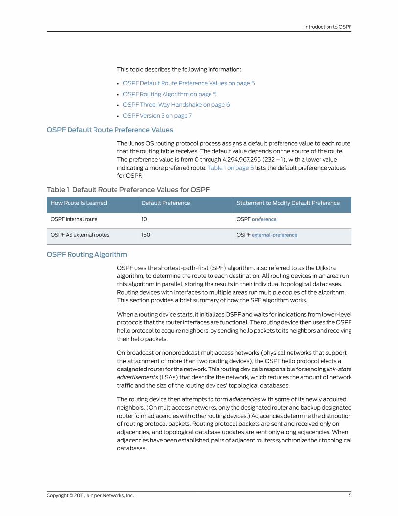
The Junos OS routing protocol process assigns a default preference value to each route
that the routing table receives. The default value depends on the source of the route.
The preference value is from 0 through 4,294,967,295 (232 – 1), with a lower value
indicating a more preferred route. Table 1 on page 5 lists the default preference values
for OSPF.
Table 1: Default Route Preference Values for OSPF
Statement to Modify Default PreferenceDefault PreferenceHow Route Is Learned
OSPF preference10OSPF internal route
OSPF external-preference150OSPF AS external routes
OSPF Routing Algorithm
OSPF uses the shortest-path-first (SPF) algorithm, also referred to as the Dijkstra
algorithm, to determine the route to each destination. All routing devices in an area run
this algorithm in parallel, storing the results in their individual topological databases.
Routing devices with interfaces to multiple areas run multiple copies of the algorithm.
This section provides a brief summary of how the SPF algorithm works.
When a routing device starts, it initializes OSPF and waits for indications from lower-level
protocols that the router interfaces are functional. The routing device then uses the OSPF
hello protocol to acquire neighbors, by sending hello packets to its neighbors and receiving
their hello packets.
On broadcast or nonbroadcast multiaccess networks (physical networks that support
the attachment of more than two routing devices), the OSPF hello protocol elects a
designated router for the network. This routing device is responsible for sending link-state
advertisements (LSAs) that describe the network, which reduces the amount of network
traffic and the size of the routing devices’ topological databases.
The routing device then attempts to form adjacencies with some of its newly acquired
neighbors. (On multiaccess networks, only the designated router and backup designated
router form adjacencies with other routing devices.) Adjacencies determine the distribution
of routing protocol packets. Routing protocol packets are sent and received only on
adjacencies, and topological database updates are sent only along adjacencies. When
adjacencies have been established, pairs of adjacent routers synchronize their topological
databases.
5Copyright © 2011, Juniper Networks, Inc.
Introduction to OSPF
A routing device sends LSA packets to advertise its state periodically and when its state
changes. These packets include information about the routing device’s adjacencies,
which allows detection of nonoperational routing devices.
Using a reliable algorithm, the routing device floods LSAs throughout the area, which
ensures that all routing devices in an area have exactly the same topological database.
Each routing device uses the information in its topological database to calculate a
shortest-path tree, with itself as the root. The routing device then uses this tree to route
network traffic.
The description of the SPF algorithm up to this point has explained how the algorithm
works within a single area (intra-area routing). For internal routers to be able to route to
destinations outside the area (interarea routing), the area border routers must inject
additional routing information into the area. Because the area border routers are
connected to the backbone, they have access to complete topological data about the
backbone. The area border routers use this information to calculate paths to all
destinations outside its area and then advertise these paths to the area’s internal routers.
Autonomous system (AS) boundary routers flood information about external autonomous
systems throughout the AS, except to stub areas. Area border routers are responsible
for advertising the paths to all AS boundary routers.
OSPF Three-Way Handshake
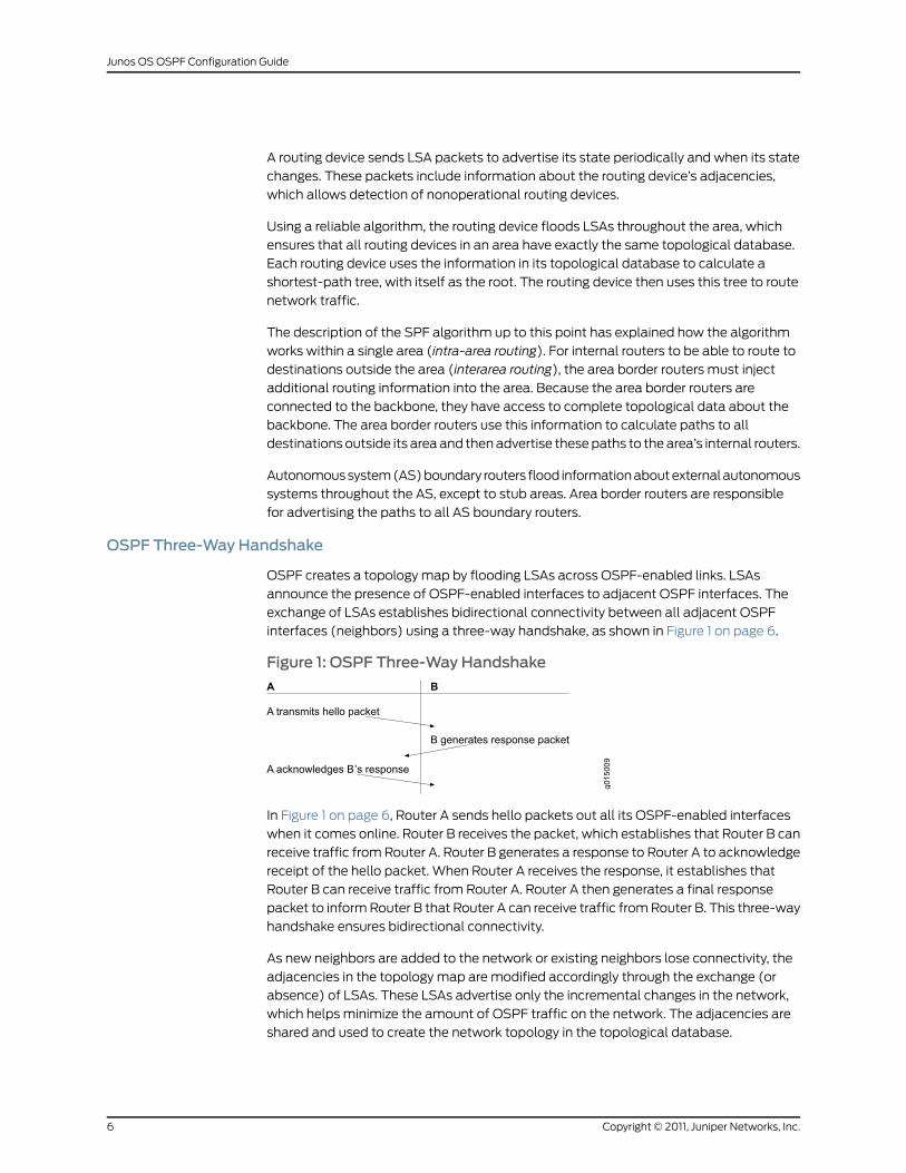
OSPF creates a topology map by flooding LSAs across OSPF-enabled links. LSAs
announce the presence of OSPF-enabled interfaces to adjacent OSPF interfaces. The
exchange of LSAs establishes bidirectional connectivity between all adjacent OSPF
interfaces (neighbors) using a three-way handshake, as shown in Figure 1 on page 6.
Figure 1: OSPF Three-Way Handshake
In Figure 1 on page 6, Router A sends hello packets out all its OSPF-enabled interfaces
when it comes online. Router B receives the packet, which establishes that Router B can
receive traffic from Router A. Router B generates a response to Router A to acknowledge
receipt of the hello packet. When Router A receives the response, it establishes that
Router B can receive traffic from Router A. Router A then generates a final response
packet to inform Router B that Router A can receive traffic from Router B. This three-way
handshake ensures bidirectional connectivity.
As new neighbors are added to the network or existing neighbors lose connectivity, the
adjacencies in the topology map are modified accordingly through the exchange (or
absence) of LSAs. These LSAs advertise only the incremental changes in the network,
which helps minimize the amount of OSPF traffic on the network. The adjacencies are
shared and used to create the network topology in the topological database.
Copyright © 2011, Juniper Networks, Inc.6
Junos OS OSPF Configuration Guide
OSPF Version 3
OSPFv3 is a modified version of OSPF that supports IP version 6 (IPv6) addressing.
OSPFv3 differs from OSPFv2 in the following ways:
• All neighbor ID information is based on a 32-bit router ID.
• The protocol runs per link rather than per subnet.
• Router and network link-state advertisements (LSAs) do not carry prefix information.
• Two new LSA types are included: link-LSA and intra-area-prefix-LSA.
• Flooding scopes are as follows:
• Link-local
• Area
• AS
• Link-local addresses are used for all neighbor exchanges except virtual links.
• Authentication is removed. The IPv6 authentication header relies on the IP layer.
• The packet format has changed as follows:
• Version number 2 is now version number 3.
• The db option field has been expanded to 24 bits.
• Authentication information has been removed.
• Hello messages do not have address information.
• Two new option bits are included: R and V6.
• Type 3 summary LSAs have been renamed inter-area-prefix-LSAs.
• Type 4 summary LSAs have been renamed inter-area-router-LSAs.
RelatedDocumentation
Understanding OSPF Areas and Backbone Areas•
• OSPF Configuration Overview
• Junos OS OSPF Version 3 for IPv6 Feature Guide
7Copyright © 2011, Juniper Networks, Inc.
Introduction to OSPF
OSPF Areas and Router Functionality Overview
In OSPF, a single autonomous system (AS) can be divided into smaller groups called
areas. This reduces the number of link-state advertisements (LSAs) and other OSPF
overhead traffic sent on the network, and it reduces the size of the topology database
that each router must maintain. The routing devices that participate in OSPF routing
perform one or more functions based on their location in the network.
This topic describes the following OSPF area types and routing device functions:
• Areas on page 8
• Area Border Routers on page 8
• Backbone Areas on page 8
• AS Boundary Routers on page 9
• Backbone Router on page 9
• Internal Router on page 9
• Stub Areas on page 9
• Not-So-Stubby Areas on page 10
• Transit Areas on page 10
Areas
An area is a set of networks and hosts within an AS that have been administratively
grouped together. We recommend that you configure an area as a collection of contiguous
IP subnetted networks. Routing devices that are wholly within an area are called internal
routers. All interfaces on internal routers are directly connected to networks within the
area.
The topology of an area is hidden from the rest of the AS, thus significantly reducing
routing traffic in the AS. Also, routing within the area is determined only by the area’s
topology, providing the area with some protection from bad routing data.
All routing devices within an area have identical topology databases.
Area Border Routers
Routing devices that belong to more than one area and connect one or more OSPF areas
to the backbone area are calledareaborder routers (ABRs). At least one interface is within
the backbone while another interface is in another area. ABRs also maintain a separate
topological database for each area to which they are connected.
Backbone Areas
An OSPF backbone area consists of all networks in area ID 0.0.0.0, their attached routing
devices, and all ABRs. The backbone itself does not have any ABRs. The backbone
distributes routing information between areas. The backbone is simply another area, so
the terminology and rules of areas apply: a routing device that is directly connected to
Copyright © 2011, Juniper Networks, Inc.8
Junos OS OSPF Configuration Guide
the backbone is an internal router on the backbone, and the backbone’s topology is
hidden from the other areas in the AS.
The routing devices that make up the backbone must be physically contiguous. If they
are not, you must configure virtual links to create the appearance of backbone connectivity.
You can create virtual links between any two ABRs that have an interface to a common
nonbackbone area. OSPF treats two routing devices joined by a virtual link as if they were
connected to an unnumbered point-to-point network.
AS Boundary Routers
Routing devices that exchange routing information with routing devices in non-OSPF
networks are called AS boundary routers. They advertise externally learned routes
throughout the OSPF AS. Depending on the location of the AS boundary router in the
network, it can be an ABR, a backbone router, or an internal router (with the exception
of stub areas). Internal routers within a stub area cannot be an AS boundary router
because stub areas cannot contain any Type 5 LSAs.
Routing devices within the area where the AS boundary router resides know the path to
that AS boundary router. Any routing device outside the area only knows the path to the
nearest ABR that is in the same area where the AS boundary router resides.
Backbone Router
Backbone routers are routing devices that have one or more interfaces connected to the
OSPF backbone area (area ID 0.0.0.0).
Internal Router
Routing devices that connect to only one OSPF area are called internal routers. All
interfaces on internal routers are directly connected to networks within a single area.
Stub Areas
Stub areas are areas through which or into which AS external advertisements are not
flooded. You might want to create stub areas when much of the topological database
consists of AS external advertisements. Doing so reduces the size of the topological
databases and therefore the amount of memory required on the internal routers in the
stub area.
Routing devices within a stub area rely on the default routes originated by the area’s ABR
to reach external AS destinations. You must configure the default-metric option on the
ABR before it advertises a default route. Once configured, the ABR advertises a default
route in place of the external routes that are not being advertised within the stub area,
so that routing devices in the stub area can reach destinations outside the area.
The following restrictions apply to stub areas: you cannot create a virtual link through a
stub area, a stub area cannot contain an AS boundary router, the backbone cannot be a
stub area, and you cannot configure an area as both a stub area and a not-so-stubby
area.
9Copyright © 2011, Juniper Networks, Inc.
Introduction to OSPF
Not-So-Stubby Areas
An OSPF stub area has no external routes in it, so you cannot redistribute from another
protocol into a stub area. A not-so-stubby area (NSSA) allows external routes to be
flooded within the area. These routes are then leaked into other areas. However, external
routes from other areas still do not enter the NSSA.
The following restriction applies to NSSAs: you cannot configure an area as both a stub
area and an NSSA.
Transit Areas
Transit areas are used to pass traffic from one adjacent area to the backbone (or to
another area if the backbone is more than two hops away from an area). The traffic does
not originate in, nor is it destined for, the transit area.
RelatedDocumentation
OSPF Overview on page 4•
• Packets Overview on page 10
• OSPF Configuration Overview
• Understanding OSPF Areas and Backbone Areas
• Understanding OSPF Stub Areas, Totally Stubby Areas, and Not-So-Stubby Areas
Packets Overview
There are several types of link-state advertisement (LSA) packets.
This topic describes the following information:
• OSPF Packet Header on page 10
• Hello Packets on page 11
• Database Description Packets on page 11
• Link-State Request Packets on page 11
• Link-State Update Packets on page 12
• Link-State Acknowledgment Packets on page 12
• Link-State Advertisement Packet Types on page 12
OSPF Packet Header
All OSPFv2 packets have a common 24-byte header, and OSPFv3 packets have a common
16-byte header, that contains all information necessary to determine whether OSPF
should accept the packet. The header consists of the following fields:
• Version number—The current OSPF version number. This can be either 2 or 3.
• Type—Type of OSPF packet.
• Packet length—Length of the packet, in bytes, including the header.
Copyright © 2011, Juniper Networks, Inc.10
Junos OS OSPF Configuration Guide
• Router ID—IP address of the router from which the packet originated.
• Area ID—Identifier of the area in which the packet is traveling. Each OSPF packet is
associated with a single area. Packets traveling over a virtual link are labeled with the
backbone area ID, 0.0.0.0. .
• Checksum—Fletcher checksum.
• Authentication—(OSPFv2 only) Authentication scheme and authentication information.
• Instance ID—(OSPFv3 only) Identifier used when there are multiple OSPFv3 realms
configured on a link.
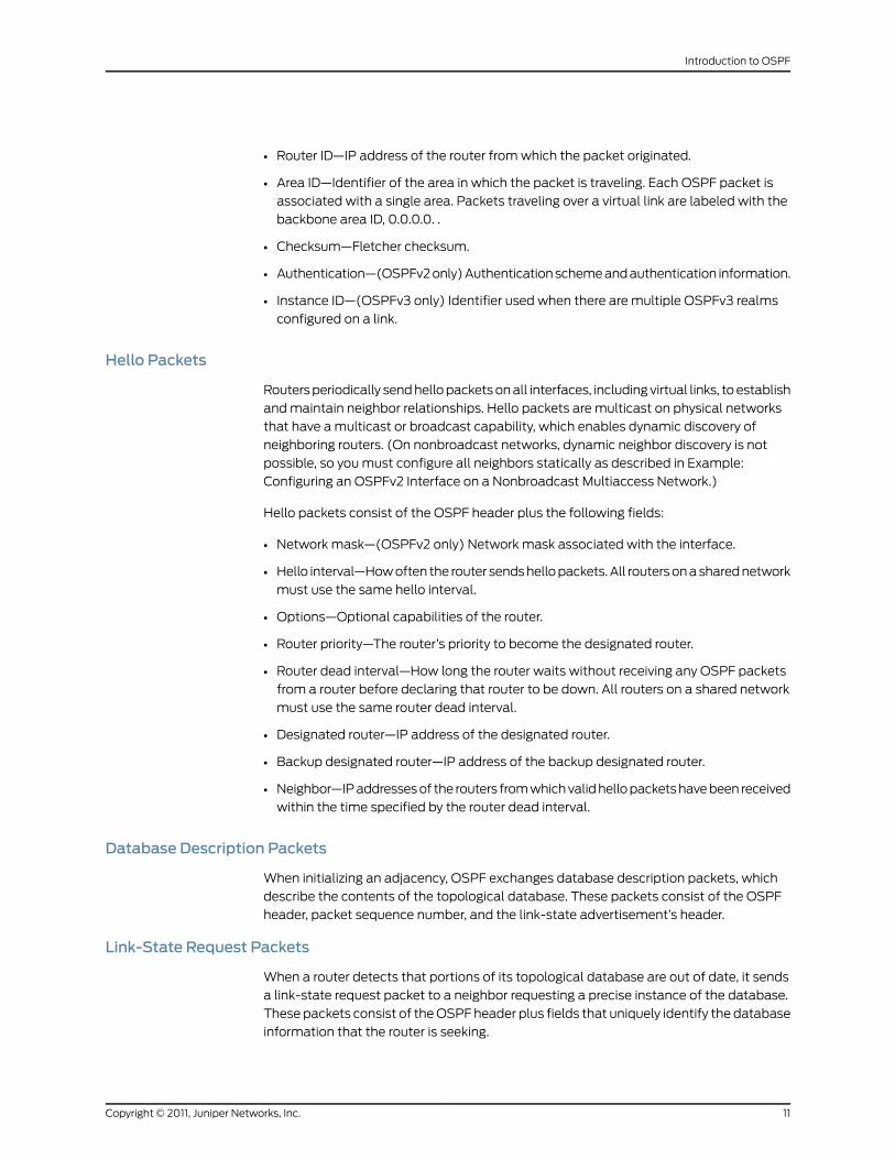
Hello Packets
Routers periodically send hello packets on all interfaces, including virtual links, to establish
and maintain neighbor relationships. Hello packets are multicast on physical networks
that have a multicast or broadcast capability, which enables dynamic discovery of
neighboring routers. (On nonbroadcast networks, dynamic neighbor discovery is not
possible, so you must configure all neighbors statically as described in Example:
Configuring an OSPFv2 Interface on a Nonbroadcast Multiaccess Network.)
Hello packets consist of the OSPF header plus the following fields:
• Network mask—(OSPFv2 only) Network mask associated with the interface.
• Hello interval—How often the router sends hello packets. All routers on a shared network
must use the same hello interval.
• Options—Optional capabilities of the router.
• Router priority—The router’s priority to become the designated router.
• Router dead interval—How long the router waits without receiving any OSPF packets
from a router before declaring that router to be down. All routers on a shared network
must use the same router dead interval.
• Designated router—IP address of the designated router.
• Backup designated router—IP address of the backup designated router.
• Neighbor—IP addresses of the routers from which valid hello packets have been received
within the time specified by the router dead interval.
Database Description Packets
When initializing an adjacency, OSPF exchanges database description packets, which
describe the contents of the topological database. These packets consist of the OSPF
header, packet sequence number, and the link-state advertisement’s header.
Link-State Request Packets
When a router detects that portions of its topological database are out of date, it sends
a link-state request packet to a neighbor requesting a precise instance of the database.
These packets consist of the OSPF header plus fields that uniquely identify the database
information that the router is seeking.
11Copyright © 2011, Juniper Networks, Inc.
Introduction to OSPF
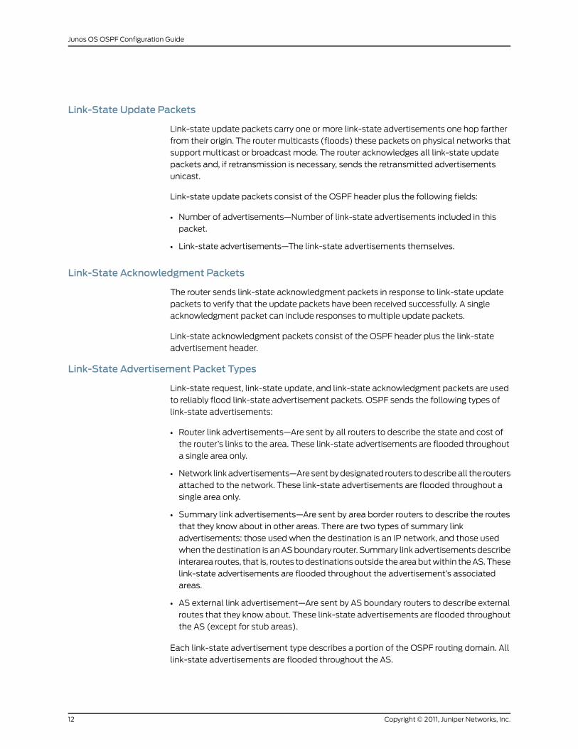
Link-State Update Packets
Link-state update packets carry one or more link-state advertisements one hop farther
from their origin. The router multicasts (floods) these packets on physical networks that
support multicast or broadcast mode. The router acknowledges all link-state update
packets and, if retransmission is necessary, sends the retransmitted advertisements
unicast.
Link-state update packets consist of the OSPF header plus the following fields:
• Number of advertisements—Number of link-state advertisements included in this
packet.
• Link-state advertisements—The link-state advertisements themselves.
Link-State Acknowledgment Packets
The router sends link-state acknowledgment packets in response to link-state update
packets to verify that the update packets have been received successfully. A single
acknowledgment packet can include responses to multiple update packets.
Link-state acknowledgment packets consist of the OSPF header plus the link-state
advertisement header.
Link-State Advertisement Packet Types
Link-state request, link-state update, and link-state acknowledgment packets are used
to reliably flood link-state advertisement packets. OSPF sends the following types of
link-state advertisements:
• Router link advertisements—Are sent by all routers to describe the state and cost of
the router’s links to the area. These link-state advertisements are flooded throughout
a single area only.
• Network link advertisements—Are sent by designated routers to describe all the routers
attached to the network. These link-state advertisements are flooded throughout a
single area only.
• Summary link advertisements—Are sent by area border routers to describe the routes
that they know about in other areas. There are two types of summary link
advertisements: those used when the destination is an IP network, and those used
when the destination is an AS boundary router. Summary link advertisements describe
interarea routes, that is, routes to destinations outside the area but within the AS. These
link-state advertisements are flooded throughout the advertisement’s associated
areas.
• AS external link advertisement—Are sent by AS boundary routers to describe external
routes that they know about. These link-state advertisements are flooded throughout
the AS (except for stub areas).
Each link-state advertisement type describes a portion of the OSPF routing domain. All
link-state advertisements are flooded throughout the AS.
Copyright © 2011, Juniper Networks, Inc.12
Junos OS OSPF Configuration Guide
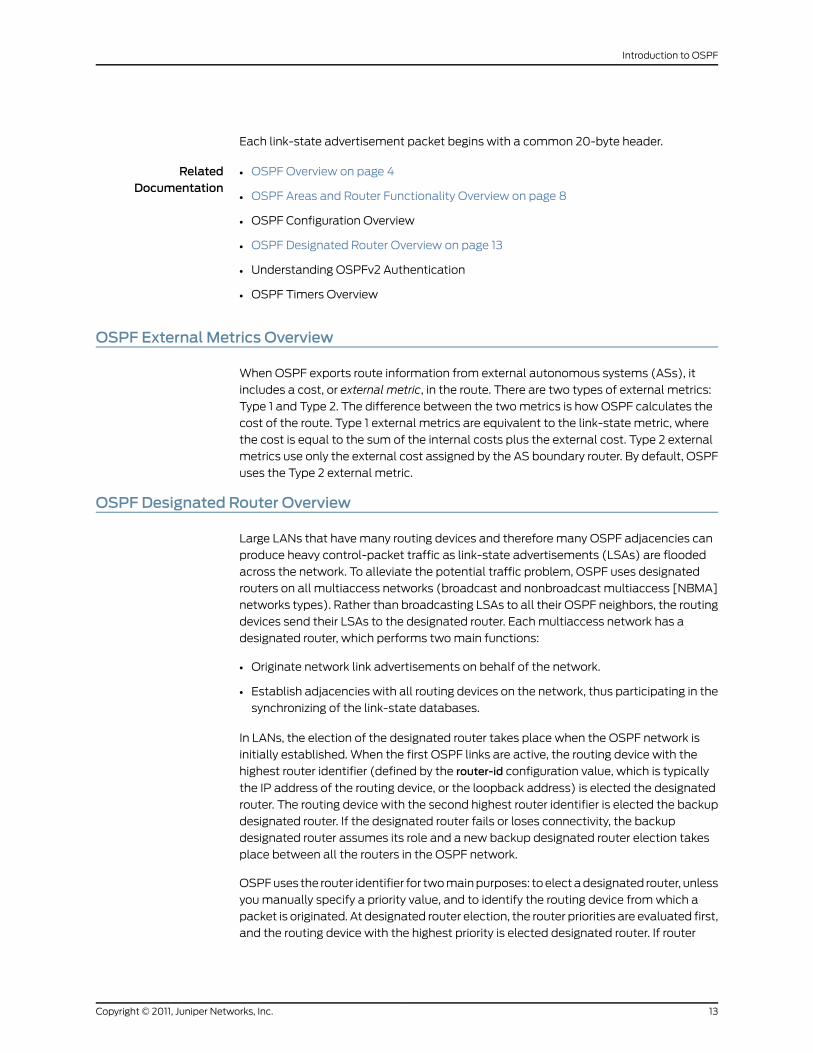
Each link-state advertisement packet begins with a common 20-byte header.
RelatedDocumentation
OSPF Overview on page 4•
• OSPF Areas and Router Functionality Overview on page 8
• OSPF Configuration Overview
• OSPF Designated Router Overview on page 13
• Understanding OSPFv2 Authentication
• OSPF Timers Overview
OSPF External Metrics Overview
When OSPF exports route information from external autonomous systems (ASs), it
includes a cost, or external metric, in the route. There are two types of external metrics:
Type 1 and Type 2. The difference between the two metrics is how OSPF calculates the
cost of the route. Type 1 external metrics are equivalent to the link-state metric, where
the cost is equal to the sum of the internal costs plus the external cost. Type 2 external
metrics use only the external cost assigned by the AS boundary router. By default, OSPF
uses the Type 2 external metric.
OSPF Designated Router Overview
Large LANs that have many routing devices and therefore many OSPF adjacencies can
produce heavy control-packet traffic as link-state advertisements (LSAs) are flooded
across the network. To alleviate the potential traffic problem, OSPF uses designated
routers on all multiaccess networks (broadcast and nonbroadcast multiaccess [NBMA]
networks types). Rather than broadcasting LSAs to all their OSPF neighbors, the routing
devices send their LSAs to the designated router. Each multiaccess network has a
designated router, which performs two main functions:
• Originate network link advertisements on behalf of the network.
• Establish adjacencies with all routing devices on the network, thus participating in the
synchronizing of the link-state databases.
In LANs, the election of the designated router takes place when the OSPF network is
initially established. When the first OSPF links are active, the routing device with the
highest router identifier (defined by the router-id configuration value, which is typically
the IP address of the routing device, or the loopback address) is elected the designated
router. The routing device with the second highest router identifier is elected the backup
designated router. If the designated router fails or loses connectivity, the backup
designated router assumes its role and a new backup designated router election takes
place between all the routers in the OSPF network.
OSPF uses the router identifier for two main purposes: to elect a designated router, unless
you manually specify a priority value, and to identify the routing device from which a
packet is originated. At designated router election, the router priorities are evaluated first,
and the routing device with the highest priority is elected designated router. If router
13Copyright © 2011, Juniper Networks, Inc.
Introduction to OSPF
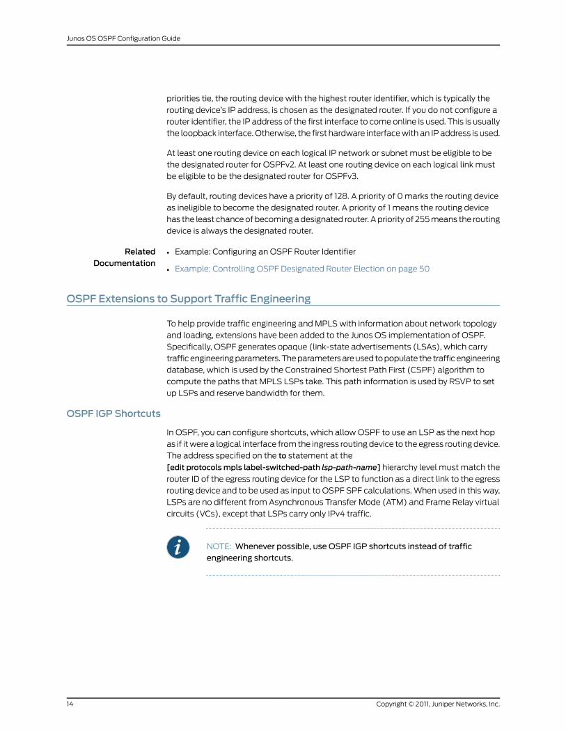
priorities tie, the routing device with the highest router identifier, which is typically the
routing device’s IP address, is chosen as the designated router. If you do not configure a
router identifier, the IP address of the first interface to come online is used. This is usually
the loopback interface. Otherwise, the first hardware interface with an IP address is used.
At least one routing device on each logical IP network or subnet must be eligible to be
the designated router for OSPFv2. At least one routing device on each logical link must
be eligible to be the designated router for OSPFv3.
By default, routing devices have a priority of 128. A priority of 0 marks the routing device
as ineligible to become the designated router. A priority of 1 means the routing device
has the least chance of becoming a designated router. A priority of 255 means the routing
device is always the designated router.
RelatedDocumentation
Example: Configuring an OSPF Router Identifier•
• Example: Controlling OSPF Designated Router Election on page 50
OSPF Extensions to Support Traffic Engineering
To help provide traffic engineering and MPLS with information about network topology
and loading, extensions have been added to the Junos OS implementation of OSPF.
Specifically, OSPF generates opaque (link-state advertisements (LSAs), which carry
traffic engineering parameters. The parameters are used to populate the traffic engineering
database, which is used by the Constrained Shortest Path First (CSPF) algorithm to
compute the paths that MPLS LSPs take. This path information is used by RSVP to set
up LSPs and reserve bandwidth for them.
OSPF IGP Shortcuts
In OSPF, you can configure shortcuts, which allow OSPF to use an LSP as the next hop
as if it were a logical interface from the ingress routing device to the egress routing device.
The address specified on the to statement at the
[edit protocolsmpls label-switched-path lsp-path-name] hierarchy level must match the
router ID of the egress routing device for the LSP to function as a direct link to the egress
routing device and to be used as input to OSPF SPF calculations. When used in this way,
LSPs are no different from Asynchronous Transfer Mode (ATM) and Frame Relay virtual
circuits (VCs), except that LSPs carry only IPv4 traffic.
NOTE: Whenever possible, use OSPF IGP shortcuts instead of trafficengineering shortcuts.
Copyright © 2011, Juniper Networks, Inc.14
Junos OS OSPF Configuration Guide
OSPF Database Protection Overview
OSPF database protection allows you to limit the number of link-state advertisements
(LSAs) not generated by the local router in a given OSPF routing instance, helping to
protect the link-state database from being flooded with excessive LSAs. This feature is
particularly useful if VPN routing and forwarding is configured on your provider edge and
customer edge routers using OSPF as the routing protocol. An overrun link-state database
on the customer edge router can exhaust resources on the provider edge router and
impact the rest of the service provider network.
When you enable OSPF database protection, the maximum number of LSAs you specify
includes all LSAs whose advertising router ID is not equal to the local router ID
(nonself-generated LSAs). These might include external LSAs as well as LSAs with any
scope such as the link, area, and autonomous system (AS).
Once the specified maximum LSA count is exceeded, the database typically enters into
the ignore state. In this state, all neighbors are brought down, and nonself-generated
LSAs are destroyed. In addition, the database sends out hellos but ignores all received
packets. As a result, the database does not form any full neighbors, and therefore does
not learn about new LSAs. However, if you have configured the warning-only option, only
a warning is issued and the database does not enter the ignore state but continues to
operate as before.
You can also configure one or more of the following options:
• A warning threshold for issuing a warning message before the LSA limit is reached.
• An ignore state time during which the database must remain in the ignore state and
after which normal operations can be resumed.
• An ignore state count that limits the number of times the database can enter the ignore
state, after which it must enter the isolate state. The isolate state is very similar to the
ignore state, but has one important difference: once the database enters the isolate
state, it must remain there until you issue a command to clear database protection
before it can return to normal operations.
• A reset time during which the database must stay out of the ignore or isolate state
before it is returned to a normal operating state.
RelatedDocumentation
• Configuring OSPF Database Protection on page 135
• database-protection on page 150
15Copyright © 2011, Juniper Networks, Inc.
Introduction to OSPF

Copyright © 2011, Juniper Networks, Inc.16
Junos OS OSPF Configuration Guide
CHAPTER 2
Introduction to OSPF ConfigurationGuidelines
• BFD Authentication for OSPF Overview on page 17
• Loop-Free Alternate Routes for OSPF Overview on page 19
BFD Authentication for OSPFOverview
BFD enables rapid detection of communication failures between adjacent systems. By
default, authentication for BFD sessions is disabled. However, when you run BFD over
Network Layer protocols, the risk of service attacks can be significant. We strongly
recommend using authentication if you are running BFD over multiple hops or through
insecure tunnels. Beginning with Junos OS Release 9.6, the Junos OS supports
authentication for BFD sessions running over OSPFv2. BFD authentication is not supported
on MPLS OAM sessions. BFD authentication is only supported in the domestic image and
is not available in the export image.
You authenticate BFD sessions by specifying an authentication algorithm and keychain,
and then associating that configuration information with a security authentication
keychain using the keychain name.
The following sections describe the supported authentication algorithms, security
keychains, and level of authentication that can be configured:
• BFD Authentication Algorithms on page 17
• Security Authentication Keychains on page 18
• Strict Versus Loose Authentication on page 18
BFD Authentication Algorithms
Junos OS supports the following algorithms for BFD authentication:
• simple-password—Plain-text password. One to 16 bytes of plain text are used to
authenticate the BFD session. One or more passwords can be configured. This method
is the least secure and should be used only when BFD sessions are not subject to packet
interception.
• keyed-md5—Keyed Message Digest 5 hash algorithm for sessions with transmit and
receive intervals greater than 100 ms. To authenticate the BFD session, keyed MD5
17Copyright © 2011, Juniper Networks, Inc.
uses one or more secret keys (generated by the algorithm) and a sequence number
that is updated periodically. With this method, packets are accepted at the receiving
end of the session if one of the keys matches and the sequence number is greater than
or equal to the last sequence number received. Although more secure than a simple
password, this method is vulnerable to replay attacks. Increasing the rate at which the
sequence number is updated can reduce this risk.
• meticulous-keyed-md5—Meticulous keyed Message Digest 5 hash algorithm. This
method works in the same manner as keyed MD5, but the sequence number is updated
with every packet. Although more secure than keyed MD5 and simple passwords, this
method might take additional time to authenticate the session.
• keyed-sha-1—Keyed Secure Hash Algorithm I for sessions with transmit and receive
intervals greater than 100 ms. To authenticate the BFD session, keyed SHA uses one
or more secret keys (generated by the algorithm) and a sequence number that is
updated periodically. The key is not carried within the packets. With this method,
packets are accepted at the receiving end of the session if one of the keys matches
and the sequence number is greater than the last sequence number received.
• meticulous-keyed-sha-1—Meticulous keyed Secure Hash Algorithm I. This method
works in the same manner as keyed SHA, but the sequence number is updated with
every packet. Although more secure than keyed SHA and simple passwords, this method
might take additional time to authenticate the session.
NOTE: Nonstop active routing (NSR) is not supported withmeticulous-keyed-md5 andmeticulous-keyed-sha-1 authenticationalgorithms. BFD sessions using these algorithmsmight go down after aswitchover.
Security Authentication Keychains
The security authentication keychain defines the authentication attributes used for
authentication key updates. When the security authentication keychain is configured and
associated with a protocol through the keychain name, authentication key updates can
occur without interrupting routing and signaling protocols.
The authentication keychain contains one or more keychains. Each keychain contains
one or more keys. Each key holds the secret data and the time at which the key becomes
valid. The algorithm and keychain must be configured on both ends of the BFD session,
and they must match. Any mismatch in configuration prevents the BFD session from
being created.
BFD allows multiple clients per session, and each client can have its own keychain and
algorithm defined. To avoid confusion, we recommend specifying only one security
authentication keychain.
Strict Versus Loose Authentication
By default, strict authentication is enabled and authentication is checked at both ends
of each BFD session. Optionally, to smooth migration from nonauthenticated sessions
Copyright © 2011, Juniper Networks, Inc.18
Junos OS OSPF Configuration Guide
to authenticated sessions, you can configure loose checking. When loose checking is
configured, packets are accepted without authentication being checked at each end of
the session. This feature is intended for transitional periods only.
RelatedDocumentation
Configuring BFD Authentication for OSPF on page 76
Example: Configuring BFD for OSPF on page 72
•
• bfd-liveness-detection on page 146
• authentication-key-chains statement in the Junos OS System Basics Configuration Guide
• show bfd session command in the Junos OS Routing Protocols and Policies Command
Reference
Loop-Free Alternate Routes for OSPFOverview
Support for OSPF loop-free alternate routes essentially adds IP fast-reroute capability
for OSPF. Junos OS precomputes loop-free backup routes for all OSPF routes. These
backup routes are preinstalled in the Packet Forwarding Engine, which performs a local
repair and implements the backup path when the link for a primary next hop for a particular
route is no longer available. With local repair, the Packet Forwarding Engine can correct
a path failure before it receives precomputed paths from the Routing Engine. Local repair
reduces the amount of time needed to reroute traffic to less than 50 milliseconds. In
contrast, global repair can take up to 800 milliseconds to compute a new route. Local
repair enables traffic to continue to be routed using a backup path until global repair is
able to calculate a new route.
A loop-free path is one that does not forward traffic back through the routing device to
reach a given destination. That is, a neighbor whose shortest path first to the destination
traverses the routing device that is not used as a backup route to that destination. To
determine loop-free alternate paths for OSPF routes, Junos OS runs shortest-path-first
(SPF) calculations on each one-hop neighbor. You can enable support for alternate
loop-free routes on any OSPF interface. Because it is common practice to enable LDP
on an interface for which OSPF is already enabled, this feature also provides support for
LDP label-switched paths (LSPs.)
NOTE: If you enable support for alternate loop-free routes on an interfaceconfigured for both LDP and OSPF, you can use the traceroute command to
trace the active path to the primary next hop.
The level of backup coverage available through OSPF routes depends on the actual
network topology and is typically less than 100 percent for all destinations on any given
routing device. You can extend backup coverage to include RSVP LSP paths.
19Copyright © 2011, Juniper Networks, Inc.
Introduction to OSPF Configuration Guidelines
Junos OS provides two mechanisms for route redundancy for OSPF through alternate
loop-free routes:
• Link protection—Offers per-link traffic protection. Use link protection when you assume
that only a single link might become unavailable but that the neighboring node on the
primary path would still be available through another interface.
• Node-link protection—Establishes an alternate path through a different routing device
altogether. Use node-link protection when you assume that access to a node is lost
when a link is no longer available. As a result, Junos OS calculates a backup path that
avoids the primary next-hop routing device.
When you enable link protection or node-link protection on an OSPF interface, Junos OS
creates an alternate path to the primary next hop for all destination routes that traverse
a protected interface.
RelatedDocumentation
• Configuring Link Protection for OSPF on page 124
• Configuring Node-Link Protection for OSPF on page 125
• Excluding an OSPF Interface as a Backup for a Protected Interface on page 126
• Configuring Backup SPF Options for Protected OSPF Interfaces on page 127
• Configuring RSVP Label-Switched Paths as Backup Paths for OSPF on page 129
Copyright © 2011, Juniper Networks, Inc.20
Junos OS OSPF Configuration Guide
PART 2
Configuration
• OSPF Configuration Guidelines on page 23
21Copyright © 2011, Juniper Networks, Inc.

Copyright © 2011, Juniper Networks, Inc.22
Junos OS OSPF Configuration Guide
CHAPTER 3
OSPF Configuration Guidelines
• Configuring OSPF on page 24
• Minimum OSPF Configuration on page 29
• Configuring OSPF Areas on page 29
• Disabling Export of LSAs into NSSAs Attached to ASBR ABRs on page 33
• Example: Disabling OSPFv2 Compatibility with RFC 1583 on page 33
• Configuring OSPF on Interfaces on page 34
• Example: Configuring Multiarea Adjacency for OSPF on page 37
• Example: Configuring Multiple Address Families for OSPFv3 on page 41
• Configuring Authentication for OSPFv2 on page 44
• Configuring Authentication for OSPFv3 on page 48
• Example: Limiting the Number of Prefixes Exported to OSPF on page 48
• Example: Controlling OSPF Designated Router Election on page 50
• Example: Summarizing Ranges of Routes in OSPF Link-State Advertisements on page 52
• Example: Controlling the Cost of Individual OSPF Network Segments on page 57
• Example: Dynamically Adjusting OSPF Interface Metrics Based on Bandwidth on page 61
• Example: Controlling OSPF Route Preferences on page 63
• Example: Configuring OSPF Timers on page 66
• Configuring OSPF Refresh and Flooding Reduction in Stable Topologies on page 71
• Example: Configuring BFD for OSPF on page 72
• Configuring BFD Authentication for OSPF on page 76
• Example: Configuring Synchronization Between LDP and IGPs on page 79
• Example: Configuring Graceful Restart for OSPF on page 82
• Example: Configuring SPF Algorithm Options for OSPF on page 86
• Example: Configuring a Passive OSPF Interface on page 89
• Example: Configuring OSPF Passive Traffic Engineering Mode on page 91
• Example: Advertising Label-Switched Paths into OSPFv2 on page 93
• Example: Configuring OSPF to Make Routing Devices Appear Overloaded on page 104
• Example: Enabling OSPF Traffic Engineering Support on page 107
23Copyright © 2011, Juniper Networks, Inc.
• Example: Configuring the Traffic Engineering Metric for a Specific OSPF
Interface on page 112
• Applying Policies to OSPF Routes on page 114
• Configuring OSPF Routing Table Groups on page 117
• Example: Configuring OSPFv2 Sham Links on page 117
• Example: Configuring OSPFv2 Peer interfaces on page 123
• Configuring Link Protection for OSPF on page 124
• Configuring Node-Link Protection for OSPF on page 125
• Excluding an OSPF Interface as a Backup for a Protected Interface on page 126
• Configuring Backup SPF Options for Protected OSPF Interfaces on page 127
• Configuring RSVP Label-Switched Paths as Backup Paths for OSPF on page 129
• Example: Tracing OSPF Protocol Traffic on page 130
• Configuring OSPF Database Protection on page 135
Configuring OSPF
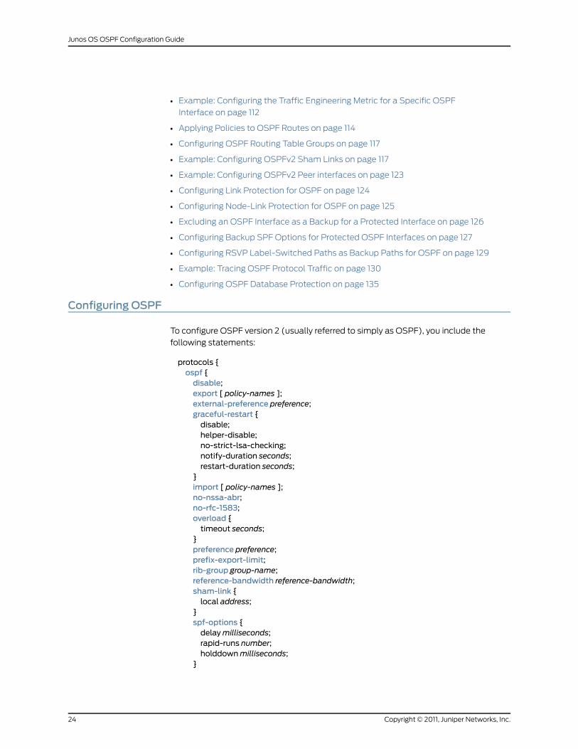
To configure OSPF version 2 (usually referred to simply as OSPF), you include the
following statements:
protocols {ospf {disable;export [ policy-names ];external-preference preference;graceful-restart {disable;helper-disable;no-strict-lsa-checking;notify-duration seconds;restart-duration seconds;
}import [ policy-names ];no-nssa-abr;no-rfc-1583;overload {timeout seconds;
}preference preference;prefix-export-limit;rib-group group-name;reference-bandwidth reference-bandwidth;sham-link {local address;
}spf-options {delaymilliseconds;rapid-runs number;holddownmilliseconds;
}
Copyright © 2011, Juniper Networks, Inc.24
Junos OS OSPF Configuration Guide
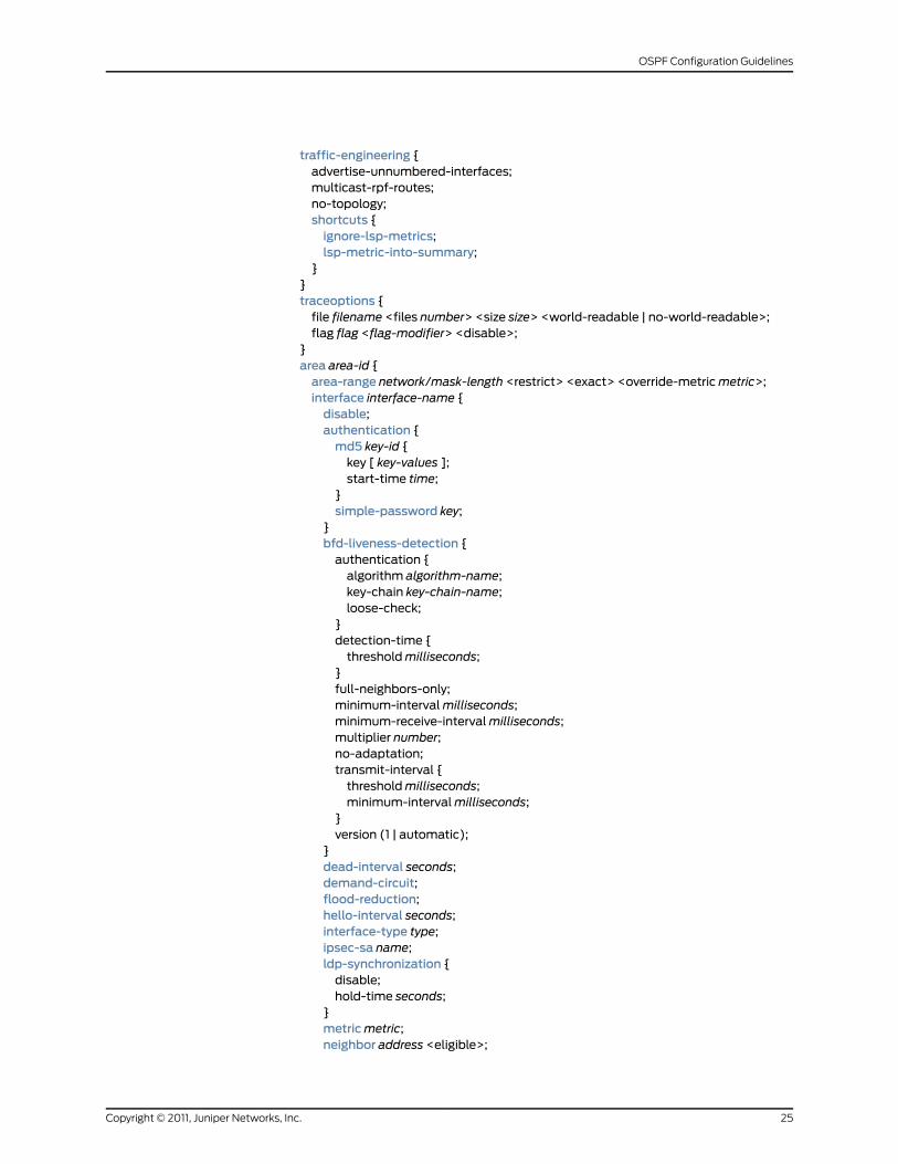
traffic-engineering {advertise-unnumbered-interfaces;multicast-rpf-routes;no-topology;shortcuts {ignore-lsp-metrics;lsp-metric-into-summary;
}}traceoptions {file filename <files number> <size size> <world-readable | no-world-readable>;flag flag <flag-modifier> <disable>;
}area area-id {area-range network/mask-length <restrict> <exact> <override-metricmetric>;interface interface-name {disable;authentication {md5 key-id {key [ key-values ];start-time time;
}simple-password key;
}bfd-liveness-detection {authentication {algorithm algorithm-name;key-chain key-chain-name;loose-check;
}detection-time {thresholdmilliseconds;
}full-neighbors-only;minimum-intervalmilliseconds;minimum-receive-intervalmilliseconds;multiplier number;no-adaptation;transmit-interval {thresholdmilliseconds;minimum-intervalmilliseconds;
}version (1 | automatic);
}dead-interval seconds;demand-circuit;flood-reduction;hello-interval seconds;interface-type type;ipsec-sa name;ldp-synchronization {disable;hold-time seconds;
}metricmetric;neighbor address <eligible>;
25Copyright © 2011, Juniper Networks, Inc.
OSPF Configuration Guidelines
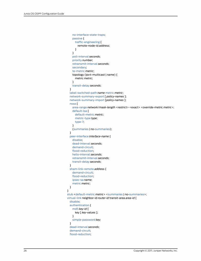
no-interface-state-traps;passive {traffic-engineering {remote-node-id address;
}}poll-interval seconds;priority number;retransmit-interval seconds;secondary;te-metricmetric;topology (ipv4-multicast | name) {metricmetric;
}transit-delay seconds;
}label-switched-path namemetricmetric;network-summary-export [ policy-names ];network-summary-import [policy-names ];nssa {area-range network/mask-length <restrict> <exact> <override-metricmetric>;default-lsa {default-metricmetric;metric-type type;type-7;
}(summaries | no-summaries);
}peer-interface interface-name {disable;dead-interval seconds;demand-circuit;flood-reduction;hello-interval seconds;retransmit-interval seconds;transit-delay seconds;
}sham-link-remote address {demand-circuit;flood-reduction;ipsec-sa name;metricmetric;
}}stub <default-metricmetric> <summaries | no-summaries>;virtual-link neighbor-id router-id transit-area area-id {disable;authentication {md5 key-id {key [ key-values ];
}simple-password key;
}dead-interval seconds;demand-circuit;flood-reduction;
Copyright © 2011, Juniper Networks, Inc.26
Junos OS OSPF Configuration Guide
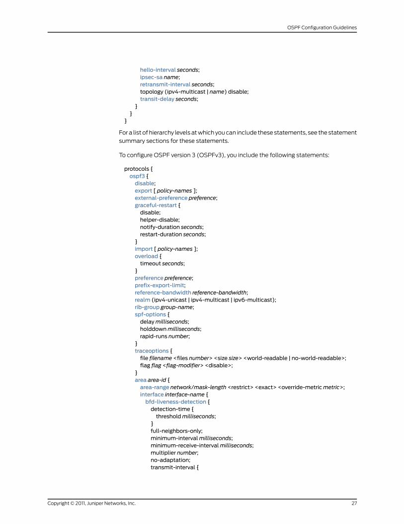
hello-interval seconds;ipsec-sa name;retransmit-interval seconds;topology (ipv4-multicast | name) disable;transit-delay seconds;
}}
}
For a list of hierarchy levels at which you can include these statements, see the statement
summary sections for these statements.
To configure OSPF version 3 (OSPFv3), you include the following statements:
protocols {ospf3 {disable;export [ policy-names ];external-preference preference;graceful-restart {disable;helper-disable;notify-duration seconds;restart-duration seconds;
}import [ policy-names ];overload {timeout seconds;
}preference preference;prefix-export-limit;reference-bandwidth reference-bandwidth;realm (ipv4-unicast | ipv4-multicast | ipv6-multicast);rib-group group-name;spf-options {delaymilliseconds;holddownmilliseconds;rapid-runs number;
}traceoptions {file filename <files number> <size size> <world-readable | no-world-readable>;flag flag <flag-modifier> <disable>;
}area area-id {area-range network/mask-length <restrict> <exact> <override-metricmetric>;interface interface-name {bfd-liveness-detection {detection-time {thresholdmilliseconds;
}full-neighbors-only;minimum-intervalmilliseconds;minimum-receive-intervalmilliseconds;multiplier number;no-adaptation;transmit-interval {
27Copyright © 2011, Juniper Networks, Inc.
OSPF Configuration Guidelines
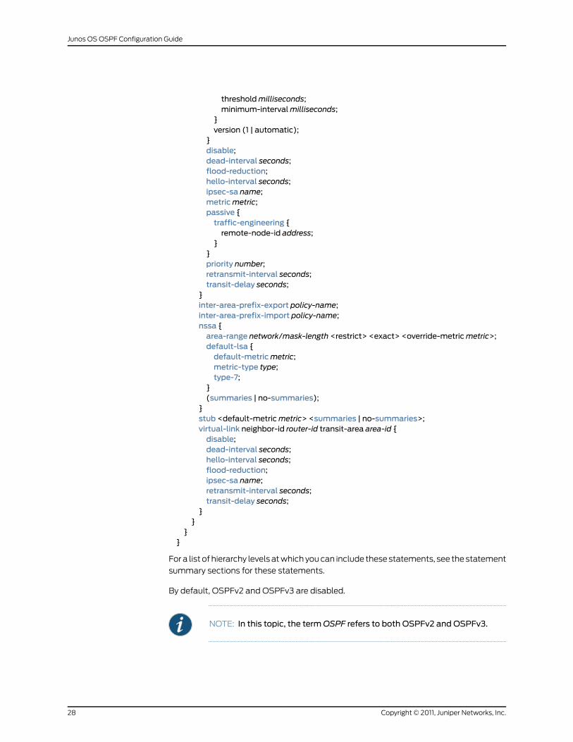
thresholdmilliseconds;minimum-intervalmilliseconds;
}version (1 | automatic);
}disable;dead-interval seconds;flood-reduction;hello-interval seconds;ipsec-sa name;metricmetric;passive {traffic-engineering {remote-node-id address;
}}priority number;retransmit-interval seconds;transit-delay seconds;
}inter-area-prefix-export policy-name;inter-area-prefix-import policy-name;nssa {area-range network/mask-length <restrict> <exact> <override-metricmetric>;default-lsa {default-metricmetric;metric-type type;type-7;
}(summaries | no-summaries);
}stub <default-metricmetric> <summaries | no-summaries>;virtual-link neighbor-id router-id transit-area area-id {disable;dead-interval seconds;hello-interval seconds;flood-reduction;ipsec-sa name;retransmit-interval seconds;transit-delay seconds;
}}
}}
For a list of hierarchy levels at which you can include these statements, see the statement
summary sections for these statements.
By default, OSPFv2 and OSPFv3 are disabled.
NOTE: In this topic, the termOSPF refers to both OSPFv2 and OSPFv3.
Copyright © 2011, Juniper Networks, Inc.28
Junos OS OSPF Configuration Guide
RelatedDocumentation
Junos OS OSPF Version 3 for IPv6 Feature Guide•
MinimumOSPF Configuration
You must create a backbone area if your network consists of multiple areas. An area
border router (ABR) must have at least one interface in the backbone area, or it must
have a virtual link to a routing device in the backbone area. To do this, include at least
the following statements. All other OSPF configuration statements are optional.
protocols {(ospf | ospf3 ) {area 0 {interface interface-name;
}}
}
For a list of hierarchy levels at which you can include these statements, see the statement
summary sections for these statements.
NOTE: When you configure OSPFv2 on an interface, youmust also includethe family inet statement at the [edit interfaces interface-name unit
logical-unit-number] hierarchy level. When you configure OSPFv3 on an
interface, youmust also include the family inet6 statement at the [edit
interfaces interface-name unit logical-unit-number] hierarchy level.
Configuring OSPF Areas
You can group the routing devices in a single autonomous system (AS) into areas to
reduce the amount of link-state advertisement (LSA) traffic on the network and to reduce
the size of the topological databases that OSPF routing devices must maintain. If you
do this, the AS must contain a single backbone area and optionally can contain any
number of nonbackbone areas. The routing devices that make up the backbone must be
physically contiguous. If they are not, you must configure virtual links to create the
appearance of connectivity. You also can configure stub areas, which are areas through
which AS external advertisements are not flooded, and not-so-stubby areas (NSSAs),
which allow external routes to be flooded within an area.
Junos OS supports active backbone detection. Active backbone detection is implemented
to verify that area border routers are connected to the backbone. If the connection to the
backbone area is lost, then the routing device’s default metric is not advertised, effectively
rerouting traffic through another area border router with a valid connection to the
backbone.
Active backbone detection enables transit through an area border router (ABR) with no
active backbone connection. An ABR advertises to other routing devices that it is an ABR
even if the connection to the backbone is down, so that the neighbors can consider it for
interarea routes.
29Copyright © 2011, Juniper Networks, Inc.
OSPF Configuration Guidelines
To configure areas, you can perform the following tasks:
• Configuring the OSPF Backbone Area on page 30
• Configuring OSPF Nonbackbone Areas on page 30
• Configuring OSPF Stub Areas on page 30
• Configuring OSPF Not-So-Stubby Areas on page 31
• Configuring OSPF Virtual Links on page 32
Configuring the OSPF Backbone Area
You must create a backbone area if your network consists of multiple areas. An ABR
must have at least one interface in the backbone area, or it must have a virtual link to a
routing device in the backbone area. The backbone comprises all ABRs and all routing
devices that are not included in any other area. You configure all these routing devices
by including the area 0.0.0.0 statement:
area 0.0.0.0;
For a list of hierarchy levels at which you can include this statement, see the statement
summary section for the statement.
Configuring OSPF Nonbackbone Areas
Each OSPF area consists of routing devices configured with the same area number. To
configure a routing device to be in an area, include the area statement. The area ID can
be any number except 0.0.0.0, which is reserved for the backbone area.
area area-id;
For a list of hierarchy levels at which you can include this statement, see the statement
summary section for the statement.
Configuring OSPF Stub Areas
Stub areas are areas into which OSPF does not flood AS external advertisements. You
might want to configure stub areas when much of the topological database consists of
AS external advertisements and you want to minimize the size of the topological
databases on an area’s routing devices.
You cannot configure an area as both a stub area and a not-so-stubby area (NSSA).
To configure a stub area, include the stub statement:
area area-id {stub <default-metricmetric> <summaries | no-summaries>;
}
For a list of hierarchy levels at which you can include this statement, see the statement
summary section for this statement.
To inject a default route with a specified metric value into the area, include the
default-metric option and a metric value. The default route matches any destination that
is not explicitly reachable from within the area.
Copyright © 2011, Juniper Networks, Inc.30
Junos OS OSPF Configuration Guide
To have the stub areas not advertise summary routes into the stub area, include the
no-summaries option. Only the default route is advertised, and only if you include the
default-metric option. The default route injected into the NSSA is a Type 3 LSA.
You must include the stub statement when configuring all routing devices that are in the
stub area.
NOTE: In Junos OS Release 8.5 and later, a router-identifier interface that isnot configured to runOSPF is no longer advertisedasa stubnetwork inOSPFlink-state advertisements. For more information about how to configure arouter identifier, see Configuring Router Identifiers for BGP and OSPF.
In JunosOSRelease 8.5 and later, OSPF advertises a local routewith a prefixlength of 32 as a stub link if the loopback interface is configuredwith a prefixlengthother than32.OSPFalsoadvertises thedirect routewith theconfiguredmask length, as in earlier releases.
Configuring OSPF Not-So-Stubby Areas
An OSPF stub area has no external routes, so you cannot redistribute from another
protocol into a stub area. An NSSA allows external routes to be flooded within the area.
These routes are then leaked into other areas. However, external routes from other areas
still do not enter the NSSA.
You cannot configure an area to be both a stub area and an NSSA.
To configure an NSSA, include the nssa statement:
area area-id {nssa {area-range network/mask-length <restrict> <exact> <override-metricmetric>;default-lsa {default-metricmetric;metric-type type;type-7;
}(summaries | no-summaries);
}}
For a list of hierarchy levels at which you can include this statement, see the statement
summary section for this statement.
By default, a default route is not advertised. To advertise a default route with the specified
metric within the area, include thedefault-metric statement. You can configure this option
only on ABRs.
To prevent an ABR from advertising summary routes into an NSSA, include the
no-summaries statement. If you include the default-metric option in addition to the
no-summaries statement, only the default route is advertised. The default route is a
Type 3 LSA injected into the NSSA. To flood summary LSAs into the NSSA area, include
31Copyright © 2011, Juniper Networks, Inc.
OSPF Configuration Guidelines
the summaries statement. When summaries is configured (which is the default if the
no-summaries statement is not specified), a Type 7 LSA is sent. To define the type of
metric, include the metric-type statement.
To aggregate external routes learned within the area when a route is advertised to other
areas, include one or more area-range statements. If you also include the restrict option,
the aggregate is not advertised, effectively creating a route filter. All external routes
learned within the area that do not fall into the range of one of the prefixes are advertised
individually to other areas. To restrict an exact area range, include the exact option. For
an example, you can suppress the exact 0/0 prefix from being advertised from a NSSA
area into the backbone area by including both the exact and restrict options. To override
the metric for the IP address range and configure a specific metric value, include the
override-metric option.
Configuring OSPF Virtual Links
If any routing device on the backbone is not physically connected to the backbone itself,
you must establish a virtual connection between that routing device and the backbone.
You can establish a virtual connection between ABRs by configuring an OSPF virtual link.
To configure an OSPF virtual link, include the virtual-link statement when configuring the
backbone area (area 0):
virtual-link neighbor-id router-id transit-area area-id;
To configure an OSPFv3 virtual link, include the virtual-link statement when configuring
the backbone area (area 0):
virtual-link neighbor-id router-id transit-area area-id;
For a list of hierarchy levels at which you can include this statement, see the statement
summary section for this statement.
Specify the router ID (as an IPv4 address) of the routing device at the other end of the
virtual link. This router must be an ABR that is physically connected to the backbone.
Also, specify the number of the area through which the virtual link transits.
For the virtual connection to work, you also must configure a link to the backbone area
on the remote ABR (the routing device at the other end of the LSP).
Example: Configuring an OSPF Virtual Link
Configure an OSPF virtual link on the local router. This routing device must be an area
border router that is physically connected to the backbone.
[edit protocols ospf]area 0.0.0.0 {virtual-link neighbor-id 192.168.0.3 transit-area 1.1.1.1;interface t3-1/0/0 {hello-interval 1;dead-interval 3;
}}
You must also configure an OSPF virtual link on the remote ABR:
Copyright © 2011, Juniper Networks, Inc.32
Junos OS OSPF Configuration Guide
[edit protocols ospf]area 0.0.0.0 {virtual-link neighbor-id 192.168.0.5 transit-area 1.1.1.1;
}
Disabling Export of LSAs into NSSAs Attached to ASBR ABRs
When an autonomous-system boundary router (ASBR) is also an ABR with an NSSA
area attached to it, a Type 7 LSA is exported into the NSSA area by default. If the ABR is
attached to multiple NSSA areas, a separate Type 7 LSA is exported into each NSSA
area by default.
NOTE: Type 7 LSAs are not exported into an NSSA if there is only one NSSAand backbone area connected to the ABR.
To disable exporting Type 7 LSAs into NSSAs, include the no-nssa-abr statement:
no-nssa-abr;
For a list of hierarchy levels at which you can include this statement, see the statement
summary section for this statement.
Example: Disabling OSPFv2 Compatibility with RFC 1583
This example shows how to disable OSPFv2 compatibility with RFC 1583 on the routing
device.
• Requirements on page 33
• Overview on page 33
• Configuration on page 34
• Verification on page 34
Requirements
No special configuration beyond device initialization is required before disabling OSPFv2
compatibility with RFC 1583.
Overview
The introduction of RFC 2328 changed the method used to calculate the routes in an
OSPF network. By default, the Junos OS implementation of OSPFv2 is compatible with
RFC 1583, so OSPF uses the minimum cost to determine the route to any of the networks
within the specified range. When you disable RFC 1583 compatibility, OSPF uses the
maximum cost to determine the route to any of the networks within the specified range.
To minimize the potential for routing loops, configure the same RFC compatibility on all
OSPF devices in an OSPF domain.
33Copyright © 2011, Juniper Networks, Inc.
OSPF Configuration Guidelines
Configuration
CLI QuickConfiguration
To quickly disable OSPFv2 compatibility with RFC 1583, copy the following command
and paste it into the CLI. You configure this setting on all devices that are part of the
OSPF domain.
[edit]set protocols ospf no-rfc-1583
Step-by-StepProcedure
To disable OSPFv2 compatibility with RFC 1583:
Disable RFC 1583.1.
[edit]user@host# set protocols ospf no-rfc-1583
2. If you are done configuring the device, commit the configuration.
[edit]user@host# commit
NOTE: Repeat thisconfigurationoneach routingdevice thatparticipatesin an OSPF routing domain.
Results Confirm your configuration by entering the show protocols ospf command. If the output
does not display the intended configuration, repeat the instructions in this example to
correct the configuration.
user@host# show protocols ospfno-rfc-1583;
Verification
Confirm that the configuration is working properly.
Verifying the OSPF Routes
Purpose Verify that the OSPF routing table maintains the intra-AS paths with the largest metric,
which the router uses to calculate AS external routes.
Action From operational mode, enter the show ospf route detail command.
RelatedDocumentation
OSPFv2 Compatibility with RFC 1583 Overview•
Configuring OSPF on Interfaces
To enable OSPF on the routing device, you must configure OSPF on at least one of the
routing device’s interfaces. How you configure an interface depends on whether the
Copyright © 2011, Juniper Networks, Inc.34
Junos OS OSPF Configuration Guide
interface is connected to a broadcast or point-to-point network, a point-to-multipoint
network, or a nonbroadcast, multiaccess network.
NOTE: When you configure OSPFv2 on an interface, youmust also includethe family inet statement at the [edit interfaces interface-name unit
logical-unit-number] hierarchy level. When you configure OSPFv3 on an
interface, youmust also include the family inet6 statement at the [edit
interfaces interface-nameunit logical-unit-number]hierarchy level. In JunosOS
Release 9.2 and later, you can configure OSPFv3 to support address familiesother than unicast IPv6. For more information, see “Example: ConfiguringMultiple Address Families for OSPFv3” on page 41.
To configure OSPF on an interface, you can perform the following tasks:
• Configuring an Interface on a Broadcast or Point-to-Point Network on page 35
• Configuring an Interface on a Point-to-Multipoint Network on page 35
• Configuring an Interface on a Nonbroadcast, Multiaccess Network on page 36
• Configuring an OSPF Demand Circuit Interface on page 37
Configuring an Interface on a Broadcast or Point-to-Point Network
If the interface on which you are configuring OSPF supports broadcast mode (such as a
LAN), or if the interface supports point-to-point mode (such as a PPP interface or a
point-to-point logical interface on Frame Relay), include the following form of the interface
statement:
area area-id {interface interface-name;
}
For a list of hierarchy levels at which you can include this statement, see the statement
summary section for this statement.
Specify the interface by IP address or interface name for OSPFv2, or only the interface
name for OSPFv3. In Junos OS Release 9.3 and later, an OSPF point-to-point interface
can be an Ethernet interface without a subnet.
NOTE: Using both the interface name and IP address of the same interfaceproduces an invalid configuration.
Configuring an Interface on a Point-to-Multipoint Network
When you configure OSPFv2 on a nonbroadcast multiaccess (NBMA) network, such as
a multipoint ATM or Frame Relay, OSPFv2 operates by default in point-to-multipoint
mode. In this mode, OSPFv2 treats the network as a set of point-to-point links. Because
there is no autodiscovery mechanism, each neighbor must be configured.
To configure OSPFv2 in point-to-multipoint mode, include the following statement:
35Copyright © 2011, Juniper Networks, Inc.
OSPF Configuration Guidelines
interface interface-name {neighbor address;
}
For a list of hierarchy levels at which you can include this statement, see the statement
summary section for this statement.
Specify the interface by IP address or interface name. Using both the IP address and
interface name produces an invalid configuration.
To configure multiple neighbors, include a neighbor statement for each neighbor.
Configuring an Interface on a Nonbroadcast, Multiaccess Network
When configuring OSPFv2 on an NBMA network, you can use nonbroadcast mode rather
than point-to-multipoint mode. Using this mode offers no advantages over
point-to-multipoint mode, but it has more disadvantages than point-to-multipoint mode.
Nevertheless, you might occasionally find it necessary to configure nonbroadcast mode
to interoperate with other equipment.
Nonbroadcast mode treats the NBMA network as a partially connected LAN, electing
designated and backup designated routers. All routing devices must have a direct
connection to both the designated and backup designated routers, or unpredictable
results occur.
To configure nonbroadcast mode, include the following statements:
interface interface-name {interface-type nbma;neighbor address <eligible>;poll-interval seconds;
}
For a list of hierarchy levels at which you can include these statements, see the statement
summary sections for these statements.
Specify the interface by IP address or interface name. Using both an IP address and
interface name produces an invalid configuration.
NOTE: For nonbroadcast interfaces, specify the IP address of thenonbroadcast interface as the interface-name.
To configure multiple neighbors, include a neighbor statement for each neighbor.
OSPF routing devices normally discover their neighbors dynamically by listening to the
broadcast or multicast hello packets on the network. Because an NBMA network does
not support broadcast (or multicast), the routing device cannot discover its neighbors
dynamically, so you must configure all the neighbors statically. Do this by including the
neighbor statement and specifying the IP address of each neighboring routing device in
theaddressoption. To configure multiple neighbors, include multipleneighbor statements.
If the neighbor is allowed to become the designated router, include the eligible keyword.
Copyright © 2011, Juniper Networks, Inc.36
Junos OS OSPF Configuration Guide
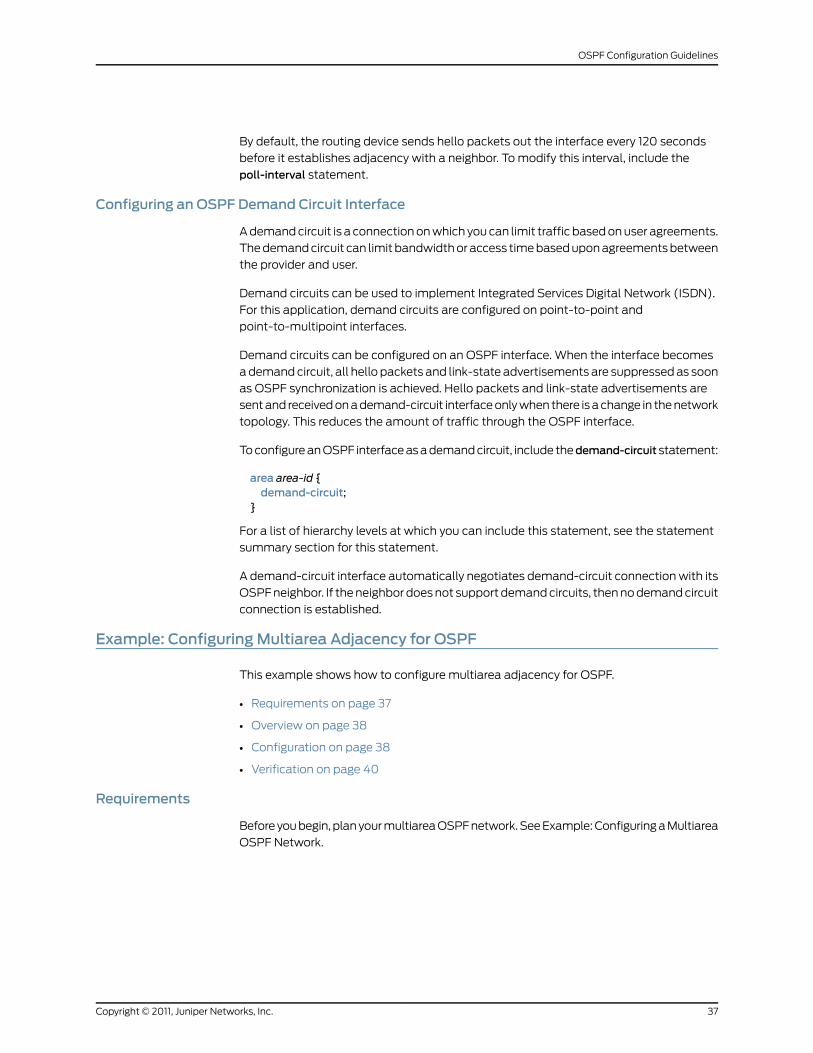
By default, the routing device sends hello packets out the interface every 120 seconds
before it establishes adjacency with a neighbor. To modify this interval, include the
poll-interval statement.
Configuring an OSPF Demand Circuit Interface
A demand circuit is a connection on which you can limit traffic based on user agreements.
The demand circuit can limit bandwidth or access time based upon agreements between
the provider and user.
Demand circuits can be used to implement Integrated Services Digital Network (ISDN).
For this application, demand circuits are configured on point-to-point and
point-to-multipoint interfaces.
Demand circuits can be configured on an OSPF interface. When the interface becomes
a demand circuit, all hello packets and link-state advertisements are suppressed as soon
as OSPF synchronization is achieved. Hello packets and link-state advertisements are
sent and received on a demand-circuit interface only when there is a change in the network
topology. This reduces the amount of traffic through the OSPF interface.
To configure an OSPF interface as a demand circuit, include thedemand-circuit statement:
area area-id {demand-circuit;
}
For a list of hierarchy levels at which you can include this statement, see the statement
summary section for this statement.
A demand-circuit interface automatically negotiates demand-circuit connection with its
OSPF neighbor. If the neighbor does not support demand circuits, then no demand circuit
connection is established.
Example: ConfiguringMultiarea Adjacency for OSPF
This example shows how to configure multiarea adjacency for OSPF.
• Requirements on page 37
• Overview on page 38
• Configuration on page 38
• Verification on page 40
Requirements
Before you begin, plan your multiarea OSPF network. See Example: Configuring a Multiarea
OSPF Network.
37Copyright © 2011, Juniper Networks, Inc.
OSPF Configuration Guidelines
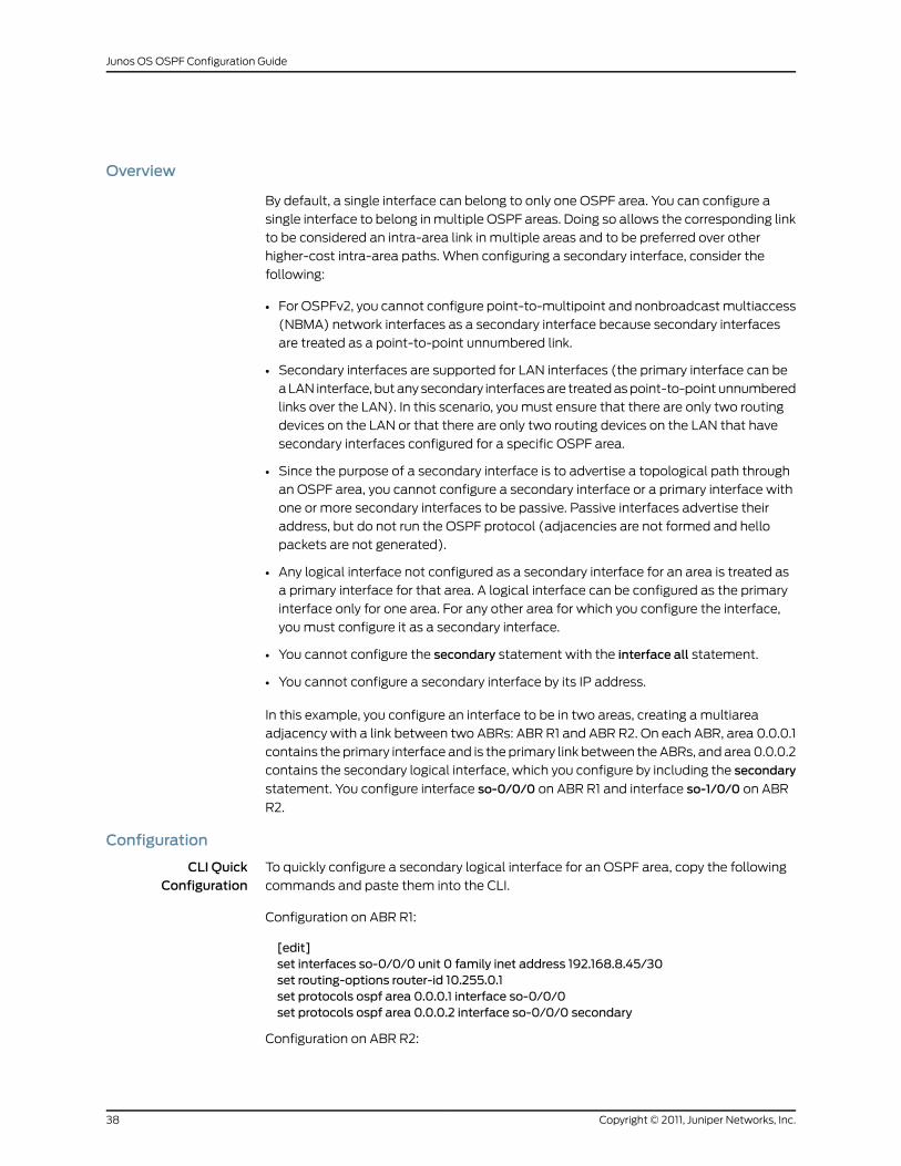
Overview
By default, a single interface can belong to only one OSPF area. You can configure a
single interface to belong in multiple OSPF areas. Doing so allows the corresponding link
to be considered an intra-area link in multiple areas and to be preferred over other
higher-cost intra-area paths. When configuring a secondary interface, consider the
following:
• For OSPFv2, you cannot configure point-to-multipoint and nonbroadcast multiaccess
(NBMA) network interfaces as a secondary interface because secondary interfaces
are treated as a point-to-point unnumbered link.
• Secondary interfaces are supported for LAN interfaces (the primary interface can be
a LAN interface, but any secondary interfaces are treated as point-to-point unnumbered
links over the LAN). In this scenario, you must ensure that there are only two routing
devices on the LAN or that there are only two routing devices on the LAN that have
secondary interfaces configured for a specific OSPF area.
• Since the purpose of a secondary interface is to advertise a topological path through
an OSPF area, you cannot configure a secondary interface or a primary interface with
one or more secondary interfaces to be passive. Passive interfaces advertise their
address, but do not run the OSPF protocol (adjacencies are not formed and hello
packets are not generated).
• Any logical interface not configured as a secondary interface for an area is treated as
a primary interface for that area. A logical interface can be configured as the primary
interface only for one area. For any other area for which you configure the interface,
you must configure it as a secondary interface.
• You cannot configure the secondary statement with the interface all statement.
• You cannot configure a secondary interface by its IP address.
In this example, you configure an interface to be in two areas, creating a multiarea
adjacency with a link between two ABRs: ABR R1 and ABR R2. On each ABR, area 0.0.0.1
contains the primary interface and is the primary link between the ABRs, and area 0.0.0.2
contains the secondary logical interface, which you configure by including the secondary
statement. You configure interface so-0/0/0 on ABR R1 and interface so-1/0/0 on ABR
R2.
Configuration
CLI QuickConfiguration
To quickly configure a secondary logical interface for an OSPF area, copy the following
commands and paste them into the CLI.
Configuration on ABR R1:
[edit]set interfaces so-0/0/0 unit 0 family inet address 192.168.8.45/30set routing-options router-id 10.255.0.1set protocols ospf area 0.0.0.1 interface so-0/0/0set protocols ospf area 0.0.0.2 interface so-0/0/0 secondary
Configuration on ABR R2:
Copyright © 2011, Juniper Networks, Inc.38
Junos OS OSPF Configuration Guide
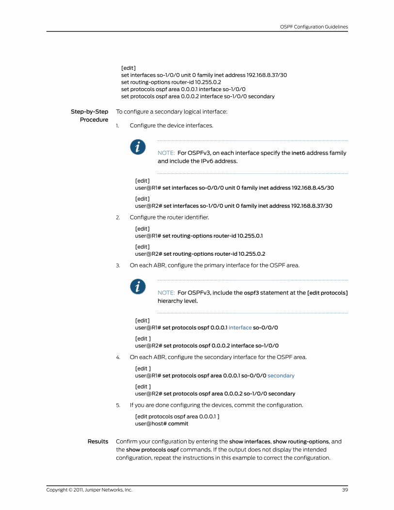
[edit]set interfaces so-1/0/0 unit 0 family inet address 192.168.8.37/30set routing-options router-id 10.255.0.2set protocols ospf area 0.0.0.1 interface so-1/0/0set protocols ospf area 0.0.0.2 interface so-1/0/0 secondary
Step-by-StepProcedure
To configure a secondary logical interface:
Configure the device interfaces.1.
NOTE: For OSPFv3, on each interface specify the inet6 address family
and include the IPv6 address.
[edit]user@R1# set interfaces so-0/0/0 unit 0 family inet address 192.168.8.45/30
[edit]user@R2# set interfaces so-1/0/0 unit 0 family inet address 192.168.8.37/30
2. Configure the router identifier.
[edit]user@R1# set routing-options router-id 10.255.0.1
[edit]user@R2# set routing-options router-id 10.255.0.2
3. On each ABR, configure the primary interface for the OSPF area.
NOTE: For OSPFv3, include the ospf3 statement at the [edit protocols]
hierarchy level.
[edit]user@R1# set protocols ospf 0.0.0.1 interface so-0/0/0
[edit ]user@R2# set protocols ospf 0.0.0.2 interface so-1/0/0
4. On each ABR, configure the secondary interface for the OSPF area.
[edit ]user@R1# set protocols ospf area 0.0.0.1 so-0/0/0 secondary
[edit ]user@R2# set protocols ospf area 0.0.0.2 so-1/0/0 secondary
5. If you are done configuring the devices, commit the configuration.
[edit protocols ospf area 0.0.0.1 ]user@host# commit
Results Confirm your configuration by entering the show interfaces, show routing-options, and
the show protocols ospf commands. If the output does not display the intended
configuration, repeat the instructions in this example to correct the configuration.
39Copyright © 2011, Juniper Networks, Inc.
OSPF Configuration Guidelines
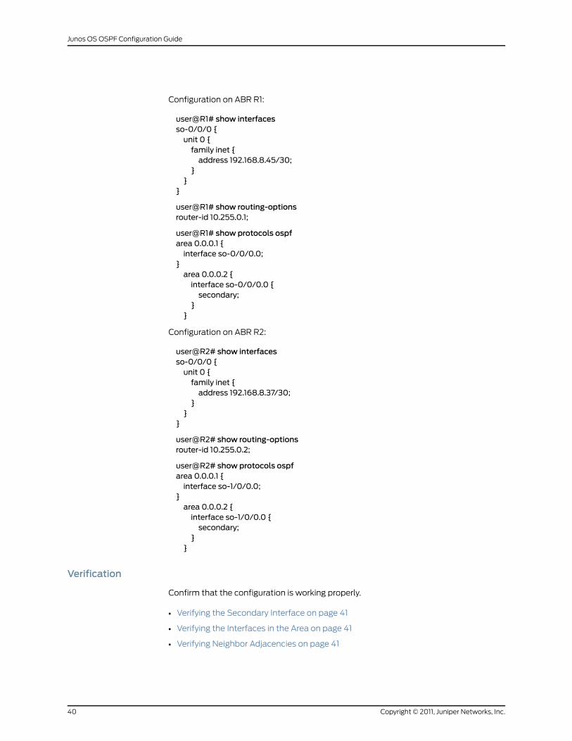
Configuration on ABR R1:
user@R1# show interfacesso-0/0/0 {unit 0 {family inet {address 192.168.8.45/30;
}}
}
user@R1# show routing-optionsrouter-id 10.255.0.1;
user@R1# show protocols ospfarea 0.0.0.1 {interface so-0/0/0.0;
}area 0.0.0.2 {interface so-0/0/0.0 {secondary;
}}
Configuration on ABR R2:
user@R2# show interfacesso-0/0/0 {unit 0 {family inet {address 192.168.8.37/30;
}}
}
user@R2# show routing-optionsrouter-id 10.255.0.2;
user@R2# show protocols ospfarea 0.0.0.1 {interface so-1/0/0.0;
}area 0.0.0.2 {interface so-1/0/0.0 {secondary;
}}
Verification
Confirm that the configuration is working properly.
• Verifying the Secondary Interface on page 41
• Verifying the Interfaces in the Area on page 41
• Verifying Neighbor Adjacencies on page 41
Copyright © 2011, Juniper Networks, Inc.40
Junos OS OSPF Configuration Guide
Verifying the Secondary Interface
Purpose Verify that the secondary interface appears for the configured area. The Secondary field
displays if the interface is configured as a secondary interface. The output might also
show the same interface listed in multiple areas.
Action From operational mode, enter the show ospf interface detail command for OSPFv2, and
enter the show ospf3 interface detail command for OSPFv3.
Verifying the Interfaces in the Area
Purpose Verify the interfaces configured for the specified area.
Action From operational mode, enter the showospf interfaceareaarea-id command for OSPFv2,
and enter the show ospf3 interface area area-id command for OSPFv3..
Verifying Neighbor Adjacencies
Purpose Verify the primary and secondary neighbor adjacencies. The Secondary field displays if
the neighbor is on a secondary interface.
Action From operational mode, enter the show ospf neighbor detail command for OSPFv2, and
enter the show ospf3 neighbor detail command for OSPFv3.
RelatedDocumentation
Multiarea Adjacency for OSPF•
• Understanding OSPF Areas and Backbone Areas
Example: ConfiguringMultiple Address Families for OSPFv3
This example shows how to configure multiple address families for OSPFv3.
• Requirements on page 41
• Overview on page 42
• Configuration on page 43
• Verification on page 44
Requirements
Before you begin:
• Configure the router identifiers for the devices in your OSPF network. See Example:
Configuring an OSPF Router Identifier.
• Configure a single-area OSPF network. See Example: Configuring a Single-Area OSPF
Network.
41Copyright © 2011, Juniper Networks, Inc.
OSPF Configuration Guidelines
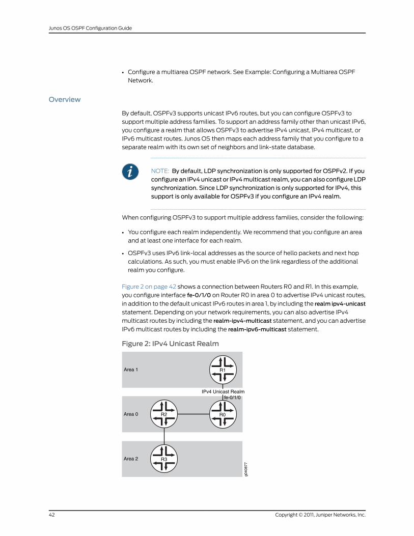
• Configure a multiarea OSPF network. See Example: Configuring a Multiarea OSPF
Network.
Overview
By default, OSPFv3 supports unicast IPv6 routes, but you can configure OSPFv3 to
support multiple address families. To support an address family other than unicast IPv6,
you configure a realm that allows OSPFv3 to advertise IPv4 unicast, IPv4 multicast, or
IPv6 multicast routes. Junos OS then maps each address family that you configure to a
separate realm with its own set of neighbors and link-state database.
NOTE: By default, LDP synchronization is only supported for OSPFv2. If youconfigurean IPv4unicastor IPv4multicast realm, youcanalsoconfigureLDPsynchronization. Since LDP synchronization is only supported for IPv4, thissupport is only available for OSPFv3 if you configure an IPv4 realm.
When configuring OSPFv3 to support multiple address families, consider the following:
• You configure each realm independently. We recommend that you configure an area
and at least one interface for each realm.
• OSPFv3 uses IPv6 link-local addresses as the source of hello packets and next hop
calculations. As such, you must enable IPv6 on the link regardless of the additional
realm you configure.
Figure 2 on page 42 shows a connection between Routers R0 and R1. In this example,
you configure interface fe-0/1/0 on Router R0 in area 0 to advertise IPv4 unicast routes,
in addition to the default unicast IPv6 routes in area 1, by including the realm ipv4-unicast
statement. Depending on your network requirements, you can also advertise IPv4
multicast routes by including the realm-ipv4-multicast statement, and you can advertise
IPv6 multicast routes by including the realm-ipv6-multicast statement.
Figure 2: IPv4 Unicast Realm
g040
877
R1
R0R2
R3
fe-0/1/0
Area 1
Area 0
Area 2
IPv4 Unicast Realm
Copyright © 2011, Juniper Networks, Inc.42
Junos OS OSPF Configuration Guide
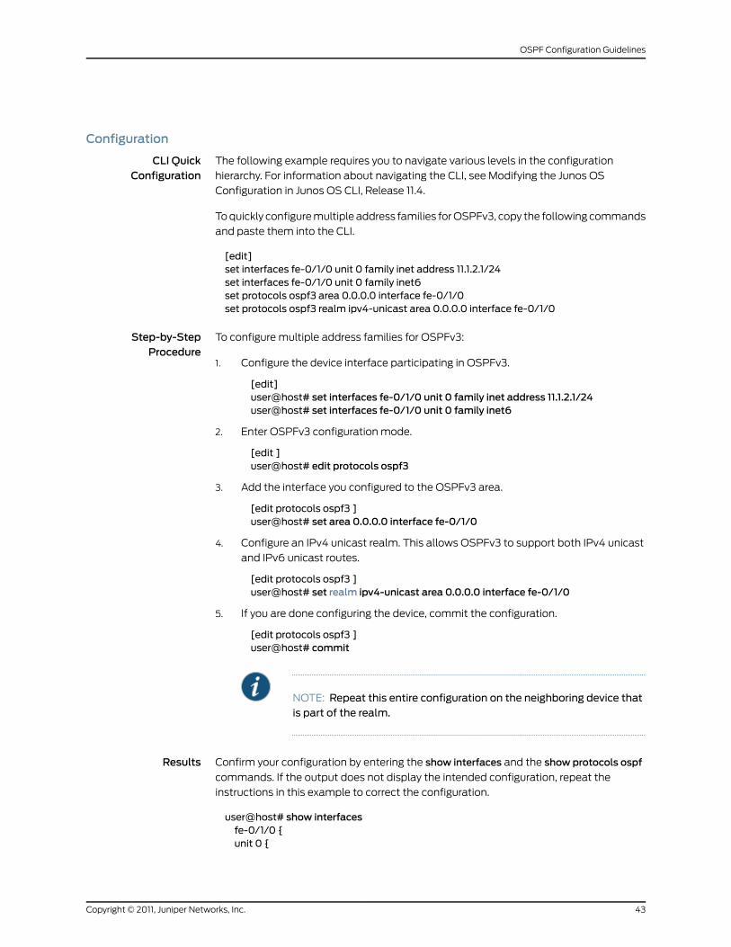
Configuration
CLI QuickConfiguration
The following example requires you to navigate various levels in the configuration
hierarchy. For information about navigating the CLI, see Modifying the Junos OS
Configuration in Junos OS CLI, Release 11.4.
To quickly configure multiple address families for OSPFv3, copy the following commands
and paste them into the CLI.
[edit]set interfaces fe-0/1/0 unit 0 family inet address 11.1.2.1/24set interfaces fe-0/1/0 unit 0 family inet6set protocols ospf3 area 0.0.0.0 interface fe-0/1/0set protocols ospf3 realm ipv4-unicast area 0.0.0.0 interface fe-0/1/0
Step-by-StepProcedure
To configure multiple address families for OSPFv3:
Configure the device interface participating in OSPFv3.1.
[edit]user@host# set interfaces fe-0/1/0 unit 0 family inet address 11.1.2.1/24user@host# set interfaces fe-0/1/0 unit 0 family inet6
2. Enter OSPFv3 configuration mode.
[edit ]user@host# edit protocols ospf3
3. Add the interface you configured to the OSPFv3 area.
[edit protocols ospf3 ]user@host# set area 0.0.0.0 interface fe-0/1/0
4. Configure an IPv4 unicast realm. This allows OSPFv3 to support both IPv4 unicast
and IPv6 unicast routes.
[edit protocols ospf3 ]user@host# set realm ipv4-unicast area 0.0.0.0 interface fe-0/1/0
5. If you are done configuring the device, commit the configuration.
[edit protocols ospf3 ]user@host# commit
NOTE: Repeat this entire configuration on the neighboring device thatis part of the realm.
Results Confirm your configuration by entering the show interfaces and the show protocols ospf
commands. If the output does not display the intended configuration, repeat the
instructions in this example to correct the configuration.
user@host# show interfacesfe-0/1/0 {unit 0 {
43Copyright © 2011, Juniper Networks, Inc.
OSPF Configuration Guidelines
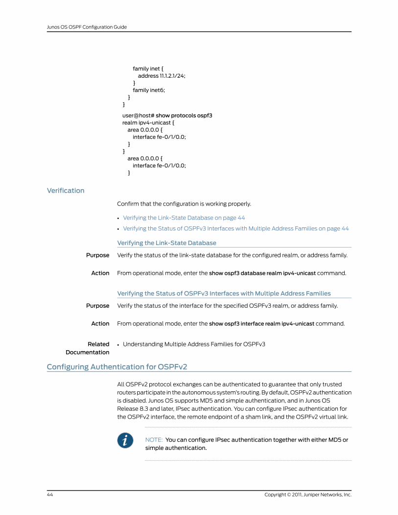
family inet {address 11.1.2.1/24;
}family inet6;
}}
user@host# show protocols ospf3realm ipv4-unicast {area 0.0.0.0 {interface fe-0/1/0.0;
}}area 0.0.0.0 {interface fe-0/1/0.0;
}
Verification
Confirm that the configuration is working properly.
• Verifying the Link-State Database on page 44
• Verifying the Status of OSPFv3 Interfaces with Multiple Address Families on page 44
Verifying the Link-State Database
Purpose Verify the status of the link-state database for the configured realm, or address family.
Action From operational mode, enter the show ospf3 database realm ipv4-unicast command.
Verifying the Status of OSPFv3 Interfaces with Multiple Address Families
Purpose Verify the status of the interface for the specified OSPFv3 realm, or address family.
Action From operational mode, enter the show ospf3 interface realm ipv4-unicast command.
RelatedDocumentation
Understanding Multiple Address Families for OSPFv3•
Configuring Authentication for OSPFv2
All OSPFv2 protocol exchanges can be authenticated to guarantee that only trusted
routers participate in the autonomous system’s routing. By default, OSPFv2 authentication
is disabled. Junos OS supports MD5 and simple authentication, and in Junos OS
Release 8.3 and later, IPsec authentication. You can configure IPsec authentication for
the OSPFv2 interface, the remote endpoint of a sham link, and the OSPFv2 virtual link.
NOTE: You can configure IPsec authentication together with either MD5 orsimple authentication.
Copyright © 2011, Juniper Networks, Inc.44
Junos OS OSPF Configuration Guide
• To enable IPsec authentication for an OSPFv2 interface, include the ipsec-sa name
statement for a specific interface:
interface interface-name ipsec-sa name;
• To enable IPsec authentication for a remote sham link, include the ispec-sa name
statement for the remote end point of the sham link:
sham-link-remote address ipsec-sa name;
NOTE: If a Layer 3 VPN configuration hasmultiple sham links with thesame remote endpoint IP address, youmust configure the same IPsecsecurity association for all the remote endpoints. You configure aLayer 3 VPN at the [edit routing-instances routing-instance-name
instance-type] hierarchy level. For more information about Layer 3 VPNs,
see the Junos OS VPNs Configuration Guide.
• To enable IPsec authentication for a virtual link, include the ipsec-sa name statement
for a specific virtual link:
virtual-link neighbor-id router-id transit-area area-id ipsec-sa name;
For a list of hierarchy levels at which you can include these statements, see the statement
summary sections for these statements.
You specify the IPsec authentication name by including the ipsec-sa name statement
where name is the name of the IPsec security association. You configure the actual IPsec
authentication separately. Only manual security associations (SAs) are supported for
OSPFv2 authentication using IPsec. Dynamic IKE SAs are not supported. For more
information about IPsec, see the JunosOSSystemBasics ConfigurationGuide, the JunosOS
Services Interfaces Configuration Guide, and the Junos OS IPsec Feature Guide.
The following restrictions also apply to IPsec authentication for OSPFv2:
• Only IPsec transport mode is supported. Tunnel mode is not supported.
• Because only bidirectional manual SAs are supported, all OSPFv2 peers must be
configured with the same IPsec SA. You configure a manual bidirectional SA at the
[edit security ipsec] hierarchy level.
• You must also configure the same IPsec SA for all virtual links with the same remote
endpoint address, for all neighbors on OSPF nonbroadcast multiaccess (NBMA) or
point-to-multipoint (P2MP) links, and for every subnet that is part of a broadcast link.
• OSPFv2 peer interfaces are not supported.
Simple authentication uses a text password that is included in the transmitted packet.
The receiving router uses an authentication key (password) to verify the packet.
The MD5 algorithm creates an encoded checksum that is included in the transmitted
packet. The receiving router uses an authentication key (password) to verify the packet.
45Copyright © 2011, Juniper Networks, Inc.
OSPF Configuration Guidelines
For MD5 authentication to work, both the receiving and transmitting routers must have
the same MD5 key. Define an MD5 key for each interface. If MD5 is enabled on an interface,
that interface accepts routing updates only if MD5 authentication succeeds; otherwise,
updates are rejected. The key ID can be set to any value between 0 and 255, with a default
value of 0. The router only accepts OSPFv2 packets sent using the same key ID that is
defined for that interface.
To enable authentication and specify an authentication method as well as a key
(password) for an OSPF interface or virtual link, include the authentication statement
and either a single simple-password statement or one or more md5 statements:
authentication {simple-password key;
}authentication {md5 key {key [ key-values ] {start-time time;
}}
For a list of hierarchy levels at which you can include these statements, see the statement
summary sections for these statements.
A simple password and MD5 key are mutually exclusive. You can configure only one
simple password but configure multiple MD5 keys.
The simple key (password) can be from 1 through 8 characters long. Each MD5 key is
identified by a key identifier. The MD5 key value can be from 1 through 16 characters long.
Characters can include ASCII strings. If you include spaces, enclose all characters in
quotation marks (“ ”).
As part of your security measures, you can change MD5 keys. You can do this by configuring
multiple MD5 keys, each with a unique key ID, and setting the date and time to switch to
the new key. Each unique MD5 key has a unique ID. The ID is used by the receiver of the
OSPF packet to determine which key to use for authentication. The key identifier, which
is required for MD5 authentication, specifies the identifier associated with the MD5 key.
The start time specifies when to start using the MD5 key. This is optional. The start-time
option enables you to configure a smooth transition mechanism for multiple keys. The
start time is relevant for transmission but not for receiving OSPF packets.
See the following sections:
• Example: Configuring IPsec Authentication for an OSPFv2 Interface on page 46
• Example: Configuring a Transition of MD5 Keys on page 47
• Example: Configuring MD5 Authentication on page 47
Example: Configuring IPsec Authentication for an OSPFv2 Interface
Configure IPsec authentication for OSPFv2 interface so-0/2/0.0. Include the name of
the manual SA sa1 that you configure at the [edit security ipsec] hierarchy level.
Copyright © 2011, Juniper Networks, Inc.46
Junos OS OSPF Configuration Guide
[edit protocols ospf]area 0.0.0.0 {interface so-0/2/0.0 {ipsec-sa sa-1;
}}
Example: Configuring a Transition of MD5 Keys
Configure new keys to take effect at 12:01 AM on the first day of the next three months:
[edit protocols ospf area 0.0.0.0 interface fe-0/0/1]authentication {md5 1 {key $2001HaL;
}}authentication {md5 2 {key NeWpsswdFEB {start-time 2006-02-01.00:01;
}}
}authentication {md5 3 {key NeWpsswdMAR {start-time 2006-03-01.00:01;
}}
}authentication {md5 4 {key NeWpsswdAPR {start-time 2006-04-01.00:01;
}}
}
Set the same passwords and transition dates and times on all the routers in the area so
that OSPF adjacencies remain active.
Example: ConfiguringMD5 Authentication
Configure MD5 authentication for OSPF:
[edit protocols ospf]area 0.0.0.0 {interface fxp0.0 {disable;
}interface t1-0/2/1.0 {authentication {md5 3 key "$9$6gBqCtOW87YgJEcyKW8Vb" start-time 2002-11-19.10:00;# SECRET-DATA
md5 2 key "$9$DJHkP5T3/A0Uj6A0Irl"; # SECRET-DATA
47Copyright © 2011, Juniper Networks, Inc.
OSPF Configuration Guidelines
}}reference-bandwidth 4g;traceoptions {file ospf size 5mworld-readable;flag error;
}}
Configuring Authentication for OSPFv3
OSPF version 3 (OSPFv3) provides a method for protecting and securing the OSPF traffic
through the router. OSPFv3 uses the IP authentication header (AH) and the IP
Encapsulating Security Payload (ESP) to authenticate routing information.
Use ESP with NULL encryption to provide authentication to the OSPFv3 protocol headers
only. Use AH to provide authentication to the OSPFv3 protocol headers, portions of the
IPv6 header, and portions of the extension headers. Use ESP with non-NULL encryption
for full confidentiality.
OSPFv3 authentication uses static keyed IP Security (IPsec) security associations (SAs)
similar to BGP IPsec. Tunnel mode SAs and dynamic IPsec SAs using Internet Key
Exchange (IKE) authentication are not supported. Dynamic keyed IPsec SAs run on the
Routing Engine and do not require a services PIC.
To apply authentication, include the ipsec-sa statement for a specific OSPFv3 interface:
interface interface-name ipsec-sa name;
For a list of hierarchy levels at which you can include these statements, see the statement
summary sections for these statements.
You specify the IPsec authentication name by including the name option. You configure
the actual IPsec authentication separately.
RelatedDocumentation
Junos OS System Basics Configuration Guide•
• Junos OS Services Interfaces Configuration Guide
Example: Limiting the Number of Prefixes Exported to OSPF
This example shows how to limit the number of prefixes exported to OSPF.
• Requirements on page 49
• Overview on page 49
• Configuration on page 49
• Verification on page 50
Copyright © 2011, Juniper Networks, Inc.48
Junos OS OSPF Configuration Guide
Requirements
Before you begin:
• Configure the device interfaces. See the JunosOSNetwork InterfacesConfigurationGuide.
• Configure the router identifiers for the devices in your OSPF network. See Example:
Configuring an OSPF Router Identifier.
• Control OSPF designated router election. See “Example: Controlling OSPF Designated
Router Election” on page 50
• Configure a single-area OSPF network. See Example: Configuring a Single-Area OSPF
Network.
• Configure a multiarea OSPF network. See Example: Configuring a Multiarea OSPF
Network.
Overview
By default, there is no limit to the number of prefixes (routes) that can be exported into
OSPF. By allowing any number of routes to be exported into OSPF, the routing device
can become overwhelmed and potentially flood an excessive number of routes into an
area.
You can limit the number of routes exported into OSPF to minimize the load on the routing
device and prevent this potential problem. If the routing device exceeds the configured
prefix export value, the routing device purges the external prefixes and enters into an
overload state. This state ensures that the routing device is not overwhelmed as it
attempts to process routing information. The prefix export limit number can be a value
from 0 through 4,294,967,295.
In this example, you configure a prefix export limit of 100,000 by including the
prefix-export-limit statement.
Configuration
CLI QuickConfiguration
To quickly limit the number of prefixes exported to OSPF, copy the following command
and paste it into the CLI.
[edit]set protocols ospf prefix-export-limit 100000
Step-by-StepProcedure
To limit the number of prefixes exported to OSPF:
Configure the prefix export limit value.1.
NOTE: For OSPFv3, include the ospf3 statement at the [edit protocols]
hierarchy level.
[edit]
49Copyright © 2011, Juniper Networks, Inc.
OSPF Configuration Guidelines
user@host# set protocols ospf prefix-export-limit 100000
2. If you are done configuring the device, commit the configuration.
[edit]user@host# commit
Results Confirm your configuration by entering the show protocols ospf command. If the output
does not display the intended configuration, repeat the instructions in this example to
correct the configuration.
user@host# show protocols ospfprefix-export-limit 100000;
To confirm your OSPFv3 configuration, enter the show protocols ospf3 command.
Verification
Confirm that the configuration is working properly.
Verifying the Prefix Export Limit
Purpose Verify the prefix export counter that displays the number or routes exported into OSPF.
Action From operational mode, enter the show ospf overview command for OSPFv2, and enter
the show ospf3 overview command for OSPFv3.
RelatedDocumentation
OSPF Configuration Overview•
• Understanding OSPF Route Summarization
• Example: Summarizing Ranges of Routes in OSPF Link-State Advertisements on
page 52
• Example: Summarizing Ranges of Routes in OSPF Link-State Advertisements on
page 52
Example: Controlling OSPF Designated Router Election
This example shows how to control OSPF designated router election.
• Requirements on page 50
• Overview on page 51
• Configuration on page 51
• Verification on page 52
Requirements
Before you begin:
• Configure the device interfaces. See the JunosOSNetwork InterfacesConfigurationGuide.
Copyright © 2011, Juniper Networks, Inc.50
Junos OS OSPF Configuration Guide
• Configure the router identifiers for the devices in your OSPF network. See Example:
Configuring an OSPF Router Identifier.
Overview
This example shows how to control OSPF designated router election. Within the example,
you set the OSPF interface to ge-/0/0/1 and the device priority to 200. The higher the
priority value, the greater likelihood the routing device will become the designated router.
By default, routing devices have a priority of 128. A priority of 0 marks the routing device
as ineligible to become the designated router. A priority of 1 means the routing device
has the least chance of becoming a designated router.
Configuration
CLI QuickConfiguration
To quickly configure an OSPF designated router election, copy the following command
and paste it into the CLI.
[edit]set protocols ospf area 0.0.0.3 interface ge-0/0/1 priority 200
Step-by-StepProcedure
To control OSPF designated router election:
Configure an OSPF interface and specify the device priority.1.
NOTE: To specify an OSPFv3 interface, include the ospf3 statement at
the [edit protocols] hierarchy level.
[edit]user@host# set protocols ospf area 0.0.0.3 interface ge-0/0/1 priority 200
2. If you are done configuring the device, commit the configuration.
[edit]user@host# commit
Results Confirm your configuration by entering the show protocols ospf command. If the output
does not display the intended configuration, repeat the instructions in this example to
correct the configuration.
user@host# show protocols ospfarea 0.0.0.3 {interface ge-0/0/1.0 {priority 200;
}}
To confirm your OSPFv3 configuration, enter the show protocols ospf3 command.
51Copyright © 2011, Juniper Networks, Inc.
OSPF Configuration Guidelines
Verification
Confirm that the configuration is working properly.
• Verifying the Designated Router Election on page 52
Verifying the Designated Router Election
Purpose Based on the priority you configured for a specific OSPF interface, you can confirm the
address of the area’s designated router. The DR ID, DR, or DR-ID field displays the address
of the area’s designated router. The BDR ID, BDR, or BDR-ID field displays the address
of the backup designated router.
Action From operational mode, enter the show ospf interface and the show ospf neighbor
commands for OSPFv2, and enter the showospf3 interface and the showospf3 neighbor
commands for OSPFv3.
RelatedDocumentation
OSPF Configuration Overview•
• OSPF Designated Router Overview on page 13
• Example: Configuring an OSPF Router Identifier
Example: Summarizing Ranges of Routes in OSPF Link-State Advertisements
This example shows how to summarize routes sent into the backbone area.
• Requirements on page 52
• Overview on page 52
• Configuration on page 53
• Verification on page 57
Requirements
Before you begin:
• Configure the router identifiers for the devices in your OSPF network. See Example:
Configuring an OSPF Router Identifier.
• Control OSPF designated router election. See “Example: Controlling OSPF Designated
Router Election” on page 50
• Configure a static route. See Examples: Configuring Static Routes in the Junos OS
Routing Protocols Configuration Guide.
Overview
You can summarize a range of IP addresses to minimize the size of the backbone router’s
link-state database. All routes that match the specified area range are filtered at the
area boundary, and the summary is advertised in their place.
Copyright © 2011, Juniper Networks, Inc.52
Junos OS OSPF Configuration Guide
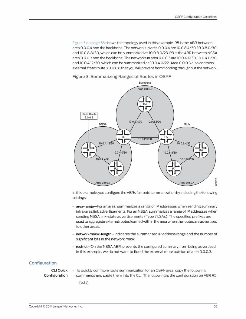
Figure 3 on page 53 shows the topology used in this example. R5 is the ABR between
area 0.0.0.4 and the backbone. The networks in area 0.0.0.4 are 10.0.8.4/30, 10.0.8.0/30,
and 10.0.8.8/30, which can be summarized as 10.0.8.0/23. R3 is the ABR between NSSA
area 0.0.0.3 and the backbone. The networks in area 0.0.0.3 are 10.0.4.4/30, 10.0.4.0/30,
and 10.0.4.12/30, which can be summarized as 10.0.4.0/22. Area 0.0.0.3 also contains
external static route 3.0.0.0.8 that you will prevent from flooding throughout the network.
Figure 3: Summarizing Ranges of Routes in OSPF
Area 0.0.0.3 Area 0.0.0.4
R2 R7
R6
Area 0.0.0.0
R4
R3 R510.0.2.0/30
10.0.8.8/30
10.0.8.0/30
10.0.8.4/3010.0.4.12/30
10.0.4.4/30
10.0.4.0/30
10.0.2.8/3010.0.2.4/30NSSA Stub
Backbone
g040
889
Static Route3.0.0.8
R1
In this example, you configure the ABRs for route summarization by including the following
settings:
• area-range—For an area, summarizes a range of IP addresses when sending summary
intra-area link advertisements. For an NSSA, summarizes a range of IP addresses when
sending NSSA link-state advertisements (Type 7 LSAs). The specified prefixes are
used to aggregate external routes learned within the area when the routes are advertised
to other areas.
• network/mask-length—Indicates the summarized IP address range and the number of
significant bits in the network mask.
• restrict—On the NSSA ABR, prevents the configured summary from being advertised.
In this example, we do not want to flood the external route outside of area 0.0.0.3.
Configuration
CLI QuickConfiguration
To quickly configure route summarization for an OSPF area, copy the following
commands and paste them into the CLI. The following is the configuration on ABR R5:
•
[edit]
53Copyright © 2011, Juniper Networks, Inc.
OSPF Configuration Guidelines
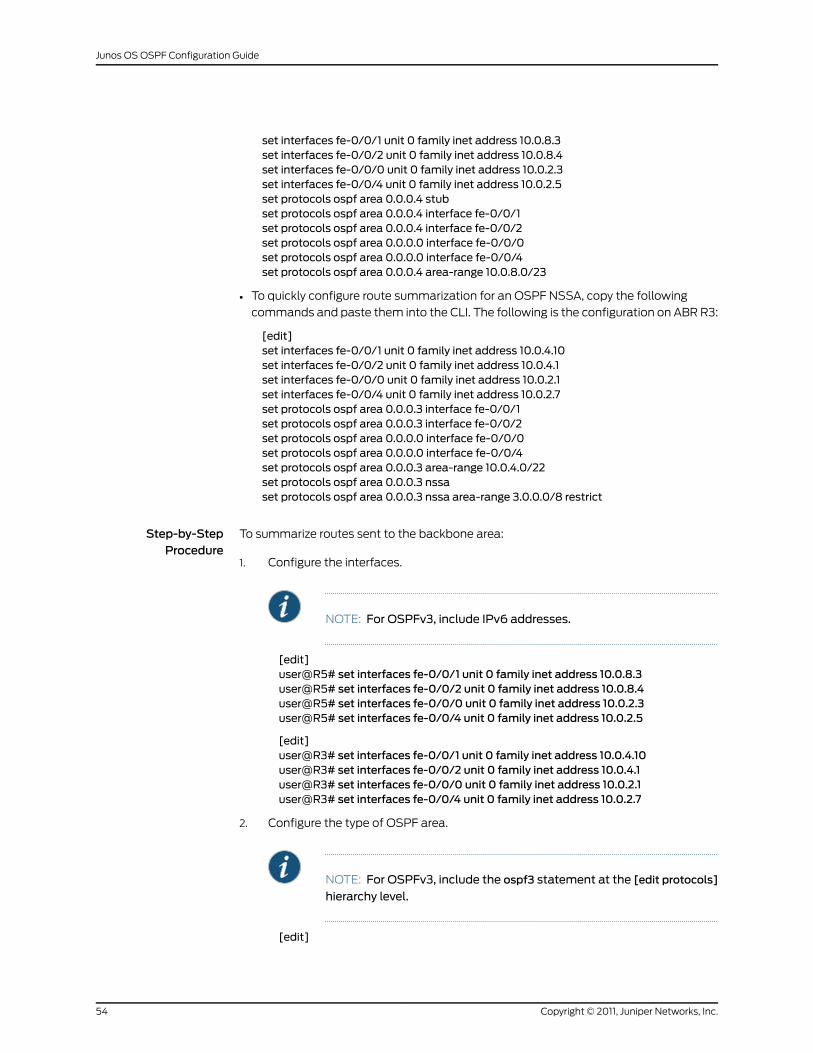
set interfaces fe-0/0/1 unit 0 family inet address 10.0.8.3set interfaces fe-0/0/2 unit 0 family inet address 10.0.8.4set interfaces fe-0/0/0 unit 0 family inet address 10.0.2.3set interfaces fe-0/0/4 unit 0 family inet address 10.0.2.5set protocols ospf area 0.0.0.4 stubset protocols ospf area 0.0.0.4 interface fe-0/0/1set protocols ospf area 0.0.0.4 interface fe-0/0/2set protocols ospf area 0.0.0.0 interface fe-0/0/0set protocols ospf area 0.0.0.0 interface fe-0/0/4set protocols ospf area 0.0.0.4 area-range 10.0.8.0/23
• To quickly configure route summarization for an OSPF NSSA, copy the following
commands and paste them into the CLI. The following is the configuration on ABR R3:
[edit]set interfaces fe-0/0/1 unit 0 family inet address 10.0.4.10set interfaces fe-0/0/2 unit 0 family inet address 10.0.4.1set interfaces fe-0/0/0 unit 0 family inet address 10.0.2.1set interfaces fe-0/0/4 unit 0 family inet address 10.0.2.7set protocols ospf area 0.0.0.3 interface fe-0/0/1set protocols ospf area 0.0.0.3 interface fe-0/0/2set protocols ospf area 0.0.0.0 interface fe-0/0/0set protocols ospf area 0.0.0.0 interface fe-0/0/4set protocols ospf area 0.0.0.3 area-range 10.0.4.0/22set protocols ospf area 0.0.0.3 nssaset protocols ospf area 0.0.0.3 nssa area-range 3.0.0.0/8 restrict
Step-by-StepProcedure
To summarize routes sent to the backbone area:
Configure the interfaces.1.
NOTE: For OSPFv3, include IPv6 addresses.
[edit]user@R5# set interfaces fe-0/0/1 unit 0 family inet address 10.0.8.3user@R5# set interfaces fe-0/0/2 unit 0 family inet address 10.0.8.4user@R5# set interfaces fe-0/0/0 unit 0 family inet address 10.0.2.3user@R5# set interfaces fe-0/0/4 unit 0 family inet address 10.0.2.5
[edit]user@R3# set interfaces fe-0/0/1 unit 0 family inet address 10.0.4.10user@R3# set interfaces fe-0/0/2 unit 0 family inet address 10.0.4.1user@R3# set interfaces fe-0/0/0 unit 0 family inet address 10.0.2.1user@R3# set interfaces fe-0/0/4 unit 0 family inet address 10.0.2.7
2. Configure the type of OSPF area.
NOTE: For OSPFv3, include the ospf3 statement at the [edit protocols]
hierarchy level.
[edit]
Copyright © 2011, Juniper Networks, Inc.54
Junos OS OSPF Configuration Guide
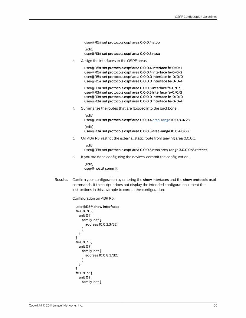
user@R5# set protocols ospf area 0.0.0.4 stub
[edit]user@R3# set protocols ospf area 0.0.0.3 nssa
3. Assign the interfaces to the OSPF areas.
user@R5# set protocols ospf area 0.0.0.4 interface fe-0/0/1user@R5# set protocols ospf area 0.0.0.4 interface fe-0/0/2user@R5# set protocols ospf area 0.0.0.0 interface fe-0/0/0user@R5# set protocols ospf area 0.0.0.0 interface fe-0/0/4
user@R3# set protocols ospf area 0.0.0.3 interface fe-0/0/1user@R3# set protocols ospf area 0.0.0.3 interface fe-0/0/2user@R3# set protocols ospf area 0.0.0.0 interface fe-0/0/0user@R3# set protocols ospf area 0.0.0.0 interface fe-0/0/4
4. Summarize the routes that are flooded into the backbone.
[edit]user@R5# set protocols ospf area 0.0.0.4 area-range 10.0.8.0/23
[edit]user@R3# set protocols ospf area 0.0.0.3 area-range 10.0.4.0/22
5. On ABR R3, restrict the external static route from leaving area 0.0.0.3.
[edit]user@R3# set protocols ospf area 0.0.0.3 nssa area-range 3.0.0.0/8 restrict
6. If you are done configuring the devices, commit the configuration.
[edit]user@host# commit
Results Confirm your configuration by entering the show interfaces and the show protocols ospf
commands. If the output does not display the intended configuration, repeat the
instructions in this example to correct the configuration.
Configuration on ABR R5:
user@R5# show interfacesfe-0/0/0 {unit 0 {family inet {address 10.0.2.3/32;
}}
}fe-0/0/1 {unit 0 {family inet {address 10.0.8.3/32;
}}
}fe-0/0/2 {unit 0 {family inet {
55Copyright © 2011, Juniper Networks, Inc.
OSPF Configuration Guidelines
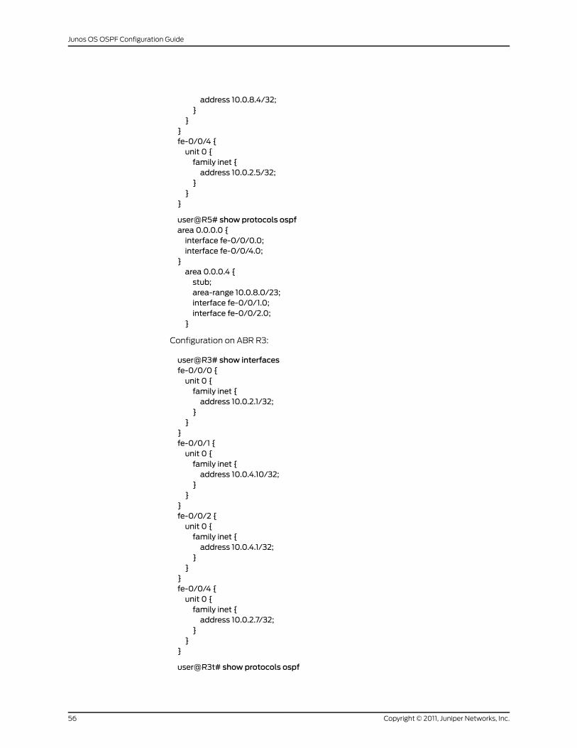
address 10.0.8.4/32;}
}}fe-0/0/4 {unit 0 {family inet {address 10.0.2.5/32;
}}
}
user@R5# show protocols ospfarea 0.0.0.0 {interface fe-0/0/0.0;interface fe-0/0/4.0;
}area 0.0.0.4 {stub;area-range 10.0.8.0/23;interface fe-0/0/1.0;interface fe-0/0/2.0;
}
Configuration on ABR R3:
user@R3# show interfacesfe-0/0/0 {unit 0 {family inet {address 10.0.2.1/32;
}}
}fe-0/0/1 {unit 0 {family inet {address 10.0.4.10/32;
}}
}fe-0/0/2 {unit 0 {family inet {address 10.0.4.1/32;
}}
}fe-0/0/4 {unit 0 {family inet {address 10.0.2.7/32;
}}
}
user@R3t# show protocols ospf
Copyright © 2011, Juniper Networks, Inc.56
Junos OS OSPF Configuration Guide
area 0.0.0.0 {interface fe-0/0/0.0;interface fe-0/0/4.0;
}area 0.0.0.3 {nssa {area-range 3.0.0.0/8 restrict;
}area-range 10.0.4.0/22;interface fe-0/0/1.0;interface fe-0/0/2.0;
}
To confirm your OSPFv3 configuration, enter the show interfaces and show protocols
ospf3 commands.
Verification
Confirm that the configuration is working properly.
Verifying the Summarized Route
Purpose Verify that the routes you configured for route summarization are being aggregated by
the ABRs before the routes enter the backbone area. Confirm route summarization by
checking the entries of the OSPF link-state database for the routing devices in the
backbone.
Action From operational mode, enter the show ospf database command for OSPFv2, and enter
the show ospf3 database command for OSPFv3.
RelatedDocumentation
OSPF Configuration Overview•
• Understanding OSPF Route Summarization
• Example: Limiting the Number of Prefixes Exported to OSPF on page 48
Example: Controlling the Cost of Individual OSPF Network Segments
This example shows how to control the cost of individual OSPF network segments.
• Requirements on page 57
• Overview on page 58
• Configuration on page 59
• Verification on page 61
Requirements
Before you begin:
57Copyright © 2011, Juniper Networks, Inc.
OSPF Configuration Guidelines
• Configure the device interfaces. See the JunosOSNetwork InterfacesConfigurationGuide.
• Configure the router identifiers for the devices in your OSPF network. See Example:
Configuring an OSPF Router Identifier.
• Control OSPF designated router election. See “Example: Controlling OSPF Designated
Router Election” on page 50
• Configure a single-area OSPF network. See Example: Configuring a Single-Area OSPF
Network.
Overview
All OSPF interfaces have a cost, which is a routing metric that is used in the link-state
calculation. Routes with lower total path metrics are preferred to those with higher path
metrics. In this example, we explore how to control the cost of OSPF network segments.
By default, OSPF assigns a default cost metric of 1 to any link faster than 100 Mbps, and
a default cost metric of 0 to the loopback interface (lo0). No bandwidth is associated
with the loopback interface. This means that all interfaces faster than 100 Mbps have
the same default cost metric of 1. If multiple equal-cost paths exist between a source
and destination address, OSPF routes packets along each path alternately, in round-robin
fashion.
Having the same default metric might not be a problem if all of the interfaces are running
at the same speed. If the interfaces operate at different speeds, you might notice that
traffic is not routed over the fastest interface because OSPF equally routes packets
across the different interfaces. For example, if your routing device has Fast Ethernet and
Gigabit Ethernet interfaces running OSPF, each of these interfaces have a default cost
metric of 1.
In the first example, you set the reference bandwidth to 10g (10 Gbps, as denoted by
10,000,000,000 bits) by including the reference-bandwidth statement. With this
configuration, OSPF assigns the Fast Ethernet interface a default metric of 100, and the
Gigabit Ethernet interface a metric of 10. Since the Gigabit Ethernet interface has the
lowest metric, OSPF selects it when routing packets. The range is 9600 through
1,000,000,000,000 bits.
Figure 4 on page 59 shows three routing devices in area 0.0.0.0 and assumes that the
link between Device R2 and Device R3 is congested with other traffic. You can also control
the flow of packets across the network by manually assigning a metric to a particular
path segment. Any value you configure for the metric overrides the default behavior of
using the reference-bandwidth value to calculate the route cost for that interface. To
prevent the traffic from Device R3 going directly to Device R2, you adjust the metric on
the interface on Device R3 that connects with Device R1 so that all traffic goes through
Device R1.
In the second example, you set the metric to 5 on interface fe-1/0/1 on Device R3 that
connects with Device R1 by including themetric statement. The range is 1 through 65,535.
Copyright © 2011, Juniper Networks, Inc.58
Junos OS OSPF Configuration Guide
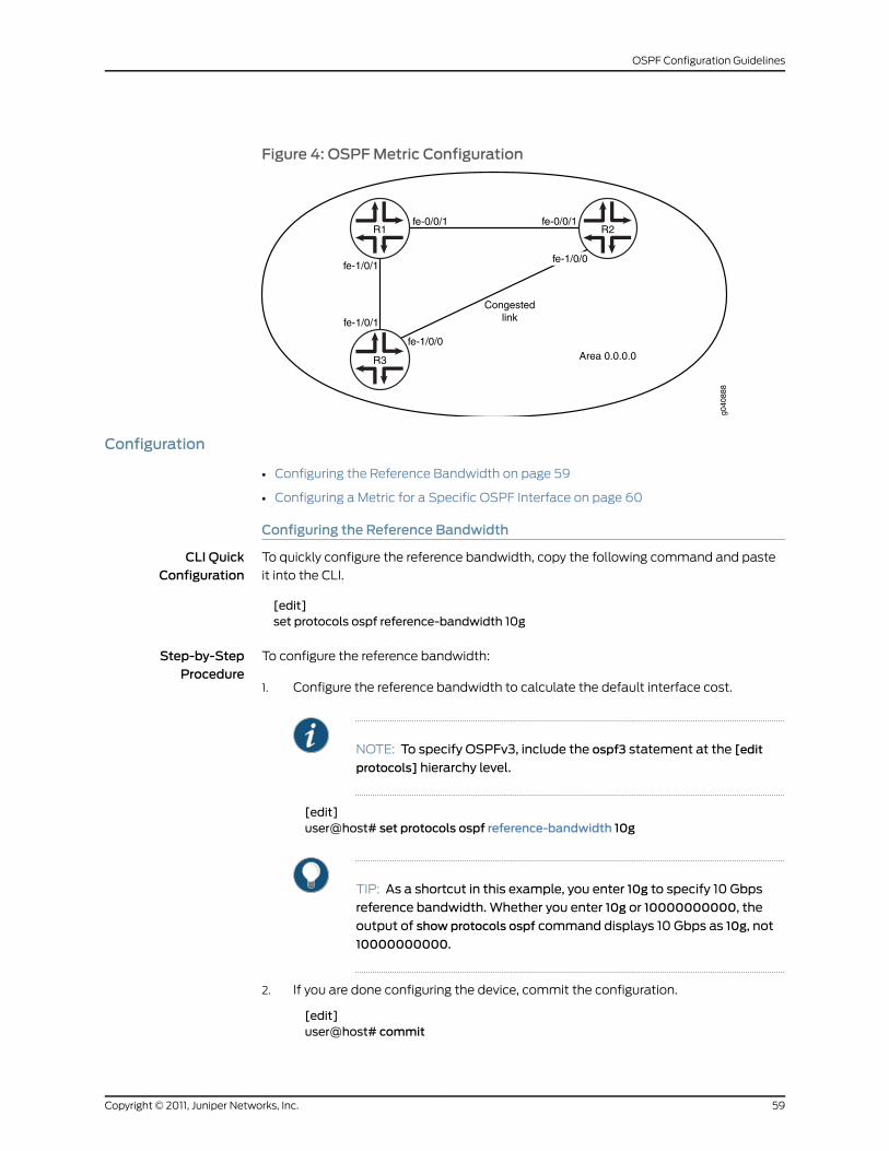
Figure 4: OSPFMetric Configuration
g040
888
R1
R3
fe-1/0/1
fe-1/0/1
fe-1/0/0
fe-0/0/1fe-0/0/1
fe-1/0/0
R2
Area 0.0.0.0
Congestedlink
Configuration
• Configuring the Reference Bandwidth on page 59
• Configuring a Metric for a Specific OSPF Interface on page 60
Configuring the Reference Bandwidth
CLI QuickConfiguration
To quickly configure the reference bandwidth, copy the following command and paste
it into the CLI.
[edit]set protocols ospf reference-bandwidth 10g
Step-by-StepProcedure
To configure the reference bandwidth:
Configure the reference bandwidth to calculate the default interface cost.1.
NOTE: To specify OSPFv3, include the ospf3 statement at the [edit
protocols] hierarchy level.
[edit]user@host# set protocols ospf reference-bandwidth 10g
TIP: As a shortcut in this example, you enter 10g to specify 10 Gbps
reference bandwidth. Whether you enter 10g or 10000000000, the
output of show protocols ospf command displays 10 Gbps as 10g, not
10000000000.
2. If you are done configuring the device, commit the configuration.
[edit]user@host# commit
59Copyright © 2011, Juniper Networks, Inc.
OSPF Configuration Guidelines
NOTE: Repeat thisentireconfigurationonall routingdevices inasharednetwork.
Results Confirm your configuration by entering the show protocols ospf command. If the output
does not display the intended configuration, repeat the instructions in this example to
correct the configuration.
user@host# show protocols ospfreference-bandwidth 10g;
To confirm your OSPFv3 configuration, enter the show protocols ospf3 command.
Configuring aMetric for a Specific OSPF Interface
CLI QuickConfiguration
To quickly configure a metric for a specific OSPF interface, copy the following command
and paste it into the CLI.
[edit]set protocols ospf area 0.0.0.0 interface fe-1/0/1 metric 5
Step-by-StepProcedure
To configure the metric for a specific OSPF interface:
Create an OSPF area.1.
NOTE: To specify OSPFv3, include the ospf3 statement at the [edit
protocols] hierarchy level.
[edit]user@host# edit protocols ospf area 0.0.0.0
2. Configure the metric of the OSPF network segment.
[edit protocols ospf area 0.0.0.0 ]user@host# set interface fe-1/0/1 metric 5
3. If you are done configuring the device, commit the configuration.
[edit protocols ospf area 0.0.0.0 ]user@host# commit
Results Confirm your configuration by entering the show protocols ospf command. If the output
does not display the intended configuration, repeat the instructions in this example to
correct the configuration.
user@host# show protocols ospfarea 0.0.0.0 {interface fe-1/0/1.0 {metric 5;
}
Copyright © 2011, Juniper Networks, Inc.60
Junos OS OSPF Configuration Guide
}
To confirm your OSPFv3 configuration, enter the show protocols ospf3 command.
Verification
Confirm that the configuration is working properly.
• Verifying the Configured Metric on page 61
• Verifying the Route on page 61
Verifying the ConfiguredMetric
Purpose Verify the metric setting on the interface. Confirm that the Cost field displays the
interface’s configured metric (cost). When choosing paths to a destination, OSPF uses
the path with the lowest cost.
Action From operational mode, enter the show ospf interface detail command for OSPFv2, and
enter the show ospf3 interface detail command for OSPFv3.
Verifying the Route
Purpose When choosing paths to a destination, OSPF uses the path with the lowest total cost.
Confirm that OSPF is using the appropriate path.
Action From operational mode, enter the show route command.
RelatedDocumentation
Understanding OSPF Traffic Control•
• Example: Controlling OSPF Route Preferences on page 63
Example: Dynamically Adjusting OSPF InterfaceMetrics Based on Bandwidth
This example shows how to dynamically adjust OSPF interface metrics based on
bandwidth.
• Requirements on page 61
• Overview on page 62
• Configuration on page 62
• Verification on page 63
Requirements
Before you begin:
• Configure the device interfaces. See the JunosOSNetwork InterfacesConfigurationGuide.
• Configure the router identifiers for the devices in your OSPF network. See Example:
Configuring an OSPF Router Identifier.
61Copyright © 2011, Juniper Networks, Inc.
OSPF Configuration Guidelines
• Control OSPF designated router election. See “Example: Controlling OSPF Designated
Router Election” on page 50
• Configure a single-area OSPF network. See Example: Configuring a Single-Area OSPF
Network.
Overview
You can specify a set of bandwidth threshold values and associated metric values for
an OSPF interface. When the bandwidth of an interface changes, the Junos OS
automatically sets the interface metric to the value associated with the appropriate
bandwidth threshold value. When you configure bandwidth-based metric values, you
typically configure multiple bandwidth and metric values.
In this example, you configure OSPF interface ae0 for bandwidth-based metrics by
including the bandwidth-based-metrics statement and the following settings:
• bandwidth—Specifies the bandwidth threshold in bits per second. The range is 9600
through 1,000,000,000,000,000.
• metric—Specifies the metric value to associate with a specific bandwidth value. The
range is 1 through 65,535.
Configuration
CLI QuickConfiguration
To quickly configure bandwidth threshold values and associated metric values for an
OSPF interface, copy the following commands, remove any line breaks, and then paste
the commands into the CLI.
[edit]set protocols ospf area 0.0.0.0 interface ae0.0metric 5set protocols ospf area 0.0.0.0 interface ae0.0 bandwidth-based-metrics bandwidth 1gmetric 60
set protocols ospf area 0.0.0.0 interface ae0.0 bandwidth-based-metrics bandwidth 10gmetric 50
To configure the metric for a specific OSPF interface:
1. Create an OSPF area.
NOTE: To specify OSPFv3, include the ospf3 statement at the [edit
protocols] hierarchy level.
[edit]user@host# edit protocols ospf area 0.0.0.0
2. Configure the metric of the OSPF network segment.
[edit protocols ospf area 0.0.0.0 ]user@host# set interface ae0metric 5
3. Configure the bandwidth threshold values and associated metric values.
[edit protocols ospf area 0.0.0.0 ]
Copyright © 2011, Juniper Networks, Inc.62
Junos OS OSPF Configuration Guide
user@host# set interface ae0.0 bandwidth-based-metrics bandwidth 1gmetric 60user@host# set interface ae0.0 bandwidth-based-metrics bandwidth 10gmetric 50
4. If you are done configuring the device, commit the configuration.
[edit protocols ospf area 0.0.0.0 ]user@host# commit
Results Confirm your configuration by entering the show protocols ospf command. If the output
does not display the intended configuration, repeat the instructions in this example to
correct the configuration.
user@host# show protocols ospfarea 0.0.0.0 {interface ae0.0 {bandwidth-based-metrics {bandwidth 1gmetric 60;bandwidth 10gmetric 50;
}metric 5;
}}
To confirm your OSPFv3 configuration, enter the show protocols ospf3 command.
Verification
Confirm that the configuration is working properly.
Verifying the ConfiguredMetric
Purpose Verify the metric setting on the interface. Confirm that the Cost field displays the
interface’s configured metric (cost). When choosing paths to a destination, OSPF uses
the path with the lowest cost.
Action From operational mode, enter the show ospf interface detail command for OSPFv2, and
enter the show ospf3 interface detail command for OSPFv3.
RelatedDocumentation
Understanding OSPF Traffic Control•
• Example: Controlling the Cost of Individual OSPF Network Segments on page 57
• Example: Controlling OSPF Route Preferences on page 63
Example: Controlling OSPF Route Preferences
This example shows how to control OSPF route selection in the forwarding table. This
example also shows how you might control route selection if you are migrating from
OSPF to another IGP.
• Requirements on page 64
• Overview on page 64
63Copyright © 2011, Juniper Networks, Inc.
OSPF Configuration Guidelines
• Configuration on page 64
• Verification on page 65
Requirements
This example assumes that OSPF is properly configured and running in your network,
and you want to control route selection because you are planning to migrate from OSPF
to a different IGP.
• Configure the device interfaces. See the JunosOSNetwork InterfacesConfigurationGuide.
• Configure the IGP that you want to migrate to. See the Junos OS Routing Protocols
Configuration Guide.
Overview
Route preferences are used to select which route is installed in the forwarding table when
several protocols calculate routes to the same destination. The route with the lowest
preference value is selected.
By default, internal OSPF routes have a preference value of 10, and external OSPF routes
have a preference value of 150. You might want to modify this setting if you are planning
to migrate from OSPF to a different IGP. Modifying the route preferences enables you to
perform the migration in a controlled manner.
This example makes the following assumptions:
• OSPF is already running in your network.
• You want to migrate from OSPF to IS-IS.
• You configured IS-IS per your network requirements and confirmed it is working properly.
In this example, you increase the OSPF route preference values to make them less
preferred than IS-IS routes by specifying 168 for internal OSPF routes and 169 for external
OSPF routes. IS-IS internal routes have a preference of either 15 (for Level1) or 18 (for
Level 2), and external routes have a preference of 160 (for Level 1) or 165 (for Level 2).
In general, it is preferred to leave the new protocol at its default settings to minimize
complexities and simplify any future addition of routing devices to the network. To modify
the OSPF route preference values, configure the following settings:
• preference—Specifies the route preference for internal OSPF routes. By default, internal
OSPF routes have a value of 10. The range is from 0 through 4,294967,295 (232
– 1).
• external-preference—Specifies the route preference for external OSPF routes. By default,
external OSPF routes have a value of 150. The range is from 0 through 4,294967,295
(232
– 1).
Configuration
CLI QuickConfiguration
To quickly configure the OSPF route preference values, copy the following command
and paste it into the CLI.
Copyright © 2011, Juniper Networks, Inc.64
Junos OS OSPF Configuration Guide
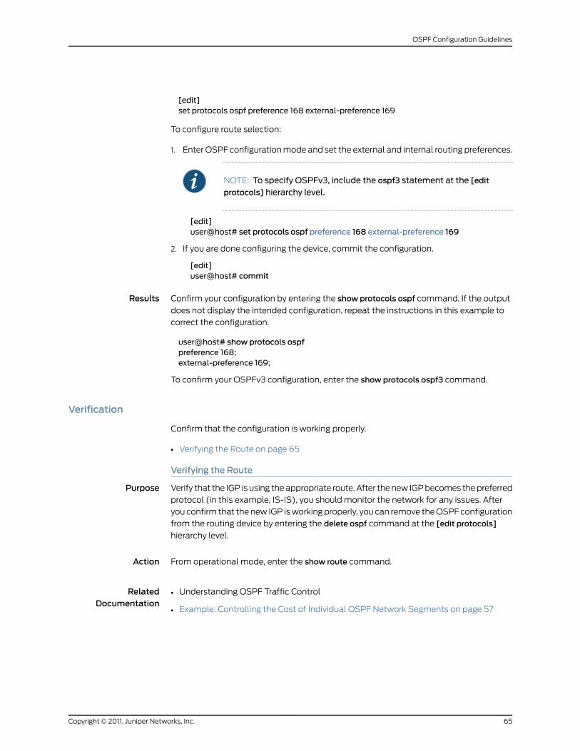
[edit]set protocols ospf preference 168 external-preference 169
To configure route selection:
1. Enter OSPF configuration mode and set the external and internal routing preferences.
NOTE: To specify OSPFv3, include the ospf3 statement at the [edit
protocols] hierarchy level.
[edit]user@host# set protocols ospf preference 168 external-preference 169
2. If you are done configuring the device, commit the configuration.
[edit]user@host# commit
Results Confirm your configuration by entering the show protocols ospf command. If the output
does not display the intended configuration, repeat the instructions in this example to
correct the configuration.
user@host# show protocols ospfpreference 168;external-preference 169;
To confirm your OSPFv3 configuration, enter the show protocols ospf3 command.
Verification
Confirm that the configuration is working properly.
• Verifying the Route on page 65
Verifying the Route
Purpose Verify that the IGP is using the appropriate route. After the new IGP becomes the preferred
protocol (in this example, IS-IS), you should monitor the network for any issues. After
you confirm that the new IGP is working properly, you can remove the OSPF configuration
from the routing device by entering the delete ospf command at the [edit protocols]
hierarchy level.
Action From operational mode, enter the show route command.
RelatedDocumentation
Understanding OSPF Traffic Control•
• Example: Controlling the Cost of Individual OSPF Network Segments on page 57
65Copyright © 2011, Juniper Networks, Inc.
OSPF Configuration Guidelines
Example: Configuring OSPF Timers
This example shows how to configure the OSPF timers.
• Requirements on page 66
• Overview on page 66
• Configuration on page 67
• Verification on page 71
Requirements
Before you begin:
• Configure the device interfaces. See the JunosOSNetwork InterfacesConfigurationGuide.
• Configure the router identifiers for the devices in your OSPF network. See Example:
Configuring an OSPF Router Identifier.
• Control OSPF designated router election. See “Example: Controlling OSPF Designated
Router Election” on page 50
• Configure a single-area OSPF network. See Example: Configuring a Single-Area OSPF
Network.
• Configure a multiarea OSPF network. See Example: Configuring a Multiarea OSPF
Network.
Overview
The default OSPF timer settings are optimal for most networks. However, depending on
your network requirements, you might need to modify the timer settings. This example
explains why you might need to modify the following timers:
• Hello interval
• Dead interval
• LSA retransmission interval
• Transit delay
Hello Interval and Dead Interval
The hello interval and the dead interval optimize convergence times by efficiently tracking
neighbor status. By lowering the values of the hello interval and the dead interval, you
can increase the convergence of OSPF routes if a path fails. These intervals must be the
same on all routing devices on a shared network. Otherwise, OSPF cannot establish the
appropriate adjacencies.
Copyright © 2011, Juniper Networks, Inc.66
Junos OS OSPF Configuration Guide
In the first example, you lower the hello interval to 2 seconds and the dead interval to 8
seconds on point-to-point OSPF interfaces fe-0/0/1 and fe-1/0/1 in area 0.0.0.0 by
configuring the following settings:
• hello-interval—Specifies the length of time, in seconds, before the routing device sends
a hello packet out of an interface. By default, the routing device sends hello packets
every 10 seconds. The range is from 1 through 255 seconds.
• dead-interval—Specifies the length of time, in seconds, that the routing device waits
before declaring that a neighboring routing device is unavailable. This is an interval
during which the routing device receives no hello packets from the neighbor. By default,
the routing device waits 40 seconds (four times the hello interval). The range is 1
through 65,535 seconds.
LSA Retransmission Interval
The link-state advertisement (LSA) retransmission interval optimizes the sending and
receiving of LSA and acknowledgement packets. You must configure the LSA
retransmission interval to be equal to or greater than 3 seconds to avoid triggering a
retransmit trap because the Junos OS delays LSA acknowledgments by up to 2 seconds.
If you have a virtual link, you might find increased performance by increasing the value
of the LSA retransmission interval.
In the second example, you increase the LSA retransmission timer to 8 seconds on OSPF
interface fe-0/0/1 in area 0.0.0.1 by configuring the following setting:
• retransmit-interval—Specifies the length of time, in seconds, that the routing device
waits to receive an LSA packet before retransmitting LSA to an interface’s neighbors.
By default, the routing device retransmits LSAs to its neighbors every 5 seconds. The
range is from 1 through 65,535 seconds.
Transit Delay
The transit delay sets the time the routing device uses to age a link-state update packet.
If you have a slow link (for example, one with an average propagation delay of multiple
seconds), you should increase the age of the packet by a similar amount. Doing this
ensures that you do not receive a packet back that is younger than the original copy.
In the final example, you increase the transit delay to 2 seconds on OSPF interface fe-1/0/1
in area 0.0.0.1. By configuring the following setting, this causes the routing device to age
the link-state update packet by 2 seconds:
• transit-delay—Sets the estimated time required to transmit a link-state update on the
interface. You should never have to modify the transit delay time. By default, the routing
device ages the packet by 1 second. The range is from 1 through 65,535 seconds.
Configuration
• Configuring the Hello Interval and the Dead Interval on page 68
• Controlling the LSA Retransmission Interval on page 69
• Specifying the Transit Delay on page 70
67Copyright © 2011, Juniper Networks, Inc.
OSPF Configuration Guidelines
Configuring the Hello Interval and the Dead Interval
CLI QuickConfiguration
To quickly configure the hello and dead intervals, copy the following commands and
paste them into the CLI.
[edit]set protocols ospf area 0.0.0.0 interface fe-0/0/1 hello-interval 2set protocols ospf area 0.0.0.0 interface fe-0/0/1 dead-interval 8set protocols ospf area 0.0.0.0 interface fe-1/0/1 hello-interval 2set protocols ospf area 0.0.0.0 interface fe-1/0/1 dead-interval 8
Step-by-StepProcedure
To configure the hello and dead intervals:
Create an OSPF area.1.
NOTE: To specify OSPFv3, include the ospf3 statement at the [edit
protocols] hierarchy level.
[edit]user@host# edit protocols ospf area 0.0.0.0
2. Specify the interfaces.
[edit protocols ospf area 0.0.0.0]user@host# set interface fe-0/0/1user@host# set interface fe-1/0/1
3. Configure the hello interval.
[edit protocols ospf area 0.0.0.0 ]user@host# set interface fe-0/0/1 hello-interval 2user@host# set interface fe-1/0/1 hello-interval 2
4. Configure the dead interval.
[edit protocols ospf area 0.0.0.0 ]user@host# set interface fe-0/0/1 dead-interval 8user@host# set interface fe-1/0/1 dead-interval 8
5. If you are done configuring the device, commit the configuration.
[edit protocols ospf area 0.0.0.0 ]user@host# commit
NOTE: Repeat thisentireconfigurationonall routingdevices inasharednetwork.
Results Confirm your configuration by entering the show protocols ospf command. If the output
does not display the intended configuration, repeat the instructions in this example to
correct the configuration.
Copyright © 2011, Juniper Networks, Inc.68
Junos OS OSPF Configuration Guide
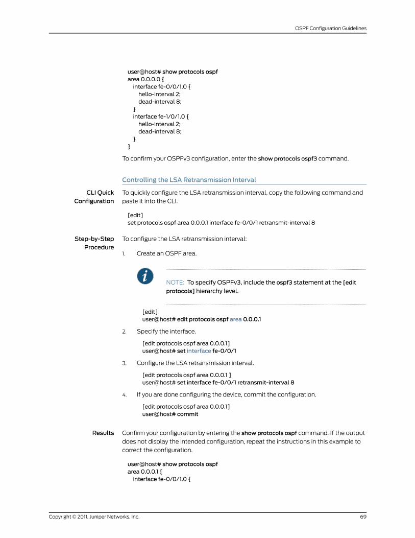
user@host# show protocols ospfarea 0.0.0.0 {interface fe-0/0/1.0 {hello-interval 2;dead-interval 8;
}interface fe-1/0/1.0 {hello-interval 2;dead-interval 8;
}}
To confirm your OSPFv3 configuration, enter the show protocols ospf3 command.
Controlling the LSA Retransmission Interval
CLI QuickConfiguration
To quickly configure the LSA retransmission interval, copy the following command and
paste it into the CLI.
[edit]set protocols ospf area 0.0.0.1 interface fe-0/0/1 retransmit-interval 8
Step-by-StepProcedure
To configure the LSA retransmission interval:
Create an OSPF area.1.
NOTE: To specify OSPFv3, include the ospf3 statement at the [edit
protocols] hierarchy level.
[edit]user@host# edit protocols ospf area 0.0.0.1
2. Specify the interface.
[edit protocols ospf area 0.0.0.1]user@host# set interface fe-0/0/1
3. Configure the LSA retransmission interval.
[edit protocols ospf area 0.0.0.1 ]user@host# set interface fe-0/0/1 retransmit-interval 8
4. If you are done configuring the device, commit the configuration.
[edit protocols ospf area 0.0.0.1]user@host# commit
Results Confirm your configuration by entering the show protocols ospf command. If the output
does not display the intended configuration, repeat the instructions in this example to
correct the configuration.
user@host# show protocols ospfarea 0.0.0.1 {interface fe-0/0/1.0 {
69Copyright © 2011, Juniper Networks, Inc.
OSPF Configuration Guidelines
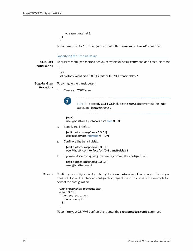
retransmit-interval 8;}
}
To confirm your OSPFv3 configuration, enter the show protocols ospf3 command.
Specifying the Transit Delay
CLI QuickConfiguration
To quickly configure the transit delay, copy the following command and paste it into the
CLI.
[edit]set protocols ospf area 0.0.0.1 interface fe-1/0/1 transit-delay 2
Step-by-StepProcedure
To configure the transit delay:
Create an OSPF area.1.
NOTE: To specify OSPFv3, include the ospf3 statement at the [edit
protocols] hierarchy level.
[edit]user@host# edit protocols ospf area 0.0.0.1
2. Specify the interface.
[edit protocols ospf area 0.0.0.1]user@host# set interface fe-1/0/1
3. Configure the transit delay.
[edit protocols ospf area 0.0.0.1 ]user@host# set interface fe-1/0/1 transit-delay 2
4. If you are done configuring the device, commit the configuration.
[edit protocols ospf area 0.0.0.1 ]user@host# commit
Results Confirm your configuration by entering the show protocols ospf command. If the output
does not display the intended configuration, repeat the instructions in this example to
correct the configuration.
user@host# show protocols ospfarea 0.0.0.1 {interface fe-1/0/1.0 {transit-delay 2;
}}
To confirm your OSPFv3 configuration, enter the show protocols ospf3 command.
Copyright © 2011, Juniper Networks, Inc.70
Junos OS OSPF Configuration Guide
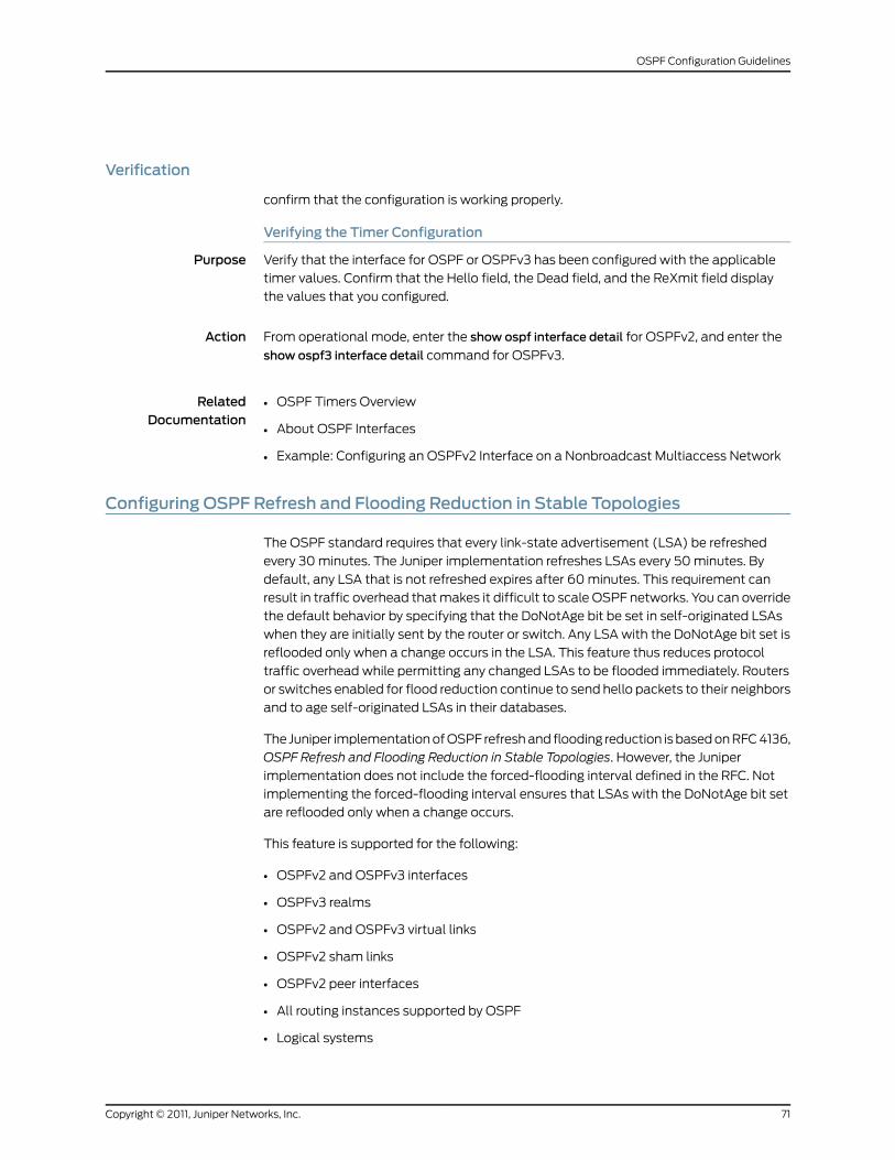
Verification
confirm that the configuration is working properly.
Verifying the Timer Configuration
Purpose Verify that the interface for OSPF or OSPFv3 has been configured with the applicable
timer values. Confirm that the Hello field, the Dead field, and the ReXmit field display
the values that you configured.
Action From operational mode, enter the show ospf interface detail for OSPFv2, and enter the
show ospf3 interface detail command for OSPFv3.
RelatedDocumentation
OSPF Timers Overview•
• About OSPF Interfaces
• Example: Configuring an OSPFv2 Interface on a Nonbroadcast Multiaccess Network
Configuring OSPF Refresh and Flooding Reduction in Stable Topologies
The OSPF standard requires that every link-state advertisement (LSA) be refreshed
every 30 minutes. The Juniper implementation refreshes LSAs every 50 minutes. By
default, any LSA that is not refreshed expires after 60 minutes. This requirement can
result in traffic overhead that makes it difficult to scale OSPF networks. You can override
the default behavior by specifying that the DoNotAge bit be set in self-originated LSAs
when they are initially sent by the router or switch. Any LSA with the DoNotAge bit set is
reflooded only when a change occurs in the LSA. This feature thus reduces protocol
traffic overhead while permitting any changed LSAs to be flooded immediately. Routers
or switches enabled for flood reduction continue to send hello packets to their neighbors
and to age self-originated LSAs in their databases.
The Juniper implementation of OSPF refresh and flooding reduction is based on RFC 4136,
OSPF Refresh and Flooding Reduction in Stable Topologies. However, the Juniper
implementation does not include the forced-flooding interval defined in the RFC. Not
implementing the forced-flooding interval ensures that LSAs with the DoNotAge bit set
are reflooded only when a change occurs.
This feature is supported for the following:
• OSPFv2 and OSPFv3 interfaces
• OSPFv3 realms
• OSPFv2 and OSPFv3 virtual links
• OSPFv2 sham links
• OSPFv2 peer interfaces
• All routing instances supported by OSPF
• Logical systems
71Copyright © 2011, Juniper Networks, Inc.
OSPF Configuration Guidelines
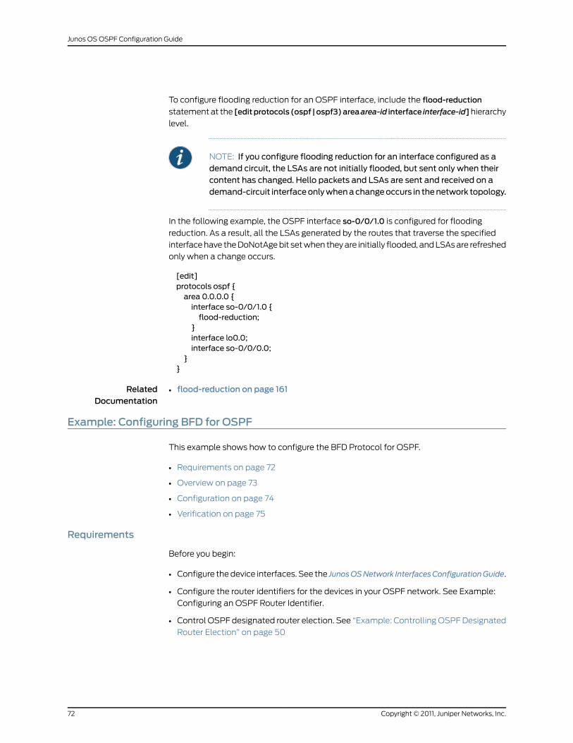
To configure flooding reduction for an OSPF interface, include the flood-reduction
statement at the [editprotocols (ospf |ospf3)areaarea-id interface interface-id]hierarchy
level.
NOTE: If you configure flooding reduction for an interface configured as ademand circuit, the LSAs are not initially flooded, but sent only when theircontent has changed. Hello packets and LSAs are sent and received on ademand-circuit interfaceonlywhenachangeoccurs in thenetwork topology.
In the following example, the OSPF interface so-0/0/1.0 is configured for flooding
reduction. As a result, all the LSAs generated by the routes that traverse the specified
interface have the DoNotAge bit set when they are initially flooded, and LSAs are refreshed
only when a change occurs.
[edit]protocols ospf {area 0.0.0.0 {interface so-0/0/1.0 {flood-reduction;
}interface lo0.0;interface so-0/0/0.0;
}}
RelatedDocumentation
flood-reduction on page 161•
Example: Configuring BFD for OSPF
This example shows how to configure the BFD Protocol for OSPF.
• Requirements on page 72
• Overview on page 73
• Configuration on page 74
• Verification on page 75
Requirements
Before you begin:
• Configure the device interfaces. See the JunosOSNetwork InterfacesConfigurationGuide.
• Configure the router identifiers for the devices in your OSPF network. See Example:
Configuring an OSPF Router Identifier.
• Control OSPF designated router election. See “Example: Controlling OSPF Designated
Router Election” on page 50
Copyright © 2011, Juniper Networks, Inc.72
Junos OS OSPF Configuration Guide
• Configure a single-area OSPF network. See Example: Configuring a Single-Area OSPF
Network.
• Configure a multiarea OSPF network. See Example: Configuring a Multiarea OSPF
Network.
Overview
An alternative to adjusting the OSPF hello interval and dead interval settings to increase
route convergence is to configure BFD. The BFD Protocol is a simple hello mechanism
that detects failures in a network. The BFD failure detection timers have shorter timer
limits than the OSPF failure detection mechanisms, thereby providing faster detection.
BFD is useful on interfaces that are unable to detect failure quickly, such as Ethernet
interfaces. Other interfaces, such as SONET interfaces, already have built-in failure
detection. Configuring BFD on those interfaces is unnecessary.
You configure BFD on a pair of neighboring OSPF interfaces. Unlike the OSPF hello interval
and dead interval settings, you do not have to enable BFD on all interfaces in an OSPF
area.
In this example, you enable failure detection by including the bfd-liveness-detection
statement on the neighbor OSPF interface fe-0/1/0 in area 0.0.0.0 and configure the
BFD packet exchange interval to 300 milliseconds, configure 4 as the number of missed
hello packets that causes the originating interface to be declared down, and configure
BFD sessions only for OSPF neighbors with full neighbor adjacency by including the
following settings:
• full-neighbors-only—In Junos OS Release 9.5 and later, configures the BFD Protocol
to establish BFD sessions only for OSPF neighbors with full neighbor adjacency. The
default behavior is to establish BFD sessions for all OSPF neighbors.
• minimum-interval—Configures the minimum interval, in milliseconds, at which the local
routing device transmits hello packets as well as the minimum interval at which the
routing device expects to receive a reply from the neighbor with which it has established
a BFD session. You can configure a number in the range from 1 through 255,000
milliseconds. You can also specify the minimum transmit and receive intervals
separately.
73Copyright © 2011, Juniper Networks, Inc.
OSPF Configuration Guidelines
NOTE: BFD is an intensive protocol that consumes system resources.Specifying aminimum interval for BFD less than 100ms for RoutingEngine-based sessions and 10ms for distributed BFD sessions can causeundesired BFD flapping.
Depending on your network environment, these additionalrecommendationsmight apply:
• For large-scale network deployments with a large number of BFDsessions, specifyaminimumintervalof300msforRoutingEngine-basedsessions and 100ms for distributed BFD sessions.
• For very large-scale network deployments with a large number of BFDsessions, contact Juniper Networks customer support for moreinformation.
• For BFD sessions to remain up during a Routing Engine switchover eventwhen nonstop active routing (NSR) is configured, specify aminimuminterval of 2500ms for Routing Engine-based sessions. For distributedBFD sessions with NSR configured, theminimum intervalrecommendations are unchanged and depend only on your networkdeployment.
• multiplier—Configures the number of hello packets not received by a neighbor that
causes the originating interface to be declared down. By default, three missed hello
packets cause the originating interface to be declared down. You can configure a value
in the range from 1 through 255.
Configuration
CLI QuickConfiguration
To quickly configure the BFD protocol for OSPF, copy the following commands, remove
any line breaks, and then paste the commands into the CLI.
[edit]setprotocolsospfarea0.0.0.0 interface fe-0/0/1bfd-liveness-detectionminimum-interval300
set protocols ospf area 0.0.0.0 interface fe-0/0/1 bfd-liveness-detectionmultiplier 4setprotocolsospfarea0.0.0.0 interfacefe-0/0/1bfd-liveness-detectionfull-neighbors-only
Step-by-StepProcedure
To configure the BFD protocol for OSPF on one neighboring interface:
Create an OSPF area.1.
NOTE: To specify OSPFv3, include the ospf3 statement at the [edit
protocols] hierarchy level.
[edit]user@host# edit protocols ospf area 0.0.0.0
Copyright © 2011, Juniper Networks, Inc.74
Junos OS OSPF Configuration Guide
2. Specify the interface.
[edit protocols ospf area 0.0.0.0]user@host# set interface fe-0/0/1
3. Specify the minimum transmit and receive intervals.
[edit protocols ospf area 0.0.0.0 ]user@host# set interface fe-0/0/1 bfd-liveness-detectionminimum-interval 300
4. Configure the number of missed hello packets that cause the originating interface
to be declared down.
[edit protocols ospf area 0.0.0.0 ]user@host# set interface fe-0/0/1 bfd-liveness-detectionmultiplier 4
5. Configure BFD sessions only for OSPF neighbors with full neighbor adjacency.
[edit protocols ospf area 0.0.0.0 ]user@host# set interface fe-0/0/1 bfd-liveness-detection full-neighbors-only
6. If you are done configuring the device, commit the configuration.
[edit protocols ospf area 0.0.0.0 ]user@host# commit
NOTE: Repeat this entire configuration on the other neighboringinterface.
Results Confirm your configuration by entering the show protocols ospf command. If the output
does not display the intended configuration, repeat the instructions in this example to
correct the configuration.
user@host# show protocols ospfarea 0.0.0.0 {interface fe-0/0/1.0 {bfd-liveness-detection {minimum-interval 300;multiplier 4;full-neighbors-only;
}}
}
To confirm your OSPFv3 configuration, enter the show protocols ospf3 command.
Verification
Confirm that the configuration is working properly.
75Copyright © 2011, Juniper Networks, Inc.
OSPF Configuration Guidelines
Verifying the BFD Sessions
Purpose Verify that the OSPF interfaces have active BFD sessions.
• The Address field displays the IP address of the neighbor.
• The Interface field displays the interface you configured for BFD.
• The State field displays the state of the neighbor and should show Full to reflect the
full neighbor adjacency that you configured.
• The Transmit Interval field displays the time interval you configured to send BFD
packets.
• The Multiplier field displays the multiplier you configured.
Action From operational mode, enter the show bfd session detail command.
RelatedDocumentation
BFD for OSPF Overview•
• BFD Authentication for OSPF Overview on page 17
• BFD Authentication for OSPF Overview on page 17
• Configuring BFD Authentication for OSPF on page 76
Configuring BFD Authentication for OSPF
Beginning with Junos OS Release 9.6, you can configure authentication for BFD sessions
running over OSPFv2. Routing instances are also supported.
The following sections provide instructions for configuring and viewing BFD authentication
on OSPF:
• Configuring BFD Authentication Parameters on page 76
• Viewing Authentication Information for BFD Sessions on page 78
Configuring BFD Authentication Parameters
Only three steps are needed to configure authentication on a BFD session:
1. Specify the BFD authentication algorithm for the OSPFv2 protocol.
2. Associate the authentication keychain with the OSPFv2 protocol.
3. Configure the related security authentication keychain.
To configure BFD authentication:
1. Specify the algorithm (keyed-md5, keyed-sha-1, meticulous-keyed-md5,
meticulous-keyed-sha-1, or simple-password) to use for BFD authentication on an
OSPF route or routing instance.
[edit]
Copyright © 2011, Juniper Networks, Inc.76
Junos OS OSPF Configuration Guide
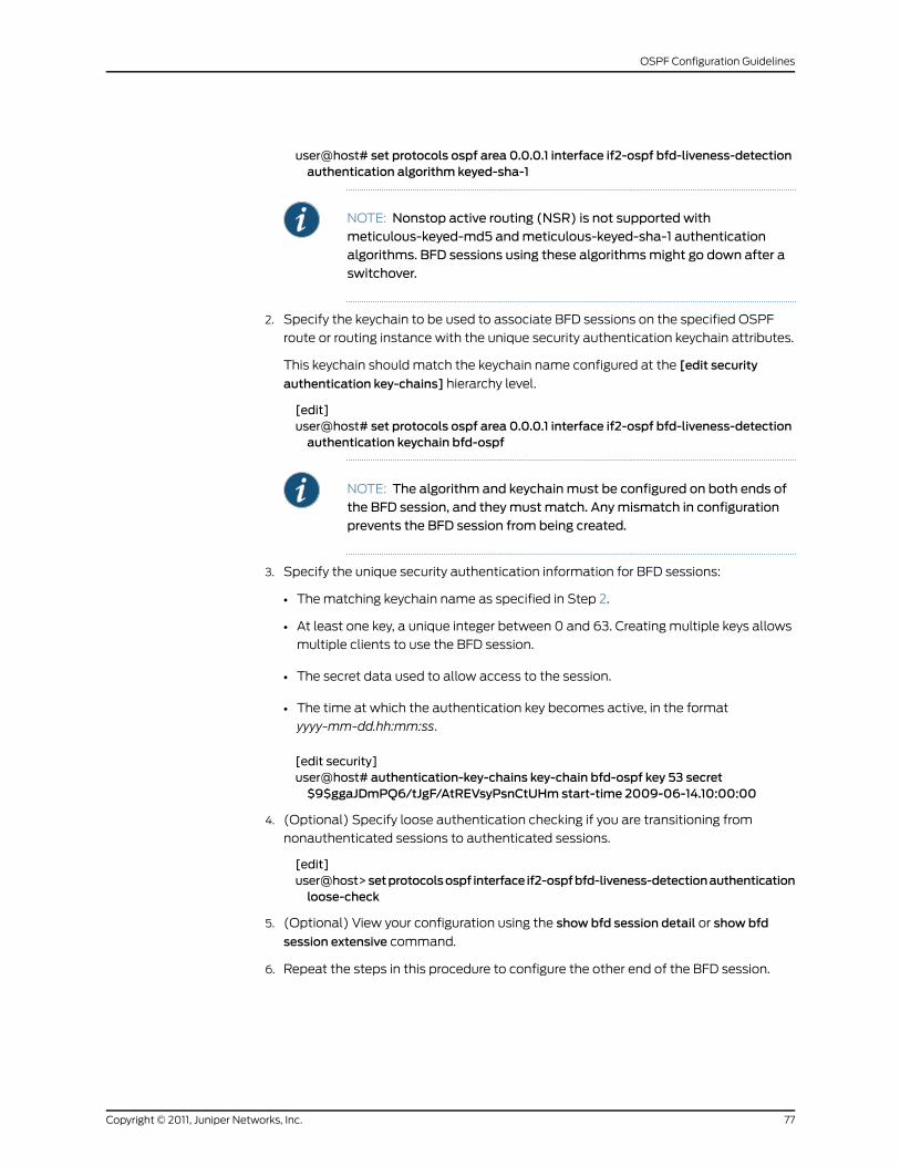
user@host# set protocols ospf area 0.0.0.1 interface if2-ospf bfd-liveness-detectionauthentication algorithm keyed-sha-1
NOTE: Nonstop active routing (NSR) is not supported withmeticulous-keyed-md5 andmeticulous-keyed-sha-1 authenticationalgorithms. BFD sessions using these algorithmsmight go down after aswitchover.
2. Specify the keychain to be used to associate BFD sessions on the specified OSPF
route or routing instance with the unique security authentication keychain attributes.
This keychain should match the keychain name configured at the [edit security
authentication key-chains] hierarchy level.
[edit]user@host# set protocols ospf area 0.0.0.1 interface if2-ospf bfd-liveness-detectionauthentication keychain bfd-ospf
NOTE: The algorithm and keychainmust be configured on both ends ofthe BFD session, and theymust match. Anymismatch in configurationprevents the BFD session from being created.
3. Specify the unique security authentication information for BFD sessions:
• The matching keychain name as specified in Step 2.
• At least one key, a unique integer between 0 and 63. Creating multiple keys allows
multiple clients to use the BFD session.
• The secret data used to allow access to the session.
• The time at which the authentication key becomes active, in the format
yyyy-mm-dd.hh:mm:ss.
[edit security]user@host# authentication-key-chains key-chain bfd-ospf key 53 secret$9$ggaJDmPQ6/tJgF/AtREVsyPsnCtUHm start-time 2009-06-14.10:00:00
4. (Optional) Specify loose authentication checking if you are transitioning from
nonauthenticated sessions to authenticated sessions.
[edit]user@host>setprotocolsospf interface if2-ospfbfd-liveness-detectionauthenticationloose-check
5. (Optional) View your configuration using the show bfd session detail or show bfd
session extensive command.
6. Repeat the steps in this procedure to configure the other end of the BFD session.
77Copyright © 2011, Juniper Networks, Inc.
OSPF Configuration Guidelines
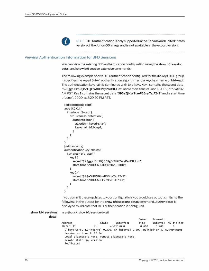
NOTE: BFDauthentication isonly supported in theCanadaandUnitedStatesversion of the Junos OS image and is not available in the export version.
Viewing Authentication Information for BFD Sessions
You can view the existing BFD authentication configuration using the show bfd session
detail and show bfd session extensive commands.
The following example shows BFD authentication configured for the if2-ospf BGP group.
It specifies the keyed SHA-1 authentication algorithm and a keychain name of bfd-ospf.
The authentication keychain is configured with two keys. Key 1 contains the secret data
“$9$ggaJDmPQ6/tJgF/AtREVsyPsnCtUHm” and a start time of June 1, 2009, at 9:46:02
AM PST. Key 2 contains the secret data “$9$a5jiKW9l.reP38ny.TszF2/9” and a start time
of June 1, 2009, at 3:29:20 PM PST.
[edit protocols ospf]area 0.0.0.1 {interface if2-ospf {bfd-liveness-detection {authentication {algorithm keyed-sha-1;key-chain bfd-ospf;
}}
}}[edit security]authentication key-chains {key-chain bfd-ospf {key 1 {secret “$9$ggaJDmPQ6/tJgF/AtREVsyPsnCtUHm”;start-time “2009-6-1.09:46:02 -0700”;
}key 2 {secret “$9$a5jiKW9l.reP38ny.TszF2/9”;start-time “2009-6-1.15:29:20 -0700”;
}}
}
If you commit these updates to your configuration, you would see output similar to the
following. In the output for the show bfd sessions detail command, Authenticate is
displayed to indicate that BFD authentication is configured.
show bfd sessionsdetail
user@host# show bfd session detail
Detect TransmitAddress State Interface Time Interval Multiplier10.9.1.33 Up so-7/1/0.0 0.600 0.200 3 Client OSPF, TX interval 0.200, RX interval 0.200, multiplier 3, Authenticate Session up time 3d 00:34 Local diagnostic None, remote diagnostic None Remote state Up, version 1 Replicated
Copyright © 2011, Juniper Networks, Inc.78
Junos OS OSPF Configuration Guide
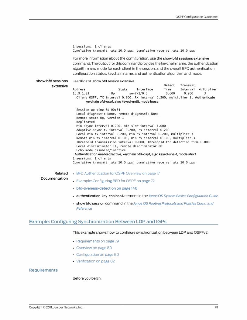
1 sessions, 1 clientsCumulative transmit rate 10.0 pps, cumulative receive rate 10.0 pps
For more information about the configuration, use the show bfd sessions extensive
command. The output for this command provides the keychain name, the authentication
algorithm and mode for each client in the session, and the overall BFD authentication
configuration status, keychain name, and authentication algorithm and mode.
show bfd sessionsextensive
user@host# show bfd session extensive Detect TransmitAddress State Interface Time Interval Multiplier10.9.1.33 Up so-7/1/0.0 0.600 0.200 3 Client OSPF, TX interval 0.200, RX interval 0.200, multiplier 3, Authenticate
keychain bfd-ospf, algo keyed-md5, mode loose
Session up time 3d 00:34 Local diagnostic None, remote diagnostic None Remote state Up, version 1 Replicated Min async interval 0.200, min slow interval 1.000 Adaptive async tx interval 0.200, rx interval 0.200 Local min tx interval 0.200, min rx interval 0.200, multiplier 3 Remote min tx interval 0.100, min rx interval 0.100, multiplier 3 Threshold transmission interval 0.000, Threshold for detection time 0.000 Local discriminator 11, remote discriminator 80 Echo mode disabled/inactiveAuthentication enabled/active, keychain bfd-ospf, algo keyed-sha-1, mode strict1 sessions, 1 clientsCumulative transmit rate 10.0 pps, cumulative receive rate 10.0 pps
RelatedDocumentation
BFD Authentication for OSPF Overview on page 17•
• Example: Configuring BFD for OSPF on page 72
• bfd-liveness-detection on page 146
• authentication-key-chains statement in the Junos OS System Basics Configuration Guide
• show bfd session command in the Junos OS Routing Protocols and Policies Command
Reference
Example: Configuring Synchronization Between LDP and IGPs
This example shows how to configure synchronization between LDP and OSPFv2.
• Requirements on page 79
• Overview on page 80
• Configuration on page 80
• Verification on page 82
Requirements
Before you begin:
79Copyright © 2011, Juniper Networks, Inc.
OSPF Configuration Guidelines
• Configure the device interfaces. See the JunosOSNetwork InterfacesConfigurationGuide.
• Configure the router identifiers for the devices in your OSPF network. See Example:
Configuring an OSPF Router Identifier.
• Control OSPF designated router election. See “Example: Controlling OSPF Designated
Router Election” on page 50
• Configure a single-area OSPF network. See Example: Configuring a Single-Area OSPF
Network.
• Configure a multiarea OSPF network. See Example: Configuring a Multiarea OSPF
Network.
Overview
In this example, configure synchronization between LDP and OSPFv2 by performing the
following tasks:
• Enable LDP on interface so-1/0/3, which is a member of OSPF area 0.0.0.0, by including
the ldp statement at the [edit protocols] hierarchy level. You can configure one or more
interfaces. By default, LDP is disabled on the routing device.
• Enable LDP synchronization by including the ldp-synchronization statement at the [edit
protocols ospf area area-id interface interface-name] hierarchy level. This statement
enables LDP synchronization by advertising the maximum cost metric until LDP is
operational on the link.
• Configure the amount of time (in seconds) the routing device advertises the maximum
cost metric for a link that is not fully operational by including the hold-time statement
at the [edit protocols ospf area area-id interface interface-name ldp-synchronization]
hierarchy level. If you do not configure the hold-time statement, the hold-time value
defaults to infinity. The range is from 1 through 65,535 seconds. In this example,
configure 10 seconds for the hold-time interval.
This example also shows how to disable synchronization between LDP and OSPFv2 by
including the disable statement at the [edit protocols ospf area area-id interface
interface-name ldp-synchronization] hierarchy level.
Configuration
• Enabling Synchronization Between LDP and OSPFv2 on page 80
• Disabling Synchronization Between LDP and OSPFv2 on page 81
Enabling Synchronization Between LDP andOSPFv2
CLI QuickConfiguration
The following example requires you to navigate various levels in the configuration
hierarchy. For information about navigating the CLI, see Modifying the Junos OS
Configuration in Junos OS CLI, Release 11.4.
To quickly enable synchronization between LDP and OSPFv2, copy the following
commands, remove any line breaks, and then paste them into the CLI.
[edit]
Copyright © 2011, Juniper Networks, Inc.80
Junos OS OSPF Configuration Guide
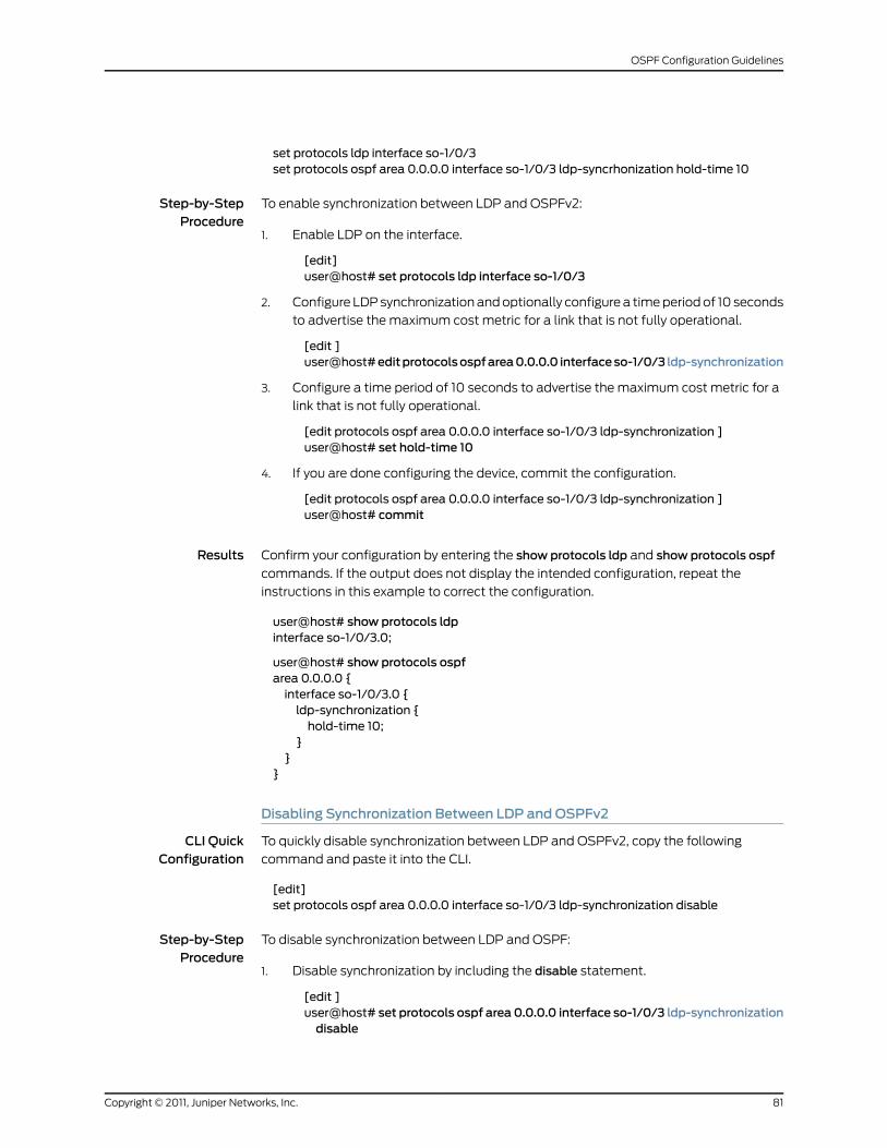
set protocols ldp interface so-1/0/3set protocols ospf area 0.0.0.0 interface so-1/0/3 ldp-syncrhonization hold-time 10
Step-by-StepProcedure
To enable synchronization between LDP and OSPFv2:
Enable LDP on the interface.1.
[edit]user@host# set protocols ldp interface so-1/0/3
2. Configure LDP synchronization and optionally configure a time period of 10 seconds
to advertise the maximum cost metric for a link that is not fully operational.
[edit ]user@host#editprotocolsospfarea0.0.0.0 interfaceso-1/0/3 ldp-synchronization
3. Configure a time period of 10 seconds to advertise the maximum cost metric for a
link that is not fully operational.
[edit protocols ospf area 0.0.0.0 interface so-1/0/3 ldp-synchronization ]user@host# set hold-time 10
4. If you are done configuring the device, commit the configuration.
[edit protocols ospf area 0.0.0.0 interface so-1/0/3 ldp-synchronization ]user@host# commit
Results Confirm your configuration by entering the show protocols ldp and show protocols ospf
commands. If the output does not display the intended configuration, repeat the
instructions in this example to correct the configuration.
user@host# show protocols ldpinterface so-1/0/3.0;
user@host# show protocols ospfarea 0.0.0.0 {interface so-1/0/3.0 {ldp-synchronization {hold-time 10;
}}
}
Disabling Synchronization Between LDP andOSPFv2
CLI QuickConfiguration
To quickly disable synchronization between LDP and OSPFv2, copy the following
command and paste it into the CLI.
[edit]set protocols ospf area 0.0.0.0 interface so-1/0/3 ldp-synchronization disable
Step-by-StepProcedure
To disable synchronization between LDP and OSPF:
Disable synchronization by including the disable statement.1.
[edit ]user@host# set protocols ospf area 0.0.0.0 interface so-1/0/3 ldp-synchronizationdisable
81Copyright © 2011, Juniper Networks, Inc.
OSPF Configuration Guidelines
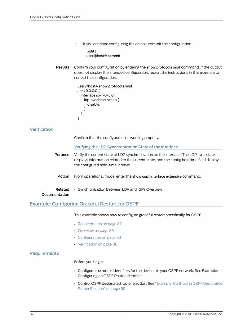
2. If you are done configuring the device, commit the configuration.
[edit]user@host# commit
Results Confirm your configuration by entering the show protocols ospf command. If the output
does not display the intended configuration, repeat the instructions in this example to
correct the configuration.
user@host# show protocols ospfarea 0.0.0.0 {interface so-1/0/3.0 {ldp-synchronization {disable;
}}
}
Verification
Confirm that the configuration is working properly.
Verifying the LDP Synchronization State of the Interface
Purpose Verify the current state of LDP synchronization on the interface. The LDP sync state
displays information related to the current state, and the config holdtime field displays
the configured hold-time interval.
Action From operational mode, enter the show ospf interface extensive command.
RelatedDocumentation
Synchronization Between LDP and IGPs Overview•
Example: Configuring Graceful Restart for OSPF
This example shows how to configure graceful restart specifically for OSPF.
• Requirements on page 82
• Overview on page 83
• Configuration on page 83
• Verification on page 86
Requirements
Before you begin:
• Configure the router identifiers for the devices in your OSPF network. See Example:
Configuring an OSPF Router Identifier.
• Control OSPF designated router election. See “Example: Controlling OSPF Designated
Router Election” on page 50
Copyright © 2011, Juniper Networks, Inc.82
Junos OS OSPF Configuration Guide
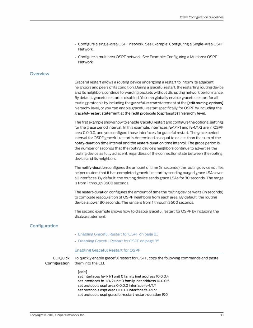
• Configure a single-area OSPF network. See Example: Configuring a Single-Area OSPF
Network.
• Configure a multiarea OSPF network. See Example: Configuring a Multiarea OSPF
Network.
Overview
Graceful restart allows a routing device undergoing a restart to inform its adjacent
neighbors and peers of its condition. During a graceful restart, the restarting routing device
and its neighbors continue forwarding packets without disrupting network performance.
By default, graceful restart is disabled. You can globally enable graceful restart for all
routing protocols by including the graceful-restart statement at the [edit routing-options]
hierarchy level, or you can enable graceful restart specifically for OSPF by including the
graceful-restart statement at the [edit protocols (ospf|ospf3)] hierarchy level.
The first example shows how to enable graceful restart and configure the optional settings
for the grace period interval. In this example, interfaces fe-1/1/1 and fe-1/1/2 are in OSPF
area 0.0.0.0, and you configure those interfaces for graceful restart. The grace period
interval for OSPF graceful restart is determined as equal to or less than the sum of the
notify-duration time interval and the restart-duration time interval. The grace period is
the number of seconds that the routing device’s neighbors continue to advertise the
routing device as fully adjacent, regardless of the connection state between the routing
device and its neighbors.
Thenotify-durationconfigures the amount of time (in seconds) the routing device notifies
helper routers that it has completed graceful restart by sending purged grace LSAs over
all interfaces. By default, the routing device sends grace LSAs for 30 seconds. The range
is from 1 through 3600 seconds.
The restart-duration configures the amount of time the routing device waits (in seconds)
to complete reacquisition of OSPF neighbors from each area. By default, the routing
device allows 180 seconds. The range is from 1 through 3600 seconds.
The second example shows how to disable graceful restart for OSPF by including the
disable statement.
Configuration
• Enabling Graceful Restart for OSPF on page 83
• Disabling Graceful Restart for OSPF on page 85
Enabling Graceful Restart for OSPF
CLI QuickConfiguration
To quickly enable graceful restart for OSPF, copy the following commands and paste
them into the CLI.
[edit]set interfaces fe-1/1/1 unit 0 family inet address 10.0.0.4set interfaces fe-1/1/2 unit 0 family inet address 10.0.0.5set protocols ospf area 0.0.0.0 interface fe-1/1/1set protocols ospf area 0.0.0.0 interface fe-1/1/2set protocols ospf graceful-restart restart-duration 190
83Copyright © 2011, Juniper Networks, Inc.
OSPF Configuration Guidelines
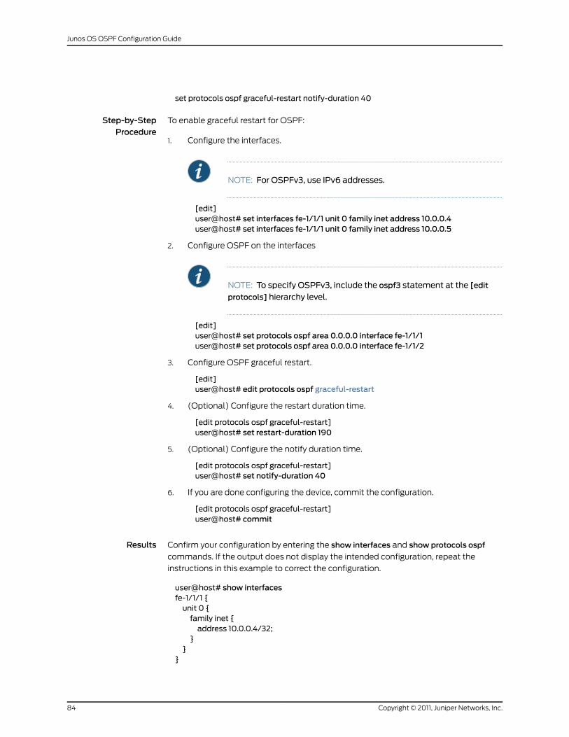
set protocols ospf graceful-restart notify-duration 40
Step-by-StepProcedure
To enable graceful restart for OSPF:
Configure the interfaces.1.
NOTE: For OSPFv3, use IPv6 addresses.
[edit]user@host# set interfaces fe-1/1/1 unit 0 family inet address 10.0.0.4user@host# set interfaces fe-1/1/1 unit 0 family inet address 10.0.0.5
2. Configure OSPF on the interfaces
NOTE: To specify OSPFv3, include the ospf3 statement at the [edit
protocols] hierarchy level.
[edit]user@host# set protocols ospf area 0.0.0.0 interface fe-1/1/1user@host# set protocols ospf area 0.0.0.0 interface fe-1/1/2
3. Configure OSPF graceful restart.
[edit]user@host# edit protocols ospf graceful-restart
4. (Optional) Configure the restart duration time.
[edit protocols ospf graceful-restart]user@host# set restart-duration 190
5. (Optional) Configure the notify duration time.
[edit protocols ospf graceful-restart]user@host# set notify-duration 40
6. If you are done configuring the device, commit the configuration.
[edit protocols ospf graceful-restart]user@host# commit
Results Confirm your configuration by entering the show interfaces and show protocols ospf
commands. If the output does not display the intended configuration, repeat the
instructions in this example to correct the configuration.
user@host# show interfacesfe-1/1/1 {unit 0 {family inet {address 10.0.0.4/32;
}}
}
Copyright © 2011, Juniper Networks, Inc.84
Junos OS OSPF Configuration Guide
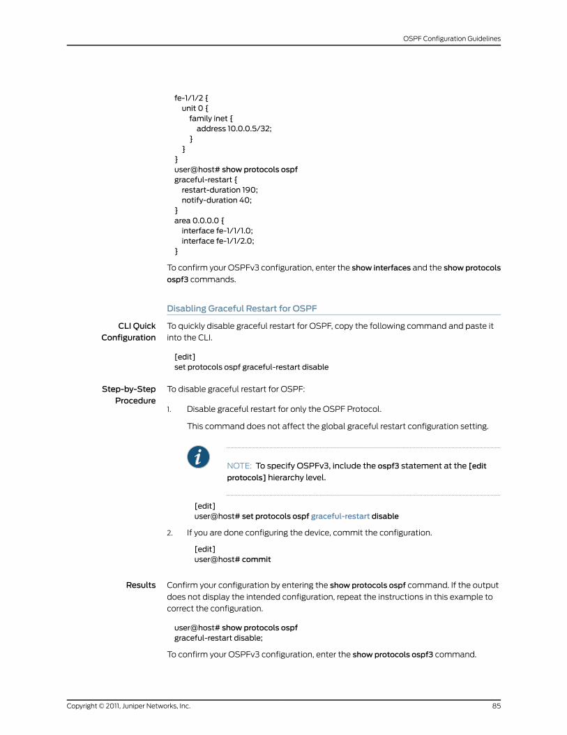
fe-1/1/2 {unit 0 {family inet {address 10.0.0.5/32;
}}
}user@host# show protocols ospfgraceful-restart {restart-duration 190;notify-duration 40;
}area 0.0.0.0 {interface fe-1/1/1.0;interface fe-1/1/2.0;
}
To confirm your OSPFv3 configuration, enter the show interfaces and the showprotocols
ospf3 commands.
Disabling Graceful Restart for OSPF
CLI QuickConfiguration
To quickly disable graceful restart for OSPF, copy the following command and paste it
into the CLI.
[edit]set protocols ospf graceful-restart disable
Step-by-StepProcedure
To disable graceful restart for OSPF:
Disable graceful restart for only the OSPF Protocol.1.
This command does not affect the global graceful restart configuration setting.
NOTE: To specify OSPFv3, include the ospf3 statement at the [edit
protocols] hierarchy level.
[edit]user@host# set protocols ospf graceful-restart disable
2. If you are done configuring the device, commit the configuration.
[edit]user@host# commit
Results Confirm your configuration by entering the show protocols ospf command. If the output
does not display the intended configuration, repeat the instructions in this example to
correct the configuration.
user@host# show protocols ospfgraceful-restart disable;
To confirm your OSPFv3 configuration, enter the show protocols ospf3 command.
85Copyright © 2011, Juniper Networks, Inc.
OSPF Configuration Guidelines
Verification
Confirm that the configuration is working properly.
• Verifying the OSPF Graceful Restart Configuration on page 86
• Verifying Graceful Restart Status on page 86
Verifying the OSPF Graceful Restart Configuration
Purpose Verify information about your OSPF graceful restart configuration. The Restart field
displays the status of graceful restart as either enabled or disabled, the Restart duration
field displays the time period for complete reacquisition of OSPF neighbors, and the
Restart grace period displays the time period for which the neighbors should consider
the restart routing device as part of the topology.
Action From operational mode, enter the show ospf overview command for OSPFv2, and enter
the show ospf3 overview command for OSPFv3.
Verifying Graceful Restart Status
Purpose Verify the status of graceful restart. The Restart State field displays Pending if the restart
has not completed or Complete if the restart has finished, and the Path selection timeout
field indicates the amount of time remaining until graceful restart is declared complete.
There is a more detailed Restart State field that displays a list of protocols that have
completed graceful restart or have not yet completed graceful restart for the specified
routing table.
Action From operational mode, enter the show route instance detail command.
RelatedDocumentation
Graceful Restart for OSPF Overview•
• Example: Configuring the Helper Capability Mode for OSPFv2 Graceful Restart
• Example: Configuring the Helper Capability Mode for OSPFv3 Graceful Restart
• Example: Disabling Strict LSA Checking for OSPF Graceful Restart
Example: Configuring SPF AlgorithmOptions for OSPF
This example shows how to configure the SPF algorithm options. The SPF options control
the timers that dictate when the SPF algorithm runs.
• Requirements on page 87
• Overview on page 87
• Configuration on page 88
• Verification on page 89
Copyright © 2011, Juniper Networks, Inc.86
Junos OS OSPF Configuration Guide
Requirements
Before you begin:
• Configure the device interfaces. See the JunosOSNetwork InterfacesConfigurationGuide.
• Configure the router identifiers for the devices in your OSPF network. See Example:
Configuring an OSPF Router Identifier.
• Control OSPF designated router election. See “Example: Controlling OSPF Designated
Router Election” on page 50
• Configure a single-area OSPF network. See Example: Configuring a Single-Area OSPF
Network.
• Configure a multiarea OSPF network. See Example: Configuring a Multiarea OSPF
Network.
Overview
OSPF uses the SPF algorithm to determine the route to reach each destination. All routing
devices in an area run this algorithm in parallel, storing the results in their individual
topology databases. Routing devices with interfaces to multiple areas run multiple copies
of the algorithm. The SPF options control the timers used by the SPF algorithm.
Before you modify any of the default settings, you should have a good understanding of
your network environment and requirements.
This example shows how to configure the options for running the SPF algorithm. You
include the spf-options statement and the following options:
• delay—Configures the amount of time (in milliseconds) between the detection of a
topology and when the SPF actually runs. When you modify the delay timer, consider
your requirements for network reconvergence. For example, you want to specify a timer
value that can help you identify abnormalities in the network, but allow a stable network
to reconverge quickly. By default, the SPF algorithm runs 200 milliseconds after the
detection of a topology. The range is from 50 through 8000 milliseconds.
• rapid-runs—Configures the maximum number of times that the SPF algorithm can run
in succession before the hold-down timer begins. By default, the number of SPF
calculations that can occur in succession is 3. The range is from 1 through 5. Each SPF
algorithm is run after the configured SPF delay. When the maximum number of SPF
calculations occurs, the hold-down timer begins. Any subsequent SPF calculation is
not run until the hold-down timer expires.
• holddown—Configures the time to hold down, or wait, before running another SPF
calculation after the SPF algorithm has run in succession the configured maximum
number of times. By default, the hold down time is 5000 milliseconds. The range is
from 2000 through 20,000 milliseconds. If the network stabilizes during the holddown
period and the SPF algorithm does not need to run again, the system reverts to the
configured values for the delay and rapid-runs statements.
87Copyright © 2011, Juniper Networks, Inc.
OSPF Configuration Guidelines
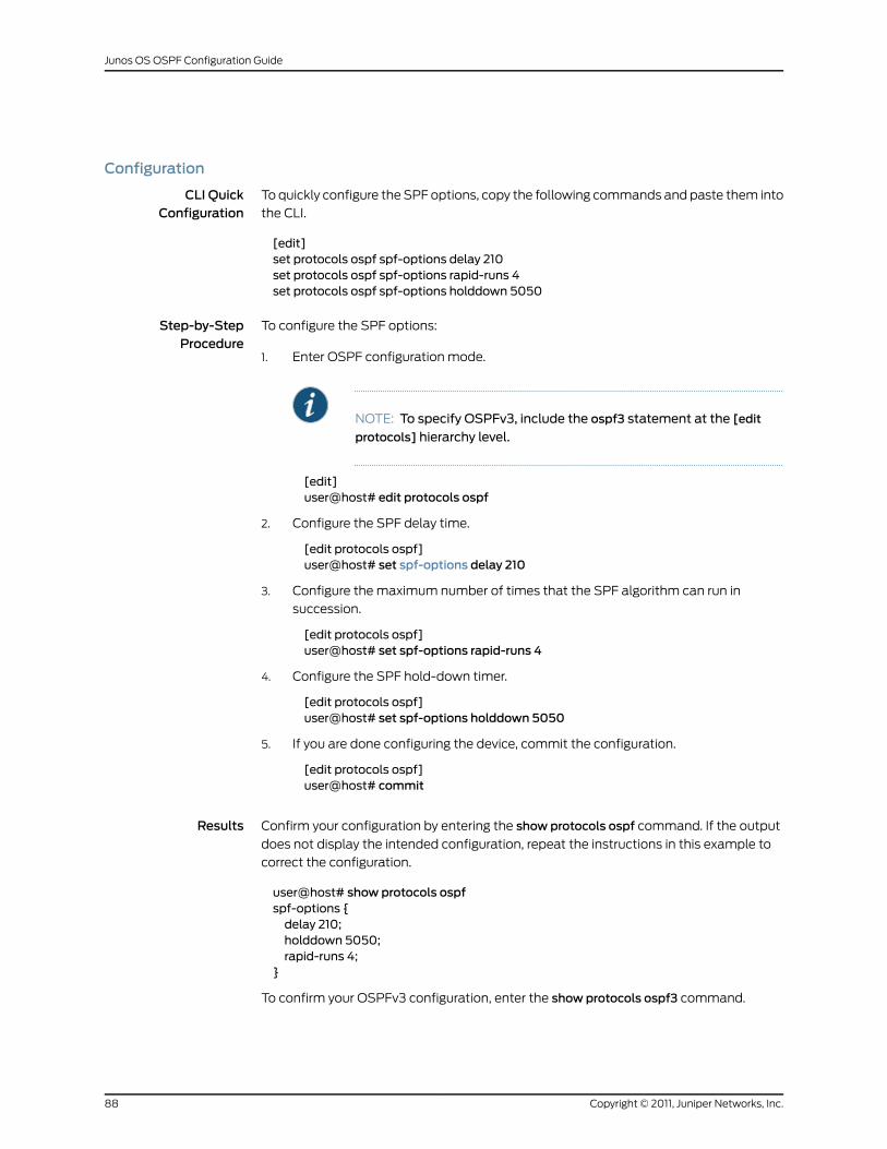
Configuration
CLI QuickConfiguration
To quickly configure the SPF options, copy the following commands and paste them into
the CLI.
[edit]set protocols ospf spf-options delay 210set protocols ospf spf-options rapid-runs 4set protocols ospf spf-options holddown 5050
Step-by-StepProcedure
To configure the SPF options:
Enter OSPF configuration mode.1.
NOTE: To specify OSPFv3, include the ospf3 statement at the [edit
protocols] hierarchy level.
[edit]user@host# edit protocols ospf
2. Configure the SPF delay time.
[edit protocols ospf]user@host# set spf-options delay 210
3. Configure the maximum number of times that the SPF algorithm can run in
succession.
[edit protocols ospf]user@host# set spf-options rapid-runs 4
4. Configure the SPF hold-down timer.
[edit protocols ospf]user@host# set spf-options holddown 5050
5. If you are done configuring the device, commit the configuration.
[edit protocols ospf]user@host# commit
Results Confirm your configuration by entering the show protocols ospf command. If the output
does not display the intended configuration, repeat the instructions in this example to
correct the configuration.
user@host# show protocols ospfspf-options {delay 210;holddown 5050;rapid-runs 4;
}
To confirm your OSPFv3 configuration, enter the show protocols ospf3 command.
Copyright © 2011, Juniper Networks, Inc.88
Junos OS OSPF Configuration Guide
Verification
Confirm that the configuration is working properly.
Verifying SPFOptions
Purpose Verify that SPF is operating per your network requirements. Review the SPF delay field,
the SPF holddown field, and the SPF rapid runs fields.
Action From operational mode, enter the show ospf overview command for OSPFv2, and enter
the show ospf3 overview command for OSPFv3.
RelatedDocumentation
Understanding the SPF Algorithm Options for OSPF•
Example: Configuring a Passive OSPF Interface
This example shows how to configure a passive OSPF interface. A passive OSPF interface
advertises its address but does not run the OSPF protocol.
• Requirements on page 89
• Overview on page 89
• Configuration on page 90
• Verification on page 91
Requirements
Before you begin:
• Configure the device interfaces. See the JunosOSNetwork InterfacesConfigurationGuide.
• Configure the router identifiers for the devices in your OSPF network. See Example:
Configuring an OSPF Router Identifier.
• Configure a single-area OSPF network. See Example: Configuring a Single-Area OSPF
Network.
• Configure a multiarea OSPF network. See Example: Configuring a Multiarea OSPF
Network.
Overview
By default, OSPF must be configured on an interface for direct interface addresses to be
advertised as interior routes. To advertise the direct interface addresses without actually
running OSPF on that interface (adjacencies are not formed and hello packets are not
generated), you configure that interface as a passive interface.
Enabling OSPF on an interface (by including the interface statement), disabling it (by
including the disable statement), and not actually having OSPF run on an interface (by
including the passive statement) are mutually exclusive states.
89Copyright © 2011, Juniper Networks, Inc.
OSPF Configuration Guidelines
NOTE: If you do not want to see notifications for state changes in a passiveOSPF interface, you can disable theOSPF traps for the interface by includingtheno-interface-state-trapsstatement.Theno-interface-state-trapsstatement
is supported only for OSPFv2.
In this example, you configure interface ge-0/2/0 as a passive OSPF interface in area
0.0.0.1 by including the passive statement.
Configuration
CLI QuickConfiguration
To quickly configure a passive OSPF interface, copy the following command and paste
it into the CLI.
[edit]set protocols ospf area 0.0.0.1 interface ge-0/2/0 passive
Step-by-StepProcedure
To configure a passive OSPF interface:
Create an OSPF area.1.
NOTE: For an OSPFv3 interface, include the ospf3 statement at the
[edit protocols] hierarchy level.
[edit]user@host# edit protocols ospf area 0.0.0.1
2. Configure the passive interface.
[edit protocols ospf area 0.0.0.1 ]user@host# set interface ge-0/2/0 passive
3. If you are done configuring the device, commit the configuration.
[edit protocols ospf area 0.0.0.1]user@host# commit
Results Confirm your configuration by entering the show protocols ospf command. If the output
does not display the intended configuration, repeat the instructions in this example to
correct the configuration.
user@host# show protocols ospfarea 0.0.0.1 {interface ge-0/2/0.0 {passive;
}}
To confirm your OSPFv3 configuration, enter the show protocols ospf3 command.
Copyright © 2011, Juniper Networks, Inc.90
Junos OS OSPF Configuration Guide
Verification
Confirm that the configuration is working properly.
Verifying the Status of OSPF Interfaces
Purpose Verify the status of the OSPF interface. If the interface is passive, the Adj count field is 0
because no adjacencies have been formed. Next to this field, you might also see the word
Passive.
Action From operational mode, enter the show ospf interface detail command for OSPFv2, and
enter the show ospf3 interface detail command for OSPFv3.
RelatedDocumentation
OSPF Configuration Overview•
• About OSPF Interfaces
Example: Configuring OSPF Passive Traffic EngineeringMode
This example shows how to configure OSPF passive mode for traffic engineering on an
inter-AS interface. The AS boundary router link between the EBGP peers must be a directly
connected link and must be configured as a passive traffic engineering link.
• Requirements on page 91
• Overview on page 92
• Configuration on page 92
• Verification on page 93
Requirements
Before you begin:
• Configure the device interfaces. See the JunosOSNetwork InterfacesConfigurationGuide.
• Configure BGP per your network requirements. See the Junos OS Routing Protocols
Configuration Guide.
• Configure the LSP per your network requirements. See the Junos OSMPLS Applications
Configuration Guide.
• Configure the router identifiers for the devices in your OSPF network. See Example:
Configuring an OSPF Router Identifier.
• Control OSPF designated router election. See “Example: Controlling OSPF Designated
Router Election” on page 50
• Configure a single-area OSPF network. See Example: Configuring a Single-Area OSPF
Network.
• Configure a multiarea OSPF network. See Example: Configuring a Multiarea OSPF
Network.
91Copyright © 2011, Juniper Networks, Inc.
OSPF Configuration Guidelines
Overview
You can configure OSPF passive mode for traffic engineering on an inter-AS interface.
The address used for the remote node of the OSPF passive traffic engineering link must
be the same as the address used for the EBGP link. In this example, you configure interface
so-1/1/0 in area 0.0.0.1 as the inter-AS link to distribute traffic engineering information
with OSPF within the AS and include the following settings:
• passive—Advertises the direct interface addresses on an interface without actually
running OSPF on that interface. A passive interface is one for which the address
information is advertised as an internal route in OSPF, but on which the protocol does
not run.
• traffic-engineering—Configures an interface in OSPF passive traffic-engineering mode
to enable dynamic discovery of OSPF AS boundary routers. By default, OSPF passive
traffic-engineering mode is disabled.
• remote-node-id—Specifies the IP address at the far end of the inter-AS link. In this
example, the remote IP address is 192.168.207.2.
Configuration
To quickly configure OSPF passive mode for traffic engineering, copy the following
command, remove any line breaks, and paste it into the CLI.
[edit]setprotocolsospfarea0.0.0.1 interfaceso-1/1/0passive traffic-engineering remote-node-id192.168.207.2
Step-by-StepProcedure
To configure OSPF passive traffic engineering mode:
Create an OSPF area.1.
NOTE: To specify OSPFv3, include the ospf3 statement at the [edit
protocols] hierarchy level.
[edit]user@host# set protocols ospf area 0.0.0.1
2. Configure interface so-1/1/0as a passive interface configured for traffic engineering,
and specify the IP address at the far end of the inter-AS link.
[edit protocols ospf area 0.0.0.1]user@host# set interface so-1/1/0 passive traffic-engineering remote-node-id192.168.207.2
3. If you are done configuring the device, commit the configuration.
[edit protocols ospf]user@host# commit
Copyright © 2011, Juniper Networks, Inc.92
Junos OS OSPF Configuration Guide
Results Confirm your configuration by entering the show protocols ospf command. If the output
does not display the intended configuration, repeat the instructions in this example to
correct the configuration.
user@host# show protocols ospfarea 0.0.0.1 {interface so-1/1/0.0 {passive {traffic-engineering {remote-node-id 192.168.207.2;
}}
}}
To confirm your OSPFv3 configuration, enter the show protocols ospf3 command.
Verification
Confirm that the configuration is working properly.
Verifying the Status of OSPF Interfaces
Purpose Verify the status of OSPF interfaces. If the interface is passive, the Adj count field is 0
because no adjacencies have been formed. Next to this field, you might also see the word
Passive.
Action From operational mode, enter the show ospf interface detail command for OSPFv2, and
enter the show ospf3 interface detail command for OSPFv3.
RelatedDocumentation
OSPF Passive Traffic Engineering Mode•
Example: Advertising Label-Switched Paths into OSPFv2
This example shows how to advertise LSPs into OSPFv2.
• Requirements on page 93
• Overview on page 93
• Configuration on page 95
• Verification on page 104
Requirements
Before you begin, configure the device interfaces. See the Junos OS Network Interfaces
Configuration Guide.
Overview
To advertise an LSP into OSPFv2, you define the LSP and configure OSPFv2 to route
traffic using the LSP. By doing this, you can use the LSP to control the shortest path
93Copyright © 2011, Juniper Networks, Inc.
OSPF Configuration Guidelines
between two points on the network. You might choose to do this if you want to have
OSPF traffic routed along the LSP instead of having OSPF use the default best-effort
routing.
In this example, you configure the following to advertise an LSP into OSPFv2:
• BGP
For all routing devices, configure the local AS number 65000 and define the IBGP
group that recognizes the specified BGP systems as peers. All members are internal
to the local AS, so you configure an internal group with a full list of peers. You also
include the peer AS group, which is the same as the local AS number that you configure.
• MPLS
For all routing devices, configure the protocol family on each transit logical interface
and enable MPLS on all interfaces, except for the management interface (fxp0.0).
Specify the mpls protocol family type.
• RSVP
For all routing devices, enable RSVP on all interfaces, except for the management
interface (fxp0.0). You enable RSVP on the devices in this network to ensure that the
interfaces can signal the LSP.
• OSPFv2
For all routing devices, use the loopback address to assign the router ID, administratively
group all of the devices into OSPF area 0.0.0.0, add all of the interfaces participating
in OSPF to area 0.0.0.0, and disable OSPF on the management interface (fxp0.0).
• Label-switched path
On the ingress routing device R1, which is the beginning (or head end) of the LSP,
configure an LSP with an explicit path. The explicit path indicates that the LSP must
go to the next specified IP address in the path without traversing other nodes. In this
example, you create an LSP named R1-to-R6, and you specify the IP address of the
egress routing device R6.
• Advertise the LSP in OSPFv2
On the ingress routing device R1, you advertise the LSP as a point-to-point link into
OSPFv2. You can optionally assign a metric to have the LSP be the more or less
preferred path to the destination.
Figure 5 on page 95 shows a sample network topology that consists of the following:
• BGP is configured on all routing devices, with one local autonomous system (AS)
65000 that contains three routing devices:
• R1—Device R1 is the ingress device with a router ID of 10.0.0.1. Interface so-0/0/2
connects to Device R3.
• R3—Device R3 is the transit device with a router ID of 10.0.0.3. Interface so-0/0/2
connects to Device R1, and interface so-0/0/3 connects to Device R6.
Copyright © 2011, Juniper Networks, Inc.94
Junos OS OSPF Configuration Guide
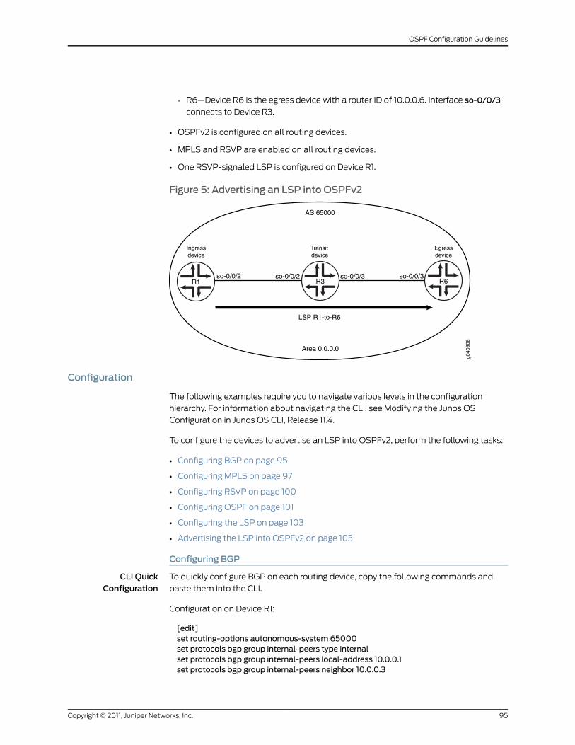
• R6—Device R6 is the egress device with a router ID of 10.0.0.6. Interface so-0/0/3
connects to Device R3.
• OSPFv2 is configured on all routing devices.
• MPLS and RSVP are enabled on all routing devices.
• One RSVP-signaled LSP is configured on Device R1.
Figure 5: Advertising an LSP into OSPFv2
g040
908
R1 R3
AS 65000
LSP R1-to-R6
so-0/0/2R6
Area 0.0.0.0
so-0/0/3so-0/0/2
Ingressdevice
Transitdevice
Egressdevice
so-0/0/3
Configuration
The following examples require you to navigate various levels in the configuration
hierarchy. For information about navigating the CLI, see Modifying the Junos OS
Configuration in Junos OS CLI, Release 11.4.
To configure the devices to advertise an LSP into OSPFv2, perform the following tasks:
• Configuring BGP on page 95
• Configuring MPLS on page 97
• Configuring RSVP on page 100
• Configuring OSPF on page 101
• Configuring the LSP on page 103
• Advertising the LSP into OSPFv2 on page 103
Configuring BGP
CLI QuickConfiguration
To quickly configure BGP on each routing device, copy the following commands and
paste them into the CLI.
Configuration on Device R1:
[edit]set routing-options autonomous-system 65000set protocols bgp group internal-peers type internalset protocols bgp group internal-peers local-address 10.0.0.1set protocols bgp group internal-peers neighbor 10.0.0.3
95Copyright © 2011, Juniper Networks, Inc.
OSPF Configuration Guidelines
set protocols bgp group internal-peers neighbor 10.0.0.6set protocols bgp group internal-peers peer-as 65000
Configuration on Device R3:
[edit]set routing-options autonomous-system 65000set protocols bgp group internal-peers type internalset protocols bgp group internal-peers local-address 10.0.0.3set protocols bgp group internal-peers neighbor 10.0.0.1set protocols bgp group internal-peers neighbor 10.0.0.6set protocols bgp group internal-peers peer-as 65000
Configuration on Device R6:
[edit]set routing-options autonomous-system 65000set protocols bgp group internal-peers type internalset protocols bgp group internal-peers local-address 10.0.0.6set protocols bgp group internal-peers neighbor 10.0.0.1set protocols bgp group internal-peers neighbor 10.0.0.3set protocols bgp group internal-peers peer-as 65000
Step-by-StepProcedure
To configure BGP:
On each routing device, configure the local AS number.1.
[edit]user@R1# set routing-options autonomous-system 65000
[edit]user@R3# set routing-options autonomous-system 65000
[edit]user@R6# set routing-options autonomous-system 65000
2. On each routing device, configure the internal BGP neighbor connections.
[edit]user@R1# set protocols bgp group internal-peers type internaluser@R1# set protocols bgp group internal-peers local-address 10.0.0.1user@R1# set protocols bgp group internal-peers neighbor 10.0.0.3user@R1# set protocols bgp group internal-peers neighbor 10.0.0.6user@R1# set protocols bgp group internal-peers peer-as 65000
[edit]user@R3# set protocols bgp group internal-peers type internaluser@R3# set protocols bgp group internal-peers local-address 10.0.0.3user@R3# set protocols bgp group internal-peers neighbor 10.0.0.1user@R3# set protocols bgp group internal-peers neighbor 10.0.0.6user@R3# set protocols bgp group internal-peers peer-as 65000
[edit]user@R6# set protocols bgp group internal-peers type internaluser@R6# set protocols bgp group internal-peers local-address 10.0.0.6user@R6# set protocols bgp group internal-peers neighbor 10.0.0.1user@R6# set protocols bgp group internal-peers neighbor 10.0.0.3user@R6# set protocols bgp group internal-peers peer-as 65000
3. If you are done configuring the devices, commit the configuration.
Copyright © 2011, Juniper Networks, Inc.96
Junos OS OSPF Configuration Guide
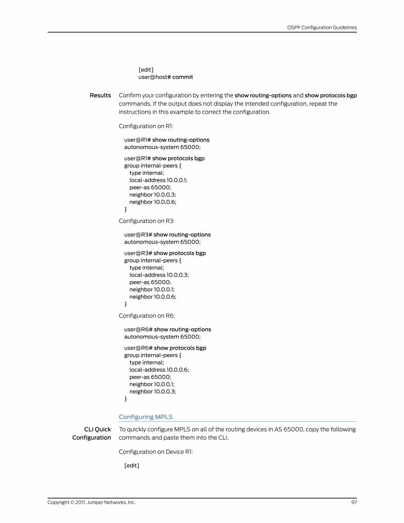
[edit]user@host# commit
Results Confirm your configuration by entering the show routing-options and showprotocols bgp
commands. If the output does not display the intended configuration, repeat the
instructions in this example to correct the configuration.
Configuration on R1:
user@R1# show routing-optionsautonomous-system 65000;
user@R1# show protocols bgpgroup internal-peers {type internal;local-address 10.0.0.1;peer-as 65000;neighbor 10.0.0.3;neighbor 10.0.0.6;
}
Configuration on R3:
user@R3# show routing-optionsautonomous-system 65000;
user@R3# show protocols bgpgroup internal-peers {type internal;local-address 10.0.0.3;peer-as 65000;neighbor 10.0.0.1;neighbor 10.0.0.6;
}
Configuration on R6:
user@R6# show routing-optionsautonomous-system 65000;
user@R6# show protocols bgpgroup internal-peers {type internal;local-address 10.0.0.6;peer-as 65000;neighbor 10.0.0.1;neighbor 10.0.0.3;
}
ConfiguringMPLS
CLI QuickConfiguration
To quickly configure MPLS on all of the routing devices in AS 65000, copy the following
commands and paste them into the CLI.
Configuration on Device R1:
[edit]
97Copyright © 2011, Juniper Networks, Inc.
OSPF Configuration Guidelines
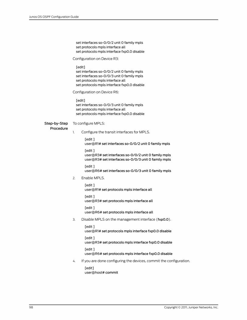
set interfaces so-0/0/2 unit 0 family mplsset protocols mpls interface allset protocols mpls interface fxp0.0 disable
Configuration on Device R3:
[edit]set interfaces so-0/0/2 unit 0 family mplsset interfaces so-0/0/3 unit 0 family mplsset protocols mpls interface allset protocols mpls interface fxp0.0 disable
Configuration on Device R6:
[edit]set interfaces so-0/0/3 unit 0 family mplsset protocols mpls interface allset protocols mpls interface fxp0.0 disable
Step-by-StepProcedure
To configure MPLS:
Configure the transit interfaces for MPLS.1.
[edit ]user@R1# set interfaces so-0/0/2 unit 0 family mpls
[edit ]user@R3# set interfaces so-0/0/2 unit 0 family mplsuser@R3# set interfaces so-0/0/3 unit 0 family mpls
[edit ]user@R6# set interfaces so-0/0/3 unit 0 family mpls
2. Enable MPLS.
[edit ]user@R1# set protocolsmpls interface all
[edit ]user@R3# set protocolsmpls interface all
[edit ]user@R6# set protocolsmpls interface all
3. Disable MPLS on the management interface (fxp0.0).
[edit ]user@R1# set protocolsmpls interface fxp0.0 disable
[edit ]user@R3# set protocolsmpls interface fxp0.0 disable
[edit ]user@R6# set protocolsmpls interface fxp0.0 disable
4. If you are done configuring the devices, commit the configuration.
[edit]user@host# commit
Copyright © 2011, Juniper Networks, Inc.98
Junos OS OSPF Configuration Guide
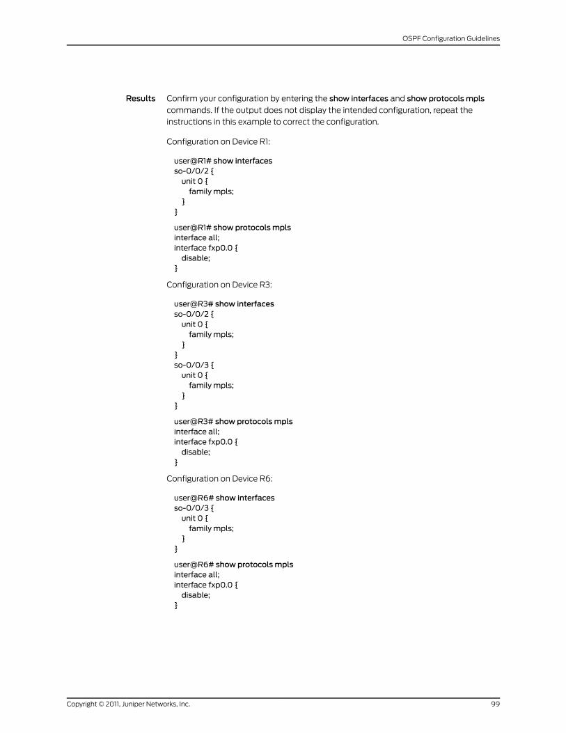
Results Confirm your configuration by entering the show interfaces and show protocolsmpls
commands. If the output does not display the intended configuration, repeat the
instructions in this example to correct the configuration.
Configuration on Device R1:
user@R1# show interfacesso-0/0/2 {unit 0 {family mpls;
}}
user@R1# show protocolsmplsinterface all;interface fxp0.0 {disable;
}
Configuration on Device R3:
user@R3# show interfacesso-0/0/2 {unit 0 {family mpls;
}}so-0/0/3 {unit 0 {family mpls;
}}
user@R3# show protocolsmplsinterface all;interface fxp0.0 {disable;
}
Configuration on Device R6:
user@R6# show interfacesso-0/0/3 {unit 0 {family mpls;
}}
user@R6# show protocolsmplsinterface all;interface fxp0.0 {disable;
}
99Copyright © 2011, Juniper Networks, Inc.
OSPF Configuration Guidelines
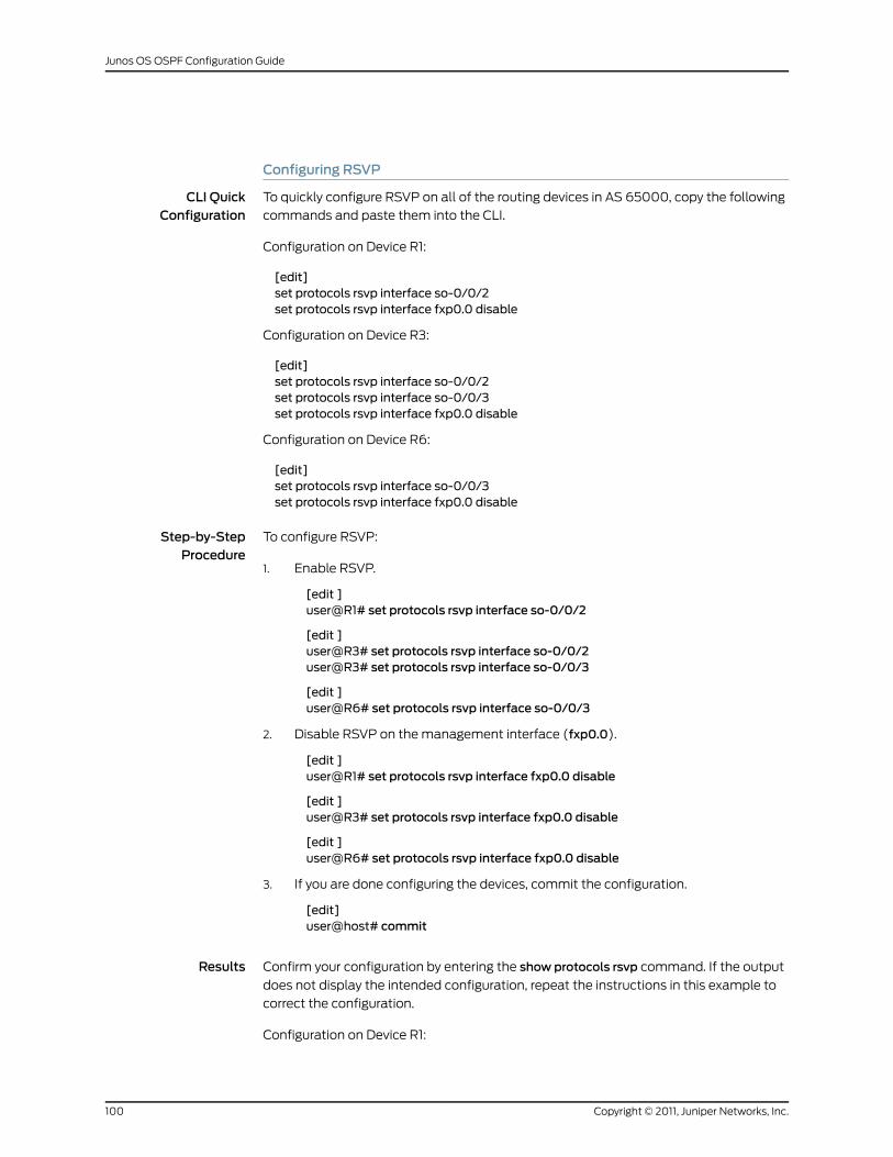
Configuring RSVP
CLI QuickConfiguration
To quickly configure RSVP on all of the routing devices in AS 65000, copy the following
commands and paste them into the CLI.
Configuration on Device R1:
[edit]set protocols rsvp interface so-0/0/2set protocols rsvp interface fxp0.0 disable
Configuration on Device R3:
[edit]set protocols rsvp interface so-0/0/2set protocols rsvp interface so-0/0/3set protocols rsvp interface fxp0.0 disable
Configuration on Device R6:
[edit]set protocols rsvp interface so-0/0/3set protocols rsvp interface fxp0.0 disable
Step-by-StepProcedure
To configure RSVP:
Enable RSVP.1.
[edit ]user@R1# set protocols rsvp interface so-0/0/2
[edit ]user@R3# set protocols rsvp interface so-0/0/2user@R3# set protocols rsvp interface so-0/0/3
[edit ]user@R6# set protocols rsvp interface so-0/0/3
2. Disable RSVP on the management interface (fxp0.0).
[edit ]user@R1# set protocols rsvp interface fxp0.0 disable
[edit ]user@R3# set protocols rsvp interface fxp0.0 disable
[edit ]user@R6# set protocols rsvp interface fxp0.0 disable
3. If you are done configuring the devices, commit the configuration.
[edit]user@host# commit
Results Confirm your configuration by entering the show protocols rsvp command. If the output
does not display the intended configuration, repeat the instructions in this example to
correct the configuration.
Configuration on Device R1:
Copyright © 2011, Juniper Networks, Inc.100
Junos OS OSPF Configuration Guide
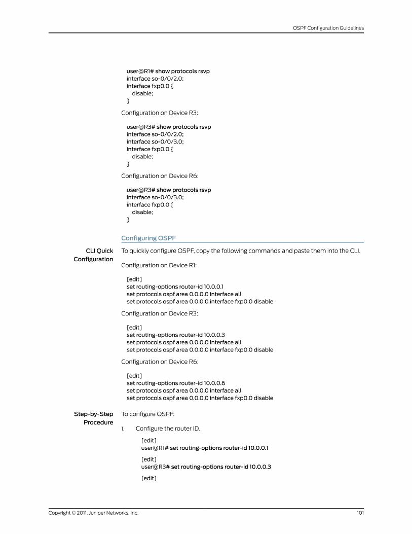
user@R1# show protocols rsvpinterface so-0/0/2.0;interface fxp0.0 {disable;
}
Configuration on Device R3:
user@R3# show protocols rsvpinterface so-0/0/2.0;interface so-0/0/3.0;interface fxp0.0 {disable;
}
Configuration on Device R6:
user@R3# show protocols rsvpinterface so-0/0/3.0;interface fxp0.0 {disable;
}
Configuring OSPF
CLI QuickConfiguration
To quickly configure OSPF, copy the following commands and paste them into the CLI.
Configuration on Device R1:
[edit]set routing-options router-id 10.0.0.1set protocols ospf area 0.0.0.0 interface allset protocols ospf area 0.0.0.0 interface fxp0.0 disable
Configuration on Device R3:
[edit]set routing-options router-id 10.0.0.3set protocols ospf area 0.0.0.0 interface allset protocols ospf area 0.0.0.0 interface fxp0.0 disable
Configuration on Device R6:
[edit]set routing-options router-id 10.0.0.6set protocols ospf area 0.0.0.0 interface allset protocols ospf area 0.0.0.0 interface fxp0.0 disable
Step-by-StepProcedure
To configure OSPF:
Configure the router ID.1.
[edit]user@R1# set routing-options router-id 10.0.0.1
[edit]user@R3# set routing-options router-id 10.0.0.3
[edit]
101Copyright © 2011, Juniper Networks, Inc.
OSPF Configuration Guidelines
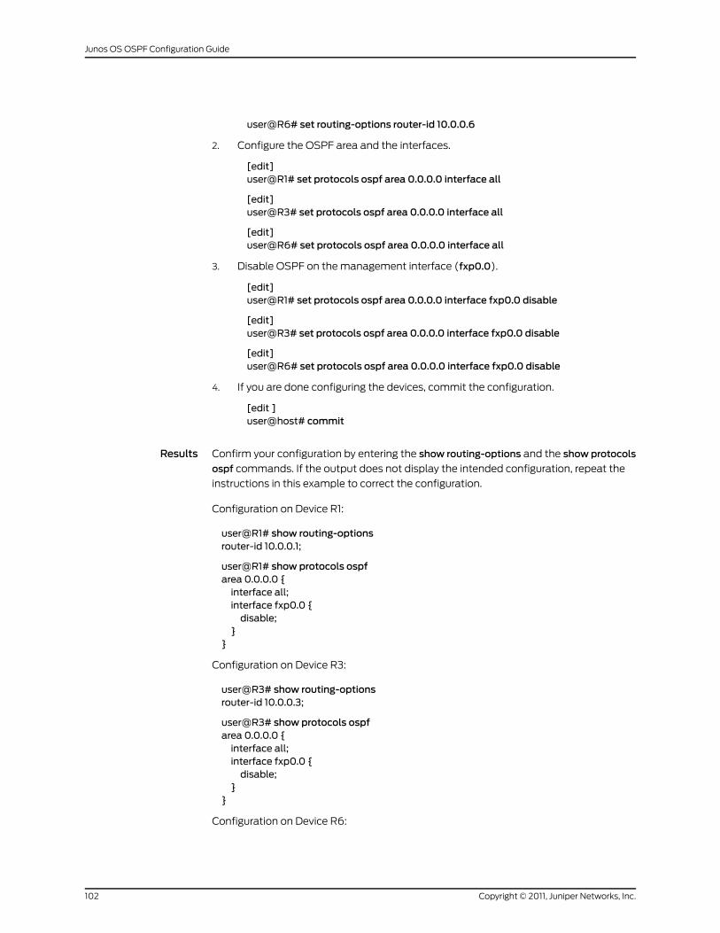
user@R6# set routing-options router-id 10.0.0.6
2. Configure the OSPF area and the interfaces.
[edit]user@R1# set protocols ospf area 0.0.0.0 interface all
[edit]user@R3# set protocols ospf area 0.0.0.0 interface all
[edit]user@R6# set protocols ospf area 0.0.0.0 interface all
3. Disable OSPF on the management interface (fxp0.0).
[edit]user@R1# set protocols ospf area 0.0.0.0 interface fxp0.0 disable
[edit]user@R3# set protocols ospf area 0.0.0.0 interface fxp0.0 disable
[edit]user@R6# set protocols ospf area 0.0.0.0 interface fxp0.0 disable
4. If you are done configuring the devices, commit the configuration.
[edit ]user@host# commit
Results Confirm your configuration by entering the show routing-options and the show protocols
ospf commands. If the output does not display the intended configuration, repeat the
instructions in this example to correct the configuration.
Configuration on Device R1:
user@R1# show routing-optionsrouter-id 10.0.0.1;
user@R1# show protocols ospfarea 0.0.0.0 {interface all;interface fxp0.0 {disable;
}}
Configuration on Device R3:
user@R3# show routing-optionsrouter-id 10.0.0.3;
user@R3# show protocols ospfarea 0.0.0.0 {interface all;interface fxp0.0 {disable;
}}
Configuration on Device R6:
Copyright © 2011, Juniper Networks, Inc.102
Junos OS OSPF Configuration Guide
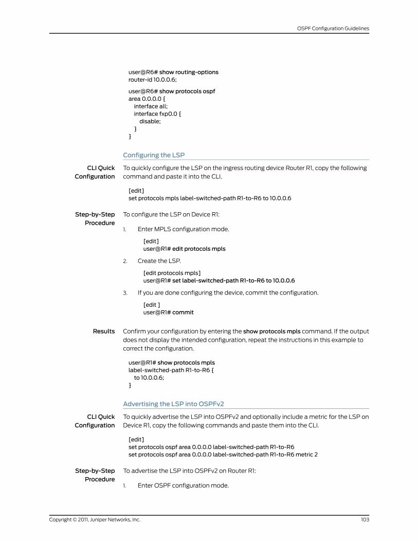
user@R6# show routing-optionsrouter-id 10.0.0.6;
user@R6# show protocols ospfarea 0.0.0.0 {interface all;interface fxp0.0 {disable;
}}
Configuring the LSP
CLI QuickConfiguration
To quickly configure the LSP on the ingress routing device Router R1, copy the following
command and paste it into the CLI.
[edit]set protocols mpls label-switched-path R1-to-R6 to 10.0.0.6
Step-by-StepProcedure
To configure the LSP on Device R1:
Enter MPLS configuration mode.1.
[edit]user@R1# edit protocolsmpls
2. Create the LSP.
[edit protocols mpls]user@R1# set label-switched-path R1-to-R6 to 10.0.0.6
3. If you are done configuring the device, commit the configuration.
[edit ]user@R1# commit
Results Confirm your configuration by entering the show protocolsmpls command. If the output
does not display the intended configuration, repeat the instructions in this example to
correct the configuration.
user@R1# show protocolsmplslabel-switched-path R1-to-R6 {to 10.0.0.6;
}
Advertising the LSP into OSPFv2
CLI QuickConfiguration
To quickly advertise the LSP into OSPFv2 and optionally include a metric for the LSP on
Device R1, copy the following commands and paste them into the CLI.
[edit]set protocols ospf area 0.0.0.0 label-switched-path R1-to-R6set protocols ospf area 0.0.0.0 label-switched-path R1-to-R6metric 2
Step-by-StepProcedure
To advertise the LSP into OSPFv2 on Router R1:
Enter OSPF configuration mode.1.
103Copyright © 2011, Juniper Networks, Inc.
OSPF Configuration Guidelines
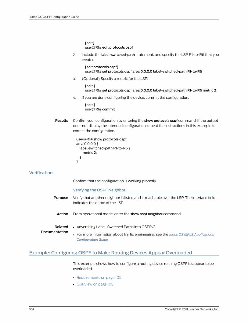
[edit]user@R1# edit protocols ospf
2. Include the label-switched-path statement, and specify the LSP R1-to-R6 that you
created.
[edit protocols ospf]user@R1# set protocols ospf area 0.0.0.0 label-switched-path R1-to-R6
3. (Optional) Specify a metric for the LSP.
[edit ]user@R1# set protocols ospf area 0.0.0.0 label-switched-path R1-to-R6metric 2
4. If you are done configuring the device, commit the configuration.
[edit ]user@R1# commit
Results Confirm your configuration by entering the show protocols ospf command. If the output
does not display the intended configuration, repeat the instructions in this example to
correct the configuration.
user@R1# show protocols ospfarea 0.0.0.0 {label-switched-path R1-to-R6 {metric 2;
}}
Verification
Confirm that the configuration is working properly.
Verifying the OSPF Neighbor
Purpose Verify that another neighbor is listed and is reachable over the LSP. The interface field
indicates the name of the LSP.
Action From operational mode, enter the show ospf neighbor command.
RelatedDocumentation
Advertising Label-Switched Paths into OSPFv2•
• For more information about traffic engineering, see the Junos OSMPLS Applications
Configuration Guide
Example: Configuring OSPF toMake Routing Devices Appear Overloaded
This example shows how to configure a routing device running OSPF to appear to be
overloaded.
• Requirements on page 105
• Overview on page 105
Copyright © 2011, Juniper Networks, Inc.104
Junos OS OSPF Configuration Guide
• Configuration on page 105
• Verification on page 106
Requirements
Before you begin:
• Configure the device interfaces. See the JunosOSNetwork InterfacesConfigurationGuide.
• Configure the router identifiers for the devices in your OSPF network. See Example:
Configuring an OSPF Router Identifier.
• Control OSPF designated router election. See “Example: Controlling OSPF Designated
Router Election” on page 50
• Configure a single-area OSPF network. See Example: Configuring a Single-Area OSPF
Network.
• Configure a multiarea OSPF network. See Example: Configuring a Multiarea OSPF
Network.
Overview
You can configure a local routing device running OSPF to appear to be overloaded, which
allows the local routing device to participate in OSPF routing, but not for transit traffic.
When configured, the transit interface metrics are set to the maximum value of 65535.
This example includes the following settings:
• overload—Configures the local routing device so it appears to be overloaded. You might
configure this if you want the routing device to participate in OSPF routing, but do not
want it to be used for transit traffic, or you are performing maintenance on a routing
device in a production network.
• timeout seconds—(Optional) Specifies the number of seconds at which the overload
is reset. If no timeout interval is specified, the routing device remains in the overload
state until the overload statement is deleted or a timeout is set. In this example, you
configure 60 seconds as the amount of time the routing device remains in the overload
state. By default, the timeout interval is 0 seconds (this value is not configured). The
range is from 60 through 1800 seconds.
Configuration
CLI QuickConfiguration
To quickly configure a local routing device to appear as overloaded, copy the following
command and paste it into the CLI.
[edit]set protocols ospf overload timeout 60
Step-by-StepProcedure
To configure a local routing device to appear overloaded:
Enter OSPF configuration mode.1.
105Copyright © 2011, Juniper Networks, Inc.
OSPF Configuration Guidelines
NOTE: To specify OSPFv3, include the ospf3 statement at the [edit
protocols] hierarchy level.
[edit]user@host edit protocols ospf
2. Configure the local routing device to be overloaded.
[edit protocols ospf]user@host set overload
3. (Optional) Configure the number of seconds at which overload is reset.
[edit protocols ospf]user@host set overload timeout 60
4. If you are done configuring the device, commit the configuration.
[edit protocols ospf]user@host# commit
Results Confirm your configuration by entering the show protocols ospf command. If the output
does not display the intended configuration, repeat the instructions in this example to
correct the configuration. The output includes the optional timeout statement.
user@host# show protocols ospfoverload timeout 60;
To confirm your OSPFv3 configuration, enter the show protocols ospf3 command.
Verification
Confirm that the configuration is working properly.
• Verifying Traffic Has Moved Off Devices on page 106
• Verifying Transit Interface Metrics on page 106
• Verifying the Overload Configuration on page 107
• Verifying the Viable Next Hop on page 107
Verifying Traffic HasMoved Off Devices
Purpose Verify that the traffic has moved off the upstream devices.
Action From operational mode, enter the show interfaces detail command.
Verifying Transit InterfaceMetrics
Purpose Verify that the transit interface metrics are set to the maximum value of 65535 on the
downstream neighboring device.
Copyright © 2011, Juniper Networks, Inc.106
Junos OS OSPF Configuration Guide
Action From operational mode, enter the show ospf database router detail advertising-router
address command for OSPFv2, and enter the show ospf3 database router detail
advertising-router address command for OSPFv3.
Verifying the Overload Configuration
Purpose Verify that overload is configured by reviewing the Configured overload field. If the overload
timer is also configured, this field also displays the time that remains before it is set to
expire.
Action From operational mode, enter the show ospf overview command for OSPFv2, and the
show ospf3 overview command for OSPFv3.
Verifying the Viable Next Hop
Purpose Verify the viable next hop configuration on the upstream neighboring device. If the
neighboring device is overloaded, it is not used for transit traffic and is not displayed in
the output.
Action From operational mode, enter the show route address command.
RelatedDocumentation
OSPF Overload Function Overview•
Example: Enabling OSPF Traffic Engineering Support
This example shows how to enable OSPF traffic engineering support to advertise the
label-switched path (LSP) metric in summary link-state advertisements (LSAs).
• Requirements on page 107
• Overview on page 108
• Configuration on page 108
• Verification on page 111
Requirements
Before you begin:
• Configure the device interfaces. See the JunosOSNetwork InterfacesConfigurationGuide.
• Configure BGP per your network requirements. See the Junos OS Routing Protocols
Configuration Guide
• Configure MPLS per your network requirements. See the Junos OSMPLS Applications
Configuration Guide.
107Copyright © 2011, Juniper Networks, Inc.
OSPF Configuration Guidelines
Overview
You can configure OSPF to treat an LSP as a link and have other routing devices in the
network use this LSP. To accomplish this, you configure MPLS and OSPF traffic
engineering to advertise the LSP metric in summary LSAs.
In this example, there are four routing devices in area 0.0.0.0, and you want OSPF to
treat the LSP named R1-to-R4 that goes from the ingress Device R1 to the egress Device
R4 as a link.
For OSPF, you enable traffic engineering on all four routing devices in the area by including
the traffic-engineering statement. This configuration ensures that the shortest-path-first
(SPF) algorithm takes into account the LSPs configured under MPLS and configures
OSPF to generate LSAs that carry traffic engineering parameters. You further ensure that
OSPF uses the MPLS LSP as the next hop and advertises the LSP metric in summary
LSAs, by including the optional shortcuts lsp-metric-into-summary statement on the
ingress Device R1.
For MPLS, you enable traffic engineering so that MPLS performs traffic engineering on
both BGP and IGP destinations by including the traffic-engineering bgp-igp statement,
and you include the LSP named R1-to-R4 by including the label-switched-path
lsp-path-name to address statement on the ingress Device R1. The address specified in
the to statement on the ingress Device R1 must match the router ID of the egress Device
R4 for the LSP to function as a direct link to the egress routing device and to be used as
input to the OSPF SPF calculations. In this example, the router ID of the egress Device
R4 is 10.0.0.4.
Configuration
The following example requires you to navigate various levels in the configuration
hierarchy. For information about navigating the CLI, see Modifying the Junos OS
Configuration in Junos OS CLI, Release 11.4.
CLI QuickConfiguration
To quickly enable OSPF traffic engineering support to advertise the LSP metric in summary
LSAs, copy the following commands and paste them into the CLI.
Configuration on R1:
[edit]set routing-options router-id 10.0.0.1set protocols ospf area 0.0.0.0 interface allset protocols ospf area 0.0.0.0 interface fxp0.0 disableset protocols ospf traffic-engineering shortcuts lsp-metric-into-summaryset protocols mpls traffic-engineering bgp-igpset protocols mpls label-switched-path R1-to-R4 to 10.0.0.4
Configuration on R2:
[edit]set routing-options router-id 10.0.0.2set protocols ospf area 0.0.0.0 interface allset protocols ospf area 0.0.0.0 interface fxp0.0 disableset protocols ospf traffic-engineering
Copyright © 2011, Juniper Networks, Inc.108
Junos OS OSPF Configuration Guide
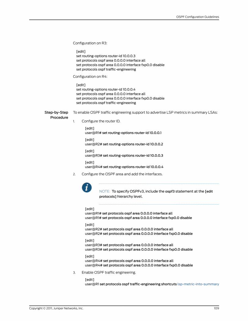
Configuration on R3:
[edit]set routing-options router-id 10.0.0.3set protocols ospf area 0.0.0.0 interface allset protocols ospf area 0.0.0.0 interface fxp0.0 disableset protocols ospf traffic-engineering
Configuration on R4:
[edit]set routing-options router-id 10.0.0.4set protocols ospf area 0.0.0.0 interface allset protocols ospf area 0.0.0.0 interface fxp0.0 disableset protocols ospf traffic-engineering
Step-by-StepProcedure
To enable OSPF traffic engineering support to advertise LSP metrics in summary LSAs:
Configure the router ID.1.
[edit]user@R1# set routing-options router-id 10.0.0.1
[edit]user@R2# set routing-options router-id 10.0.0.2
[edit]user@R3# set routing-options router-id 10.0.0.3
[edit]user@R4# set routing-options router-id 10.0.0.4
2. Configure the OSPF area and add the interfaces.
NOTE: To specify OSPFv3, include the ospf3 statement at the [edit
protocols] hierarchy level.
[edit]user@R1# set protocols ospf area 0.0.0.0 interface alluser@R1# set protocols ospf area 0.0.0.0 interface fxp0.0 disable
[edit]user@R2# set protocols ospf area 0.0.0.0 interface alluser@R2# set protocols ospf area 0.0.0.0 interface fxp0.0 disable
[edit]user@R3# set protocols ospf area 0.0.0.0 interface alluser@R3# set protocols ospf area 0.0.0.0 interface fxp0.0 disable
[edit]user@R4# set protocols ospf area 0.0.0.0 interface alluser@R4# set protocols ospf area 0.0.0.0 interface fxp0.0 disable
3. Enable OSPF traffic engineering.
[edit]user@R1 set protocols ospf traffic-engineering shortcuts lsp-metric-into-summary
109Copyright © 2011, Juniper Networks, Inc.
OSPF Configuration Guidelines
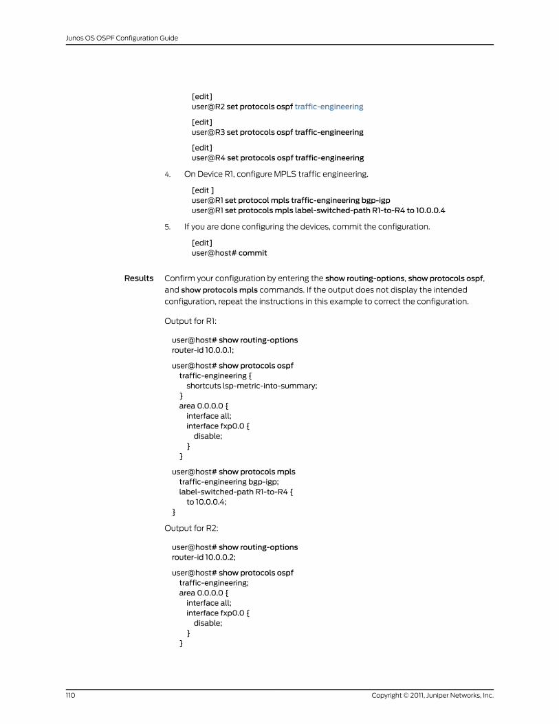
[edit]user@R2 set protocols ospf traffic-engineering
[edit]user@R3 set protocols ospf traffic-engineering
[edit]user@R4 set protocols ospf traffic-engineering
4. On Device R1, configure MPLS traffic engineering.
[edit ]user@R1 set protocol mpls traffic-engineering bgp-igpuser@R1 set protocolsmpls label-switched-path R1-to-R4 to 10.0.0.4
5. If you are done configuring the devices, commit the configuration.
[edit]user@host# commit
Results Confirm your configuration by entering the show routing-options, show protocols ospf,
and show protocolsmpls commands. If the output does not display the intended
configuration, repeat the instructions in this example to correct the configuration.
Output for R1:
user@host# show routing-optionsrouter-id 10.0.0.1;
user@host# show protocols ospftraffic-engineering {shortcuts lsp-metric-into-summary;
}area 0.0.0.0 {interface all;interface fxp0.0 {disable;
}}
user@host# show protocolsmplstraffic-engineering bgp-igp;label-switched-path R1-to-R4 {to 10.0.0.4;
}
Output for R2:
user@host# show routing-optionsrouter-id 10.0.0.2;
user@host# show protocols ospftraffic-engineering;area 0.0.0.0 {interface all;interface fxp0.0 {disable;
}}
Copyright © 2011, Juniper Networks, Inc.110
Junos OS OSPF Configuration Guide
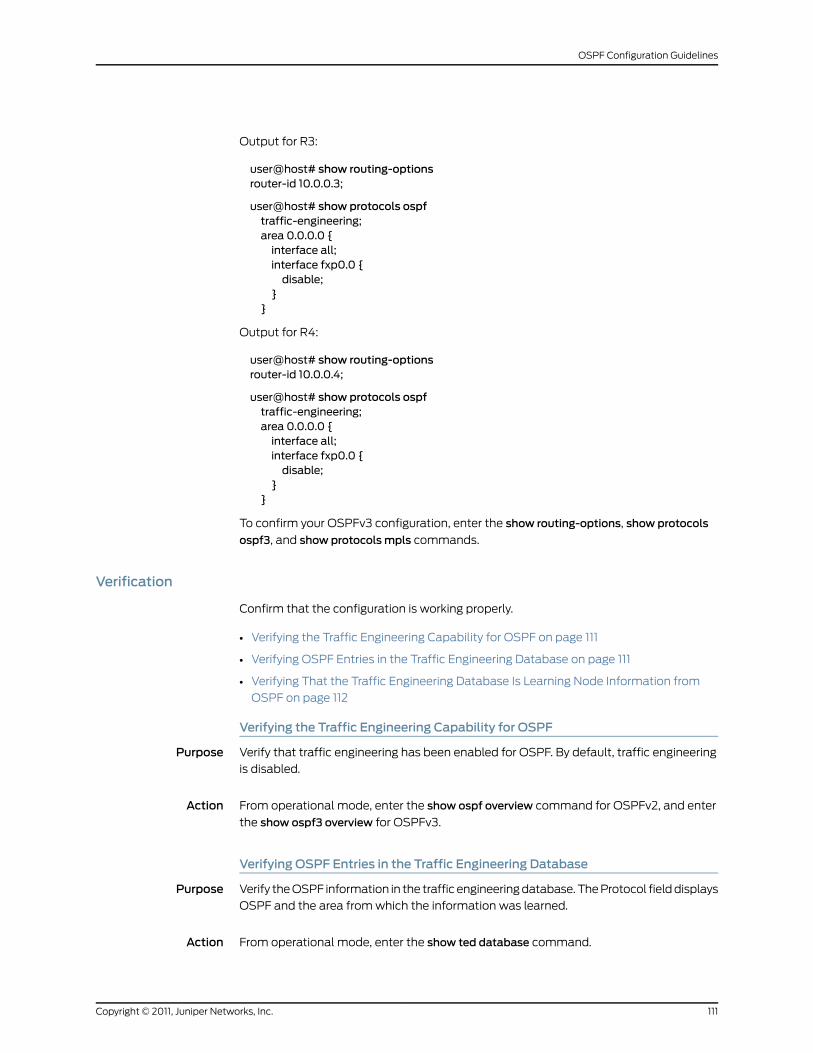
Output for R3:
user@host# show routing-optionsrouter-id 10.0.0.3;
user@host# show protocols ospftraffic-engineering;area 0.0.0.0 {interface all;interface fxp0.0 {disable;
}}
Output for R4:
user@host# show routing-optionsrouter-id 10.0.0.4;
user@host# show protocols ospftraffic-engineering;area 0.0.0.0 {interface all;interface fxp0.0 {disable;
}}
To confirm your OSPFv3 configuration, enter the show routing-options, show protocols
ospf3, and show protocolsmpls commands.
Verification
Confirm that the configuration is working properly.
• Verifying the Traffic Engineering Capability for OSPF on page 111
• Verifying OSPF Entries in the Traffic Engineering Database on page 111
• Verifying That the Traffic Engineering Database Is Learning Node Information from
OSPF on page 112
Verifying the Traffic Engineering Capability for OSPF
Purpose Verify that traffic engineering has been enabled for OSPF. By default, traffic engineering
is disabled.
Action From operational mode, enter the show ospf overview command for OSPFv2, and enter
the show ospf3 overview for OSPFv3.
Verifying OSPF Entries in the Traffic Engineering Database
Purpose Verify the OSPF information in the traffic engineering database. The Protocol field displays
OSPF and the area from which the information was learned.
Action From operational mode, enter the show ted database command.
111Copyright © 2011, Juniper Networks, Inc.
OSPF Configuration Guidelines
Verifying That the Traffic Engineering Database Is Learning Node InformationfromOSPF
Purpose Verify that OSPF is reporting node information. The Protocol name field displays OSPF
and the area from which the information was learned.
Action From operational mode, enter the show ted protocol command.
RelatedDocumentation
OSPF Support for Traffic Engineering•
• Example: Configuring the Traffic Engineering Metric for a Specific OSPF Interface on
page 112
• For more information about traffic engineering, see the Junos OSMPLS Applications
Configuration Guide
Example: Configuring the Traffic EngineeringMetric for a Specific OSPF Interface
This example shows how to configure the OSPF metric value used for traffic engineering.
• Requirements on page 112
• Overview on page 112
• Configuration on page 112
• Verification on page 113
Requirements
Before you begin:
• Configure the device interfaces. See the JunosOSNetwork InterfacesConfigurationGuide.
• Configure OSPF for traffic engineering. See “Example: Enabling OSPF Traffic Engineering
Support” on page 107
Overview
You can configure an OSPF metric that is used exclusively for traffic engineering. To
modify the default value of the traffic engineering metric, include the te-metric statement.
The OSPF traffic engineering metric does not affect normal OSPF forwarding. By default,
the traffic engineering metric is the same value as the OSPF metric. The range is 1 through
65,535.
In this example, you configure the OSPF traffic engineering metric on OSPF interface
fe-0/1/1 in area 0.0.0.0.
Configuration
CLI QuickConfiguration
To quickly configure the OSPF traffic engineering metric for a specific interface, copy the
following command and paste it into the CLI.
Copyright © 2011, Juniper Networks, Inc.112
Junos OS OSPF Configuration Guide
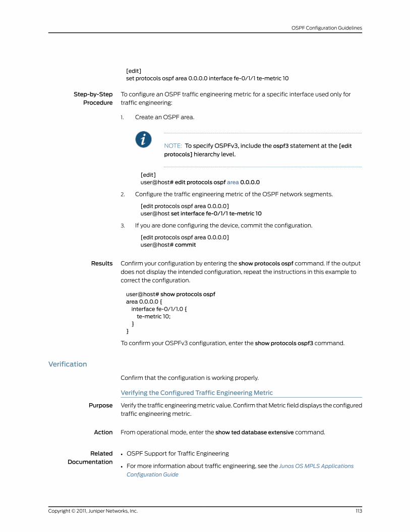
[edit]set protocols ospf area 0.0.0.0 interface fe-0/1/1 te-metric 10
Step-by-StepProcedure
To configure an OSPF traffic engineering metric for a specific interface used only for
traffic engineering:
1. Create an OSPF area.
NOTE: To specify OSPFv3, include the ospf3 statement at the [edit
protocols] hierarchy level.
[edit]user@host# edit protocols ospf area 0.0.0.0
2. Configure the traffic engineering metric of the OSPF network segments.
[edit protocols ospf area 0.0.0.0]user@host set interface fe-0/1/1 te-metric 10
3. If you are done configuring the device, commit the configuration.
[edit protocols ospf area 0.0.0.0]user@host# commit
Results Confirm your configuration by entering the show protocols ospf command. If the output
does not display the intended configuration, repeat the instructions in this example to
correct the configuration.
user@host# show protocols ospfarea 0.0.0.0 {interface fe-0/1/1.0 {te-metric 10;
}}
To confirm your OSPFv3 configuration, enter the show protocols ospf3 command.
Verification
Confirm that the configuration is working properly.
Verifying the Configured Traffic EngineeringMetric
Purpose Verify the traffic engineering metric value. Confirm that Metric field displays the configured
traffic engineering metric.
Action From operational mode, enter the show ted database extensive command.
RelatedDocumentation
OSPF Support for Traffic Engineering•
• For more information about traffic engineering, see the Junos OSMPLS Applications
Configuration Guide
113Copyright © 2011, Juniper Networks, Inc.
OSPF Configuration Guidelines
Applying Policies to OSPF Routes
All routing protocols store the routes that they learn in the routing table. The routing table
uses this collected route information to determine the active routes to destinations. The
routing table then installs the active routes into its forwarding table and also exports
them back into the routing protocols. It is these exported routes that the protocols
advertise.
For each protocol, you control which routes the protocol stores in the routing table and
which routes the routing table exports into the protocol by defining a routing policy for
that protocol. For information about defining a routing policy, see the Junos OS Routing
Policy Configuration Guide.
By default, if a routing device has multiple OSPF areas, learned routes from other areas
are automatically installed into area 0 of the routing table.
To apply routing policies that affect how the routing table exports routes into OSPF,
include the export statement:
export [ policy-names ];
For a list of hierarchy levels at which you can include this statement, see the statement
summary section for this statement.
OSPF import policy allows users to define policy to prevent adding OSPF routes to the
routing table. This filtering happens when OSPF installs the route in the routing table.
You can filter the routes, but not LSA flooding. The import policy can filter on any attribute
of the OSPF route.
To filter OSPF routes from being added to the routing table, include the import statement:
import [ policy-names ];
For a list of hierarchy levels at which you can include this statement, see the statement
summary section for this statement.
Configuring Import and Export Policies for Network Summaries
By default, OSPF uses network-summary link-state advertisements (LSAs) to transmit
route information across area boundaries. Each area border router (ABR) floods
network-summary LSAs to other routing devices in the same area. In Junos OS Release 9.1
and later, you can configure export and import policies for OSPFv2 and OSPFv3 that
enable you to control how network-summary LSAs, which contain information about
interarea OSPF prefixes, are distributed and generated. For OSPFv3, the LSA is referred
to as the interarea prefix LSA and performs the same function as a network-summary
LSA performs for OSPFv2. An ABR originates an interarea prefix LSA for each IPv6 prefix
that must be advertised into an area.
The export policy enables you to specify which summary LSAs are flooded into an area.
The import policy enables you to control which routes learned from an area are used to
generate summary LSAs into other areas. You define a routing policy at the [edit
policy-options policy-statement policy-name] hierarchy level. As with all OSPF export
Copyright © 2011, Juniper Networks, Inc.114
Junos OS OSPF Configuration Guide
policies, the default for network-summary LSA export policies is to reject everything.
Similarly, as with all OSPF import policies, the default for network-summary LSA import
policies is to accept all OSPF routes. For more information about configuring policies,
see the Junos OS Routing Policy Configuration Guide.
To apply an export routing policy for OSPFv2 that affects which network-summary LSAs
are flooded into an area, include thenetwork-summary-export [policy-names ] statement:
area area-id {network-summary-export [ policy-names ];
}
For a list of hierarchy levels at which you can include this statement, see the statement
summary section for this statement.
To apply an import routing policy for OSPFv2 that affects which routes learned from an
area are used to generate network-summary LSAs, include thenetwork-summary-import
[ policy-names] statement:
area area-id {network-summary-import [ policy-names ];
}
For a list of hierarchy levels at which you can include this statement, see the statement
summary section for this statement.
To apply an export routing policy for OSPFv3 that affects which interarea prefix LSAs
are flooded into an area, include the inter-area-prefix-export [ policy-names ] statement:
area area-id {inter-area-prefix-export [ policy-names ];
}
For a list of hierarchy levels at which you can include this statement, see the statement
summary section for this statement.
To apply an import routing policy for OSPFv3 that affects which routes learned from an
area are used to generate interarea prefix LSAs, include the inter-area-prefix-import [
policy-names ] statement:
area area-id {inter-area-prefix-import [ policy-names ];
}
For a list of hierarchy levels at which you can include this statement, see the statement
summary section for this statement.
Configuring Priority for Prefixes in Import Policy
In a network with a large number of OSPF routes, it can be useful to control the order in
which routes are updated in response to a network topology change. In Junos OS
Release 9.3 and later, you can specify a priority of high, medium, or low for prefixes
included in an OSPF import policy. In the event of an OSPF topology change, high-priority
prefixes are updated in the routing table first, followed by medium and then low-priority
prefixes.
115Copyright © 2011, Juniper Networks, Inc.
OSPF Configuration Guidelines
OSPF import policy can only be used to set priority or to filter OSPF external routes. If an
OSPF import policy is applied that results in a reject terminating action for a nonexternal
route, then the reject action is ignored and the route is accepted anyway. By default, such
a route is now installed in the routing table with a priority of low. This behavior prevents
traffic black holes, that is, silently discarded traffic, by ensuring consistent routing within
the OSPF domain.
In general, OSPF routes that are not explicitly assigned a priority are treated as priority
medium, except for the following:
• Summary discard routes have a default priority of low.
• Local routes that are not added to the routing table are assigned a priority of low.
• External routes that are rejected by an import policy and thus are not added to the
routing table are assigned a priority of low.
To specify a priority for prefixes included in an import policy, include the priority (high |
medium | low) statement at the [edit policy-options policy statement
policy-statement-name term term-name then] or [edit policy-options policy-statement
policy-statement-name then] hierarchy level.
Any available match criteria applicable to OSPF routes can be used to determine the
priority. Two of the most commonly used match criteria for OSPF are the route-filter and
tag statements. For more information about configuring routing policy and match
conditions, see the Junos OS Routing Policy Configuration Guide.
Example: Configuring a Route Filter Policy to Specify Priority for Prefixes Learned ThroughOSPF
Configure an import routing policy, ospf-import, that enables you to specify a priority for
specific prefixes learned through OSPF. Routes associated with these prefixes are installed
in the routing table in the order of the prefixes’ specified priority. Routes matching
200.3.0.0/16 orlonger are installed first because they have a priority of high. Routes
matching200.2.0.0/16orlongerare installed next because they have a priority ofmedium.
Routes matching 200.1.0.0/16 orlonger are installed last because they have a priority of
low. To apply the import policy to OSPF, include the import ospf-import statement at the
[edit protocols (ospf | ospf3)] hierarchy level. For a complete list of hierarchy levels at
which the import statement can be configured, see the configuration statement summary
for that statement.
policy-options {policy-statement ospf-import {term t1 {from {route-filter 200.1.0.0/16 orlonger;
}then {priority low;accept;
}}term t2 {
Copyright © 2011, Juniper Networks, Inc.116
Junos OS OSPF Configuration Guide
from {route-filter 200.2.0.0/16 orlonger;
}then {priority medium {accept;
}}term t3 {from {route-filter 200.3.0.0/16 orlonger;
}then {priority high;accept;
}}
}}
Configuring OSPF Routing Table Groups
To install routes learned from OSPF routing instances into routing tables in the OSPF
routing table group, include the rib-group statement:
rib-group group-name;
For a list of hierarchy levels at which you can include this statement, see the statement
summary section for this statement.
Example: Configuring OSPFv2 Sham Links
This example shows how to enable OSPFv2 sham links on a PE routing device.
• Requirements on page 117
• Overview on page 118
• Configuration on page 119
• Verification on page 122
Requirements
Before you begin:
• Configure the device interfaces. See the JunosOSNetwork InterfacesConfigurationGuide.
• Configure the Layer 3 VPN per your network requirements. See the Junos OS VPNs
Configuration Guide.
• Configure the VPN import and VPN export policies per your network requirements. See
the Junos OS VPNs Configuration Guide.
117Copyright © 2011, Juniper Networks, Inc.
OSPF Configuration Guidelines
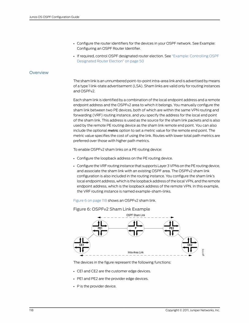
• Configure the router identifiers for the devices in your OSPF network. See Example:
Configuring an OSPF Router Identifier.
• If required, control OSPF designated router election. See “Example: Controlling OSPF
Designated Router Election” on page 50
Overview
The sham link is an unnumbered point-to-point intra-area link and is advertised by means
of a type 1 link-state advertisement (LSA). Sham links are valid only for routing instances
and OSPFv2.
Each sham link is identified by a combination of the local endpoint address and a remote
endpoint address and the OSPFv2 area to which it belongs. You manually configure the
sham link between two PE devices, both of which are within the same VPN routing and
forwarding (VRF) routing instance, and you specify the address for the local end point
of the sham link. This address is used as the source for the sham link packets and is also
used by the remote PE routing device as the sham link remote end point. You can also
include the optional metric option to set a metric value for the remote end point. The
metric value specifies the cost of using the link. Routes with lower total path metrics are
preferred over those with higher path metrics.
To enable OSPFv2 sham links on a PE routing device:
• Configure the loopback address on the PE routing device.
• Configure the VRF routing instance that supports Layer 3 VPNs on the PE routing device,
and associate the sham link with an existing OSPF area. The OSPFv2 sham link
configuration is also included in the routing instance. You configure the sham link’s
local endpoint address, which is the loopback address of the local VPN, and the remote
endpoint address, which is the loopback address of the remote VPN. In this example,
the VRF routing instance is named example-sham-links.
Figure 6 on page 118 shows an OSPFv2 sham link.
Figure 6: OSPFv2 Sham Link Example
The devices in the figure represent the following functions:
• CE1 and CE2 are the customer edge devices.
• PE1 and PE2 are the provider edge devices.
• P is the provider device.
Copyright © 2011, Juniper Networks, Inc.118
Junos OS OSPF Configuration Guide
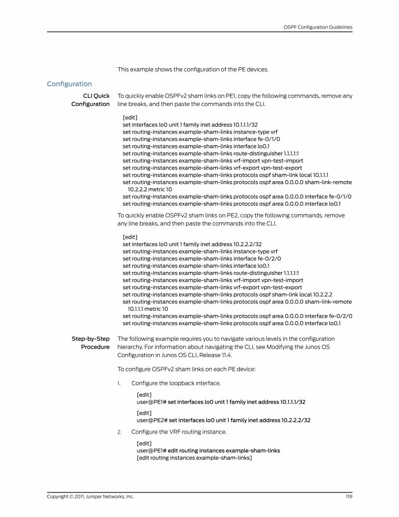
This example shows the configuration of the PE devices.
Configuration
CLI QuickConfiguration
To quickly enable OSPFv2 sham links on PE1, copy the following commands, remove any
line breaks, and then paste the commands into the CLI.
[edit]set interfaces lo0 unit 1 family inet address 10.1.1.1/32set routing-instances example-sham-links instance-type vrfset routing-instances example-sham-links interface fe-0/1/0set routing-instances example-sham-links interface lo0.1set routing-instances example-sham-links route-distinguisher 1.1.1.1:1set routing-instances example-sham-links vrf-import vpn-test-importset routing-instances example-sham-links vrf-export vpn-test-exportset routing-instances example-sham-links protocols ospf sham-link local 10.1.1.1set routing-instances example-sham-links protocols ospf area 0.0.0.0 sham-link-remote10.2.2.2 metric 10
set routing-instances example-sham-links protocols ospf area 0.0.0.0 interface fe-0/1/0set routing-instances example-sham-links protocols ospf area 0.0.0.0 interface lo0.1
To quickly enable OSPFv2 sham links on PE2, copy the following commands, remove
any line breaks, and then paste the commands into the CLI.
[edit]set interfaces lo0 unit 1 family inet address 10.2.2.2/32set routing-instances example-sham-links instance-type vrfset routing-instances example-sham-links interface fe-0/2/0set routing-instances example-sham-links interface lo0.1set routing-instances example-sham-links route-distinguisher 1.1.1.1:1set routing-instances example-sham-links vrf-import vpn-test-importset routing-instances example-sham-links vrf-export vpn-test-exportset routing-instances example-sham-links protocols ospf sham-link local 10.2.2.2set routing-instances example-sham-links protocols ospf area 0.0.0.0 sham-link-remote10.1.1.1 metric 10
set routing-instances example-sham-links protocols ospf area 0.0.0.0 interface fe-0/2/0set routing-instances example-sham-links protocols ospf area 0.0.0.0 interface lo0.1
Step-by-StepProcedure
The following example requires you to navigate various levels in the configuration
hierarchy. For information about navigating the CLI, see Modifying the Junos OS
Configuration in Junos OS CLI, Release 11.4.
To configure OSPFv2 sham links on each PE device:
1. Configure the loopback interface.
[edit]user@PE1# set interfaces lo0 unit 1 family inet address 10.1.1.1/32
[edit]user@PE2# set interfaces lo0 unit 1 family inet address 10.2.2.2/32
2. Configure the VRF routing instance.
[edit]user@PE1# edit routing instances example-sham-links[edit routing instances example-sham-links]
119Copyright © 2011, Juniper Networks, Inc.
OSPF Configuration Guidelines
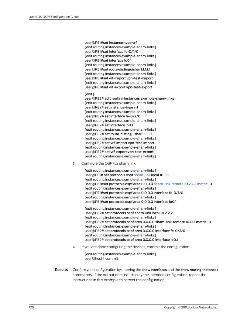
user@PE1#set instance-type vrf[edit routing instances example-sham-links]user@PE1#set interface fe-0/1/0[edit routing instances example-sham-links]user@PE1#set interface lo0.1[edit routing instances example-sham-links]user@PE1#set route-distinguisher 1.1.1.1:1[edit routing instances example-sham-links]user@PE1#set vrf-import vpn-test-import[edit routing instances example-sham-links]user@PE1#set vrf-export vpn-test-export
[edit]user@PE2# edit routing instances example-sham-links[edit routing instances example-sham-links]user@PE2# set instance-type vrf[edit routing instances example-sham-links]user@PE2# set interface fe-0/2/0[edit routing instances example-sham-links]user@PE2# set interface lo0.1[edit routing instances example-sham-links]user@PE2# set route-distinguisher 1.1.1.1:1[edit routing instances example-sham-links]user@PE2# set vrf-import vpn-test-import[edit routing instances example-sham-links]user@PE2# set vrf-export vpn-test-export[edit routing instances example-sham-links]
3. Configure the OSPFv2 sham link.
[edit routing instances example-sham-links]user@PE1# set protocols ospf sham-link local 10.1.1.1[edit routing instances example-sham-links]user@PE1#set protocols ospf area 0.0.0.0 sham-link-remote 10.2.2.2metric 10[edit routing instances example-sham-links]user@PE1#set protocols ospf area 0.0.0.0 interface fe-0/1/0[edit routing instances example-sham-links]user@PE1#set protocols ospf area 0.0.0.0 interface lo0.1
[edit routing instances example-sham-links]user@PE2# set protocols ospf sham-link local 10.2.2.2[edit routing instances example-sham-links]user@PE2# set protocols ospf area 0.0.0.0 sham-link-remote 10.1.1.1 metric 10[edit routing instances example-sham-links]user@PE2# set protocols ospf area 0.0.0.0 interface fe-0/2/0[edit routing instances example-sham-links]user@PE2# set protocols ospf area 0.0.0.0 interface lo0.1
4. If you are done configuring the devices, commit the configuration.
[edit routing instances example-sham-links]user@host# commit
Results Confirm your configuration by entering the showinterfacesand the showrouting-instances
commands. If the output does not display the intended configuration, repeat the
instructions in this example to correct the configuration.
Copyright © 2011, Juniper Networks, Inc.120
Junos OS OSPF Configuration Guide
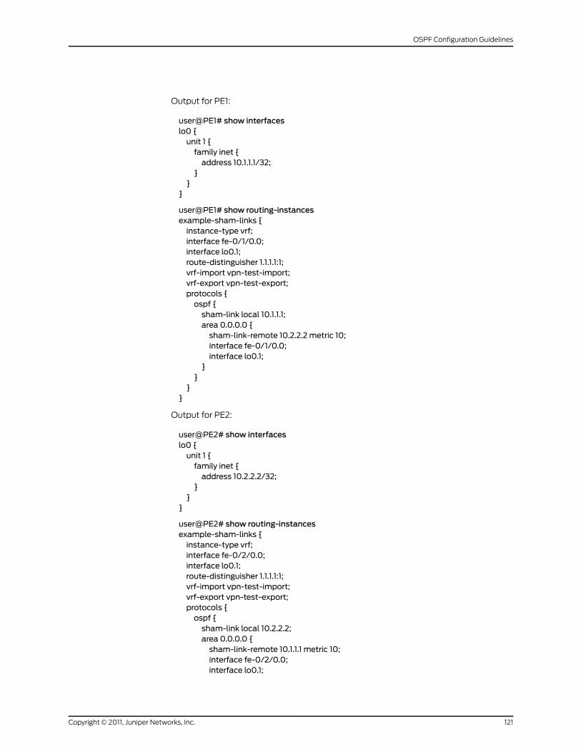
Output for PE1:
user@PE1# show interfaceslo0 {unit 1 {family inet {address 10.1.1.1/32;
}}
}
user@PE1# show routing-instancesexample-sham-links {instance-type vrf;interface fe-0/1/0.0;interface lo0.1;route-distinguisher 1.1.1.1:1;vrf-import vpn-test-import;vrf-export vpn-test-export;protocols {ospf {sham-link local 10.1.1.1;area 0.0.0.0 {sham-link-remote 10.2.2.2 metric 10;interface fe-0/1/0.0;interface lo0.1;
}}
}}
Output for PE2:
user@PE2# show interfaceslo0 {unit 1 {family inet {address 10.2.2.2/32;
}}
}
user@PE2# show routing-instancesexample-sham-links {instance-type vrf;interface fe-0/2/0.0;interface lo0.1;route-distinguisher 1.1.1.1:1;vrf-import vpn-test-import;vrf-export vpn-test-export;protocols {ospf {sham-link local 10.2.2.2;area 0.0.0.0 {sham-link-remote 10.1.1.1 metric 10;interface fe-0/2/0.0;interface lo0.1;
121Copyright © 2011, Juniper Networks, Inc.
OSPF Configuration Guidelines
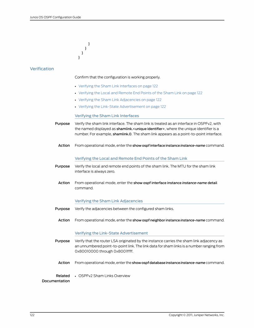
}}
}}
Verification
Confirm that the configuration is working properly.
• Verifying the Sham Link Interfaces on page 122
• Verifying the Local and Remote End Points of the Sham Link on page 122
• Verifying the Sham Link Adjacencies on page 122
• Verifying the Link-State Advertisement on page 122
Verifying the Sham Link Interfaces
Purpose Verify the sham link interface. The sham link is treated as an interface in OSPFv2, with
the named displayed as shamlink.<unique identifier>, where the unique identifier is a
number. For example, shamlink.0. The sham link appears as a point-to-point interface.
Action From operational mode, enter the showospf interface instance instance-name command.
Verifying the Local and Remote End Points of the Sham Link
Purpose Verify the local and remote end points of the sham link. The MTU for the sham link
interface is always zero.
Action From operational mode, enter the show ospf interface instance instance-name detail
command.
Verifying the Sham Link Adjacencies
Purpose Verify the adjacencies between the configured sham links.
Action From operational mode, enter the showospfneighbor instance instance-name command.
Verifying the Link-State Advertisement
Purpose Verify that the router LSA originated by the instance carries the sham link adjacency as
an unnumbered point-to-point link. The link data for sham links is a number ranging from
0x80010000 through 0x8001ffff.
Action From operational mode, enter theshowospfdatabase instance instance-namecommand.
RelatedDocumentation
OSPFv2 Sham Links Overview•
Copyright © 2011, Juniper Networks, Inc.122
Junos OS OSPF Configuration Guide
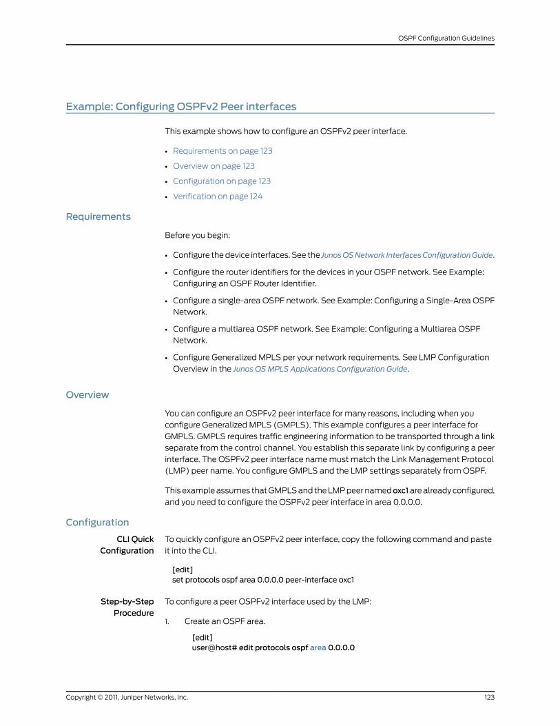
Example: Configuring OSPFv2 Peer interfaces
This example shows how to configure an OSPFv2 peer interface.
• Requirements on page 123
• Overview on page 123
• Configuration on page 123
• Verification on page 124
Requirements
Before you begin:
• Configure the device interfaces. See the JunosOSNetwork InterfacesConfigurationGuide.
• Configure the router identifiers for the devices in your OSPF network. See Example:
Configuring an OSPF Router Identifier.
• Configure a single-area OSPF network. See Example: Configuring a Single-Area OSPF
Network.
• Configure a multiarea OSPF network. See Example: Configuring a Multiarea OSPF
Network.
• Configure Generalized MPLS per your network requirements. See LMP Configuration
Overview in the Junos OSMPLS Applications Configuration Guide.
Overview
You can configure an OSPFv2 peer interface for many reasons, including when you
configure Generalized MPLS (GMPLS). This example configures a peer interface for
GMPLS. GMPLS requires traffic engineering information to be transported through a link
separate from the control channel. You establish this separate link by configuring a peer
interface. The OSPFv2 peer interface name must match the Link Management Protocol
(LMP) peer name. You configure GMPLS and the LMP settings separately from OSPF.
This example assumes that GMPLS and the LMP peer namedoxc1are already configured,
and you need to configure the OSPFv2 peer interface in area 0.0.0.0.
Configuration
CLI QuickConfiguration
To quickly configure an OSPFv2 peer interface, copy the following command and paste
it into the CLI.
[edit]set protocols ospf area 0.0.0.0 peer-interface oxc1
Step-by-StepProcedure
To configure a peer OSPFv2 interface used by the LMP:
Create an OSPF area.1.
[edit]user@host# edit protocols ospf area 0.0.0.0
123Copyright © 2011, Juniper Networks, Inc.
OSPF Configuration Guidelines
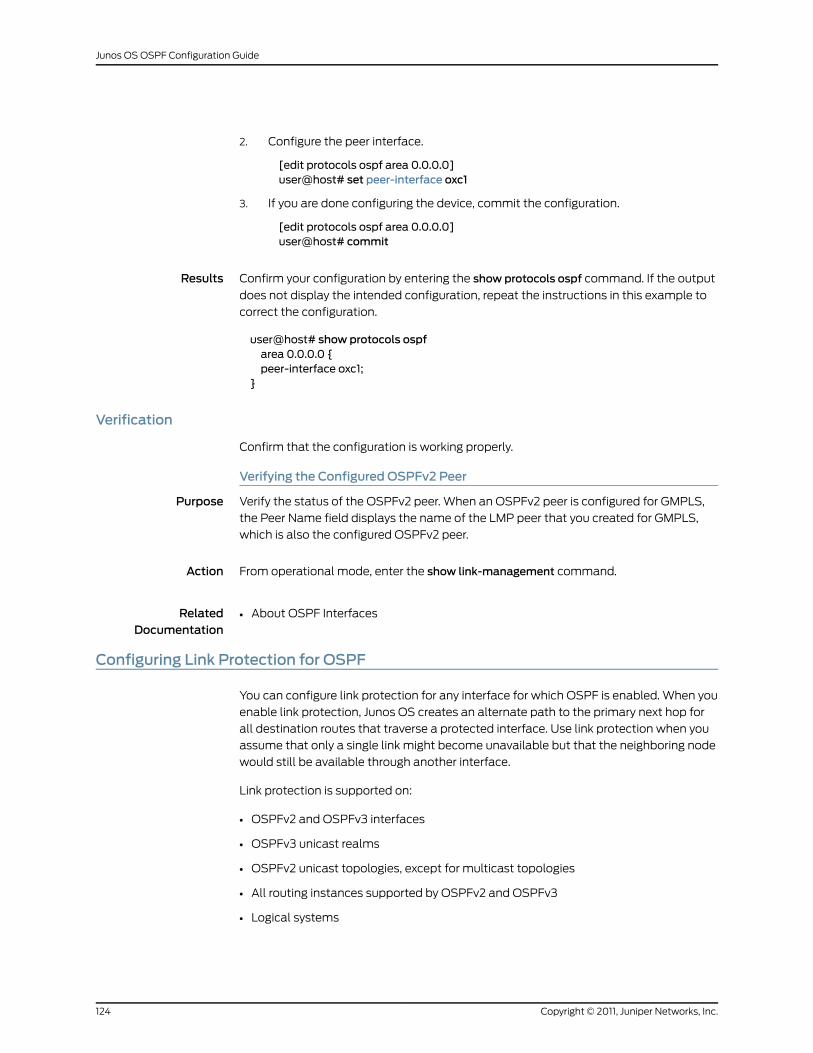
2. Configure the peer interface.
[edit protocols ospf area 0.0.0.0]user@host# set peer-interface oxc1
3. If you are done configuring the device, commit the configuration.
[edit protocols ospf area 0.0.0.0]user@host# commit
Results Confirm your configuration by entering the show protocols ospf command. If the output
does not display the intended configuration, repeat the instructions in this example to
correct the configuration.
user@host# show protocols ospfarea 0.0.0.0 {peer-interface oxc1;
}
Verification
Confirm that the configuration is working properly.
Verifying the Configured OSPFv2 Peer
Purpose Verify the status of the OSPFv2 peer. When an OSPFv2 peer is configured for GMPLS,
the Peer Name field displays the name of the LMP peer that you created for GMPLS,
which is also the configured OSPFv2 peer.
Action From operational mode, enter the show link-management command.
RelatedDocumentation
About OSPF Interfaces•
Configuring Link Protection for OSPF
You can configure link protection for any interface for which OSPF is enabled. When you
enable link protection, Junos OS creates an alternate path to the primary next hop for
all destination routes that traverse a protected interface. Use link protection when you
assume that only a single link might become unavailable but that the neighboring node
would still be available through another interface.
Link protection is supported on:
• OSPFv2 and OSPFv3 interfaces
• OSPFv3 unicast realms
• OSPFv2 unicast topologies, except for multicast topologies
• All routing instances supported by OSPFv2 and OSPFv3
• Logical systems
Copyright © 2011, Juniper Networks, Inc.124
Junos OS OSPF Configuration Guide
To configure link protection for an OSPF interface:
• Include the link-protection statement at the [edit protocols (ospf | ospf3) area area-id
interface interface-name] hierarchy level.
BEST PRACTICE: When you configure link protection for OSPF, youmustalso configure a per-packet load-balancing routing policy to ensure that therouting protocol process installs all the next hops for a given route in therouting table.
In the following example, the OSPF interface so-0/0/0.0 in area 0.0.0.0 is configured
for link protection. If a link for a destination route that traverses this interface becomes
unavailable, Junos OS creates a loop-free backup path through another interface on the
neighboring node, thus avoiding the link that is no longer available.
[edit]protocols {ospf {area 0.0.0.0 {interface so-0/0/0.0 {link-protection;
}}
}}
RelatedDocumentation
Loop-Free Alternate Routes for OSPF Overview on page 19•
• link-protection on page 176
Configuring Node-Link Protection for OSPF
You can configure node-link protection on any interface for which OSPF is enabled.
Node-link protection establishes an alternative path through a different routing device
altogether for all destination routes that traverse a protected interface. Node-link
protection assumes that the entire routing device, or node, has failed. Junos OS therefore
calculates a backup path that avoids the primary next-hop routing device.
Node-link protection is supported on:
• OSPFv2 and OSPFv3 interfaces
• OSPFv3 unicast realms
• OSPFv2 unicast topologies
• All routing instances supported by OSPFv2 and OSPFv3
• Logical systems
125Copyright © 2011, Juniper Networks, Inc.
OSPF Configuration Guidelines
To configure node-link protection for an OSPF interface:
• Include the node-link-protection statement at the [edit protocols (ospf | ospf3) area
area-id interface interface-name] hierarchy level.
BEST PRACTICE: Youmust also configure a per-packet load-balancingrouting policy to ensure that the routing protocol process installs all the nexthops for a given route in the routing table.
In the following example, the OSPF interface so-0/0/0.0 in area 0.0.0.0 is configured
for node-link protection. If a link for a destination route that traverses this interface
becomes unavailable, Junos OS creates a loop-free backup path through a different
routing device altogether, thus avoiding the primary next-hop routing device.
[edit]protocols {ospf {area 0.0.0.0 {interface so-0/0/0.0 {node-link-protection;
}}
}}
RelatedDocumentation
Loop-Free Alternate Routes for OSPF Overview on page 19•
• node-link-protection on page 189
Excluding an OSPF Interface as a Backup for a Protected Interface
By default, all OSPF interfaces that belong to the default instance or to a specific routing
instance are eligible as a backup interface for interfaces configured with link-protection
or node-link protection. You can specify that any OSPF interface be excluded from
functioning as a backup interface to protected interfaces.
To exclude an OSPF interface as a backup interface for a protected interface:
• Include the no-eligible-backup statement at the [edit protocols (ospf | ospf3) area
area-id interface interface-name] hierarchy level.
In the following example, interface so-0/0/0.0 has been configured to prohibit backup
traffic for traffic destined for a protected interface. This means that if a neighboring
next-hop path or node for a protected interface fails, interface so-0/0/0.0 cannot be
used to transmit traffic to a backup path.
[edit]protocols {ospf {area 0.0.0.0 {interface so-0/0/0.0 {
Copyright © 2011, Juniper Networks, Inc.126
Junos OS OSPF Configuration Guide
no-eligible-backup;}
}}
}
RelatedDocumentation
Loop-Free Alternate Routes for OSPF Overview on page 19•
• Configuring Link Protection for OSPF on page 124
• Configuring Node-Link Protection for OSPF on page 125
• no-eligible-backup on page 185
Configuring Backup SPFOptions for Protected OSPF Interfaces
By default, if at least one OSPF interface is configured for link-protection or node-link
protection, Junos OS calculates backup next hops for all the topologies in an OSPF
instance. You can configure the following backup shortest-path-first (SPF) options to
override the default behavior:
• Disable the calculation of backup next hops for an OSPF instance or a specific topology
in an instance.
• Prevent the installation of backup next hops in the routing table or the forwarding table
for an OSPF instance or a specific topology in an instance.
• Limit the calculation of backup next hops to a subset of paths as defined in RFC 5286,
Basic Specification for IP Fast Reroute: Loop-Free Alternates.
You can disable the backup SPF algorithm for an OSPF instance or specific topology in
an instance. Doing so prevents the calculation of backup next hops for that OSPF instance
or topology.
To disable the calculation of backup next hops for an OSPF instance or topology:
• Include the disable statement at the [edit protocols (ospf | ospf3) backup-spf-options]
or [edit protocols ospf backup-spf-options topology topology-name] hierarchy level.
In the following example, the calculation of backup next hops is disabled for the OSPF
topology voice:
[edit]protocols {ospf {topology voice {backup-spf-options {disable;
}}
}}
You can configure the routing device to prevent the installation of backup next hops in
the routing table or the forwarding table for an OSPF instance, or a specific topology in
127Copyright © 2011, Juniper Networks, Inc.
OSPF Configuration Guidelines
an OSPF instance. The SPF algorithm continues to calculate backup next hops, but they
are not installed.
To prevent the routing device from installing backup next hops in the routing table or the
forwarding table:
• Include theno-install statement at the [editprotocols(ospf |ospf3)backup-spf-options]
or the [edit protocols ospf topology topology-name] hierarchy level.
In the following example, backup next hops for the OSPF topology voice are not installed
in the routing table or forwarding table. Any calculated backup next hops for other OSPF
instances or topologies continue to be installed.
[edit]protocols {ospf {topology voice {backup-spf-options {no-install;
}}
}}
You can limit the calculation of backup next hops to downstream paths, as defined in
RFC 5286. You can specify for Junos OS to use only downstream paths as backup next
hops for protected interfaces for an OSPF instance or a specific topology in an OSPF
instance. In a downstream path, the distance from the backup neighbor to the destination
must be smaller than the distance from the calculating routing device to the destination.
Using only downstream paths as loop-free alternate paths for protected interfaces
ensures that these paths do not result in microloops. However, you might experience less
than optimal backup coverage for your network.
To limit the calculation of backup next hops to downstream paths:
• Include the downstream-paths-only statement at the [edit protocols (ospf | ospf3)
backup-spf-options]or [editprotocolsospfbackup-spf-optionstopology topology-name]
hierarchy level.
In the following example, only downstream paths are calculated as backup next hops
for the topology voice:
[edit]protocols {ospf {topology voice {backup-spf-options {downstream-paths-only;
}}
}}
Copyright © 2011, Juniper Networks, Inc.128
Junos OS OSPF Configuration Guide
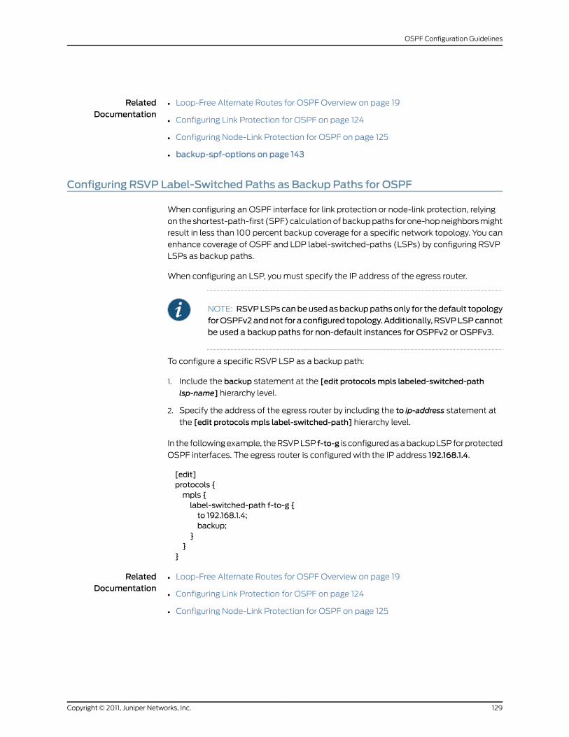
RelatedDocumentation
Loop-Free Alternate Routes for OSPF Overview on page 19•
• Configuring Link Protection for OSPF on page 124
• Configuring Node-Link Protection for OSPF on page 125
• backup-spf-options on page 143
Configuring RSVP Label-Switched Paths as Backup Paths for OSPF
When configuring an OSPF interface for link protection or node-link protection, relying
on the shortest-path-first (SPF) calculation of backup paths for one-hop neighbors might
result in less than 100 percent backup coverage for a specific network topology. You can
enhance coverage of OSPF and LDP label-switched-paths (LSPs) by configuring RSVP
LSPs as backup paths.
When configuring an LSP, you must specify the IP address of the egress router.
NOTE: RSVPLSPscanbeusedasbackuppathsonly for thedefault topologyforOSPFv2andnot for aconfigured topology.Additionally, RSVPLSPcannotbe used a backup paths for non-default instances for OSPFv2 or OSPFv3.
To configure a specific RSVP LSP as a backup path:
1. Include the backup statement at the [edit protocolsmpls labeled-switched-path
lsp-name] hierarchy level.
2. Specify the address of the egress router by including the to ip-address statement at
the [edit protocolsmpls label-switched-path] hierarchy level.
In the following example, the RSVP LSP f-to-g is configured as a backup LSP for protected
OSPF interfaces. The egress router is configured with the IP address 192.168.1.4.
[edit]protocols {mpls {label-switched-path f-to-g {to 192.168.1.4;backup;
}}
}
RelatedDocumentation
Loop-Free Alternate Routes for OSPF Overview on page 19•
• Configuring Link Protection for OSPF on page 124
• Configuring Node-Link Protection for OSPF on page 125
129Copyright © 2011, Juniper Networks, Inc.
OSPF Configuration Guidelines
Example: Tracing OSPF Protocol Traffic
This example shows how to trace OSPF protocol traffic.
• Requirements on page 130
• Overview on page 130
• Configuration on page 131
• Verification on page 134
Requirements
This example assumes that OSPF is properly configured and running in your network,
and you want to trace OSPF protocol traffic for debugging purposes.
Overview
You can trace OSPF protocol traffic to help debug OSPF protocol issues. When you trace
OSPF protocol traffic, you specify the name of the file and the type of information you
want to trace. All files are placed in a directory on the routing device’s hard disk. On M
Series and T Series routers, trace files are stored in the /var/log directory.
This example shows a few configurations that might be useful when debugging OSPF
protocol issues. The verification output displayed is specific to each configuration.
TIP: Tokeep trackof your log files, createameaningful anddescriptive nameso it is easy to remember the content of the trace file. We recommend thatyou place global routing protocol tracing output in the file routing-log, and
OSPF tracing output in the file ospf-log.
In the first example, you globally enable tracing operations for all routing protocols that
are actively running on your routing device to the file routing-log. With this configuration,
you keep the default settings for the trace file size and the number of trace files. After
enabling global tracing operations, you enable tracing operations to provide detailed
information about OSPF packets, including link-state advertisements, requests, and
updates, database description packets, and hello packets to the file ospf-log, and you
configure the following options:
• size—Specifies the maximum size of each trace file, in KB, MB, or GB. In this example,
you configure 10 KB as the maximum size. When the file reaches its maximum size, it
is renamed with a .0 extension. When the file again reaches its maximum size, it is
renamed with a .1 extension, and the newly created file is renamed with a .0 extension.
This renaming scheme continues until the maximum number of trace files is reached.
Then, the oldest trace file is overwritten. If you specify a maximum file size, you must
also specify a maximum number of trace files with the files option. You specify k for
KB, m for MB, and g for GB. By default, the trace file size is 128 KB. The file size range
is 10 KB through the maximum file size supported on your system.
Copyright © 2011, Juniper Networks, Inc.130
Junos OS OSPF Configuration Guide
• files—Specifies the maximum number of trace files. In this example, you configure a
maximum of 5 trace files. When a trace file reaches its maximum size, it is renamed
with a .0 extension, then a .1 extension, and so on until the maximum number of trace
files is reached. When the maximum number of files is reached, the oldest trace file is
overwritten. If you specify a maximum number of files, you must also specify a maximum
file size with the size option. By default, there are 10 files. The range is 2 through 1000
files.
In the second example, you trace all SPF calculations to the file ospf-log by including
the spf flag. You keep the default settings for the trace file size and the number of trace
files.
In the third example, you trace the creation, receipt, and retransmission of all LSAs to
the file ospf-log by including the lsa-request, lsa-update, and lsa-ack flags. You keep the
default settings for the trace file size and the number of trace files.
Configuration
• Configuring Global Tracing Operations and Tracing OSPF Packet Information on page 131
• Tracing SPF Calculations on page 133
• Tracing Link-State Advertisements on page 133
Configuring Global Tracing Operations and Tracing OSPF Packet Information
CLI QuickConfiguration
To quickly enable global tracing operations for all routing protocols actively running on
your routing device and to trace detailed information about OSPF packets, copy the
following commands and paste them into the CLI.
[edit]set routing-options traceoptions file routing-logset protocols ospf traceoptions file ospf-logset protocols ospf traceoptions file files 5 size 10kset protocols ospf traceoptions flag lsa-ackset protocols ospf traceoptions flag database-descriptionset protocols ospf traceoptions flag helloset protocols ospf traceoptions flag lsa-updateset protocols ospf traceoptions flag lsa-request
Step-by-StepProcedure
The following example requires you to navigate various levels in the configuration
hierarchy. For information about navigating the CLI, see Modifying the Junos OS
Configuration in Junos OS CLI, Release 11.4.
To configure global routing tracing operations and tracing operations for OSPF packets:
1. Configure tracing at the routing options level to collect information about the active
routing protocols on your routing device.
[edit]user@host# edit routing-options traceoptions
2. Configure the filename for the global trace file.
[edit routing-options traceoptions]user@host# set file routing-log
131Copyright © 2011, Juniper Networks, Inc.
OSPF Configuration Guidelines
3. Configure the filename for the OSPF trace file.
NOTE: To specify OSPFv3, include the ospf3 statement at the [edit
protocols] hierarchy level.
[edit]user@host# edit protocols ospf traceoptionsuser@host# set file ospf-log
4. Configure the maximum number of trace files.
[edit protocols ospf traceoptions]user@host# set file files 5
5. Configure the maximum size of each trace file.
[edit protocols ospf traceoptions]user@host# set file size 10k
6. Configure tracing flags.
[edit protocols ospf traceoptions]user@host# set flag lsa-ackuser@host# set flag database-descriptionuser@host# set flag hellouser@host# set flag lsa-updateuser@host# set flag lsa-request
7. If you are done configuring the device, commit the configuration.
[edit protocols ospf traceoptions]user@host# commit
Results Confirm your configuration by entering the show routing-options and the show protocols
ospf commands. If the output does not display the intended configuration, repeat the
instructions in this example to correct the configuration.
user@host# show routing-optionstraceoptions {file routing-log;
}
user@host# show protocols ospftraceoptions {file ospf-log size 10k files 5;flag lsa-ack;flag database-description;flag hello;flag lsa-update;flag lsa-request;
}
To confirm your OSPFv3 configuration, enter the show routing-options and the show
protocols ospf3 commands.
Copyright © 2011, Juniper Networks, Inc.132
Junos OS OSPF Configuration Guide
Tracing SPF Calculations
CLI QuickConfiguration
To quickly trace SPF calculations, copy the following commands and paste them into
the CLI.
[edit]set protocols ospf traceoptions file ospf-logset protocols ospf traceoptions flag spf
Step-by-StepProcedure
To configure SPF tracing operations for OSPF:
Configure the filename for the OSPF trace file.1.
NOTE: To specify OSPFv3, include the ospf3 statement at the [edit
protocols] hierarchy level.
[edit]user@host# edit protocols ospf traceoptionsuser@host# set file ospf-log
2. Configure the SPF tracing flag.
[edit protocols ospf traceoptions]user@host# set flag spf
3. If you are done configuring the device, commit the configuration.
[edit protocols ospf traceoptions]user@host# commit
Results Confirm your configuration by entering the show protocols ospf command. If the output
does not display the intended configuration, repeat the instructions in this example to
correct the configuration.
user@host# show protocols ospftraceoptions {file ospf-log ;flag spf;
}
To confirm your OSPFv3 configuration, enter the show protocols ospf3 command.
Tracing Link-State Advertisements
CLI QuickConfiguration
To quickly trace the creation, receipt, and retransmission of all LSAs, copy the following
commands and paste them into the CLI.
[edit]set protocols ospf traceoptions file ospf-logset protocols ospf traceoptions flag lsa-requestset protocols ospf traceoptions flag lsa-updateset protocols ospf traceoptions flag lsa-ack
133Copyright © 2011, Juniper Networks, Inc.
OSPF Configuration Guidelines
Step-by-StepProcedure
To configure link-state advertisement tracing operations for OSPF:
Configure the filename for the OSPF trace file.1.
NOTE: To specify OSPFv3, include the ospf3 statement at the [edit
protocols] hierarchy level.
[edit]user@host# edit protocols ospf traceoptionsuser@host# set file ospf-log
2. Configure the link-state advertisement tracing flags.
[edit protocols ospf traceoptions]user@host# set flag lsa-requestuser@host# set flag lsa-updateuser@host# set flag lsa-ack
3. If you are done configuring the device, commit the configuration.
[edit protocols ospf traceoptions]user@host# commit
Results Confirm your configuration by entering the show protocols ospf command. If the output
does not display the intended configuration, repeat the instructions in this example to
correct the configuration.
user@host# show protocols ospftraceoptions {file ospf-log;flag lsa-request;flag lsa-update;flag lsa-ack;
}
To confirm your OSPFv3 configuration, enter the show protocols ospf3 command.
Verification
Confirm that the configuration is working properly.
Verifying Trace Operations
Purpose Verify that the Trace options field displays the configured trace operations, and verify
that the Trace file field displays the location on the routing device where the file is saved,
the name of the file to receive the output of the tracing operation, and the size of the file.
Action From operational mode, enter the show ospf overview extensive command for OSPFv2,
and enter the show ospf3 overview extensive command for OSPFv3.
RelatedDocumentation
Tracing OSPF Protocol Traffic•
Copyright © 2011, Juniper Networks, Inc.134
Junos OS OSPF Configuration Guide
• Junos OS Tracing and Logging Operations in the Junos OS System Basics Configuration
Guide
• For general information about tracing and global tracing options, see Tracing Global
Routing Protocol Operations in the Junos OS Routing Protocols Configuration Guide
Configuring OSPF Database Protection
By configuring OSPF database protection, you can help prevent your OSPF link-state
database from being overrun with excessive LSAs that are not generated by the local
router. You specify the maximum number of LSAs whose advertising router ID is not the
same as the local router ID in an OSPF instance. This feature is particularly useful if your
provider edge and customer edge routers are configured with VPN routing and forwarding
using OSPF.
OSPF database protection is supported on:
• Logical systems
• All routing instances supported by OSPFv2 and OSPFv3
• OSPFv2 and OSPFv3 topologies
• OSPFv3 realms
To configure OSPF database protection:
1. Include the database-protection statement at one of the following hierarchy levels:
• [edit protocols ospf | ospf3]
• [edit logical-systems logical-system-name routing-instances routing-instance-name
protocols (ospf |ospf3)]
• [edit routing-instances routing-instance-name protocols (ospf |ospf3)]
• [edit routing-instances routing-instance-name protocols ospf3 realm (ipv4-unicast |
ipv4-multicast | ipv6-unicast | ipv6-multicast)]
2. Include the maximum-lsa number statement.
NOTE: Themaximum-lsa statement ismandatory, and there is no default
value for it. If you omit this statement, you cannot configure OSPFdatabase protection.
3. (Optional) Include the following statements:
• ignore-count number—Specify the number of times the database can enter the
ignore state before it goes into the isolate state.
• ignore-time seconds—Specify the time limit the database must remain in the ignore
state before it resumes regular operations.
135Copyright © 2011, Juniper Networks, Inc.
OSPF Configuration Guidelines
• reset-time seconds—Specify the time during which the database must operate
without being in either the ignore or isolate state before it is reset to a normal
operating state.
• warning-threshold percent—Specify the percent of the maximum LSA number that
must be exceeded before a warning message is issued.
4. (Optional) Include thewarning-only statement to prevent the database from entering
the ignore state or isolate state when the maximum LSA count is exceeded.
NOTE: If you include thewarning-only statement, values for the other
optional statements at the same hierarchy level are not used when themaximum LSA number is exceeded.
5. Verify your configuration by checking the database protection fields in the output of
the show ospf overview command.
RelatedDocumentation
• OSPF Database Protection Overview on page 15
• database-protection on page 150
Copyright © 2011, Juniper Networks, Inc.136
Junos OS OSPF Configuration Guide

PART 3
Administration
• Summary of OSPF Configuration Statements on page 139
• OSPF Reference on page 225
137Copyright © 2011, Juniper Networks, Inc.

Copyright © 2011, Juniper Networks, Inc.138
Junos OS OSPF Configuration Guide
CHAPTER 4
Summary of OSPF ConfigurationStatements
139Copyright © 2011, Juniper Networks, Inc.
area
Syntax area area-id;
Hierarchy Level [edit logical-systems logical-system-name protocols (ospf | ospf3)],[edit logical-systems logical-system-name protocols ospf3 realm (ipv4-unicast |ipv4-multicast | ipv6-multicast)],
[edit logical-systems logical-system-name routing-instances routing-instance-nameprotocols(ospf | ospf3)],
[edit logical-systems logical-system-name routing-instances routing-instance-nameprotocolsospf3 realm (ipv4-unicast | ipv4-multicast | ipv6-multicast)],
[edit protocols (ospf | ospf3)],[edit protocols ospf3 realm (ipv4-unicast | ipv4-multicast | ipv6-multicast)],[edit routing-instances routing-instance-name protocols (ospf | ospf3)],[edit routing-instances routing-instance-name protocols ospf3 realm (ipv4-unicast |ipv4-multicast | ipv6-multicast)]
Release Information Statement introduced before Junos OS Release 7.4.
Statement introduced in Junos OS Release 9.0 for EX Series switches.
Support for the realm statement introduced in Junos OS Release 9.2.
Support for the realm statement introduced in Junos OS Release 9.2 for EX Series
switches.
Statement introduced in Junos OS Release 11.3 for the QFX Series.
Description Specify the area identifier for this routing device to use when participating in OSPF routing.
All routing devices in an area must use the same area identifier to establish adjacencies.
Specify multiple area statements to configure the routing device as an area border router.
An area border router does not automatically summarize routes between areas. Use the
area-range statement to configure route summarization. By definition, an area border
router must be connected to the backbone area either through a physical link or through
a virtual link. To create a virtual link, include the virtual-link statement.
To specify that the routing device is directly connected to the OSPF backbone, include
the area 0.0.0.0 statement.
All routing devices on the backbone must be contiguous. If they are not, use the virtual-link
statement to create the appearance of connectivity to the backbone.
Options area-id—Area identifier. The identifier can be up to 32 bits. It is common to specify the
area number as a simple integer or an IP address. Area number 0.0.0.0 is reserved
for the OSPF backbone area.
Required PrivilegeLevel
routing—To view this statement in the configuration.
routing-control—To add this statement to the configuration.
RelatedDocumentation
• OSPF Areas and Router Functionality Overview on page 8
• Understanding Multiple Address Families for OSPFv3
• virtual-link on page 223
Copyright © 2011, Juniper Networks, Inc.140
Junos OS OSPF Configuration Guide
area-range
Syntax area-range network/mask-length <exact> <override-metricmetric> <restrict>;
Hierarchy Level [edit logical-systems logical-system-name protocols (ospf | ospf3) area area-id],[edit logical-systems logical-system-name protocols (ospf | ospf3) area area-id nssa],[edit logical-systems logical-system-name realm (ipv4-unicast | ipv4-multicast |ipv6-multicast) area area-id],
[edit logical-systems logical-system-name routing-instances routing-instance-nameprotocols(ospf | ospf3) area area-id],
[edit logical-systems logical-system-name routing-instances routing-instance-nameprotocols(ospf | ospf3) area area-id nssa],
[edit logical-systems logical-system-name routing-instances routing-instance-name realm(ipv4-unicast | ipv4-multicast | ipv6-multicast) area area-id],
[edit protocols (ospf | ospf3) area area-id],[edit protocols (ospf | ospf3) area area-id nssa],[edit protocols ospf3 realm (ipv4-unicast | ipv4-multicast | ipv6-multicast) area area-id],[edit routing-instances routing-instance-name protocols (ospf | ospf3) area area-id],[edit routing-instances routing-instance-name protocols (ospf | ospf3) area area-id nssa],[edit routing-instances routing-instance-name realm (ipv4-unicast | ipv4-multicast |ipv6-multicast) area area-id]
Release Information Statement introduced before Junos OS Release 7.4.
Statement introduced in Junos OS Release 9.0 for EX Series switches.
Support for the realm statement introduced in Junos OS Release 9.2.
Support for the realm statement introduced in Junos OS Release 9.2 for EX Series
switches.
Description (Area border routers only) For an area, summarize a range of IP addresses when sending
summary link advertisements (within an area). To summarize multiple ranges, include
multiple area-range statements.
For a not-so-stubby area (NSSA), summarize a range of IP addresses when sending
NSSA link-state advertisements. The specified prefixes are used to aggregate external
routes learned within the area when the routes are advertised to other areas. To specify
multiple prefixes, include multiple area-range statements. All external routes learned
within the area that do not fall into one of the prefixes are advertised individually to other
areas.
Default By default, area border routers do not summarize routes being sent from one area to
other areas, but rather send all routes explicitly.
Options exact—(Optional) Summarization of a route is advertised only when an exact match is
made with the configured summary range.
mask-length—Number of significant bits in the network mask.
network—IP address. You can specify one or more IP addresses.
override-metricmetric—(Optional) Override the metric for the IP address range and
configure a specific metric value.
141Copyright © 2011, Juniper Networks, Inc.
Summary of OSPF Configuration Statements
restrict—(Optional) Do not advertise the configured summary. This hides all routes that
are contained within the summary, effectively creating a route filter.
Range: 1 through 16,777,215
Required PrivilegeLevel
routing—To view this statement in the configuration.
routing-control—To add this statement to the configuration.
RelatedDocumentation
• Example: Summarizing Ranges of Routes in OSPF Link-State Advertisements on
page 52
authentication
Syntax authentication {md5 key-identifier {key key-value;start-time YYYY-MM-DD.hh:mm;
}simple-password key;
}
Hierarchy Level [edit logical-systems logical-system-name protocols ospf area area-id interfaceinterface-name],
[edit logical-systems logical-system-name protocols ospf area area-id virtual-link],[edit logical-systems logical-system-name routing-instances routing-instance-nameprotocolsospf area area-id interface interface-name],
[edit logical-systems logical-system-name routing-instances routing-instance-nameprotocolsospf area area-id virtual-link],
[edit protocols ospf area area-id interface interface-name],[edit protocols ospf area area-id virtual-link],[edit routing-instances routing-instance-name protocols ospf area area-id interfaceinterface-name],
[edit routing-instances routing-instance-name protocols ospf area area-id virtual-link]
Release Information Statement introduced before Junos OS Release 7.4.
Description Configure an authentication key (password). Neighboring routers use the password to
verify the authenticity of packets sent from this interface.
All routers that are connected to the same IP subnet must use the same authentication
scheme and password.
The remaining statements are explained separately.
Required PrivilegeLevel
routing—To view this statement in the configuration.
routing-control—To add this statement to the configuration.
RelatedDocumentation
• Understanding OSPFv2 Authentication
• Example: Configuring MD5 Authentication for OSPFv2 Exchanges
• Example: Configuring a Transition of MD5 Keys on an OSPFv2 Interface
• Example: Configuring Simple Authentication for OSPFv2 Exchanges
Copyright © 2011, Juniper Networks, Inc.142
Junos OS OSPF Configuration Guide
backup-spf-options
Syntax backup-spf options {disable;downstream-paths-only;no-install;
}
Hierarchy Level [edit protocols (ospf | ospf3)],[edit logical-systems logical-system-name protocols (ospf | ospf3)],[edit routing-instances routing-instance-name protocols (ospf | ospf3)],[edit logical-systems logical-system-name routing-instances routing-instance-nameprotocols(ospf | ospf3)],
[edit protocols ospf topology (default | name)],[edit logical-systems logical-system-name protocols ospf topology (default | name)],[edit routing-instances routing-instance-name protocols ospf topology (default | name)],[edit logical-systems logical-system-name routing-instances routing-instance-nameprotocolsospf topology (default | name)];
[edit protocols ospf3 realm ipv4-unicast],[edit logical-systems logical-system-name protocols ospf3 realm ipv4-unicast],[edit routing-instances routing-instance-name protocols ospf3 realm ipv4-unicast],[edit logical-systems logical-system-name routing-instances routing-instance-nameprotocolsospf3 realm ipv4-unicast]
Release Information Statement introduced in Junos OS Release 10.0.
Statement introduced in Junos OS Release 11.3 for the QFX Series.
Description Configure options for running the shortest-path-first (SPF) algorithm for backup next
hops for protected OSPF interfaces. Use these options to override the default behavior
of having Junos OS calculate backup paths for all the topologies in an OSPF instance
when at least one OSPF interface is configured with link protection or node-link protection.
These options also enable you to change the default behavior for a specific topology in
an OSPF instance.
Options disable—Do not calculate backup next hops for the specified OSPF instance or topology.
downstream-paths-only—Calculate and install only downstream paths as defined in
RFC 5286, Basic Specification for IP Fast Reroute: Loop-Free Alternates for the
specified OSPF instance or topology.
no-install—Do not install the backup next hops for the specified OSPF instance or topology.
Required PrivilegeLevel
routing—To view this statement in the configuration.
routing-control-level—To add this statement to the configuration.
RelatedDocumentation
• Configuring Backup SPF Options for Protected OSPF Interfaces on page 127
• link-protection on page 176
• node-link-protection on page 189
143Copyright © 2011, Juniper Networks, Inc.
Summary of OSPF Configuration Statements
bandwidth-based-metrics
Syntax bandwidth-based-metrics {bandwidth value;metric number;
}
Hierarchy Level [edit logical-systems logical-system-name protocols (ospf | ospf3) area area-id interfaceinterface-name],
[edit logical-systems logical-system-name protocols ospf area area-id interfaceinterface-name topology topology-name],
[edit logical-systems logical-system-name protocols ospf3 realm (ipv4-unicast |ipv4-multicast | ipv6-multicast) area area-id interface interface-name],
[edit logical-systems logical-system-name routing-instances routing-instance-nameprotocols(ospf | ospf3) area area-id interface interface-name],
[edit logical-systems logical-system-name protocols ospf area area-id interfaceinterface-name topology topology-name],
[edit logical-systems logical-system-name routing-instances routing-instances protocolsospf3 realm (ipv4-unicast | ipv4-multicast | ipv6-multicast) area area-id interfaceinterface-name],
[edit protocols (ospf | ospf3) area area-id interface interface-name],[edit protocols ospf area area-id interface interface-name topology topology-name],[edit protocols ospf3 realm (ivp4-unicast | ipv4-multicast | ipv6-multicast) area area-idinterface interface-name],
[edit routing-instances routing-instance-nameprotocols (ospf | ospf3)areaarea-id interfaceinterface-name],
[edit routing-instances routing-instance-name protocols ospf area area-id interfaceinterface-name topology topology-name],
[edit routing-instances routing-instance-name protocols ospf3 realm (ipv4-unicast |ipv4-multicast | ipv6-multicast) area area-id interface interface-name]
Release Information Statement introduced in Junos OS Release 9.5.
Statement introduced in Junos OS Release 9.5 for EX Series switches.
Description Specify a set of bandwidth threshold values and associated metric values for an OSPF
interface or for a topology on an OSPF interface. When the bandwidth of an interface
changes, Junos OS automatically sets the interface metric to the value associated with
the appropriate bandwidth threshold value.
Options bandwidth value—Specify the bandwidth threshold in bits per second.
Range: 9600 through 1,000,000,000,000,000
metric number—Specify a metric value to associate with a specific bandwidth value.
Range: 1 through 65,535
NOTE: Youmust also configure a static metric value for the OSPF interfaceor topology with themetric statement. Junos OS uses this value to calculate
the cost of a route from the OSPF interface or topology if the bandwidth forthe interface is higher than of any bandwidth threshold values configured forbandwidth-basedmetrics.
Copyright © 2011, Juniper Networks, Inc.144
Junos OS OSPF Configuration Guide
Required PrivilegeLevel
routing—To view this statement in the configuration.
routing-control—To add this statement to the configuration.
RelatedDocumentation
• Example: Dynamically Adjusting OSPF Interface Metrics Based on Bandwidth on
page 61
• metric on page 179
• Example: Dynamically Adjusting OSPF Interface Metrics Based on Bandwidth on
page 61
145Copyright © 2011, Juniper Networks, Inc.
Summary of OSPF Configuration Statements
bfd-liveness-detection
Syntax bfd-liveness-detection {authentication {algorithm algorithm-name;key-chain key-chain-name;loose-check;
}detection-time {thresholdmilliseconds;
}full-neighbors-onlyminimum-intervalmilliseconds;minimum-receive-intervalmilliseconds;no-adaptation;transmit-interval {thresholdmilliseconds;minimum-intervalmilliseconds;
}multiplier number;version (1 | automatic);
}
Hierarchy Level [edit logical-systems logical-system-name protocols (ospf | ospf3) area area-id interfaceinterface-name],
[edit logical-systems logical-system-name protocols ospf3 realm (ipv4-unicast |ipv4-multicast | ipv6-multicast) area area-id interface interface-name],
[edit logical-systems logical-system-name routing-instances routing-instance-nameprotocols(ospf | ospf3) area area-id interface interface-name],
[edit logical-systems logical-system-name routing-instances routing-instance-nameprotocolsospf3 realm (ipv4-unicast | ipv4-multicast | ipv6-multicast) area area-id interfaceinterface-name],
[edit protocols (ospf | ospf3) area area-id interface interface-name],[edit protocols ospf3 realm (ipv4-unicast | ipv4-multicast | ipv6-multicast) area area-idinterface interface-name],
[edit routing-instances routing-instance-nameprotocols (ospf | ospf3)areaarea-id interfaceinterface-name],
[edit routing-instances routing-instance-name protocols ospf3 realm (ipv4-unicast |ipv4-multicast | ipv6-multicast) area area-id interface interface-name]
Release Information Statement introduced before Junos OS Release 7.4.
Statement introduced in Junos OS Release 9.0 for EX Series switches.
detection-time threshold and transmit-interval threshold options added in Junos OS
Release 8.2.
Support for logical systems introduced in Junos OS Release 8.3.
no-adaptation statement introduced in Junos OS Release 9.0.
no-adaptation statement introduced in Junos OS Release 9.0 for EX Series switches.
Support for OSPFv3 introduced in Junos OS Release 9.3.
Support for OSPFv3 introduced in Junos OS Release 9.3 for EX Series switches.
full-neighbors-only statement introduced in Junos OS Release 9.5.
full-neighbors-only statement introduced in Junos OS Release 9.5 for EX Series switches.
Copyright © 2011, Juniper Networks, Inc.146
Junos OS OSPF Configuration Guide

authentication algorithm, authentication key-chain, and authentication loose-check
statements introduced in Junos OS Release 9.6.
Description Configure bidirectional failure detection timers and authentication.
147Copyright © 2011, Juniper Networks, Inc.
Summary of OSPF Configuration Statements
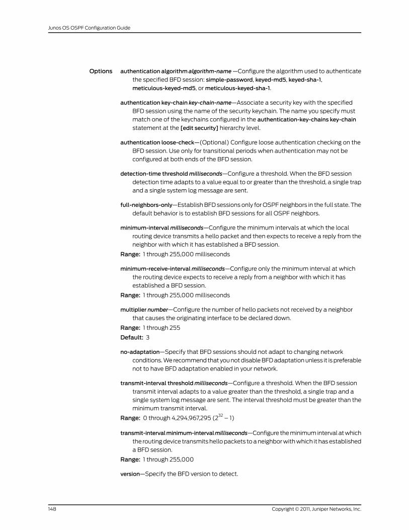
Options authentication algorithm algorithm-name—Configure the algorithm used to authenticate
the specified BFD session: simple-password, keyed-md5, keyed-sha-1,
meticulous-keyed-md5, or meticulous-keyed-sha-1.
authentication key-chain key-chain-name—Associate a security key with the specified
BFD session using the name of the security keychain. The name you specify must
match one of the keychains configured in the authentication-key-chains key-chain
statement at the [edit security] hierarchy level.
authentication loose-check—(Optional) Configure loose authentication checking on the
BFD session. Use only for transitional periods when authentication may not be
configured at both ends of the BFD session.
detection-time thresholdmilliseconds—Configure a threshold. When the BFD session
detection time adapts to a value equal to or greater than the threshold, a single trap
and a single system log message are sent.
full-neighbors-only—Establish BFD sessions only for OSPF neighbors in the full state. The
default behavior is to establish BFD sessions for all OSPF neighbors.
minimum-intervalmilliseconds—Configure the minimum intervals at which the local
routing device transmits a hello packet and then expects to receive a reply from the
neighbor with which it has established a BFD session.
Range: 1 through 255,000 milliseconds
minimum-receive-intervalmilliseconds—Configure only the minimum interval at which
the routing device expects to receive a reply from a neighbor with which it has
established a BFD session.
Range: 1 through 255,000 milliseconds
multiplier number—Configure the number of hello packets not received by a neighbor
that causes the originating interface to be declared down.
Range: 1 through 255
Default: 3
no-adaptation—Specify that BFD sessions should not adapt to changing network
conditions. We recommend that you not disable BFD adaptation unless it is preferable
not to have BFD adaptation enabled in your network.
transmit-interval thresholdmilliseconds—Configure a threshold. When the BFD session
transmit interval adapts to a value greater than the threshold, a single trap and a
single system log message are sent. The interval threshold must be greater than the
minimum transmit interval.
Range: 0 through 4,294,967,295 (232
– 1)
transmit-intervalminimum-intervalmilliseconds—Configure the minimum interval at which
the routing device transmits hello packets to a neighbor with which it has established
a BFD session.
Range: 1 through 255,000
version—Specify the BFD version to detect.
Copyright © 2011, Juniper Networks, Inc.148
Junos OS OSPF Configuration Guide
Range: 1 (BFD version 1) or automatic (autodetect version)
Default: automatic
The remaining statements are explained separately.
Required PrivilegeLevel
routing—To view this statement in the configuration.
routing-control—To add this statement to the configuration.
RelatedDocumentation
• Example: Configuring BFD for OSPF on page 72
• Configuring BFD Authentication for OSPF on page 76
149Copyright © 2011, Juniper Networks, Inc.
Summary of OSPF Configuration Statements
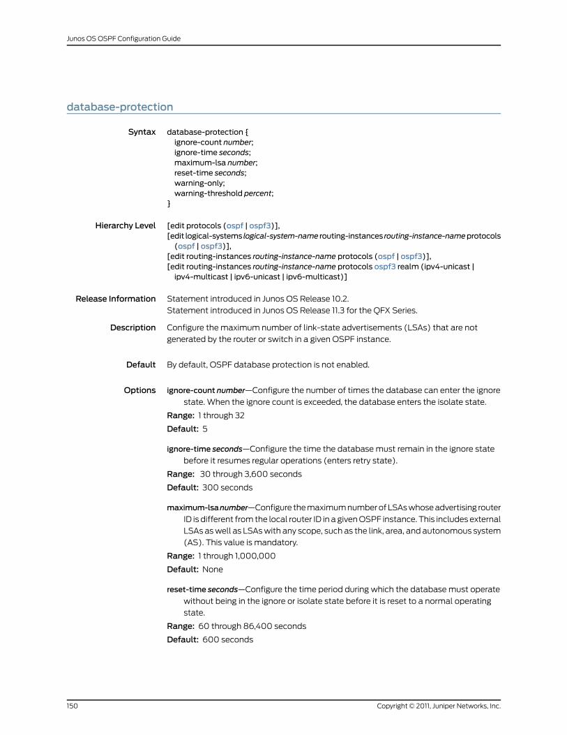
database-protection
Syntax database-protection {ignore-count number;ignore-time seconds;maximum-lsa number;reset-time seconds;warning-only;warning-threshold percent;
}
Hierarchy Level [edit protocols (ospf | ospf3)],[edit logical-systems logical-system-name routing-instances routing-instance-nameprotocols(ospf | ospf3)],
[edit routing-instances routing-instance-name protocols (ospf | ospf3)],[edit routing-instances routing-instance-name protocols ospf3 realm (ipv4-unicast |ipv4-multicast | ipv6-unicast | ipv6-multicast)]
Release Information Statement introduced in Junos OS Release 10.2.
Statement introduced in Junos OS Release 11.3 for the QFX Series.
Description Configure the maximum number of link-state advertisements (LSAs) that are not
generated by the router or switch in a given OSPF instance.
Default By default, OSPF database protection is not enabled.
Options ignore-count number—Configure the number of times the database can enter the ignore
state. When the ignore count is exceeded, the database enters the isolate state.
Range: 1 through 32
Default: 5
ignore-time seconds—Configure the time the database must remain in the ignore state
before it resumes regular operations (enters retry state).
Range: 30 through 3,600 seconds
Default: 300 seconds
maximum-lsanumber—Configure the maximum number of LSAs whose advertising router
ID is different from the local router ID in a given OSPF instance. This includes external
LSAs as well as LSAs with any scope, such as the link, area, and autonomous system
(AS). This value is mandatory.
Range: 1 through 1,000,000
Default: None
reset-time seconds—Configure the time period during which the database must operate
without being in the ignore or isolate state before it is reset to a normal operating
state.
Range: 60 through 86,400 seconds
Default: 600 seconds
Copyright © 2011, Juniper Networks, Inc.150
Junos OS OSPF Configuration Guide
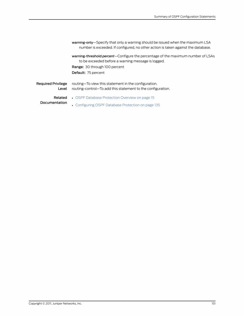
warning-only—Specify that only a warning should be issued when the maximum LSA
number is exceeded. If configured, no other action is taken against the database.
warning-threshold percent—Configure the percentage of the maximum number of LSAs
to be exceeded before a warning message is logged.
Range: 30 through 100 percent
Default: 75 percent
Required PrivilegeLevel
routing—To view this statement in the configuration.
routing-control—To add this statement to the configuration.
RelatedDocumentation
• OSPF Database Protection Overview on page 15
• Configuring OSPF Database Protection on page 135
151Copyright © 2011, Juniper Networks, Inc.
Summary of OSPF Configuration Statements
dead-interval
Syntax dead-interval seconds;
Hierarchy Level [edit logical-systems logical-system-name protocols ospf area area-id peer-interfaceinterface-name],
[edit logical-systems logical-system-name protocols (ospf | ospf3) area area-id interfaceinterface-name],
[edit logical-systems logical-system-nameprotocols (ospf | ospf3)areaarea-idvirtual-link],[edit logical-systems logical-system-name protocols ospf3 realm (ipv4-unicast |ipv4-multicast | ipv6-multicast) area area-id interface interface-name],
[edit logical-systems logical-system-name routing-instances routing-instance-nameprotocols(ospf | ospf3) area area-id interface interface-name],
[edit logical-systems logical-system-name routing-instances routing-instance-nameprotocols(ospf | ospf3) area area-id virtual-link],
[edit logical-systems logical-system-name routing-instances routing-instance-nameprotocolsospf3 realm (ipv4-unicast | ipv4-multicast | ipv6-multicast) area area-id interfaceinterface-name],
[edit protocols ospf area area-id peer-interface interface-name],[edit protocols (ospf | ospf3) area area-id interface interface-name],[edit protocols (ospf | ospf3) area area-id virtual-link],[edit protocols ospf3 realm (ipv4-unicast | ipv4-multicast | ipv6-multicast) area area-idinterface interface-name],
[edit routing-instances routing-instance-nameprotocols (ospf | ospf3)areaarea-id interfaceinterface-name],
[edit routing-instances routing-instance-name protocols (ospf | ospf3) area area-idvirtual-link],
[edit routing-instances routing-instance-name protocols ospf3 realm (ipv4-unicast |ipv4-multicast | ipv6-multicast) area area-id interface interface-name]
Release Information Statement introduced before Junos OS Release 7.4.
Statement introduced in Junos OS Release 9.0 for EX Series switches.
Support for the realm statement introduced in Junos OS Release 9.2.
Support for the realm statement introduced in Junos OS Release 9.2 for EX Series
switches.
Description Specify how long OSPF waits before declaring that a neighboring routing device is
unavailable. This is an interval during which the routing device receives no hello packets
from the neighbor.
Options seconds—Interval to wait.
Range: 1 through 65,535 seconds
Default: Four times the hello interval—40 seconds (broadcast and point-to-point
networks); 120 seconds (nonbroadcast multiple access (NBMA) networks)
Required PrivilegeLevel
routing—To view this statement in the configuration.
routing-control—To add this statement to the configuration.
RelatedDocumentation
• Example: Configuring OSPF Timers on page 66
• hello-interval on page 164
Copyright © 2011, Juniper Networks, Inc.152
Junos OS OSPF Configuration Guide
default-lsa
Syntax default-lsa {default-metricmetric;metric-type type;type-7;
}
Hierarchy Level [edit logical-systems logical-system-name protocols (ospf | ospf3) area area-id nssa],[edit logical-systems logical-system-name protocols ospf3 realm (ipv4-unicast |ipv4-multicast | ipv6-multicast) area area-id nssa],
[edit logical-systems logical-system-name routing-instances routing-instance-nameprotocols(ospf | ospf3) area area-id nssa],
[edit logical-systems logical-system-name routing-instances routing-instance-nameprotocolsospf3 realm (ipv4-unicast | ipv4-multicast | ipv6-multicast) area area-id nssa],
[edit protocols (ospf | ospf3) area area-id nssa],[edit protocols ospf3 realm (ipv4-unicast | ipv4-multicast | ipv6-multicast) area area-idnssa],
[edit routing-instances routing-instance-name protocols (ospf | ospf3) area area-id nssa],[edit routing-instances routing-instance-name protocols ospf3 realm (ipv4-unicast |ipv4-multicast | ipv6-multicast) area area-id nssa]
Release Information Statement introduced before Junos OS Release 7.4.
Statement introduced in Junos OS Release 9.0 for EX Series switches.
Support for the realm statement introduced in Junos OS Release 9.2.
Support for the realm statement introduced in Junos OS Release 9.2 for EX Series
switches.
Description On area border routers only, for a not-so-stubby area (NSSA), inject a default link-state
advertisement (LSA) with a specified metric value into the area. The default route
matches any destination that is not explicitly reachable from within the area.
The remaining statements are explained separately.
Required PrivilegeLevel
routing—To view this statement in the configuration.
routing-control—To add this statement to the configuration.
RelatedDocumentation
• OSPF Areas and Router Functionality Overview on page 8
• nssa on page 190
• stub on page 211
• Configuring OSPF Areas on page 29
153Copyright © 2011, Juniper Networks, Inc.
Summary of OSPF Configuration Statements
default-metric
Syntax default-metricmetric;
Hierarchy Level [edit logical-systems logical-system-name protocols (ospf | ospf3) area area-id nssadefault-lsa],
[edit logical-systems logical-system-name protocols (ospf | ospf3) area area-id stub],[edit logical-systems logical-system-name protocols ospf3 realm (ipv4-unicast |ipv4-multicast | ipv6-multicast) area area-id nssa default-lsa],
[edit logical-systems logical-system-name protocols ospf3 realm (ipv4-unicast |ipv4-multicast | ipv6-multicast) area area-id stub],
[edit logical-systems logical-system-name routing-instances routing-instance-nameprotocols(ospf | ospf3) area area-id nssa default-lsa],
[edit logical-systems logical-system-name routing-instances routing-instance-nameprotocols(ospf | ospf3) area area-id stub],
[edit logical-systems logical-system-name routing-instances routing-instance-nameprotocolsospf3 realm (ipv4-unicast | ipv4-multicast | ipv6-multicast)areaarea-idnssadefault-lsa],
[edit logical-systems logical-system-name routing-instances routing-instance-nameprotocolsospf3 realm (ipv4-unicast | ipv4-multicast | ipv6-multicast) area area-id stub],
[edit protocols (ospf | ospf3) area area-id nssa default-lsa],[edit protocols (ospf | ospf3) area area-id stub],[editprotocolsospf3 realm (ipv4-unicast | ipv4-multicast | ipv6-multicast)areaarea-idnssadefault-lsa],
[edit protocols ospf3 realm (ipv4-unicast | ipv4-multicast | ipv6-multicast) area area-idstub],
[edit routing-instances routing-instance-name protocols (ospf | ospf3) area area-id nssadefault-lsa],
[edit routing-instances routing-instance-name protocols (ospf | ospf3) area area-id stub],[edit routing-instances routing-instance-name protocols ospf3 realm (ipv4-unicast |ipv4-multicast | ipv6-multicast) area area-id nssa default-lsa],
[edit routing-instances routing-instance-name protocols ospf3 realm (ipv4-unicast |ipv4-multicast | ipv6-multicast) area area-id stub]
Release Information Statement introduced before Junos OS Release 7.4.
Statement introduced in Junos OS Release 9.0 for EX Series switches.
Support for the realm statement introduced in Junos OS Release 9.2.
Support for the realm statement introduced in Junos OS Release 9.2 for EX Series
switches.
Description On area border routers only, for a stub area, inject a default route with a specified metric
value into the area. The default route matches any destination that is not explicitly
reachable from within the area.
Options metric—Metric value.
Range: 1 through 16,777,215
Required PrivilegeLevel
routing—To view this statement in the configuration.
routing-control—To add this statement to the configuration.
RelatedDocumentation
OSPF Areas and Router Functionality Overview on page 8•
• nssa on page 190
Copyright © 2011, Juniper Networks, Inc.154
Junos OS OSPF Configuration Guide
• stub on page 211
demand-circuit
Syntax demand-circuit;
Hierarchy Level [edit logical-systems logical-system-name protocols (ospf | ospf3) area area-id interfaceinterface-name],
[edit logical-systems logical-system-name protocols ospf3 realm (ipv4-unicast |ipv4-multicast | ipv6-multicast) area area-id interface interface-name],
[edit logical-systems logical-system-name routing-instances routing-instance-nameprotocolsospf area area-id sham-link-remote],
[edit logical-systems logical-system-name routing-instances routing-instance-nameprotocols(ospf | ospf3) area area-id interface interface-name],
[edit logical-systems logical-system-name routing-instances routing-instance-nameprotocolsospf3 realm (ipv4-unicast | ipv4-multicast | ipv6-multicast) area area-id interfaceinterface-name],
[edit protocols (ospf | ospf3) area area-id interface interface-name],[edit protocols ospf3 realm (ipv4-unicast | ipv4-multicast | ipv6-multicast) area area-idinterface interface-name],
[edit routing-instances routing-instance-nameprotocols (ospf | ospf3)areaarea-id interfaceinterface-name],
[edit routing-instances routing-instance-nameprotocolsospfareaarea-idsham-link-remote],[edit routing-instances routing-instance-name protocols ospf3 realm (ipv4-unicast |ipv4-multicast | ipv6-multicast) area area-id interface interface-name]
Release Information Statement introduced before Junos OS Release 7.4.
Support for the realm statement introduced in Junos OS Release 9.2.
Description Configure an interface as a demand circuit.
Required PrivilegeLevel
routing—To view this statement in the configuration.
routing-control—To add this statement to the configuration.
RelatedDocumentation
• Example: Configuring OSPF Demand Circuits
• Example: Configuring OSPFv2 Sham Links on page 117
155Copyright © 2011, Juniper Networks, Inc.
Summary of OSPF Configuration Statements
disable (LDP Synchronization)
Syntax disable;
Hierarchy Level [edit logical-systems logical-system-name protocols (ospf | ospf3) area area-id interfaceinterface-name],
[edit logical-systems logical-system-name routing-instances routing-instance-nameprotocols(ospf | ospf3) area area-id interface interface-name],
[edit protocols (ospf | ospf3) area area-id interface interface-name],[edit routing-instances routing-instance-nameprotocols (ospf |ospf3)areaarea-id interfaceinterface-name]
Release Information Statement introduced in Junos OS Release 7.5.
Description Disable LDP for OSPF.
Required PrivilegeLevel
routing—To view this statement in the configuration.
routing-control—To add this statement to the configuration.
RelatedDocumentation
• Example: Configuring Synchronization Between LDP and IGPs on page 79
Copyright © 2011, Juniper Networks, Inc.156
Junos OS OSPF Configuration Guide
disable (OSPF)
Syntax disable;
Hierarchy Level [edit logical-systems logical-system-name protocols (ospf | ospf3)],[edit logical-systems logical-system-name protocols (ospf | ospf3) area area-id interfaceinterface-name],
[edit logical-systems logical-system-name protocols (ospf | ospf3) virtual-link],[edit logical-systems logical-system-name protocols ospf3 realm (ipv4-unicast |ipv4-multicast | ipv6-multicast)],
[edit logical-systems logical-system-name protocols ospf3 realm (ipv4-unicast |ipv4-multicast | ipv6-multicast) area area-id interface interface-name],
[edit logical-systems logical-system-name routing-instances routing-instance-nameprotocols(ospf | ospf3)],
[edit logical-systems logical-system-name routing-instances routing-instance-nameprotocols(ospf | ospf3) area area-id interface interface-name],
[edit logical-systems logical-system-name routing-instances routing-instance-nameprotocols(ospf | ospf3) virtual-link],
[edit logical-systems logical-system-name routing-instances routing-instances protocolsospf3 realm (ipv4-unicast | ipv4-multicast | ipv6-multicast)],
[edit logical-systems logical-system-name routing-instances routing-instance-nameprotocolsospf3 realm (ipv4-unicast | ipv4-multicast | ipv6-multicast) area area-id interfaceinterface-name],
[edit protocols (ospf | ospf3)],[edit protocols (ospf | ospf3) area area-id interface interface-name],[edit protocols (ospf | ospf3) virtual-link],[edit protocols ospf3 realm (ipv4-unicast | ipv4-multicast | ipv6-multicast)],[edit protocols ospf3 realm (ipv4-unicast | ipv4-multicast | ipv6-multicast) area area-idinterface interface-name],
[edit routing-instances routing-instance-name protocols (ospf | ospf3)],[edit routing-instances routing-instance-nameprotocols (ospf |ospf3)areaarea-id interfaceinterface-name],
[edit routing-instances routing-instance-name protocols (ospf | ospf3) virtual-link],[edit routing-instances routing-instance-name protocols ospf3 realm (ipv4-unicast |ipv4-multicast | ipv6-multicast)],
[edit routing-instances routing-instance-name protocols ospf3 realm (ipv4-unicast |ipv4-multicast | ipv6-multicast) area area-id interface interface-name]
Release Information Statement introduced before Junos OS Release 7.4.
Statement introduced in Junos OS Release 9.0 for EX Series switches.
Support for the realm statement introduced in Junos OS Release 9.2.
Support for the realm statement introduced in Junos OS Release 9.2 for EX Series
switches.
Statement introduced in Junos OS Release 11.3 for the QFX Series.
Description Disable OSPF, an OSPF interface, or an OSPF virtual link.
Default The configured object is enabled (operational) unless explicitly disabled.
Required PrivilegeLevel
routing—To view this statement in the configuration.
routing-control—To add this statement to the configuration.
157Copyright © 2011, Juniper Networks, Inc.
Summary of OSPF Configuration Statements
RelatedDocumentation
• OSPF Configuration Overview
domain-id
Syntax domain-id domain-id;
Hierarchy Level [edit logical-systems logical-system-name routing-instances routing-instance-nameprotocols(ospf | ospf3)],
[edit routing-instances routing-instance-name protocols (ospf | ospf3)]
Release Information Statement introduced before Junos OS Release 7.4.
Statement introduced in Junos OS Release 9.0 for EX Series switches.
Description Specify a domain ID for a route. The domain ID identifies the OSPF domain from which
the route originated.
Options domain-id—You can specify either an IP address or an IP address and a local identifier
using the following format: ip-address:local-identifier. If you do not specify a local
identifier with the IP address, the identifier is assumed to have a value of 0.
Default: If the router ID is not configured in the routing instance, the router ID is derived
from an interface address belonging to the routing instance.
Required PrivilegeLevel
routing—To view this statement in the configuration.
routing-control—To add this statement to the configuration.
RelatedDocumentation
• Configuring OSPF Domain IDs for VPNs
domain-vpn-tag
Syntax domain-vpn-tag number;
Hierarchy Level [edit logical-systems logical-system-name routing-instances routing-instance-nameprotocols(ospf | ospf3)],
[edit routing-instances routing-instance-name protocols (ospf | ospf3)]
Release Information Statement introduced before Junos OS Release 7.4.
Statement introduced in Junos OS Release 9.0 for EX Series switches.
Description Set a virtual private network (VPN) tag for OSPFv2 external routes generated by the
provider edge (PE) router.
Options number—VPN tag.
Required PrivilegeLevel
routing—To view this statement in the configuration.
routing-control—To add this statement to the configuration.
RelatedDocumentation
• Configuring OSPF Domain IDs for VPNs
Copyright © 2011, Juniper Networks, Inc.158
Junos OS OSPF Configuration Guide
export
Syntax export [ policy-names ];
Hierarchy Level [edit logical-systems logical-system-name protocols (ospf | ospf3)],[edit logical-systems logical-system-name protocols ospf3 realm (ipv4-unicast |ipv4-multicast | ipv6-multicast)],
[edit logical-systems logical-system-name routing-instances routing-instance-nameprotocols(ospf | ospf3)],
[edit logical-systems logical-system-name routing-instances routing-instance-nameprotocolsospf3 realm (ipv4-unicast | ipv4-multicast | ipv6-multicast)],
[edit protocols (ospf | ospf3)],[edit protocols ospf3 realm (ipv4-unicast | ipv4-multicast | ipv6-multicast)],[edit routing-instances routing-instance-name protocols (ospf | ospf3)],[edit routing-instances routing-instance-name protocols ospf3 realm (ipv4-unicast |ipv4-multicast | ipv6-multicast)]
Release Information Statement introduced before Junos OS Release 7.4.
Statement introduced in Junos OS Release 9.0 for EX Series switches.
Support for the realm statement introduced in Junos OS Release 9.2.
Support for the realm statement introduced in Junos OS Release 9.2 for EX Series
switches.
Statement introduced in Junos OS Release 11.3 for the QFX Series.
Description Apply one or more policies to routes being exported from the routing table into OSPF.
Options policy-names—Name of one or more policies.
Required PrivilegeLevel
routing—To view this statement in the configuration.
routing-control—To add this statement to the configuration.
RelatedDocumentation
• Understanding OSPF Routing Policy
• Import and Export Policies for Network Summaries Overview
• import on page 166
• Junos OS Routing Policy Configuration Guide
159Copyright © 2011, Juniper Networks, Inc.
Summary of OSPF Configuration Statements
external-preference
Syntax external-preference preference;
Hierarchy Level [edit logical-systems logical-system-name protocols (ospf | ospf3)],[edit logical-systems logical-system-nameprotocolsospf3 realm(ip4-unicast | ipv4-multicast| ipv6-multicast)],
[edit logical-systems logical-system-name routing-instances routing-instance-nameprotocols(ospf | ospf3)],
[edit logical-systems logical-system-name routing-instances routing-instance-nameprotocolsospf3 realm (ipv4-unicast | ipv4-multicast | ipv6-multicast)],
[edit protocols (ospf | ospf3)],[edit protocols ospf3 realm (ipv4-unicast | ipv4-multicast | ipv6-multicast)],[edit routing-instances routing-instance-name protocols (ospf | ospf3)],[edit routing-instances routing-instance-name protocols ospf3 realm (ipv4-unicast }ipv4-multicast | ipv6-multicast)]
Release Information Statement introduced before Junos OS Release 7.4.
Statement introduced in Junos OS Release 9.0 for EX Series switches.
Support for the realm statement introduced in Junos OS Release 9.2.
Support for the realm statement introduced in Junos OS Release 9.2 for EX Series
switches.
Statement introduced in Junos OS Release 11.3 for the QFX Series.
Description Set the route preference for OSPF external routes.
Options preference—Preference value.
Range: 0 through 4,294,967,295 (232
– 1)
Default: 150
Required PrivilegeLevel
routing—To view this statement in the configuration.
routing-control—To add this statement to the configuration.
RelatedDocumentation
• Example: Controlling OSPF Route Preferences on page 63
• preference on page 198
Copyright © 2011, Juniper Networks, Inc.160
Junos OS OSPF Configuration Guide
flood-reduction
Syntax flood-reduction;
Hierarchy Level [edit protocols (ospf | ospf3) area area-id interface interface-name],[edit logical-systems logical-system-name protocols (ospf | ospf3) area area-id interfaceinterface-name],
[edit routing-instances routing-instance-nameprotocols (ospf | ospf3)areaarea-id interfaceinterface-name],
[edit logical-systems logical-system-name routing-instances routing-instance-nameprotocols(ospf | ospf3) area area-id interfaces interface-name],
[edit protocols ospf3 realm (ipv4-multicast | ipv4-unicast | ipv6-multicast) area area-idinterfaces interface-name],
[edit logical-systems logical-system-name protocols ospf3 realm (ipv4-multicast |ipv4-unicast | ipv6-multicast) area area-id interfaces interface-name],
[edit routing-instances routing-instance-name protocols ospf3 realm (ipv4-multicast |ipv4-unicast | ipv6-multicast) area area-id interfaces interface-name],
[edit logical-systems logical-system-name routing-instances routing-instance-nameprotocolsospf3 realm (ipv4-multicast | ipv4-unicast | ipv6-multicast) area area-id interfacesinterface-name],
[edit protocols (ospf | ospf3) area area-id virtual-link neighbor-id router-id transit-areaarea-id],
[edit logical-systems logical-system-name protocols (ospf | ospf3) area area-id virtual-linkneighbor-id router-id transit–area transit-area area-id],
[edit routing-instances routing-instance-nameprotocols (ospf |ospf3)areaarea-idvirtual-linkneighbor-id router-id transit-area area-id],
[edit logical-systems logical-system-name routing-instances routing-instance-nameprotocols(ospf | ospf3) area area-id virtual-link neighbor-id router-id transit-area area-id],
[edit routing-instances routing-instance-nameprotocolsospfareaarea-idsham-link-remoteaddress ],
[edit logical-systems logical-system-name routing-instances routing-instance-nameprotocolsospf area area-id sham-link-remote address],
[edit protocols ospf area area-id peer-interface interface-name],[edit logical-systems logical-system-name protocols ospf area area-id peer-interfaceinterface-name]
Release Information Statement introduced in Junos OS Release 9.6.
Description Specify to send self-generated link-state advertisements (LSAs) with the DoNotAge bit
set. As a result, self-originated LSAs are not reflooded every 30 minutes, as required by
OSPF by default. An LSA is refreshed only when the content of the LSA changes, which
reduces OSPF traffic overhead in stable topologies.
Required PrivilegeLevel
routing—To view this statement in the configuration.
routing-control—To add this statement to the configuration.
RelatedDocumentation
• Configuring OSPF Refresh and Flooding Reduction in Stable Topologies on page 71
161Copyright © 2011, Juniper Networks, Inc.
Summary of OSPF Configuration Statements
graceful-restart
Syntax graceful-restart {disable;helper-disable <standard | restart-signaling | both>;no-strict-lsa-checking;notify-duration seconds;restart-duration seconds;
}
Hierarchy Level [edit logical-systems logical-system-name protocols (ospf | ospf3)],[edit logical-systems logical-system-name routing-instances routing-instance-nameprotocols(ospf | ospf3)],
[edit protocols (ospf | ospf3)][edit routing-instances routing-instance-name protocols ospf]
Release Information Statement introduced before Junos OS Release 7.4.
Support for the no-strict-lsa-checking statement introduced in Junos OS Release 8.5.
Statement introduced in Junos OS Release 9.0 for EX Series switches.
Support for the helper mode standard, restart-signaling, and both options introduced in
Junos OS Release 11.4.
Description Configure graceful restart for OSPF.
Options disable—Disable graceful restart for OSPF.
helper-disable <standard | restart-signaling| both>—Disable helper mode for graceful
restart. When helper mode is disabled, a device cannot help a neighboring device
that is attempting to restart. Beginning with Junos OS Release 11.4, you can configure
restart signaling-based helper mode for OSPFv2 graceful restart configurations. The
standard, restart-signaling, and both options are only supported for OSPFv2. Specify
standard to disable helper mode for standard graceful restart (based on RFC 3623).
Specify restart-signaling to disable helper mode for restart signaling-based graceful
restart (based on RFC 4811, RFC 4812, and RFC 4813). Specify both to disable helper
mode for both standard and restart signaling-based graceful restart. The last
committed statement takes precedence over the previously-configured statement.
Default: Helper mode is enabled by default. For OSPFv2, both standard and
restart-signaling based helper modes are enabled by default.
no-strict-lsa-checking—Disable strict OSPF link-state advertisement (LSA) checking to
prevent the termination of graceful restart by a helping router. LSA checking is enabled
by default.
NOTE: Thehelper-disablestatementandtheno-strict-lsa-checkingstatement
cannot be configured at the same time. If you attempt to configure bothstatements at the same time, the routing device displays awarningmessagewhen you enter the show protocols (ospf | ospf3) command.
Copyright © 2011, Juniper Networks, Inc.162
Junos OS OSPF Configuration Guide
notify-duration seconds—Estimated time to send out purged grace LSAs over all the
interfaces.
Range: 1 through 3600 seconds
Default: 30 seconds
restart-duration seconds—Estimated time to reacquire a full OSPF neighbor from each
area.
Range: 1 through 3600 seconds
Default: 180 seconds
Required PrivilegeLevel
routing—To view this statement in the configuration.
routing-control—To add this statement to the configuration.
RelatedDocumentation
• Example: Configuring Graceful Restart for OSPF on page 82
• Example: Configuring the Helper Capability Mode for OSPFv2 Graceful Restart
• Example: Configuring the Helper Capability Mode for OSPFv3 Graceful Restart
• Example: Disabling Strict LSA Checking for OSPF Graceful Restart
• Junos OS High Availability Configuration Guide
163Copyright © 2011, Juniper Networks, Inc.
Summary of OSPF Configuration Statements
hello-interval
Syntax hello-interval seconds;
Hierarchy Level [edit logical-systems logical-system-name protocols ospf area area-id peer-interfaceinterface-name],
[edit logical-systems logical-system-name protocols (ospf | ospf3) area area-id interfaceinterface-name],
[edit logical-systems logical-system-nameprotocols (ospf | ospf3)areaarea-idvirtual-link],[edit logical-systems logical-system-name protocols ospf3 realm (ipv4-unicast |ipv4-multicast | ipv6-multicast) area area-id interface interface-name],
[edit logical-systems logical-system-name routing-instances routing-instance-nameprotocols(ospf | ospf3) area area-id interface interface-name],
[edit logical-systems logical-system-name routing-instances routing-instance-nameprotocols(ospf | ospf3) area area-id virtual-link],
[edit logical-systems logical-system-name routing-instances routing-instance-nameprotocolsospf3 realm (ipv4-unicast | ipv4-multicast | ipv6-multicast) area area-id interfaceinterface-name],
[edit protocols ospf area area-id peer-interface interface-name],[edit protocols (ospf | ospf3) area area-id interface interface-name],[edit protocols (ospf | ospf3) area area-id virtual-link],[edit protocols ospf3 realm (ipv4-unicast | ipv4-multicast | ipv6-multicast) area area-idinterface interface-name],
[edit routing-instances routing-instance-nameprotocols (ospf | ospf3)areaarea-id interfaceinterface-name],
[edit routing-instances routing-instance-name protocols (ospf | ospf3) area area-idvirtual-link],
[edit routing-instances routing-instance-name protocols ospf3 realm (ipv4-unicast |ipv4-multicast | ipv6-multicast) area area-id interface interface-name]
Release Information Statement introduced before Junos OS Release 7.4.
Statement introduced in Junos OS Release 9.0 for EX Series switches.
Support for the realm statement introduced in Junos OS Release 9.2.
Support for the realm statement introduced in Junos OS Release 9.2 for EX Series
switches.
Description Specify how often the routing device sends hello packets out the interface. The hello
interval must be the same for all routing devices on a shared logical IP network.
Options seconds—Time between hello packets, in seconds.
Range: 1 through 255 seconds
Default: 10 seconds (broadcast and point-to-point networks); 30 seconds (nonbroadcast
multiple access [NBMA] networks)
Required PrivilegeLevel
routing—To view this statement in the configuration.
routing-control—To add this statement to the configuration.
RelatedDocumentation
• Example: Configuring OSPF Timers on page 66
• dead-interval on page 152
Copyright © 2011, Juniper Networks, Inc.164
Junos OS OSPF Configuration Guide
hold-time
Syntax hold-time seconds;
Hierarchy Level [edit logical-systems logical-system-name protocols ospf area area-id interfaceinterface-name],
[edit logical-systems logical-system-name routing-instances routing-instance-nameprotocolsospf area area-id interface interface-name],
[edit protocols ospf area area-id interface interface-name],[edit routing-instances routing-instance-name protocols ospf area area-id interfaceinterface-name]
Release Information Statement introduced in Junos OS Release 7.5.
Description Configure the time period to advertise the maximum cost metric for a link that is not fully
operational.
Options seconds—Hold-time value.
Range: 1 through 65,535 seconds
Default: Infinity
Required PrivilegeLevel
routing—To view this statement in the configuration.
routing-control—To add this statement to the configuration.
RelatedDocumentation
• Example: Configuring Synchronization Between LDP and IGPs on page 79
ignore-lsp-metrics
Syntax ignore-lsp-metrics;
Hierarchy Level [edit logical-systems logical-system-name protocols ospf traffic-engineering shortcuts],[edit logical-systems logical-system-name routing-instances routing-instance-nameprotocolsospf traffic-engineering shortcuts],
[edit protocols ospf traffic-engineering shortcuts],[edit routing-instances routing-instance-nameprotocols ospf traffic-engineering shortcuts]
Release Information Statement introduced in Junos OS Release 7.5.
Statement introduced in Junos OS Release 9.0 for EX Series switches.
Support for (OSPFv3) introduced in Junos OS Release 9.4.
Support for (OSPFv3) introduced in Junos OS Release 9.4 for EX Series switches.
Description Ignore RSVP LSP metrics in OSPF traffic engineering shortcut calculations.
Required PrivilegeLevel
routing—To view this statement in the configuration.
routing-control—To add this statement to the configuration.
RelatedDocumentation
• Example: Enabling OSPF Traffic Engineering Support on page 107
165Copyright © 2011, Juniper Networks, Inc.
Summary of OSPF Configuration Statements
import
Syntax import [ policy-names ];
Hierarchy Level [edit logical-systems logical-system-name protocols (ospf | ospf3)],[edit logical-systems logical-system-name protocols ospf3 realm (ipv4-unicast |ipv4-multicast | ipv6-multicast)],
[edit logical-systems logical-system-name routing-instances routing-instance-nameprotocols(ospf | ospf3)],
[edit logical-systems logical-system-name routing-instances routing-instance-nameprotocolsospf3 realm (ipv4-unicast | ipv4-multicast | ipv6-multicast)],
[edit protocols (ospf | ospf3)],[edit protocols ospf3 realm (ipv4-unicast | ipv4-multicast | ipv6-multicast)],[edit routing-instances routing-instance-name protocols (ospf | ospf3)],[edit routing-instances routing-instance-name protocols ospf3 realm (ipv4-unicast |ipv4-multicast | ipv6-multicast)]
Release Information Statement introduced before Junos OS Release 7.4.
Statement introduced in Junos OS Release 9.0 for EX Series switches.
Support for the realm statement introduced in Junos OS Release 9.2.
Support for the realm statement introduced in Junos OS Release 9.2 for EX Series
switches.
Statement introduced in Junos OS Release 11.3 for the QFX Series.
Description Filter OSPF routes from being added to the routing table.
Options policy-names—Name of one or more policies.
Required PrivilegeLevel
routing—To view this statement in the configuration.
routing-control—To add this statement to the configuration.
RelatedDocumentation
• Understanding OSPF Routing Policy
• Import and Export Policies for Network Summaries Overview
• export on page 159
• Junos OS Routing Policy Configuration Guide
Copyright © 2011, Juniper Networks, Inc.166
Junos OS OSPF Configuration Guide
inter-area-prefix-export
Syntax inter-area-prefix-export [ policy-names ];
Hierarchy Level [edit logical-systems logical-system-name protocols ospf3 area area-id],[edit logical-systems logical-system-name routing-instances routing-instance-nameprotocolsospf3 area area-id],
[edit logical-systems logical-system-name routing-instances routing-instance-nameprotocolsospf3 realm (ip4-unicast | ipv4-multicast | ipv6-multicast) area area-id],
[edit protocols ospf3 area area-id],[edit protocols ospf3 realm (ipv4-unicast | ipv4-multicast | ipv6-multicast) area area-id],[edit routing-instances routing-instance-name protocols ospf3 area area-id],[edit routing-instances routing-instance-name protocols ospf3 realm (ipv4-unicast |ipv4-muticast | ipv6-multicast) area area-id]
Release Information Statement introduced in Junos OS Release 9.1.
Statement introduced in Junos OS Release 9.1 for EX Series switches.
Support for the realm statement introduced in Junos OS Release 9.2.
Support for the realm statement introduced in Junos OS Release 9.2 for EX Series
switches.
Description Apply an export policy for OSPFv3 to specify which interarea prefix link-state
advertisements (LSAs) are flooded into an area.
Options policy-name—Name of a policy configured at the [edit policy-options policy-statement
policy-name term term-name] hierarchy level.
Required PrivilegeLevel
routing—To view this statement in the configuration.
routing-control—To add this statement to the configuration.
RelatedDocumentation
• Import and Export Policies for Network Summaries Overview
• inter-area-prefix-import on page 168
• Junos OS Routing Policy Configuration Guide
167Copyright © 2011, Juniper Networks, Inc.
Summary of OSPF Configuration Statements
inter-area-prefix-import
Syntax inter-area-prefix-import [ policy-names ];
Hierarchy Level [edit logical-systems logical-system-name protocols ospf3 area area-id],[edit logical-systems logical-system-name protocols ospf3 realm (ipv4-unicast |ipv4-multicast | ipv6-multicast) area area-id],
[edit logical-systems logical-system-name routing-instances routing-instance-nameprotocolsospf3 area area-id],
[edit logical-systems logical-system-name routing-instances routing-instance-nameprotocolsospf3 realm (ipv4-unicast | ipv4-multicast | ipv6-multicast) area area-id],
[edit protocols ospf3 area area-id],[edit protocols ospf3 realm (ip4-unicast | ipv4-multicast | ipv6-multicast)], area area-id],[edit routing-instances routing-instance-name protocols ospf3 area area-id],[edit routing-instances routing-instance-name protocols ospf3 realm (ipv4-unicast |ipv4-multicast | ipv6-multicast) area area-id]
Release Information Statement introduced in Junos OS Release 9.1.
Statement introduced in Junos OS Release 9.1 for EX Series switches.
Support for the realm statement introduced in Junos OS Release 9.2.
Support for the realm statement introduced in Junos OS Release 9.2 for EX Series
switches.
Description Apply an import policy for OSPFv3 to specify which routes learned from an area are used
to generate interarea prefixes into other areas.
Options policy-name—Name of a policy configured at the [edit policy-options policy-statement
policy-name term term-name] hierarchy level.
Required PrivilegeLevel
routing—To view this statement in the configuration.
routing-control—To add this statement to the configuration.
RelatedDocumentation
• Import and Export Policies for Network Summaries Overview
• inter-area-prefix-export on page 167
• Junos OS Routing Policy Configuration Guide
Copyright © 2011, Juniper Networks, Inc.168
Junos OS OSPF Configuration Guide
interface
Syntax interface interface-name {disable;authentication key <key-id identifier>;bfd-liveness-detection {authentication {algorithm algorithm-name;key-chain key-chain-name;loose-check;
}detection-time {thresholdmilliseconds;
}minimum-intervalmilliseconds;minimum-receive-intervalmilliseconds;transmit-interval {thresholdmilliseconds;minimum-intervalmilliseconds;
}multiplier number;
}dead-interval seconds;demand-circuit;hello-interval seconds;ipsec-sa name;interface-type type;ldp-synchronization {disable;hold-time seconds;
}metricmetric;neighbor address <eligible>;no-interface-state-traps;passive;poll-interval seconds;priority number;retransmit-interval seconds;te-metricmetric;topology (ipv4-multicast | name) {metricmetric;
}transit-delay seconds;transmit-interval seconds;
}
Hierarchy Level [edit logical-systems logical-system-name protocols (ospf | ospf3) area area-id],[edit logical-systems logical-system-name protocols ospf3 realm (ipv4-unicast |ipv4-multicast | ipv6-multicast) area area-id],
[edit logical-systems logical-system-name routing-instances routing-instance-nameprotocols(ospf | ospf3) area area-id],
[edit logical-systems logical-system-name routing-instances routing-instance-nameprotocolsospf3 realm (ipv4-unicast | ipv4-multicast | ipv6-multicast) area area-id],
[edit protocols (ospf | ospf3) area area-id],
169Copyright © 2011, Juniper Networks, Inc.
Summary of OSPF Configuration Statements
[edit protocols ospf3 realm (ipv4-unicast | ipv4-multicast | ipv6-multicast) area area-id],[edit routing-instances routing-instance-name protocols (ospf | ospf3) area area-id],[edit routing-instances routing-instance-name protocols ospf3 realm (ipv4-unicast |ipv4-multicast | ipv6-multicast) area area-id]
Release Information Statement introduced before Junos OS Release 7.4.
Statement introduced in Junos OS Release 9.0 for EX Series switches.
Support for the topology statement introduced in Junos OS Release 9.0.
Support for the topology statement introduced in Junos OS Release 9.0 for EX Series
switches.
Support for the realm statement introduced in Junos OS Release 9.2.
Support for the realm statement introduced in Junos OS Release 9.2 for EX Series
switches.
Support for the no-interface-state-traps statement introduced in Junos OS Release 10.3.
This statement is supported only for OSPFv2.
Description Enable OSPF routing on a routing device interface.
You must include at least one interface statement in the configuration to enable OSPF
on the routing device.
Options interface-name—Name of the interface. Specify the interface by IP address or interface
name for OSPFv2, or only the interface name for OSPFv3. Using both the interface
name and IP address of the same interface produces an invalid configuration. To
configure all interfaces, you can specify all. Specifying a particular interface and all
produces an invalid configuration.
NOTE: For nonbroadcast interfaces, specify the IP address of thenonbroadcast interface as interface-name.
The remaining statements are explained separately.
NOTE: You cannot run both OSPF and ethernet-tcc encapsulation between
two Juniper Networks routing devices.
Required PrivilegeLevel
routing—To view this statement in the configuration.
routing-control—To add this statement to the configuration.
RelatedDocumentation
• OSPF Configuration Overview
• Configuring Multitopology Routing in OSPF
• Example: Configuring Multiple Address Families for OSPFv3 on page 41
• neighbor on page 182
Copyright © 2011, Juniper Networks, Inc.170
Junos OS OSPF Configuration Guide
interface-type
Syntax interface-type (nbma | p2mp | p2p);
Hierarchy Level [edit logical-systems logical-system-name protocols (ospf | ospf3) area area-id interfaceinterface-name],
[edit logical-systems logical-system-name protocols ospf3 realm (ipv4-multicast |ipv4-unicast | ipv6-multicast) area area-id interface interface-name],
[edit logical-systems logical-system-name routing-instances routing-instance-nameprotocols(ospf | ospf3) area area-id interface interface-name],
[edit logical-systems logical-system-name routing-instances routing-instance-nameprotocolsospf3 realm (ipv4-multicast | ipv4-unicast | ipv6-multicast) area area-id interfaceinterface-name],
[edit protocols (ospf | ospf3) area area-id interface interface-name],[edit protocols ospf3 realm (ipv4-multicast | ipv4-unicast | ipv6-multicast) area area-idinterface interface-name],
[edit routing-instances routing-instance-nameprotocols (ospf | ospf3)areaarea-id interfaceinterface-name],
[edit routing-instances routing-instance-name protocols ospf3 realm (ipv4-multicast |ipv4-unicast | ipv6-multicast) area area-id interface interface-name]
Release Information Statement introduced before Junos OS Release 7.4.
Statement introduced in Junos OS Release 9.0 for EX Series switches.
Support for OSPFv3 for interface type p2p only introduced in Junos OS Release 9.4. You
cannot configure other interface types for OSPFv3.
Support for OSPFv3 for interface type p2p only introduced in Junos OS Release 9.4 for
EX Series switches.
Description Specify the type of interface.
By default, the software chooses the correct interface type based on the type of physical
interface. Therefore, you should never have to set the interface type. The exception to
this is for NBMA interfaces, which default to an interface type of point-to-multipoint. To
have these interfaces explicitly run in Nonbroadcast multiaccess (NBMA) mode, configure
the nbma interface type, using the IP address of the local ATM interface.
In Junos OS Release 9.3 and later, a point-to-point interface can be an Ethernet interface
without a subnet.
Default The software chooses the correct interface type based on the type of physical interface.
Options nbma (OSPFv2 only)—Nonbroadcast multiaccess (NBMA) interface.
p2mp (OSPFv2 only)—Point-to-multipoint interface.
p2p—Point-to-point interface.
Required PrivilegeLevel
routing—To view this statement in the configuration.
routing-control—To add this statement to the configuration.
171Copyright © 2011, Juniper Networks, Inc.
Summary of OSPF Configuration Statements

RelatedDocumentation
• About OSPF Interfaces
• Example: Configuring an OSPFv2 Interface on a Nonbroadcast Multiaccess Network
Copyright © 2011, Juniper Networks, Inc.172
Junos OS OSPF Configuration Guide
ipsec-sa
Syntax ipsec-sa name;
Hierarchy Level [edit logical-systems logical-system-name protocols (ospf | ospf3) area area-id interfaceinterface-name],
[edit logical-systems logical-system-nameprotocols (ospf | ospf3)areaarea-idvirtual-link],[edit logical-systems logical-system-name protocols ospf3 realm (ipv4-unicast |ipv4-multicast | ipv6-multicast) area area-id interface interface-name],
[edit logical-systems logical-system-name routing-instances routing-instance-nameprotocols(ospf | ospf3) area area-id interface interface-name],
[edit logical-systems logical-system-name routing-instances routing-instance-nameprotocolsospf area area-id sham-link-remote address],
[edit logical-systems logical-system-name routing-instances routing-instance-nameprotocols(ospf | ospf3) area area-id virtual-link],
[edit logical-systems logical-system-name routing-instances routing-instance-nameprotocolsospf3 realm (ipv4-unicast | ipv4-multicast | ipv6-multicast) area area-id interfaceinterface-name],
[edit protocols (ospf | ospf3) area area-id interface interface-name],[edit protocols (ospf | ospf3) area area-id virtual-link],[edit protocols ospf3 realm (ipv4-unicast | ipv4-multicast | ipv6-multicast) area area-idinterface interface-name],
[edit routing-instances routing-instance-nameprotocols (ospf |ospf3)areaarea-id interfaceinterface-name],
[edit routing-instances routing-instance-nameprotocolsospfareaarea-idsham-link-remoteaddress],
[edit routing-instances routing-instance-name protocols (ospf | ospf3) area area-idvirtual-link],
[edit routing-instances routing-instance-name protocols ospf3 realm (ipv4-unicast |ipv4-multicast | ipv6-multicast) area area-id interface interface-name]
Release Information Statement introduced before Junos OS Release 7.4.
Support for OSPFv2 authentication added in Junos OS Release 8.3.
Support for the realm statement introduced in Junos OS Release 9.2.
Description Apply IPsec authentication to an OSPF interface or virtual link or to an OSPFv2 remote
sham link.
Options name—Name of the IPsec authentication scheme.
Required PrivilegeLevel
routing—To view this statement in the configuration.
routing-control—To add this statement to the configuration.
RelatedDocumentation
• Understanding OSPFv2 Authentication
• Understanding OSPFv3 Authentication
• Example: Configuring IPsec Authentication for an OSPF Interface
• Junos OS System Basics Configuration Guide
• Junos OS Services Interfaces Configuration Guide
173Copyright © 2011, Juniper Networks, Inc.
Summary of OSPF Configuration Statements
label-switched-path
Syntax label-switched-path namemetricmetric;
Hierarchy Level [edit logical-systems logical-system-name protocols ospf area area-id],[edit logical-systems logical-system-name routing-instances routing-instance-nameprotocolsospf area area-id],
[edit protocols ospf area area-id],[edit routing-instances routing-instance-name protocols ospf area area-id]
Release Information Statement introduced before Junos OS Release 7.4.
Description Advertise label-switched paths into OSPF as point-to-point links.
The label-switched path is advertised in the appropriate OSPF levels as a point-to-point
link and contains a local address and a remote address.
Options name—Name of the label-switched path.
metric—Metric value.
Range: 1 through 65,535
Default: 1
Required PrivilegeLevel
routing—To view this statement in the configuration.
routing-control—To add this statement to the configuration.
RelatedDocumentation
• Example: Advertising Label-Switched Paths into OSPFv2 on page 93
Copyright © 2011, Juniper Networks, Inc.174
Junos OS OSPF Configuration Guide
ldp-synchronization
Syntax ldp-synchronization {disable;hold-time seconds;
}
Hierarchy Level [edit logical-systems logical-system-name protocols ospf area area-id interfaceinterface-name],
[edit logical-systems logical-system-name protocols ospf3 realm ipv4-unicast area area-idinterface interface-name],
[edit logical-systems logical-system-name routing-instances routing-instance-nameprotocolsospf area area-id interface interface-name],
[edit logical-systems logical-system-name routing-instances routing-instance-nameprotocolsospf3 realm ipv4-unicast area area-id interface interface-name],
[edit protocols ospf area area-id interface interface-name],[edit protocols ospf3 realm ipv4-unicast area area-id interface interface-name],[edit routing-instances routing-instance-name protocols ospf area area-id interfaceinterface-name],
[edit routing-instances routing-instance-name protocols ospf3 realm ipv4-unicast areaarea-id interface interface-name]
Release Information Statement introduced in Junos OS Release 7.5.
Support for the realm statement introduced in Junos OS Release 9.2. Only the ipv4-unicast
option is supported with this statement.
Description Enable synchronization by advertising the maximum cost metric until LDP is operational
on the link.
The remaining statements are explained separately.
Required PrivilegeLevel
routing—To view this statement in the configuration.
routing-control—To add this statement to the configuration.
RelatedDocumentation
• Example: Configuring Synchronization Between LDP and IGPs on page 79
175Copyright © 2011, Juniper Networks, Inc.
Summary of OSPF Configuration Statements
link-protection
Syntax link-protection;
Hierarchy Level [edit protocols (ospf | ospf3) area area-name interface interface-name],[edit logical-systems logical-system-nameprotocols (ospf | ospf3)areaarea-name interfaceinterface-name],
[edit routing-instances routing-instance-name protocols (ospf | ospf3) area area-nameinterface interface-name],
[edit logical-systems logical-system-name routing-instances routing-instance-nameprotocols(ospf | ospf3) area area-name interface interface-name],
[edit protocols ospf3 realm ipv4-unicast area area-id],[edit logical-systems logical-system-nameprotocols ospf3 realm ipv4-unicast area area-id],[edit routing-instances routing-instance-name protocols ospf3 realm ipv4-unicast areaarea-id],
[edit protocols ospf area area-id interface interface-name topology (default | name)],[edit logical-systems logical-system-name protocols ospf area area-id interfaceinterface-name topology (default | name)],
[edit routing-instances routing-instance-name protocols ospf area area-id interfaceinterface-name topology (default | name)]
Release Information Statement introduced in Junos OS Release 10.0.
Description Enable link protection on the specified OSPF interface. Junos OS creates a backup
loop-free alternate path to the primary next hop for all destination routes that traverse
the protected interface.
NOTE: This feature calculates alternate next hop paths for unicast routesonly.Therefore, thisstatement isnotsupportedwith theOSPF IPv4multicasttopology or with the OSPFv3 IPv4multicast and IPv6multicast realms.
Required PrivilegeLevel
routing—To view this statement in the configuration.
routing-control—To add this statement to the configuration.
RelatedDocumentation
• Configuring Link Protection for OSPF on page 124
• node-link-protection on page 189
Copyright © 2011, Juniper Networks, Inc.176
Junos OS OSPF Configuration Guide
lsp-metric-into-summary
Syntax lsp-metric-into-summary;
Hierarchy Level [edit logical-systems logical-system-name protocols (ospf | ospf3) traffic-engineeringshortcuts],
[edit logical-systems logical-system-name routing-instances routing-instance-nameprotocols(ospf | ospf3) traffic-engineering shortcuts],
[edit protocols (ospf | ospf3) traffic-engineering shortcuts],[edit routing-instances routing-instance-name protocols (ospf | ospf3) traffic-engineeringshortcuts]
Release Information Statement introduced before Junos OS Release 7.4.
Statement introduced in Junos OS Release 9.0 for EX Series switches.
Support for OSPFv3 (ospf3) introduced in Junos OS Release 9.4.
Support for OSPFv3 (ospf3) introduced in Junos OS Release 9.4 for EX Series switches.
Description Advertise the LSP metric in summary LSAs.
Required PrivilegeLevel
routing—To view this statement in the configuration.
routing-control—To add this statement to the configuration.
RelatedDocumentation
• OSPF Support for Traffic Engineering
• Example: Enabling OSPF Traffic Engineering Support on page 107
177Copyright © 2011, Juniper Networks, Inc.
Summary of OSPF Configuration Statements
md5
Syntax md5 key-identifier {key key-values;start-time time;
}
Hierarchy Level [edit logical-systems logical-system-name protocols ospf area area-id interfaceinterface-name authentication],
[edit logical-systems logical-system-name protocols ospf area area-id virtual-linkauthentication],
[edit logical-systems logical-system-name routing-instances routing-instance-nameprotocolsospf area area-id interface interface-name authentication],
[edit logical-systems logical-system-name routing-instances routing-instance-nameprotocolsospf area area-id virtual-link authentication],
[edit protocols ospf area area-id interface interface-name authentication],[edit protocols ospf area area-id virtual-link authentication],[edit routing-instances routing-instance-name protocols ospf area area-id interfaceinterface-name authentication],
[edit routing-instances routing-instance-name protocols ospf area area-id virtual-linkauthentication]
Release Information Statement introduced before Junos OS Release 7.4.
Description Configure an MD5 authentication key (password).
Options key-identifier—MD5 key identifier.
Range: 0 through 255
Default: 0
key key-values—One or more MD5 key strings. The MD5 key values can be from 1 through
16 characters long. You can specify more than one key value within the list. Characters
can include ASCII strings. If you include spaces, enclose all characters in quotation
marks (“ ”).
start-time time—MD5 start time.
Required PrivilegeLevel
routing—To view this statement in the configuration.
routing-control—To add this statement to the configuration.
RelatedDocumentation
• Understanding OSPFv2 Authentication
• Example: Configuring MD5 Authentication for OSPFv2 Exchanges
• Example: Configuring a Transition of MD5 Keys on an OSPFv2 Interface
Copyright © 2011, Juniper Networks, Inc.178
Junos OS OSPF Configuration Guide
metric
Syntax metricmetric;
Hierarchy Level [edit logical-systems logical-system-name protocols (ospf | ospf3) area area-id interfaceinterface-name],
[edit logical-systems logical-system-name protocols ospf area area-id interfaceinterface-name topology (ipv4-multicast | name)],
[edit logical-systems logical-system-name protocols ospf3 realm (ipv4-unicast |ipv4-multicast | ipv6-multicast) area area-id interface interface-name],
[edit logical-systems logical-system-name routing-instances routing-instance-nameprotocols(ospf | ospf3) area area-id interface interface-name],
[edit logical-systems logical-system-name routing-instances routing-instance-nameprotocolsospf area area-id sham-link-remote],
[edit logical-systems logical-system-name routing-instances routing-instance-nameprotocolsospf area area-id interface interface-name topology (ipv4-multicast | name)],
[edit logical-systems logical-system-name routing-instances routing-instance-nameprotocolsospf3 realm (ipv4-unicast | ipv4-multicast | ipv6-multicast) area area-id interfaceinterface-name],
[edit protocols (ospf | ospf3) area area-id interface interface-name],[edit protocolsospfareaarea-id interface interface-name topology (ipv4-multicast |name)],[edit protocols ospf3 realm (ipv4-unicast | ipv4-multicast | ipv6-multicast) area area-idinterface interface-name],
[edit routing-instances routing-instance-nameprotocols (ospf | ospf3)areaarea-id interfaceinterface-name],
[edit routing-instances routing-instance-nameprotocolsospfareaarea-idsham-link-remote],[edit routing-instances routing-instance-name protocols ospf area area-id interfaceinterface-name topology (ipv4-multicast | name)],
[edit routing-instances routing-instance-name protocols ospf3 realm (ipv4-unicast |ipv4-multicast | ipv6-multicast) area area-id interface interface-name]
Release Information Statement introduced before Junos OS Release 7.4.
Statement introduced in Junos OS Release 9.0 for EX Series switches.
Support for Multitopology Routing introduced in Junos OS Release 9.0.
Support for Multitopology Routing introduced in Junos OS Release 9.0 for EX Series
switches.
Support for the realm statement introduced in Junos OS Release 9.2.
Support for the realm statement introduced in Junos OS Release 9.2 for EX Series
switches.
Description Specify the cost of an OSPF interface. The cost is a routing metric that is used in the
link-state calculation.
To set the cost of routes exported into OSPF, configure the appropriate routing policy.
Options metric—Cost of the route.
Range: 1 through 65,535
Default: By default, the cost of an OSPF route is calculated by dividing the
reference-bandwidth value by the bandwidth of the physical interface. Any specific
value you configure for the metric overrides the default behavior of using the
reference-bandwidth value to calculate the cost of the route for that interface.
179Copyright © 2011, Juniper Networks, Inc.
Summary of OSPF Configuration Statements
Required PrivilegeLevel
routing—To view this statement in the configuration.
routing-control—To add this statement to the configuration.
RelatedDocumentation
• Example: Controlling the Cost of Individual OSPF Network Segments on page 57
• Example: Configuring OSPFv2 Sham Links on page 117
• Configuring Multitopology Routing in OSPF
• bandwidth-based-metrics on page 144
• reference-bandwidth on page 202
Copyright © 2011, Juniper Networks, Inc.180
Junos OS OSPF Configuration Guide
metric-type
Syntax metric-type type;
Hierarchy Level [edit logical-systems logical-system-name protocols (ospf | ospf3) area area-id nssadefault-lsa],
[edit logical-systems logical-system-name protocols ospf3 realm (ipv4-unicast |ipv4-multicast | ipv6-multicast)] area area-id nssadefault-lsa],
[edit logical-systems logical-system-name routing-instances routing-instance-nameprotocols(ospf | ospf3) area area-id nssa default-lsa],
[edit logical-systems logical-system-name routing-instances routing-instance-nameprotocolsospf3 realm (ipv4-unicast | ipv4-multicast | ipv6-multicast)]areaarea-idnssadefault-lsa],
[edit protocols (ospf | ospf3) area area-id nssa default-lsa],[edit protocols ospf3 realm (ipv4-unicast | ipv4-multicast | ipv6-multicast)] area area-idnssa default-lsa],
[edit routing-instances routing-instance-name protocols (ospf | ospf3) area area-id nssadefault-lsa],
[edit routing-instances routing-instancesprotocolsospf3 realm (ipv4-unicast | ipv4-multicast| ipv6-multicast)] area area-id nssa default-lsa]
Release Information Statement introduced before Junos OS Release 7.4.
Statement introduced in Junos OS Release 9.0 for EX Series switches.
Support for the realm statement introduced in Junos OS Release 9.2.
Support for the realm statement introduced in Junos OS Release 9.2 for EX Series
switches.
Description Specify the external metric type for the default LSA.
Options type—Metric type: 1 or 2
Usage Guidelines The configured metric determines the method used to compute the cost to a destination:
• The Type 1 external metric is equivalent to the link-state metric. The path cost uses
the advertised external path cost and the path cost to the AS boundary router (the
route is equal to the sum of all internal costs and the external cost).
• The Type 2 external metric uses the cost assigned by the AS boundary router (the route
is equal to the external cost alone). By default, OSPF uses the Type 2 external metric.
Required PrivilegeLevel
routing—To view this statement in the configuration.
routing-control—To add this statement to the configuration.
RelatedDocumentation
• OSPF Areas and Router Functionality Overview on page 8
• Example: Configuring OSPF Not-So-Stubby Areas
181Copyright © 2011, Juniper Networks, Inc.
Summary of OSPF Configuration Statements
neighbor
Syntax neighbor address <eligible>;
Hierarchy Level [edit logical-systems logical-system-name protocols (ospf | ospf3) area area-id interfaceinterface-name],
[edit logical-systems logical-system-name routing-instances routing-instance-nameprotocols(ospf | ospf3) area area-id interface interface-name],
[edit protocols (ospf | ospf3) area area-id interface interface-name],[edit routing-instances routing-instance-nameprotocols (ospf | ospf3)areaarea-id interfaceinterface-name]
Release Information Statement introduced before Junos OS Release 7.4.
Description For nonbroadcast interfaces only, specify neighboring routers. On a nonbroadcast
interface, you must specify neighbors explicitly because OSPF does not send broadcast
packets to dynamically discover their neighbors. To specify multiple neighbors, include
multiple neighbor statements.
Options address—IP address of a neighboring router.
eligible—(Optional) Allow the neighbor to become a designated router.
Default: If you omit this option, the neighbor is not considered eligible to become a
designated router.
Required PrivilegeLevel
routing—To view this statement in the configuration.
routing-control—To add this statement to the configuration.
RelatedDocumentation
• About OSPF Interfaces
• Example: Configuring an OSPFv2 Interface on a Nonbroadcast Multiaccess Network
Copyright © 2011, Juniper Networks, Inc.182
Junos OS OSPF Configuration Guide
network-summary-export
Syntax network-summary-export policy-name;
Hierarchy Level [edit logical-systems logical-system-name protocols ospf area area-id],[edit logical-systems logical-system-name routing-instances routing-instance-nameprotocolsospf area area-id],
[edit protocols ospf area area-id],[edit routing-instances routing-instance-name protocols ospf area area-id]
Release Information Statement introduced in Junos OS Release 9.1.
Description Apply an export policy that specifies which network-summary link-state advertisements
(LSAs) are flooded into an OSPFv2 area.
Options policy-name—Name of a policy configured at the [edit policy-options policy-statement
policy-name term term-name] hierarchy level.
Required PrivilegeLevel
routing—To view this statement in the configuration.
routing-control—To add this statement to the configuration.
RelatedDocumentation
• Import and Export Policies for Network Summaries Overview
• Example: Configuring an OSPF Export Policy for Network Summaries
• network-summary-import on page 184
• Junos OS Routing Policy Configuration Guide
183Copyright © 2011, Juniper Networks, Inc.
Summary of OSPF Configuration Statements
network-summary-import
Syntax network-summary-import policy-name;
Hierarchy Level [edit logical-systems logical-system-name protocols ospf area area-id],[edit logical-systems logical-system-name routing-instances routing-instance-nameprotocolsospf area area-id],
[edit protocols ospf area area-id],[edit routing-instances routing-instance-name protocols ospf area area-id]
Release Information Statement introduced in Junos OS Release 9.1.
Description Apply an import policy that specifies which routes learned from an OSPFv2 area are used
to generate network-summary link-state advertisements to other areas.
Options policy-name—Name of a policy configured at the [edit policy-options policy-statement
policy-name term term-name] hierarchy level.
Required PrivilegeLevel
routing—To view this statement in the configuration.
routing-control—To add this statement to the configuration.
RelatedDocumentation
• Import and Export Policies for Network Summaries Overview
• Example: Configuring an OSPF Import Policy for Network Summaries
• network-summary-export on page 183
• Junos OS Routing Policy Configuration Guide
no-domain-vpn-tag
Syntax no-domain-vpn-tag;
Hierarchy Level [edit logical-systems logical-system-name routing-instances routing-instance-nameprotocols(ospf | ospf3)],
[edit routing-instances routing-instance-name protocols (ospf | ospf3)]
Release Information Statement introduced in Junos OS Release 10.3.
Description Disable the virtual private network (VPN) tag for OSPFv2 and OSPFv3 external routes
generated by the provider edge (PE) router when the VPN tag is no longer needed.
Options None.
Required PrivilegeLevel
routing—To view this statement in the configuration.
routing-control—To add this statement to the configuration.
RelatedDocumentation
• Configuring OSPF Domain IDs for VPNs
Copyright © 2011, Juniper Networks, Inc.184
Junos OS OSPF Configuration Guide
no-eligible-backup
Syntax no-eligbile-backup;
Hierarchy Level [edit protocols (ospf | ospf3) area area-id interface interface-name],[edit logical-systems logical-system-name protocols (ospf | ospf3) area area-id interfaceinterface-name],
[edit routing-instances routing-instance-nameprotocols (ospf | ospf3)areaarea-id interfaceinterface-name],
[edit logical-systems logical-system-name routing-instances routing-instance-nameprotocols(ospf | ospf3) area area-id interface interface-name],
[edit protocols ospf3 realm ipv4-unicast area area-id interface interface-name],[edit logical-systems logical-system-name protocols ospf3 realm ipv4-unicast area area-idinterface interface-name],
[edit routing-instances routing-instance-name protocols ospf3 realm ipv4-unicast areaarea-id interface interface-name],
[edit logical-systems logical-system-name routing-instances routing-instance-nameprotocolsospf3 realm ipv4-unicast area area-id interface interface-name],
[edit protocols ospf area area-id interface interface-name topology (default | name)],[edit logical-systems logical-system-name protocols ospf area area-id interfaceinterface-name topology (default | name)],
[edit routing-instances routing-instance-name protocols ospf area area-id interfaceinterface-name topology (default | name)],
[edit logical-systems logical-system-name routing-instances routing-instance-nameprotocolsospf area area-id interface interface-name topology (default | name)],
Release Information Statement introduced in Junos OS Release 10.0.
Description Exclude the specified interface as a backup interface for OSPF interfaces on which link
protection or node-link protection is enabled.
Required PrivilegeLevel
routing—To view this statement in the configuration.
routing-control—To add this statement to the configuration.
RelatedDocumentation
• Excluding an OSPF Interface as a Backup for a Protected Interface on page 126
• link-protection on page 176
• node-link-protection on page 189
185Copyright © 2011, Juniper Networks, Inc.
Summary of OSPF Configuration Statements
no-interface-state-traps
Syntax no-interface-state-traps;
Hierarchy Level [edit logical-systems logical-system-name protocols ospf area area-id interfaceinterface-name],
[edit logical-systems logical-system-name routing-instances routing-instance-nameprotocolsospf area area-id interface interface-name],
[edit protocols ospf area area-id interface interface-name],[edit routing-instances routing-instance-name protocols ospf area area-id interfaceinterface-name],
Release Information Statement introduced in Junos OS Release 10.3.
Description Disable the OSPF traps for interface state changes. This statement is particularly useful
for OSPF interfaces in passive mode.
NOTE: The no-interface-state-traps statement is supportedonly forOSPFv2.
Default This statement is disabled by default. You must include the no-interface-state-traps
statement to disable OSPF traps for interface state changes.
Required PrivilegeLevel
routing—To view this statement in the configuration.
routing-control—To add this statement to the configuration.
RelatedDocumentation
• Example: Configuring a Passive OSPF Interface on page 89
• passive on page 195
no-neighbor-down-notification
Syntax no-neighbor-down-notification;
Hierarchy Level [edit logical-systems logical-system-name protocols ospf area area-id interfaceinterface-name],
[edit protocols ospf area area-id interface interface-name]
Release Information Statement introduced in Junos OS Release 8.0.
Description Disable neighbor down notification for OSPF to allow for migration from OSPF to IS-IS
without disruption of the RSVP neighbors and associated RSVP-signaled LSPs.
Required PrivilegeLevel
routing—To view this statement in the configuration.
routing-control—To add this statement to the configuration.
RelatedDocumentation
• Disabling Adjacency Down and Neighbor Down Notification in IS-IS and OSPF
Copyright © 2011, Juniper Networks, Inc.186
Junos OS OSPF Configuration Guide
no-nssa-abr
Syntax no-nssa-abr;
Hierarchy Level [edit logical-systems logical-system-name protocols (ospf | ospf3)],[edit logical-systems logical-system-name protocols ospf3 realm (ipv4-unicast |ipv4-multicast | ipv6-multicast)],
[edit logical-systems logical-system-name routing-instances routing-instance-nameprotocols(ospf | ospf3)],
[edit logical-systems logical-system-name routing-instances routing-instance-nameprotocolsospf3 realm (ipv4-unicast | ipv4-multicast | ipv6-multicast)],
[edit protocols (ospf | ospf3)],[edit protocols ospf3 realm (ipv4-unicast | ipv4-multicast | ipv6-multicast)],[edit routing-instances routing-instance-name protocols (ospf | ospf3)],[edit routing-instances routing-instance-name protocols ospf3 realm (ipv4-unicast |ipv4-multicast | ipv6-multicast)]
Release Information Statement introduced in Junos OS Release 7.6.
Statement introduced in Junos OS Release 9.0 for EX Series switches.
Support for the realm statement introduced in Junos OS Release 9.2.
Support for the realm statement introduced in Junos OS Release 9.2 for EX Series
switches.
Statement introduced in Junos OS Release 11.3 for the QFX Series.
Description Disable exporting Type 7 link-state advertisements into not-so-stubby-areas (NSSAs)
for an autonomous system boundary router (ASBR) or an area border router (ABR).
Required PrivilegeLevel
routing—To view this statement in the configuration.
routing-control—To add this statement to the configuration.
RelatedDocumentation
• Example: Configuring OSPF Not-So-Stubby Areas
187Copyright © 2011, Juniper Networks, Inc.
Summary of OSPF Configuration Statements
no-rfc-1583
Syntax no-rfc-1583;
Hierarchy Level [edit logical-systems logical-system-name protocols (ospf | ospf3)],[edit logical-systems logical-system-name protocols ospf3 realm (ipv4-unicast |ipv4-multicast | ipv6-multicast)],
[edit logical-systems logical-system-name routing-instances routing-instance-nameprotocols(ospf | ospf3)],
[edit logical-systems logical-system-name routing-instances routing-instance-nameprotocolsospf3 realm (ipv4-unicast | ipv4-multicast | ipv6-multicast)],
[edit protocols (ospf | ospf3)],[edit protocols ospf3 realm (ipv4-unicast | ipv4-multicast | ipv6-multicast)],[edit routing-instances routing-instance-name protocols (ospf | ospf3)],[edit routing-instances routing-instance-name protocols ospf3 realm (ipv4-unicast |ipv4-multicast | ipv6-multicast)]
Release Information Statement introduced in Junos OS Release 8.5.
Statement introduced in Junos OS Release 9.0 for EX Series switches.
Support for the realm statement introduced in Junos OS Release 9.2.
Support for the realm statement introduced in Junos OS Release 9.2 for EX Series
switches.
Statement introduced in Junos OS Release 11.3 for the QFX Series.
Description Disable compatibility with RFC 1583, OSPF Version 2. If the same external destination is
advertised by AS boundary routers that belong to different OSPF areas, disabling
compatibility with RFC 1583 can prevent routing loops.
Default Compatibility with RFC 1583 is enabled by default.
Required PrivilegeLevel
routing—To view this statement in the configuration.
routing-control-level—To add this statement to the configuration.
RelatedDocumentation
• Example: Disabling OSPFv2 Compatibility with RFC 1583 on page 33
Copyright © 2011, Juniper Networks, Inc.188
Junos OS OSPF Configuration Guide
node-link-protection
Syntax node-link-protection;
Hierarchy Level [edit protocols (ospf | ospf3) protocols area area-id interface interface-name],[edit logical-systems logical-system-name protocols (ospf | ospf3) area area-id interfaceinterface-name],
[edit routing-instances routing-instance-nameprotocols (ospf | ospf3)areaarea-id interfaceinterface-name],
[edit logical-systems logical-system-name routing-instances routing-instance-nameprotocols(ospf | ospf3) area area-id interface interface-name],
[edit protocols ospf3 realm ipv4-unicast area area-id interface interface-name],[edit logical-systems logical-system-name protocols ospf3 realm ipv4-unicast area area-idinterface interface-name],
[edit routing-instances routing-instance-name protocols ospf3 realm ipv4-unicast areaarea-id interface interface-name],
[edit logical-systems logical-system-name routing-instances routing-instance-nameprotocolsospf3 realm ipv4-unicast area area-id interface interface-name],
Release Information Statement introduced in Junos OS Release 10.0.
Description Enable node-link protection on the specified OSPF interface. Junos OS creates an alternate
loop-free path to the primary next hop for all destination routes that traverse a protected
interface. This alternate path avoids the primary next-hop router altogether and
establishes a path through a different router.
NOTE: This feature is not supported for the OSPF IPv4multicast topologyor for the OSPFv3 IPv4multicast or IPv6multicast topologies becausenode-linkprotectioncreatesalternatenext-hoppathsonly forunicast routes.
Required PrivilegeLevel
routing—To view this statement in the configuration.
routing-control—To add this statement to the configuration.
RelatedDocumentation
• Configuring Node-Link Protection for OSPF on page 125
• link-protection on page 176
189Copyright © 2011, Juniper Networks, Inc.
Summary of OSPF Configuration Statements
nssa
Syntax nssa {area-range network/mask-length <restrict> <exact> <override-metricmetric>;default-lsa {default-metricmetric;metric-type type;type-7;
}(no-summaries | summaries);
}
Hierarchy Level [edit logical-systems logical-system-name protocols (ospf | ospf3) area area-id],[edit logical-systems logical-system-name protocols ospf3 realm (ipv4-unicast |ipv4-multicast | ipv6-multicast)],
[edit logical-systems logical-system-name routing-instances routing-instance-nameprotocols(ospf | ospf3) area area-id],
[edit logical-systems logical-system-name routing-instances routing-instance-nameprotocolsospf3 realm (ipv4-unicast | ipv4-multicast | ipv6-multicast)],
[edit protocols (ospf | ospf3) area area-id],[edit protocols ospf3 realm (ipv4-unicast | ipv4-multicast | ipv6-multicast)],[edit routing-instances routing-instance-name protocols (ospf | ospf3) area area-id],[edit routing-instances routing-instance-name protocols ospf3 realm (ipv4-unicast |ipv4-multicast | ipv6-multicast)]
Release Information Statement introduced before Junos OS Release 7.4.
Statement introduced in Junos OS Release 9.0 for EX Series switches.
Support for the realm statement introduced in Junos OS Release 9.2.
Support for the realm statement introduced in Junos OS Release 9.2 for EX Series
switches.
Description Configure a not-so-stubby area (NSSA). An NSSA allows external routes to be flooded
within the area. These routes are then leaked into other areas.
You cannot configure an area as being both a stub area and an NSSA.
The remaining statements are explained separately.
Required PrivilegeLevel
routing—To view this statement in the configuration.
routing-control—To add this statement to the configuration.
RelatedDocumentation
• OSPF Areas and Router Functionality Overview on page 8
• Example: Configuring OSPF Not-So-Stubby Areas
• stub on page 211
Copyright © 2011, Juniper Networks, Inc.190
Junos OS OSPF Configuration Guide
ospf
Syntax ospf { ... }
Hierarchy Level [edit logical-systems logical-system-name protocols],[edit logical-systems logical-system-name routing-instances routing-instance-nameprotocols],
[edit protocols],[edit routing-instances routing-instance-name protocols]
Release Information Statement introduced before Junos OS Release 7.4.
Statement introduced in Junos OS Release 9.0 for EX Series switches.
Statement introduced in Junos OS Release 11.3 for the QFX Series.
Description Enable OSPF routing on the routing device.
You must include the ospf statement to enable OSPF on the routing device.
Default OSPF is disabled on the routing device.
Required PrivilegeLevel
routing—To view this statement in the configuration.
routing-control—To add this statement to the configuration.
RelatedDocumentation
• OSPF Configuration Overview
• [edit protocols ospf] Hierarchy Level
191Copyright © 2011, Juniper Networks, Inc.
Summary of OSPF Configuration Statements
ospf3
Syntax ospf3 { ... }
Hierarchy Level [edit logical-systems logical-system-name protocols],[edit logical-systems logical-system-name routing-instances routing-instance-nameprotocols],
[edit protocols],[edit routing-instances routing-instance-name protocols]
Release Information Statement introduced before Junos OS Release 7.4.
Statement introduced in Junos OS Release 9.0 for EX Series switches.
Statement introduced in Junos OS Release 11.3 for the QFX Series.
Description Enable OSPFv3 routing on the routing device.
You must include the ospf3 statement to enable OSPFv3.
Default OSPFv3 is disabled on the routing device.
Required PrivilegeLevel
routing—To view this statement in the configuration.
routing-control—To add this statement to the configuration.
RelatedDocumentation
• OSPF Configuration Overview
• [edit protocols ospf3] Hierarchy Level
Copyright © 2011, Juniper Networks, Inc.192
Junos OS OSPF Configuration Guide
overload
Syntax overload {timeout seconds;
}
Hierarchy Level [edit logical-systems logical-system-name protocols (oospf | ospf3)],[edit logical-systems logical-system-nameprotocols ospf topology (default | ipv4-multicast| name)],
[edit logical-systems logical-system-name protocols ospf3 realm (ipv4-unicast |ipv4-multicast | ipv6-multicast)],
[edit logical-systems logical-system-name routing-instances routing-instance-nameprotocols(ospf | ospf3)],
[edit logical systems logical-system-name routing-instances routing-instance-nameprotocolsospf topology (default | ipv4-multicast | name)],
[edit logical-systems logical-system-name routing-instances routing-instance-nameprotocolsospf3 realm (ipv4-unicast | ipv4-multicast | ipv6-multicast)],
[edit protocols (ospf | ospf3)],[edit protocols ospf topology (default | ipv4-multicast | name)],[edit protocols ospf3 realm (ipv4-unicast | ipv4-multicast | ipv6-multicast)],[edit routing-instances routing-instance-name protocols (ospf | ospf3)],[edit routing-instances routing-instance-name protocols ospf topology (default |ipv4-multicast | name],
[edit routing-instances routing-instance-name protocols ospf3 realm (ipv4-unicast |ipv4-multicast | ipv6-multicast)],
Release Information Statement introduced before Junos OS Release 7.4.
Statement introduced in Junos OS Release 9.0 for EX Series switches.
Support for Multitopology Routing introduced in Junos OS Release 9.0.
Support for Multitopology Routing introduced in Junos OS Release 9.0 for EX Series
switches.
Support for the realm statement introduced in Junos OS Release 9.2.
Support for the realm statement introduced in Junos OS Release 9.2 for EX Series
switches.
Statement introduced in Junos OS Release 11.3 for the QFX Series.
Description Configure the local routing device so that it appears to be overloaded. You might do this
when you want the routing device to participate in OSPF routing, but do not want it to
be used for transit traffic.
NOTE: Traffic destined to directly attached interfaces continues to reachthe routing device.
Options timeout seconds—(Optional) Number of seconds at which the overloading is reset. If no
timeout interval is specified, the routing device remains in overload state until the
overload statement is deleted or a timeout is set.
Range: 60 through 1800 seconds
Default: 0 seconds
193Copyright © 2011, Juniper Networks, Inc.
Summary of OSPF Configuration Statements
NOTE: Multitopology Routing does not support the timeout option.
Required PrivilegeLevel
routing—To view this statement in the configuration.
routing-control—To add this statement to the configuration.
RelatedDocumentation
• Example: Configuring OSPF to Make Routing Devices Appear Overloaded on page 104
• Configuring Multitopology Routing in OSPF
Copyright © 2011, Juniper Networks, Inc.194
Junos OS OSPF Configuration Guide
passive
Syntax passive {traffic-engineering {remote-node-id address;
}}
Hierarchy Level [edit logical-systems logical-system-name protocols (ospf | ospf3) area area-id interfaceinterface-name],
[edit logical-systems logical-system-name protocols ospf3 realm (ipv4-unicast |ipv4-multicast | ipv6-multicast) area area-id interface interface-name],
[edit logical-systems logical-system-name routing-instances routing-instance-nameprotocols(ospf | ospf3) area area-id interface interface-name],
[edit logical-systems logical-system-name routing-instances routing-instance-nameprotocolsospf3 realm (ipv4-unicast | ipv4-multicast | ipv6-multicast) area area-id interfaceinterface-name],
[edit protocols (ospf | ospf3) area area-id interface interface-name],[edit protocols ospf3 realm (ipv4-unicast | ipv4-multicast | ipv6-multicast) area area-idinterface interface-name],
[edit routing-instances routing-instance-nameprotocols (ospf | ospf3)areaarea-id interfaceinterface-name],
[edit routing-instances routing-instance-name protocols ospf3 realm (ipv4-unicast |ipv4-multicast | ipv6-multicast) area area-id interface interface-name]
Release Information Statement introduced before Junos OS Release 7.4.
traffic-engineering and remote-node-id address statements introduced in Junos OS
Release 8.0.
traffic-engineering and remote-node-id address statements introduced in Junos OS
Release 8.0 for EX Series switches.
Statement introduced in Junos OS Release 9.0 for EX Series switches.
Support for the realm statement introduced in Junos OS Release 9.2.
Support for the realm statement introduced in Junos OS Release 9.2 for EX Series
switches.
Description Advertise the direct interface addresses on an interface without actually running OSPF
on that interface. A passive interface is one for which the address information is advertised
as an internal route in OSPF, but on which the protocol does not run.
To configure an interface in OSPF passive traffic engineering mode, include the
traffic-engineering statement. Configuring OSPF passive traffic engineering mode enables
the dynamic discovery of OSPF AS boundary routers.
Enable OSPF on an interface by including the interface statement at the [edit protocols
(ospf | ospf3) area area-id] or the [edit routing-instances routing-instance-nameprotocols
ospfareaarea-id]hierarchy levels. Disable it by including thedisable statement, To prevent
OSPF from running on an interface, include the passive statement. These three states
are mutually exclusive.
Required PrivilegeLevel
routing—To view this statement in the configuration.
routing-control—To add this statement to the configuration.
195Copyright © 2011, Juniper Networks, Inc.
Summary of OSPF Configuration Statements
RelatedDocumentation
• Example: Configuring a Passive OSPF Interface on page 89
• Example: Configuring OSPF Passive Traffic Engineering Mode on page 91
• disable on page 157
peer-interface
Syntax peer-interface interface-name {disable;dead-interval seconds;hello-interval seconds;retransmit-interval seconds;transit-delay seconds;
}
Hierarchy Level [edit logical-systems logical-system-name protocols ospf area area-id],[edit protocols ospf area area-id]
Release Information Statement introduced before Junos OS Release 7.4.
Description Configure a peer interface.
Options interface-name—Name of the peer interface. To configure all interfaces, you can specify
all.
The remaining statements are explained separately.
Required PrivilegeLevel
routing—To view this statement in the configuration.
routing-control—To add this statement to the configuration.
RelatedDocumentation
• Example: Configuring OSPFv2 Peer interfaces on page 123
Copyright © 2011, Juniper Networks, Inc.196
Junos OS OSPF Configuration Guide
poll-interval
Syntax poll-interval seconds;
Hierarchy Level [edit logical-systems logical-system-name protocols (ospf | ospf3) area area-id interfaceinterface-name],
[edit logical-systems logical-system-name routing-instances routing-instance-nameprotocols(ospf | ospf3) area area-id interface interface-name],
[edit protocols (ospf | ospf3) area area-id interface interface-name],[edit routing-instances routing-instance-nameprotocols (ospf | ospf3)areaarea-id interfaceinterface-name]
Release Information Statement introduced before Junos OS Release 7.4.
Description For nonbroadcast interfaces only, specify how often the router sends hello packets out
of the interface before it establishes adjacency with a neighbor.
Options seconds—Frequency at which to send hello packets.
Range: 1 through 255 seconds
Default: 120 seconds
Required PrivilegeLevel
routing—To view this statement in the configuration.
routing-control—To add this statement to the configuration.
RelatedDocumentation
• OSPF Timers Overview
• Example: Configuring an OSPFv2 Interface on a Nonbroadcast Multiaccess Network
197Copyright © 2011, Juniper Networks, Inc.
Summary of OSPF Configuration Statements
preference
Syntax preference preference;
Hierarchy Level [edit logical-systems logical-system-name protocols (ospf | ospf3)],[edit logical-systems logical-system-name protocols ospf3 realm (ipv4-unicast |ipv4-multicast | ipv6-multicast)],
[edit logical-systems logical-system-name routing-instances routing-instance-nameprotocols(ospf | ospf3)],
[edit logical-systems logical-system-name routing-instances routing-instance-nameprotocolsospf3 realm (ipv4-unicast | ipv4-multicast | ipv6-multicast)],
[edit protocols (ospf | ospf3)],[edit protocols ospf3 realm (ipv4-unicast | ipv4-multicast | ipv6-multicast)],[edit routing-instances routing-instance-name protocols (ospf | ospf3)],[edit routing-instances routing-instance-name protocols ospf3 realm (ipv4-unicast |ipv4-multicast | ipv6-multicast)]
Release Information Statement introduced before Junos OS Release 7.4.
Statement introduced in Junos OS Release 9.0 for EX Series switches.
Support for the realm statement introduced in Junos OS Release 9.2.
Support for the realm statement introduced in Junos OS Release 9.2 for EX Series
switches.
Statement introduced in Junos OS Release 11.3 for the QFX Series.
Description Set the route preference for OSPF internal routes.
Options preference—Preference value.
Range: 0 through 4,294,967,295 (232
– 1)
Default: 10
Required PrivilegeLevel
routing—To view this statement in the configuration.
routing-control—To add this statement to the configuration.
RelatedDocumentation
• Example: Controlling OSPF Route Preferences on page 63
• external-preference on page 160
Copyright © 2011, Juniper Networks, Inc.198
Junos OS OSPF Configuration Guide
prefix-export-limit
Syntax prefix-export-limit number;
Hierarchy Level [edit logical-systems logical-system-name protocols (ospf | ospf3)],[edit logical-systems logical-system-nameprotocols ospf topology (default | ipv4-multicast| name)],
[edit logical-systems logical-system-name protocols ospf3 realm (ipv4-unicast |ipv4-multicast | ipv6-multicast)],
[edit logical-systems logical-system-name routing-instances routing-instance-nameprotocols(ospf | ospf3)],
[edit logical-systems logical-system-name routing-instances routing-instance-nameprotocolsospf topology (default | ipv4-multicast | name)],
[edit logical-systems logical-system-name routing-instances routing-instance-nameprotocolsospf3 realm (ipv4-unicast | ipv4-multicast | ipv6-multicast)],
[edit protocols (ospf | ospf3)],[edit protocols ospf topology (default | ipv4-multicast | name)],[edit protocols ospf3 realm (ipv4-unicast | ipv4-multicast | ipv6-multicast)],[edit routing-instances routing-instance-name protocols (ospf | ospf3)],[edit routing-instances routing-instance-name protocols ospf topology (default |ipv4-multicast | name)],
[edit routing-instances routing-instance-name protocols ospf3 realm (ipv4-unicast |ipv4-multicast | ipv6-multicast)]
Release Information Statement introduced before Junos OS Release 7.4.
Statement introduced in Junos OS Release 9.0 for EX Series switches.
Support for Multitopology Routing introduced in Junos OS Release 9.0.
Support for Multitopology Routing introduced in Junos OS Release 9.0 for EX Series
switches.
Support for the realm statement introduced in Junos OS Release 9.2.
Support for the realm statement introduced in Junos OS Release 9.2 for EX Series
switches.
Statement introduced in Junos OS Release 11.3 for the QFX Series.
Description Configure a limit to the number of prefixes exported into OSPF.
Options number—Prefix limit.
Range: 0 through 4,294,967,295 (232
– 1)
Default: None
Required PrivilegeLevel
routing—To view this statement in the configuration.
routing-control—To add this statement to the configuration.
RelatedDocumentation
• Example: Limiting the Number of Prefixes Exported to OSPF on page 48
• Configuring Multitopology Routing in OSPF
199Copyright © 2011, Juniper Networks, Inc.
Summary of OSPF Configuration Statements
priority
Syntax priority number;
Hierarchy Level [edit logical-systems logical-system-name protocols (ospf | ospf3) area area-id interfaceinterface-name],
[edit logical-systems logical-system-name protocols ospf3 realm (ipv4-unicast |ipv4-multicast | ipv6-multicast)] area area-id interface interface-name],
[edit logical-systems logical-system-name routing-instances routing-instance-nameprotocols(ospf | ospf3) area area-id interface interface-name],
[edit logical-systems logical-system-name routing-instances routing-instance-nameprotocolsospf3 realm (ipv4-unicast | ipv4-multicast | ipv6-multicast)] area area-id interfaceinterface-name],
[edit protocols (ospf | ospf3) area area-id interface interface-name],[edit protocols ospf3 realm (ipv4-unicast | ipv4-multicast | ipv6-multicast)] area area-idinterface interface-name],
[edit routing-instances routing-instance-nameprotocols (ospf | ospf3)areaarea-id interfaceinterface-name],
[edit routing-instances routing-instance-name protocols ospf3 realm (ipv4-unicast |ipv4-multicast | ipv6-multicast)] area area-id interface interface-name]
Release Information Statement introduced before Junos OS Release 7.4.
Statement introduced in Junos OS Release 9.0 for EX Series switches.
Support for the realm statement introduced in Junos OS Release 9.2.
Support for the realm statement introduced in Junos OS Release 9.2 for EX Series
switches.
Description Specify the routing device’s priority for becoming the designated routing device. The
routing device that has the highest priority value on the logical IP network or subnet
becomes the network’s designated router. You must configure at least one routing device
on each logical IP network or subnet to be the designated router. You also should specify
a routing device’s priority for becoming the designated router on point-to-point interfaces.
Options number—Routing device’s priority for becoming the designated router. A priority value
of 0 means that the routing device never becomes the designated router. A value
of 1 means that the routing device has the least chance of becoming a designated
router.
Range: 0 through 255
Default: 128
Required PrivilegeLevel
routing—To view this statement in the configuration.
routing-control—To add this statement to the configuration.
RelatedDocumentation
• OSPF Designated Router Overview on page 13
• Example: Controlling OSPF Designated Router Election on page 50
Copyright © 2011, Juniper Networks, Inc.200
Junos OS OSPF Configuration Guide
realm
Syntax realm (ipv4-unicast | ipv4-multicast | ipv6-unicast) {area area-id {interface interface-name;
}}
Hierarchy Level [edit logical-systems logical-system-name protocols ospf3],[edit logical-systems logical-system-name routing-instances routing-instance-nameprotocolsospf3],
[edit protocols ospf3],[edit routing-instances routing-instance-name protocols ospf3]
Release Information Statement introduced in Junos OS Release 9.2.
Statement introduced in Junos OS Release 9.2 for EX Series switches.
Description Configure OSPFv3 to advertise address families other than unicast IPv6. Junos OS maps
each address family you configure to a separate realm with its own set of neighbors and
link-state database.
Options ipv4-unicast—Configure a realm for IPv4 unicast routes.
ipv4-multicast—Configure a realm for IPv4 multicast routes.
ipv6-multicast—Configure a realm for IPv6 multicast routes.
The remaining statements are explained separately.
Required PrivilegeLevel
routing—To view this statement in the configuration.
routing-control—To add this statement to the configuration.
RelatedDocumentation
• Example: Configuring Multiple Address Families for OSPFv3 on page 41
201Copyright © 2011, Juniper Networks, Inc.
Summary of OSPF Configuration Statements
reference-bandwidth
Syntax reference-bandwidth reference-bandwidth;
Hierarchy Level [edit logical-systems logical-system-name protocols (ospf | ospf3)],[edit logical-systems logical-system-name protocols ospf3 realm (ipv4-unicast |ipv4-multicast | ipv6-multicast)],
[edit logical-systems logical-system-name routing-instances routing-instance-nameprotocols(ospf | ospf3)],
[edit logical-systems logical-system-name protocols ospf3 realm (ipv4-unicast |ipv4-multicast | ipv6-multicast)],
[edit protocols (ospf | ospf3)],[edit protocols ospf3 realm (ipv4-unicast | ipv4-multicast | ipv6-multicast)],[edit routing-instances routing-instance-name protocols (ospf | ospf3)],[edit routing-instances routing-instance-name protocols ospf3 realm (ipv4-unicast |ipv4-multicast | ipv6-multicast)]
Release Information Statement introduced before Junos OS Release 7.4.
Statement introduced in Junos OS Release 9.0 for EX Series switches.
Support for the realm statement introduced in Junos OS Release 9.2.
Support for the realm statement introduced in Junos OS Release 9.2 for EX Series
switches.
Statement introduced in Junos OS Release 11.3 for the QFX Series.
Description Set the reference bandwidth used in calculating the default interface cost. The cost is
calculated using the following formula:
cost = ref-bandwidth/bandwidth
Options reference-bandwidth—Reference bandwidth, in bits per second.
Range: 9600 through 1,000,000,000,000 bits
Default: 100 Mbps (100,000,000 bits)
NOTE: The default behavior is to use the reference-bandwidth value tocalculate the cost of OSPF interfaces. You can override this behavior for anyOSPF interface by configuring a specific cost with themetric statement.
Required PrivilegeLevel
routing—To view this statement in the configuration.
routing-control—To add this statement to the configuration.
RelatedDocumentation
• Example: Controlling the Cost of Individual OSPF Network Segments on page 57
• metric on page 179
Copyright © 2011, Juniper Networks, Inc.202
Junos OS OSPF Configuration Guide
retransmit-interval
Syntax retransmit-interval seconds;
Hierarchy Level [edit logical-systems logical-system-name protocols ospf area area-id peer-interfaceinterface-name],
[edit logical-systems logical-system-name protocols (ospf | ospf3) area area-id interfaceinterface-name],
[edit logical-systems logical-system-nameprotocols (ospf | ospf3)areaarea-idvirtual-link],[edit logical-systems logical-system-name protocols ospf3 realm (ipv4-unicast |ipv4-multicast | ipv6-multicast) area area-id interface interface-name],
[edit logical-systems logical-system-name routing-instances routing-instance-nameprotocols(ospf | ospf3) area area-id interface interface-name],
[edit logical-systems logical-system-name routing-instances routing-instance-nameprotocols(ospf | ospf3) area area-id virtual-link],
[edit logical-systems logical-system-name routing-instances routing-instance-nameprotocolsospf3 realm (ipv4-unicast | ipv4-multicast | ipv6-multicast) area area-id interfaceinterface-name],
[edit protocols ospf area area-id peer-interface interface-name],[edit protocols (ospf | ospf3) area area-id interface interface-name],[edit protocols (ospf | ospf3) area area-id virtual-link],[edit protocols ospf3 realm (ipv4-unicast | ipv4-multicast | ipv6-multicast) area area-idinterface interface-name],
[edit routing-instances routing-instance-nameprotocols (ospf | ospf3)areaarea-id interfaceinterface-name],
[edit routing-instances routing-instance-name protocols (ospf | ospf3) area area-idvirtual-link],
[edit routing-instances routing-instance-name protocols ospf3 realm (ipv4-unicast |ipv4-multicast | ipv6-multicast) area area-id interface interface-name]
Release Information Statement introduced before Junos OS Release 7.4.
Statement introduced in Junos OS Release 9.0 for EX Series switches.
Support for the realm statement introduced in Junos OS Release 9.2.
Support for the realm statement introduced in Junos OS Release 9.2 for EX Series
switches.
Description Specify how long the routing device waits to receive a link-state acknowledgment packet
before retransmitting link-state advertisements (LSAs) to an interface’s neighbors.
Options seconds—Interval to wait.
Range: 1 through 65,535 seconds
Default: 5 seconds
NOTE: Youmust configure LSA retransmit intervals to be equal to or greaterthan3seconds toavoid triggeringa retransmit trap,because JunosOSdelaysLSA acknowledgments by up to 2 seconds.
203Copyright © 2011, Juniper Networks, Inc.
Summary of OSPF Configuration Statements
Required PrivilegeLevel
routing—To view this statement in the configuration.
routing-control—To add this statement to the configuration.
RelatedDocumentation
• Example: Configuring OSPF Timers on page 66
rib-group
Syntax rib-group group-name;
Hierarchy Level [edit logical-systems logical-system-name protocols (ospf | ospf3)],[edit logical-systems logical-system-name protocols ospf3 realm (ipv4-unicast |ipv4-multicast | ipv6-multicast)],
[edit logical-systems logical-system-name routing-instances routing-instance-nameprotocols(ospf | ospf3)],
[edit logical-systems logical-system-name routing-instances routing-instance-nameprotocolsospf3 realm (ipv4-unicast | ipv4-multicast | ipv6-multicast)],
[edit protocols (ospf | ospf3)],[edit protocols ospf3 realm (ipv4-unicast | ipv4-multicast | ipv6-multicast)],[edit routing-instances routing-instance-name protocols (ospf | ospf3)],[edit routing-instances routing-instance-name protocols ospf3 realm (ipv4-unicast |ipv4-multicast | ipv6-multicast)]
Release Information Statement introduced before Junos OS Release 7.4.
Statement introduced in Junos OS Release 9.0 for EX Series switches.
Support for the realm statement introduced in Junos OS Release 9.2.
Support for the realm statement introduced in Junos OS Release 9.2 for EX Series
switches.
Statement introduced in Junos OS Release 11.3 for the QFX Series.
Description Install routes learned from OSPF routing instances into routing tables in the OSPF routing
table group.
Options group-name—Name of the routing table group.
Required PrivilegeLevel
routing—To view this statement in the configuration.
routing-control—To add this statement to the configuration.
RelatedDocumentation
• Creating Routing Table Groups
• Configuring How Interface Routes Are Imported into Routing Tables
• Understanding Multiprotocol BGP
• interface-routes
• rib-group
Copyright © 2011, Juniper Networks, Inc.204
Junos OS OSPF Configuration Guide
route-type-community
Syntax route-type-community (iana | vendor);
Hierarchy Level [edit logical-systems logical-system-name routing-instances routing-instance-nameprotocols(ospf | ospf3)],
[edit routing-instances routing-instance-name protocols (ospf | ospf3)]
Release Information Statement introduced before Junos OS Release 7.4.
Statement introduced in Junos OS Release 9.0 for EX Series switches.
Description Specify an extended community value to encode the OSPF route type. Each extended
community is coded as an eight-octet value. This statement sets the most significant
bit to either an IANA or vendor-specific route type.
Options iana—Encode a route type with the value 0x0306. This is the default value.
vendor—Encode the route type with the value 0x8000.
Required PrivilegeLevel
routing—To view this statement in the configuration.
routing-control—To add this statement to the configuration.
RelatedDocumentation
• Configuring OSPF Domain IDs for VPNs
secondary
Syntax secondary;
Hierarchy Level [edit logical-systems logical-system-name protocols ospf area area-id interfaceinterface-name],
[edit logical-systems logical-system-name routing-instances routing-instance-nameprotocolsospf area area-id interface interface-name],
[edit protocols ospf area area-id interface interface-name],[edit routing-instances routing-instance-name protocols ospf area area-id interfaceinterface-name]
Release Information Statement introduced in Junos OS Release 9.2.
Description Configure an interface to belong to another OSPF area. A logical interface can be
configured as primary interface only for one area. For any other area for which you
configure the interface, you must configure it as a secondary interface.
Required PrivilegeLevel
routing—To view this statement in the configuration.
routing-control—To add this statement to the configuration.
RelatedDocumentation
• interface on page 169
• Example: Configuring Multiarea Adjacency for OSPF on page 37
• interface on page 169
205Copyright © 2011, Juniper Networks, Inc.
Summary of OSPF Configuration Statements
sham-link
Syntax sham-link {local address;
}
Hierarchy Level [edit logical-systems logical-system-name routing-instances routing-instance-nameprotocolsospf],
[edit routing-instances routing-instance-name protocols ospf]
Release Information Statement introduced before Junos OS Release 7.4.
Description Configure the local endpoint of a sham link.
Options local address—Local endpoint address.
Required PrivilegeLevel
routing—To view this statement in the configuration.
routing-control—To add this statement to the configuration
RelatedDocumentation
• Example: Configuring OSPFv2 Sham Links on page 117
sham-link-remote
Syntax sham-link-remote address {demand-circuit;ipsec-sa name;metricmetric;
}
Hierarchy Level [edit logical-systems logical-system-name routing-instances routing-instance-nameprotocolsospf area area-id],
[edit routing-instances routing-instance-name protocols ospf area area-id]
Release Information Statement introduced before Junos OS Release 7.4.
Support for ipsec-sa statement added in Junos OS Release 8.3.
Description Configure the remote endpoint of a sham link.
The remaining statements are explained separately.
Required PrivilegeLevel
routing—To view this statement in the configuration.
routing-control—To add this statement to the configuration.
RelatedDocumentation
• Example: Configuring OSPFv2 Sham Links on page 117
• Understanding OSPFv2 Authentication
Copyright © 2011, Juniper Networks, Inc.206
Junos OS OSPF Configuration Guide
shortcuts
Syntax shortcuts {lsp-metric-into-summary;
}
Hierarchy Level [edit logical-systems logical-system-name protocols (ospf | ospf3) traffic-engineering],[edit logical-systems logical-system-name routing-instances routing-instance-nameprotocols(ospf | ospf3) traffic-engineering],
[edit protocols (ospf | ospf3) traffic-engineering],[edit routing-instances routing-instance-name protocols (ospf | ospf3)traffic-engineering]
Release Information Statement introduced before Junos OS Release 7.4.
Statement introduced in Junos OS Release 9.0 for EX Series switches.
Support for OSPFv3 (ospf3) introduced in Junos OS Release 9.4.
Support for OSPFv3 (ospf3) introduced in Junos OS Release 9.4 for EX Series switches.
Description Configure OSPF to use MPLS label-switched paths (LSPs) as shortcut next hops. By
default, shortcut routes calculated through OSPFv2 are installed in the inet.3 routing
table, and shortcut routes calculated through OSPFv3 are installed in the inet6.3 routing
table.
Required PrivilegeLevel
routing—To view this statement in the configuration.
routing-control—To add this statement to the configuration.
RelatedDocumentation
• Example: Enabling OSPF Traffic Engineering Support on page 107
207Copyright © 2011, Juniper Networks, Inc.
Summary of OSPF Configuration Statements
simple-password
Syntax simple-password key;
Hierarchy Level [edit logical-systems logical-system-name protocols ospf area area-id interfaceinterface-name authentication],
[edit logical-systems logical-system-name protocols ospf area area-id virtual-linkauthentication],
[edit logical-systems logical-system-name routing-instances routing-instance-nameprotocolsospf area area-id interface interface-name authentication],
[edit logical-systems logical-system-name routing-instances routing-instance-nameprotocolsospf area area-id virtual-link authentication],
[edit protocols ospf area area-id interface interface-name authentication],[edit protocols ospf area area-id virtual-link authentication],[edit routing-instances routing-instance-name protocols ospf area area-id interfaceinterface-name authentication],
[edit routing-instances routing-instance-name protocols ospf area area-id virtual-linkauthentication]
Release Information Statement introduced before Junos OS Release 7.4.
Description Configure a simple authentication key (password).
Options key—Password string.
Required PrivilegeLevel
routing—To view this statement in the configuration.
routing-control—To add this statement to the configuration.
RelatedDocumentation
• Understanding OSPFv2 Authentication
• Example: Configuring Simple Authentication for OSPFv2 Exchanges
Copyright © 2011, Juniper Networks, Inc.208
Junos OS OSPF Configuration Guide
spf-options
Syntax spf-options {delaymilliseconds;holddownmilliseconds;rapid-runs number;
}
Hierarchy Level [edit logical-systems logical-system-name protocols (ospf | ospf3)],[edit logical-systems logical-system-nameprotocols ospf topology (default | ipv4-multicast| name)],
[edit logical-systems logical-system-name protocols ospf3 realm (ipv4-unicast |ipv4-multicast | ipv6-multicast)],
[edit logical-systems logical-system-name routing-instances routing-instance-nameprotocols(ospf | ospf3)],
[edit logical-systems logical-system-name routing-instances routing-instance-nameprotocolsospf topology (default | ipv4-multicast | name)],
[edit logical-systems logical-system-name routing-instances routing-instance-nameprotocolsospf3 realm (ipv4-unicast | ipv4-multicast | ipv6-multicast)],
[edit protocols (ospf | ospf3)],[edit protocols ospf topology (default | ipv4-multicast | name)],[edit protocols ospf3 realm (ipv4-unicast | ipv4-multicast | ipv6-multicast)],[edit routing-instances routing-instance-name protocols (ospf | ospf3)],[edit routing-instances routing-instance-name protocols ospf topology (default |ipv4-multicast | name)],
[edit routing-instances routing-instance-name protocols ospf3 realm (ipv4-unicast |ipv4-multicast | ipv6-multicast)]
Release Information Statement introduced in Junos OS Release 8.5.
Statement introduced in Junos OS Release 9.0 for EX Series switches.
Support for Multitopology Routing introduced in Junos OS Release 9.0.
Support for Multitopology Routing introduced in Junos OS Release 9.0 for EX Series
switches.
Support for the realm statement introduced in Junos OS Release 9.2.
Support for the realm statement introduced in Junos OS Release 9.2 for EX Series
switches.
Statement introduced in Junos OS Release 11.3 for the QFX Series.
Description Configure options for running the shortest-path-first (SPF) algorithm. You can configure
the following:
• A delay for when to run the SPF algorithm after a network topology change is detected.
• The maximum number of times the SPF algorithm can run in succession.
• A hold-down interval after the SPF algorithm runs the maximum number of times.
Options delaymilliseconds—Time interval between the detection of a topology change and when
the SPF algorithm runs.
Range: 50 through 8000 milliseconds
Default: 200 milliseconds
209Copyright © 2011, Juniper Networks, Inc.
Summary of OSPF Configuration Statements
holddownmilliseconds—Time interval to hold down, or to wait before a subsequent SPF
algorithm runs after the SPF algorithm has run the configured maximum number of
times in succession.
Range: 2000 through 20,000 milliseconds
Default: 5000 milliseconds
rapid-runs number—Maximum number of times the SPF algorithm can run in succession.
After the maximum is reached, the hold down interval begins.
Range: 1 through 5
Default: 3
Required PrivilegeLevel
routing—To view this statement in the configuration.
routing-control—To add this statement to the configuration.
RelatedDocumentation
• Example: Configuring SPF Algorithm Options for OSPF on page 86
• Configuring Multitopology Routing in OSPF
Copyright © 2011, Juniper Networks, Inc.210
Junos OS OSPF Configuration Guide
stub
Syntax stub <default-metricmetric> <(no-summaries | summaries)>;
Hierarchy Level [edit logical-systems logical-system-name protocols (ospf | ospf3) area area-id],[edit logical-systems logical-system-name protocols ospf3 realm (ipv4-unicast |ipv4-multicast | ipv6-multicast)],
[edit logical-systems logical-system-name routing-instances routing-instance-nameprotocols(ospf | ospf3) area area-id],
[edit logical-systems logical-system-name routing-instances routing-instance-nameprotocolsospf3 realm (ipv4-unicast | ipv4-multicast | ipv6-multicast)],
[edit protocols (ospf | ospf3) area area-id],[edit protocols ospf3 realm (ipv4-unicast | ipv4-multicast | ipv6-multicast)],[edit routing-instances routing-instance-name protocols (ospf | ospf3) area area-id],[edit routing-instances routing-instance-name protocols ospf3 realm (ipv4-unicast |ipv4-multicast | ipv6-multicast)]
Release Information Statement introduced before Junos OS Release 7.4.
Statement introduced in Junos OS Release 9.0 for EX Series switches.
Support for the realm statement introduced in Junos OS Release 9.2.
Support for the realm statement introduced in Junos OS Release 9.2 for EX Series
switches.
Description Specify that this area not be flooded with AS external link-state advertisements (LSAs).
You must include the stub statement when configuring all routing devices that are in the
stub area.
The backbone cannot be configured as a stub area.
You cannot configure an area to be both a stub area and a not-so-stubby area (NSSA).
Options no-summaries—(Optional) Do not advertise routes into the stub area. If you include the
default-metric option, only the default route is advertised.
summaries—(Optional) Flood summary LSAs into the stub area.
The remaining statement is explained separately.
Required PrivilegeLevel
routing—To view this statement in the configuration.
routing-control—To add this statement to the configuration.
RelatedDocumentation
• OSPF Areas and Router Functionality Overview on page 8
• Example: Configuring OSPF Stub and Totally Stubby Areas
• nssa on page 190
211Copyright © 2011, Juniper Networks, Inc.
Summary of OSPF Configuration Statements
summaries
Syntax (summaries | no-summaries);
Hierarchy Level [edit logical-systems logical-system-name protocols (ospf | ospf3) area area-id nssa],[edit logical-systems logical-system-name protocols ospf3 realm (ipv4-unicast |ipv4-multicast | ipv6-multicast) area area-id nssa],
[edit logical-systems logical-system-name routing-instances routing-instance-nameprotocols(ospf | ospf3) area area-id nssa],
[edit logical-systems logical-system-name routing-instances routing-instance-nameprotocolsospf3 realm (ipv4-unicast | ipv4-multicast | ipv6-multicast) area area-id nssa],
[edit protocols (ospf | ospf3) area area-id nssa],[edit protocols ospf3 realm (ipv4-unicast | ipv4-multicast | ipv6-multicast)] area area-idnssa],
[edit routing-instances routing-instance-name protocols (ospf | ospf3) area area-id nssa],[edit routing-instances routing-instance-name protocols ospf3 realm (ipv4-unicast |ipv4-multicast | ipv6-multicast) area area-id nssa]
Release Information Statement introduced before Junos OS Release 7.4.
Statement introduced in Junos OS Release 9.0 for EX Series switches.
Support for the realm statement introduced in Junos OS Release 9.2.
Support for the realm statement introduced in Junos OS Release 9.2 for EX Series
switches.
Description Configure whether or not area border routers advertise summary routes into an
not-so-stubby area (NSSA):
• summaries—Flood summary link-state advertisements (LSAs) into the NSSA.
• no-summaries—Prevent area border routers from advertising summaries into an NSSA.
If default-metric is configured for an NSSA, a Type 3 LSA is injected into the area by
default.
Required PrivilegeLevel
routing—To view this statement in the configuration.
routing-control—To add this statement to the configuration.
RelatedDocumentation
• OSPF Areas and Router Functionality Overview on page 8
• Example: Configuring OSPF Not-So-Stubby Areas
• nssa on page 190
• stub on page 211
• Configuring OSPF Not-So-Stubby Areas on page 31
Copyright © 2011, Juniper Networks, Inc.212
Junos OS OSPF Configuration Guide
te-metric
Syntax te-metricmetric;
Hierarchy Level [edit logical-systems logical-system-name protocols ospf area area-id interfaceinterface-name],
[edit protocols ospf area area-id interface interface-name]
Release Information Statement introduced before Junos OS Release 7.4.
Description Metric value used by traffic engineering for information injected into the traffic engineering
database. The value of the traffic engineering metric does not affect normal OSPF
forwarding.
Options metric—Metric value.
Range: 1 through 65,535
Default: Value of the IGP metric
Required PrivilegeLevel
routing—To view this statement in the configuration.
routing-control—To add this statement to the configuration.
RelatedDocumentation
• Example: Configuring the Traffic Engineering Metric for a Specific OSPF Interface on
page 112
213Copyright © 2011, Juniper Networks, Inc.
Summary of OSPF Configuration Statements
traceoptions
Syntax traceoptions {file filename <files number> <size size> <world-readable | no-world-readable>;flag flag <flag-modifier> <disable>;
}
Hierarchy Level [edit logical-systems logical-system-name protocols (ospf | ospf3)],[edit logical-systems logical-system-name protocols ospf3 realm (ipv4-unicast |ipv4-multicast | ipv6-multicast)],
[edit logical-systems logical-system-name routing-instances routing-instance-nameprotocols(ospf | ospf3)],
[edit logical-systems logical-system-name routing-instances routing-instance-nameprotocolsospf3 realm (ipv4-unicast | ipv4-multicast | ipv6-multicast)],
[edit protocols (ospf | ospf3)],[edit protocols ospf3 realm (ipv4-unicast | ipv4-multicast | ipv6-multicast)],[edit routing-instances routing-instance-name protocols (ospf | ospf3)],[edit routing-instances routing-instance-name protocols ospf3 realm (ipv4-unicast |ipv4-multicast | ipv6-multicast)]
Release Information Statement introduced before Junos OS Release 7.4.
Statement introduced in Junos OS Release 9.0 for EX Series switches.
Support for the realm statement introduced in Junos OS Release 9.2.
Support for the realm statement introduced in Junos OS Release 9.2 for EX Series
switches.
Statement introduced in Junos OS Release 11.3 for the QFX Series.
Description Configure OSPF protocol-level tracing options.
To specify more than one tracing operation, include multiple flag statements.
NOTE: The traceoptions statement is not supported on QFabric switches.
Default The default OSPF protocol-level tracing options are those inherited from the routing
protocols traceoptions statement included at the [edit routing-options] hierarchy level.
Options disable—(Optional) Disable the tracing operation. You can use this option to disable a
single operation when you have defined a broad group of tracing operations, such
as all.
file filename—Name of the file to receive the output of the tracing operation. Enclose the
name within quotation marks. All files are placed in the directory /var/log. We
recommend that you place OSPF tracing output in the file ospf-log.
files number—(Optional) Maximum number of trace files. When a trace file named
trace-file reaches its maximum size, it is renamed trace-file.0, then trace-file.1, and
so on, until the maximum number of trace files is reached. Then, the oldest trace file
is overwritten.
Copyright © 2011, Juniper Networks, Inc.214
Junos OS OSPF Configuration Guide
If you specify a maximum number of files, you also must specify a maximum file size
with the size option.
Range: 2 through 1000 files
Default: 10 files
flag flag—Tracing operation to perform. To specify more than one tracing operation,
include multiple flag statements.
OSPF Tracing Flags
• database-description—Database description packets, which are used in synchronizing
the OSPF and OSPFv3 topological database.
• error—OSPF and OSPFv3 error packets.
• event—OSPF and OSPFv3 state transitions.
• flooding—Link-state flooding packets.
• graceful-restart—Graceful-restart events.
• hello—Hello packets, which are used to establish neighbor adjacencies and to determine
whether neighbors are reachable.
• ldp-synchronization—Synchronization events between OSPF and LDP.
• lsa-ack—Link-state acknowledgment packets, which are used in synchronizing the
OSPF topological database.
• lsa-analysis—Link-state analysis. Specific to the Juniper Networks implementation of
OSPF, Junos OS performs LSA analysis before running the shortest-path-first (SPF)
algorithm. LSA analysis helps to speed the calculations performed by the SPF algorithm.
• lsa-request—Link-state request packets, which are used in synchronizing the
OSPF topological database.
• lsa-update—Link-state updates packets, which are used in synchronizing the OSPF
topological database.
• nsr-synchronization—Nonstop routing synchronization events.
• on-demand—Trace demand circuit extensions.
• packet-dump—Content of selected packet types.
• packets—All OSPF packets.
• restart-signaling—(OSPFv2 only) Restart-signaling graceful restart events.
• spf—Shortest-path-first (SPF) calculations.
Global Tracing Flags
215Copyright © 2011, Juniper Networks, Inc.
Summary of OSPF Configuration Statements
• all—All tracing operations.
• general—A combination of the normal and route trace operations.
• normal—All normal operations. If you do not specify this option, only unusual or
abnormal operations are traced.
• policy—Policy operations and actions.
• route—Routing table changes.
• state—State transitions.
• task—Routing protocol task processing.
• timer—Routing protocol timer processing.
flag-modifier—(Optional) Modifier for the tracing flag. You can specify one or more of
these modifiers:
• detail—Detailed trace information.
• receive—Packets being received.
• send—Packets being transmitted.
no-world-readable—(Optional) Prevent any user from reading the log file.
size size—(Optional) Maximum size of each trace file, in kilobytes (KB), megabytes (MB),
or gigabytes (GB). When a trace file named trace-file reaches this size, it is renamed
trace-file.0. When the trace-fileagain reaches its maximum size, trace-file.0 is renamed
trace-file.1 and trace-file is renamed trace-file.0. This renaming scheme continues
until the maximum number of trace files is reached. Then, the oldest trace file is
overwritten.
If you specify a maximum file size, you also must specify a maximum number of trace
files with the files option.
Syntax: xk to specify KB, xm to specify MB, or xg to specify GB
Range: 10 KB through the maximum file size supported on your system
Default: 128 KB
world-readable—(Optional) Allow any user to read the log file.
Required PrivilegeLevel
routing and trace—To view this statement in the configuration.
routing-control and trace-control—To add this statement to the configuration.
RelatedDocumentation
• Example: Tracing OSPF Protocol Traffic on page 130
Copyright © 2011, Juniper Networks, Inc.216
Junos OS OSPF Configuration Guide
traffic-engineering (OSPF)
Syntax traffic-engineering {<advertise-unnumbered-interfaces>;<credibility-protocol-preference>;ignore-lsp-metrics;multicast-rpf-routes;no-topology;shortcuts {lsp-metric-into-summary;
}}
Hierarchy Level [edit logical-systems logical-system-name protocols (ospf | ospf3)],[edit logical-systems logical-system-name routing-instances routing-instance-nameprotocols(ospf | ospf3)],
[edit protocols (ospf | ospf3)],[edit routing-instances routing-instance-name protocols (ospf | ospf3)]
Release Information Statement introduced before Junos OS Release 7.4.
multicast-rpf-routes option introduced in Junos OS Release 7.5.
advertise-unnumbered-interfaces option introduced in Junos OS Release 8.5.
Statement introduced in Junos OS Release 9.0 for EX Series switches.
Support for OSPFv3 (ospf3) introduced in Junos OS Release 9.4.
Support for OSPFv3 (ospf3) introduced in Junos OS Release 9.4 for EX Series switches.
credibility-protocol-preference statement introduced in Junos OS Release 9.4.
credibility-protocol-preference statement introduced in Junos OS Release 9.4 for EX
Series switches.
Statement introduced in Junos OS Release 11.3 for the QFX Series.
Description Enable the OSPF traffic engineering features.
Default Traffic engineering support is disabled.
Options advertise-unnumbered-interfaces—(Optional) (OSPFv2 only) Include the link-local
identifier in the link-local traffic-engineering link-state advertisement. You do not
need to include this statement if RSVP is able to signal unnumbered interfaces as
defined in RFC 3477.
credibility-protocol-preference—(Optional) (OSPFv2 only) Use the configured preference
value for OSPF routes to calculate the traffic engineering database credibility value
used to select IGP routes. Use this statement to override the default behavior, in
which the traffic engineering database prefers IS-IS routes even if OSPF routes are
configured with a lower, that is, preferred, preference value. For example, OSPF
routes have a default preference value of 10, whereas IS-IS Level 1 routes have a
default preference value of 15. When protocol preference is enabled, the credibility
value is determined by deducting the protocol preference value from a base value
of 512. Using default protocol preference values, OSPF has a credibility value of 502,
whereas IS-IS has a credibility value of 497. Because the traffic engineering database
prefers IGP routes with the highest credibility value, OSPF routes are now preferred.
217Copyright © 2011, Juniper Networks, Inc.
Summary of OSPF Configuration Statements
multicast-rpf-routes—(Optional) (OSPFv2 only) Install routes for multicast RPF checks
into the inet.2 routing table. The inet.2 routing table consists of unicast routes used
for multicast RPF lookup. RPF is an antispoofing mechanism used to check whether
the packet is coming in on an interface that is also sending data back to the packet
source.
NOTE: Youmust enable OSPF traffic engineering shortcuts to use themulticast-rpf-routes statement. Youmust not allowLSPadvertisements into
OSPFwhen configuring themulticast-rpf-routes statement.
no-topology—(Optional) (OSPFv2 only) Disable the dissemination of the link-state
topology information.
The remaining statements are explained separately.
Required PrivilegeLevel
routing—To view this statement in the configuration.
routing-control—To add this statement to the configuration.
RelatedDocumentation
• Example: Enabling OSPF Traffic Engineering Support on page 107
Copyright © 2011, Juniper Networks, Inc.218
Junos OS OSPF Configuration Guide
traffic-engineering (Passive TEMode)
Syntax traffic-engineering {remote-node-id address;
}
Hierarchy Level [edit logical-systems logical-system-name protocols (ospf | ospf3) area area-id interfaceinterface-name passive],
[edit logical-systems logical-system-name protocols ospf3 realm (ipv4-unicast |ipv4-multicast | ipv6-multicast) area area-id interface interface-name passive],
[edit logical-systems logical-system-name routing-instances routing-instance-nameprotocols(ospf | ospf3) area area-id interface interface-name passive],
[edit logical-systems logical-system-name routing-instances routing-instance-nameprotocolsospf3 realm (ipv4-unicast | ipv4-multicast | ipv6-multicast) area area-id interfaceinterface-name passive],
[edit protocols (ospf | ospf3) area area-id interface interface-name passive],[edit protocols ospf3 realm (ipv4-unicast | ipv4-multicast | ipv6-multicast) area area-idinterface interface-name passive],
[edit routing-instances routing-instance-nameprotocols (ospf | ospf3)areaarea-id interfaceinterface-name passive],
[edit routing-instances routing-instance-name protocols ospf3 realm (ipv4-unicast |ipv4-multicast | ipv6-multicast) area area-id interface interface-name passive]
Release Information Statement introduced in Junos OS Release 8.0.
Statement introduced in Junos OS Release 9.0 for EX Series switches.
Support for the realm statement introduced in Junos OS Release 9.2.
Support for the realm statement introduced in Junos OS Release 9.2 for EX Series
switches.
Description Configure an interface in OSPF passive traffic engineering mode to enable dynamic
discovery of OSPF AS boundary routers.
Default OSPF passive traffic-engineering mode is disabled.
Options remote-node-id address—The IP address at the far end of the inter-AS link.
Required PrivilegeLevel
routing—To view this statement in the configuration.
routing-control—To add this statement to the configuration.
RelatedDocumentation
• Example: Configuring OSPF Passive Traffic Engineering Mode on page 91
• Junos OSMPLS Applications Configuration Guide
219Copyright © 2011, Juniper Networks, Inc.
Summary of OSPF Configuration Statements
transit-delay
Syntax transit-delay seconds;
Hierarchy Level [edit logical-systems logical-system-name protocols ospf area area-id peer-interfaceinterface-name],
[edit logical-systems logical-system-name protocols (ospf | ospf3) area area-id interfaceinterface-name],
[edit logical-systems logical-system-nameprotocols (ospf | ospf3)areaarea-idvirtual-link],[edit logical-systems logical-system-name protocols ospf3 realm (ipv4-unicast |ipv4-multicast | ipv6-multicast) area area-id interface interface-name],
[edit logical-systems logical-system-name routing-instances routing-instance-nameprotocolsospf area area-id interface interface-name],
[edit logical-systems logical-system-name routing-instances routing-instance-nameprotocolsospf area area-id virtual-link],
[edit logical-systems logical-system-name routing-instances routing-instance-nameprotocolsospf3 realm (ipv4-unicast | ipv4-multicast | ipv6-multicast) area area-id interfaceinterface-name],
[edit protocols ospf area area-id peer-interface interface-name],[edit protocols (ospf | ospf3) area area-id interface interface-name],[edit protocols (ospf | ospf3) area area-id virtual-link],[edit protocols ospf3 realm (ipv4-unicast | ipv4-multicast | ipv6-multicast)] area area-idinterface interface-name],
[edit routing-instances routing-instance-name protocols ospf area area-id interfaceinterface-name],
[edit routing-instances routing-instance-name protocols ospf area area-id virtual-link],[edit routing-instances routing-instance-name protocols ospf3 realm (ipv4-unicast |ipv4-multicast | ipv6-multicast) area area-id interface interface-name]
Release Information Statement introduced before Junos OS Release 7.4.
Statement introduced in Junos OS Release 9.0 for EX Series switches.
Support for the realm statement introduced in Junos OS Release 9.2.
Support for the realm statement introduced in Junos OS Release 9.2 for EX Series
switches.
Description Set the estimated time required to transmit a link-state update on the interface. When
calculating this time, make sure to account for transmission and propagation delays.
You should never have to modify the transit delay time.
Options seconds—Estimated time, in seconds.
Range: 1 through 65,535 seconds
Default: 1 second
Required PrivilegeLevel
routing—To view this statement in the configuration.
routing-control—To add this statement to the configuration.
RelatedDocumentation
• Example: Configuring OSPF Timers on page 66
Copyright © 2011, Juniper Networks, Inc.220
Junos OS OSPF Configuration Guide
transmit-interval
Syntax transmit-intervalmilliseconds;
Hierarchy Level [edit logical-systems logical-system-name protocols (ospf | ospf3) area area-id interfaceinterface-name],
[edit logical-systems logical-system-name routing-instances routing-instance-nameprotocols(ospf | ospf3) area area-id interface interface-name],
[edit protocols (ospf | ospf3) area area-id interface interface-name],[edit routing-instances routing-instance-nameprotocols (ospf | ospf3)areaarea-id interfaceinterface-name]
Release Information Statement introduced before Junos OS Release 7.4.
Description Set the interval at which OSPF packets are transmitted on an interface.
Options milliseconds—Transmission interval, in milliseconds.
Range: 1 through 4,294,967 milliseconds
Default: 30 milliseconds
Required PrivilegeLevel
routing—To view this statement in the configuration.
routing-control—To add this statement to the configuration.
RelatedDocumentation
• Example: Configuring OSPF Timers on page 66
221Copyright © 2011, Juniper Networks, Inc.
Summary of OSPF Configuration Statements
type-7
Syntax type-7;
Hierarchy Level [edit logical-systems logical-system-name protocols (ospf | ospf3) area area-id nssadefault-lsa],
[edit logical-systems logical-system-name protocols ospf3 realm (ipv4-unicast |ipv4-multicast | ipv6-multicast) area area-id nssa default-lsa],
[edit logical-systems logical-system-name routing-instances routing-instance-nameprotocols(ospf | ospf3) area area-id nssa default-lsa],
[edit logical-systems logical-system-name protocols ospf3 realm (ipv4-unicast |ipv4-multicast | ipv6-multicast) area area-id nssa default-lsa],
[edit protocols (ospf | ospf3) area area-id nssa default-lsa],[edit protocolsospf3 realm(ipv4-unicast | ipv4-multicast | ipv6-multicast)areaarea-idnssadefault-lsa],
[edit routing-instances routing-instance-name protocols (ospf | ospf3) area area-id nssadefault-lsa],
[edit routing-instances routing-instance-name protocols ospf3 realm (ipv4-unicast |ipv4-multicast | ipv6-multicast) area area-id nssa default-lsa]
Release Information Statement introduced before Junos OS Release 7.4.
Statement introduced in Junos OS Release 9.0 for EX Series switches.
Support for the realm statement introduced in Junos OS Release 9.2.
Support for the realm statement introduced in Junos OS Release 9.2 for EX Series
switches.
Description Flood Type 7 default link-state advertisements (LSAs) if the no-summaries statement
is configured.
By default, when the no-summaries statement is configured, a Type 3 LSA is injected into
not-so-stubby areas (NSSAs) for Junos OS Release 5.0 and later. To support backward
compatibility with earlier Junos OS releases, include the type-7 statement. This statement
enables NSSA ABRs to advertise a Type 7 default LSA into the NSSA if you have also
included the no-summaries statement in the configuration.
Required PrivilegeLevel
routing—To view this statement in the configuration.
routing-control—To add this statement to the configuration.
RelatedDocumentation
• OSPF Areas and Router Functionality Overview on page 8
• Example: Configuring OSPF Not-So-Stubby Areas
• no-summaries on page 212
Copyright © 2011, Juniper Networks, Inc.222
Junos OS OSPF Configuration Guide
virtual-link
Syntax virtual-link neighbor-id router-id transit-area area-id {disable;authentication key <key-id identifier>;dead-interval seconds;hello-interval seconds;ipsec-sa name;retransmit-interval seconds;transit-delay seconds;
}
Hierarchy Level [edit logical-systems logical-system-name protocols (ospf | ospf3) area area-id],[edit logical-systems logical-system-name routing-instances routing-instance-nameprotocolsospf area area-id],
[edit protocols (ospf | ospf3) area area-id],[edit routing-instances routing-instance-name protocols ospf area area-id]
Release Information Statement introduced before Junos OS Release 7.4.
Statement introduced in Junos OS Release 9.0 for EX Series switches.
Description For backbone areas only, create a virtual link to use in place of an actual physical link. All
area border routers and other routing devices on the backbone must be contiguous. If
this is not possible and there is a break in OSPF connectivity, use virtual links to create
connectivity to the OSPF backbone. When configuring virtual links, you must configure
links on the two routing devices that form the end points of the link, and both of these
routing devices must be area border routers. You cannot configure links through stub
areas.
Options neighbor-id router-id—IP address of the routing device at the remote end of the virtual
link.
transit-area area-id—Area identifier of the area through which the virtual link transits.
Virtual links are not allowed to transit the backbone area.
The remaining statements are explained separately.
Required PrivilegeLevel
routing—To view this statement in the configuration.
routing-control—To add this statement to the configuration.
RelatedDocumentation
• OSPF Areas and Router Functionality Overview on page 8
• Example: Configuring OSPF Virtual Links
223Copyright © 2011, Juniper Networks, Inc.
Summary of OSPF Configuration Statements

Copyright © 2011, Juniper Networks, Inc.224
Junos OS OSPF Configuration Guide
CHAPTER 5
OSPF Reference
• OSPF Standards on page 225
OSPF Standards
OSPF and OSPFv3 are defined in the following documents:
• RFC 1793, Extending OSPF to Support Demand Circuits
• RFC 2328, OSPF Version 2
• RFC 2370, The OSPF Opaque LSA Option
• RFC 2740, OSPF for IPv6
• RFC 3101, The OSPF Not-So-Stubby Area (NSSA) Option
• RFC 3509, Alternative Implementations of OSPF Area Border Routers
• RFC 3623, OSPF Graceful Restart
• RFC 3630, Traffic Engineering (TE) Extensions to OSPF Version 2
• RFC 4203, OSPF Extensions in Support of Generalized Multi-Protocol Label Switching
(GMPLS) (only interface switching)
• RFC 4552, Authentication/Confidentiality for OSPFv3
• RFC 4576, Using a Link State Advertisement (LSA) Options Bit to Prevent Looping in
BGP/MPLS Virtual Private Networks (VPNs)
• RFC 4577,OSPFas theProvider/Customer EdgeProtocol for BGP/MPLS IPVirtual Private
Networks (VPNs)
• RFC 5185, OSPF Multi-Area Adjacency
• RFC 5286, Basic Specification for IP Fast Reroute: Loop-Free Alternates
• Internet draft draft-ietf-katz-ward-bfd-00.txt, Bidirectional Forwarding Detection
(except the transmission of echo packets) (expires January 2005)
• Internet draft draft-ietf-isis-igp-p2p-over-lan-03.txt,Point-to-point operation over LAN
in link-state routing protocols (expires February 2004)
• Internet draft draft-ospf-alt-06.txt, Support of address families in OSPFv3 (expires
April 2008)
225Copyright © 2011, Juniper Networks, Inc.

To access Internet RFCs and drafts, go to the IETF website at http://www.ietf.org.
Copyright © 2011, Juniper Networks, Inc.226
Junos OS OSPF Configuration Guide

PART 4
Index
• Index on page 229
227Copyright © 2011, Juniper Networks, Inc.

Copyright © 2011, Juniper Networks, Inc.228
Junos OS OSPF Configuration Guide
Index
Aarea border routers
overview...............................................................................8
area statement......................................................................140
usage guidelines.............................................................30
area-range statement..........................................................141
usage guidelines.............................................................52
areas
overview...............................................................................8
AS boundary routers
overview...............................................................................9
AS external link advertisements........................................12
authentication
MD5
OSPF..........................................................................44
OSPFv3..............................................................................48
authentication configuration
BFD......................................................................................76
Bbackbone area
overview...............................................................................8
backbone router
overview...............................................................................9
backup-spf-options statement
OSPF.................................................................................143
bandwidth-based-metrics statement..........................144
usage guidelines..............................................................61
BFD
authentication..................................................................17
authentication configuration.....................................76
configuring.........................................................................72
bfd-liveness-detection statement
OSPF.................................................................................146
usage guidelines.....................................................72
Ddatabase description packets..............................................11
database-protection statement
OSPF.................................................................................150
dead-interval statement....................................................152
usage guidelines............................................................66
default-lsa statement.........................................................153
usage guidelines..............................................................31
default-metric statement..................................................154
usage guidelines.............................................................30
delay statement
OSPF................................................................................209
demand-circuit statement
OSPF.................................................................................155
usage guidelines.....................................................37
usage guidelines.............................................................117
designated router
configuring........................................................................50
controlling election.......................................................50
OSPF....................................................................................13
disable statement
OSPF..................................................................................157
LDP synchronization..........................................156
usage guidelines....................................................24
domain-id statement..........................................................158
domain-vpn-tag statement..............................................158
Eerror (tracing flag)
OSPF.................................................................................214
example
tracing ospf traffic.......................................................130
export statement
OSPF.................................................................................159
usage guidelines...................................................114
external-preference statement
OSPF.................................................................................160
usage guidelines....................................................63
Fflood reduction..........................................................................71
flood-reduction statement.................................................161
flooding (tracing flag).........................................................214
full-neighbors statement
OSPF
usage guidelines.....................................................72
Ggraceful restart
disabling............................................................................82
enabling.............................................................................82
grace period interval.....................................................82
229Copyright © 2011, Juniper Networks, Inc.
graceful-restart (tracing flag)
OSPF.................................................................................214
graceful-restart statement
OSPF.................................................................................162
usage guidelines
grace period............................................................82
Hhello packets
OSPF.....................................................................................11
hello-interval statement
OSPF.................................................................................164
usage guidelines....................................................66
hold-time statement
OSPF
LDP synchronization..........................................165
holddown statement
OSPF................................................................................209
Iignore-lsp-metrics statement
OSPF.................................................................................165
import statement
OSPF.................................................................................166
usage guidelines...................................................114
inter-area-prefix-export statement
OSPFv3.............................................................................167
usage guidelines............................................................114
inter-area-prefix-import statement
OSPFv3............................................................................168
usage guidelines............................................................114
interface statement
OSPF.................................................................................169
usage guidelines.............................................35, 36
interface-type statement....................................................171
usage guidelines.............................................................36
internal routers
description..........................................................................8
overview...............................................................................9
ipsec-sa statement...............................................................173
OSPF
usage guidelines....................................................117
usage guidelines............................................................48
Llabel-switched path
advertising
configuring...............................................................93
label-switched-path statement
OSPF..................................................................................174
usage guidelines....................................................93
ldp-synchronization statement
OSPF..................................................................................175
usage guidelines....................................................79
link-protection statement
OSPF..................................................................................176
link-state acknowledgment packets See OSPF,
link-state acknowledgment packets
link-state advertisements See OSPF, link-state
advertisements
local statement
OSPF................................................................................206
usage guidelines....................................................117
LSAs See OSPF, link-state advertisements
lsp-metric-into-summary statement............................177
MMD5 authentication
OSPF...................................................................................44
md5 statement
OSPF.................................................................................178
metric statement
OSPF..................................................................................179
usage guidelines.............................................57, 117
metric-type statement........................................................181
usage guidelines......................................................31, 181
metrics
OSPF................................................................................202
minimum-interval statement
OSPF.................................................................................146
usage guidelines.....................................................72
minimum-receive-interval statement
OSPF.................................................................................146
multiplier statement
OSPF.................................................................................146
usage guidelines.....................................................72
Nneighbor statement
OSPF.................................................................................182
usage guidelines....................................................35
neighbors
OSPF...................................................................................36
network link advertisements...............................................12
network-summary-export statement..........................183
usage guidelines............................................................114
Copyright © 2011, Juniper Networks, Inc.230
Junos OS OSPF Configuration Guide
network-summary-import statement..........................184
usage guidelines............................................................114
no-adaptation statement
OSPF.................................................................................146
no-domain-vpn-tag statement......................................184
no-eligible-backup statement
OSPF.................................................................................185
no-interface-state-traps statement.............................186
no-neighbor-down-notification statement...............186
no-nssa-abr statement......................................................187
OSPF
usage guidelines....................................................33
no-rfc-1583 statement.......................................................188
usage guidelines.............................................................33
node-link-protection statement
OSPF.................................................................................189
nssa statement.....................................................................190
usage guidelines..............................................................31
NSSAs (not-so-stubby areas)
overview.............................................................................10
OOpen Shortest Path First See OSPF
OSPF
adjacencies....................................................................140
areas
configuring.............................................................140
nonbackbone.........................................................30
AS external link advertisements................................12
authentication........................................................44, 142
md5...........................................................................178
simple.....................................................................208
backbone.................................................................30, 140
backup-spf-options statement..............................143
bandwidth-based metrics........................................144
configuring................................................................61
BFD....................................................................................146
configuration statements...........................................24
configuring........................................................................24
controlling designated router election..................50
database description packets.....................................11
database protection
configuring..............................................................135
overview.....................................................................15
statement..............................................................150
dead interval....................................................................66
default route.......................................................................9
demand circuits..............................................................37
designated router..........................................13, 36, 200
enabling....................................................29, 34, 169, 191
error packets...................................................................214
flood-reduction statement........................................161
graceful restart..............................................................162
hello interval..................................................66, 164, 197
hello packets......................................................................11
interface types................................................................171
label-switched path.....................................................174
LDP synchronization...................................................156
configuring...............................................................79
hold time.................................................................165
link-protection statement.........................................176
link-state
acknowledgment packets..................................12
advertisements.....................................12, 66, 203
flooding packets..................................................214
request packets.......................................................11
update packets.......................................................12
LSAs See OSPF, link-state advertisements
metric-type statement
usage guidelines.....................................................31
metrics....................................................................179, 202
traffic engineering................................................213
multiarea adjacency
configuring................................................................37
NBMA networks..............................................................36
neighbors........................................................36, 182, 190
network link advertisements......................................12
no-eligible-backup statement................................185
no-interface-state-traps...........................................186
node-link-protection statement............................189
nonbroadcast, multiaccess networks....................36
NSSAs......................................................................153, 154
overload bit.....................................................................193
packets.................................................................10, 12, 214
passive mode.........................................................89, 195
peer interfaces..............................................................196
policy, routing...............................................114, 159, 166
network summaries.............................................114
route install priority..............................................115
preferences...........................................................160, 198
prefix limit...............................................................48, 199
refresh..................................................................................71
route preference................................................................5
route summarization....................................................141
route-type-community statement.......................205
router dead interval.....................................................152
router link advertisements...........................................12
routing algorithm..............................................................5
231Copyright © 2011, Juniper Networks, Inc.
Index
sham link........................................................................206
SPF................................................................................5, 214
standards documents...............................................225
stub areas.......................................................30, 153, 154
summary link advertisements....................................12
topological database......................................................4
tracing operations........................................................214
traffic engineering
features....................................................................217
lsp metrics..............................................................165
support...................................................................207
transmission delay..............................................66, 220
transmit interval............................................................221
virtual links..............................................................32, 223
OSPF database protection..................................................15
OSPF metric
configuring........................................................................57
OSPF reference bandwidth
configuring........................................................................57
ospf statement.......................................................................191
usage guidelines......................................................24, 29
ospf3 statement....................................................................192
OSPFv2
authentication, configuring........................................44
restart-signaling............................................................214
OSPFv3
authentication........................................................48, 173
enabling...........................................................................192
multiple address families
configuring................................................................41
overview................................................................................7
overload statement
OSPF.................................................................................193
usage guidelines...........................................................104
overloaded
configuring routing devices......................................104
Ppacket-dump (tracing flag)..............................................214
packets (tracing flag)
OSPF.................................................................................214
passive statement................................................................195
OSPF
usage guidelines....................................................89
peer interfaces
configuring.......................................................................123
peer-interface statement..................................................196
usage guidelines............................................................123
policy, routing
OSPF................................................................114, 159, 166
network summaries.............................................114
poll-interval statement.......................................................197
usage guidelines.............................................................36
preference statement
OSPF.................................................................................198
usage guidelines....................................................63
preferences
OSPF.......................................................................160, 198
prefix limit
OSPF.........................................................................48, 199
prefix-export-limit statement
OSPF.................................................................................199
usage guidelines....................................................48
priority statement
OSPF................................................................................200
usage guidelines....................................................50
Rrapid-runs statement
OSPF................................................................................209
realm statement....................................................................201
usage guidelines..............................................................41
reference-bandwidth statement...................................202
usage guidelines.............................................................57
restart-signaling (tracing flag)
OSPFv2.............................................................................214
retransmit-interval statement........................................203
usage guidelines............................................................66
rib-group statement
OSPF................................................................................204
usage guidelines....................................................117
route summarization
configuring........................................................................52
route-type-community statement................................205
router functionality...................................................................8
router link advertisements....................................................12
routing tables
group................................................................................204
Ssecondary statement
OSPF interface.............................................................205
usage guidelines.............................................................37
sham link
configuring........................................................................117
sham-link statement..........................................................206
usage guidelines.............................................................117
Copyright © 2011, Juniper Networks, Inc.232
Junos OS OSPF Configuration Guide
sham-link-remote statement.........................................206
usage guidelines.............................................................117
shortcuts statement
OSPF................................................................................207
Shortest Path First See SPF algorithm
simple-password statement...........................................208
spf (tracing flag)
OSPF.................................................................................214
SPF algorithm
overview...............................................................................5
spf-options statement
OSPF................................................................................209
usage guidelines............................................................86
stub areas..................................................................................30
overview...............................................................................9
stub statement........................................................................211
usage guidelines.............................................................30
summaries statement.........................................................212
usage guidelines.............................................................30
summary LSA............................................................................12
Tte-metric statement
OSPF..................................................................................213
usage guidelines.............................................................112
traceoptions statement
OSPF.................................................................................214
tracing flags
error
OSPF........................................................................214
flooding............................................................................214
graceful restart
OSPF........................................................................214
packet-dump.................................................................214
packets
OSPF........................................................................214
spf
OSPF........................................................................214
tracing operations
OSPF.................................................................................214
tracing ospf
configuring......................................................................130
traffic engineering
enabling............................................................................107
metric.................................................................................112
traffic engineering database
OSPF support.................................................................217
traffic-engineering statement
lsp-metric-info-summary
usage guidelines...................................................107
OSPF..................................................................................217
OSPF passive TE mode..............................................219
usage guidelines.....................................................91
shortcuts
usage guidelines...................................................107
usage guidelines...........................................................107
transit areas
overview.............................................................................10
transit-delay statement....................................................220
usage guidelines............................................................66
transmit-interval statement..............................................221
type-7 statement..................................................................222
usage guidelines..............................................................31
Vversion statement
OSPF.................................................................................146
virtual links
overview...............................................................................8
virtual-link statement.........................................................223
usage guidelines.............................................................32
233Copyright © 2011, Juniper Networks, Inc.
Index

Copyright © 2011, Juniper Networks, Inc.234
Junos OS OSPF Configuration Guide


![JunOSluk.kis.p.lodz.pl/KSBG/wyklad/v2017/02 JUNIPER... · Juniper - JunOS 22 [edit] user@router# edit protocols ospf area 51 stub [edit protocols ospf area 0.0.0.51 stub] user@router#](https://img.pdfslide.net/doc/110x75/6110e194f9d81657a43878bc/juniper-juniper-junos-22-edit-userrouter-edit-protocols-ospf-area-51.jpg)


![Torneo [Copa Junos 2014] con Juniper Networks](https://img.pdfslide.net/doc/110x75/55758159d8b42adb7e8b51cb/torneo-copa-junos-2014-con-juniper-networks.jpg)
