Embed Size (px)
Citation preview

KAMKPC-4KPC-2400KPC-2KPC-1
InstallationManual
Version 3.0 Sept. 12, 1991
RF Data Communications Specialists
1202 E. 23rd Street, Lawrence, Kansas 66046Order number (913) 842-7745Service number (913) 842-44769 am - noon, 2 pm - 5 pm Central Time, Monday-Friday

The KAM, KPC-4, KPC-2400, KPC-2 and KPC-1 are Kantronics hardware and software designs incor-porating the AX.25 Version 2 Level 2 Packet protocol as adopted by the American Radio RelayLeague. This manual contains information from earlier KPC-1, KPC-2, KPC-2400, KPC-4 and KAMmanuals and addendums, modified as appropriate. In addition, Kantronics acknowledges the useof material from the original Tucson Amateur Packet Radio Corporation (TAPR) TNC-1 manualgranted by OEM agreement.
We have attempted to make this manual technically and typographically correct as of the date ofthe current printing. Production changes to the TNC may add errata or addendum sheets. We solic-it your comments and/or suggested corrections. Please send to Kantroncis Inc., 1202 E 23rdStreet, Lawrence, KS 66046.
Printed in the U. S. A.
© Copyright 1989 by Kantronics Inc., 1202 E. 23rd Street, Lawrence, KS 66046All rights reserved.Contents of this publication or the firmware described herein may not be reproduced in any formwithout the written permission of the copyright owner.
NET/ROM is a registered trademark of SOFTWARE 2000
Commodore, C-64, C-128 and VIC-20 are trademarks of Commodore Business Machines, Inc.
TRS-80 Color Computer and TRS Model-100 are trademarks of Radio Shack, a division of TandyCorporation
Atari 850 is a trademark of Atari Inc., a Warner Communications Company
IBMPCjr is a trademark of International Business Machines Corporation
Apple and Macintosh are registered trademarks of Apple Computer, Inc.

Installation ManualTable of Contents
PageRadio Frequency Interference Statement .............................................. 1
RFI Suppression ....................................................................................... 1
Precautions .............................................................................................. 2
Back Panels .............................................................................................. 3
Connecting the TNC to Your ComputerRS-232/TTL Jumper .......................................................................... 4TNC to Computer Connection ............................................................. 4Cable Wiring ..................................................................................... 4Other Common Computers ................................................................ 8
Commodore C-64, C-128 or VIC-20 .......................................... 8PCjr ....................................................................................... 8Radio Shack Color Computers .................................................. 9TRS Model-100 ....................................................................... 9Atai 850 Interface ................................................................... 10
Connecting Your Radios .......................................................................... 11DB-9 Radio Connector ....................................................................... 118-Pin DIN Radio Connector ................................................................ 125-Pin DIN Radio Connector ................................................................ 14
AFSK Output Level ................................................................................... 15KAM – AFSK Output - VHF ................................................................. 15KAM – AFSK Output - HF ................................................................... 15KPC-4 – AFSK Output ........................................................................ 16KPC-2 – AFSK Output ........................................................................ 16KPC-1 – AFSK Output ........................................................................ 16KPC-2400 – AFSK Output ................................................................... 17
Interfacing Hand-Held Radios ................................................................. 18
In Case of Difficulty ................................................................................. 22TNC Does Not "Sign-On" to Computer ................................................ 22You Are Unable to Make a "Connect" .................................................. 22Cannot Transmit on Any Port .............................................................. 22Cannot Return to Command Mode ...................................................... 22Kanterm Program Problems ............................................................... 23TNC Won't Transmit on HF – VHF is OK ............................................... 23
Assembly and Disassembly of the TNC ................................................... 24
Hard Reset ............................................................................................... 25
Calibration/Equalization ......................................................................... 26
Watch Dog Timer ..................................................................................... 28

Scope Monitoring (KAM only) .................................................................... 29
Dumb Modem Mode (KPC-1, KPC-2 and KPC-2400 only) .............................. 30
Performing a Loop-Back Test (KPC-4 only) ............................................... 31
Modem Disconnect (KAM and KPC-4 only) ................................................. 32
SWDETLED Modification (KPC-1 only) ....................................................... 33
Sample Terminal Programs ..................................................................... 34
Specifications ........................................................................................... 36
Part Lists, Parts Location Diagrams, SchematicsKAM ................................................................................................. 37KPC-4 ............................................................................................... 42KPC-2 ............................................................................................... 45KPC-2400 ......................................................................................... 48
PACTOR Option Addendum ..................................................................... 51
RFI
1
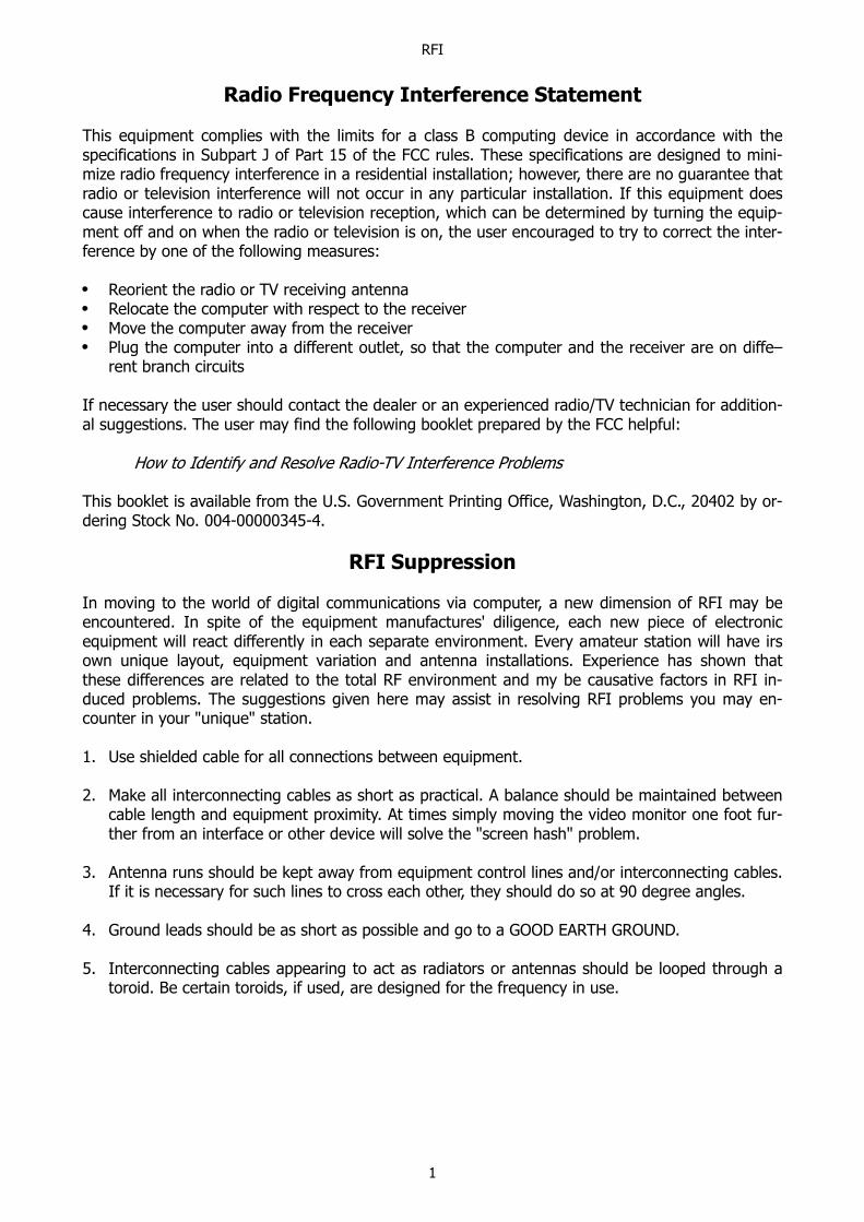
Radio Frequency Interference Statement
This equipment complies with the limits for a class B computing device in accordance with thespecifications in Subpart J of Part 15 of the FCC rules. These specifications are designed to mini-mize radio frequency interference in a residential installation; however, there are no guarantee thatradio or television interference will not occur in any particular installation. If this equipment doescause interference to radio or television reception, which can be determined by turning the equip-ment off and on when the radio or television is on, the user encouraged to try to correct the inter-ference by one of the following measures:
Reorient the radio or TV receiving antennaRelocate the computer with respect to the receiverMove the computer away from the receiverPlug the computer into a different outlet, so that the computer and the receiver are on diffe–rent branch circuits
If necessary the user should contact the dealer or an experienced radio/TV technician for addition-al suggestions. The user may find the following booklet prepared by the FCC helpful:
How to Identify and Resolve Radio-TV Interference Problems
This booklet is available from the U.S. Government Printing Office, Washington, D.C., 20402 by or-dering Stock No. 004-00000345-4.
RFI Suppression
In moving to the world of digital communications via computer, a new dimension of RFI may beencountered. In spite of the equipment manufactures' diligence, each new piece of electronicequipment will react differently in each separate environment. Every amateur station will have irsown unique layout, equipment variation and antenna installations. Experience has shown thatthese differences are related to the total RF environment and my be causative factors in RFI in-duced problems. The suggestions given here may assist in resolving RFI problems you may en-counter in your "unique" station.
1. Use shielded cable for all connections between equipment.
2. Make all interconnecting cables as short as practical. A balance should be maintained betweencable length and equipment proximity. At times simply moving the video monitor one foot fur-ther from an interface or other device will solve the "screen hash" problem.
3. Antenna runs should be kept away from equipment control lines and/or interconnecting cables.If it is necessary for such lines to cross each other, they should do so at 90 degree angles.
4. Ground leads should be as short as possible and go to a GOOD EARTH GROUND.
5. Interconnecting cables appearing to act as radiators or antennas should be looped through atoroid. Be certain toroids, if used, are designed for the frequency in use.

PRECAUTIONS
2
PRECAUTIONS
The TNC is grounded through its connections to your transceiver. Make sure your trans-ceiver is properly grounded and your computer has equal ground potential. Follow thegrounding instructions in your transceiver manual.
Cables provided with the TNC are shielded. If you decide to use other cabling, be certain itis also shielded. We do not recommend the use of unshielded RS-232 ribbon cable in theham shack environment.
Pin 25 of the DB-25 connector on the KAM, KPC-2 and KPC-2400 has 12 volts and shouldnever be connected to your terminal or computer port. Pin 18 in the KPC-2 is used by fac-tory personnel only. Under no circumstances should you connect this pin to your terminalor computer output port.

BACK PANELS
3
Back Panels
KAM
KPC-4
KPC-2
KPC-2400
KPC-1

CONNECT COMPUTER
4
Connecting the TNC to Your Computer
RS-232/TTL Jumper
Jumpers are appropriately labeled on the PC board. Refer to the parts location diagram for help inlocating them. Also refer to the Assembly and Disassembly section for information on obtaining ac-cess to the interior of the TNC.
KAM Jumper K7KPC-4 Jumper K10KPC-2 Jumper K2KPC-2400 Jumper K2KPC-1 Jumper K2
This jumper is provided to change the TNC from RS-232 to TTL operating voltage levels. All TNCsare shipped from the factory in the RS-232 position. If your computer operates at TTL level vol-tages, reposition this jumper prior to placing the TNC in service.
TNC to Computer Connection
The TNC is connected to the serial data port of your computer and a terminal program must beloaded into your computer. The serial port provides a place for data to be sent to or received fromthe TNC. The terminal program is the software which runs in the computer, allowing it to commu-nicate with the TNC. This is also sometimes called a communication program.
A few computer systems include a terminal program on the system diskette or in the initial soft-ware package, usually named COMM, TERM or a similar name which conveys the idea of communi-cating. Some computer system require that a terminal program be obtained separately. Severalsimple terminal programs have been included in the Sample Terminal Programs section to assistyou. In general, any program which allows telephone modem communications with the computerwill be suitable for use with the TNC. A special program will be needed for the display of WEFAXpictures.
There are generally four variables to be set in your terminal program. These are baud rate, parity,word length (also called data bits) and the number of stop bits. If your terminal program providesfor these variables, use the following settings to talk to the TNC:
Baud rate: 300, 600, 1200, 1800, 2400, 4800 or 9600Parity: NoneData bits: 8Stop bits: 1
The 25-pin connector on the back panel of the TNC is for connecting to the computer. (The KPC-4has a 9-pin connector.) When facing the back of the back of the TNC the connector on the rightside is labeled COMPUTER. See page 3 for back panel diagrams.
Cable Wiring
A cable is provided with five pre-wired lines for the connector. You must provide the connector toattach these lines to your computer serial port. In most cases, unless the terminal program youuse requires hardware flow control, you need only connect three of these lines – Transmit Data,Receive Data and Signal Ground. For hardware flow control, also called RTS/CTS handshaking, allfive wires in the provided cable are required.

CONNECT COMPUTER
5
Since there are so many computers on the market, it is impossible to provide interfacing informa-tion on all of them. The following chart shows what pins are used in the TNC by name and numberand the corresponding pin to connect to for the most commonly used computer connectors. Ageneral rule, if you have a computer not covered here that has a serial data port, wire pins of thesame name together. Limited information on some of the other common computers will follow.
Transmit Data (TXD), Receive Data (RXD) and Signal Ground (SG) must always bewired in order for the TNC and the computer to exchange any data. Many terminal pro-grams also require the use of hardware flow control from the TNC. For hardware flowcontrol Request To Send (RTS) and Clear To Send (CTS) must also be wired. Check thedocumentation toyour terminal program to see if any other wires are required. DO NOTCONNECT ALL 25 (9) WIRES.
Some programs want to see Data Set Ready (DSR) to know that the TNC is there before operating.If this is the case, wire both DSR and Data Terminal Ready (DTR). Or sometimes you can satisfythe program's need by jumpering these two pins at the computer end of the cable. Data CarrierDetect (DCD) is needed by some BBS software to know that a connection has taken place. Thiswould require wiring DCD. Some phone modem programs also want to see a connection before al-lowing you to even talk to the TNC. This case can usually be solved by jumpering DCD to DTR atthe computer end of the cable. If your computer requires DSR and also DCD, it is perfectly accept-able to jumper all three pins (DTR, DSR and DCD) together on the computer end of the cable.Note: DCD, DSR and DTR connections are not pre-wired in the provided cable.
The TNC is wired as DCE (Data Communication Equipment). DCE equipment always send its dataon the RXD wire. DTE (Data Terminal Equipment) talks on TXD. This means that, if a computer iswired internally as DCE and attached to the TNC, it will need to have TXD from the computerwired to RXD on the TNC and RXD from the computer wired to TXD of the TNC. Otherwise theywill both be talking on the same wire and never hear what is said. If properly implemented by theDCE computer, hardware flow control may be used by connecting RTS from each device to CTS onthe other device.
Caution: Make sure the power to the transceivers, computer and TNC is OFF before connectingany cables.
CONNECT COMPUTER
6
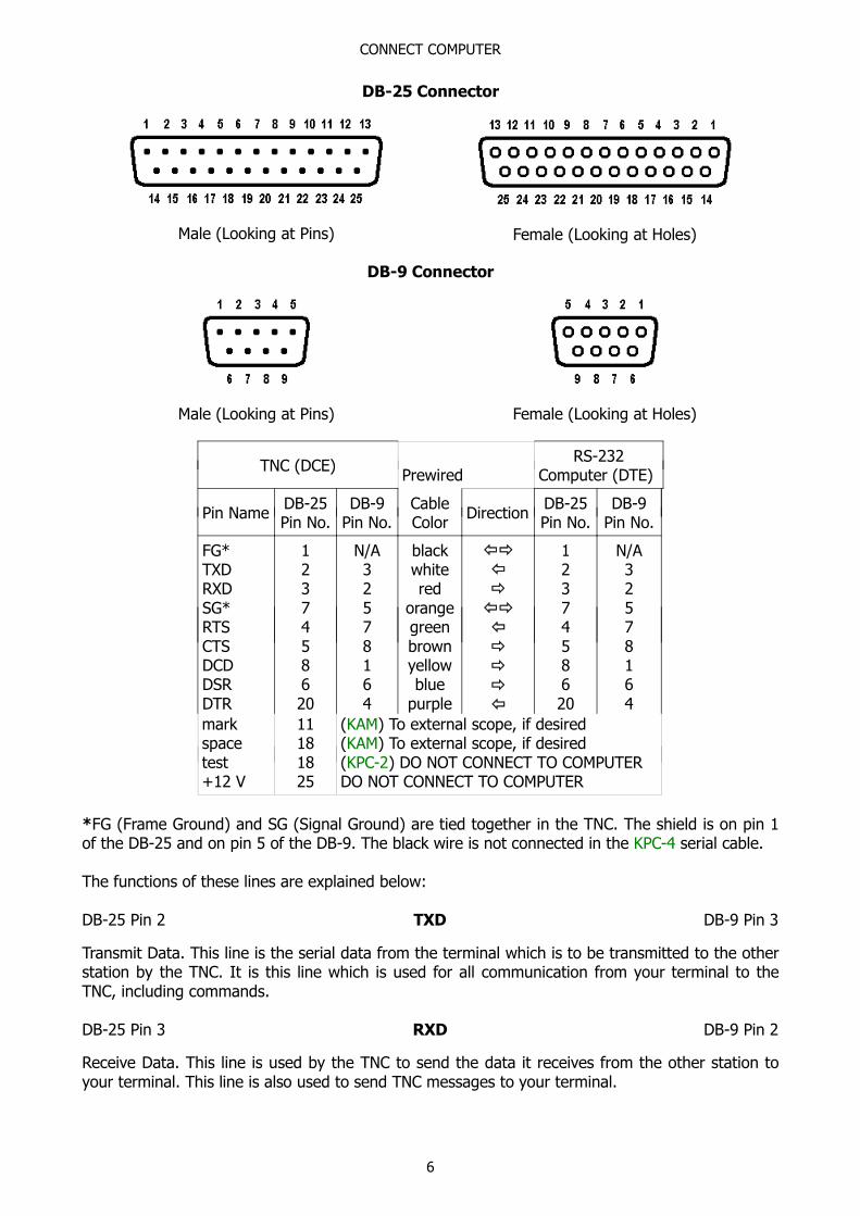
DB-25 Connector
Male (Looking at Pins) Female (Looking at Holes)
DB-9 Connector
Male (Looking at Pins) Female (Looking at Holes)
TNC (DCE)Prewired
RS-232Computer (DTE)
Pin NameDB-25Pin No.
DB-9Pin No.
CableColor
DirectionDB-25Pin No.
DB-9Pin No.
FG*TXDRXDSG*RTSCTSDCDDSRDTR
1237458620
N/A32578164
blackwhitered
orangegreenbrownyellowblue
purple
1237458620
N/A32578164
markspacetest+12 V
11181825
(KAM) To external scope, if desired(KAM) To external scope, if desired(KPC-2) DO NOT CONNECT TO COMPUTERDO NOT CONNECT TO COMPUTER
*FG (Frame Ground) and SG (Signal Ground) are tied together in the TNC. The shield is on pin 1of the DB-25 and on pin 5 of the DB-9. The black wire is not connected in the KPC-4 serial cable.
The functions of these lines are explained below:
DB-25 Pin 2 TXD DB-9 Pin 3
Transmit Data. This line is the serial data from the terminal which is to be transmitted to the otherstation by the TNC. It is this line which is used for all communication from your terminal to theTNC, including commands.
DB-25 Pin 3 RXD DB-9 Pin 2
Receive Data. This line is used by the TNC to send the data it receives from the other station toyour terminal. This line is also used to send TNC messages to your terminal.

CONNECT COMPUTER
7
DB-25 Pins 7 and 1 SG DB-9 Pin 5
Signal Ground. This line establishes the common reference potential for all circuits except ProtectivGround.
DB-25 Pin 4 RTS DB-9 Pin 7
Request To Send. This line tells the TNC that the terminal is ready to receive data. An ON leveltells the TNC it ma send data while an OFF level tells it to stop sending data. If the terminal forany reason is unable to accept data from the TNC, it will cause this line to change to an OFF state,providing that the terminal supports hardware flow control. For instance, buffer is full, terminal isturned off and so on.
DB-25 Pin 5 CTS DB-9 Pin 8
Clear To Send. This line is used by the TNC to tell the terminal whether or not it may send data tothe TNC. AN ON level tells the terminal it may send data while an OFF level tells it to stop sendingdata. This pin is the complement to the RTS pin, implementing hardware flow control in the otherdirection.
DB-25 Pin 8 DCD DB-9 Pin 1
Data Carrier Detect. This line is an output from the TNC indicating connected status of the TNC.When a connection exits on the current stream, this line will be true. (When using TTL levels, DCDat +5 V indicates connected status.) This pin has no function on the KPC-1.
DB-25 Pin 6 DSR DB-9 Pin 6
Data Set Ready. Some terminal programs look at this pin to see that the TNC is operating beforeallowing you to talk to the TNC. This pin is pulled true and is common with DTR, as shipped fromthe factory. In the KPC-1 DSR is jumpered to DTR and is not connected to any internal circuitry.
DB-25 Pin 20 DTR DB-9 Pin 4
Data Terminal Ready. This pin is common with DSR in the TNC. The TNC assumes the terminal isoperating and does not require the terminal to pull this pin true. This pin may be isolated fromDSR if desired. In the KPC-1 DTR is jumpered to DSR and is not connected to any internal circuitry.
DB-25 Pins 11/18 Mark/Space
KAM ONLYMark/Space. These signals are available for connecting an external scope if desired. Refer to theScope Monitoring section for instructions.
DB-25 Pin 18 Test
KPC-2 ONLYProcessor Test Input. This is used by factory personnel only in repair and service operations.UNDER NOR CIRCUMSTANCES should you connect this pin to your terminal or computer outputport.
DB-25 Pin 25 Plus 12 Volts
KAM, KPC-2 and KPC-2400+12 V. This is an alternate input pin for supplying power to the TNC if desired. If the normal+12 VDC input jack is used, this pin will be HOT. BE CERTAIN THIS PIN IS NOT CONNECTED TOYOUR COMPUTER!

CONNECT COMPUTER
8
Other Common Computers
If you have a C-64, C-128, VIC-20, PCjr, Radio Shack Color Computer, TRS Model 100 or an Atari850, some limited information follows. For a description of the functions of the TNC pins refer tothe previous information.
Commodore C-64, C-128 or VIC-20
If you are using an RS-232 adapter follow the previous instructions for Cable Wiring. If you are notusing an RS-232 adapter, remember to change the TNCs RS-232/TTL Internal Jumper fromRS-232 to TTL (see beginning of this chapter). Many programs will only require TXD, RXD and SG.If using hardware flow control, RTS and CTS will also be required.
Commodore User Port24 pin Double-Sided Card Edge Connector
Looking at Back of computer or Back (wiring side) of connector
TNC (DCE) Prewired Commodore
Pin NameDB-25Pin No.
DB-9Pin No.
CableColor
DirectionUser Port (TTL)
Pin ID
TXDRXDSG*RTSCTSDCDDSRDTR
237458620
32578164
whitered
orangegreenbrownyellowblue
purple
MB & C
NDKHLE
markspacetest+12 V
11181825
(KAM) To external scope, if desired(KAM) To external scope, if desired(KPC-2) DO NOT CONNECT TO COMPUTERDO NOT CONNECT TO COMPUTER
PCjr
The IBM PCjr has a built-in terminal program in the basic cartridge. The terminal mode is startedby typing TERM. Consult the PCjr Technical Reference Manual for pin-out requirements for the PCjrserial port. You will have to buy a special connector from your computer dealer for the PCjr.

CONNECT COMPUTER
9
Radio Shack Color Computers
The serial port of the color computer uses a 4-pin DIN plug. Pin connections at the port are shownin the pin table below:
Pin Name TNC DB-25 KPC-4 DB-9 Cable Color TRS CoCo
TXDRXDSG
237
325
whitered
orange
423
This is known as a three-wire interface and therefore requires the use of software flow control.This cabling supports the TRS VIDTEX program. If you have a micro-color computer, such as theMC-10, cabling is different; consult your computer reference manual.
You may also use the Radio Shack Deluxe RS-232 Program Pak. This is a plug-in module for theTRS-80 Color Computer line which is available from Radio Shack Stores.
The Deluxe RS-232 Pak has a standard DB-25 serial port connector to which you connect the TNCusing the following configurations:
Pin Name TNC DB-25 KPC-4 DB-9 Cable Color TRS RS-232
TXDRXDSG
237
325
whitered
orange
237
You must also install a jumper between pin 8 and pin 20 on the DB-25 connector of the DeluxeRS-232 Pak. It is not necessary to connect RTS/CTS lines. Since these lines are not connected, youmust use software flow control. Configure the Deluxe RS-232 Pak as outlined in its operation man-ual, select the Terminal Mode and you will be ready for Packet operation.
TRS Model-100
This computer has a standard RS-232 serial port using a DB-25 connetor wired as DTE. The inter-nal modem program DOES NOT support CTS/RTS hardware flow control. Be sure to have the TNCcommand XFLOW ON so that software flow control (XON/XOFF) will be used. You should make athree-wire cable as follows:
Pin Name TNC DB-25 KPC-4 DB-9 Cable Color TRS-100
TXDRXDSG
237
325
whitered
orange
237
CONNECT COMPUTER
10
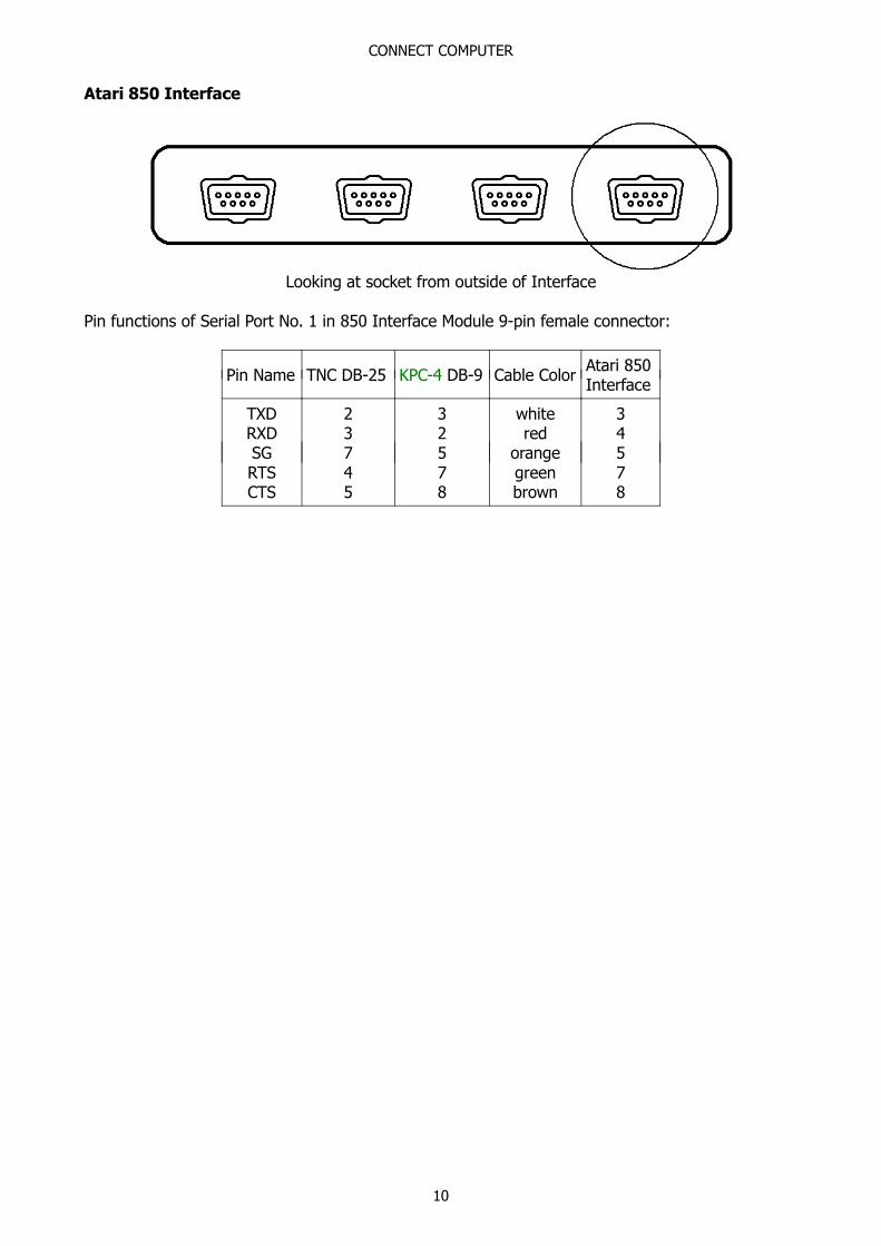
Atari 850 Interface
Looking at socket from outside of Interface
Pin functions of Serial Port No. 1 in 850 Interface Module 9-pin female connector:
Pin Name TNC DB-25 KPC-4 DB-9 Cable ColorAtari 850Interface
TXDRXDSGRTSCTS
23745
32578
whitered
orangegreenbrown
34578

CONNECT RADIOS
11
Connecting Your Radios
The TNC is attached to your transceiver(s) via the radio Connector(s) on the back panel. (Seepage 3 for back panel diagrams.) The KPC-2 and KPC-2400 each have one DB-9 connector labeledRADIO, which is used for either VHF or HF. The KPC-1 has one 5-pin DIN connector labeled RA-DIO, which is used either for VHF or HF. The KAM has a DB-9 connector labeled VHF RADIO andan 8-pin DIN connector labeled HF RADIO. The KPC-4 has two DB-9 connectors for VHF/UHF radioconnections labeled PORT 1 and PORT 2.
Pre-wired cables are provided with the appropriate connector for the TNC port. Two cables comeout of the connector. One with a speaker plug attached, to be plugged into the transceivers exter-nal speaker jack. You will need to provide the mic-jack connector for your transceiver and wire theconnector to the other cable. Lines from this connector are used to control the PTT function of thetransceiver, input AFSK tones from the TNC and provide other alternate Inputs/Outputs asdescribed. The KPC-1 comes with two separate cables. One for audio with speaker plugs on bothends. The other cable has a 5-pin DIN connector on the end for the KPC-1 and you will need toprovide the mic-jack connector for your transceiver and wire it to the other end of this cable.
Some rados may require adjustment of the AFSK Output Levels or Equalization of the received sig-nals. See the AFSK Output Level and Calibration/Equalization sections for information.
Caution: Check your transceiver manual to correctly wire the corresponding pins of the transceivermic-jack.
DB-9 Radio Connector
Male (Looking at Pins) Female (Looking at Holes)
Pins 1, 3, 5 and 6 must be connected to your radio.
Pin 1 – AFSK Out – white leadThis lines carries the AFSK tones generated by the TNC to the Audio Input (microphone) line ofyour transceiver. If your transceiver provides a DC voltage on its microphone input, you must iso-late this voltage from the TNC. This is normally true for hand-held radios. (See the InterfacingHand-Held Radio section.)
Pin 2 – XCD – yellow leadThis line may be used to connect the squelch line from your VHF transceiver if desired. This con-nection will not normally be required, nor used, unless operating on a shared voice channel. Nor-mally the TNC detects other signals by using its internal software to determine if data is present. Ifthis pin is connected, a ground potential on this pin will tell the TNC that a signal is present (evenif there is no data) and therefore prevent the TNC from transmitting until the signal is no longerpresent. (See the CD parameter in the Commands Manual.)
Pin 3 – Push-To-Talk – brown leadThis line controls the PTT line in your transceiver, allowing the computer to switch the transceiverfrom/to transmit or receive. Connect directly to the PTT line of the mic-jack connector (See thesection on Interfacing Hand-Held Radios for special notes concerning this pin.)
CONNECT RADIOS
12
Pin 4 – Blue lead – KAM same as pin 5KPC-4, both ports, same as pin 5KPC-2 same as pin 6KPC-2400 has no connection
Pin 5 – Audio Signal – 2 conductor audio cable, center conductor and 9-wire cable, purple conduc-tor
This line is prewired for your use as the audio input from your transceiver external speaker jack.Do not use a headphone output from the transceiver. If you use an accessory or phone patch out-put, it may be necessary to provide a padding network to reduce amplitude of the signal being fedto the TNC. High level fixed outputs may have a tendency to "swamp" the TNC input circuits. Fixedoutput signals in excess of 50 mV should be padded.
For the KAM and KPC-4 you can plug this lead into one leg of the Y-connector cable provided inthe TNC accessory bag. Plug the Y-connector cable into the external speaker jack of the trans-ceiver. The remaining female connector on the Y-connector cable may be used for an externalspeaker. For the KPC-2 and KPC-2400 the audio jack on the back panel remains available for at-tachment of an external speaker.
Pin 6 – Ground/Shield – shield of 9-wire cable and shield of audio cableConnect the push-to-talk ground and AFSK shield to this line. With some transceivers which do notreference PTT and audio shielding to a common ground, it may be necessary to leave the AFSKshield (braided wire) disconnected. NOTE: All TNC grounds are common.
Pin 7 – KPC-4 Radio Port 1 External Reset – red leadAn external reset line is provided on this pin. Applying a ground, either from a local or remotesource is the same as turning on the TNC. This is only on the KPC-4 Radio Port 1.
Pin 8 – Green lead – KAM same as pin 6KPC-4, both ports, same as pin 6KPC-2 no connectionKPC-2400 no connection
Pin 9 – Ground – Black lead – same as pin 5
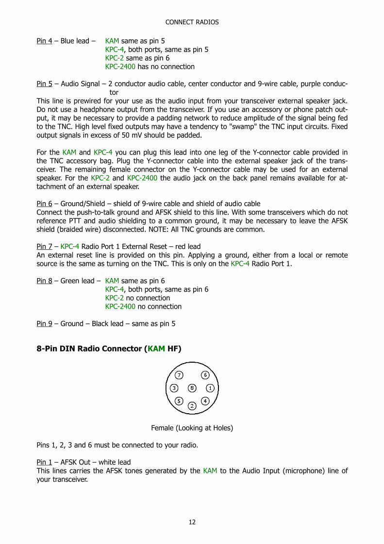
8-Pin DIN Radio Connector (KAM HF)
Female (Looking at Holes)
Pins 1, 2, 3 and 6 must be connected to your radio.
Pin 1 – AFSK Out – white leadThis lines carries the AFSK tones generated by the KAM to the Audio Input (microphone) line ofyour transceiver.
CONNECT RADIOS
13
Pin 2 – Ground/Shield – black and shield of 9-wire cable and shield of audio cableConnect the push-to-talk ground and AFSK shield to this line. With some transceivers which do notreference PTT and audio shielding to a common ground, it may be necessary to leave the AFSKshield (braided wire) disconnected. NOTE: All TNC grounds are common.
Pin 3 – Push-To-Talk – brown leadThis line controls the PTT line in your transceiver, allowing the computer to switch the transceiverfrom/to transmit or receive. Connect directly to the PTT line of the mic-jack connector.
Pin 4 – Key Out – orange leadThis line may be used to control CW keying on your transceiver. Separate a small length of thislead and attach a lead with the appropriate plug for your transceiver key jack, where you wouldnormally connect a straight key.
Pin 5 – FSK Out – red leadThis line is for use if your transceiver provides FSK keying for RTTY operation. Separate a smalllength of this lead and attach a lead with the appropriate plug for your FSK input connector on thetransceiver. It will also be necessary to provide for PTT keying via the mic jack, accessory port orother method specified by your transceiver manual.
Pin 6 – Audio signal – 2 conductor audio cable, center conductor and 9-wire cable, purple conduc-tor
Plug this lead to one leg of the Y-connector cable provided in the KAM accessory bag. Plug the Y-connector cable into the external speaker jack of the transceiver. The remaining female connectoron the Y-connector may be used for an external speaker. Do not use a headphone output from thetransceiver. If you use an accessory or phone patch output, it may be necessary to provide a pad-ding network to reduce amplitude of the signal being fed to the KAM. High level fixed outputs mayhave a tendency to "swamp" the KAM input circuits. Fixed output signals in excess of 50 mVshould be padded.
Pin 7 – Blue leadThis pin is not connected in the KAM but the blue conductor of the 9-wire cable is attached to thispin.
Pin 8 – XCD – yellow leadThis line may be used to connect the squelch line from your HF transceiver if desired. This connec-tion will not normally be required, nor used, unless operating on a shared voice channel. (See theCD parameter in the Commands Manual.)
CONNECT RADIOS
14
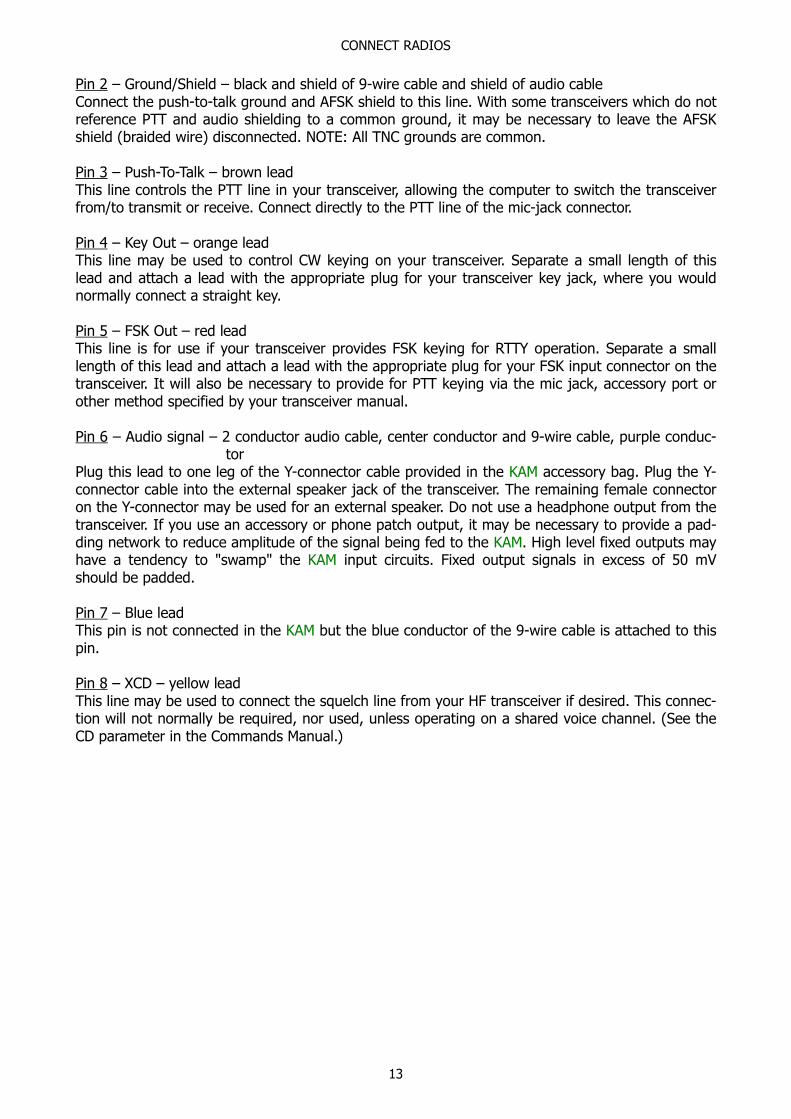
5-Pin DIN Radio Connector (KPC-1 Packet Communicator)
Female (Looking at Holes)
Pins 1, 2, 3 and Audio In must be connected to your radio.
Pin 1 – AFSK Out – white leadThis lines carries the AFSK tones generated by the TNC to the Audio Input (microphone) line ofyour transceiver. If your transceiver provides a DC voltage on its microphone input, you must iso-late this voltage from the TNC. This is normally true for hand-held radios. (See the InterfacingHand-Held Radio section.)
Pin 2 – Ground/Shield – black and stranded leadConnect the push-to-talk ground and AFSK shield to this line. With some transceivers which do notreference PTT and audio shielding to a common ground, it may be necessary to leave the AFSKshield (braided wire) disconnected. NOTE: All TNC grounds are common.
Pin 3 – Push-To-Talk – brown leadThis line controls the PTT line in your transceiver, allowing the TNC to switch the transceiverfrom/to transmit or receive. Connect directly to the PTT line of the mic-jack connector (See thesection on Interfacing Hand-Held Radios for special notes concerning this pin.)
Audio inAttach a cable from the external speaker jack of the transceiver to the Audio In jack on the rearpanel of the Packet Communicator. Do not use a headphone or phone patch output from yourtransceiver.
External Speaker JackThis jack can be used to loop the audio through the Packet Communicator. Use a 3.5 mm plug andshielded audio cable to connect to an external speaker.

AFSK OUTPUT LEVEL
15
AFSK Output LevelAudio Frequency Shift Keying
Jumpers are appropriately labeled on the PC board. Refer to the parts location diagram for help inlocating them. Also refer to the Assembly and Disassembly section for information on obtaining ac-cess to the interior of the TNC.
KAM – AFSK Output – VHF – Jumper K2
This jumper is provided to alter the VHF AFSK output level. The KAM is shipped from the factorywith the jumper in the LO position. The LO position sets an AFSK output level from the KAM at10 mV. The HI position sets an AFSK output level of 50 mV. Both levels are peak-to-peak values. Ingeneral, transceivers requiring a pre-amplified microphone will also require the HI level AFSK out-put from the KAM. Removing the jumper entirely will provide the maximum possible output level ofapproximately 1.7 Vpp. Should you require an intermediate value of AFSK modulation signal, itmay be obtained by replacing resistor R12 with the appropriate value chosen from the followingchart. If you change R12 to obtain an intermediate value, place K2 in the HIGH position.
R12 Value AFSK Output Level
470 Ω2.2 kΩ6.8 kΩ22 kΩ47 kΩ
24 mV106 mV290 mV680 mV1000 mV
KAM – AFSK Output – HF – Jumper K5
This jumper is provided to alter the HF AFSK output level. The KAM is shipped from the factorywith the jumper in the LO position. The LO position sets an AFSK output level from the KAM at100 mV. The HI position sets an AFSK output level of 500 mV. Both levels are peak-to-peak values.In general, transceivers requiring a pre-amplified microphone will also require the HI level AFSKoutput from the KAM. Removing the jumper entirely will provide the maximum possible output lev-el of approximately 1.6 Vpp. Should you require an intermediate value of AFSK modulation signal,it may be obtained by replacing resistor R25 with the appropriate value chosen from the followingchart. If you change R25 to obtain an intermediate value, place K5 in the HIGH position.
R25 Value AFSK Output Level
680 Ω3.3 kΩ4.7 kΩ6.8 kΩ22 kΩ
48 mV209 mV282 mV377 mV800 mV
AFSK OUTPUT LEVEL
16
KPC-4 – AFSK Output – Jumpers K3 and K4
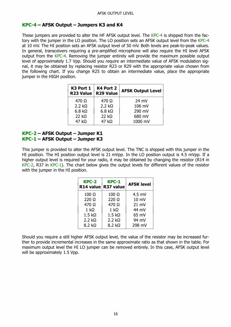
These jumpers are provided to alter the HF AFSK output level. The KPC-4 is shipped from the fac-tory with the jumper in the LO position. The LO position sets an AFSK output level from the KPC-4at 10 mV. The HI position sets an AFSK output level of 50 mV. Both levels are peak-to-peak values.In general, transceivers requiring a pre-amplified microphone will also require the HI level AFSKoutput from the KPC-4. Removing the jumper entirely will provide the maximum possible outputlevel of approximately 1.7 Vpp. Should you require an intermediate value of AFSK modulation sig-nal, it may be obtained by replacing resistor R23 or R29 with the appropriate value chosen fromthe following chart. If you change R25 to obtain an intermediate value, place the appropriatejumper in the HIGH position.
K3 Port 1R23 Value
K4 Port 2R29 Value
AFSK Output Level
470 Ω2.2 kΩ6.8 kΩ22 kΩ47 kΩ
470 Ω2.2 kΩ6.8 kΩ22 kΩ47 kΩ
24 mV106 mV290 mV680 mV1000 mV
KPC-2 – AFSK Output – Jumper K1KPC-1 – AFSK Output – Jumper K3
This jumper is provided to alter the AFSK output level. The TNC is shipped with this jumper in theHI position. The HI position output level is 21 mVpp. In the LO position output is 4.5 mVpp. If ahigher output level is required for your radio, it may be obtained by changing the resistor (R14 inKPC-2, R37 in KPC-1). The chart below gives the output levels for different values of the resistorwith the jumper in the HI position.
KPC-2R14 value
KPC-1R37 value
AFSK level
100 Ω220 Ω470 Ω1 kΩ
1.5 kΩ2.2 kΩ8.2 kΩ
100 Ω220 Ω470 Ω1 kΩ
1.5 kΩ2.2 kΩ8.2 kΩ
4.5 mV10 mV21 mV44 mV65 mV94 mV298 mV
Should you require a still higher AFSK output level, the value of the resistor may be increased fur-ther to provide incremental increases in the same approximate ratio as that shown in the table. Formaximum output level the HI LO jumper can be removed entirely. In this case, AFSK output levelwill be approximately 1.5 Vpp.
AFSK OUTPUT LEVEL
17
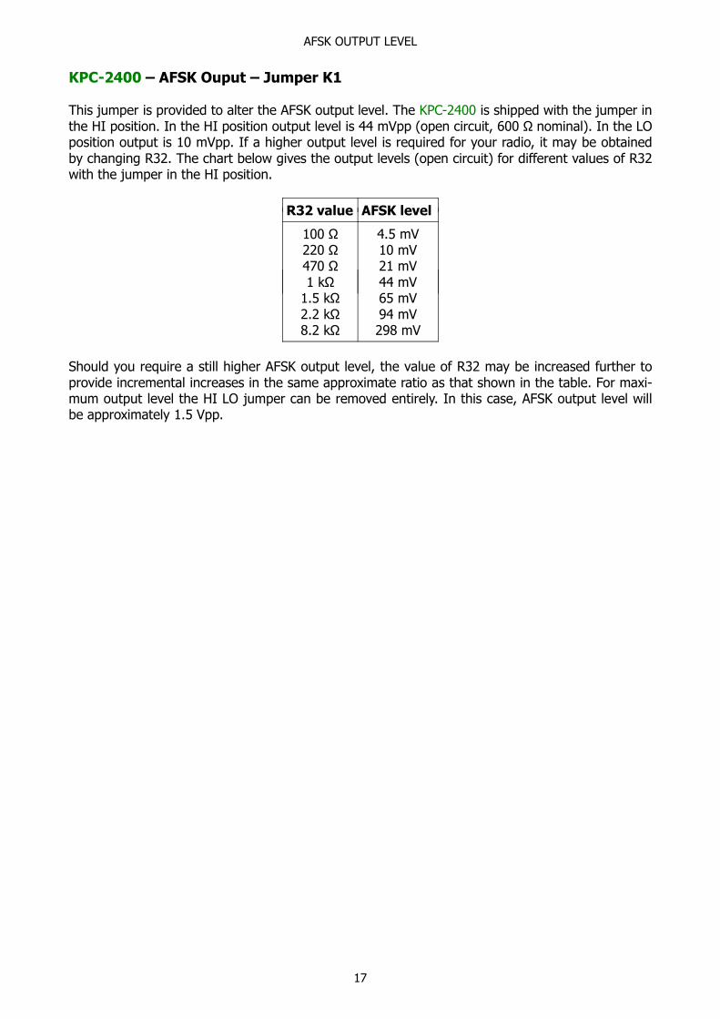
KPC-2400 – AFSK Ouput – Jumper K1
This jumper is provided to alter the AFSK output level. The KPC-2400 is shipped with the jumper inthe HI position. In the HI position output level is 44 mVpp (open circuit, 600 Ω nominal). In the LOposition output is 10 mVpp. If a higher output level is required for your radio, it may be obtainedby changing R32. The chart below gives the output levels (open circuit) for different values of R32with the jumper in the HI position.
R32 value AFSK level
100 Ω220 Ω470 Ω1 kΩ
1.5 kΩ2.2 kΩ8.2 kΩ
4.5 mV10 mV21 mV44 mV65 mV94 mV298 mV
Should you require a still higher AFSK output level, the value of R32 may be increased further toprovide incremental increases in the same approximate ratio as that shown in the table. For maxi-mum output level the HI LO jumper can be removed entirely. In this case, AFSK output level willbe approximately 1.5 Vpp.

HAND-HELDS
18
Interfacing Hand-Held Radios
Many transceivers, especially most hand-held models, obtain Push-To-Talk keying by completing acircuit between the mic input and PTT ground. A direct PTT input to the mic input line of units withthis type electret condenser microphone is not usable without some type of isolation.
If you plan to operate with a hand-held transceiver, the KAM, KPC-2 and KPC-4 have incorporatedan isolation circuit which is available by jumper positioning. Should you later use a different typeradio, this change may need to be reconfigured. Most other radios of current manufacture will notrequire any modification of the TNC.
You may also interface to a hand-held without performing this modification by incorporating thesame type of circuitry in the cable from your TNC to your hand-held. Ground return and speakeraudio are both supplied thru the external speaker jack of your hand-held.
ICOM HT radios key the PTT by providing a low impedance path from the mic input to ground. Toaccomplish this, simply install a resistor (approximately 3.9 k seems to be a good value) in serieswith the PTT wire from the TNC and connect this to the mic input along with the AFSK line.
ICOM Mic Connector
YAESU radios are similar but use a mono plug and a different resistor-
YAESU Mic Connector
Most KENWOOD HT radios key the PTT line by connecting the sleeve of the mic connector to thesleeve of the earpiece connector. This means, that you will not need a resistor in the PTT wirefrom the TNC, simply connect the PTT wire to the sleeve of the mic connector. Another point towatch – most of the KENWOOD HTs (2500 and later) use a three pin mic connector. The AFSKfrom the TNC should therefore connect to the RING and not the TIP of the mic connector.
KENWOOD Mic Connector
HAND-HELDS
19
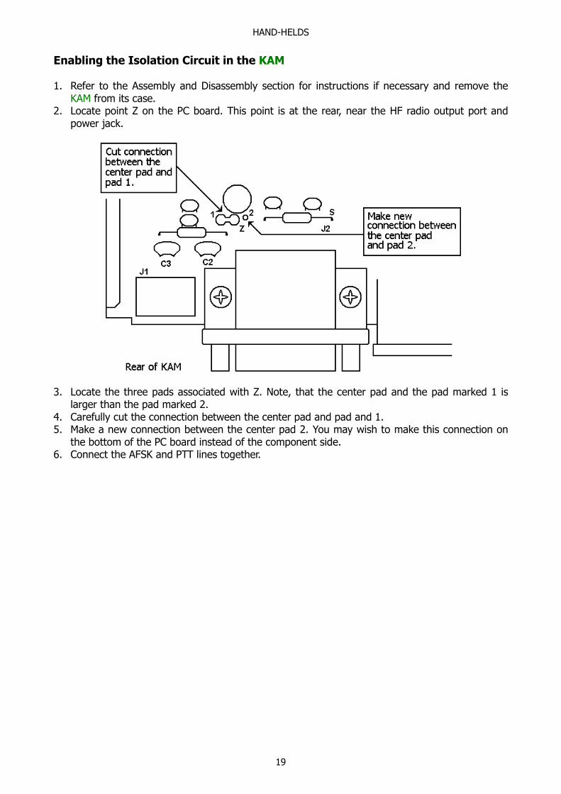
Enabling the Isolation Circuit in the KAM
1. Refer to the Assembly and Disassembly section for instructions if necessary and remove theKAM from its case.
2. Locate point Z on the PC board. This point is at the rear, near the HF radio output port andpower jack.
3. Locate the three pads associated with Z. Note, that the center pad and the pad marked 1 islarger than the pad marked 2.
4. Carefully cut the connection between the center pad and pad and 1.5. Make a new connection between the center pad 2. You may wish to make this connection on
the bottom of the PC board instead of the component side.6. Connect the AFSK and PTT lines together.
HAND-HELDS
20
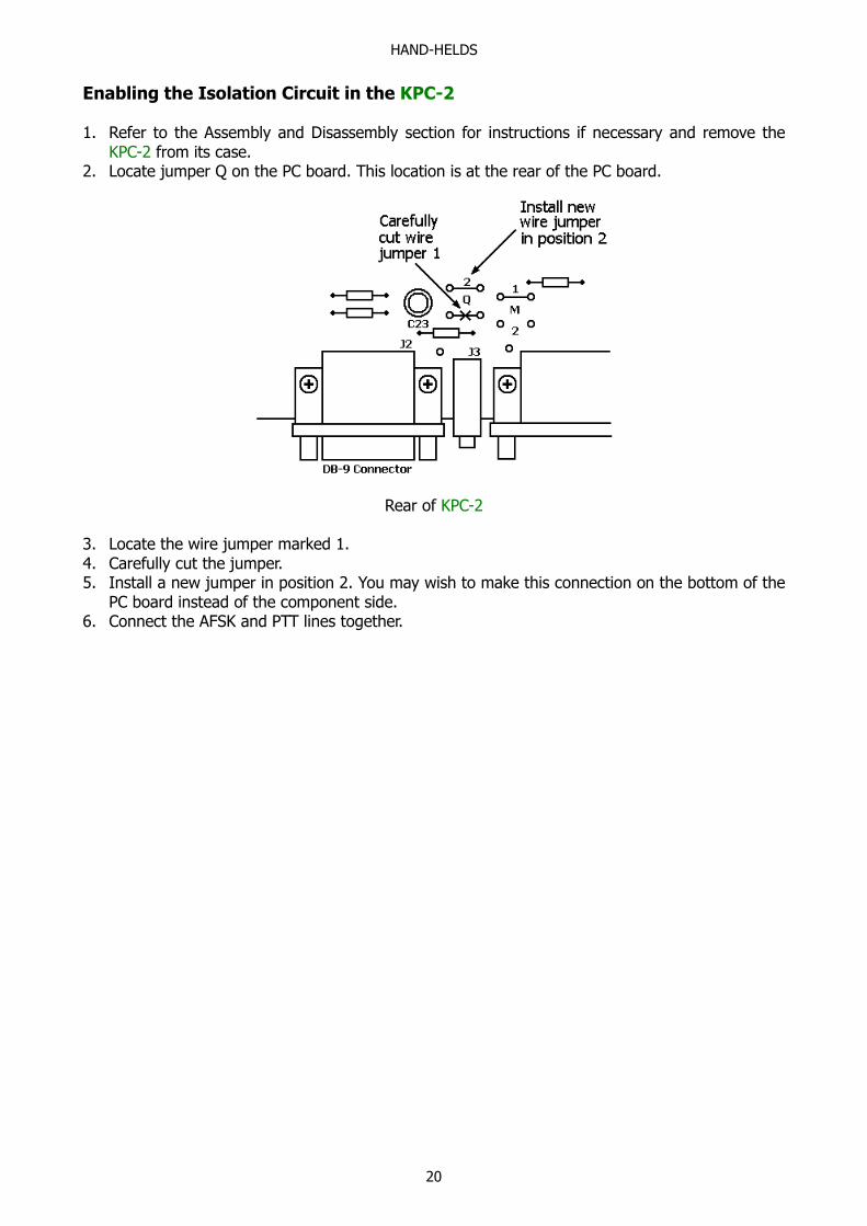
Enabling the Isolation Circuit in the KPC-2
1. Refer to the Assembly and Disassembly section for instructions if necessary and remove theKPC-2 from its case.
2. Locate jumper Q on the PC board. This location is at the rear of the PC board.
Rear of KPC-2
3. Locate the wire jumper marked 1.4. Carefully cut the jumper.5. Install a new jumper in position 2. You may wish to make this connection on the bottom of the
PC board instead of the component side.6. Connect the AFSK and PTT lines together.
HAND-HELDS
21
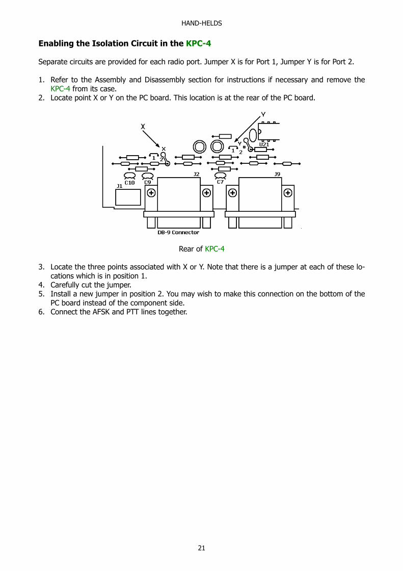
Enabling the Isolation Circuit in the KPC-4
Separate circuits are provided for each radio port. Jumper X is for Port 1, Jumper Y is for Port 2.
1. Refer to the Assembly and Disassembly section for instructions if necessary and remove theKPC-4 from its case.
2. Locate point X or Y on the PC board. This location is at the rear of the PC board.
Rear of KPC-4
3. Locate the three points associated with X or Y. Note that there is a jumper at each of these lo-cations which is in position 1.
4. Carefully cut the jumper.5. Install a new jumper in position 2. You may wish to make this connection on the bottom of the
PC board instead of the component side.6. Connect the AFSK and PTT lines together.

IN CASE OF DIFFICULTY
22
In Case of Difficulty
Kantronics TNCs are manufactured to very stringent quality standards. If you have followed the in-stallation procedures outlined in this manual, it is highly unlikely that you will encounter a failure.If you do have difficulty, use the procedures described in this section to assist in isolating and cor-recting the problem.
TNC Does Not "Sign-On" to Computer
1. Carefully recheck cabling between your computer serial port and the TNC.2. Check carefully to insure the Transmit Data, Receive Data and Ground leads are connected to
the proper pins.3. If you have made a 5 wire connection to the computer serial port, change to a 3 wire connec-
tion.4. Check your terminal program to be certain it is booted with the correct communications param-
eters (serial port, baud rate, parity).5. Check to insure that the RS-232/TTL jumper is properly positioned for your computer.6. Try a "Hard Reset" using the Test/Normal jumper. (Operate your terminal program at 300 baud
when performing a hard reset.)
You Are Unable to Make a "Connect"
1. Issue a connect request and observe the XMIT LEDs. If an XMIT LED illuminates, check to in-sure that the radio is connected to the corresponding radio port.
2. Observe the radio to determine if it is being switched to the "Transmit" condition. If not, re-check wiring between the TNC radio port, PTT pin and ground on the microphone jack.
3. Turn the VHF radio squelch control to "OFF" and see if the RCV LED illuminates an the Packetcontroller. If it does not light, recheck the audio connection between your transceiver and theTNC.
4. If possible, monitor your transmitted signal with another radio. If the transmitter is keying to"Transmit" but weak or no audio is monitored, increase AFSK output as necessary using theAFSK Output jumper or resistor change. (SEE the AFSK Output Level section.)
Cannot Transmit on Any Port
1. Check the 8BITCONV command. Many dumb terminals, and some Commodore programs, willnot operate properly with this command turned ON. The symptoms most common for thisproblem are, that everything seems to work fine in Command Mode, but upon entering Con-verse Mode, the TNC no longer seems to operate at all. Usually you cannot return to CommandMode with a Ctrl-C, pressing return does not send a packet and it just seems like the serial ca-ble between your computer and TNC has been unplugged.
2. Check your PARITY setting in the computer and in the TNC. These must match or else thecomputer may not really be sending the SENDPAC character ($0D) to the TNC.
Cannot Return to Command Mode
1. The single most common cause of this is, that the STOP character (and usually XOFF) havebeen inadvertently set to the same as the COMMAND character. This is usually caused by theuse of the dollar sign ($) as a streamswitch. If you use the $, be aware that you cannot enterhex values without PASSing the dollar sign. Symptoms for this usually are, that you can talk tothe TC fine in Command Mode, you can usually talk to others on the air, but you just can't getback to Command Mode. (In non-packet modes, you will find that you cannot enter any of thespecial Ctrl-C directives either!) With most PC terminal programs, pressing Ctrl-C will displaythe heart character, but you still don't get the cmd: prompt.

IN CASE OF DIFFICULTY
23
Kanterm Program Problems
1. The most common problems reported with the Kanterm program result from not performingthe Set Parameters option from within the program. This usually occurs after upgrading yourTNC to a new version of the Kantronics firmware. The cause for this is the need to do a HardReset after installing the new firmware and as a result, the TNC and your Kanterm program areno longer "in sync" with each other.
2. Commodore users will normally experience this problem when first setting the TNC up withtheir Kanterm Software. All lower case characters are hidden, only numbers and punctuationappears. In reality, The TNC did receive the proper callsign and you can correct your display bychoosing the Set Parameters option from the Miscellaneous Menu.
TNC Won't Transmit on HF – VHF is OK
This problem usually is a result of attempting to switch from one port to the other by using thePORT command. The PORT command only determines which port will be the default when theTNC is first turned on, or after a reset. In order to switch from one port to the other for transmit-ting data, you must use the STREAMSW characters as described in Multi-Connects in the Packetsection of the Operations Manual.

ASSEMBLY / DISASSEMBLY
24
Assembly and Disassembly of the TNC
Should you require access to the TNC to reposition jumpers or for other purposes, disassemble asfollows:
1. Turn off power to your TNC and remove all cables from he unit.
2. Using a small phillips screwdriver, remove the two front panel screws just far enough to freethe panel and bezel.
3. Carefully remove the front panel and bezel.
4. Note the screw holding the voltage regulator to the metal case. Remove this screw. (Does notapply to KPC-4.)
5. Slide the PC board out of the case.
To reassemble, reverse the procedure above. Be sure to re-install the screw holding the voltageregulator to the case (not in KPC-4). Failure to do so will damage the unit as the case provides aheat sink for the voltage regulator during normal operation. Do not attach cables to the rear of theTNC without supporting the front of the PC board or having the front panel secured in place. Doingso may break the voltage regulator secured to the front of the case.

HARD RESET
25
Hard Reset
The hard reset process is provided to re-initialize the TNC to its default values. This process maybecome necessary should operational problems be encountered or when upgrading your firmwareto a newer version. The readout specified in step 5 below will be legible only if your terminal baudrate is 300. At other terminal baud rates, a reset will occur. However, no display readout will ob-served. This procedure is performed as follows:
1) Remove the PC board from the case as outlined in the Assembly and Disassembly section,above.
2) Locate the Text/Normal jumper which is labeled NOR T (normal-test). Jumpers are appropri-ately labeled on the PC board. Refer to the parts location diagram for help in locating them.
KAM Jumper K6KPC-4 Jumper K7KPC-2 Jumper K3KPC-2400 Jumper K3
3) Place the jumper in the test position.4) Apply power to the TNC.5) Observe on the computer display (your terminal program must be set at 300 baud):
EEPROM INIT OK
CHECKSUM OK
RAM OK XXXXX BYTES
REPLACE TEST JUMPER
Some TNCs will not display the REPLACE message.
If you have removed the 2404 EEPROM from your unit for any reason, the EEPROM INIT mes-sage will read: EEPROM INIT ERROR
This is a normal indication and does not indicate a failure with your TNC.
6) Turn power off. Do not keep the TNC power on for more than a minute or the regulator willoverheat.
7) Return Test/Normal jumper to the normal position.8) Reassemble the TNC and return to operation.
CALIBRATION / EQUALIZATION
26
Calibration / Equalization
The CALIBRATE command is used to assist the TNC operator in determining the need for equaliza-tion of a received signal. Since this feature is unique to Kantronics TNCs, two stations using Kant-ronics TNCs are necessary to utilize this command.
KAM you must have your current I/O stream on the VHF radio port.
KPC-4 uses current I/O port (will not work with an external modem.)
KPC-2 The HF, HFT and CCITT commands should be OFF. Calibration is checked at 1200 baud only.
KPC-1 Tones are transmitted and received at the HBAUD setting and the frequency is specified bythe HF and HFT command settings.
KPC-2400 Tones are transmitted and received at the HBAUD setting and the frequency is specifiedby the HF, HFT and CCITT command settings. However, calibration cannot be done at the HBAUDsetting of 2400.
Once the CALIBRATE command is given, three options will appear on he terminal screen:
Calibrate Mode Press R,T, or X
Pressing X will return the TNC to the Command Mode.
Pressing T will transmit a square wave (space/mark) at the selected tones until a key is pressed.
Pressing R will measure a square wave received.
One station should be used to transmit the square wave, while the receiving station should meas-ure and compare the space/mark square wave. The transmitting station should set the microphonelevel in mid range.
Once the receiving TNC is placed in the CALIBRATE receive mode, two numbers will appear on thescreen. The TNC is measuring the the space/mark square wave generated by the transmitting sta-tion. For the best calibration of the receiving transceiver, set the radio tone controls so that thetwo given values are as close to equal as possible.
In most instances when the ratio of the numbers is within a 40/60 or 60/40 range, the Packet sta-tion will function normally. A larger disparity in the tones may cause additional retries duringPacket operation. This ratio may be determined by the following formula:
(N1 × 100) / (N1 + N2) where N1 is the number to the left of the displayed slash and N2 is to theright of the slash. For instance, if the TNC displays 1400/1800, the ratio can determined by:
(1400 × 100) / (1400 + 1800) or 140000/3200 = 44
Since the total is 100, the ratio is then 44/56 and is within the 40/60 criteria.
KPC-1, KPC-2 and KPC-2400. If the ratio of the numbers exceeds 60/40, you should change thesetting of the equalization command (EQUALIZE). Use the setting (ON or OFF) which results in theratio closest to 50/50.
KAM and KPC-4. If the ratio of the numbers exceeds 60/40, you should reset the internal Equaliza-tion jumper(s) for partial equalization. If, with partial equalization these numbers are still outsidethe 60/40 ratio, set the Equalization jumper for NO equalization.

CALIBRATION / EQUALIZATION
27
Jumpers are appropriately labeled on the PC board. Refer to the parts location diagram for help inlocating them. Also refer to the Assembly and Disassembly section for information on obtaining ac-cess to the interior of the TNC.
KAM Jumper K1VHF-Equalization – This jumper is provided to alter the equalization characteristics of the VHF mo-dem. The KAM is shipped with the jumper placed on ONLY ONE of the posts effectively "OFF" sothat full equalization is in effect. With no jumper installed on the 3-pin header, full equalization is ineffect. With the jumper connecting the center post and the post marked 1, there is no equaliza-tion. With the jumper connecting the center post and post marked 2, partial equalization is in ef-fect. testing has shown, that most VHF transceivers require that the input audio signal de fullyequalized for best performance. Should you wish to operate the KAM in a hard wire Packet line, noequalization should be in effect.
KPC-4 Jumpers K1 (Port 1) and K2 (Port 2)
Equalization – These jumpers are provided to alter the equalization characteristics of the modems.The KPC-4 is shipped with the jumper placed on ONLY ONE of the posts, effectively "OFF", so thatfull equalization is in effect. With no jumper installed on the 3-pin header, full equalization is in ef-fect. With the jumper connecting the center post and the post marked 1, there is no equalization.With the jumper connecting the center post and the post marked 2, partial equalization is in effect.testing has shown that most VHF/UHF transceivers require that the input audio by fully equalizedfor best performance. Should you wish to operate the KPC-4 in a hard wire Packet line, no equal-ization should be in effect.

WATCH DOG TIMERS
28
Watch Dog Timers
Jumpers are appropriately labeled on the PC board. Refer to the parts location diagram for help inlocating them. Also refer the Assembly and Disassembly section for information on obtaining ac-cess to the interior of the TNC.
KAM – VHF Timer – Jumper K3
This jumper is provided to disable to disable the VHF watch dog timer. The timer is disabled if thejumper is installed. Time-out of the KAM will occur after approximately 2.5 minutes, un-keying theVHF PTT line. The KAM is shipped with the jumper not connecting the jumper posts; therefore, thetimer is in effect.
KAM – HF Timer – Jumper K4
This jumper is provided to disable to disable the HF watch dog timer. The timer is disabled if thejumper is installed. Time-out of the KAM will occur after approximately 2.5 minutes, un-keying theHF PTT line. The KAM is shipped with the jumper installed; therefore, the timer is not in effect.
KAM Operating Note
As shipped from the factory, the VHF watch dog timer is in effect and the HF watch dog timer isnot. The HF timer is not enabled since it cannot distinguish between RTTY and Packet signals.Should you plan to operate a mode other than Packet, the HF timer will limit your transmission toapproximately 2.5 minutes if it is enabled.
KPC-4 – Timers – Jumpers K5 (Port 1) and K6 (Port 2)
These jumpers are provided to disable the watch dog timers. The timer is disabled if the jumper isinstalled. Time-out of the KPC-4 will occur after approximately 2.5 minutes, un-keying the PTT line.The KPC-4 is shipped with the jumpers not connecting the jumper posts; therefore, the timers arein effect. Should you wish to have a SHORTER timer interval, it may be obtained by changing theappropriate resistor shown in the following chart:
K5 Port 1 K6 Port 2 Time Delay Rsistor Value
R43R43R43
R44R44R44
1.25 min.75 min.5 min
470 kΩ220 kΩ2.2 MΩ
KPC-2400
The KPC-2400 is shipped with the Optional Watch Dog circuit board installed. (This applies to unitsafter serial number 73400. An optional circuit board may be ordered from Kantronics for units withserial numbers before 73400 and should be installed for digipeater or unattended operation.)
K1 jumper on both pins disables watch dog circuit. If harness is unplugged from watch dog boarda 2.2 kΩ 5 % ¼ Watt resistor MUST be inserted between pins 1 and 5 wiring harness connector toallow normal operation. WARNING: A resistor larger than ¼ Watt will damage the connector. PTTshut-off time is approximately 2 minutes.
KPC-1 and KPC-2
These TNCs do not come with a watch dog timer installed. An optional circuit board may be or-dered from Kantronics and should be installed for digipeater or unattended operation.

SCOPE MONITORING
29
Scope MonitoringKAM only
Obtaining Mark and Space Outputs
The schematic diagram of the KAM indicates that Mark and Space outputs are available on pins 11and 18 of J4 (DB-25 connector). Provisions have been made for obtaining these outputs AFTER in-stalling jumpers between the points provided on the PC board. This is accomplished by locatingthe four holes in the board marked MA and SP and adding wire jumpers between them. One pairof holes marked MA and SP are located next to the DB25 connector (J4) and the other pair is lo-cated on the opposite end of the board. Install jumpers from MA to MA and SP to SP andMark/Space signals will then be present at pins 11 and 18 of J4. It is advisable to install a 100 kΩresistor in series with these lines to protect the KAM from external voltages.

DUMB MODEM MODE
30
Dumb Modem ModeKPC-1, KPC-2 and KPC-2400 Only
The TNC can also be used as a straight-through or dumb modem. In this mode the TNC does notuse any of the protocols or special characteristics of Packet-Radio. Instead, the TNC simply outputsany information sent through the RS-232/TTL port, at up to 1200 baud.
To utilize the dumb feature, you must PERM the MODEMENA parameter ON. Hold the RTS line ofthe RS-232 connector at a negative voltage when the TNC is powered on. If the connector is set tothe TTL level position, the RTS line must be held at a positive 5 volts when the TNC is powered on.
To operate in the dumb modem mode you must utilize the RTS and CTS lines. The TNC will func-tion as a true RS-232 device, using these lines to control transmit and receive operation. Thetransmit and receive LED on the front panel will be operational. This mode uses the PERMed pa-rameters as specified by the HF, HFT and CCITT command and checks the status of the EQUALIZEparameter.
To exit this mode, you must turn the TNC off and power up with RTS free.
LOOP-BACK TEST
31
Performing a Loop-Back TestKPC-4 Only
This test is to verify that your KPC-4 is functional and that the wiring to your computer is correct.
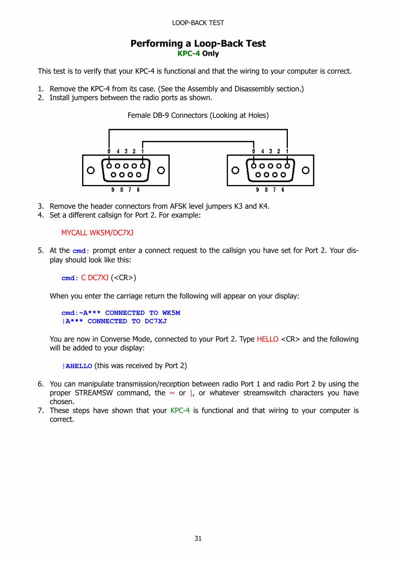
1. Remove the KPC-4 from its case. (See the Assembly and Disassembly section.)2. Install jumpers between the radio ports as shown.
Female DB-9 Connectors (Looking at Holes)
3. Remove the header connectors from AFSK level jumpers K3 and K4.4. Set a different callsign for Port 2. For example:
MYCALL WK5M/DC7XJ
5. At the cmd: prompt enter a connect request to the callsign you have set for Port 2. Your dis-
play should look like this:
cmd: C DC7XJ (<CR>)
When you enter the carriage return the following will appear on your display:
cmd:~A*** CONNECTED TO WK5M
|A*** CONNECTED TO DC7XJ
You are now in Converse Mode, connected to your Port 2. Type HELLO <CR> and the followingwill be added to your display:
|AHELLO (this was received by Port 2)
6. You can manipulate transmission/reception between radio Port 1 and radio Port 2 by using theproper STREAMSW command, the ~ or |, or whatever streamswitch characters you havechosen.
7. These steps have shown that your KPC-4 is functional and that wiring to your computer iscorrect.

MODEM DISCONNECT
32
Modem DisconnectKAM and KPC-4 only
Headers are appropriately labeled on the PC board. Refer to the parts location diagram for help onlocating them. Also refer to the Assembly and Disassembly section for information on obtaining ac-cess to the interior of the TNC.
Headers K8 and K9
These connectors are provided for use with an external modem such as the KM-2400 modem(QPSK) or the MSK modem.

SWDETLED MODIFICATION
33
SWDETLED ModificationKPC-1 Only
To perform the Software Carrier Detect LED (SWDETLED) enable modification, remove the circuitboard from the case as detailed in the Assembly and Disassembly section. Next, remove the 7910(U-11) and bend pin25 out slightly so that it will not make contact with the socket when the IC isre-inserted in U-11. Re-install the 7910 in socket U-11. With this modification completed, you willnot detect ANY packets unless CD is set to SOFTWARE.

SAMPLE TERMINAL PROGRAMS
34
Sample Terminal Programs
The following BASIC programs can be used to operate the Kantronics TNCs with the computerslisted.
CAUTION: Each of the programs is a simple example of the necessary statements required to con-figure the computer for operation with an external device via the RS-232/TTL port. These simpleterminal programs will NOT do file transfer or buffering of data and typing.
BASIC terminal program for the VIC-20/C-64
10 CLOSE220 OPEN2,2,3,CHR$(6)30 GET#2,A$40 REM50 GET B$55 IF B$=CHR$(133) THEN GOTO 10060 IF B$<>""THEN PRINT#2,B$;70 GET#2,C$80 PRINT C$;90 GOTO 50100 CLOSE2110 END
The #1 function key will return the C-64 computer to BASIC. If graphics characters appear, use theshift key with the Commodore key to change the character set. For use with the VIC-20, changethe TNC COMMAND parameter to $05 (see Commands section of Commands Manual). The a Ctrl-2typed on the VIC-20 will return the TNC to the Command Mode. (The VIC-20 does not have a Ctrl-C command.)
This program uses a 3-wire cable as described in the Connecting Your Computer section. Wire onlyRXD, TXD and SG.
Basic terminal program for the TRS-80 Model III
1 OUT232,02 OUT232,1643 OUT233,854 CLS10 IF INP(234) AND 128 THEN PRINT CHR$(INP(235));:GOTO 1020 A$=INKEY$:IF A$="" THEN 1030 IF INP(234)AND 64 THEN OUT 235,ASC(A$): GOTO 10 ELSE GOTO 30
Put the TRS-80 Model III in BASIC. Type and run the program. When the program is run, thescreen will go blank. At this time turn on the TNC. The TNC will send thePRESS * FOR AUTOBAUD routine.
This program uses a 3-wire cable as described in the Connecting Your Computer section. Wire onlyRXD, TXD and SG.

SAMPLE TERMINAL PROGRAMS
35
BASIC terminal program for the Apple computer with the Super Serial Card
10 REM THIS PROGRAM SETS UP THE SSC FOR THE TNC20 REM ASSUMES THE SSC IS IN SLOT #230 A$=CHR$(1):D$=CHR$(4)40 PRINT D$;"PR#2"50 PRINT A$;"6 BAUD": REM SET 300 BAUD60 PRINT A$;"0 PARITY":REM NO PARITY70 PRINT A$;"SD":REM DISABLE SPECIAL CHARS & ENABLE ESC KEY80 PRINT A$;TERM MODE"90 REM IN TERMINAL MODE-TALK TO TNC100 REM PRESS<CTRL RESET>TO EXIT PROGRAM110 PRINT A$;"RESET"120 END
BASIC terminal program for the Zenith Z-100
10 KEY OFF: CLS: CLOSE20 OPEN"COM1:300,8,N,1" AS #130 OPEN"SCRN:"FOR OUTPUT AS #240 A$=INKEY$:IF A$=""THEN 6050 PRINT #1,A$60 IF LOC(1)=0 THEN 4070 B$=INPUT$(lOC(1),#1)80 PRINT #2,B$90 GOTO 40
BASIC terminal program for the Atari 850 Interface
10 GOSUB 160020 FOR LOOP=0 TO 1 STEP 050 IF PEEK(764)=255 THEN 8060 GET #KEY,A:IF A=125 THEN A=870 PUT #1,A80 STATUS #1,A:BUF=PEEK(747)90 IF BUF=0 THEN NEXT LOOP100 FOR I01 TO BUF110 GET #1,A:IF A=8 THEN A=126120 ?CHR$(A);:NEXT I140 NEXT LOOP1600 KEY=41610 XIO 36,#1,8,0,"R1:":REM-300 BAUD1630 XIO 34,#1,48,0,"R1:"1640 OPEN #1,13,0,"R1:"1650 XIO 40,#1,0,0,"R1:"1655 OPEN #KEY,4,0,"K:"1660 RETURN
This program uses a 5-wire cable as described in the Connecting Your Computer section. When us-ing this program, set the TNC's DELETE and AUTOLF commands to OFF.

SPECIFICATIONS
36
SpecificationsKAM, KPC-4, KPC-2, KPC-2400, KPC-1
Size: KAM: 1-¾" × 6" × 9"KPC-4, KPC-2, KPC-2400, KPC-1: 1-¾" × 6" × 8"
Weight: KAM: 2-½ lbs.KPC-4, KPC-2, KPC-2400, KPC-1: 2-¼ lbs.
Power Requirements: KAM: 11 VDC to 14 VDC, < 300 mAKPC-4: 11 VDC to 14 VDC, < 200 mAKPC-2: 9 VDC to 14 VDC, < 250 mAKPC-2400: 10 VDC to 15 VDC, < 330 mAKPC-1: 10 VDC to 14 VDC, < 330 mA
Power Plug Polarity: All units: Center pin positive
Watch Dog Timer: KAM, KPC-4, KPC-2400: 2 – ½ minutes(Optional board for other units)
External Carrier Detect (XCD): KAM, KPC-4: Pulldown to ground
External Reset: KPC-4: Pulldown to ground
PTT Output: All units: Open Collector, +40 VDC max.
FSK Output: KAM HF: Open collector, +40 VDC max.
Key Output: KAM HF: Reed relay contact rated 0.5 A and 300 VDC max.(100 Ω series resistor)
Audio Output: KAM HF All Others
Output drive: 100 mVpp (LO) 10 mVpp (LO)500 mVpp (HI) 50 mVpp (HI)1.6 Vpp (no jump) 1.7 Vpp (no jump) (does not apply to KPC-1)
Output Impedance: 600 Ω 600 Ω (AC coupled) (AC coupled)
Audio Input: KAM HF All Others
Input Sensitivity: 20 mVpp (FM) 20 mVpp100 mVpp (AM)
Dynamic Range: >60 dB >60 dB Input Impedance: 600 Ω 600 Ω (unbalanced) Max. Input Voltage: ±12 VDC ±12 VDC
Modes of Operation: KAM: Packet, CW, RTTY, ASCII, AMTOR (CCIR 476 and CCIR625), WEFAX, KISS, NAVTEX/AMTEX, Host
All Others: Packet, WEFAX, Kiss, Host
Other Features: All units: PBBS, KA-NODEKAM, KPC-4: Dual port with gateway and cross-connect
37
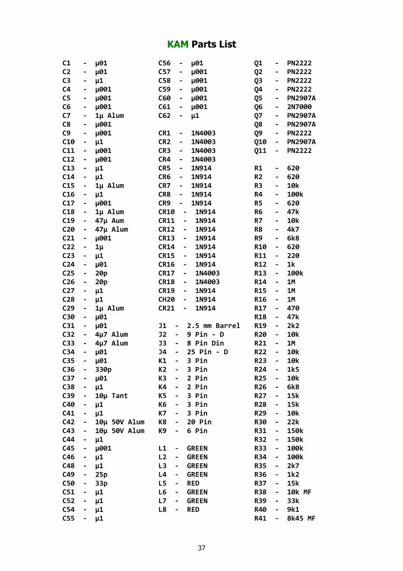
KAM Parts List
C1 - µ01 C56 - µ01 Q1 - PN2222C2 - µ01 C57 - µ001 Q2 - PN2222C3 - µ1 C58 - µ001 Q3 - PN2222C4 - µ001 C59 - µ001 Q4 - PN2222C5 - µ001 C60 - µ001 Q5 - PN2907AC6 - µ001 C61 - µ001 Q6 - 2N7000C7 - 1µ Alum C62 - µ1 Q7 - PN2907AC8 - µ001 Q8 - PN2907AC9 - µ001 CR1 - 1N4003 Q9 - PN2222C10 - µ1 CR2 - 1N4003 Q10 - PN2907AC11 - µ001 CR3 - 1N4003 Q11 - PN2222C12 - µ001 CR4 - 1N4003C13 - µ1 CR5 - 1N914 R1 - 620C14 - µ1 CR6 - 1N914 R2 - 620C15 - 1µ Alum CR7 - 1N914 R3 - 10kC16 - µ1 CR8 - 1N914 R4 - 100kC17 - µ001 CR9 - 1N914 R5 - 620C18 - 1µ Alum CR10 - 1N914 R6 - 47kC19 - 47µ Aum CR11 - 1N914 R7 - 10kC20 - 47µ Alum CR12 - 1N914 R8 - 4k7C21 - µ001 CR13 - 1N914 R9 - 6k8C22 - 1µ CR14 - 1N914 R10 - 620C23 - µ1 CR15 - 1N914 R11 - 220C24 - µ01 CR16 - 1N914 R12 - 1kC25 - 20p CR17 - 1N4003 R13 - 100kC26 - 20p CR18 - 1N4003 R14 - 1MC27 - µ1 CR19 - 1N914 R15 - 1MC28 - µ1 CH20 - 1N914 R16 - 1MC29 - 1µ Alum CR21 - 1N914 R17 - 470C30 - µ01 R18 - 47kC31 - µ01 J1 - 2.5 mm Barrel R19 - 2k2C32 - 4µ7 Alum J2 - 9 Pin - D R20 - 10kC33 - 4µ7 Alum J3 - 8 Pin Din R21 - 1MC34 - µ01 J4 - 25 Pin - D R22 - 10kC35 - µ01 K1 - 3 Pin R23 - 10kC36 - 330p K2 - 3 Pin R24 - 1k5C37 - µ01 K3 - 2 Pin R25 - 10kC38 - µ1 K4 - 2 Pin R26 - 6k8C39 - 10µ Tant K5 - 3 Pin R27 - 15kC40 - µ1 K6 - 3 Pin R28 - 15kC41 - µ1 K7 - 3 Pin R29 - 10kC42 - 10µ 50V Alum K8 - 20 Pin R30 - 22kC43 - 10µ 50V Alum K9 - 6 Pin R31 - 150kC44 - µ1 R32 - 150kC45 - µ001 L1 - GREEN R33 - 100kC46 - µ1 L2 - GREEN R34 - 100kC48 - µ1 L3 - GREEN R35 - 2k7C49 - 25p L4 - GREEN R36 - 1k2C50 - 33p L5 - RED R37 - 15kC51 - µ1 L6 - GREEN R38 - 10k MFC52 - µ1 L7 - GREEN R39 - 33kC54 - µ1 L8 - RED R40 - 9k1C55 - µ1 R41 - 8k45 MF

38
R42 - 2k7 R98 - 100k RN1 - 10kR43 - 22k R99 - 33k RN2 - 10kR44 - 10k R100 - 1k RN3 - 10kR45 - 680k R101 - 1k RN4 - 10kR46 - 620k R102 - 10k RN5 - 10kR47 - 220k R103 - 100k RN6 - 220kR48 - 10k R104 - 51k RN7 - 100kR49 - 5k1 R105 - 10k RN8 - 10kR50 - 15k R106 - 6k8R51 - 9k53 MF R107 - 100R52 - 82k R108 - 100kR53 - 220k R109 - 120kR54 - 100k R110 - 270R55 - 150k R111 - 270R56 - 150k R112 - 6k8R57 - 150k R113 - 270R58 - 33kR59 - 33k RFC1 - 10µHR60 - 2k7R61 - 1k2 S1 - PUSH PUSHR62 - 15k S2 - PUSH PUSHR63 - 5k1R64 - 82k U1 - MC34074R65 - 9k53 MF U2 - 741IC04R66 - 68k U3 - 4018R67 - 47k U4 - MF4CNR68 - 100k U5 - TCM3105R69 - 150k U6 - MF10CNR70 - 22k U7 - LM339R71 - 68k U8 - MF10CNR72 - 100k U9 - MF10CNR73 - 100k U10 - MF4CNR74 - 1M U11 - LM324R75 - 220 U12 - MF10CNR76 - 180k U13 - LM358R77 - 100k U14 - 4066R78 - 100k U15 - 4069R79 - 100k U16 - LM3914R80 - 2k2 U17 - 74HC259R81 - 22k U18 - 74HC10R82 - 2k2 U19 - 74HC04R83 - 100k U20 - SPARER84 - 9k1 U21 - 42832R85 - 100k U22 - 27C256R86 - 2k2 U23 - 71054R87 - 220 U24 - SPARER88 - 220 U25 - X2404R90 - 620 U26 - 63B03XR91 - 1M U27 - 4070R92 - 2k2 U28 - MC34074R93 - 1k U29 - LM358R94 - 2k2 U30 - LM339R95 - 10kR96 - 100k VR1 - 78M05 +5V RegR97 - 6k8 VR2 - 79L05 -5V Reg

39
KAM COMPONENT PLACEMENT DIAGRAM

40
KAM SCHEMATIC

41

42
KPC-4 Parts List
C1 - µ1 C54 - µ001 R27 - 220C2 - 20p C55 – µ001 R28 - 1MC3 - 20p C56 - µ001 R29 - 1kC4 - µ001 C57 - µ1 R30 - 33kC5 - µ001 R31 - 33kC6 - µ001 CR1 - 1N914 R32 - 8k45C7 - µ01 CR2 - 1N914 R33 - 10kC8 - µ001 CR3 - 1N914 R34 - 10kC9 - µ01 CR4 - 1N914C10 - µ1 CR5 - 1N914 R39 - 9k1C11 - µ001 CR6 - 1N914 R40 - 33kC12 - µ001 CR7 - 1N914 R41 - 2k2C13 - 1µ CR8 - 1N4001 R42 - 1MC14 - 1µ CR9 - 1N4001 R43 - 1MC15 - µ001 CR10 - 1N4001 R44 - 1MC16 - µ001 CR11 - 1N4001 R45 - 10kC17 - µ1 CR12 - 1N4001 R46 - 100kC18 - µ1 CR13 - 1N914 R47 - 1kC19 - µ1 R48 - 1kC20 - µ001 Q1 - PN2222 R49 - 100kC21 - µ001 Q2 - PN2222 R50 - 10kC22 - µ1 Q3 - PN2222 R51 - 220C23 - µ1 Q4 - PN2222 R52 - 2k2C24 - µ1 Q5 - PN2907 R53 - 2k2C25 - µ1 Q6 - 2N2222 R54 - 100k
R55 - 22kC28 - 47µ R1 - 100k R56 - 220C29 - 47µ R2 - 100k R57 - 220C30 - µ1 R3 - 10k R58 - 220C31 - 20p R4 - 620 R59 - 100kC32 - 20p R5 - 620 R60 - 2k2C33 - µ1 R6 - 100k R61 - 100kC34 - µ1 R7 - 10k R62 - 10kC35 - 10µ Tant R8 - 10k R63 - 6k8C36 - µ1 R9 - 100k R64 - 51kC37 - µ1 R10 - 47k R65 - 100kC38 - 4.1 R11 - 4k7 R66 - 120kC39 - µ1 R12 - 4k7 R67 - 6k8C40 - 10 R13 - 47k R68 - 270C41 - 10 R14 - 620 R69 - 270C42 - µ1 R15 - 10k R70 - 6k8C43 - µ001 R16 - 10k R71 - 270C44 - µ1 R17 - 620C45 - µ1 R18 - 15k RFC1 - 10µHC46 - µ1 R19 - 6k8C47 - µ1 R20 - 6k8 S1P1 - 220C48 - µ1 R21 - 15k S1P2 - 100kC49 - µ1 R22 - 6k8 S1P3 - 10kC50 - µ01 R23 - 1kC51 - µ001 R24 - 1M U1 - MC34074C52 - µ001 R25 - 220 U2 - 3105C53 - µ001 R26 - 6k8 U3 - 3105

43
KPC-4 COMPONENT PLACEMENT DIAGRAM

44
KPC-4 SCHEMATIC

45
KPC-2 Parts List
C1 - µ1 J1 - power jack R25 - 6k8C2 - 10µ Tant J2 - 9-pin D-connector R26 - 6k8C3 - µ001 Disc J3 - 3.5 audio jack R27 - 120kC4 - 4µ7 Alum J4 - 25-pin D-connector R29 - 100kC5 - µ1 MLC R30 - 51kC6 - µ1 MLC K1 - 3 pin header R31 - 120kC7 - µ1 MLC K2 - 3 pin header R32 - 10kC8 - µ1 MLC K3 - 3 pin header R33 - 10kC9 - µ1 MLC R34 - 10kC10 - µ002 Disc L-1 - Red LED R35 - 100kC11 - 20p L-2 - Red LED R36 - 10kC13 - µ1 MLC L-3 - Red LED R37 - 2k2C14 - µ1 MLC L-4 - Red LED R38 - 100kC15 - µ01 Disc L-5 - Green LED R39 - 4k7C16 - µ01 Disc R40 - 220C17 - µ001 MLC N1 J5 R41 - 220C18 - µ01 Disc Q1 M1 jumper R42 - 220C19 - µ1 ML hole 9-10 R43 - 220C20 - µ01 Disc R44 - 220C21 - µ001 Disc Q1 - PN2907AC22 - µ001 Disc Q2 - PN2222 RFC1 - 10µHC23 - 1µ Alu Q3 - PN2222 S1 - push push swC24 - µ01 DiscC25 - µ001 Dis R1 - 100k S1P1 - 10kC26 - µ001 Dis R2 - 120k S1P2 - 100kC27 - µ001 Dis R3 - 100kC28 - µ001 Dis R4 - 4k7 U1 - 7910 28 pinC29 - µ001 Dis R5 - 22k U2 - LM358C30 - µ001 Dis R6 - 4k7 U3 - LM358C31 - 20p R7 - 1M U4 - MC34074C32 - 20p R8 - 100 U5 - 74HC14C34 - µ1 MLC R9 - 100k U6 - 4070C35 - µ1 MLC R10 - 33k U7 - 4070C36 - µ1 MLC R11 - 100k U8 - 63B03X socketC37 - µ1 MLC R12 - 100 U9 - 27256 socketC38 - µ1 MLC R13 - 1M U11 - 62256 socketC39 - µ1 MLC R14 - 470 U12 - 2404 socket
R15 - 100k U14 - 74HC04CR1 - 1N914 R16 - 3k3 U15 - 4069CR2 - 1N4003 R17 - 4k7CR3 - 1N4003 R18 - 620 VR1 - 78M05CR4 - 1N4003 R19 - 620 VR2 - 79L05CR5 - 1N914 R20 - 10kCR6 - 1N914 R21 - 270 XTAL1 - 2.4576 MHzCR7 - 1N914 R22 - 270 XTAL2 - 7.3728 MHzCR8 - 1N914 R23 - 270CR9 - 1N4003 R24 - 6k8CR10 - 1N914

46
KPC-2 COMPONENT PLACEMENT DIAGRAM

47
KPC-2 SCHEMATIC
48
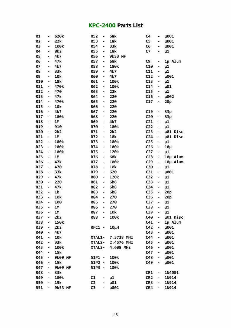
KPC-2400 Parts List
R1 - 620k R52 - 68k C4 - µ001R2 - 22k R53 - 18k C5 - µ001R3 - 100k R54 - 33k C6 - µ001R4 - 8k2 R55 - 18k C7 - µ1R5 - 4k7 R56 - 9k53 MFR6 - 47k R57 - 68k C9 - 1µ AlumR7 - 4k7 R58 - 180k C10 - µ1R8 - 33k R59 - 4k7 C11 - µ1R9 - 10k R60 - 4k7 C12 - µ001R10 - 18k R61 - 100k C13 - µ1R11 - 470k R62 - 100k C14 - µ01R12 - 470 R63 - 22k C15 - µ1R13 - 47k R64 - 220 C16 - µ002R14 - 470k R65 - 220 C17 - 20pR15 - 10k R66 - 220R16 - 4k7 R67 - 220 C19 - 33pR17 - 100k R68 - 220 C20 - 33pR18 - 1M R69 - 4k7 C21 - µ1R19 - 910 R70 - 100k C22 - µ1R20 - 2k2 R71 - 2k2 C23 - µ01 DiscR21 - 1M R72 - 10k C24 - µ01 DiscR22 - 100k R73 - 100k C25 - µ1R23 - 100k R74 - 100k C26 - 10µR24 - 100k R75 - 120k C27 - µ1R25 - 1M R76 - 68k C28 - 10µ AlumR26 - 47k R77 - 100k C29 - 10µ AlumR27 - 470 R78 - 10k C30 - µ1R28 - 33k R79 - 620 C31 - µ001R29 - 47k R80 - 120k C32 - µ1R30 - 220 R81 - 6k8 C33 - µ1R31 - 47k R82 - 6k8 C34 - µ1R32 - 1k R83 - 6k8 C35 - 20pR33 - 10k R84 - 270 C36 - 20pR34 - 100 R85 - 270 C37 - µ1R35 - 1M R86 - 270 C38 - µ1R36 - 1M R87 - 10k C39 - µ1R37 - 2k2 R88 - 100k C40 - µ01 DiscR38 - 150k C41 - 1µ AlumR39 - 2k2 RFC1 - 10µH C42 - µ001R40 - 4k7 C43 - µ001R41 - 10k XTAL1- 7.3728 MHz C44 - µ001R42 - 33k XTAL2- 2.4576 MHz C45 - µ001R43 - 100k XTAL3- 4.608 MHz C46 - µ001R44 - 15k C47 - µ001R45 - 9k09 MF S1P1 - 100k C48 - µ001R46 - 15k S1P2 - 100k C49 - µ001R47 - 9k09 MF S1P3 - 100kR48 - 33k CR1 - 1N4001R49 - 100k C1 - µ1 CR2 - 1N914R50 - 15k C2 - µ01 CR3 - 1N914R51 - 9k53 MF C3 - µ001 CR4 - 1N914

49
KPC-2400 COMPONENT PLACEMENT DIAGRAM

50
KPC-2400 SCHEMATIC

51
PACTOR Option AddendumKAM EPROM Version 6.1
Thank you for purchasing the PACTOR Option for your KAM. We believe you'll find many hours ofenjoyment and many new friends as you explore this new digital mode.
The enclosed EPROM for your KAM contains some minor changes since the original release, ver-sion 6.0. The manual indicates (on pages 3 and 10) that you must use the PTLISTEN mode tomonitor PACTOR transmissions. By popular demand, this has been changed in version 6.1 to allowmonitoring in Standby Mode too.
To monitor PACTOR in Standby Mode, set the MONITOR command to ON/XXX and the ARQBBScommand to OFF. In PACTOR Standby Mode, you can also transmit FEC by typing Ctrl-C T and re-turn to receive by typing Ctrl-C E.
We've also added the NAVLOG command, an immediate command, to display a list of NAVTEXmessages that have been properly received in the NAVTEX Mode.