Embed Size (px)
Citation preview
KeeGuard Topfix Operation & Maintenance Manual
KeeGuardTopfix
S A F E T Y A T T H E H I G H E S T L E V E L
2
3
KeeGuardTopfix
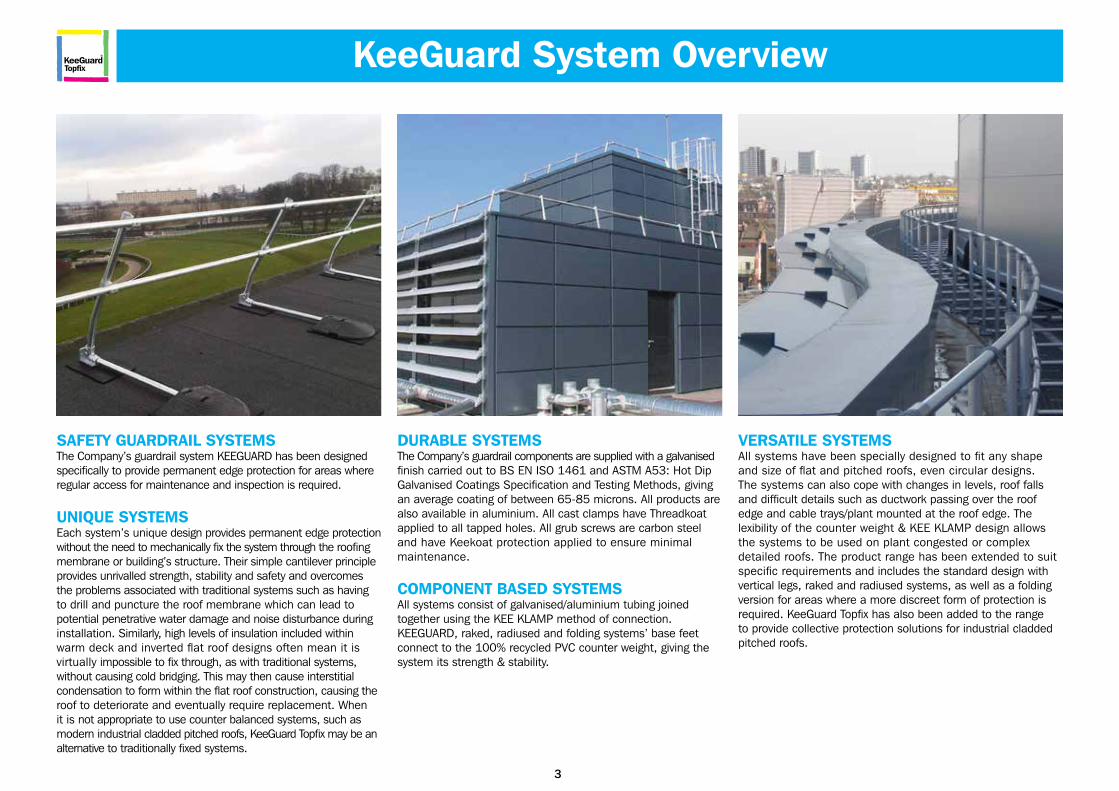
SAFETY GUARDRAIL SYSTEMS The Company’s guardrail system KEEGUARD has been designed specifically to provide permanent edge protection for areas where regular access for maintenance and inspection is required.
UNIQUE SYSTEMS Each system’s unique design provides permanent edge protection without the need to mechanically fix the system through the roofing membrane or building’s structure. Their simple cantilever principle provides unrivalled strength, stability and safety and overcomes the problems associated with traditional systems such as having to drill and puncture the roof membrane which can lead to potential penetrative water damage and noise disturbance during installation. Similarly, high levels of insulation included within warm deck and inverted flat roof designs often mean it is virtually impossible to fix through, as with traditional systems, without causing cold bridging. This may then cause interstitial condensation to form within the flat roof construction, causing the roof to deteriorate and eventually require replacement. When it is not appropriate to use counter balanced systems, such as modern industrial cladded pitched roofs, KeeGuard Topfix may be an alternative to traditionally fixed systems.
DURABLE SYSTEMS The Company’s guardrail components are supplied with a galvanised finish carried out to BS EN ISO 1461 and ASTM A53: Hot Dip Galvanised Coatings Specification and Testing Methods, giving an average coating of between 65-85 microns. All products are also available in aluminium. All cast clamps have Threadkoat applied to all tapped holes. All grub screws are carbon steel and have Keekoat protection applied to ensure minimal maintenance.
COMPONENT BASED SYSTEMS All systems consist of galvanised/aluminium tubing joinedtogether using the KEE KLAMP method of connection.KEEGUARD, raked, radiused and folding systems’ base feet connect to the 100% recycled PVC counter weight, giving the system its strength & stability.
VERSATILE SYSTEMS All systems have been specially designed to fit any shape and size of flat and pitched roofs, even circular designs.The systems can also cope with changes in levels, roof falls and difficult details such as ductwork passing over the roof edge and cable trays/plant mounted at the roof edge. The lexibility of the counter weight & KEE KLAMP design allows the systems to be used on plant congested or complex detailed roofs. The product range has been extended to suit specific requirements and includes the standard design with vertical legs, raked and radiused systems, as well as a folding version for areas where a more discreet form of protection is required. KeeGuard Topfix has also been added to the range to provide collective protection solutions for industrial cladded pitched roofs.
KeeGuard System Overview
4
KeeGuardTopfix
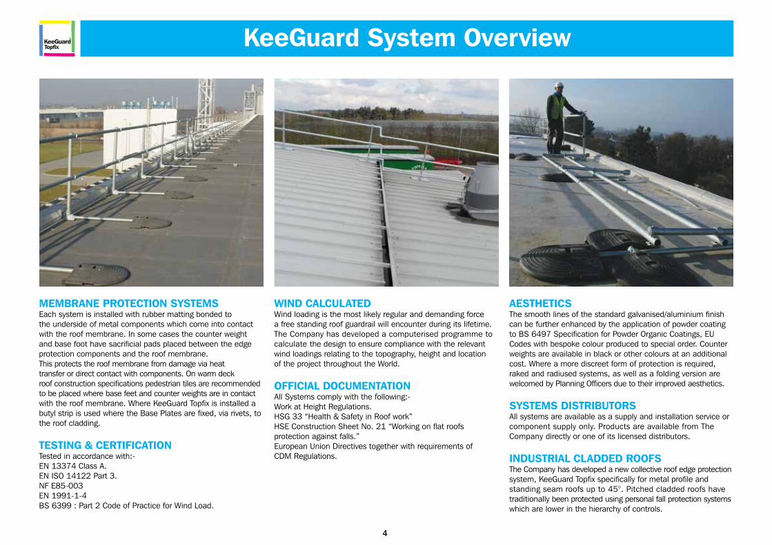
MEMBRANE PROTECTION SYSTEMS Each system is installed with rubber matting bonded to the underside of metal components which come into contact with the roof membrane. In some cases the counter weight and base foot have sacrificial pads placed between the edge protection components and the roof membrane. This protects the roof membrane from damage via heat transfer or direct contact with components. On warm deck roof construction specifications pedestrian tiles are recommended to be placed where base feet and counter weights are in contact with the roof membrane. Where KeeGuard Topfix is installed a butyl strip is used where the Base Plates are fixed, via rivets, to the roof cladding.
TESTING & CERTIFICATION Tested in accordance with:- EN 13374 Class A. EN ISO 14122 Part 3. NF E85-003 EN 1991-1-4 BS 6399 : Part 2 Code of Practice for Wind Load.
WIND CALCULATED Wind loading is the most likely regular and demanding forcea free standing roof guardrail will encounter during its lifetime. The Company has developed a computerised programme to calculate the design to ensure compliance with the relevant wind loadings relating to the topography, height and locationof the project throughout the World.
OFFICIAL DOCUMENTATION All Systems comply with the following:- Work at Height Regulations. HSG 33 “Health & Safety in Roof work” HSE Construction Sheet No. 21 “Working on flat roofsprotection against falls.” European Union Directives together with requirements of CDM Regulations.
AESTHETICS The smooth lines of the standard galvanised/aluminium finish can be further enhanced by the application of powder coating to BS 6497 Specification for Powder Organic Coatings, EU Codes with bespoke colour produced to special order. Counter weights are available in black or other colours at an additional cost. Where a more discreet form of protection is required, raked and radiused systems, as well as a folding version are welcomed by Planning Officers due to their improved aesthetics.
SYSTEMS DISTRIBUTORS All systems are available as a supply and installation service or component supply only. Products are available from The Company directly or one of its licensed distributors.
INDUSTRIAL CLADDED ROOFS The Company has developed a new collective roof edge protection system, KeeGuard Topfix specifically for metal profile and standing seam roofs up to 45°. Pitched cladded roofs havetraditionally been protected using personal fall protection systems which are lower in the hierarchy of controls.
KeeGuard System Overview
5
KeeGuardTopfix
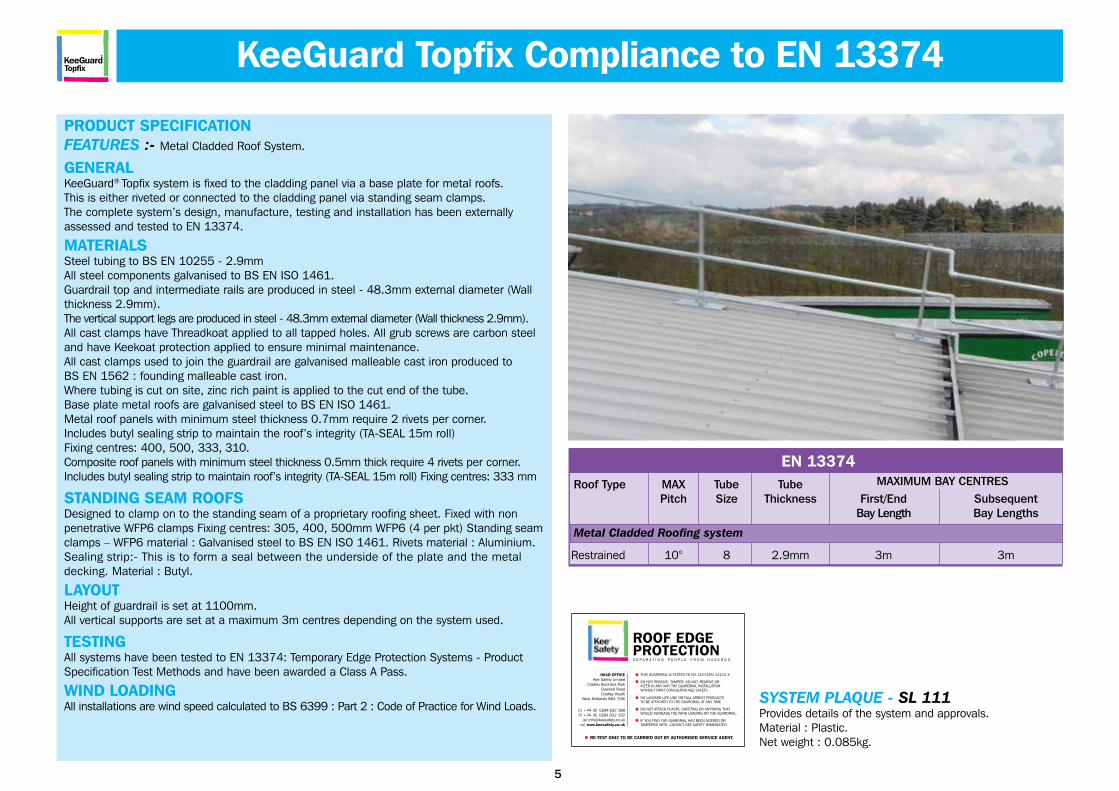
EN 13374Roof Type MAX Tube Tube Pitch Size Thickness First/End Subsequent Bay Length Bay Lengths
Metal Cladded Roofing system
Restrained 10° 8 2.9mm 3m 3m
SYSTEM PLAQUE - SL 111Provides details of the system and approvals.Material : Plastic.Net weight : 0.085kg.
PRODUCT SPECIFICATIONFEATURES :- Metal Cladded Roof System.
GENERALKeeGuard® Topfix system is fixed to the cladding panel via a base plate for metal roofs.This is either riveted or connected to the cladding panel via standing seam clamps.The complete system’s design, manufacture, testing and installation has been externallyassessed and tested to EN 13374.
MATERIALSSteel tubing to BS EN 10255 - 2.9mm All steel components galvanised to BS EN ISO 1461.Guardrail top and intermediate rails are produced in steel - 48.3mm external diameter (Wall thickness 2.9mm).The vertical support legs are produced in steel - 48.3mm external diameter (Wall thickness 2.9mm).All cast clamps have Threadkoat applied to all tapped holes. All grub screws are carbon steel and have Keekoat protection applied to ensure minimal maintenance. All cast clamps used to join the guardrail are galvanised malleable cast iron produced toBS EN 1562 : founding malleable cast iron.Where tubing is cut on site, zinc rich paint is applied to the cut end of the tube.Base plate metal roofs are galvanised steel to BS EN ISO 1461.Metal roof panels with minimum steel thickness 0.7mm require 2 rivets per corner.Includes butyl sealing strip to maintain the roof’s integrity (TA-SEAL 15m roll)Fixing centres: 400, 500, 333, 310.Composite roof panels with minimum steel thickness 0.5mm thick require 4 rivets per corner. Includes butyl sealing strip to maintain roof’s integrity (TA-SEAL 15m roll) Fixing centres: 333 mm
STANDING SEAM ROOFS Designed to clamp on to the standing seam of a proprietary roofing sheet. Fixed with non penetrative WFP6 clamps Fixing centres: 305, 400, 500mm WFP6 (4 per pkt) Standing seam clamps – WFP6 material : Galvanised steel to BS EN ISO 1461. Rivets material : Aluminium. Sealing strip:- This is to form a seal between the underside of the plate and the metal decking. Material : Butyl.
LAYOUTHeight of guardrail is set at 1100mm.All vertical supports are set at a maximum 3m centres depending on the system used.
TESTINGAll systems have been tested to EN 13374: Temporary Edge Protection Systems - Product Specification Test Methods and have been awarded a Class A Pass.
WIND LOADINGAll installations are wind speed calculated to BS 6399 : Part 2 : Code of Practice for Wind Loads.
MAXIMUM BAY CENTRES
KeeGuard Topfix Compliance to EN 13374
ROOF EDGEPROTECTION
THIS GUARDRAIL IS TESTED TO EN 13374/EN 14122-3
DO NOT REMOVE, TAMPER, ADJUST, REMOVE ORALTER IN ANY WAY THE GUARDRAIL INSTALLATIONWITHOUT FIRST CONSULTING KEE SAFETY.
NO LANYARD LIFE LINE OR FALL ARREST PRODUCTSTO BE ATTACHED TO THE GUARDRAIL AT ANY TIME
DO NOT ATTACH PLASTIC SHEETING OR ANYTHING THAT WOULD INCREASE THE WIND LOADING ON THE GUARDRAIL.
IF YOU FIND THE GUARDRAIL HAS BEEN ALTERED ORTAMPERED WITH, CONTACT KEE SAFETY IMMEDIATELY
RE-TEST ONLY TO BE CARRIED OUT BY AUTHORISED SERVICE AGENT.
HEAD OFFICEKee Safety Limited
Cradley Business ParkOverend RoadCradley Heath
West Midlands B64 7DW
(t) +44 (0) 1384 632 188(f) +44 (0) 1384 632 192
(e) [email protected](w) www.keesafety.co.uk
S E P A R A T I N G P E O P L E F R O M H A Z A R D S
6
KeeGuardTopfix
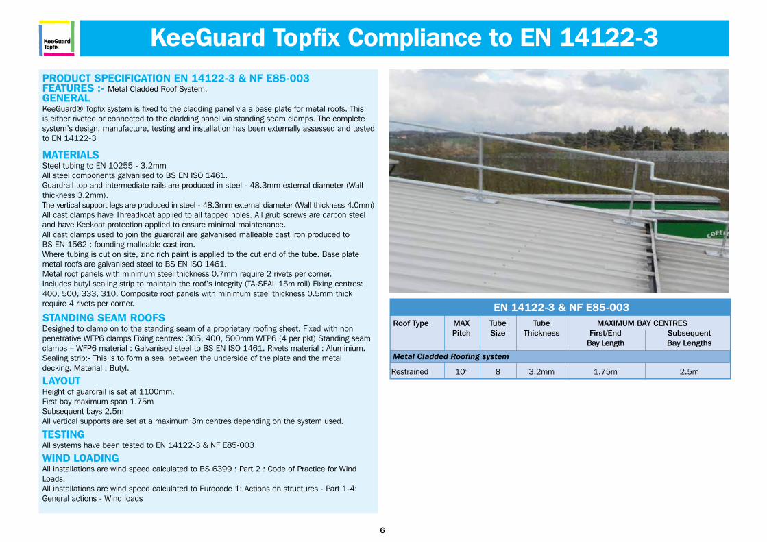
PRODUCT SPECIFICATION EN 14122-3 & NF E85-003FEATURES :- Metal Cladded Roof System.GENERALKeeGuard® Topfix system is fixed to the cladding panel via a base plate for metal roofs. Thisis either riveted or connected to the cladding panel via standing seam clamps. The completesystem’s design, manufacture, testing and installation has been externally assessed and tested to EN 14122-3
MATERIALSSteel tubing to EN 10255 - 3.2mm All steel components galvanised to BS EN ISO 1461.Guardrail top and intermediate rails are produced in steel - 48.3mm external diameter (Wall thickness 3.2mm).The vertical support legs are produced in steel - 48.3mm external diameter (Wall thickness 4.0mm)All cast clamps have Threadkoat applied to all tapped holes. All grub screws are carbon steel and have Keekoat protection applied to ensure minimal maintenance. All cast clamps used to join the guardrail are galvanised malleable cast iron produced toBS EN 1562 : founding malleable cast iron.Where tubing is cut on site, zinc rich paint is applied to the cut end of the tube. Base plate metal roofs are galvanised steel to BS EN ISO 1461.Metal roof panels with minimum steel thickness 0.7mm require 2 rivets per corner.Includes butyl sealing strip to maintain the roof’s integrity (TA-SEAL 15m roll) Fixing centres: 400, 500, 333, 310. Composite roof panels with minimum steel thickness 0.5mm thickrequire 4 rivets per corner.
STANDING SEAM ROOFSDesigned to clamp on to the standing seam of a proprietary roofing sheet. Fixed with nonpenetrative WFP6 clamps Fixing centres: 305, 400, 500mm WFP6 (4 per pkt) Standing seamclamps – WFP6 material : Galvanised steel to BS EN ISO 1461. Rivets material : Aluminium.Sealing strip:- This is to form a seal between the underside of the plate and the metaldecking. Material : Butyl.
LAYOUTHeight of guardrail is set at 1100mm.First bay maximum span 1.75mSubsequent bays 2.5mAll vertical supports are set at a maximum 3m centres depending on the system used.
TESTINGAll systems have been tested to EN 14122-3 & NF E85-003
WIND LOADINGAll installations are wind speed calculated to BS 6399 : Part 2 : Code of Practice for WindLoads. All installations are wind speed calculated to Eurocode 1: Actions on structures - Part 1-4:General actions - Wind loads
EN 14122-3 & NF E85-003Roof Type MAX Tube Tube MAXIMUM BAY CENTRES Pitch Size Thickness First/End Subsequent Bay Length Bay Lengths
Metal Cladded Roofing system
Restrained 10° 8 3.2mm 1.75m 2.5m
KeeGuard Topfix Compliance to EN 14122-3
8
KeeGuardTopfix
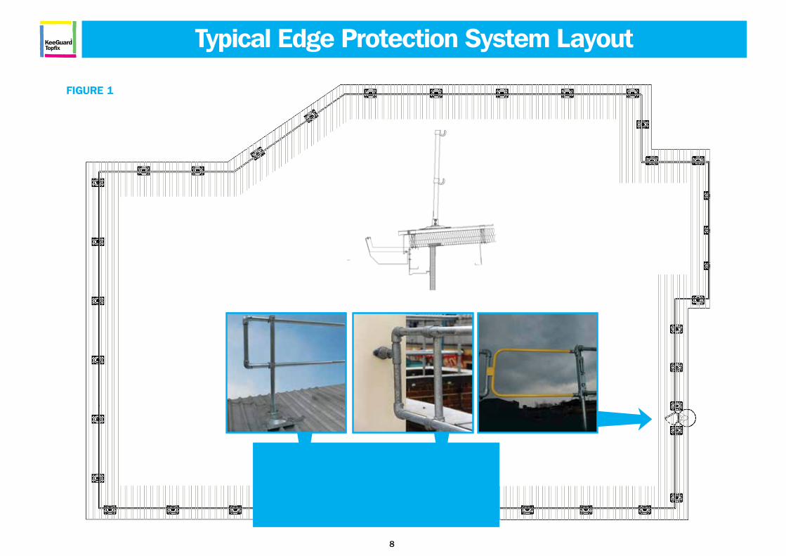
FIGURE 1
NOTE: End DetailRefer to Product
SpecificationStandard!
Typical Edge Protection System Layout
9
KeeGuardTopfix
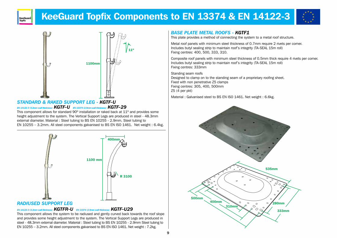
BASE PLATE METAL ROOFS - KGTF1This plate provides a method of connecting the system to a metal roof structure.
Metal roof panels with minimum steel thickness of 0.7mm require 2 rivets per corner.Includes butyl sealing strip to maintain roof’s integrity (TA-SEAL 15m roll)Fixing centres: 400, 500, 333, 310.
Composite roof panels with minimum steel thickness of 0.5mm thick require 4 rivets per corner. Includes butyl sealing strip to maintain roof’s integrity (TA-SEAL 15m roll)Fixing centres: 333mm
Standing seam roofs Designed to clamp on to the standing seam of a proprietary roofing sheet.Fixed with non penetrative Z5 clampsFixing centres: 305, 400, 500mmZ5 (4 per pkt)
Material : Galvanised steel to BS EN ISO 1461. Net weight : 6.6kg.
280mm
535mm
500mm400mm
310mm333mm
KeeGuard Topfix Components to EN 13374 & EN 14122-3
1100mm
11º
STANDARD & RAKED SUPPORT LEG - KGTF-UEN 14122-3 (3.2mm wall thickness) KGTF-U EN 13374 (2.9mm wall thickness) KGTF-29This component allows for standard 90º installation or raked back at 11º and provides some height adjustment to the system. The Vertical Support Legs are produced in steel - 48.3mm external diameter. Material : Steel tubing to BS EN 10255 - 2.9mm. Steel tubing toEN 10255 – 3.2mm. All steel components galvanised to BS EN ISO 1461. Net weight : 6.4kg.
RADIUSED SUPPORT LEGEN 14122-3 (3.2mm wall thickness) KGTFR-U EN 13374 (2.9mm wall thickness) KGTF-U29This component allows the system to be radiused and gently curved back towards the roof slope and provides some height adjustment to the system. The Vertical Support Legs are produced in steel - 48.3mm external diameter. Material : Steel tubing to BS EN 10255 - 2.9mm Steel tubing to EN 10255 – 3.2mm. All steel components galvanised to BS EN ISO 1461. Net weight : 7.2kg.
1100 mm
R 3100
400mm
10
KeeGuardTopfix
KeeGuard Topfix Components to EN 13374 & EN 14122-3
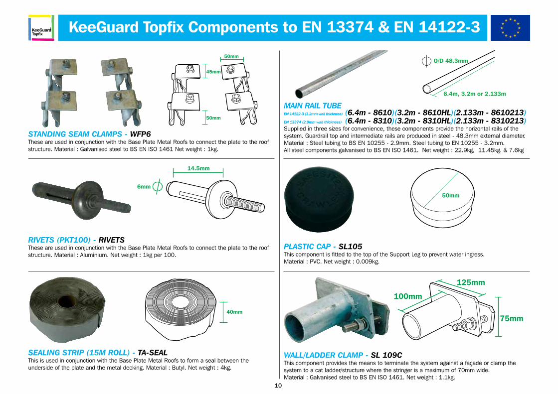
WALL/LADDER CLAMP - SL 109CThis component provides the means to terminate the system against a façade or clamp thesystem to a cat ladder/structure where the stringer is a maximum of 70mm wide.Material : Galvanised steel to BS EN ISO 1461. Net weight : 1.1kg.
100mm
125mm
75mm
50mm
45mm
50mm
STANDING SEAM CLAMPS - WFP6These are used in conjunction with the Base Plate Metal Roofs to connect the plate to the roof structure. Material : Galvanised steel to BS EN ISO 1461 Net weight : 1kg.
RIVETS (PKT100) - RIVETSThese are used in conjunction with the Base Plate Metal Roofs to connect the plate to the roof structure. Material : Aluminium. Net weight : 1kg per 100.
6mm
14.5mm
SEALING STRIP (15M ROLL) - TA-SEALThis is used in conjunction with the Base Plate Metal Roofs to form a seal between theunderside of the plate and the metal decking. Material : Butyl. Net weight : 4kg.
40mm
MAIN RAIL TUBEEN 14122-3 (3.2mm wall thickness) (6.4m - 8610)(3.2m - 8610HL)(2.133m - 8610213)EN 13374 (2.9mm wall thickness) (6.4m - 8310)(3.2m - 8310HL)(2.133m - 8310213)Supplied in three sizes for convenience, these components provide the horizontal rails of the system. Guardrail top and intermediate rails are produced in steel - 48.3mm external diameter.Material : Steel tubing to BS EN 10255 - 2.9mm. Steel tubing to EN 10255 - 3.2mm. All steel components galvanised to BS EN ISO 1461. Net weight : 22.9kg, 11.45kg. & 7.6kg
O/D 48.3mm
6.4m, 3.2m or 2.133m
50mm
PLASTIC CAP - SL105This component is fitted to the top of the Support Leg to prevent water ingress. Material : PVC. Net weight : 0.009kg.
11
KeeGuardTopfix
* Sold as replacement parts only
KeeGuard Topfix Components to EN 13374 & EN 14122-3
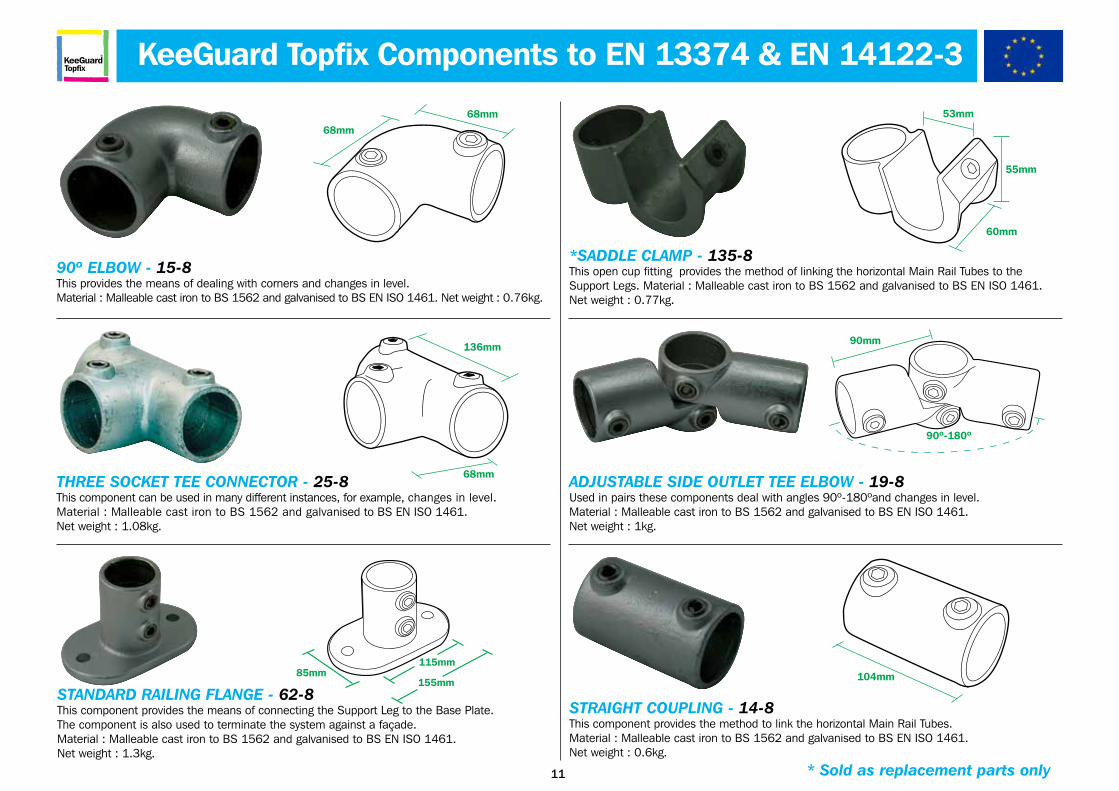
68mm
68mm
90º ELBOW - 15-8This provides the means of dealing with corners and changes in level.Material : Malleable cast iron to BS 1562 and galvanised to BS EN ISO 1461. Net weight : 0.76kg.
THREE SOCKET TEE CONNECTOR - 25-8This component can be used in many different instances, for example, changes in level.Material : Malleable cast iron to BS 1562 and galvanised to BS EN ISO 1461.Net weight : 1.08kg.
136mm
68mm
STANDARD RAILING FLANGE - 62-8This component provides the means of connecting the Support Leg to the Base Plate.The component is also used to terminate the system against a façade.Material : Malleable cast iron to BS 1562 and galvanised to BS EN ISO 1461. Net weight : 1.3kg.
115mm
155mm85mm
53mm
55mm
60mm
*SADDLE CLAMP - 135-8This open cup fitting provides the method of linking the horizontal Main Rail Tubes to theSupport Legs. Material : Malleable cast iron to BS 1562 and galvanised to BS EN ISO 1461.Net weight : 0.77kg.
90mm
90º-180º
ADJUSTABLE SIDE OUTLET TEE ELBOW - 19-8Used in pairs these components deal with angles 90º-180ºand changes in level.Material : Malleable cast iron to BS 1562 and galvanised to BS EN ISO 1461.Net weight : 1kg.
STRAIGHT COUPLING - 14-8This component provides the method to link the horizontal Main Rail Tubes.Material : Malleable cast iron to BS 1562 and galvanised to BS EN ISO 1461.Net weight : 0.6kg.
104mm
12
KeeGuardTopfix
KeeGuard Topfix Components to EN 13374 & EN 14122-3
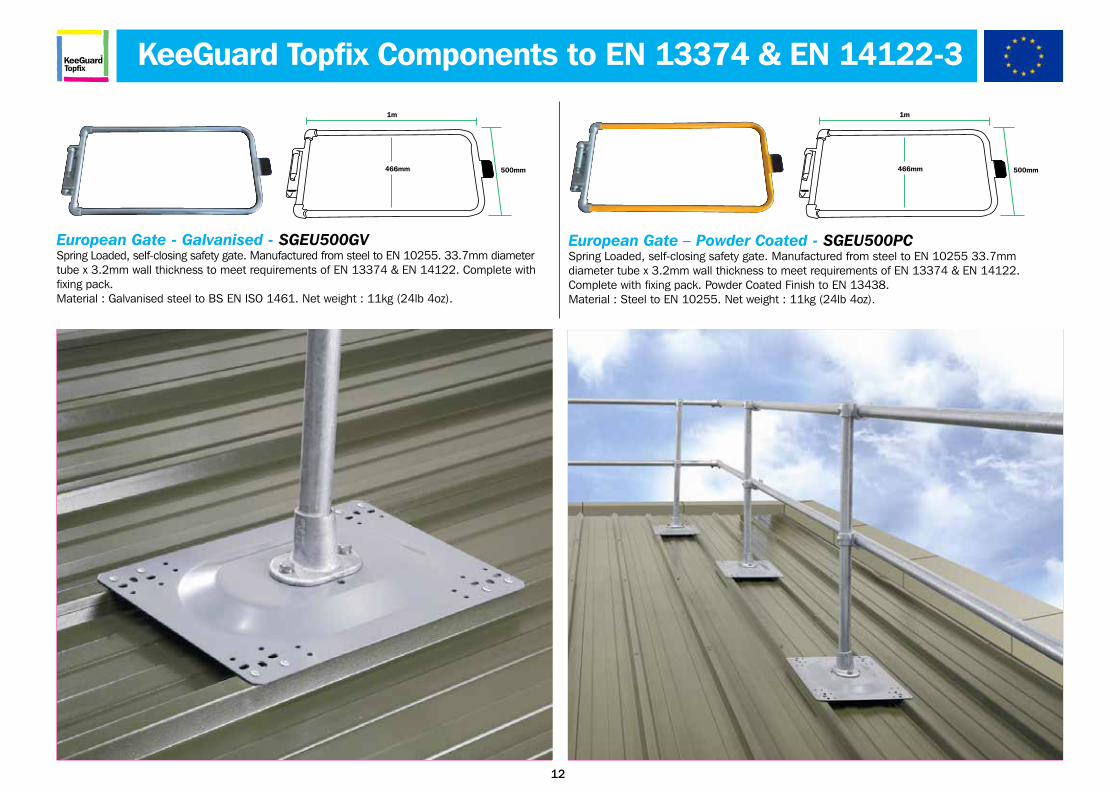
European Gate - Galvanised - SGEU500GVSpring Loaded, self-closing safety gate. Manufactured from steel to EN 10255. 33.7mm diameter tube x 3.2mm wall thickness to meet requirements of EN 13374 & EN 14122. Complete with fixing pack.Material : Galvanised steel to BS EN ISO 1461. Net weight : 11kg (24lb 4oz).
466mm
1m
500mm 466mm
1m
500mm
European Gate – Powder Coated - SGEU500PCSpring Loaded, self-closing safety gate. Manufactured from steel to EN 10255 33.7mmdiameter tube x 3.2mm wall thickness to meet requirements of EN 13374 & EN 14122.Complete with fixing pack. Powder Coated Finish to EN 13438. Material : Steel to EN 10255. Net weight : 11kg (24lb 4oz).
17
KeeGuardTopfix
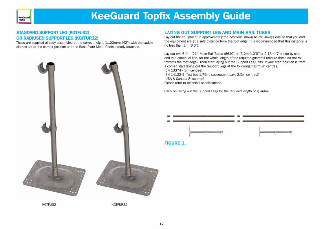
STANDARD SUPPORT LEG (KGTFU32)OR RADIUSED SUPPORT LEG (KGTFUR32)These are supplied already assembled at the correct height (1100mm) (42”) with the saddle clamps set at the correct position and the Base Plate Metal Roofs already attached.
LAYING OUT SUPPORT LEG AND MAIN RAIL TUBESLay out the equipment in approximately the positions shown below. Always ensure that you and the equipment are at a safe distance from the roof edge. It is recommended that this distance is no less than 2m (6’6”).
Lay out two 6.4m (21’) Main Rail Tubes (8610) or (3.2m (10’6”)or 2.13m (7’)) side by side and in a continual line, for the whole length of the required guardrail (ensure these do not roll towards the roof edge). Then start laying out the Support Leg Units. If your start position is from a corner, start laying out the Support Legs at the following maximum centres.(EN 13374 - 3m centres)(EN 14122-3 (first bay 1.75m, subsequent bays 2.5m centres))(USA & Canada 8’ centres)Please refer to technical specifications.
Carry on laying out the Support Legs for the required length of guardrail.
FIGURE 1.
KGTFU32 KGTFUR32
KeeGuard Topfix Assembly Guide
18
KeeGuardTopfix
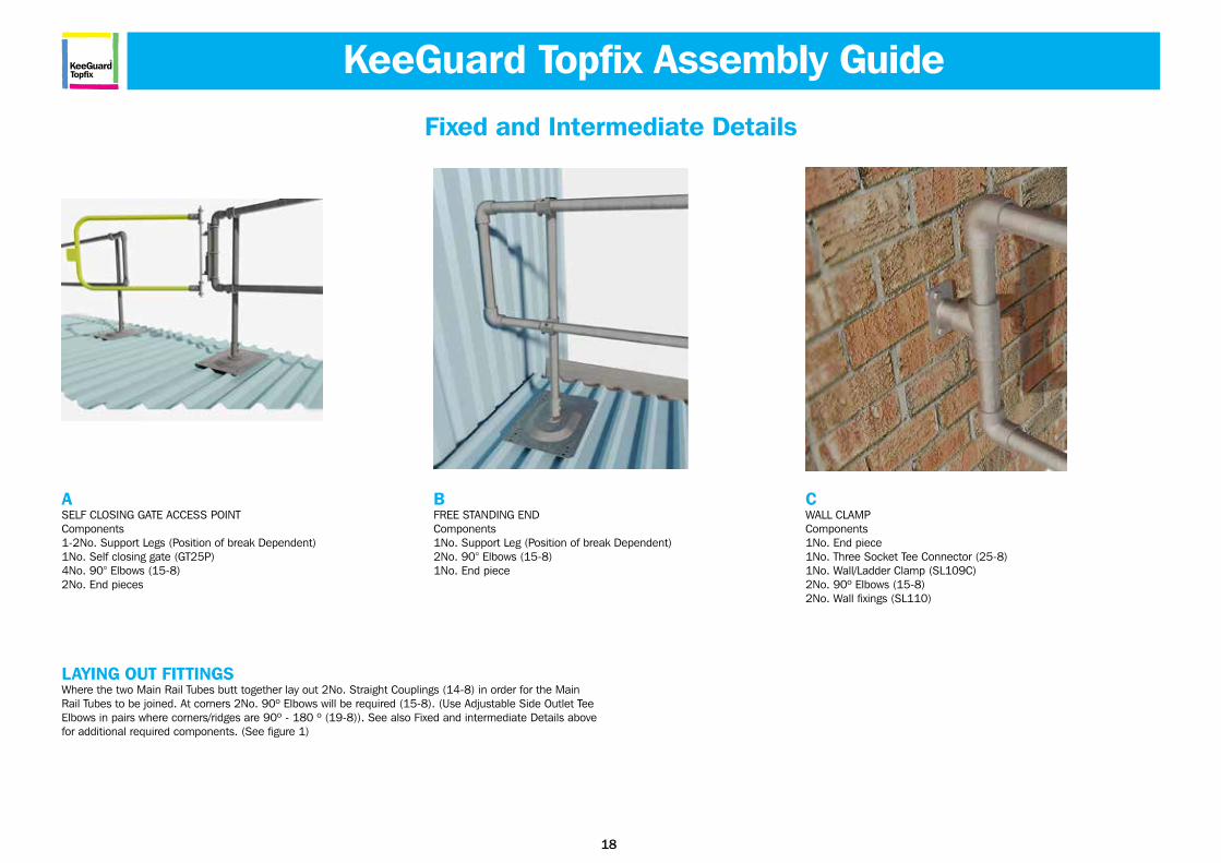
ASELF CLOSING GATE ACCESS POINTComponents1-2No. Support Legs (Position of break Dependent)1No. Self closing gate (GT25P)4No. 90° Elbows (15-8)2No. End pieces
BFREE STANDING ENDComponents1No. Support Leg (Position of break Dependent)2No. 90° Elbows (15-8)1No. End piece
CWALL CLAMPComponents1No. End piece1No. Three Socket Tee Connector (25-8)1No. Wall/Ladder Clamp (SL109C)2No. 90º Elbows (15-8)2No. Wall fixings (SL110)
Fixed and Intermediate Details
LAYING OUT FITTINGSWhere the two Main Rail Tubes butt together lay out 2No. Straight Couplings (14-8) in order for the Main Rail Tubes to be joined. At corners 2No. 90º Elbows will be required (15-8). (Use Adjustable Side Outlet Tee Elbows in pairs where corners/ridges are 90º - 180 º (19-8)). See also Fixed and intermediate Details above for additional required components. (See figure 1)
KeeGuard Topfix Assembly Guide
19
KeeGuardTopfix
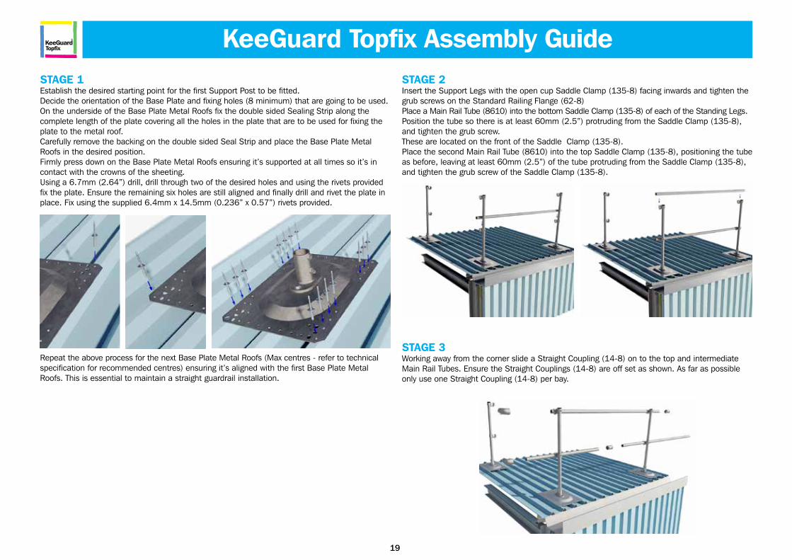
STAGE 1Establish the desired starting point for the first Support Post to be fitted.Decide the orientation of the Base Plate and fixing holes (8 minimum) that are going to be used.On the underside of the Base Plate Metal Roofs fix the double sided Sealing Strip along the complete length of the plate covering all the holes in the plate that are to be used for fixing the plate to the metal roof.Carefully remove the backing on the double sided Seal Strip and place the Base Plate Metal Roofs in the desired position. Firmly press down on the Base Plate Metal Roofs ensuring it’s supported at all times so it’s in contact with the crowns of the sheeting.Using a 6.7mm (2.64”) drill, drill through two of the desired holes and using the rivets provided fix the plate. Ensure the remaining six holes are still aligned and finally drill and rivet the plate in place. Fix using the supplied 6.4mm x 14.5mm (0.236” x 0.57”) rivets provided.
Repeat the above process for the next Base Plate Metal Roofs (Max centres - refer to technicalspecification for recommended centres) ensuring it’s aligned with the first Base Plate Metal Roofs. This is essential to maintain a straight guardrail installation.
STAGE 2Insert the Support Legs with the open cup Saddle Clamp (135-8) facing inwards and tighten the grub screws on the Standard Railing Flange (62-8)Place a Main Rail Tube (8610) into the bottom Saddle Clamp (135-8) of each of the Standing Legs. Position the tube so there is at least 60mm (2.5”) protruding from the Saddle Clamp (135-8), and tighten the grub screw.These are located on the front of the Saddle Clamp (135-8).Place the second Main Rail Tube (8610) into the top Saddle Clamp (135-8), positioning the tube as before, leaving at least 60mm (2.5”) of the tube protruding from the Saddle Clamp (135-8), and tighten the grub screw of the Saddle Clamp (135-8).
STAGE 3Working away from the corner slide a Straight Coupling (14-8) on to the top and intermediate Main Rail Tubes. Ensure the Straight Couplings (14-8) are off set as shown. As far as possible only use one Straight Coupling (14-8) per bay.
KeeGuard Topfix Assembly Guide
20
KeeGuardTopfix
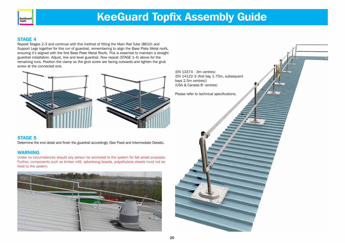
STAGE 4Repeat Stages 2-3 and continue with this method of fitting the Main Rail Tube (8610) and Support Legs together for this run of guardrail, remembering to align the Base Plate Metal roofs, ensuring it’s aligned with the first Base Plate Metal Roofs. This is essential to maintain a straight guardrail installation. Adjust, line and level guardrail. Now repeat (STAGE 1-4) above for the remaining runs. Position the clamp so the grub screw are facing outwards and tighten the grub screw at the connected end.
STAGE 5Determine the end detail and finish the guardrail accordingly (See Fixed and Intermediate Details).
WARNINGUnder no circumstances should any person be anchored to the system for fall arrest purposes. Further, components such as timber infill, advertising boards, polyethylene sheets must not be fixed to the system.
KeeGuard Topfix Assembly Guide
(EN 13374 - 3m centres)(EN 14122-3 (first bay 1.75m, subsequent bays 2.5m centres))(USA & Canada 8’ centres)
Please refer to technical specifications.
22
KeeGuardTopfix
• Periodic inspections by a competent person are recommended by the manufacturer. In UK/Europe these are required under Regulation 5 of the Workplace (Health, Safety & Welfare) Regulations, the Work at Height Regulations and BS EN 365. The frequency will depend upon the environment, location and usage but should be at least every 12 months.
• Walk and visually inspect the complete installed system in relation to the general client’s needs. Establish if any modifications and/or additional products are required to reflect any refurbishment requirements or additional plant & equipment which have been installed and require access.
• Check installation configuration is complete as per the original installation drawing/plan.
• Ensure the system has not been modified or tampered with by unauthorised persons.
• Check all rivets connecting Base Plate Metal Roofs.
• Check all grub screws are in place, greased and sufficiently torque.
• Check that the general height and level of the system including the leg centres. (This only tends to be an issue if the system has been tampered with between inspections).
• Any galvanised components showing signs of corrosion should be wire brushed thoroughly and galvanised spray/paint applied as appropriate. If rusted significantly, take digital photographs and include these in the inspection report.
• Where toe-boards are fitted check the brackets that support the toe-board are in place, greased and sufficiently torqued.
• Where applicable, check fixings to walls/structures including cat ladder clamps are in place, greased and sufficiently torqued.
• Check system plaque position & mark up to reflect date of the next required inspection. Establish if additional plaques are required due to any refurbishment works.
Guardrail Systems Recertification
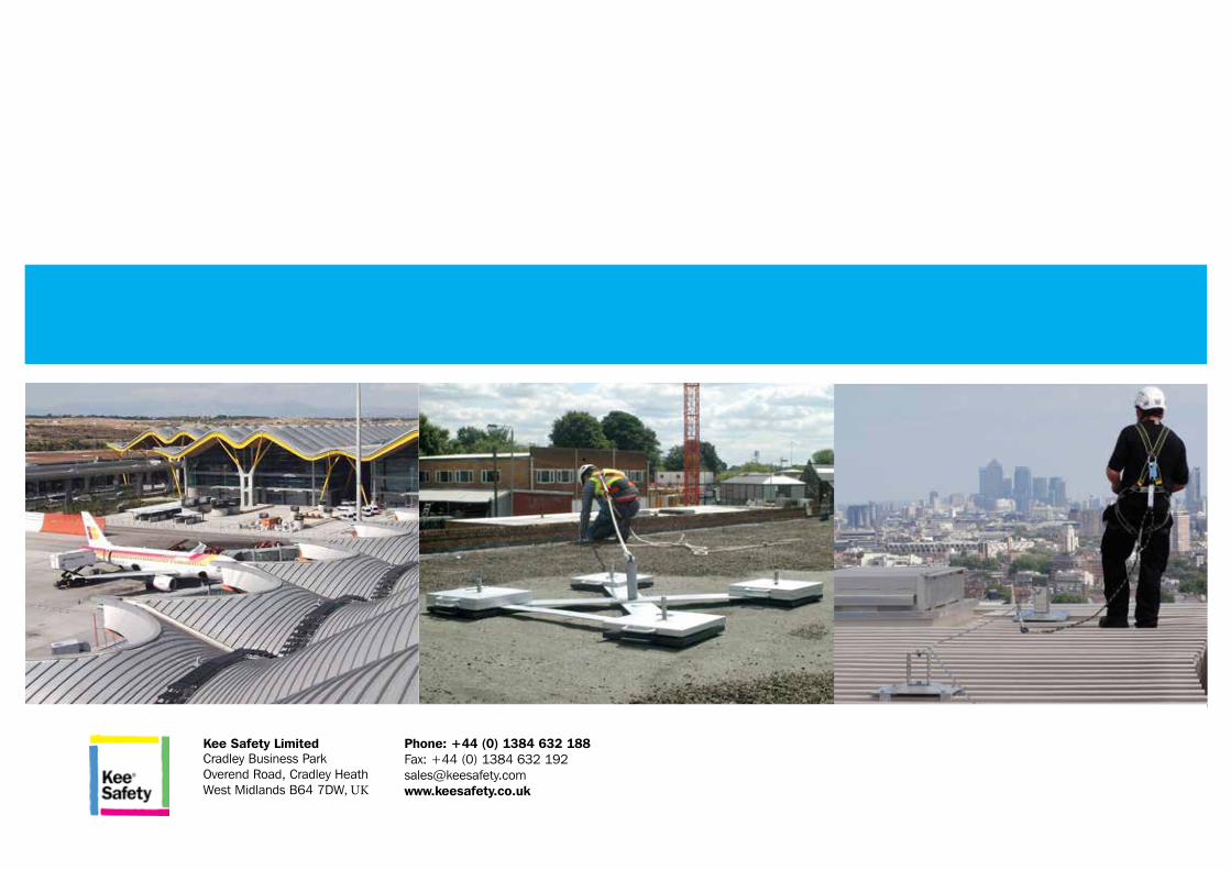
Kee Safety Limited Cradley Business Park Overend Road, Cradley Heath West Midlands B64 7DW, UK
Phone: +44 (0) 1384 632 188Fax: +44 (0) 1384 632 [email protected]


![Installation TopFix / RecessFix [R1] Model [R1] XXL · 2017. 8. 29. · Model Installation and Use r ... Footplate installation (top) 2 Footplate installation (bottom) 4 Operation](https://img.pdfslide.net/doc/110x75/5ffc87463757ea188c1819f4/installation-topfix-recessfix-r1-model-r1-xxl-2017-8-29-model-installation.jpg)

![Installation TopFix / RecessFix [R1] · Installation TopFix / RecessFix [R1] Young children can be strangled by loops in pull cords, chains, tapes and inner cords that operate the](https://img.pdfslide.net/doc/110x75/5ede9722ad6a402d6669ead9/installation-topfix-recessfix-r1-installation-topfix-recessfix-r1-young.jpg)