Embed Size (px)
Citation preview
1
Keko Equipment NEWSLETTERNO. 2 NOVEMBER 2003
2
Development Strategy 3
Technology News 5
Development Projects 9
Market Situation 10
Highlights 14
Company Profile 16
In the interplay of time and space opportunities and coincidences meet.At this juncture the intermingling of knowledge and vision pursues happiness.
When experience and boldness look out for development, a path opens into the future.
3
insight
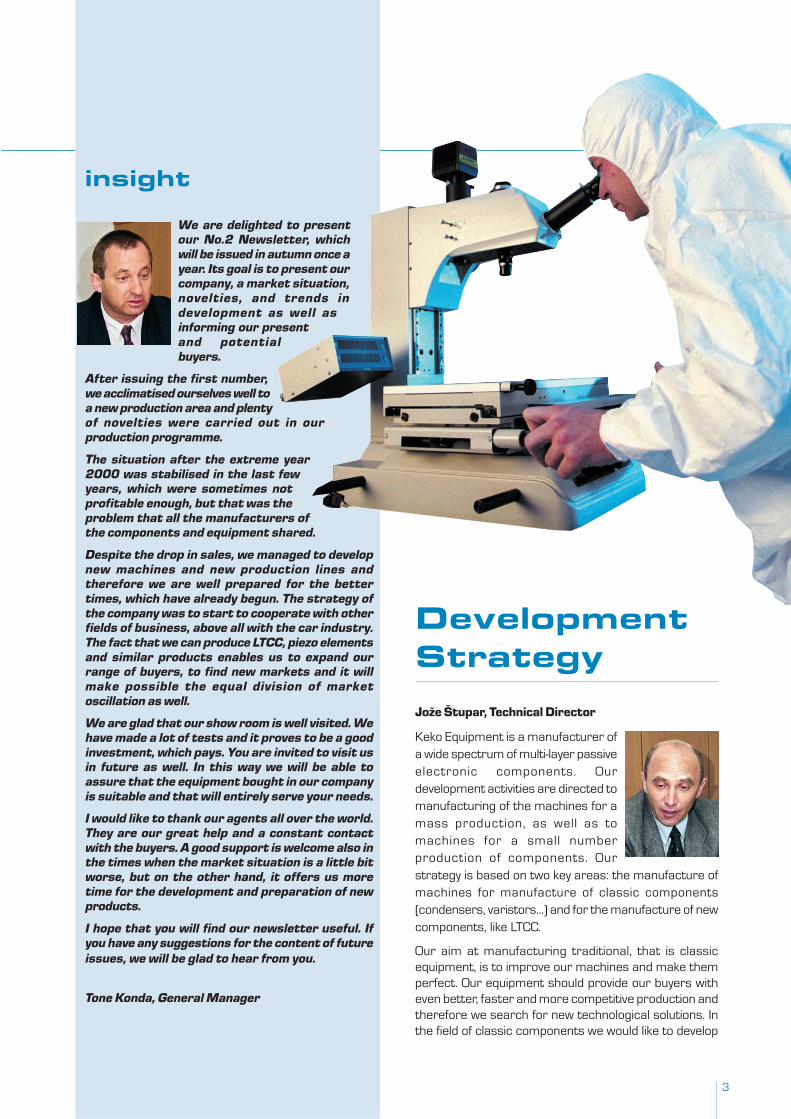
We are delighted to presentour No.2 Newsletter, whichwill be issued in autumn once ayear. Its goal is to present ourcompany, a market situation,novelties, and trends indevelopment as well asinforming our presentand potentialbuyers.
After issuing the first number,we acclimatised ourselves well toa new production area and plentyof novelties were carried out in ourproduction programme.
The situation after the extreme year2000 was stabilised in the last fewyears, which were sometimes notprofitable enough, but that was theproblem that all the manufacturers ofthe components and equipment shared.
Despite the drop in sales, we managed to developnew machines and new production lines andtherefore we are well prepared for the bettertimes, which have already begun. The strategy ofthe company was to start to cooperate with otherfields of business, above all with the car industry.The fact that we can produce LTCC, piezo elementsand similar products enables us to expand ourrange of buyers, to find new markets and it willmake possible the equal division of marketoscillation as well.
We are glad that our show room is well visited. Wehave made a lot of tests and it proves to be a goodinvestment, which pays. You are invited to visit usin future as well. In this way we will be able toassure that the equipment bought in our companyis suitable and that will entirely serve your needs.
I would like to thank our agents all over the world.They are our great help and a constant contactwith the buyers. A good support is welcome also inthe times when the market situation is a little bitworse, but on the other hand, it offers us moretime for the development and preparation of newproducts.
I hope that you will find our newsletter useful. Ifyou have any suggestions for the content of futureissues, we will be glad to hear from you.
Tone Konda, General Manager
DevelopmentStrategy
Jože Štupar, Technical Director
Keko Equipment is a manufacturer ofa wide spectrum of multi-layer passiveelectronic components. Ourdevelopment activities are directed tomanufacturing of the machines for amass production, as well as tomachines for a small numberproduction of components. Ourstrategy is based on two key areas: the manufacture ofmachines for manufacture of classic components(condensers, varistors…) and for the manufacture of newcomponents, like LTCC.
Our aim at manufacturing traditional, that is classicequipment, is to improve our machines and make themperfect. Our equipment should provide our buyers witheven better, faster and more competitive production andtherefore we search for new technological solutions. Inthe field of classic components we would like to develop
4
Experience, written in people and daring, based on concord, makes the objectives clear.
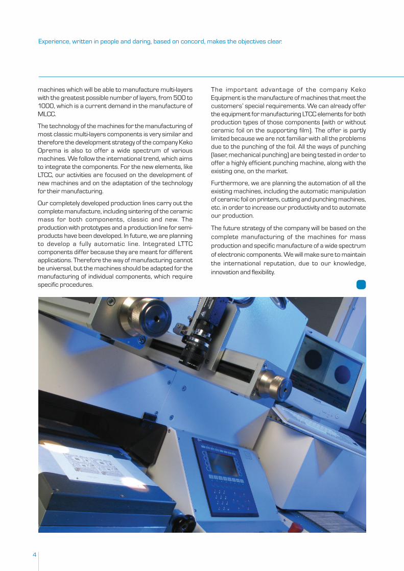
machines which will be able to manufacture multi-layerswith the greatest possible number of layers, from 500 to1000, which is a current demand in the manufacture ofMLCC.
The technology of the machines for the manufacturing ofmost classic multi-layers components is very similar andtherefore the development strategy of the company KekoOprema is also to offer a wide spectrum of variousmachines. We follow the international trend, which aimsto integrate the components. For the new elements, likeLTCC, our activities are focused on the development ofnew machines and on the adaptation of the technologyfor their manufacturing.
Our completely developed production lines carry out thecomplete manufacture, including sintering of the ceramicmass for both components, classic and new. Theproduction with prototypes and a production line for semi-products have been developed. In future, we are planningto develop a fully automatic line. Integrated LTTCcomponents differ because they are meant for differentapplications. Therefore the way of manufacturing cannotbe universal, but the machines should be adapted for themanufacturing of individual components, which requirespecific procedures.
The important advantage of the company KekoEquipment is the manufacture of machines that meet thecustomers’ special requirements. We can already offerthe equipment for manufacturing LTCC elements for bothproduction types of those components (with or withoutceramic foil on the supporting film). The offer is partlylimited because we are not familiar with all the problemsdue to the punching of the foil. All the ways of punching(laser, mechanical punching) are being tested in order tooffer a highly efficient punching machine, along with theexisting one, on the market.
Furthermore, we are planning the automation of all theexisting machines, including the automatic manipulationof ceramic foil on printers, cutting and punching machines,etc. in order to increase our productivity and to automateour production.
The future strategy of the company will be based on thecomplete manufacturing of the machines for massproduction and specific manufacture of a wide spectrumof electronic components. We will make sure to maintainthe international reputation, due to our knowledge,innovation and flexibility.
5
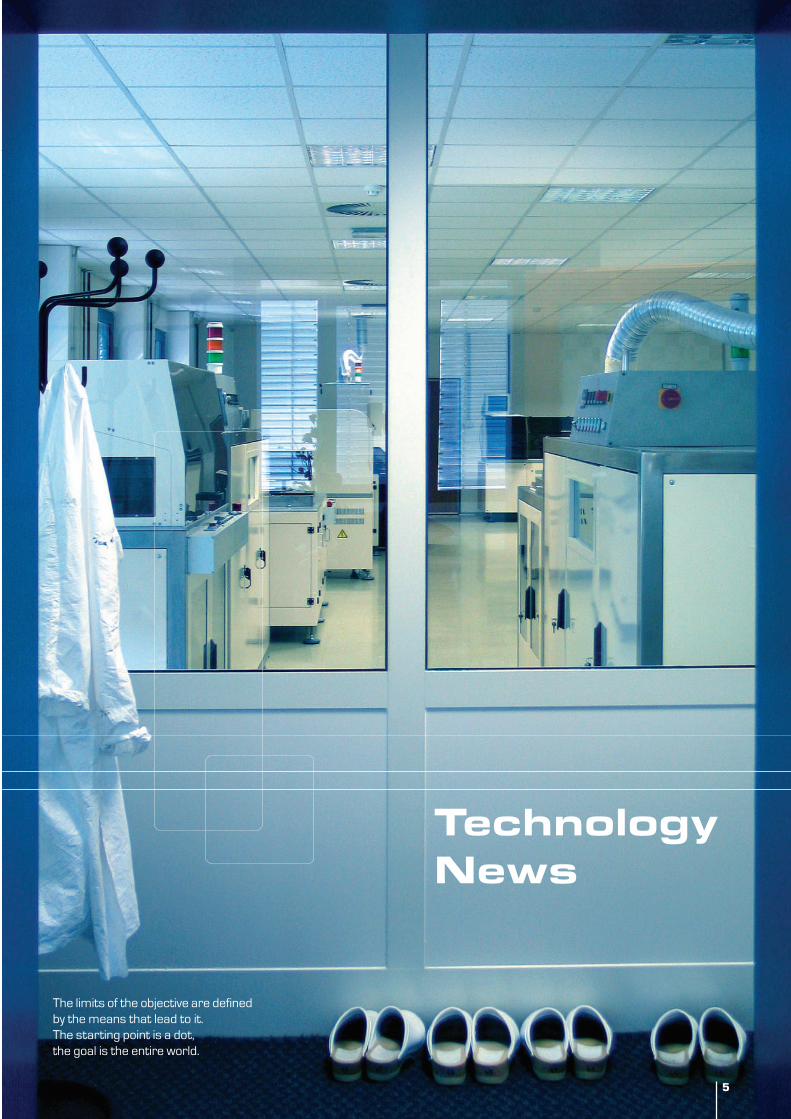
The limits of the objective are definedby the means that lead to it.The starting point is a dot,the goal is the entire world.
5
TechnologyNews
6
LTCCProduction
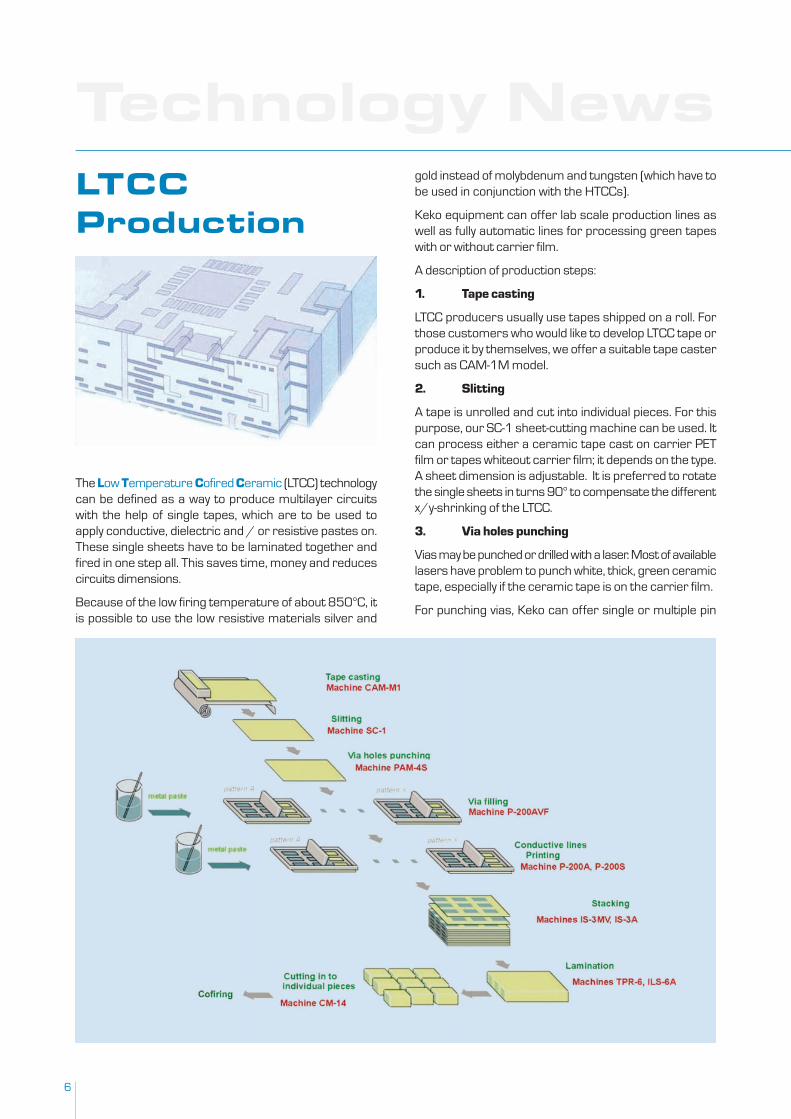
The Low Temperature Cofired Ceramic (LTCC) technologycan be defined as a way to produce multilayer circuitswith the help of single tapes, which are to be used toapply conductive, dielectric and / or resistive pastes on.These single sheets have to be laminated together andfired in one step all. This saves time, money and reducescircuits dimensions.
Because of the low firing temperature of about 850°C, itis possible to use the low resistive materials silver and
gold instead of molybdenum and tungsten (which have tobe used in conjunction with the HTCCs).
Keko equipment can offer lab scale production lines aswell as fully automatic lines for processing green tapeswith or without carrier film.
A description of production steps:
1. Tape casting
LTCC producers usually use tapes shipped on a roll. Forthose customers who would like to develop LTCC tape orproduce it by themselves, we offer a suitable tape castersuch as CAM-1M model.
2. Slitting
A tape is unrolled and cut into individual pieces. For thispurpose, our SC-1 sheet-cutting machine can be used. Itcan process either a ceramic tape cast on carrier PETfilm or tapes whiteout carrier film; it depends on the type.A sheet dimension is adjustable. It is preferred to rotatethe single sheets in turns 90° to compensate the differentx/y-shrinking of the LTCC.
3. Via holes punching
Vias may be punched or drilled with a laser. Most of availablelasers have problem to punch white, thick, green ceramictape, especially if the ceramic tape is on the carrier film.
For punching vias, Keko can offer single or multiple pin
Technology News
7The world of the people and the world of the objects. The path written in the ending. The knowledge preserved in the product.
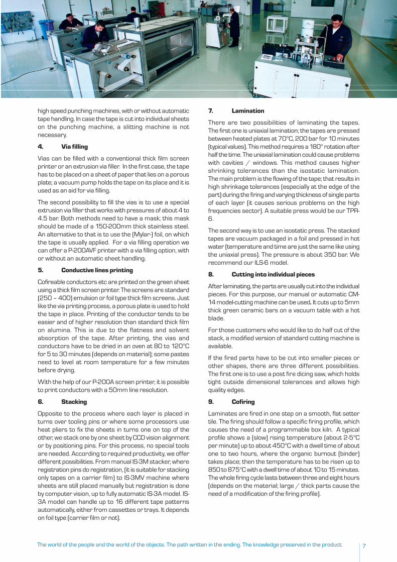
high speed punching machines, with or without automatictape handling. In case the tape is cut into individual sheetson the punching machine, a slitting machine is notnecessary.
4. Via filling
Vias can be filled with a conventional thick film screenprinter or an extrusion via filler. In the first case, the tapehas to be placed on a sheet of paper that lies on a porousplate; a vacuum pump holds the tape on its place and it isused as an aid for via filling.
The second possibility to fill the vias is to use a specialextrusion via filler that works with pressures of about 4 to4.5 bar. Both methods need to have a mask; this maskshould be made of a 150-200mm thick stainless steel.An alternative to that is to use the (Mylar-) foil, on whichthe tape is usually applied. For a via filling operation wecan offer a P-200AVF printer with a via filling option, withor without an automatic sheet handling.
5. Conductive lines printing
Cofireable conductors etc are printed on the green sheetusing a thick film screen printer. The screens are standard(250 – 400) emulsion or foil type thick film screens. Justlike the via printing process, a porous plate is used to holdthe tape in place. Printing of the conductor tends to beeasier and of higher resolution than standard thick filmon alumina. This is due to the flatness and solventabsorption of the tape. After printing, the vias andconductors have to be dried in an oven at 80 to 120°Cfor 5 to 30 minutes (depends on material); some pastesneed to level at room temperature for a few minutesbefore drying.
With the help of our P-200A screen printer, it is possibleto print conductors with a 50mm line resolution.
6. Stacking
Opposite to the process where each layer is placed inturns over tooling pins or where some processors useheat pliers to fix the sheets in turns one on top of theother, we stack one by one sheet by CCD vision alignmentor by positioning pins. For this process, no special toolsare needed. According to required productivity, we offerdifferent possibilities. From manual IS-3M stacker, whereregistration pins do registration, (it is suitable for stackingonly tapes on a carrier film) to IS-3MV machine wheresheets are still placed manually but registration is doneby computer vision, up to fully automatic IS-3A model. IS-3A model can handle up to 16 different tape patternsautomatically, either from cassettes or trays. It dependson foil type (carrier film or not).
7. Lamination
There are two possibilities of laminating the tapes.The first one is uniaxial lamination; the tapes are pressedbetween heated plates at 70°C, 200 bar for 10 minutes(typical values). This method requires a 180° rotation afterhalf the time. The uniaxial lamination could cause problemswith cavities / windows. This method causes highershrinking tolerances than the isostatic lamination.The main problem is the flowing of the tape; that results inhigh shrinkage tolerances (especially at the edge of thepart) during the firing and varying thickness of single partsof each layer (it causes serious problems on the highfrequencies sector). A suitable press would be our TPR-6.
The second way is to use an isostatic press. The stackedtapes are vacuum packaged in a foil and pressed in hotwater (temperature and time are just the same like usingthe uniaxial press). The pressure is about 350 bar. Werecommend our ILS-6 model.
8. Cutting into individual pieces
After laminating, the parts are usually cut into the individualpieces. For this purpose, our manual or automatic CM-14 model-cutting machine can be used. . . . . It cuts up to 5mmthick green ceramic bars on a vacuum table with a hotblade.
For those customers who would like to do half cut of thestack, a modified version of standard cutting machine isavailable.
If the fired parts have to be cut into smaller pieces orother shapes, there are three different possibilities.The first one is to use a post fire dicing saw, which holdstight outside dimensional tolerances and allows highquality edges.
9. Cofiring
Laminates are fired in one step on a smooth, flat settertile. The firing should follow a specific firing profile, whichcauses the need of a programmable box kiln. A typicalprofile shows a (slow) rising temperature (about 2-5°Cper minute) up to about 450°C with a dwell time of aboutone to two hours, where the organic burnout (binder)takes place; then the temperature has to be risen up to850 to 875°C with a dwell time of about 10 to 15 minutes.The whole firing cycle lasts between three and eight hours(depends on the material; large / thick parts cause theneed of a modification of the firing profile).
8
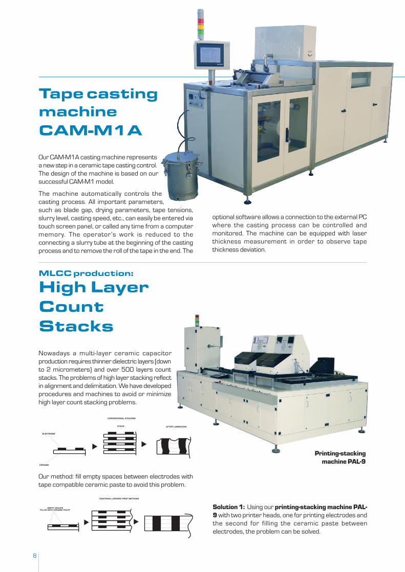
Tape castingmachineCAM-M1A
Our CAM-M1A casting machine representsa new step in a ceramic tape casting control.The design of the machine is based on oursuccessful CAM-M1 model.
The machine automatically controls thecasting process. All important parameters,such as blade gap, drying parameters, tape tensions,slurry level, casting speed, etc., can easily be entered viatouch screen panel, or called any time from a computermemory. The operator’s work is reduced to theconnecting a slurry tube at the beginning of the castingprocess and to remove the roll of the tape in the end. The
optional software allows a connection to the external PCwhere the casting process can be controlled andmonitored. The machine can be equipped with laserthickness measurement in order to observe tapethickness deviation.
MLCC production:
High LayerCountStacks
Nowadays a multi-layer ceramic capacitorproduction requires thinner dielectric layers (downto 2 micrometers) and over 500 layers countstacks. The problems of high layer stacking reflectin alignment and delimitation. We have developedprocedures and machines to avoid or minimizehigh layer count stacking problems.
ELECTRODE
CERAMIC
AFTER LAMINATIONSTACK
CONVENTIONAL STACKING
EMPTY SPACESFILLED WITH CERAMIC PASTE
ADDITIONAL CERAMIC PRINT METHODE
Our method: fill empty spaces between electrodes withtape compatible ceramic paste to avoid this problem.
Solution 1: Using our printing-stacking machine PAL-9 with two printer heads, one for printing electrodes andthe second for filling the ceramic paste betweenelectrodes, the problem can be solved.
Printing-stackingmachine PAL-9
9
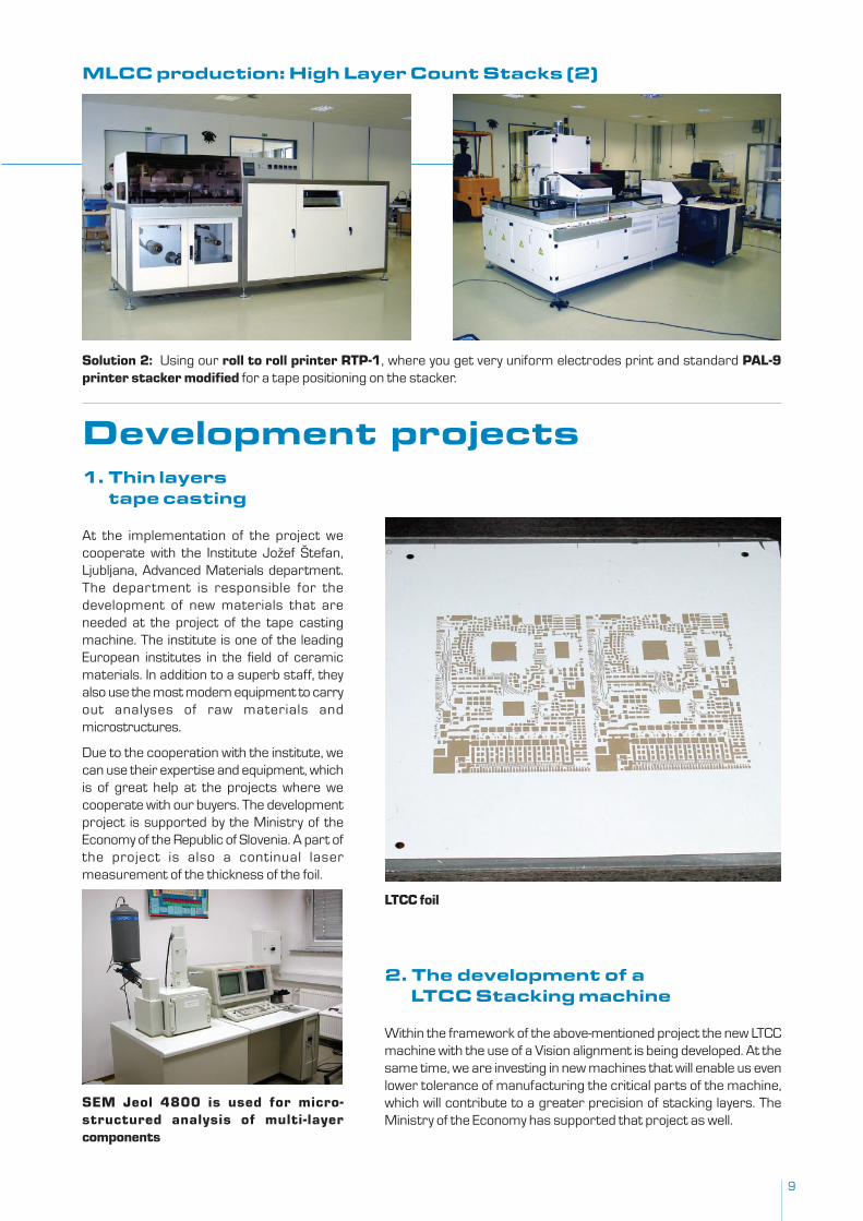
Solution 2: Using our roll to roll printer RTP-1, where you get very uniform electrodes print and standard PAL-9printer stacker modified for a tape positioning on the stacker.
MLCC production: High Layer Count Stacks (2)
1. Thin layerstape casting
At the implementation of the project wecooperate with the Institute Jožef Štefan,Ljubljana, Advanced Materials department.The department is responsible for thedevelopment of new materials that areneeded at the project of the tape castingmachine. The institute is one of the leadingEuropean institutes in the field of ceramicmaterials. In addition to a superb staff, theyalso use the most modern equipment to carryout analyses of raw materials andmicrostructures.
Due to the cooperation with the institute, wecan use their expertise and equipment, whichis of great help at the projects where wecooperate with our buyers. The developmentproject is supported by the Ministry of theEconomy of the Republic of Slovenia. A part ofthe project is also a continual lasermeasurement of the thickness of the foil.
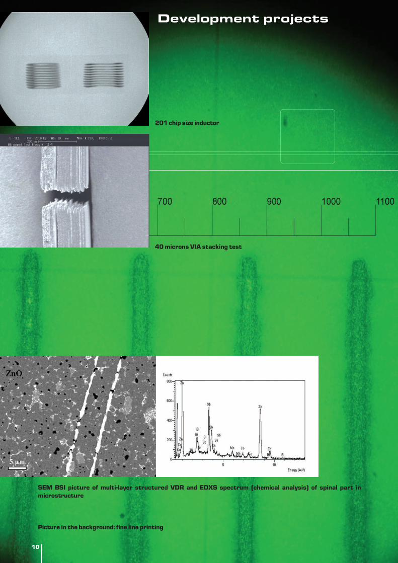
Development projects
2. The development of aLTCC Stacking machine
Within the framework of the above-mentioned project the new LTCCmachine with the use of a Vision alignment is being developed. At thesame time, we are investing in new machines that will enable us evenlower tolerance of manufacturing the critical parts of the machine,which will contribute to a greater precision of stacking layers. TheMinistry of the Economy has supported that project as well.
SEM Jeol 4800 is used for micro-structured analysis of multi-layercomponents
LTCC foil
1010
SEM BSI picture of multi-layer structured VDR and EDXS spectrum (chemical analysis) of spinal part inmicrostructure
Picture in the background: fine line printing
40 microns VIA stacking test
201 chip size inductor
Development projects
11
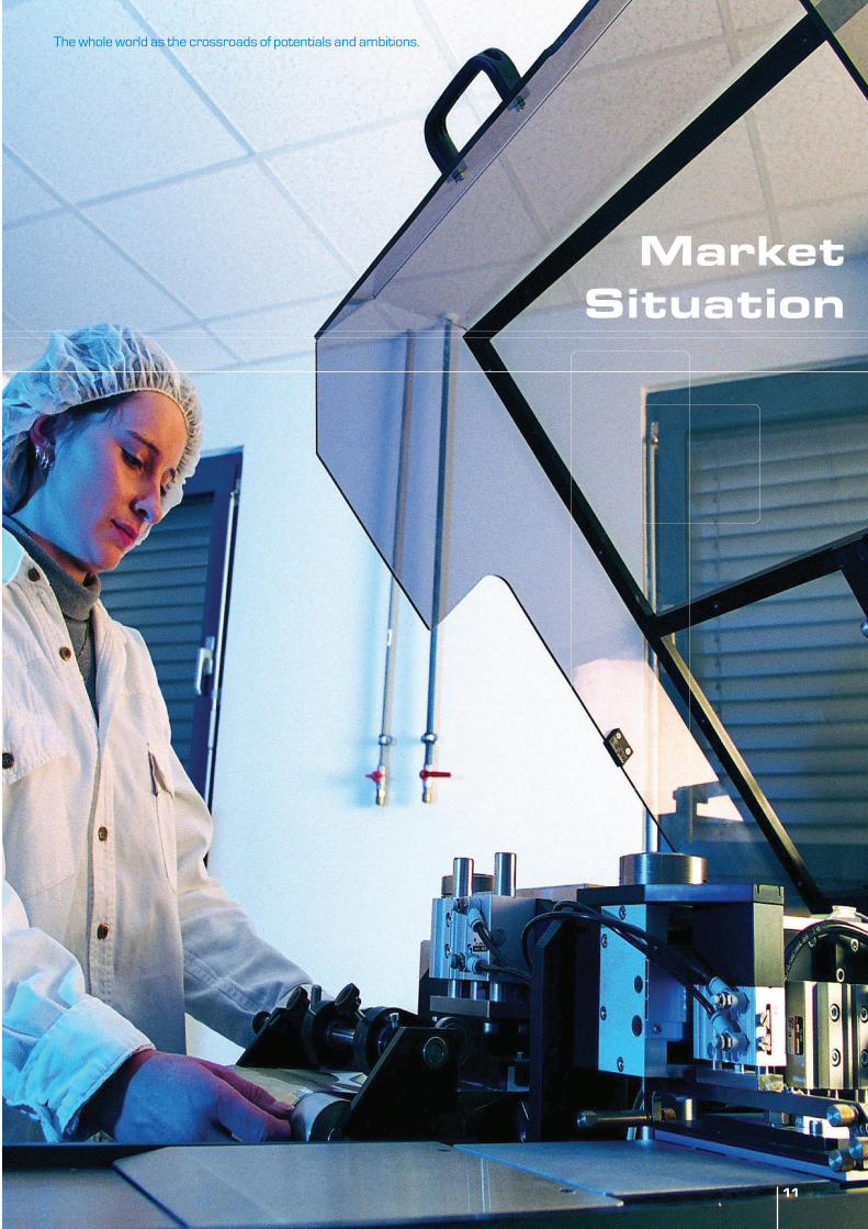
MarketSituation
The whole world as the crossroads of potentials and ambitions.
11
12
Market situationThe spectrum of the machines that we have been tradingwith recently has changed a little bit. The majority ofmanufacturers have already created enough capacitiesfor manufacturing their basic products. Therefore wehave been trading mostly with the machines and lines formanufacturing new components and we have been tryingto improve the quality of manufacturing of the existinglines.
Tape casting machine CAM-M1 has proved a very goodsolution for casting very thin layers (within 5 microns) in asatisfactory casting tolerance. The efficient system ofdrying used for the casting of thick layers which can reachthe thickness of 200 microns and more. Some of thenovelties which are the most important advantages ofthe machine are: the new system for the automaticsetting of the casting blade height, the control of the slurrylevel before the casting blade and last but not least, theattractive price.
Printing-stacking machine PAL-9 is still a machine thathas the best relation between the productivity, precisionin stacking and a price. Its flexibility enables themanufacture of a wide spectrum of products, includingthe total automation of LTCC production.
Cutting machine CM-14: With the improvement of theengineering, the use of the new blade designs togetherwith the use of the new system for fixing a bar, we haveachieved very good results in cutting the small dimensionchips and in cutting the bars of 7 mm thickness as well.
Lines for the production of conductors, LTCC: We havesold some entire lines for LTCC production. The lineincludes the entire procedure, from casting a tape tocutting it into individual pieces, punching, VIA filing, printingof conductors and automatic or manual stacking with thehelp of gases or the vision system. The whole line can alsobe seen in our show room, where several tests can beperformed as well.
PADS FP5 Project
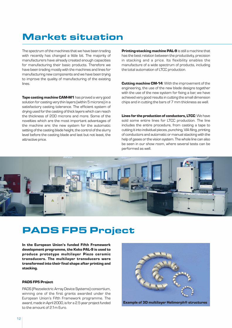
Example of 3D multilayer Helimorph® structures
In the European Union’s funded Fifth Frameworkdevelopment programme, the Keko PAL-9 is used toproduce prototype multilayer Piezo ceramictransducers. The multilayer transducers weretransformed into their final shape after printing andstacking.
PADS FP5 Project
PADS (Piezoelectric Array Device Systems) consortium,winning one of the first grants awarded under theEuropean Union’s Fifth Framework programme. Theaward, made in April 2000, is for a 2.5 year project fundedto the amount of 2.1m Euro.
13
The objective of the Framework programme is tostimulate and encourage the development ofcommercially viable new technologies within the EU,bringing together industry and academia into workingcollaborations.
The PADS consortium comprises:
- Haiku Tech, The Netherlands:
- 1 Limited, UK
- Marconi plc, UK
- Laboratoire des Ondes et Acoustiques (LOA), France
- University of Erlangen-Nuremberg, Germany
- University of Birmingham, UK
- University of Science and Technology (UMIST) inManchester, UK
The target helix shaped actuator is a revolutionarydevelopment in the field of ceramic actuators. Thepatented design of the actuator produces a device that iscompact, lightweight, capable of very large displacements(up to many millimetres) and capable of efficienciesunmatched by comparable electromagnetic motors orsolenoids. Its motion is highly linear, and readily controllablethrough simple-to-implement electronics. The Haiku Techtask has been successful to develop multi-layered ceramicactuator technologies that can be produced in complexhigh layer count 3D-shapes.
Helimorph® devices are made from a tape of two ormore layers of piezoelectric material, which aresurrounded and separated by conductive electrodes toform a bimorph.
The behaviour of a bimorph under an applied voltage islike that of a bimetallic strip exposed to changes intemperature. When a voltage is applied across a bimorphone layer shrinks and the other expands. As the two layersare adhered to one another, this behaviour causes thebimorph to bend.
To form a Helimorph®, a bimorph tape is first wound intoa primary helix.
If a primary Helix were to be activated, the incrementalbending of each segment would result in a slightcontraction or expansion of the helix diameter. In additionto this, one end of the device would rotate relative to theother.
Once the primary helix is formed into a secondary arc, therotation causes one end of the Helimorph® device todisplace linearly relative to the other.
Due to the high displacement of the actuators, acombination of benefits can be achieved like highdisplacement, low power use, fast frictionless silentoperation.
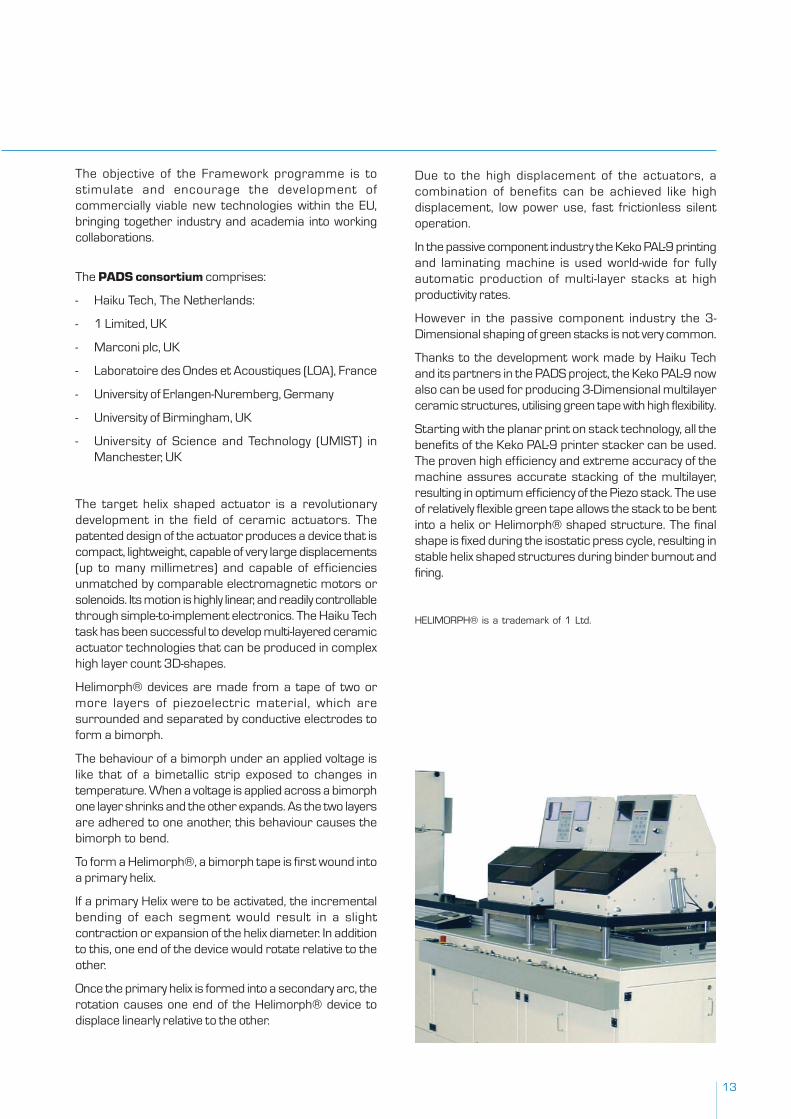
In the passive component industry the Keko PAL-9 printingand laminating machine is used world-wide for fullyautomatic production of multi-layer stacks at highproductivity rates.
However in the passive component industry the 3-Dimensional shaping of green stacks is not very common.
Thanks to the development work made by Haiku Techand its partners in the PADS project, the Keko PAL-9 nowalso can be used for producing 3-Dimensional multilayerceramic structures, utilising green tape with high flexibility.
Starting with the planar print on stack technology, all thebenefits of the Keko PAL-9 printer stacker can be used.The proven high efficiency and extreme accuracy of themachine assures accurate stacking of the multilayer,resulting in optimum efficiency of the Piezo stack. The useof relatively flexible green tape allows the stack to be bentinto a helix or Helimorph® shaped structure. The finalshape is fixed during the isostatic press cycle, resulting instable helix shaped structures during binder burnout andfiring.
HELIMORPH® is a trademark of 1 Ltd.
14
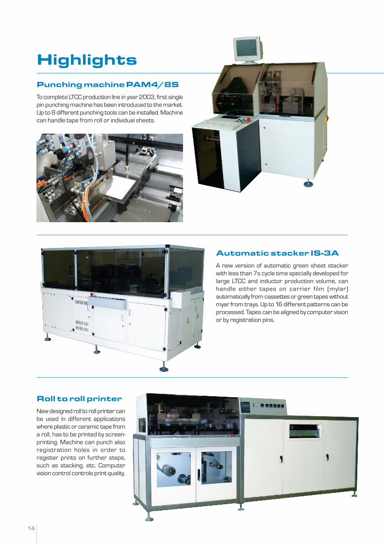
HighlightsPunching machine PAM4/8S
To complete LTCC production line in year 2003, first singlepin punching machine has been introduced to the market.Up to 8 different punching tools can be installed. Machinecan handle tape from roll or individual sheets.
Automatic stacker IS-3A
A new version of automatic green sheet stackerwith less than 7s cycle time specially developed forlarge LTCC and inductor production volume, canhandle either tapes on carrier film (mylar)automatically from cassettes or green tapes withoutmyar from trays. Up to 16 different patterns can beprocessed. Tapes can be aligned by computer visionor by registration pins.
Roll to roll printer
New designed roll to roll printer canbe used in different applicationswhere plastic or ceramic tape froma roll, has to be printed by screen-printing. Machine can punch alsoregistration holes in order toregister prints on further steps,such as stacking, etc. Computervision control controls print quality.
15
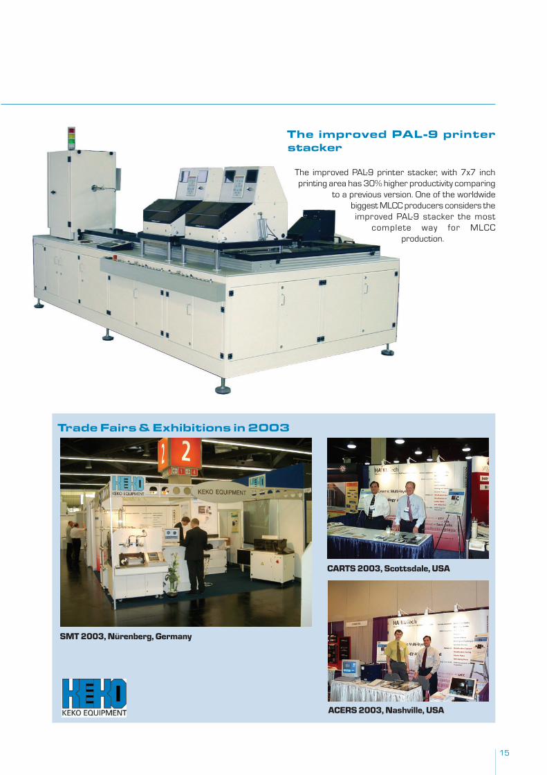
The improved PAL-9 printer stacker, with 7x7 inchprinting area has 30% higher productivity comparing
to a previous version. One of the worldwidebiggest MLCC producers considers theimproved PAL-9 stacker the most
complete way for MLCCproduction.
The improved PAL-9 printerstacker
Trade Fairs & Exhibitions in 2003
SMT 2003, Nürenberg, Germany
CARTS 2003, Scottsdale, USA
ACERS 2003, Nashville, USA
16
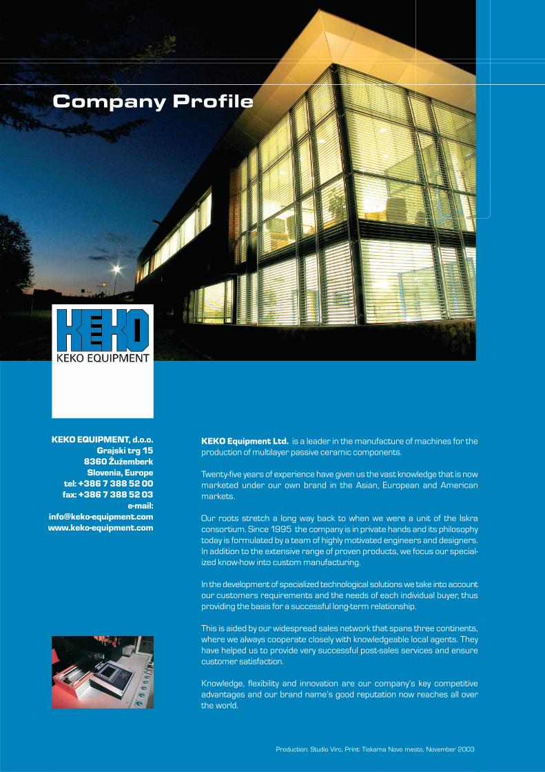
KEKO Equipment Ltd. is a leader in the manufacture of machines for theproduction of multilayer passive ceramic components.
Twenty-five years of experience have given us the vast knowledge that is nowmarketed under our own brand in the Asian, European and Americanmarkets.
Our roots stretch a long way back to when we were a unit of the Iskraconsortium. Since 1995 the company is in private hands and its philosophytoday is formulated by a team of highly motivated engineers and designers.In addition to the extensive range of proven products, we focus our special-ized know-how into custom manufacturing.
In the development of specialized technological solutions we take into accountour customers requirements and the needs of each individual buyer, thusproviding the basis for a successful long-term relationship.
This is aided by our widespread sales network that spans three continents,where we always cooperate closely with knowledgeable local agents. Theyhave helped us to provide very successful post-sales services and ensurecustomer satisfaction.
Knowledge, flexibility and innovation are our company’s key competitiveadvantages and our brand name’s good reputation now reaches all overthe world.
Production: Studio Virc, Print: Tiskarna Novo mesto, November 2003
KEKO EQUIPMENT, d.o.o.Grajski trg 15
8360 ŽužemberkSlovenia, Europe
tel: +386 7 388 52 00fax: +386 7 388 52 03
e-mail:[email protected]
Company Profile