Embed Size (px)
Citation preview
Kendall
Connection
Live
Mark Michalak
Keith Schultz

COMPANY CONFIDENTIALCopyright © 2017 Rockwell Automation, Inc. All Rights Reserved. 2

COMPANY CONFIDENTIALCopyright © 2017 Rockwell Automation, Inc. All Rights Reserved. 3
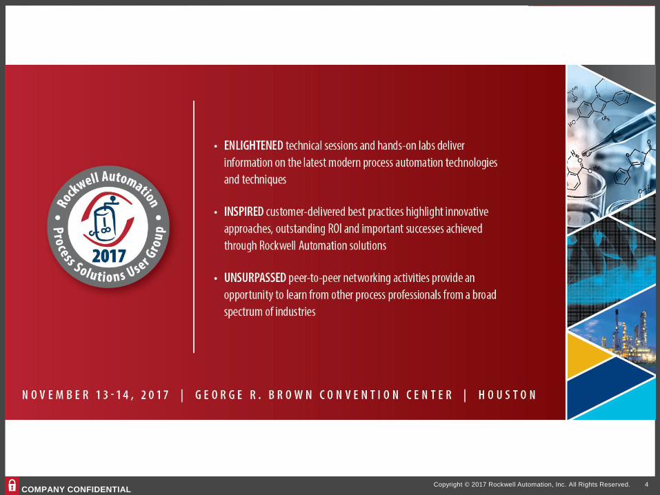
COMPANY CONFIDENTIALCopyright © 2017 Rockwell Automation, Inc. All Rights Reserved. 4
Kendall
Connection
Live

Agenda
1. Permanent Magnet AC Motor (PMAC) Technology
2. Characteristics of PMAC motors
3. Drive considerations
4. Tools and Resources
5. SyMAX product line
6. Q&A
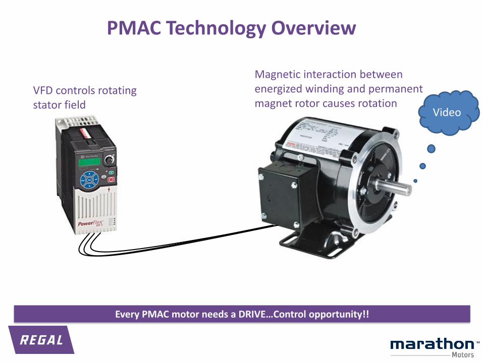
PMAC Technology Overview
VFD controls rotating stator field
Magnetic interaction between energized winding and permanent magnet rotor causes rotation
Every PMAC motor needs a DRIVE…Control opportunity!!
Video

Motor Technologies
DC Motor AC Motor
PM DC Wound
SeriesShunt
Compound
Asynchronous
Synchronous (Conventional)
Single Phase Polyphase
PMAC*
Synchronous Reluctance
Line Start PM
Stepper
Universal Motor
Servo
Servo
Shaded poleSplit phase
PSCCapacitor startCapacitor run Wound rotor
Squirrel cage
Synchronous
Switched Reluctance
*Synonymous terms:PMAC = Permanent Magnet ACPMSM = Permanent Magnet Synchronous MotorBLAC = Brush Less ACECM or EC motor = Electronically Commutated Motor
Many names for the same basic motor technology
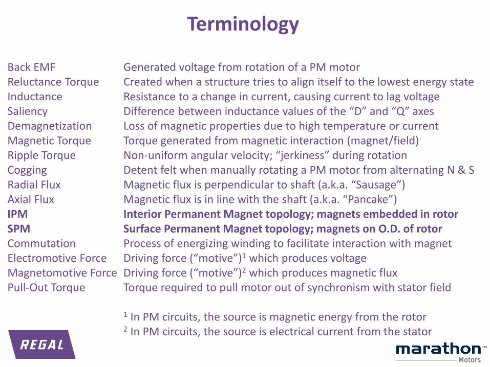
Back EMFReluctance TorqueInductanceSaliencyDemagnetizationMagnetic TorqueRipple TorqueCoggingRadial FluxAxial FluxIPMSPMCommutationElectromotive ForceMagnetomotive ForcePull-Out Torque
Generated voltage from rotation of a PM motorCreated when a structure tries to align itself to the lowest energy stateResistance to a change in current, causing current to lag voltageDifference between inductance values of the “D” and “Q” axesLoss of magnetic properties due to high temperature or currentTorque generated from magnetic interaction (magnet/field)Non-uniform angular velocity; “jerkiness” during rotationDetent felt when manually rotating a PM motor from alternating N & SMagnetic flux is perpendicular to shaft (a.k.a. “Sausage”)Magnetic flux is in line with the shaft (a.k.a. “Pancake”)Interior Permanent Magnet topology; magnets embedded in rotorSurface Permanent Magnet topology; magnets on O.D. of rotorProcess of energizing winding to facilitate interaction with magnetDriving force (“motive”)1 which produces voltageDriving force (“motive”)2 which produces magnetic fluxTorque required to pull motor out of synchronism with stator field
1 In PM circuits, the source is magnetic energy from the rotor2 In PM circuits, the source is electrical current from the stator
Terminology
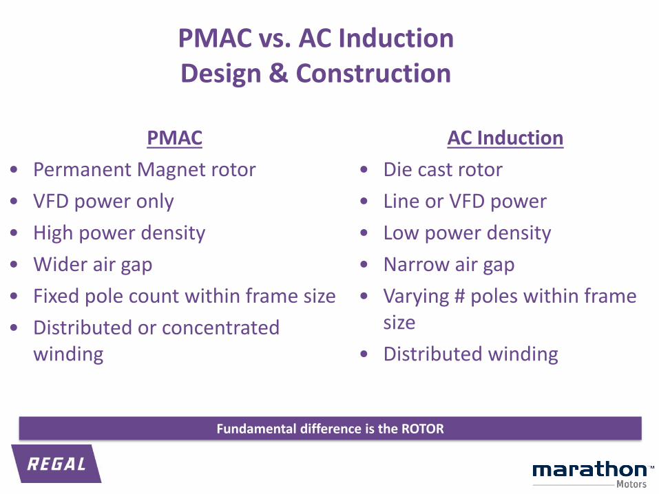
PMAC vs. AC InductionDesign & Construction
AC Induction
• Die cast rotor
• Line or VFD power
• Low power density
• Narrow air gap
• Varying # poles within frame size
• Distributed winding
PMAC
• Permanent Magnet rotor
• VFD power only
• High power density
• Wider air gap
• Fixed pole count within frame size
• Distributed or concentrated winding
Fundamental difference is the ROTOR
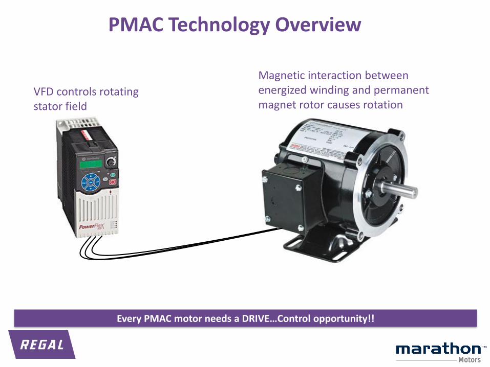
PMAC Technology Overview
VFD controls rotating stator field
Magnetic interaction between energized winding and permanent magnet rotor causes rotation
Every PMAC motor needs a DRIVE…Control opportunity!!
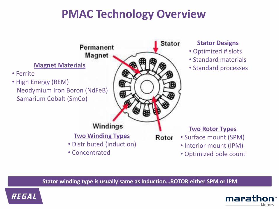
PMAC Technology Overview
Two Winding Types• Distributed (induction)• Concentrated
Magnet Materials• Ferrite• High Energy (REM)
Neodymium Iron Boron (NdFeB)Samarium Cobalt (SmCo)
Stator Designs• Optimized # slots• Standard materials• Standard processes
Two Rotor Types• Surface mount (SPM)• Interior mount (IPM)• Optimized pole count
Stator winding type is usually same as Induction…ROTOR either SPM or IPM
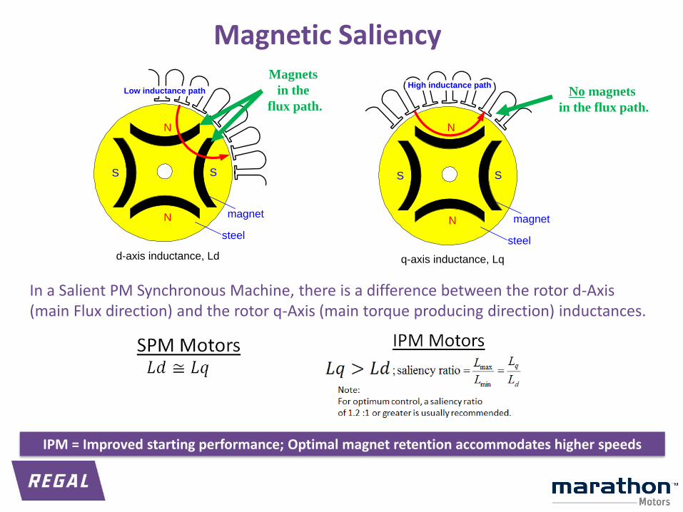
Magnetic Saliency
d-axis inductance, Ld
N
SS
N magnet
steel
Low inductance path
q-axis inductance, Lq
N
SS
N magnet
steel
High inductance pathNo magnets
in the flux path.
Magnets
in the
flux path.
In a Salient PM Synchronous Machine, there is a difference between the rotor d-Axis (main Flux direction) and the rotor q-Axis (main torque producing direction) inductances.
IPM = Improved starting performance; Optimal magnet retention accommodates higher speeds
Agenda
1. Permanent Magnet AC Motor (PMAC) Technology
2. Characteristics of PMAC motors
3. Drive considerations
4. Tools and Resources
5. SyMAX product line
6. Q&A
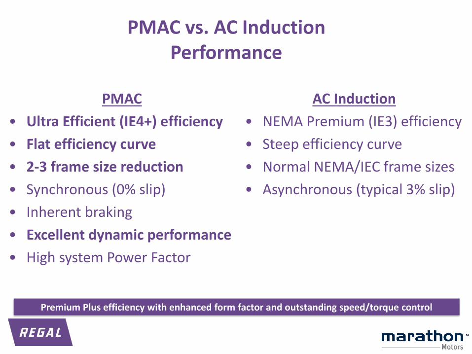
PMAC vs. AC InductionPerformance
AC Induction
• NEMA Premium (IE3) efficiency
• Steep efficiency curve
• Normal NEMA/IEC frame sizes
• Asynchronous (typical 3% slip)
PMAC
• Ultra Efficient (IE4+) efficiency
• Flat efficiency curve
• 2-3 frame size reduction
• Synchronous (0% slip)
• Inherent braking
• Excellent dynamic performance
• High system Power Factor
Premium Plus efficiency with enhanced form factor and outstanding speed/torque control

Efficiency: PMAC vs. NEMA Premium
0.70
0.75
0.80
0.85
0.90
0.95
0 200 400 600 800 1000 1200 1400 1600 1800 2000
Eff
icie
ncy
Speed (RPM)
Variable Speed Constant Torque Motor PerformanceEfficiency vs Speed
5 HP, 184T SyMAX PMAC vs NEMA Premium Induction
PM Motor Eff
Ind Motor Eff
91.7% (338 watts loss)
89.5% (438 watts loss)
900
90.6% (387 watts loss)
84.6% (679 watts loss) 23% improvement
43% improvement
20-30% more efficient at full load; 40-50% more efficient at reduced load
Calculator is located on the SyMAX Motors web site.
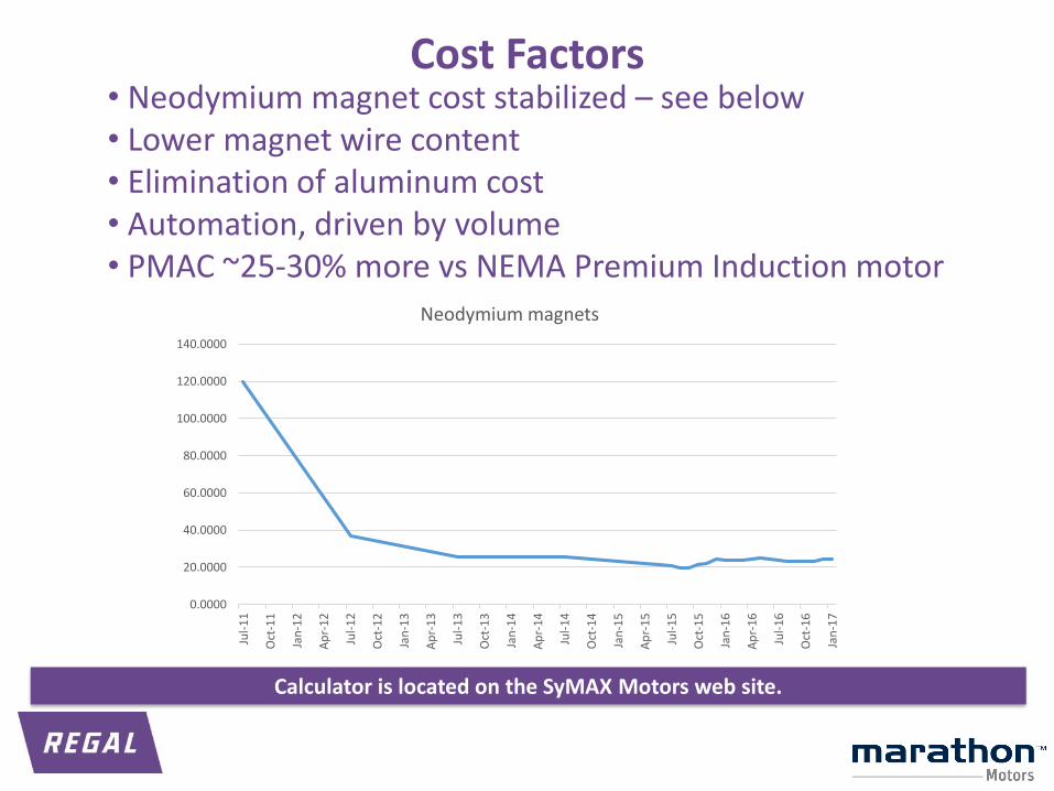
• Neodymium magnet cost stabilized – see below• Lower magnet wire content • Elimination of aluminum cost• Automation, driven by volume• PMAC ~25-30% more vs NEMA Premium Induction motor
0.0000
20.0000
40.0000
60.0000
80.0000
100.0000
120.0000
140.0000
Jul-
11
Oct
-11
Jan
-12
Ap
r-1
2
Jul-
12
Oct
-12
Jan
-13
Ap
r-1
3
Jul-
13
Oct
-13
Jan
-14
Ap
r-1
4
Jul-
14
Oct
-14
Jan
-15
Ap
r-1
5
Jul-
15
Oct
-15
Jan
-16
Ap
r-1
6
Jul-
16
Oct
-16
Jan
-17
Neodymium magnets
Cost Factors
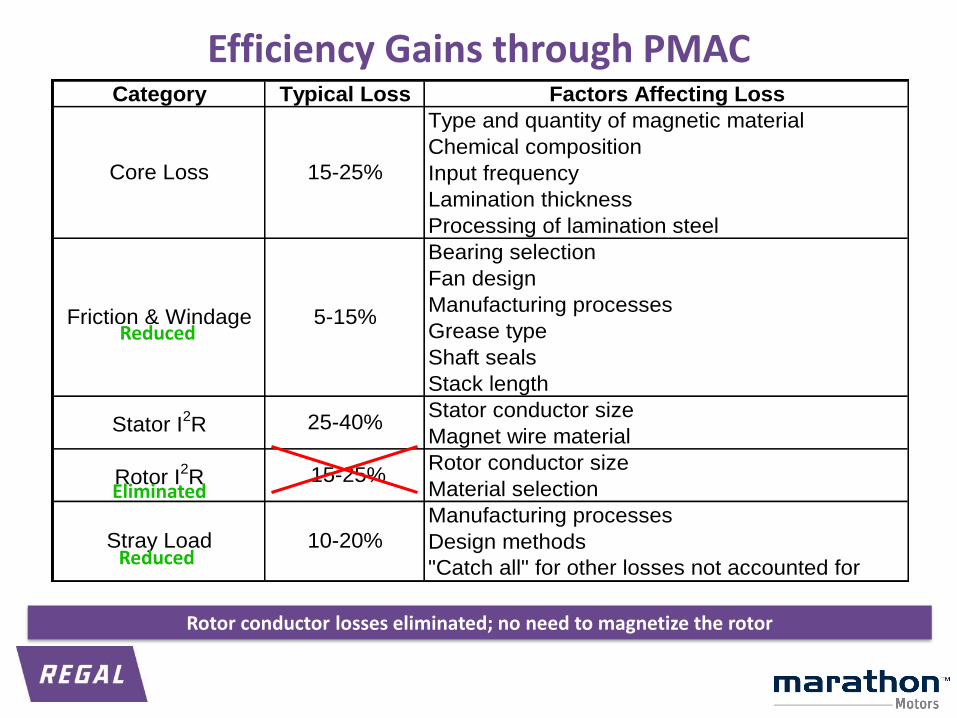
Efficiency Gains through PMACCategory Typical Loss Factors Affecting Loss
Type and quantity of magnetic material
Chemical composition
Input frequency
Lamination thickness
Processing of lamination steel
Bearing selection
Fan design
Manufacturing processes
Grease type
Shaft seals
Stack length
Stator conductor size
Magnet wire material
Rotor conductor size
Material selection
Manufacturing processes
Design methods
"Catch all" for other losses not accounted for
Stray Load
15-25%
5-15%
25-40%
15-25%
10-20%
Core Loss
Friction & Windage
Stator I2R
Rotor I2R
Eliminated
Reduced
Reduced
Rotor conductor losses eliminated; no need to magnetize the rotor
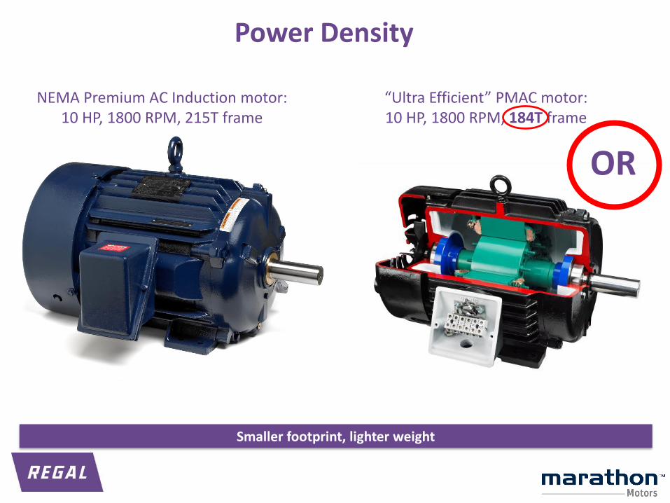
Power Density
NEMA Premium AC Induction motor:10 HP, 1800 RPM, 215T frame
“Ultra Efficient” PMAC motor:10 HP, 1800 RPM, 184T frame
OR
Smaller footprint, lighter weight
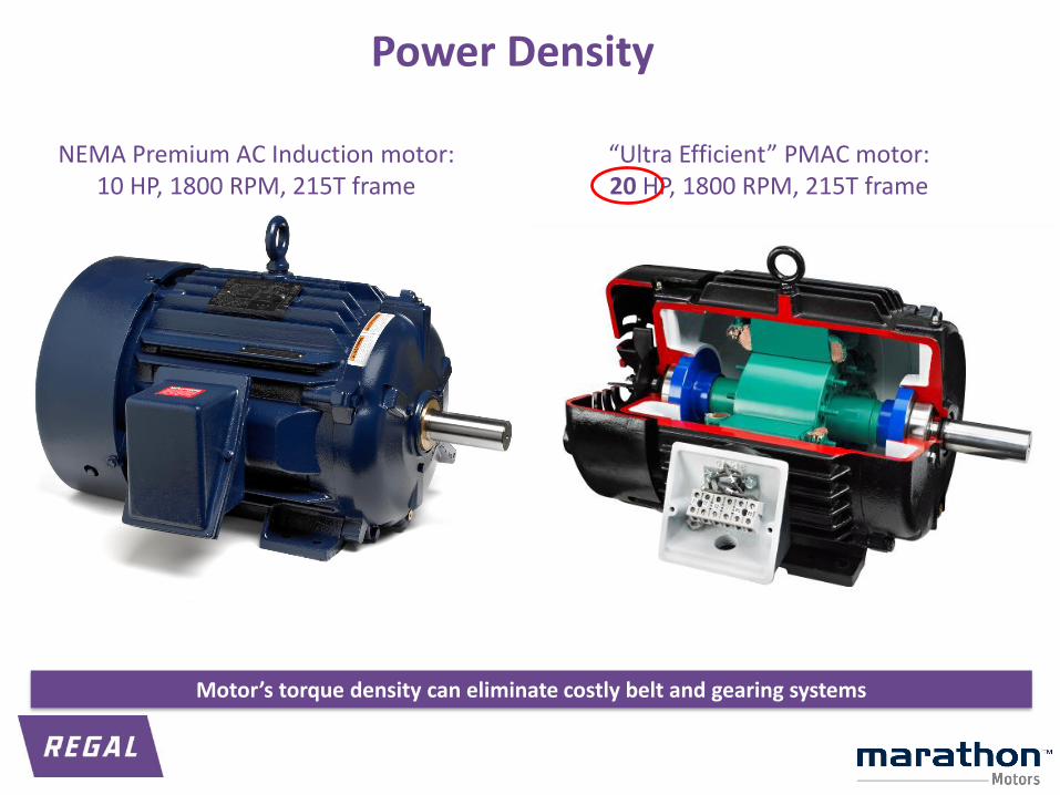
“Ultra Efficient” PMAC motor:20 HP, 1800 RPM, 215T frame
Power Density
NEMA Premium AC Induction motor:10 HP, 1800 RPM, 215T frame
Motor’s torque density can eliminate costly belt and gearing systems
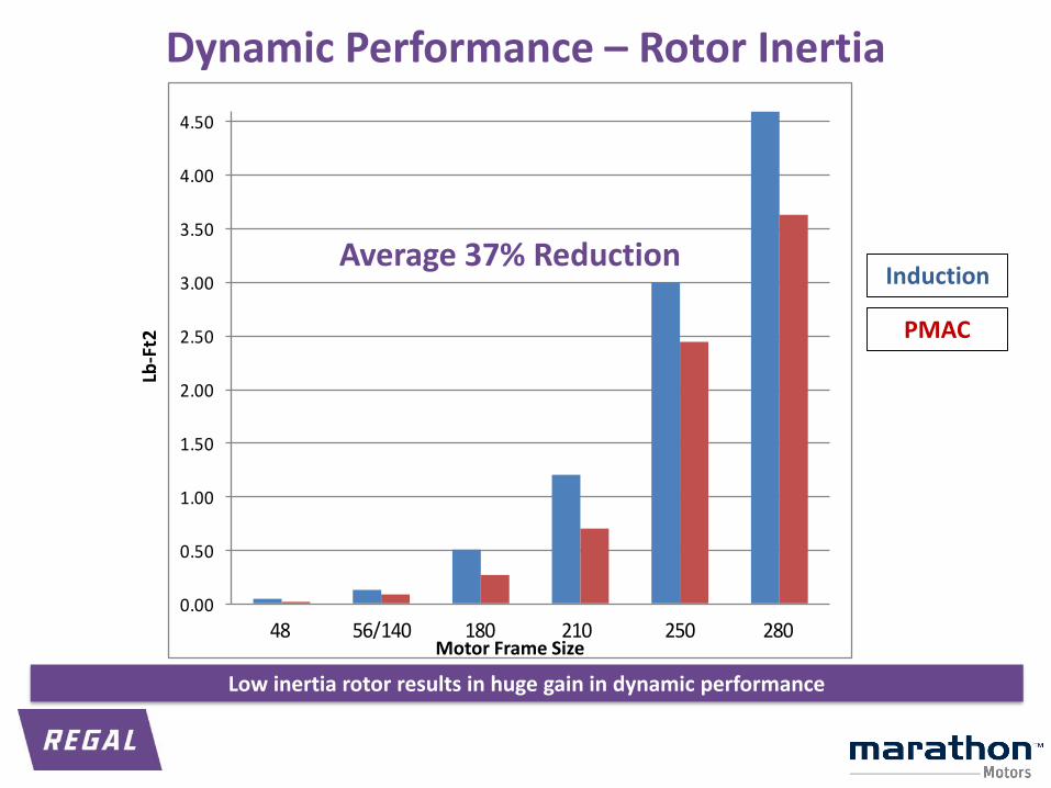
Dynamic Performance – Rotor Inertia
0.00
0.50
1.00
1.50
2.00
2.50
3.00
3.50
4.00
4.50
48 56/140 180 210 250 280
Lb-F
t2
Motor Frame Size
Induction
PMAC
Average 37% Reduction
Low inertia rotor results in huge gain in dynamic performance
Agenda
1. Permanent Magnet AC Motor (PMAC) Technology
2. Characteristics of PMAC motors
3. Drive considerations
4. Tools and Resources
5. SyMAX product line
6. Q&A
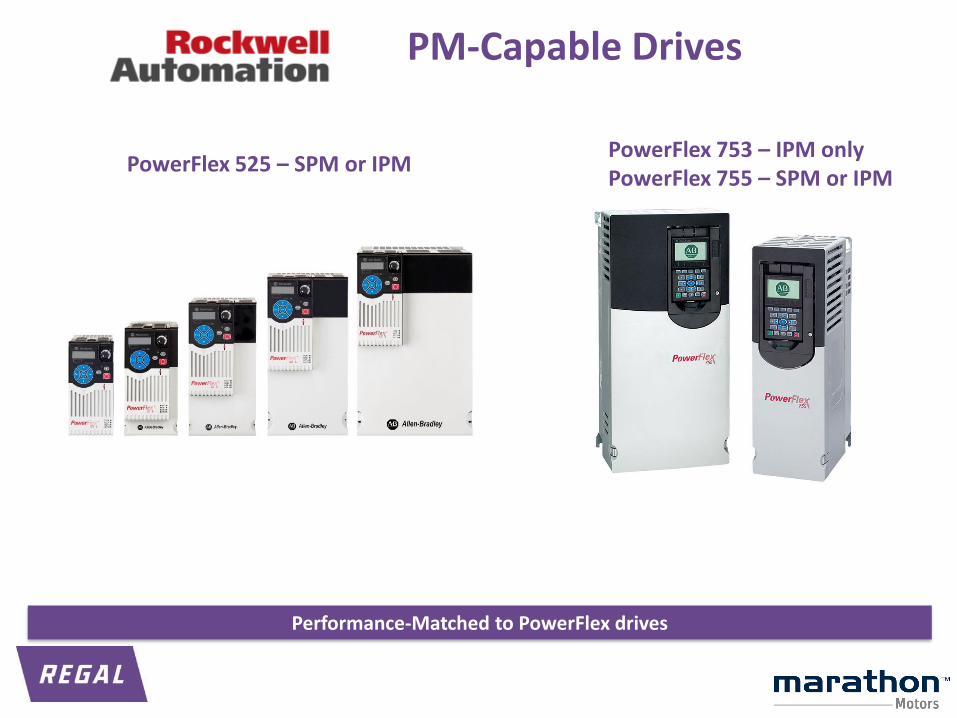
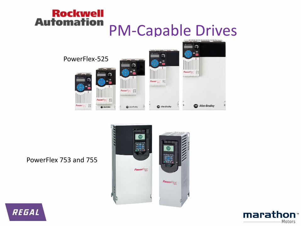
PM-Capable Drives
PowerFlex 753 – IPM onlyPowerFlex 755 – SPM or IPM
PowerFlex 525 – SPM or IPM
Performance-Matched to PowerFlex drives
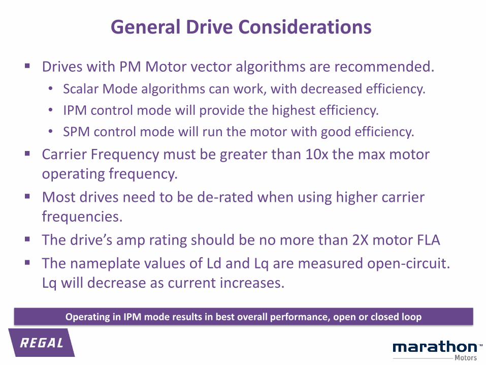
General Drive Considerations
▪ Drives with PM Motor vector algorithms are recommended.
• Scalar Mode algorithms can work, with decreased efficiency.
• IPM control mode will provide the highest efficiency.
• SPM control mode will run the motor with good efficiency.
▪ Carrier Frequency must be greater than 10x the max motor operating frequency.
▪ Most drives need to be de-rated when using higher carrier frequencies.
▪ The drive’s amp rating should be no more than 2X motor FLA
▪ The nameplate values of Ld and Lq are measured open-circuit. Lq will decrease as current increases.
Operating in IPM mode results in best overall performance, open or closed loop
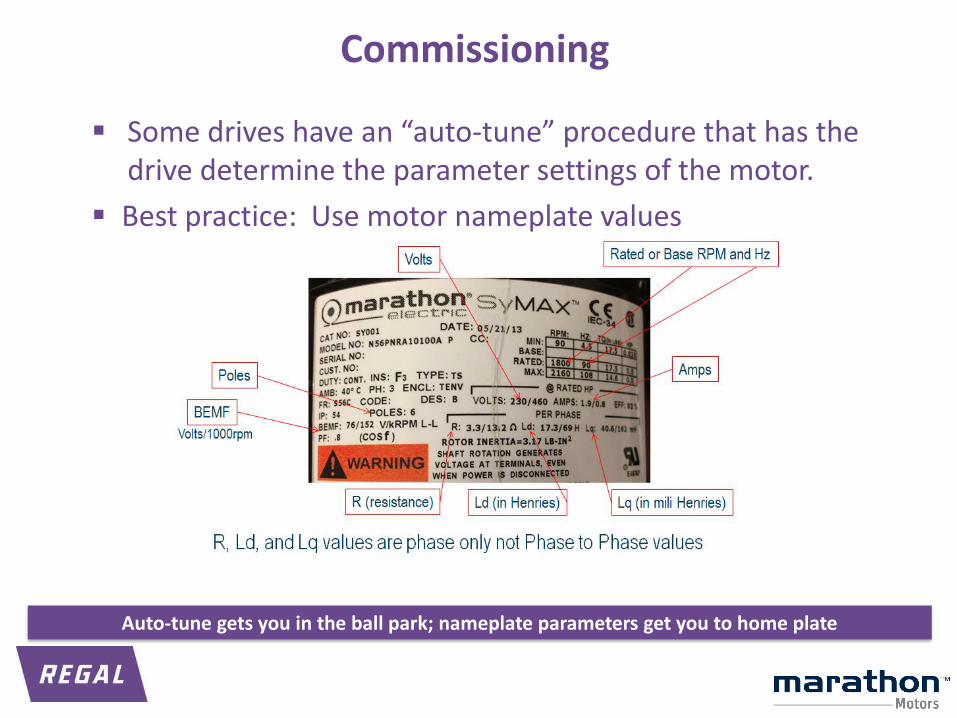
▪ Some drives have an “auto-tune” procedure that has the drive determine the parameter settings of the motor.
▪ Best practice: Use motor nameplate values
Commissioning
Auto-tune gets you in the ball park; nameplate parameters get you to home plate

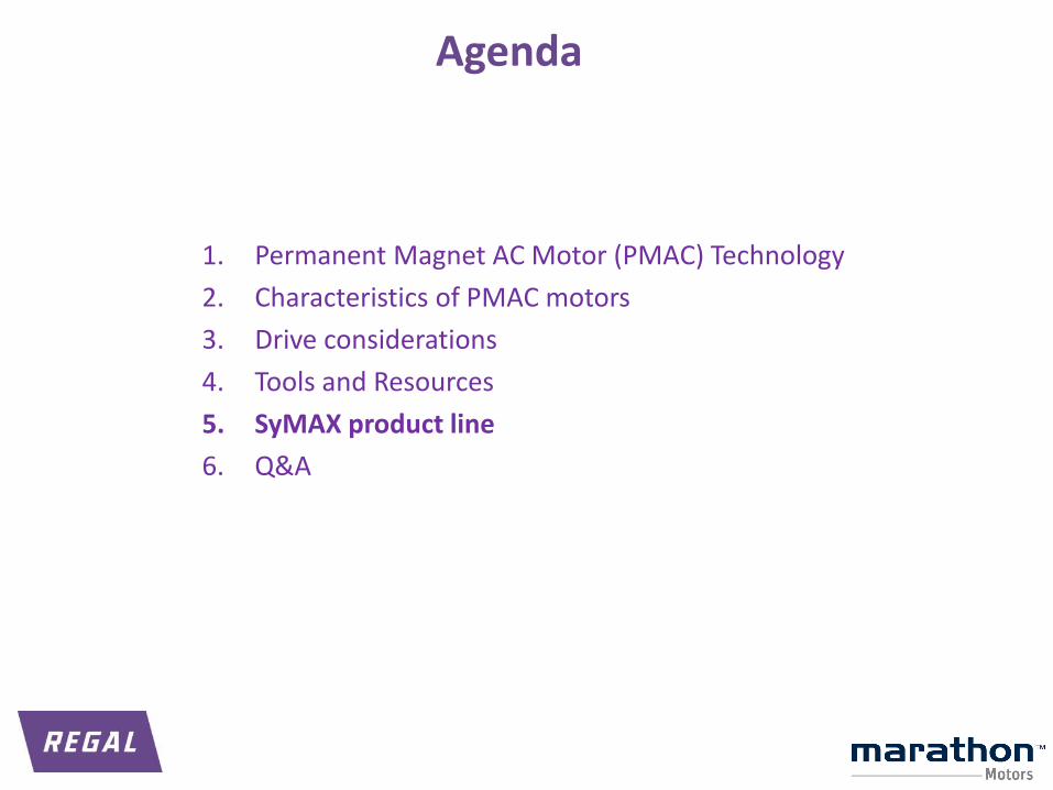
Agenda
1. Permanent Magnet AC Motor (PMAC) Technology
2. Characteristics of PMAC motors
3. Drive considerations
4. Tools and Resources
5. SyMAX product line
6. Q&A
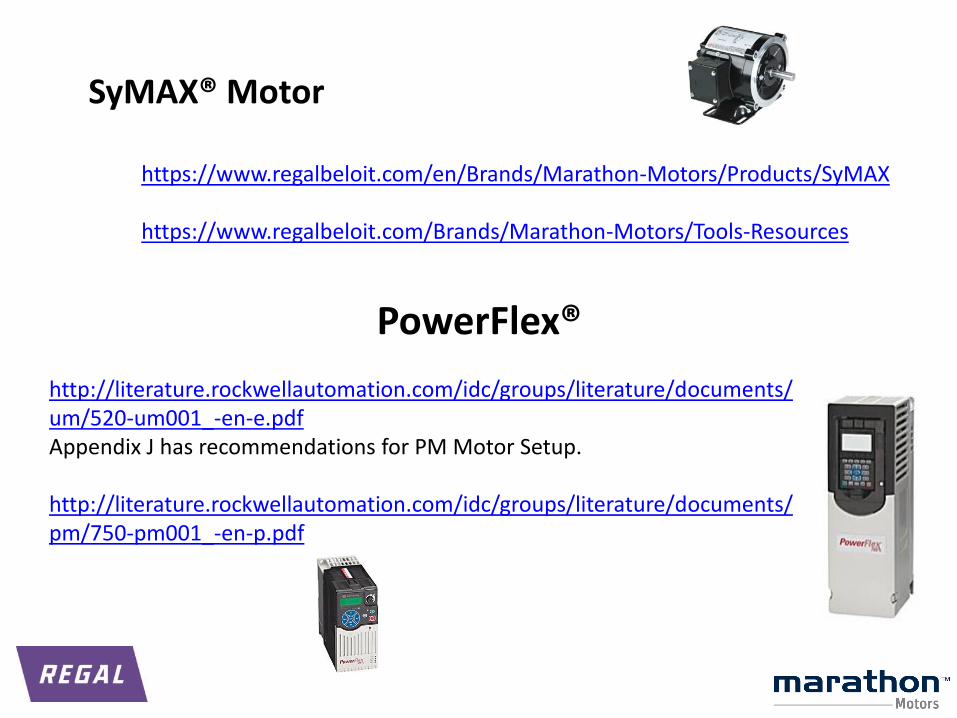
https://www.regalbeloit.com/en/Brands/Marathon-Motors/Products/SyMAX
https://www.regalbeloit.com/Brands/Marathon-Motors/Tools-Resources
SyMAX® Motor
http://literature.rockwellautomation.com/idc/groups/literature/documents/um/520-um001_-en-e.pdfAppendix J has recommendations for PM Motor Setup.
http://literature.rockwellautomation.com/idc/groups/literature/documents/pm/750-pm001_-en-p.pdf
PowerFlex®
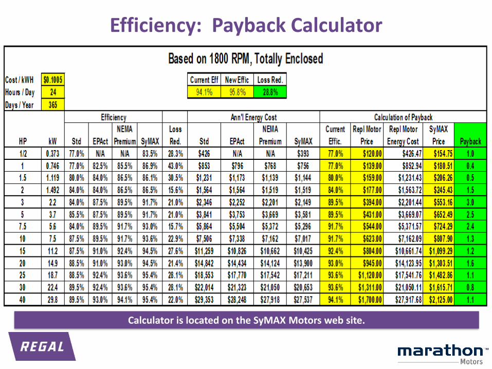
Efficiency: Payback Calculator
Calculator is located on the SyMAX Motors web site.
1. Permanent Magnet AC Motor (PMAC) Technology
2. Characteristics of PMAC motors
3. Drive considerations
4. Tools and Resources
5. SyMAX product line
6. Q&A
p 29
Agenda
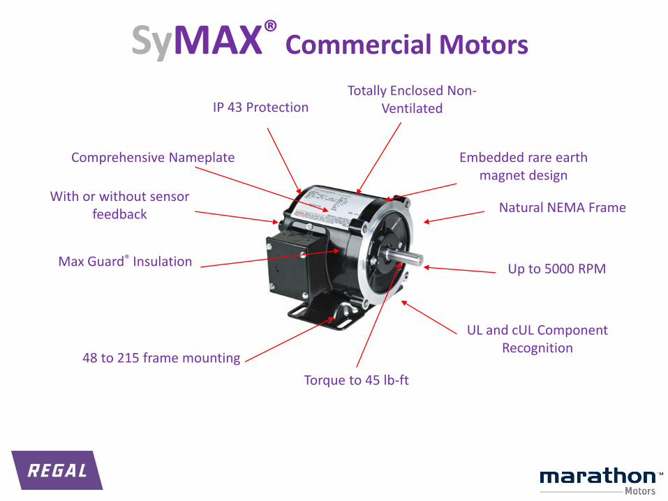
IP 43 Protection
Max Guard® Insulation
Natural NEMA Frame
Comprehensive Nameplate
Up to 5000 RPM
Totally Enclosed Non-Ventilated
With or without sensor feedback
48 to 215 frame mounting
Embedded rare earth magnet design
UL and cUL Component Recognition
Torque to 45 lb-ft
SyMAX® Commercial Motors

V-Ring “Forsheda” shaft seal (optional)
Natural NEMA Frame
IP 54 Protection(IP55 or 56 optional) Comprehensive Nameplate
Cast Iron Severe Duty Construction
Ultra Efficient™
IE4 levels,
Higher than NEMA Premium
Max Guard® Insulation
Terminal Block
(optional)
Cast Iron Bearing Caps (ea end)
Precision Balanced Rotor
Grounding Provisions on Frame/Foot
Epoxy interior & exterior paint
Encoder provisions
(optional)
TEFC – Standard
TENV or TEBC (optional)
SyMAX® Industrial Motors
p 32
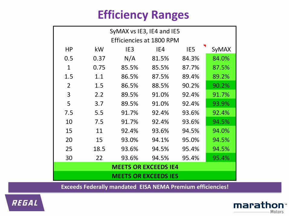
HP kW IE3 IE4 IE5 SyMAX
0.5 0.37 N/A 81.5% 84.3% 84.0%
1 0.75 85.5% 85.5% 87.7% 87.5%
1.5 1.1 86.5% 87.5% 89.4% 89.2%
2 1.5 86.5% 88.5% 90.2% 90.2%
3 2.2 89.5% 91.0% 92.4% 91.7%
5 3.7 89.5% 91.0% 92.4% 93.9%
7.5 5.5 91.7% 92.4% 93.6% 92.4%
10 7.5 91.7% 92.4% 93.6% 94.5%
15 11 92.4% 93.6% 94.5% 94.0%
20 15 93.0% 94.1% 95.0% 94.5%
25 18.5 93.6% 94.5% 95.4% 94.5%
30 22 93.6% 94.5% 95.4% 95.4%
SyMAX vs IE3, IE4 and IE5
Efficiencies at 1800 RPM
MEETS OR EXCEEDS IE5
MEETS OR EXCEEDS IE4
Efficiency Ranges
Exceeds Federally mandated EISA NEMA Premium efficiencies!
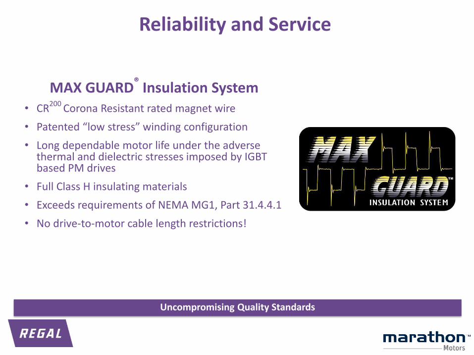
Reliability and Service
MAX GUARD® Insulation System• CR200 Corona Resistant rated magnet wire
• Patented “low stress” winding configuration
• Long dependable motor life under the adverse thermal and dielectric stresses imposed by IGBT based PM drives
• Full Class H insulating materials
• Exceeds requirements of NEMA MG1, Part 31.4.4.1
• No drive-to-motor cable length restrictions!
Uncompromising Quality Standards
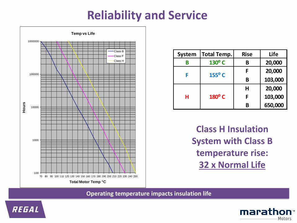
100
1000
10000
100000
1000000
70 80 90 100 110 120 130 140 150 160 170 180 190 200 210 220 230 240 250
Ho
urs
Total Motor Temp °C
Temp vs Life
Class B
Class F
Class H
Class H Insulation System with Class B temperature rise:32 x Normal Life
System Total Temp. Rise Life
B 130⁰ C B 20,000
F 20,000
B 103,000
H 20,000
F 103,000
B 650,000
H
155⁰ C
180⁰ C
F
Reliability and Service
Operating temperature impacts insulation life
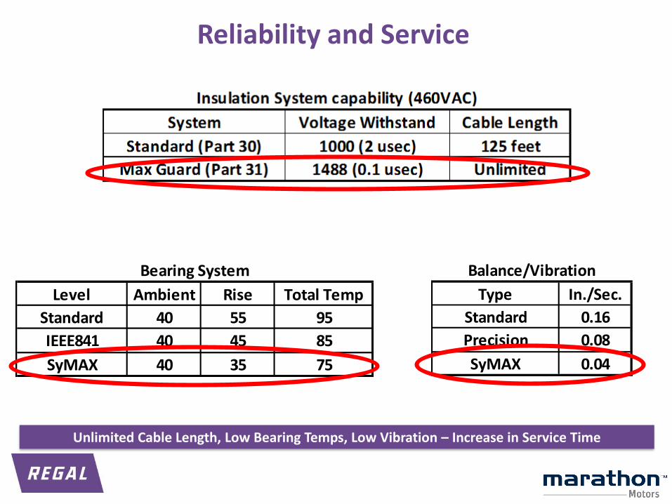
Level Ambient Rise Total Temp
Standard 40 55 95
IEEE841 40 45 85
SyMAX 40 35 75
Bearing System
Type In./Sec.
Standard 0.16
Precision 0.08
SyMAX 0.04
Balance/Vibration
Reliability and Service
Unlimited Cable Length, Low Bearing Temps, Low Vibration – Increase in Service Time
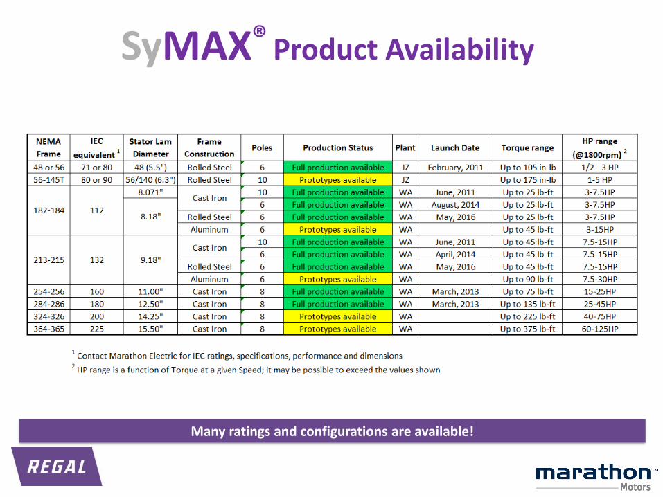
SyMAX® Product Availability
Many ratings and configurations are available!
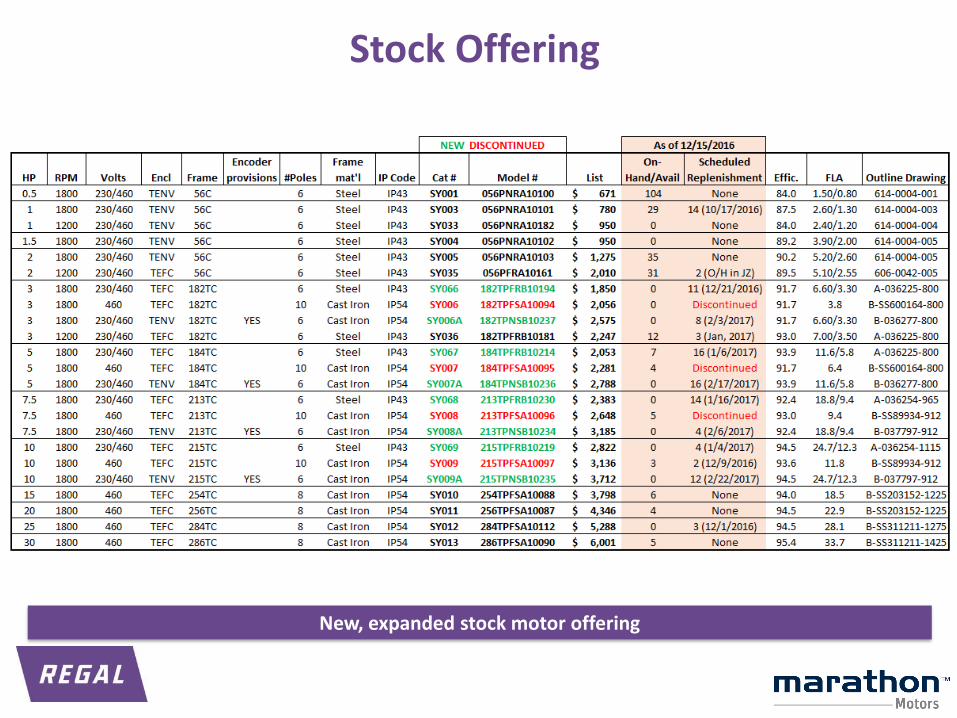
New, expanded stock motor offering
Stock Offering
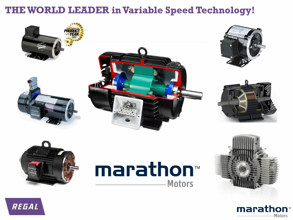
THE WORLD LEADER in Variable Speed Technology!
PM-Capable Drives
PowerFlex-525
PowerFlex 753 and 755
General Drive Considerations
▪ Drives with PM Motor vector algorithms are recommended (PF-755 uses Vector).
▪ Some drives with Scalar Mode algorithms can work, with decreased efficiency. (PF-525 uses Scalar)
▪ IPM control mode (that uses both Ld and Lq values) will provide the highest efficiency.
▪ SPM control mode will run the motor with reasonable efficiency.
▪ Carrier Frequency must be greater than 10x the max motor operating frequency.
▪ Most drives need to be de-rated when using higher carrier frequencies.
▪ The drive’s amp rating should be no more than 2X motor FLA
▪ In order to optimize efficiency of the motor, sometimes experimentation with drive settings is needed.
▪ “Tricking” the drive with incorrect values may or may not work well, depending on the drive and the load you’re trying to run. “Tricking” the drive should be avoided.
▪ Some drives have an “auto-tune” procedure that has the drive determine the parameter settings of the motor.
▪ These values are not always accurate and should be checked before running the motor.
General Drive Considerations
VFD Drive and PMAC motor
Drive settings explained &Demonstrated
PF-525 with PMAC Motor Start-up Guide
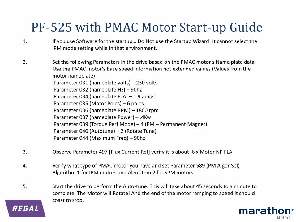
1. If you use Software for the startup… Do Not use the Startup Wizard! It cannot select thePM mode setting while in that environment.
2. Set the following Parameters in the drive based on the PMAC motor’s Name plate data.Use the PMAC motor’s Base speed information not extended values (Values from themotor nameplate)Parameter 031 (nameplate volts) – 230 voltsParameter 032 (nameplate Hz) – 90hzParameter 034 (nameplate FLA) – 1.9 ampsParameter 035 (Motor Poles) – 6 polesParameter 036 (nameplate RPM) – 1800 rpmParameter 037 (nameplate Power) – .4KwParameter 039 (Torque Perf Mode) – 4 (PM – Permanent Magnet)Parameter 040 (Autotune) – 2 (Rotate Tune)Parameter 044 (Maximum Freq) – 90hz
3. Observe Parameter 497 [Flux Current Ref] verify it is about .6 x Motor NP FLA
4. Verify what type of PMAC motor you have and set Parameter 589 (PM Algor Sel)Algorithm 1 for IPM motors and Algorithm 2 for SPM motors.
5. Start the drive to perform the Auto-tune. This will take about 45 seconds to a minute to complete. The Motor will Rotate! And the end of the motor ramping to speed it should coast to stop.
PF-525 with PMAC Motor Start-up Guide
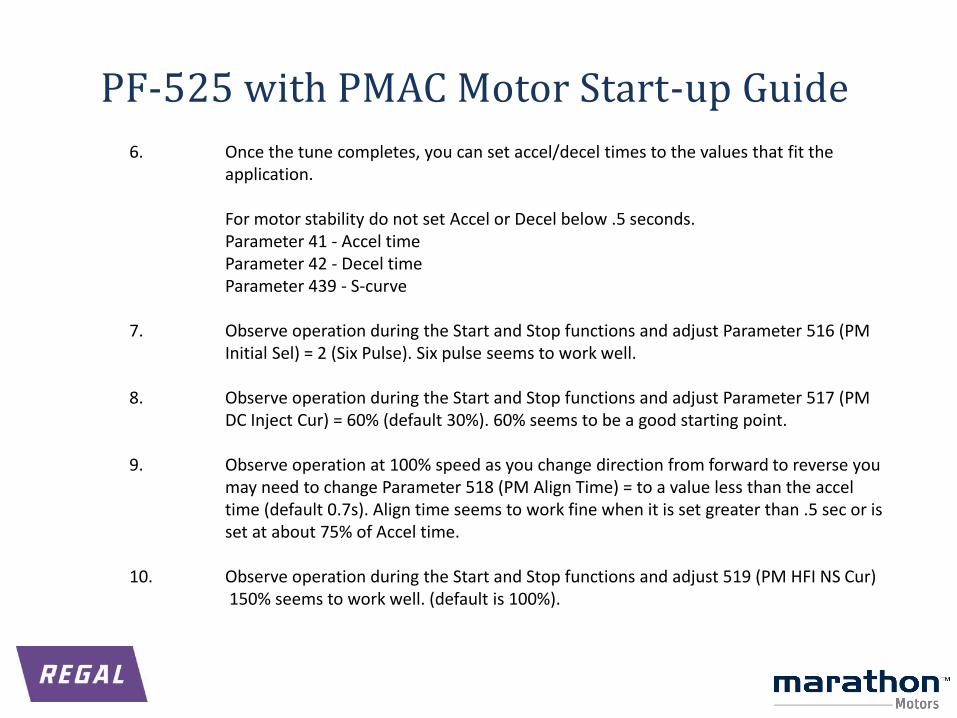
6. Once the tune completes, you can set accel/decel times to the values that fit the application.
For motor stability do not set Accel or Decel below .5 seconds. Parameter 41 - Accel timeParameter 42 - Decel timeParameter 439 - S-curve
7. Observe operation during the Start and Stop functions and adjust Parameter 516 (PM Initial Sel) = 2 (Six Pulse). Six pulse seems to work well.
8. Observe operation during the Start and Stop functions and adjust Parameter 517 (PM DC Inject Cur) = 60% (default 30%). 60% seems to be a good starting point.
9. Observe operation at 100% speed as you change direction from forward to reverse you may need to change Parameter 518 (PM Align Time) = to a value less than the accel time (default 0.7s). Align time seems to work fine when it is set greater than .5 sec or is set at about 75% of Accel time.
10. Observe operation during the Start and Stop functions and adjust 519 (PM HFI NS Cur) 150% seems to work well. (default is 100%).
PF-525 with PMAC Motor Start-up Guide
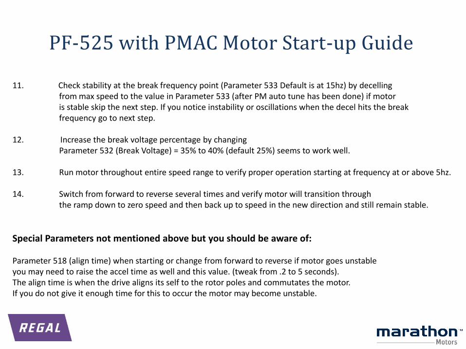
11. Check stability at the break frequency point (Parameter 533 Default is at 15hz) by decellingfrom max speed to the value in Parameter 533 (after PM auto tune has been done) if motor is stable skip the next step. If you notice instability or oscillations when the decel hits the break frequency go to next step.
12. Increase the break voltage percentage by changing Parameter 532 (Break Voltage) = 35% to 40% (default 25%) seems to work well.
13. Run motor throughout entire speed range to verify proper operation starting at frequency at or above 5hz.
14. Switch from forward to reverse several times and verify motor will transition through the ramp down to zero speed and then back up to speed in the new direction and still remain stable.
Special Parameters not mentioned above but you should be aware of:
Parameter 518 (align time) when starting or change from forward to reverse if motor goes unstable you may need to raise the accel time as well and this value. (tweak from .2 to 5 seconds). The align time is when the drive aligns its self to the rotor poles and commutates the motor. If you do not give it enough time for this to occur the motor may become unstable.
PF-525 with PMAC Motor Start-up Guide
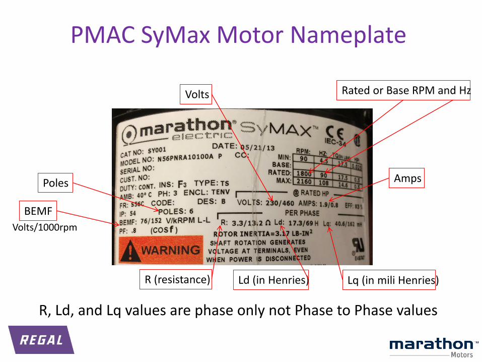
BEMF
Volts/1000rpm
Poles
Volts
Amps
Rated or Base RPM and Hz
R (resistance) Ld (in Henries) Lq (in mili Henries)
PMAC SyMax Motor Nameplate
R, Ld, and Lq values are phase only not Phase to Phase values