Embed Size (px)
Citation preview

MAKING MODERN LIVING POSSIBLE
Technical Information
Foot PedalKEP Uni-directional and Bi-directional
powersolutions.danfoss.com
Revision history Table of revisions
Date Changed Rev
July 2015 Converted to Danfoss layout EA
November 2011 Corrected Option 1 and 2 drawing DA
October 2011 Added interchangeable part number reference to Unidirectional Model Type table CB
September 2010 Major update CA
January 2010 Major update BA
January 2009 Initial release AB
Technical Information KEP Foot Pedal
2 11044978 • Rev EA • July 2015
OverviewDescription..........................................................................................................................................................................................4Features................................................................................................................................................................................................4
Uni-directional model type..................................................................................................................................................... 4Bi-directional model type.........................................................................................................................................................4
Operation............................................................................................................................................................................................ 4Uni-directional model type .................................................................................................................................................... 4Bi-directional model type.........................................................................................................................................................5
Ordering information......................................................................................................................................................................5Uni-directional model type..................................................................................................................................................... 5Bi-directional model type.........................................................................................................................................................5
Optional connector...............................................................................................................................................................6
Technical dataUni-directional model type...........................................................................................................................................................7Bi-directional model type..............................................................................................................................................................8
DimensionsUni-directional model type...........................................................................................................................................................9Bi-directional model type............................................................................................................................................................10
Output characteristicsUni-directional model type........................................................................................................................................................ 11Bi-directional model type............................................................................................................................................................11
Electrical connectionsUni-directional model type ....................................................................................................................................................... 13Bi-directional model type............................................................................................................................................................14Wiring harness.................................................................................................................................................................................14
Connector A: Metri-Pack connector...................................................................................................................................15Connector B: Weather Pack connector (shroud)........................................................................................................... 15Connector C: Weather Pack connector (tower)............................................................................................................. 15
Schematics of a foot pedal connected to a PLUS+1® module....................................................................................... 16Example, part 1..........................................................................................................................................................................16Example, part 2..........................................................................................................................................................................17PLUS+1® module pin connections example................................................................................................................... 18
Technical Information KEP Foot Pedal
Contents
11044978 • Rev EA • July 2015 3

Description
The electronic foot pedal is used to drive vehicles equipped with hydrostatic transmissions and/orelectronically-controlled engines. It provides an electrical signal to the engine’s electronics proportionalto the degree of pedal actuation. The electronic foot pedal features a sensor specifically designed forheavy vehicle applications.
Danfoss offers two types of foot pedals: Uni-directional and Bi-directional. The uni-directional uses apotentiometer sensor and was the first electronic foot pedal introduced by Danfoss in 1993. The new bi-directional type uses Hall effect sensors. Both types of foot pedals are PLUS+1® Compliant.
Features
Uni-directional model type
• Potentiometer sensor
• Meets or exceeds FMVSS-124 requirements
• Low pivot point eliminates need for external heel rest
• Controls acceleration and deceleration smoothly
• Potentiometer mounting location minimizes mounting space requirements and reduces vulnerabilityto dirt, water, and foreign contaminants
• 3 pin Weather Pack compatible connector
Bi-directional model type
• Hall effect sensors
• 14 ± 2° angular rotation, fore and aft
• FMVSS 124 and 302 compliant
• Dual ratiometric Automatic Protection Switching (APS) output
‒ This feature provides redundancy
• Independent, isolated APS circuits
• Protected against electrical misconnection
• 6 pin Metri-Pack 150 Series connector directly on the sensor
• Two 3 pin Weather Pack compatible connector
‒ These connectors are used with the recommended cable (reference Schematics of a foot pedalconnected to a PLUS+1 module on page 16)
• Non contact sensor
• Black coated steel base and treadle
• Chromate conversion module components
Operation
Uni-directional model type
The electronic foot pedal accepts a typical supply voltage of 5 Vdc and varies the output from 10% to90% of supply through the pedal’s rated angle. Three standard accelerator position sensor models areavailable for vehicle toeboard angles ranging from 0° to 25°. Custom mounting, termination, andelectrical characteristics are available upon factory request.
Technical Information KEP Foot Pedal
Overview
4 11044978 • Rev EA • July 2015
Bi-directional model type
The electronic foot pedal contains two independent non-contact transducers (Hall elements). Thetransducers are designed to operate at 5 Vdc.
The signal range for each transducer can be configured to match a machine’s requirements. Currently,two different signal options are offered, reference Technical data, Bi-directional model type on page 8.
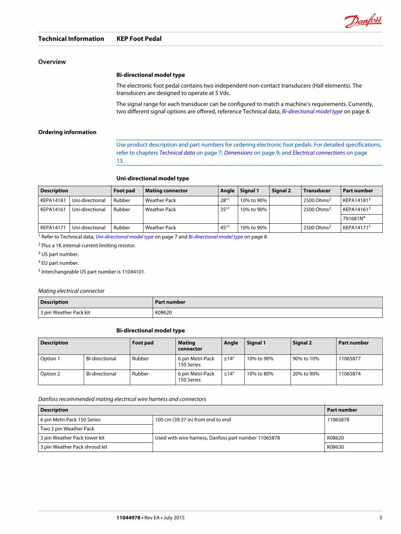
Ordering information
Use product description and part numbers for ordering electronic foot pedals. For detailed specifications,refer to chapters Technical data on page 7; Dimensions on page 9; and Electrical connections on page13.
Uni-directional model type
Description Foot pad Mating connector Angle Signal 1 Signal 2 Transducer Part number
KEPA14181 Uni-directional Rubber Weather Pack 28°1 10% to 90% 2500 Ohms2 KEPA141813
KEPA14161 Uni-directional Rubber Weather Pack 35°1 10% to 90% 2500 Ohms2 KEPA141613
791681N4
KEPA14171 Uni-directional Rubber Weather Pack 45°1 10% to 90% 2500 Ohms2 KEPA141715
1 Refer to Technical data, Uni-directional model type on page 7 and Bi-directional model type on page 8.2 Plus a 1K internal current limiting resistor.3 US part number.4 EU part number.5 Interchangeable US part number is 11044101.
Mating electrical connector
Description Part number
3 pin Weather Pack kit K08620
Bi-directional model type
Description Foot pad Matingconnector
Angle Signal 1 Signal 2 Part number
Option 1 Bi-directional Rubber 6 pin Metri-Pack150 Series
±14° 10% to 90% 90% to 10% 11065877
Option 2 Bi-directional Rubber 6 pin Metri-Pack150 Series
±14° 10% to 80% 20% to 90% 11065874
Danfoss recommended mating electrical wire harness and connectors
Description Part number
6 pin Metri-Pack 150 Series 100 cm (39.37 in) from end to end 11065878
Two 3 pin Weather Pack
3 pin Weather Pack tower kit Used with wire harness, Danfoss part number 11065878 K08620
3 pin Weather Pack shroud kit K08630
Technical Information KEP Foot Pedal
Overview
11044978 • Rev EA • July 2015 5
Optional connector
The optional mating electrical connector for the bi-directional model type must be ordered directly froma Packard Electric (Delphi Connection Systems) supplier.
C Caution
The electrical connection may be at risk. Wiring directly to the 6 pin Metri-Pack connector, which isintegral to the sensor, may not provide the flexibility and overall integrity that can otherwise be obtainedby using the Danfoss recommended harness (Danfoss part number 11065878).
Optional mating electrical connector piece parts for bi-directional model type
Description Packard Electric part number
6 pin Metri-Pack 150 Series One Connector and Seal 12066317
Six Terminals 12013881
Technical Information KEP Foot Pedal
Overview
6 11044978 • Rev EA • July 2015
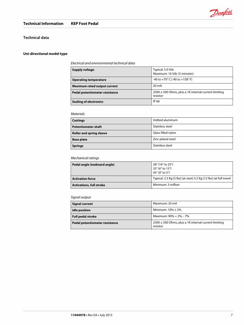
Uni-directional model type
Electrical and environmental technical data
Supply voltage Typical: 5.0 VdcMaximum: 16 Vdc (5 minutes)
Operating temperature -40 to +70° C [-40 to +158° F]
Maximum rated output current 20 mA
Pedal potentiometer resistance 2500 ± 500 Ohms, plus a 1K internal current limitingresistor
Sealing of electronics IP 66
Materials
Castings Iridited aluminum
Potentiometer shaft Stainless steel
Roller and spring sleeve Glass filled nylon
Base plate Zinc plated steel
Springs Stainless steel
Mechanical ratings
Pedal angle (toeboard angle) 28° (16° to 25°)35° (6° to 15°)45° (0° to 5°)
Activation force Typical: 2.3 Kg [5 lbs] (at start) 5.5 Kg [12 lbs] (at full travel
Activations, full stroke Minimum: 3 million
Signal output
Signal current Maximum: 20 mA
Idle position Minimum: 10% ± 2%
Full pedal stroke Maximum: 90% + 2%, - 7%
Pedal potentiometer resistance 2500 ± 500 Ohms, plus a 1K internal current limitingresistor
Technical Information KEP Foot Pedal
Technical data
11044978 • Rev EA • July 2015 7
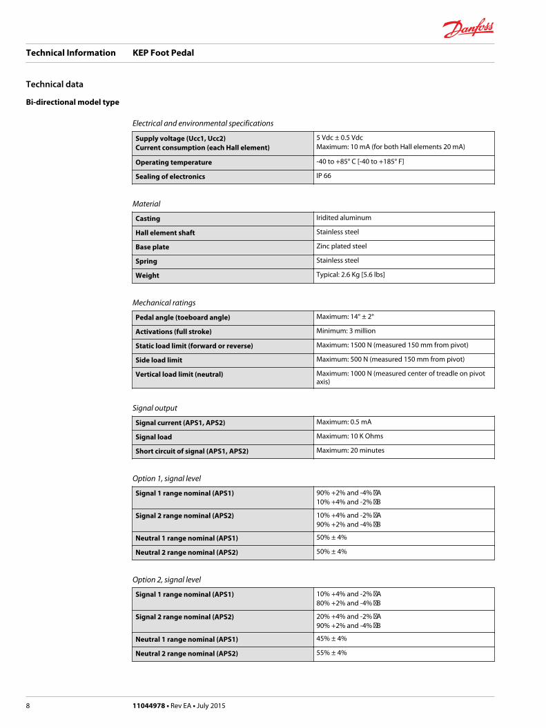
Bi-directional model type
Electrical and environmental specifications
Supply voltage (Ucc1, Ucc2)Current consumption (each Hall element)
5 Vdc ± 0.5 VdcMaximum: 10 mA (for both Hall elements 20 mA)
Operating temperature -40 to +85° C [-40 to +185° F]
Sealing of electronics IP 66
Material
Casting Iridited aluminum
Hall element shaft Stainless steel
Base plate Zinc plated steel
Spring Stainless steel
Weight Typical: 2.6 Kg [5.6 lbs]
Mechanical ratings
Pedal angle (toeboard angle) Maximum: 14° ± 2°
Activations (full stroke) Minimum: 3 million
Static load limit (forward or reverse) Maximum: 1500 N (measured 150 mm from pivot)
Side load limit Maximum: 500 N (measured 150 mm from pivot)
Vertical load limit (neutral) Maximum: 1000 N (measured center of treadle on pivotaxis)
Signal output
Signal current (APS1, APS2) Maximum: 0.5 mA
Signal load Maximum: 10 K Ohms
Short circuit of signal (APS1, APS2) Maximum: 20 minutes
Option 1, signal level
Signal 1 range nominal (APS1) 90% +2% and -4% A10% +4% and -2% B
Signal 2 range nominal (APS2) 10% +4% and -2% A90% +2% and -4% B
Neutral 1 range nominal (APS1) 50% ± 4%
Neutral 2 range nominal (APS2) 50% ± 4%
Option 2, signal level
Signal 1 range nominal (APS1) 10% +4% and -2% A80% +2% and -4% B
Signal 2 range nominal (APS2) 20% +4% and -2% A90% +2% and -4% B
Neutral 1 range nominal (APS1) 45% ± 4%
Neutral 2 range nominal (APS2) 55% ± 4%
Technical Information KEP Foot Pedal
Technical data
8 11044978 • Rev EA • July 2015
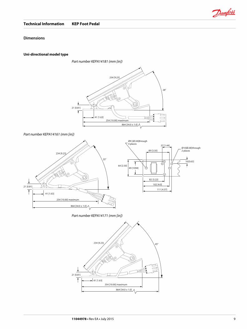
Uni-directional model type
Part number KEPA14181 (mm [in])
234 [9.23]
28°
21 [0.81]
41 [1.63]254 [10.00] maximum
864 [34.0 ± 1.0]
Part number KEPA14161 (mm [in])
234 [9.23]
35°
21 [0.81]
41 [1.63]
254 [10.00] maximum
864 [34.0 ± 1.0]
Ø9 [(Ø.34)] through4 places
37 [1.44]
89 [3.50]
64 [2.50]49 [1094]
Ø10 [Ø.38] through2 places
16 [0.63]
82 [3.22]
102 [4.0]
111 [4.37]
Part number KEPA14171 (mm [in])
234 [9.23] 45°
21 [0.81]
41 [1.63]
254 [10.00] maximum
864 [34.0 ± 1.0]
Technical Information KEP Foot Pedal
Dimensions
11044978 • Rev EA • July 2015 9
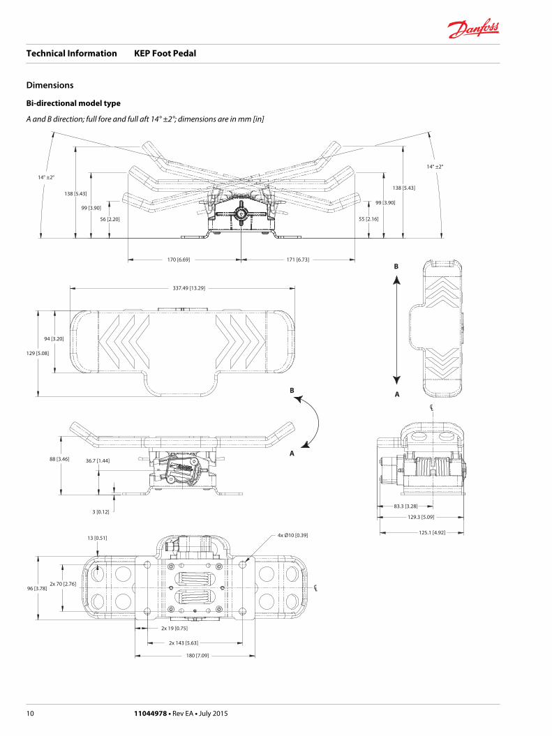
Bi-directional model type
A and B direction; full fore and full aft 14° ±2°; dimensions are in mm [in]
CCLL
CCLL
B
AB
A
14° ±2°
138 [5.43]
14° ±2°
138 [5.43]
99 [3.90]
55 [2.16]
99 [3.90]
56 [2.20]
170 [6.69] 171 [6.73]
337.49 [13.29]
129 [5.08]
94 [3.20]
88 [3.46] 36.7 [1.44]
3 [0.12]
13 [0.51]
96 [3.78]2x 70 [2.76]
2x 19 [0.75]
2x 143 [5.63]
180 [7.09]
4x Ø10 [0.39] 125.1 [4.92]
129.3 [5.09]
83.3 [3.28]
Technical Information KEP Foot Pedal
Dimensions
10 11044978 • Rev EA • July 2015
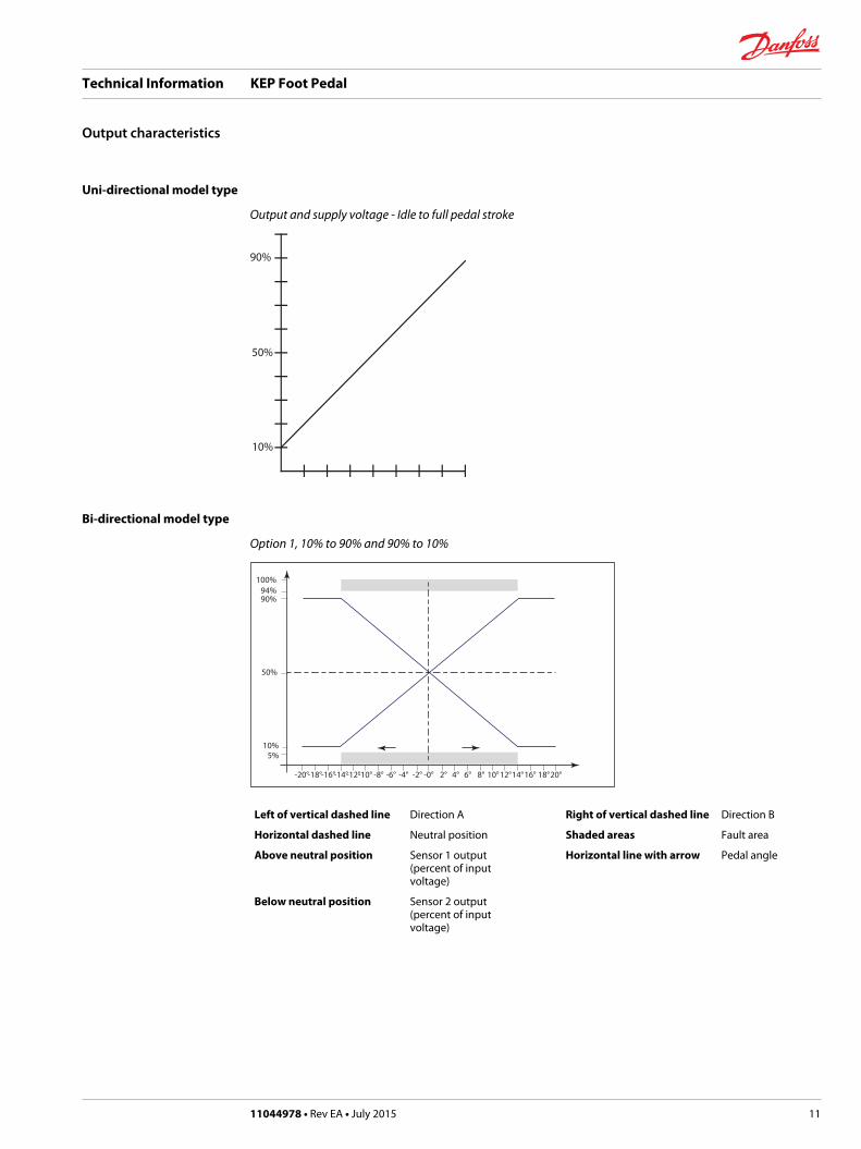
Uni-directional model type
Output and supply voltage - Idle to full pedal stroke
50%
90%
10%
Bi-directional model type
Option 1, 10% to 90% and 90% to 10%
100%
50%
94%90%
10%5%
-20°-18°-16°-14°-12°-10° -8° -6° -4° -2° -0° 2° 4° 6° 8° 10°12°14°16° 18°20°
Left of vertical dashed line Direction A Right of vertical dashed line Direction B
Horizontal dashed line Neutral position Shaded areas Fault area
Above neutral position Sensor 1 output(percent of inputvoltage)
Horizontal line with arrow Pedal angle
Below neutral position Sensor 2 output(percent of inputvoltage)
Technical Information KEP Foot Pedal
Output characteristics
11044978 • Rev EA • July 2015 11
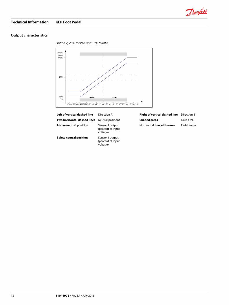
Option 2, 20% to 90% and 10% to 80%
100%
50%
94%90%
10%5%
-20°-18°-16°-14°-12°-10° -8° -6° -4° -2° -0° 2° 4° 6° 8° 10°12°14°16° 18°20°
Left of vertical dashed line Direction A Right of vertical dashed line Direction B
Two horizontal dashed lines Neutral positions Shaded areas Fault area
Above neutral position Sensor 2 output(percent of inputvoltage)
Horizontal line with arrow Pedal angle
Below neutral position Sensor 1 output(percent of inputvoltage)
Technical Information KEP Foot Pedal
Output characteristics
12 11044978 • Rev EA • July 2015
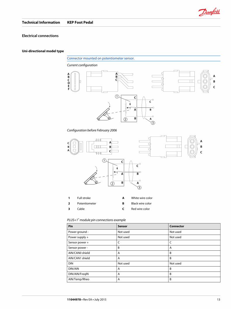
Uni-directional model type
Connector mounted on potentiometer sensor.
Current configuration
ABC
ABCDEF
A
B
C
A
B
C
A
B
C
2
1
3
Configuration before February 2006
ABC
A
B
C
A
B
C
A
B
C1
32
ABC
1 Full stroke A White wire color
2 Potentiometer B Black wire color
3 Cable C Red wire color
PLUS+1® module pin connections example
Pin Sensor Connector
Power ground - Not used Not used
Power supply + Not used Not used
Sensor power + C C
Sensor power - B A
AIN/CAN0 shield A B
AIN/CAN1 shield A B
DIN Not used Not used
DIN/AIN A B
DIN/AIN/FreqIN A B
AIN/Temp/Rheo A B
Technical Information KEP Foot Pedal
Electrical connections
11044978 • Rev EA • July 2015 13
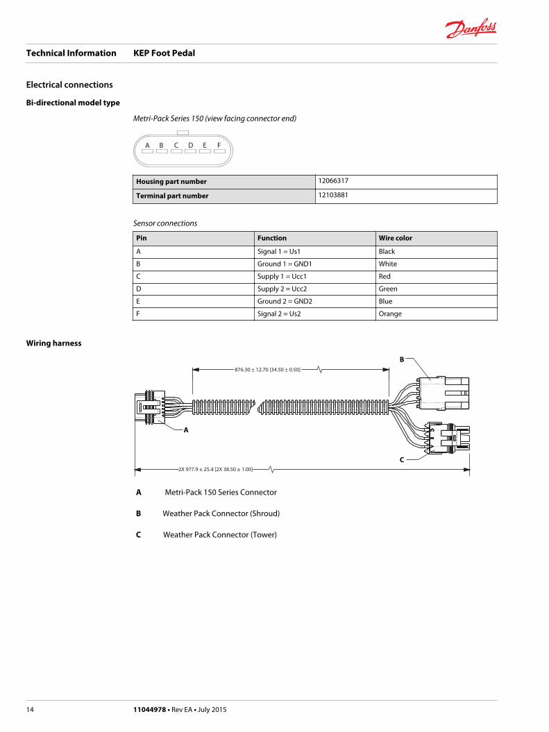
Bi-directional model type
Metri-Pack Series 150 (view facing connector end)
A B C D E F
Housing part number 12066317
Terminal part number 12103881
Sensor connections
Pin Function Wire color
A Signal 1 = Us1 Black
B Ground 1 = GND1 White
C Supply 1 = Ucc1 Red
D Supply 2 = Ucc2 Green
E Ground 2 = GND2 Blue
F Signal 2 = Us2 Orange
Wiring harness
876.30 ± 12.70 [34.50 ± 0.50]
2X 977.9 ± 25.4 [2X 38.50 ± 1.00]
A
B
C
A Metri-Pack 150 Series Connector
B Weather Pack Connector (Shroud)
C Weather Pack Connector (Tower)
Technical Information KEP Foot Pedal
Electrical connections
14 11044978 • Rev EA • July 2015
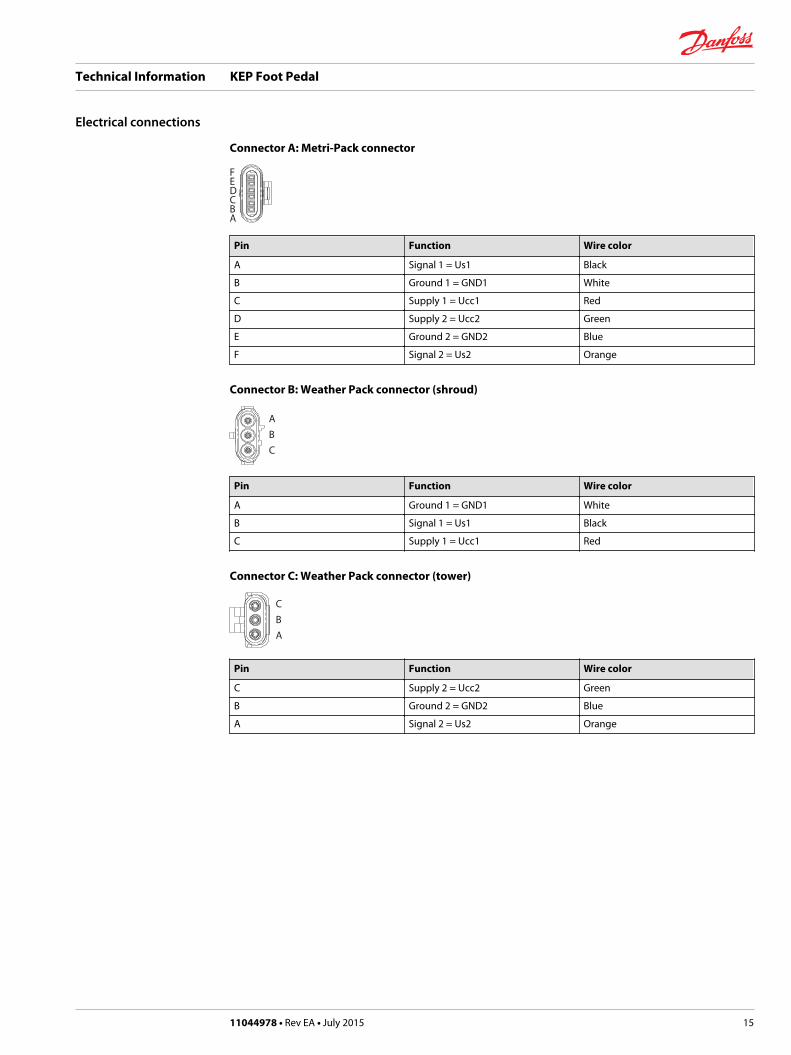
Connector A: Metri-Pack connector
FEDCBA
Pin Function Wire color
A Signal 1 = Us1 Black
B Ground 1 = GND1 White
C Supply 1 = Ucc1 Red
D Supply 2 = Ucc2 Green
E Ground 2 = GND2 Blue
F Signal 2 = Us2 Orange
Connector B: Weather Pack connector (shroud)
ABC
Pin Function Wire color
A Ground 1 = GND1 White
B Signal 1 = Us1 Black
C Supply 1 = Ucc1 Red
Connector C: Weather Pack connector (tower)
CBA
Pin Function Wire color
C Supply 2 = Ucc2 Green
B Ground 2 = GND2 Blue
A Signal 2 = Us2 Orange
Technical Information KEP Foot Pedal
Electrical connections
11044978 • Rev EA • July 2015 15
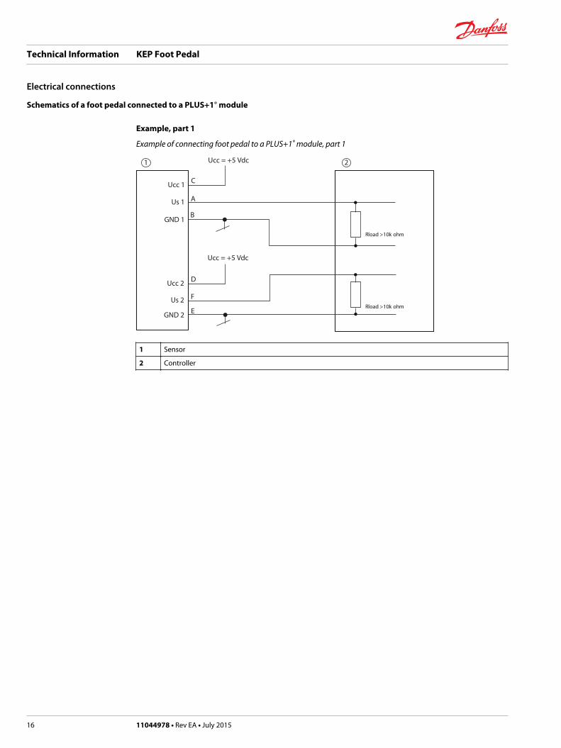
Schematics of a foot pedal connected to a PLUS+1® module
Example, part 1
Example of connecting foot pedal to a PLUS+1® module, part 1
Ucc 1
GND 1
GND 2
Us 1
Ucc 2
Us 2 F
D
E
C
A
B
Ucc = +5 Vdc
Ucc = +5 Vdc
Rload >10k ohm
Rload >10k ohm
1 2
1 Sensor
2 Controller
Technical Information KEP Foot Pedal
Electrical connections
16 11044978 • Rev EA • July 2015
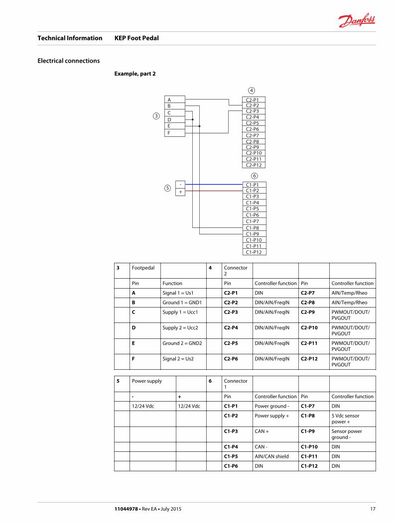
Example, part 2
ABCDEF
-+
C2-P1C2-P2C2-P3C2-P4C2-P5C2-P6C2-P7C2-P8C2-P9C2-P10C2-P11C2-P12
C1-P1C1-P2C1-P3C1-P4C1-P5C1-P6C1-P7C1-P8C1-P9C1-P10C1-P11C1-P12
3
4
5
6
3 Footpedal 4 Connector2
Pin Function Pin Controller function Pin Controller function
A Signal 1 = Us1 C2-P1 DIN C2-P7 AIN/Temp/Rheo
B Ground 1 = GND1 C2-P2 DIN/AIN/FreqIN C2-P8 AIN/Temp/Rheo
C Supply 1 = Ucc1 C2-P3 DIN/AIN/FreqIN C2-P9 PWMOUT/DOUT/PVGOUT
D Supply 2 = Ucc2 C2-P4 DIN/AIN/FreqIN C2-P10 PWMOUT/DOUT/PVGOUT
E Ground 2 = GND2 C2-P5 DIN/AIN/FreqIN C2-P11 PWMOUT/DOUT/PVGOUT
F Signal 2 = Us2 C2-P6 DIN/AIN/FreqIN C2-P12 PWMOUT/DOUT/PVGOUT
5 Power supply 6 Connector1
- + Pin Controller function Pin Controller function
12/24 Vdc 12/24 Vdc C1-P1 Power ground - C1-P7 DIN
C1-P2 Power supply + C1-P8 5 Vdc sensorpower +
C1-P3 CAN + C1-P9 Sensor powerground -
C1-P4 CAN - C1-P10 DIN
C1-P5 AIN/CAN shield C1-P11 DIN
C1-P6 DIN C1-P12 DIN
Technical Information KEP Foot Pedal
Electrical connections
11044978 • Rev EA • July 2015 17
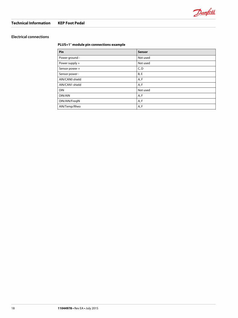
PLUS+1® module pin connections example
Pin Sensor
Power ground - Not used
Power supply + Not used
Sensor power + C, D
Sensor power - B, E
AIN/CAN0 shield A, F
AIN/CAN1 shield A, F
DIN Not used
DIN/AIN A, F
DIN/AIN/FreqIN A, F
AIN/Temp/Rheo A, F
Technical Information KEP Foot Pedal
Electrical connections
18 11044978 • Rev EA • July 2015

Technical Information KEP Foot Pedal
11044978 • Rev EA • July 2015 19

Danfoss Power Solutions is a global manufacturer and supplier of high-quality hydraulic andelectronic components. We specialize in providing state-of-the-art technology and solutionsthat excel in the harsh operating conditions of the mobile off-highway market. Building onour extensive applications expertise, we work closely with our customers to ensureexceptional performance for a broad range of off-highway vehicles.
We help OEMs around the world speed up system development, reduce costs and bringvehicles to market faster.
Danfoss – Your Strongest Partner in Mobile Hydraulics.
Go to www.powersolutions.danfoss.com for further product information.
Wherever off-highway vehicles are at work, so is Danfoss. We offer expert worldwide supportfor our customers, ensuring the best possible solutions for outstanding performance. Andwith an extensive network of Global Service Partners, we also provide comprehensive globalservice for all of our components.
Please contact the Danfoss Power Solution representative nearest you.
Local address:
Danfoss Power Solutions GmbH & Co. OHGKrokamp 35D-24539 Neumünster, GermanyPhone: +49 4321 871 0
Danfoss Power Solutions ApSNordborgvej 81DK-6430 Nordborg, DenmarkPhone: +45 7488 2222
Danfoss Power Solutions (US) Company2800 East 13th StreetAmes, IA 50010, USAPhone: +1 515 239 6000
Danfoss Power Solutions Trading(Shanghai) Co., Ltd.Building #22, No. 1000 Jin Hai RdJin Qiao, Pudong New DistrictShanghai, China 201206Phone: +86 21 3418 5200
Danfoss can accept no responsibility for possible errors in catalogues, brochures and other printed material. Danfoss reserves the right to alter its products without notice. This also applies toproducts already on order provided that such alterations can be made without changes being necessary in specifications already agreed.All trademarks in this material are property of the respective companies. Danfoss and the Danfoss logotype are trademarks of Danfoss A/S. All rights reserved.
11044978 • Rev EA • July 2015 www.danfoss.com © Danfoss A/S, 2015
Products we offer:
• Bent Axis Motors
• Closed Circuit Axial PistonPumps and Motors
• Displays
• Electrohydraulic PowerSteering
• Electrohydraulics
• Hydraulic Power Steering
• Integrated Systems
• Joysticks and ControlHandles
• Microcontrollers andSoftware
• Open Circuit Axial PistonPumps
• Orbital Motors
• PLUS+1® GUIDE
• Proportional Valves
• Sensors
• Steering
• Transit Mixer Drives
Comatrolwww.comatrol.com
Schwarzmüller-Inverterwww.schwarzmueller-inverter.com
Turolla www.turollaocg.com
Hydro-Gearwww.hydro-gear.com
Daikin-Sauer-Danfosswww.daikin-sauer-danfoss.com


![A Survey on Statistical-based Parallel Corpus Alignment Survey on... · Parallel corpora can be uni-directional, bi-directional, or multi-directional [15]. For example, the Bible](https://img.pdfslide.net/doc/110x75/5e815fcc6ea5ba058a605d72/a-survey-on-statistical-based-parallel-corpus-alignment-survey-on-parallel.jpg)