Embed Size (px)
Citation preview

KEPServerEX V5 Help
© 2012 Kepware Technologies
KEPServerEX V5 Help
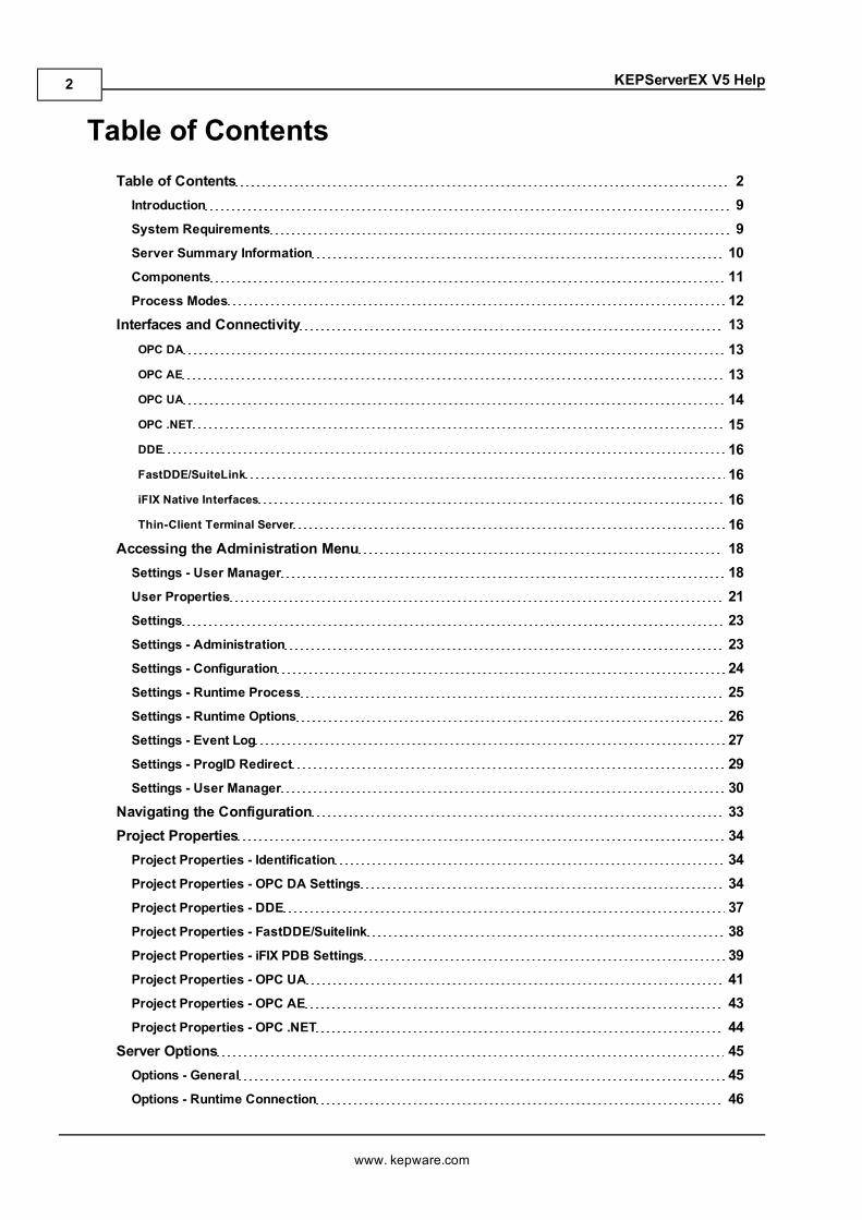
Table of ContentsTable of Contents 2Introduction 9System Requirements 9Server Summary Information 10Components 11Process Modes 12
Interfaces and Connectivity 13OPC DA 13OPC AE 13OPC UA 14OPC .NET 15DDE 16FastDDE/SuiteLink 16iFIX Native Interfaces 16Thin-Client Terminal Server 16
Accessing the Administration Menu 18Settings - User Manager 18User Properties 21Settings 23Settings - Administration 23Settings - Configuration 24Settings - Runtime Process 25Settings - Runtime Options 26Settings - Event Log 27Settings - ProgID Redirect 29Settings - User Manager 30
Navigating the Configuration 33Project Properties 34Project Properties - Identification 34Project Properties - OPC DA Settings 34Project Properties - DDE 37Project Properties - FastDDE/Suitelink 38Project Properties - iFIX PDB Settings 39Project Properties - OPC UA 41Project Properties - OPC AE 43Project Properties - OPC .NET 44
Server Options 45Options - General 45Options - Runtime Connection 46
www. kepware.com
2
KEPServerEX V5 Help
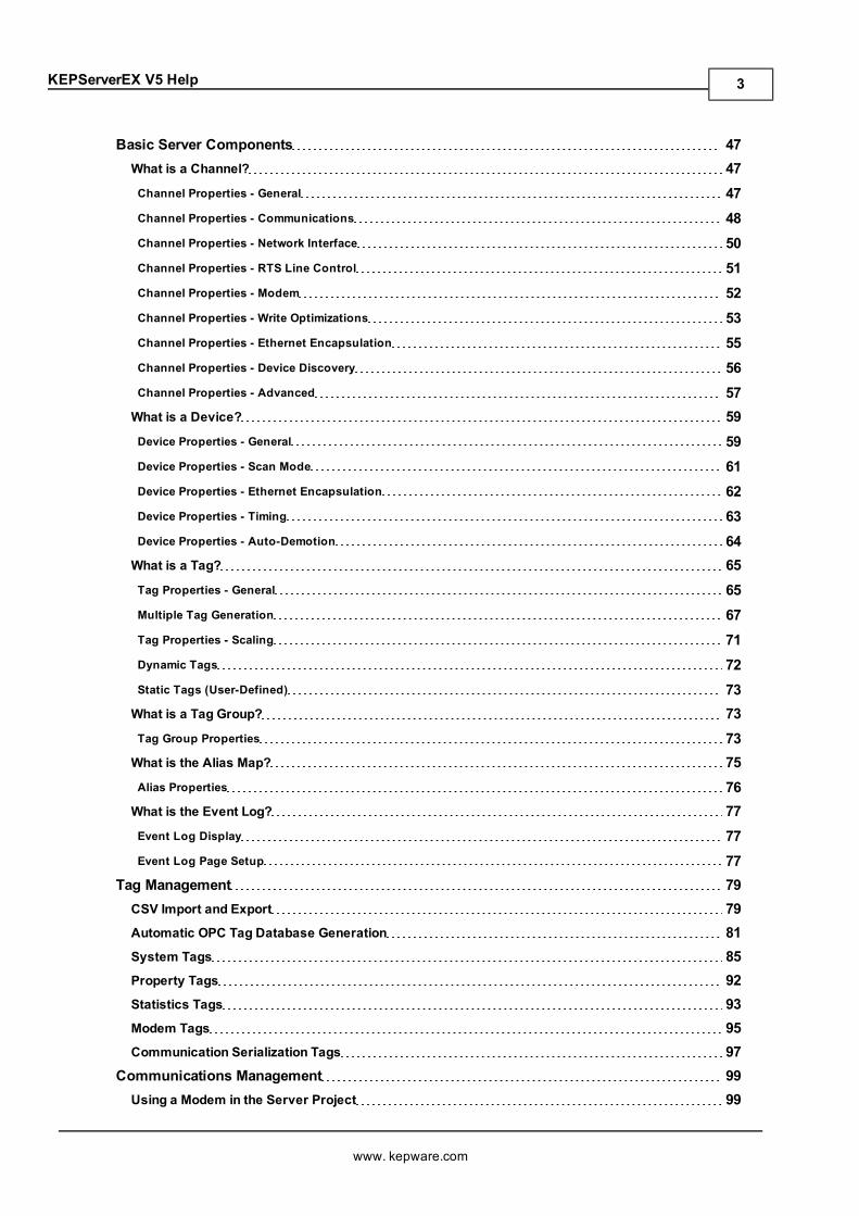
Basic Server Components 47What is a Channel? 47Channel Properties - General 47Channel Properties - Communications 48Channel Properties - Network Interface 50Channel Properties - RTS Line Control 51Channel Properties - Modem 52Channel Properties - Write Optimizations 53Channel Properties - Ethernet Encapsulation 55Channel Properties - Device Discovery 56Channel Properties - Advanced 57What is a Device? 59Device Properties - General 59Device Properties - Scan Mode 61Device Properties - Ethernet Encapsulation 62Device Properties - Timing 63Device Properties - Auto-Demotion 64What is a Tag? 65Tag Properties - General 65Multiple Tag Generation 67Tag Properties - Scaling 71Dynamic Tags 72Static Tags (User-Defined) 73What is a Tag Group? 73Tag Group Properties 73What is the Alias Map? 75Alias Properties 76What is the Event Log? 77Event Log Display 77Event Log Page Setup 77
Tag Management 79CSV Import and Export 79Automatic OPC Tag Database Generation 81System Tags 85Property Tags 92Statistics Tags 93Modem Tags 95Communication Serialization Tags 97
Communications Management 99Using a Modem in the Server Project 99
www. kepware.com
3
KEPServerEX V5 Help
Phonebook Tags 101Phone Number Tags 102Modem Auto-Dial 103
Built-In Diagnostics 105OPC Diagnostic Window 105OPC Diagnostic Events 107Channel Diagnostics 113
iFIX Signal Conditioning Options 117Project Startup for iFIX Applications 122
How Do I... 123How To... Allow Desktop Interactions 123How To... Create and Use an Alias 123How To... Optimize the Server Project 125How To... Properly Name a Channel, Device, Tag, and Tag Group 127How To... Resolve Comm Issues When the DNS/DHCP Device Connected to the Server isPower Cycled 127How To... Use an Alias to Optimize a Project 128How To... Use DDE with the Server 129How To... Use Dynamic Tag Addressing 130How To... Use Ethernet Encapsulation 130How To... Use Net DDE Across a Network 132
Designing a Project 133Running the Server 133Starting a New Project 133Adding and Configuring a Channel 134Adding and Configuring a Device 135Adding User-Defined Tags 136Generating Multiple Tags 138Adding Tag Scaling 141Saving the Project 142Testing the Project 143New Channel - Identification 148New Channel - Device Driver 148New Channel - Communications 149New Channel - Summary 150New Device - Name 151New Device - Model 152New Device - ID 152New Device - Scan Mode 154New Device - Timing 154
www. kepware.com
4
KEPServerEX V5 Help
New Device - Summary 155Error Descriptions 156Server Runtime Error Messages 158'<driver name>' device driver was not found or could not be loaded 159'<server name>' Server Started 159'<server runtime>' successfully configured to run as a system service 159'<server runtime>' successfully removed from the service control manager database 159Attempt to add DDE item '<item name>' failed 159Attempt to add FastDDE/SuiteLink item '<tag name>' failed 160Attempt to add OPC Client item '<item name>' failed 160Attempting to automatically generate tags for device '<device name>' 160Auto generation for tag '<tag name>' already exists and will not be overwritten 161Auto generation produced too many overwrites, stopped posting error messages 161Channel diagnostics started on channel '<channel name>' 161Channel diagnostics stopped on channel '<channel name>' 161Completed automatic tag generation for device '<device name>' 161Configuration session assigned to '<user name>' as Default User has ended 162Configuration session assigned to '<user name>' demoted to Read Only 162Configuration session assigned to '<user name>' promoted to Write Access 162Configuration session started by '<user name>' 162Configuration TCP/IP port number changed to '<port number>' 163Data collection is '<enabled/disabled>' on device '<device name>' 163DDE client attempt to add topic '<topic>' failed 163Delete object '<item name>' failed 163Demo timer started. '<days>' '<hours>' '<minutes>' '<seconds>' 163Demo timer updated. '<time remaining>' 164Demonstration time period has expired for <Feature Name> 164Device '<device name>' has been auto-demoted 164Device '<device name>' has been auto-promoted to determine if communications can be re-estab-lished 165Failed to upload project XML 165FLEXnet Licensing Service must be enabled to process your license. Runtime references are limited todemo operation 165Module '<module>' is unsigned or has a corrupt signature. Runtime references are limited to demooperation 165Move object '<group>' to '<group>' failed 166No device driver DLLs were loaded 166Rejecting attempt to delete referenced object '<item name>' 166Rejecting attempt to move referenced object '<item name>' 166Runtime project replaced from '<project location>' 167
www. kepware.com
5
KEPServerEX V5 Help
Simulation mode is '<enabled/disabled>' on device '<device name>' 167Starting '<driver name>' device driver 167Starting '<plug-in name>' plug-in 167Stopping '<driver name>' device driver 167Stopping '<plug-in name>' plug-in 168The tier information for feature '<feature>' is invalid 168Unable to generate a tag database for device '<device name>'. Reason: '<reason>' 168Unable to generate a tag database for device '<device name>'. The device is not responding 168Unable to load project '<project name>' 168Unable to write to item '<item name>' 169Update of object '<object>' failed 169Write request rejected on item reference '<item name>' since the device it belongs to is disabled 169Write request rejected on Read Only item reference '<item name>' 170Server Configuration Error Messages 170'<device name>' device driver loaded successfully 170'<driver name>' device driver unloaded frommemory 171'<driver name>' device driver was not found or could not be loaded 171'<driver name>' driver does not currently support XML persistence 171'<plug-in>' plug-in was not found or could not be loaded 171A client application has '<enabled/disabled>' auto-demotion on device '<device name>' 172Closing project '<project name>' 172Created backup of project '<project name>' to '<file location>' 172Duplicate Channel Wizard page ID '<ID number>' detected 172Error importing CSV tag record '<record number>': '<tag name>' is not a valid tag group name 173Error importing CSV tag record '<record number>': '<tag name>' is not a valid tag name 173Error importing CSV tag record '<record number>': Missing address 173Error importing CSV tag record '<record number>': Tag or group name exceeds 256 characters 173Failed to reset channel diagnostics 174Failed to retrieve Runtime project 174Invalid Ethernet encapsulation IP '<IP address>' 174Invalid or missing Modem Configuration on channel '<channel name>', substituting '<modem>' 174Invalid XML document '<XML name>' 175Maximum channel count exceeded for the lite version '<driver name>' driver license 175Maximum device count exceeded for the lite version '<driver name>' driver license 175Maximum Runtime tag count exceeded for the lite version '<driver name>' driver license 175Modem initialization failed on channel '<channel name>' 176Opening project '<project name>' 176Required schema file '<schema name>' not found 176Runtime project update failed 176
www. kepware.com
6
KEPServerEX V5 Help
Starting OPC diagnostics 177Stopping OPC diagnostics 177Unable to add channel due to driver-level failure 177Unable to add device due to driver level failure 177Unable to backup project file to '<file name/location>' 177Unable to backup project file to '<file path>' 178Unable to begin device discovery on channel '<Channel Name>' 178Unable to launch OPC Quick Client [Path: '<path>' OS Error: '<error>'] 178Unable to load driver DLL '<driver name>' 179Unable to load the '<driver name>' driver because more than one copy exists ('<driver name>' and'<driver name>') 179Unable to use network adapter '<adapter>' on channel '<channel name>'. Using default networkadapter 179Validation error on '<tag name>': Invalid scaling parameters 179General Operation System Error Messages 180, Error control 180, Forced error control 180, Hardware flow control 181, Software flow control 181Dialing '<phone number>' on line '<modem name>' 181Dialing aborted on '<modem name>' 181Dialing on line '<modem name>' canceled by user 181Failed to open modem line '<modem name>' [TAPI error] 182Hardware error on line '<modem name>' 182Incoming call detected on line '<modem name>' 182Line '<modem name>' connected 182Line '<modem name>' connected at '<baud rate>' baud 183Line '<modem name>' disconnected 183Line '<modem name>' is already in use 183Line dropped at remote site on '<modem name>' 183Modem line closed: '<modem name>' 183Modem line opened: '<modem name>' 184Modem to Modem DCE: '<connection parameters>' 184MODEMSETTINGS unavailable 184No comm handle provided on connect for line '<modem name>' 184No dial tone on '<modem name>' 185Remote line is busy on '<modem name>' 185Remote line is not answering on '<modem name>' 185TAPI configuration has changed, reinitializing... 185TAPI line initialization failed: '<modem name>' 185
www. kepware.com
7

KEPServerEX V5 Help
The phone number is invalid '<phone number>' 186Unable to apply Modem Configuration on line '<modem name>' 186Unable to dial on line '<modem name>' 186Unable to start Net DDE 186iFIX Error Messages 187Attempt to add iFIX PDB item '< item name>' failed 187Failed to enable iFIX PDB support for this server [OS Error = n] 187Unable to enable iFIX PDB support for this server 187Unable to read '<tag name>' on device ' <channel name/device name>' 188
Index 189
www. kepware.com
8
KEPServerEX V5 Help
CONTENTS
IntroductionInterfaces and ConnectivityAccessing the Administration MenuNavigating the ConfigurationBasic Server ComponentsTag ManagementCommunications ManagementBuilt-In DiagnosticsDesigning a ProjectHow Do I... ?Error Descriptions
Note: For information regarding product licensing, refer to the License Utility help file. To access the help filethrough the server Configuration menu, click Help | Server Help | License Utility. To access the help file throughthe server Administration menu, right-click on the KEPServerEX icon in the System Tray and then select Help |License Utility.
Help version 1.255
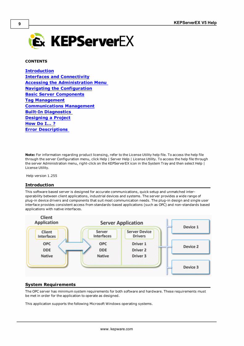
IntroductionThis software based server is designed for accurate communications, quick setup and unmatched inter-operability between client applications, industrial devices and systems. The server provides a wide range ofplug-in device drivers and components that suit most communication needs. The plug-in design and single userinterface provides consistent access from standards-based applications (such as OPC) and non-standards basedapplications with native interfaces.
System RequirementsThe OPC server has minimum system requirements for both software and hardware. These requirements mustbe met in order for the application to operate as designed.
This application supports the following Microsoft Windows operating systems.
www. kepware.com
9
KEPServerEX V5 Help
l Windows 7*l Windows Server 2008/2008 R2*l Windows Vista Business/Ultimate*l Windows Server 2003 SP2*l Windows XP SP2*l Windows 2000 SP4
*When installed on a 64 bit operating system, the application will run in a subsystem of Windows called WOW64(Windows-on-Windows 64 bit). WOW64 is included on all 64 bit versions of Windows and is designed to makedifferences between the operating systems transparent to the user.
The OPC server requires the following hardware at a minimum.
l 2.0 GHz Processorl 1 GB installed RAMl 180 MB available disk spacel Ethernet Card
Server Summary InformationThe server provides basic summary information about itself and the drivers that are currently installed for itsuse.
About the ServerThe server version is readily available for review and provides a means of finding driver-specific information. Toaccess, clickHelp | Support Information in the server main menu. For a display of the versions of all installedplug-in components, click Version.
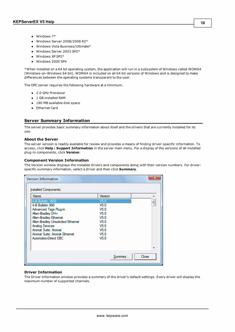
Component Version InformationThe Version window displays the installed drivers and components along with their version numbers. For driver-specific summary information, select a driver and then click Summary.
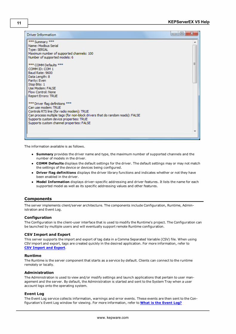
Driver InformationThe Driver Information window provides a summary of the driver's default settings. Every driver will display themaximum number of supported channels.
www. kepware.com
10
KEPServerEX V5 Help
The information available is as follows.
l Summary provides the driver name and type, the maximum number of supported channels and thenumber of models in the driver.
l COMM Defaults displays the default settings for the driver. The default settings may or may not matchthe settings of the device or devices being configured.
l Driver flag definitions displays the driver library functions and indicates whether or not they havebeen enabled in the driver.
l Model Information displays driver-specific addressing and driver features. It lists the name for eachsupported model as well as its specific addressing values and other features.
ComponentsThe server implements client/server architecture. The components include Configuration, Runtime, Admin-istration and Event Log.
ConfigurationThe Configuration is the client-user interface that is used to modify the Runtime's project. The Configuration canbe launched by multiple users and will eventually support remote Runtime configuration.
CSV Import and ExportThis server supports the import and export of tag data in a Comma Separated Variable (CSV) file. When usingCSV import and export, tags are created quickly in the desired application. For more information, refer toCSV Import and Export.
RuntimeThe Runtime is the server component that starts as a service by default. Clients can connect to the runtimeremotely or locally.
AdministrationThe Administration is used to view and/or modify settings and launch applications that pertain to user man-agement and the server. By default, the Administration is started and sent to the System Tray when a useraccount logs onto the operating system.
Event LogThe Event Log service collects information, warnings and error events. These events are then sent to the Con-figuration's Event Log window for viewing. For more information, refer toWhat is the Event Log?
www. kepware.com
11
KEPServerEX V5 Help
Process ModesThe Runtime's process mode can be changed while the server is running; however, doing so while a client is con-nected will interrupt the connection for a short period of time. The modes of operation are System Service andInteractive.
System ServiceBy default, the server is installed and runs as a service. When System Service is selected, the Runtime does notrequire user intervention and will start when the operating system opens. This provides user independent accessto the server by the clients.
InteractiveWhen Interactive is selected, the Runtime will remain stopped until a client attempts to connect to it. Oncestarted, it will run until all clients have disconnected and then shutdown. The Runtime will also shutdown if theuser account logs off the operation system.
Note: The Runtime's process mode may be changed to meet client applications' needs through the Admin-istration settings dialogs.
System Service is required for the following conditions:
l When iFIX is required to run on an operating system while UAC is enabled.
Interactive is required for the following conditions:
l When a communication interface (such as DDE) must exchange information with the user desktop andthe server is installed on Windows Vista, Windows Server 2008, or later operating systems.
See Also: Settings - Runtime Process and How To...Allow Desktop Interactions.
www. kepware.com
12
KEPServerEX V5 Help
Interfaces and ConnectivityThis communications server simultaneously supports the client/server technologies listed below. Client appli-cations can use any of these technologies to access data from the server at the same time. For more informationon a specific interface, select a link from the list below.
OPC DAOPC AEOPC UAOPC .NETDDEFastDDE/SuiteLinkiFIX Native InterfacesThin-Client Terminal Server
OPC DASupported Versions1.0a2.05a3.0
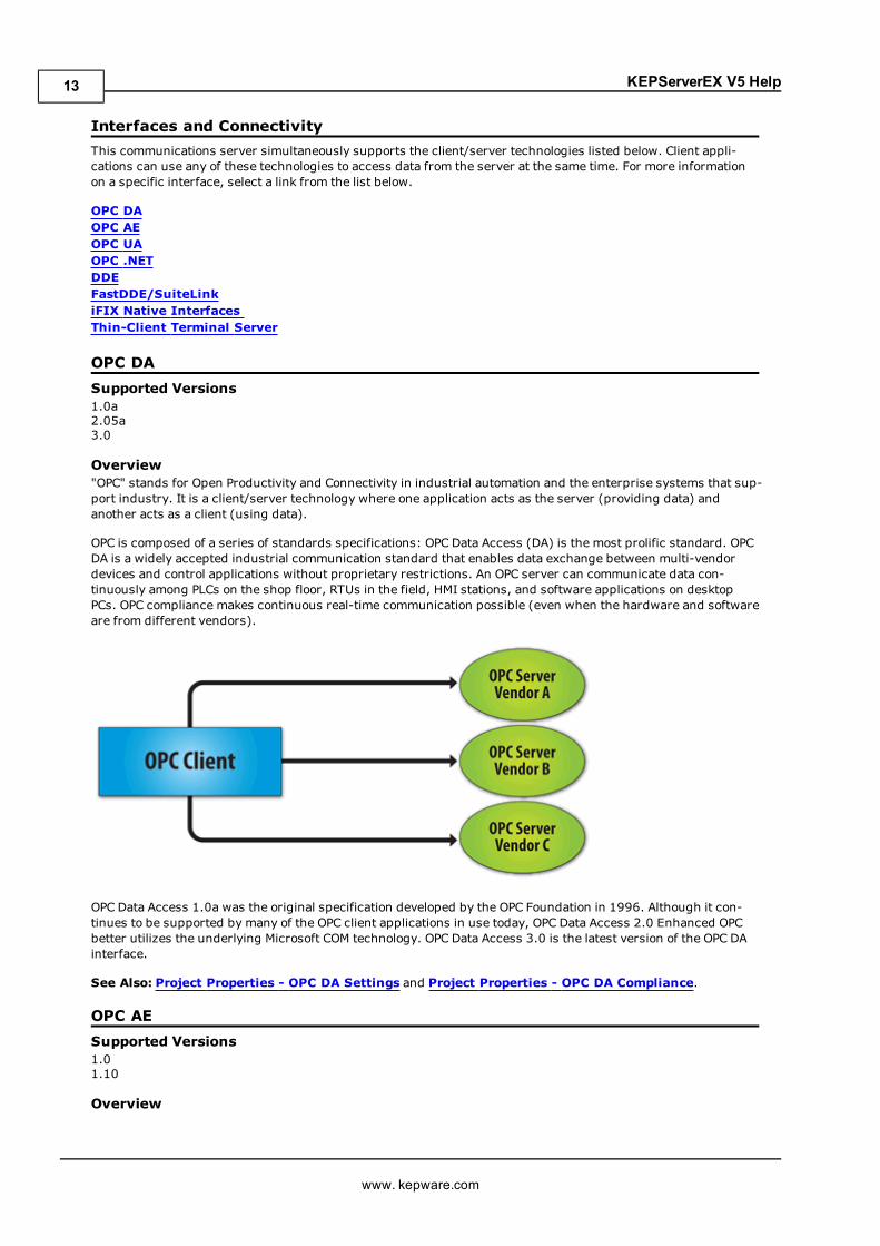
Overview"OPC" stands for Open Productivity and Connectivity in industrial automation and the enterprise systems that sup-port industry. It is a client/server technology where one application acts as the server (providing data) andanother acts as a client (using data).
OPC is composed of a series of standards specifications: OPC Data Access (DA) is the most prolific standard. OPCDA is a widely accepted industrial communication standard that enables data exchange between multi-vendordevices and control applications without proprietary restrictions. An OPC server can communicate data con-tinuously among PLCs on the shop floor, RTUs in the field, HMI stations, and software applications on desktopPCs. OPC compliance makes continuous real-time communication possible (even when the hardware and softwareare from different vendors).
OPC Data Access 1.0a was the original specification developed by the OPC Foundation in 1996. Although it con-tinues to be supported by many of the OPC client applications in use today, OPC Data Access 2.0 Enhanced OPCbetter utilizes the underlying Microsoft COM technology. OPC Data Access 3.0 is the latest version of the OPC DAinterface.
See Also: Project Properties - OPC DA Settings and Project Properties - OPC DA Compliance.
OPC AESupported Versions1.01.10
Overview
www. kepware.com
13
KEPServerEX V5 Help
OPC Alarms & Events (AE) is a specification developed by the OPC Foundation to standardize the way that alarmand event information is shared among systems. Using the standard, AE clients can receive alarms and eventnotices for equipment safety limits, system errors, and other abnormal situations.
Simple EventsSimple Events include the server events displayed in the Event Log (such as startup, shutdown, warning, anderror events). The server supports the following filtering options for Simple Events for AE clients:
l Event Type: Simple.l Event Category: Filter by server-defined categories. Each event is assigned to one category. Descrip-tions of the categories are as follows:
l Runtime Error Events: Simple events that are shown as errors in the Event Log.l Runtime Warning Events: Simple events that are shown as warnings in the Event Log.l Runtime Information Events: Simple events that are shown as informational in the EventLog.
Condition EventsCondition Events are created by server conditions, which are currently only configurable through the use of theAlarms & Events Plug-In. The server supports the following filtering options for Condition Events for AE clients:
1. Event: Condition.
2. Category: Filter by server-defined categories. Each event is assigned to one category. Descriptions of thecategories are as follows:
l Level Alarms: Events that are generated by process level conditions. For example, tank level >10.
l Deviation Alarms: Events that are generated by deviation conditions. For example, tank level+/- 10.
l Rate of Change Alarms: Events that are generated by rate of change conditions.
3. Severity: Filter by severity level. Levels range from 0 to 1000; 1000 is the most severe. Each event isassigned a severity.
4. Area: Filter by a process area to get alarms and events from only that area. An area is used to organizealarm and event information.
5. Source: Filter by source to get events from only that source. A source is an Alarms & Events area that wascreated by a source (such as a server tag) that belongs to an area.
Note: The Alarms & Events Plug-In allows conditions to be configured through server tags. For example, a Tem-perature Tag can be configured through the Alarms & Events Plug-In to generate an event when the maximumvalue is reached. For more information on the Alarms & Events Plug-In, contact an OPC vendor.
See Also: Project Properties - OPC AE
Optional InterfacesThe AE server interface does not support the following optional interfaces:
l IOPCEventServer::QueryEventAttributes: This interface manages event attributes, which are not sup-ported by the server. Attributes allow custom information to be added to an event (such as special mes-sages or server tag values). This also applies to the IOPCEventSubscriptionMgt::SelectReturnedAttributesinterface and the IOPCEventSubscriptionMgt::GetReturnedAttributes interface.
l IOPCEventServer::TranslateToItemIDs: This interface allows AE clients to get the OPC DA itemrelated to the event. This is because in some cases, events are related to the value of a server tag.
l IOPCEventServer2: This interface allows clients to enable/disable areas and sources. This interface isnot supported by the server, because it would allow one client to enable/disable an area or source for allclients.
Note: The AE server interface does not support tracking events.
OPC UASupported Version1.01 optimized binary TCP
www. kepware.com
14
KEPServerEX V5 Help
OverviewOPC Unified Architecture (UA) is an open standard created by the OPC Foundation with help from dozens ofmember organizations. It provides an additional way to share factory floor data to business systems (from shop-floor to top-floor). UA also offers a secure method for remote client-to-server connectivity without depending onMicrosoft DCOM. It has the ability to connect securely through firewalls and over VPN connections. This imple-mentation of the UA server supports optimized binary TCP and the DA data model.
Note: Currently, neither UA via HTTP/SOAP web services nor for complex data is supported. For more infor-mation, refer to the OPC UA Configuration Manager help file.
OPC UA ProfilesOPC UA is a multi-part specification that defines a number of services and information models referred to as fea-tures. Features are grouped into Profiles, which are then used to describe the functionality supported by a UAserver or client. For a full list and a description of each OPC UA profile, refer to http://www.opc-foundation.org/profilereporting/index.htm.
Fully Supported OPC UA Profiles
l Standard UA Server Profilel Core Server Facetl Data Access Server Facetl SecurityPolicy - Basic128Rsa15l SecurityPolicy - Basic256l SecurityPolicy - Nonel UA-TCP UA-SC UA Binary
Partially Supported OPC UA Profiles
l Base Server Behavior Facet
Note: This profile does not support the Security Administrator – XML Schema.
See Also: Project Properties - OPC UA
OPC .NETSupported Version1.20.2
OverviewOPC .NET is a family of APIs provided by the OPC Foundation that leverage Microsoft's .NET technology and allow.NET clients to connect to the server. This server supports OPC .NET 3.0 WCF, formally known as OPC Xi. Unlikeother OPC .NET APIs, OPC .NET 3.0 uses Windows Communication Foundation (WCF) for connectivity, thus avoid-ing DCOM issues and providing the following benefits:
l Secure communication via multiple communications bindings (such as Named Pipe, TCP, Basic HTTP, andWs HTTP).
l Consolidation of OPC Classic Interfaces.l Simple development, configuration, and deployment of Windows environment.
The server adds OPC .NET 3.0 support using a customized version of the OPC .NET 3.0 WCF Wrapper supplied bythe OPC Foundation. The wrapper runs as a system service called "xi_server_runtime.exe". It wraps the existingserver's OPC AE and DA interfaces, thus providing WCF clients access to the server's tag and alarm data. It doesnot support Historical Data Access (HDA).
Note: The OPC .NET service is only started when the server starts and the interface is enabled. Unlike OPC DA,clients cannot launch the server. For more information on configuration, refer to Project Properties – OPC.NET.
RequirementsTo install and use OPC .NET 3.0, Microsoft .NET 3.5 must be present on the machine before server installation.
www. kepware.com
15
KEPServerEX V5 Help
DDESupported FormatsCF_TextXL_TableAdvanced DDENetwork DDE
OverviewAlthough this server is first and foremost an OPC server, there are still a number of applications that requireDynamic Data Exchange (DDE) to share data. As such, the server provides access to DDE applications that sup-port one of the following DDE formats: CF_Text, XL_Table, and Advanced DDE. CF_Text and XL_Table are stand-ard DDE formats developed by Microsoft for use with all DDE aware applications. Advanced DDE is a highperformance format supported by a number of client applications specific to the industrial market.
CF_Text and XL_TableThe DDE format CF_Text is the standard DDE format as defined by Microsoft. All DDE aware applications supportthe CF_Text format. XL_Table is the standard DDE format as defined by Microsoft that is used by Excel. For moreinformation on DDE, refer toHow To... Use DDE with the Server.
Advanced DDEAdvanced DDE is the DDE format defined by Rockwell Automation. Today, all Rockwell Client applications areAdvanced DDE aware. Advanced DDE is a variation on the normal CF_Text format, which allows larger amounts ofdata to transfer between applications at higher rates of speed (and with better error handling).
Network DDENetwork DDE (Net DDE) is the standard for remote DDE connection as defined by Microsoft. It uses the CF_Textformat. For more information on Net DDE, refer toHow to... Use Net DDE Across a Network.
RequirementsIn order for the DDE interface to connect with the server, the Runtime must be allowed to interact with the desk-top. For more information, refer toHow To... Allow Desktop Interactions.
See Also: Project Properties - DDE
FastDDE/SuiteLinkOverviewFastDDE is a DDE format defined by Wonderware Corporation. It allows larger amounts of data to transferbetween applications at higher speed (and with better error handling) than generic DDE. SuiteLink is aclient/server communication method that has succeeded FastDDE. It is TCP/IP based and has improved band-width and speed. Both FastDDE and SuiteLink are supported by all Wonderware client applications.
Note: The Wonderware connectivity toolkit is used to simultaneously provide OPC and FastDDE/SuiteLink con-nectivity while allowing for quick access to device data without the use of intermediary bridging software.
RequirementsIn order for the FastDDE interface to connect with the server, the Runtime must be allowed to interact with thedesktop. For more information, refer toHow To... Allow Desktop Interactions.
See Also: Project Properties - FastDDE/SuiteLink
iFIX Native InterfacesOverviewThe iFIX Native Interface simplifies the connection task by allowing a direct connection to the local iFIX applicationwithout the use of the iFIX OPC Power Tool. When supported, this interface also has the ability to refine the con-nection between the server and the iFIX Process Database (PDB).
See Also: Project Properties - iFIX PDB Settings
Thin-Client Terminal ServerOverviewWindows Remote Desktop, which was formerly called Terminal Services, is a Microsoft Windows component thatallows users to access data and applications on a remote computer over a network. It also enables com-munications servers to be configured via remote client machines.
www. kepware.com
16

KEPServerEX V5 Help
www. kepware.com
17
KEPServerEX V5 Help
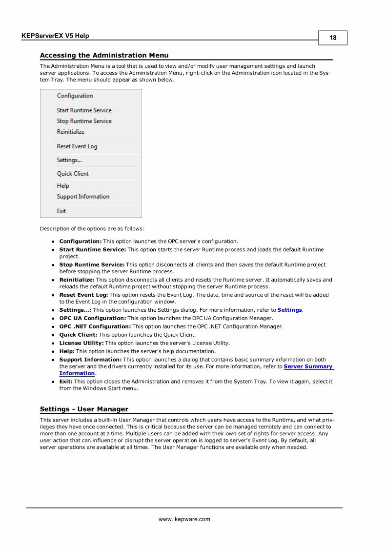
Accessing the Administration MenuThe Administration Menu is a tool that is used to view and/or modify user management settings and launchserver applications. To access the Administration Menu, right-click on the Administration icon located in the Sys-tem Tray. The menu should appear as shown below.
Description of the options are as follows:
l Configuration: This option launches the OPC server's configuration.l Start Runtime Service: This option starts the server Runtime process and loads the default Runtimeproject.
l Stop Runtime Service: This option disconnects all clients and then saves the default Runtime projectbefore stopping the server Runtime process.
l Reinitialize: This option disconnects all clients and resets the Runtime server. It automatically saves andreloads the default Runtime project without stopping the server Runtime process.
l Reset Event Log: This option resets the Event Log. The date, time and source of the reset will be addedto the Event Log in the configuration window.
l Settings...: This option launches the Settings dialog. For more information, refer to Settings.l OPC UA Configuration: This option launches the OPC UA Configuration Manager.l OPC .NET Configuration: This option launches the OPC .NET Configuration Manager.l Quick Client: This option launches the Quick Client.l License Utility: This option launches the server's License Utility.l Help: This option launches the server's help documentation.l Support Information: This option launches a dialog that contains basic summary information on boththe server and the drivers currently installed for its use. For more information, refer to Server SummaryInformation.
l Exit: This option closes the Administration and removes it from the System Tray. To view it again, select itfrom the Windows Start menu.
Settings - User ManagerThis server includes a built-in User Manager that controls which users have access to the Runtime, and what priv-ileges they have once connected. This is critical because the server can be managed remotely and can connect tomore than one account at a time. Multiple users can be added with their own set of rights for server access. Anyuser action that can influence or disrupt the server operation is logged to server's Event Log. By default, allserver operations are available at all times. The User Manager functions are available only when needed.
www. kepware.com
18
KEPServerEX V5 Help
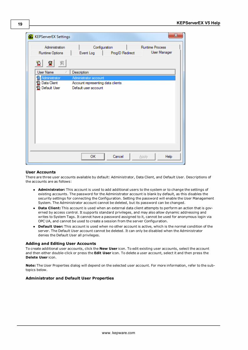
User AccountsThere are three user accounts available by default: Administrator, Data Client, and Default User. Descriptions ofthe accounts are as follows:
l Administrator: This account is used to add additional users to the system or to change the settings ofexisting accounts. The password for the Administrator account is blank by default, as this disables thesecurity settings for connecting the Configuration. Setting the password will enable the User ManagementSystem. The Administrator account cannot be deleted, but its password can be changed.
l Data Client: This account is used when an external data client attempts to perform an action that is gov-erned by access control. It supports standard privileges, and may also allow dynamic addressing andwrites to System Tags. It cannot have a password assigned to it, cannot be used for anonymous login viaOPC UA, and cannot be used to create a session from the server Configuration.
l Default User: This account is used when no other account is active, which is the normal condition of theserver. The Default User account cannot be deleted. It can only be disabled when the Administratordenies the Default User all privileges.
Adding and Editing User AccountsTo create additional user accounts, click theNew User icon. To edit existing user accounts, select the accountand then either double-click or press the Edit User icon. To delete a user account, select it and then press theDelete User icon.
Note: The User Properties dialog will depend on the selected user account. For more information, refer to the sub-topics below.
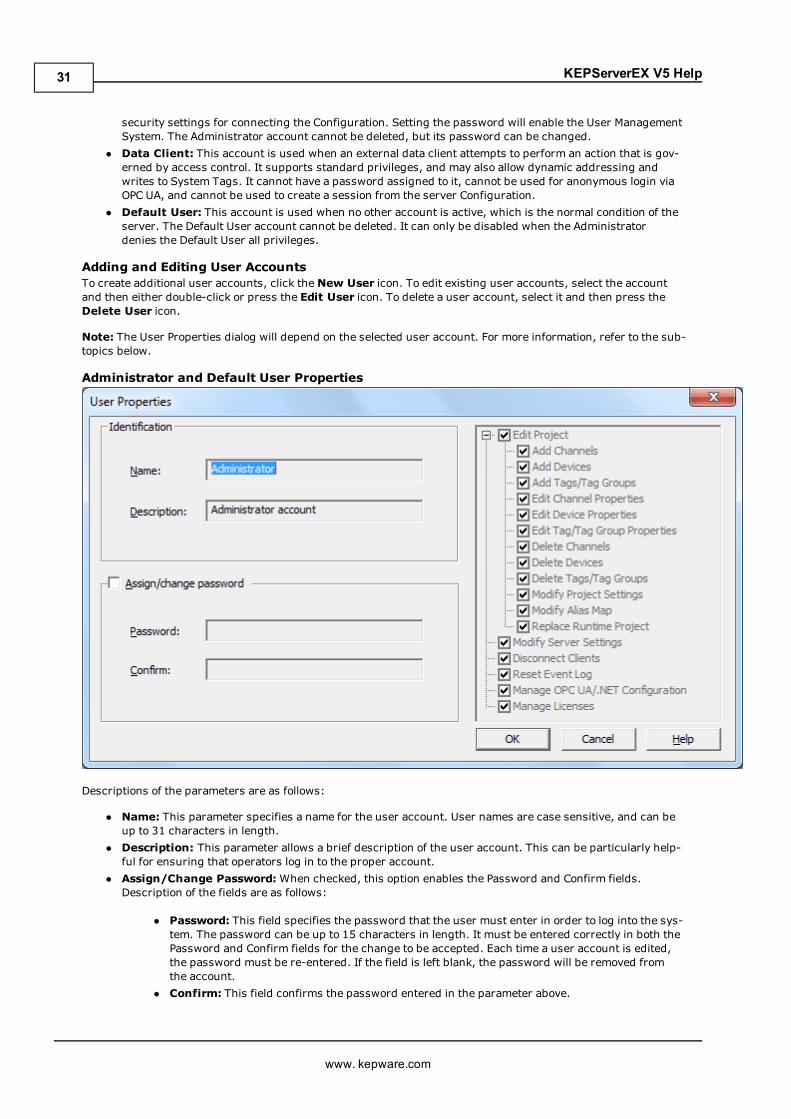
Administrator and Default User Properties
www. kepware.com
19
KEPServerEX V5 Help
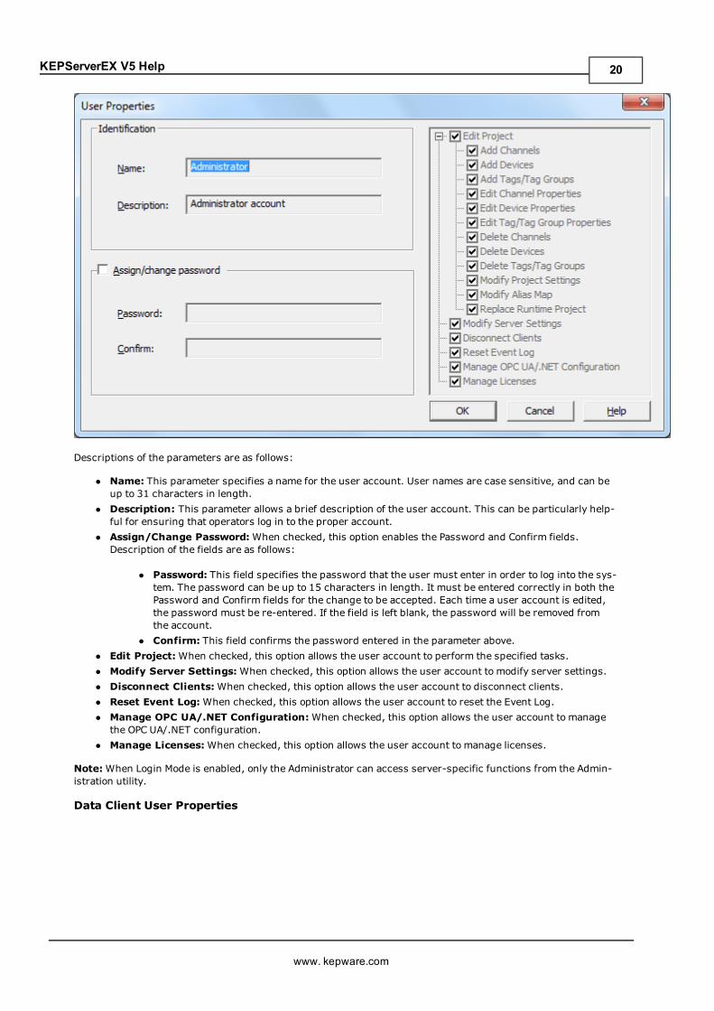
Descriptions of the parameters are as follows:
l Name: This parameter specifies a name for the user account. User names are case sensitive, and can beup to 31 characters in length.
l Description: This parameter allows a brief description of the user account. This can be particularly help-ful for ensuring that operators log in to the proper account.
l Assign/Change Password:When checked, this option enables the Password and Confirm fields.Description of the fields are as follows:
l Password: This field specifies the password that the user must enter in order to log into the sys-tem. The password can be up to 15 characters in length. It must be entered correctly in both thePassword and Confirm fields for the change to be accepted. Each time a user account is edited,the password must be re-entered. If the field is left blank, the password will be removed fromthe account.
l Confirm: This field confirms the password entered in the parameter above.l Edit Project:When checked, this option allows the user account to perform the specified tasks.l Modify Server Settings:When checked, this option allows the user account to modify server settings.l Disconnect Clients:When checked, this option allows the user account to disconnect clients.l Reset Event Log:When checked, this option allows the user account to reset the Event Log.l Manage OPC UA/.NET Configuration:When checked, this option allows the user account to managethe OPC UA/.NET configuration.
l Manage Licenses:When checked, this option allows the user account to manage licenses.
Note:When Login Mode is enabled, only the Administrator can access server-specific functions from the Admin-istration utility.
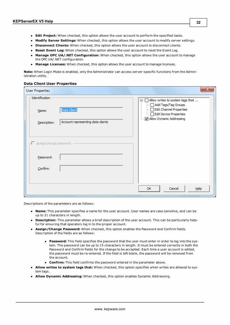
Data Client User Properties
www. kepware.com
20
KEPServerEX V5 Help
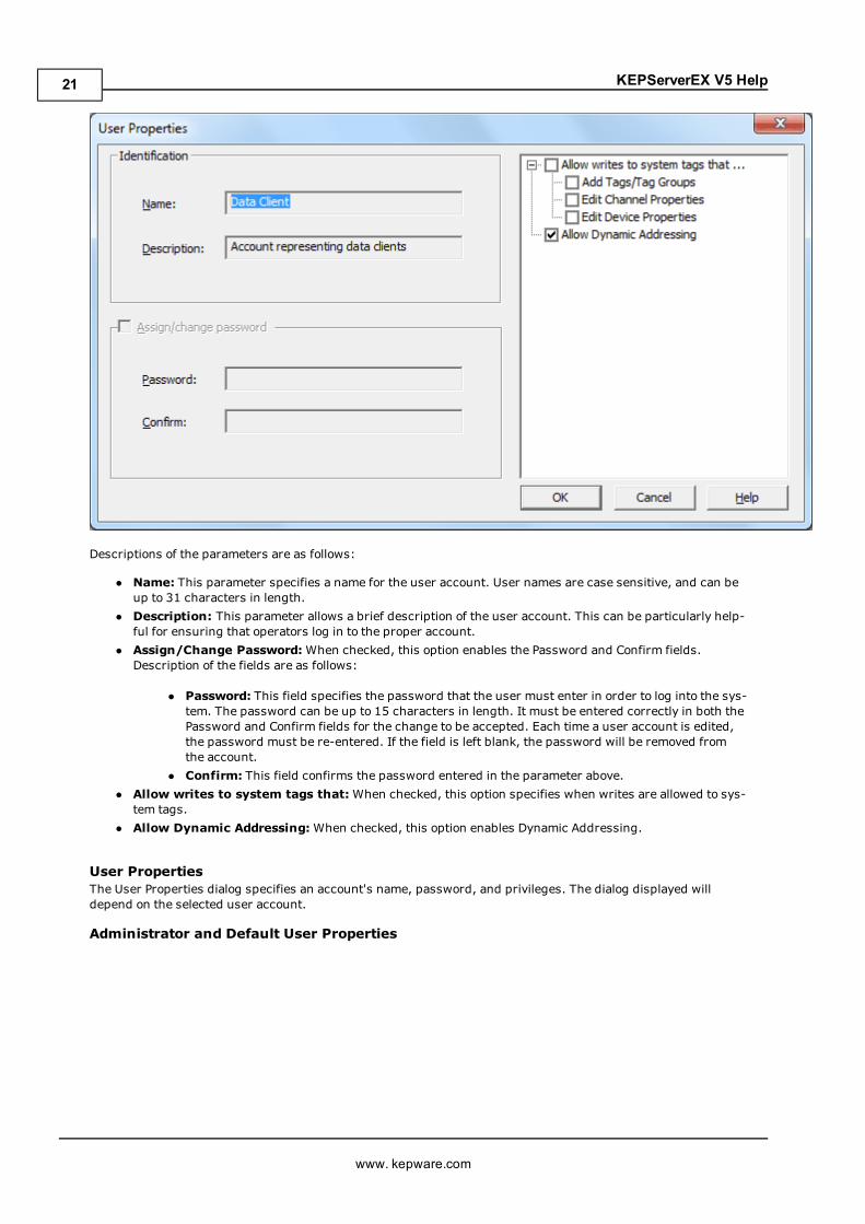
Descriptions of the parameters are as follows:
l Name: This parameter specifies a name for the user account. User names are case sensitive, and can beup to 31 characters in length.
l Description: This parameter allows a brief description of the user account. This can be particularly help-ful for ensuring that operators log in to the proper account.
l Assign/Change Password:When checked, this option enables the Password and Confirm fields.Description of the fields are as follows:
l Password: This field specifies the password that the user must enter in order to log into the sys-tem. The password can be up to 15 characters in length. It must be entered correctly in both thePassword and Confirm fields for the change to be accepted. Each time a user account is edited,the password must be re-entered. If the field is left blank, the password will be removed fromthe account.
l Confirm: This field confirms the password entered in the parameter above.l Allow writes to system tags that:When checked, this option specifies when writes are allowed to sys-tem tags.
l Allow Dynamic Addressing:When checked, this option enables Dynamic Addressing.
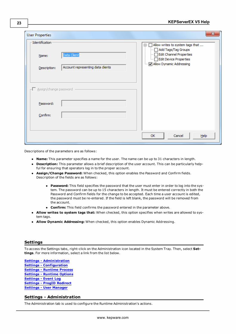
User PropertiesThe User Properties dialog specifies an account's name, password, and privileges. The dialog displayed willdepend on the selected user account.
Administrator and Default User Properties
www. kepware.com
21

KEPServerEX V5 Help
Descriptions of the parameters are as follows:
l Name: This parameter specifies a name for the user. The name can be up to 31 characters in length.l Description: This parameter allows a brief description of the user account. This can be particularly help-ful for ensuring that operators log in to the proper account.
l Assign/Change Password:When checked, this option enables the Password and Confirm fields.Description of the fields are as follows:
l Password: This field specifies the password that the user must enter in order to log into the sys-tem. The password can be up to 15 characters in length. It must be entered correctly in both thePassword and Confirm fields for the change to be accepted. Each time a user account is edited,the password must be re-entered. If the field is left blank, the password will be removed fromthe account.
l Confirm: This field confirms the password entered in the parameter above.l Edit Project:When checked, this option allows the user account to perform the specified tasks.l Modify Server Settings:When checked, this option allows the user account to modify server settings.l Disconnect Clients:When checked, this option allows the user account to disconnect clients.l Reset Event Log:When checked, this option allows the user account to reset the Event Log.l Manage OPC UA/.NET Configuration:When checked, this option allows the user account to managethe OPC UA/.NET configuration.
l Manage Licenses:When checked, this option allows the user account to manage licenses.
Note:When Login Mode is enabled, only the Administrator can access server-specific functions from the Admin-istration utility.
Data Client User Properties
www. kepware.com
22
KEPServerEX V5 Help
Descriptions of the parameters are as follows:
l Name: This parameter specifies a name for the user. The name can be up to 31 characters in length.l Description: This parameter allows a brief description of the user account. This can be particularly help-ful for ensuring that operators log in to the proper account.
l Assign/Change Password:When checked, this option enables the Password and Confirm fields.Description of the fields are as follows:
l Password: This field specifies the password that the user must enter in order to log into the sys-tem. The password can be up to 15 characters in length. It must be entered correctly in both thePassword and Confirm fields for the change to be accepted. Each time a user account is edited,the password must be re-entered. If the field is left blank, the password will be removed fromthe account.
l Confirm: This field confirms the password entered in the parameter above.l Allow writes to system tags that:When checked, this option specifies when writes are allowed to sys-tem tags.
l Allow Dynamic Addressing:When checked, this option enables Dynamic Addressing.
SettingsTo access the Settings tabs, right-click on the Administration icon located in the System Tray. Then, select Set-tings. For more information, select a link from the list below.
Settings - AdministrationSettings - ConfigurationSettings - Runtime ProcessSettings - Runtime OptionsSettings - Event LogSettings - ProgID RedirectSettings - User Manager
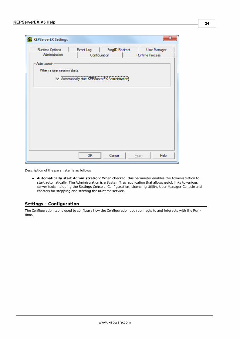
Settings - AdministrationThe Administration tab is used to configure the Runtime Administration's actions.
www. kepware.com
23
KEPServerEX V5 Help
Description of the parameter is as follows:
l Automatically start Administration:When checked, this parameter enables the Administration tostart automatically. The Administration is a System Tray application that allows quick links to variousserver tools including the Settings Console, Configuration, Licensing Utility, User Manager Console andcontrols for stopping and starting the Runtime service.
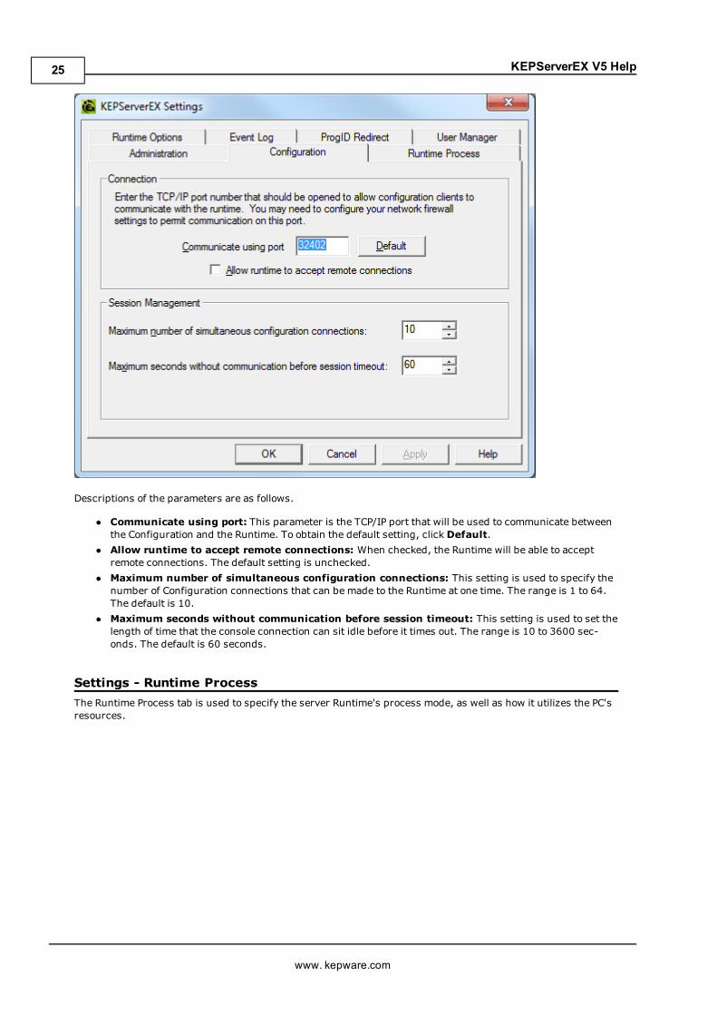
Settings - ConfigurationThe Configuration tab is used to configure how the Configuration both connects to and interacts with the Run-time.
www. kepware.com
24
KEPServerEX V5 Help
Descriptions of the parameters are as follows.
l Communicate using port: This parameter is the TCP/IP port that will be used to communicate betweenthe Configuration and the Runtime. To obtain the default setting, click Default.
l Allow runtime to accept remote connections: When checked, the Runtime will be able to acceptremote connections. The default setting is unchecked.
l Maximum number of simultaneous configuration connections: This setting is used to specify thenumber of Configuration connections that can be made to the Runtime at one time. The range is 1 to 64.The default is 10.
l Maximum seconds without communication before session timeout: This setting is used to set thelength of time that the console connection can sit idle before it times out. The range is 10 to 3600 sec-onds. The default is 60 seconds.
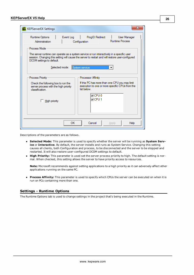
Settings - Runtime ProcessThe Runtime Process tab is used to specify the server Runtime's process mode, as well as how it utilizes the PC'sresources.
www. kepware.com
25
KEPServerEX V5 Help
Descriptions of the parameters are as follows.
l Selected Mode: This parameter is used to specify whether the server will be running as System Serv-ice or Interactive. By default, the server installs and runs as System Service. Changing this settingcauses all clients, both Configuration and process, to be disconnected and the server to be stopped andrestarted. It will also restore user-configured DCOM settings to default.
l High Priority: This parameter is used set the server process priority to high. The default setting is nor-mal. When checked, this setting allows the server to have priority access to resources.
Note: Microsoft recommends against setting applications to a high priority as it can adversely affect otherapplications running on the same PC.
l Process Affinity: This parameter is used to specify which CPUs the server can be executed on when it isrun on PCs containing more than one.
Settings - Runtime OptionsThe Runtime Options tab is used to change settings in the project that's being executed in the Runtime.
www. kepware.com
26
KEPServerEX V5 Help
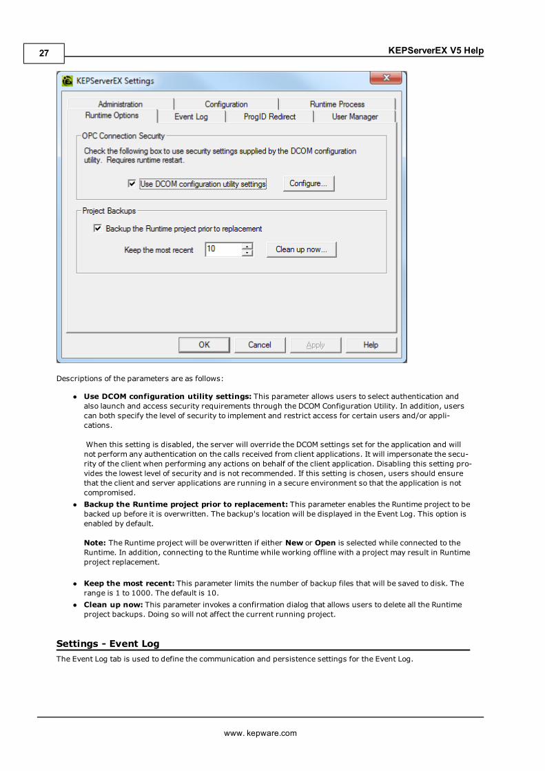
Descriptions of the parameters are as follows:
l Use DCOM configuration utility settings: This parameter allows users to select authentication andalso launch and access security requirements through the DCOM Configuration Utility. In addition, userscan both specify the level of security to implement and restrict access for certain users and/or appli-cations.
When this setting is disabled, the server will override the DCOM settings set for the application and willnot perform any authentication on the calls received from client applications. It will impersonate the secu-rity of the client when performing any actions on behalf of the client application. Disabling this setting pro-vides the lowest level of security and is not recommended. If this setting is chosen, users should ensurethat the client and server applications are running in a secure environment so that the application is notcompromised.
l Backup the Runtime project prior to replacement: This parameter enables the Runtime project to bebacked up before it is overwritten. The backup's location will be displayed in the Event Log. This option isenabled by default.
Note: The Runtime project will be overwritten if either New or Open is selected while connected to theRuntime. In addition, connecting to the Runtime while working offline with a project may result in Runtimeproject replacement.
l Keep the most recent: This parameter limits the number of backup files that will be saved to disk. Therange is 1 to 1000. The default is 10.
l Clean up now: This parameter invokes a confirmation dialog that allows users to delete all the Runtimeproject backups. Doing so will not affect the current running project.
Settings - Event LogThe Event Log tab is used to define the communication and persistence settings for the Event Log.
www. kepware.com
27
KEPServerEX V5 Help
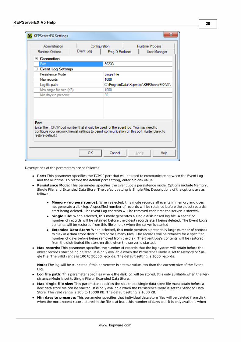
Descriptions of the parameters are as follows:
l Port: This parameter specifies the TCP/IP port that will be used to communicate between the Event Logand the Runtime. To restore the default port setting, enter a blank value.
l Persistence Mode: This parameter specifies the Event Log's persistence mode. Options include Memory,Single File, and Extended Data Store. The default setting is Single File. Descriptions of the options are asfollows:
l Memory (no persistence):When selected, this mode records all events in memory and doesnot generate a disk log. A specified number of records will be retained before the oldest recordsstart being deleted. The Event Log contents will be removed each time the server is started.
l Single File:When selected, this mode generates a single disk-based log file. A specifiednumber of records will be retained before the oldest records start being deleted. The Event Log'scontents will be restored from this file on disk when the server is started.
l Extended Data Store:When selected, this mode persists a potentially large number of recordsto disk in a data store distributed across many files. The records will be retained for a specifiednumber of days before being removed from the disk. The Event Log's contents will be restoredfrom the distributed file store on disk when the server is started.
l Max records: This parameter specifies the number of records that the log system will retain before theoldest records start being deleted. It is only available when the Persistence Mode is set to Memory or Sin-gle File. The valid range is 100 to 30000 records. The default setting is 1000 records.
Note: The log will be truncated if this parameter is set to a value less than the current size of the EventLog.
l Log file path: This parameter specifies where the disk log will be stored. It is only available when the Per-sistence Mode is set to Single File or Extended Data Store.
l Max single file size: This parameter specifies the size that a single data store file must attain before anew data store file can be started. It is only available when the Persistence Mode is set to Extended DataStore. The valid range is 100 to 10000 KB. The default setting is 1000 KB.
l Min days to preserve: This parameter specifies that individual data store files will be deleted from diskwhen the most recent record stored in the file is at least this number of days old. It is only available when
www. kepware.com
28
KEPServerEX V5 Help
the Persistence Mode is set to Extended Data Store. The valid range is 1 to 90 days. The default setting is30 days.
Note: The Event Log System would be useless if there was no mechanism to protect its contents. If operatorscould change these parameters or reset the log, the purpose would be lost. Utilize the User Manager to limit whatfunctions an operator can access.
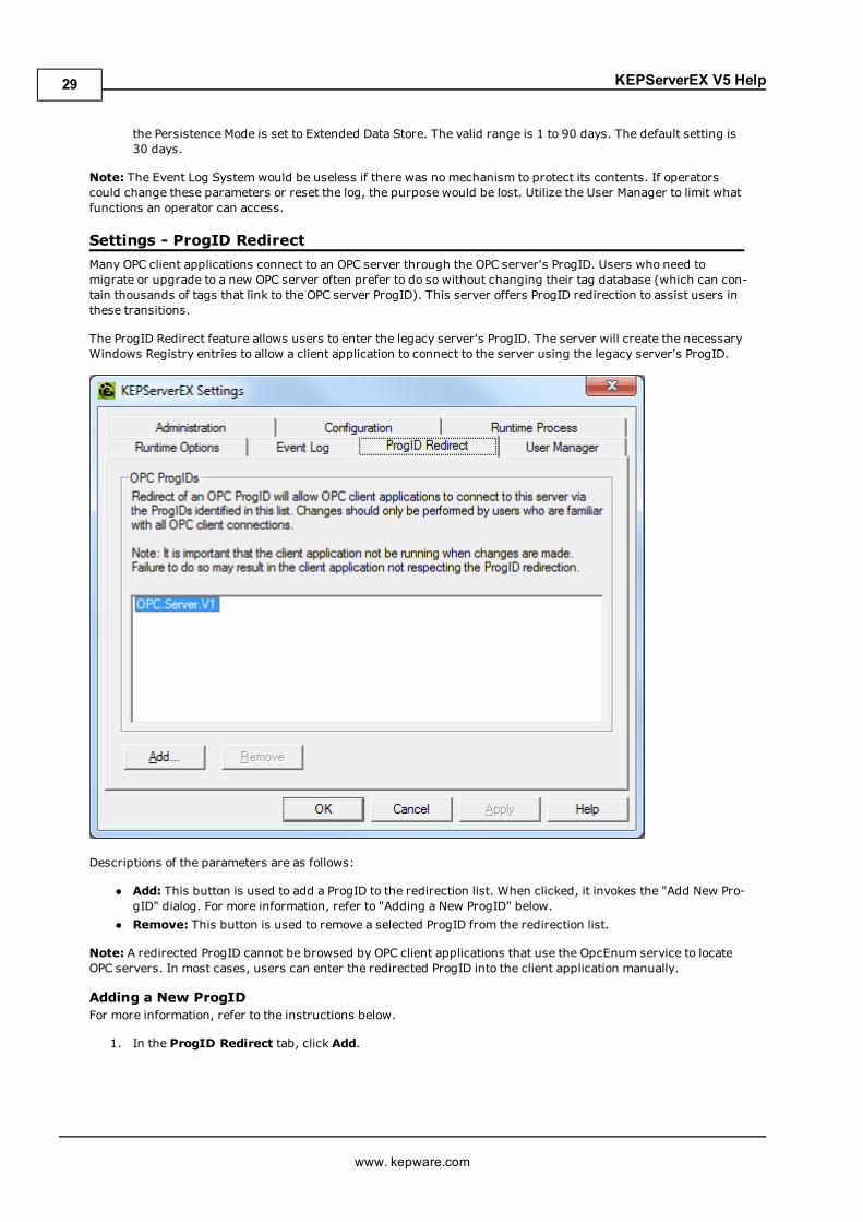
Settings - ProgID RedirectMany OPC client applications connect to an OPC server through the OPC server's ProgID. Users who need tomigrate or upgrade to a new OPC server often prefer to do so without changing their tag database (which can con-tain thousands of tags that link to the OPC server ProgID). This server offers ProgID redirection to assist users inthese transitions.
The ProgID Redirect feature allows users to enter the legacy server's ProgID. The server will create the necessaryWindows Registry entries to allow a client application to connect to the server using the legacy server's ProgID.
Descriptions of the parameters are as follows:
l Add: This button is used to add a ProgID to the redirection list. When clicked, it invokes the "Add New Pro-gID" dialog. For more information, refer to "Adding a New ProgID" below.
l Remove: This button is used to remove a selected ProgID from the redirection list.
Note: A redirected ProgID cannot be browsed by OPC client applications that use the OpcEnum service to locateOPC servers. In most cases, users can enter the redirected ProgID into the client application manually.
Adding a New ProgIDFor more information, refer to the instructions below.
1. In the ProgID Redirect tab, click Add.
www. kepware.com
29
KEPServerEX V5 Help
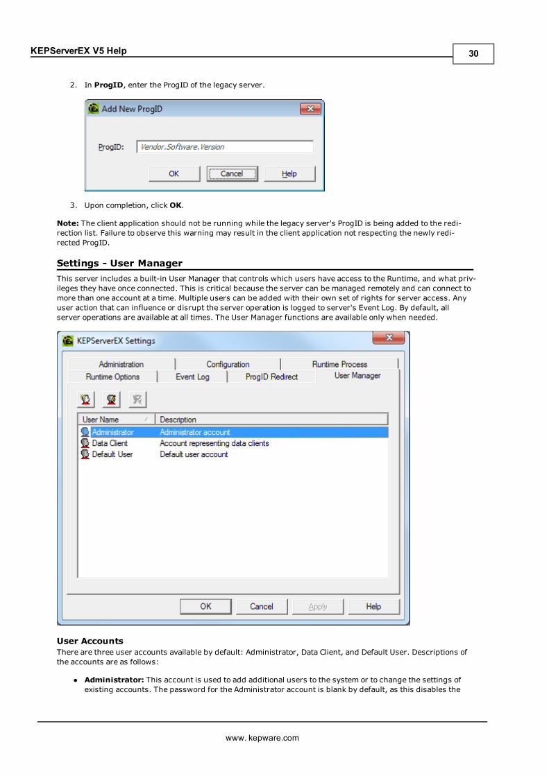
2. In ProgID, enter the ProgID of the legacy server.
3. Upon completion, clickOK.
Note: The client application should not be running while the legacy server's ProgID is being added to the redi-rection list. Failure to observe this warning may result in the client application not respecting the newly redi-rected ProgID.
Settings - User ManagerThis server includes a built-in User Manager that controls which users have access to the Runtime, and what priv-ileges they have once connected. This is critical because the server can be managed remotely and can connect tomore than one account at a time. Multiple users can be added with their own set of rights for server access. Anyuser action that can influence or disrupt the server operation is logged to server's Event Log. By default, allserver operations are available at all times. The User Manager functions are available only when needed.
User AccountsThere are three user accounts available by default: Administrator, Data Client, and Default User. Descriptions ofthe accounts are as follows:
l Administrator: This account is used to add additional users to the system or to change the settings ofexisting accounts. The password for the Administrator account is blank by default, as this disables the
www. kepware.com
30
KEPServerEX V5 Help
security settings for connecting the Configuration. Setting the password will enable the User ManagementSystem. The Administrator account cannot be deleted, but its password can be changed.
l Data Client: This account is used when an external data client attempts to perform an action that is gov-erned by access control. It supports standard privileges, and may also allow dynamic addressing andwrites to System Tags. It cannot have a password assigned to it, cannot be used for anonymous login viaOPC UA, and cannot be used to create a session from the server Configuration.
l Default User: This account is used when no other account is active, which is the normal condition of theserver. The Default User account cannot be deleted. It can only be disabled when the Administratordenies the Default User all privileges.
Adding and Editing User AccountsTo create additional user accounts, click theNew User icon. To edit existing user accounts, select the accountand then either double-click or press the Edit User icon. To delete a user account, select it and then press theDelete User icon.
Note: The User Properties dialog will depend on the selected user account. For more information, refer to the sub-topics below.
Administrator and Default User Properties
Descriptions of the parameters are as follows:
l Name: This parameter specifies a name for the user account. User names are case sensitive, and can beup to 31 characters in length.
l Description: This parameter allows a brief description of the user account. This can be particularly help-ful for ensuring that operators log in to the proper account.
l Assign/Change Password:When checked, this option enables the Password and Confirm fields.Description of the fields are as follows:
l Password: This field specifies the password that the user must enter in order to log into the sys-tem. The password can be up to 15 characters in length. It must be entered correctly in both thePassword and Confirm fields for the change to be accepted. Each time a user account is edited,the password must be re-entered. If the field is left blank, the password will be removed fromthe account.
l Confirm: This field confirms the password entered in the parameter above.
www. kepware.com
31
KEPServerEX V5 Help
l Edit Project:When checked, this option allows the user account to perform the specified tasks.l Modify Server Settings:When checked, this option allows the user account to modify server settings.l Disconnect Clients:When checked, this option allows the user account to disconnect clients.l Reset Event Log:When checked, this option allows the user account to reset the Event Log.l Manage OPC UA/.NET Configuration:When checked, this option allows the user account to managethe OPC UA/.NET configuration.
l Manage Licenses:When checked, this option allows the user account to manage licenses.
Note:When Login Mode is enabled, only the Administrator can access server-specific functions from the Admin-istration utility.
Data Client User Properties
Descriptions of the parameters are as follows:
l Name: This parameter specifies a name for the user account. User names are case sensitive, and can beup to 31 characters in length.
l Description: This parameter allows a brief description of the user account. This can be particularly help-ful for ensuring that operators log in to the proper account.
l Assign/Change Password:When checked, this option enables the Password and Confirm fields.Description of the fields are as follows:
l Password: This field specifies the password that the user must enter in order to log into the sys-tem. The password can be up to 15 characters in length. It must be entered correctly in both thePassword and Confirm fields for the change to be accepted. Each time a user account is edited,the password must be re-entered. If the field is left blank, the password will be removed fromthe account.
l Confirm: This field confirms the password entered in the parameter above.l Allow writes to system tags that:When checked, this option specifies when writes are allowed to sys-tem tags.
l Allow Dynamic Addressing:When checked, this option enables Dynamic Addressing.
www. kepware.com
32
KEPServerEX V5 Help
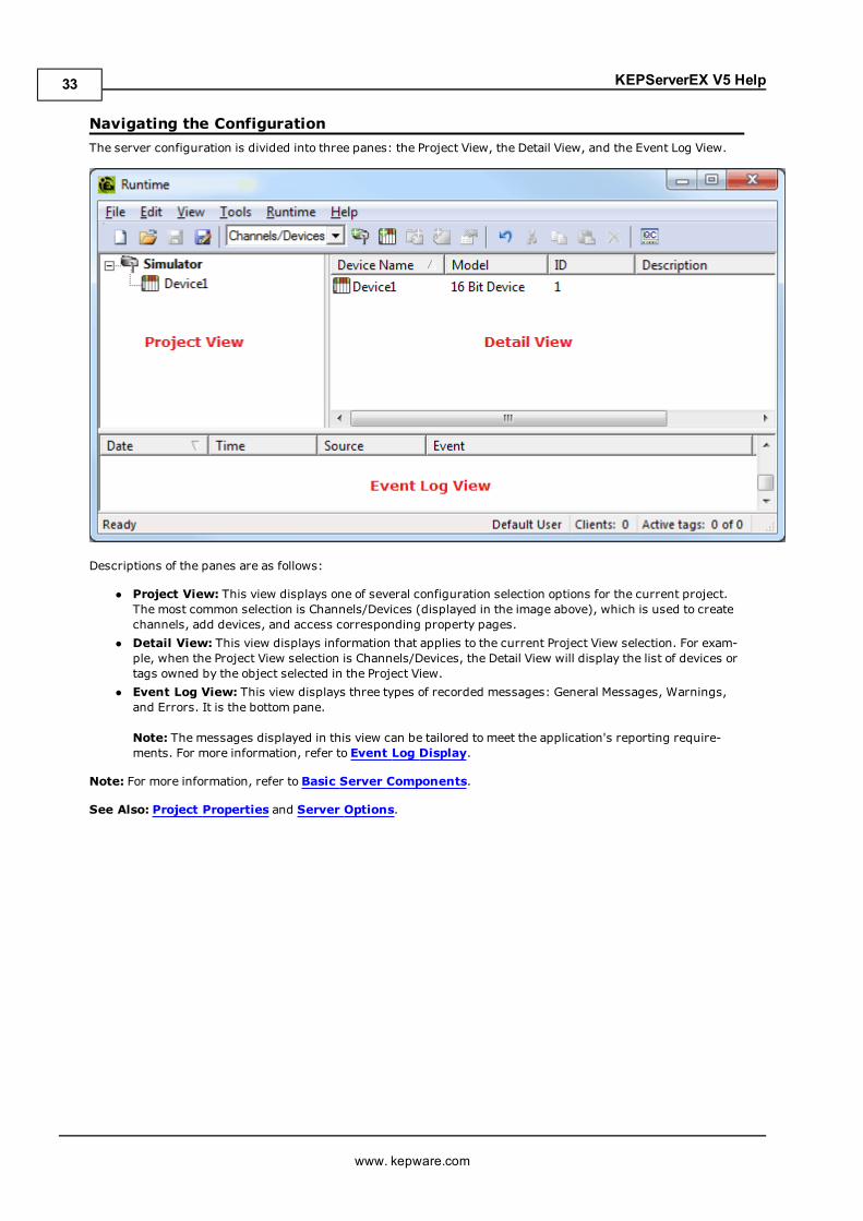
Navigating the ConfigurationThe server configuration is divided into three panes: the Project View, the Detail View, and the Event Log View.
Descriptions of the panes are as follows:
l Project View: This view displays one of several configuration selection options for the current project.The most common selection is Channels/Devices (displayed in the image above), which is used to createchannels, add devices, and access corresponding property pages.
l Detail View: This view displays information that applies to the current Project View selection. For exam-ple, when the Project View selection is Channels/Devices, the Detail View will display the list of devices ortags owned by the object selected in the Project View.
l Event Log View: This view displays three types of recorded messages: General Messages, Warnings,and Errors. It is the bottom pane.
Note: The messages displayed in this view can be tailored to meet the application's reporting require-ments. For more information, refer to Event Log Display.
Note: For more information, refer to Basic Server Components.
See Also: Project Properties and Server Options.
www. kepware.com
33
KEPServerEX V5 Help
Project PropertiesTo access the Project Properties tabs from the configuration, click File | Project Properties. For more infor-mation, select a link from the list below.
Project Properties - IdentificationProject Properties - OPC DA SettingsProject Properties - OPC DA ComplianceProject Properties - DDEProject Properties - FastDDE/SuiteLinkProject Properties - iFIX PDB SettingsProject Properties - OPC UAProject Properties - OPC AEProject Properties - OPC .NET
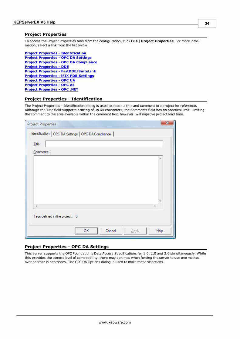
Project Properties - IdentificationThe Project Properties - Identification dialog is used to attach a title and comment to a project for reference.Although the Title field supports a string of up 64 characters, the Comments field has no practical limit. Limitingthe comment to the area available within the comment box, however, will improve project load time.
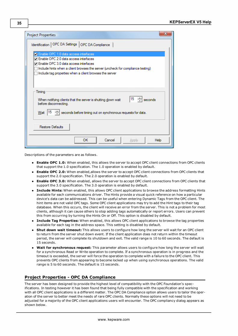
Project Properties - OPC DA SettingsThis server supports the OPC Foundation's Data Access Specifications for 1.0, 2.0 and 3.0 simultaneously. Whilethis provides the utmost level of compatibility, there may be times when forcing the server to use one methodover another is necessary. The OPC DA Options dialog is used to make these selections.
www. kepware.com
34
KEPServerEX V5 Help
Descriptions of the parameters are as follows.
l Enable OPC 1.0: When enabled, this allows the server to accept OPC client connections from OPC clientsthat support the 1.0 specification. The 1.0 operation is enabled by default.
l Enable OPC 2.0:When enabled,allows the server to accept OPC client connections from OPC clients thatsupport the 2.0 specification. The 2.0 operation is enabled by default.
l Enable OPC 3.0: When enabled, allows the server to accept OPC client connections from OPC clients thatsupport the 3.0 specification. The 3.0 operation is enabled by default.
l Include Hints: When enabled, this allows OPC client applications to browse the address formatting Hintsavailable for each communications driver. The Hints provide a visual quick reference on how a particulardevice's data can be addressed. This can be useful when entering Dynamic Tags from the OPC client. Thehint items are not valid OPC tags. Some OPC client applications may try to add the Hint tags to their tagdatabase. When this occurs, the client will receive an error from the server. This is not a problem for mostclients, although it can cause others to stop adding tags automatically or report errors. Users can preventthis from occurring by turning the Hints On or Off. This option is disabled by default.
l Include Tag Properties:When enabled, this allows OPC client applications to browse the tag propertiesavailable for each tag in the address space. This setting is disabled by default.
l Shut down wait timeout: This allows users to configure how long the server will wait for an OPC clientto return from the server shut down event. If the client application does not return within the timeoutperiod, the server will complete its shutdown and exit. The valid range is 10 to 60 seconds. The default is15 seconds.
l Wait for synchronous request: This parameter allows users to configure how long the server will waitfor a synchronous Read or Write operation to complete. If a synchronous operation is in progress and thetimeout is exceeded, the server will force the operation to complete with a failure to the OPC client. Thisprevents OPC clients from appearing to become locked up when using synchronous operations. The validrange is 5 to 60 seconds. The default is 15 seconds.
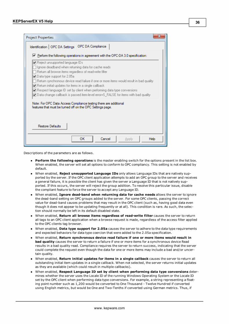
Project Properties - OPC DA ComplianceThe server has been designed to provide the highest level of compatibility with the OPC Foundation's spec-ifications. In testing however it has been found that being fully compatible with the specification and workingwith all OPC client applications is a different matter. The OPC DA Compliance option allows users to tailor the oper-ation of the server to better meet the needs of rare OPC clients. Normally these options will not need to beadjusted for a majority of the OPC client applications users will encounter. The OPC compliancy dialog appears asshown below.
www. kepware.com
35
KEPServerEX V5 Help
Descriptions of the parameters are as follows.
l Perform the following operations is the master enabling switch for the options present in the list box.When enabled, the server will set all options to conform to OPC compliancy. This setting is not enabled bydefault.
l When enabled, Reject unsupported Language IDs only allows Language IDs that are natively sup-ported by the server. If the OPC client application attempts to add an OPC group to the server and receivesa general failure, it is possible the client has given the server a Language ID that is not natively sup-ported. If this occurs, the server will reject the group addition. To resolve this particular issue, disablethe compliant feature to force the server to accept any Language ID.
l When enabled, Ignore dead-band when returning data for cache needs allows the server to ignorethe dead-band setting on OPC groups added to the server. For some OPC clients, passing the correctvalue for dead-band causes problems that may result in the OPC client (such as, having good data eventhough it does not appear to be updating frequently or at all). This condition is rare. As such, the selec-tion should normally be left in its default disabled state.
l When enabled, Return all browse items regardless of read-write filter causes the server to returnall tags to an OPC client application when a browse request is made, regardless of the access filter appliedto the OPC clients tag browser.
l When enabled, Data type support for 2.05a causes the server to adhere to the data type requirementsand expected behaviors for data type coercion that were added to the 2.05a specification.
l When enabled, Return synchronous device read failure if one or more items would result inbad quality causes the server to return a failure if one or more items for a synchronous device Readresults in a bad quality read. Compliance requires the server to return success, indicating that the servercould complete the request even though the data for one or more items may include a bad and/or uncer-tain quality.
l When enabled, Return initial updates for items in a single callback causes the server to return alloutstanding initial item updates in a single callback. When not selected, the server returns initial updatesas they are available (which could result in multiple callbacks).
l When enabled, Respect Language ID set by client when performing data type conversions deter-mines whether the server uses the Locale ID of the running Windows Operating System or the Locale IDset by the OPC client when performing data type conversions. For example, a string representing a float-ing point number such as 1,200 would be converted to One Thousand - Twelve Hundred if convertedusing English metrics, but would be One and Two-Tenths if converted using German metrics. Thus, if
www. kepware.com
36
KEPServerEX V5 Help
German software is running on an English OS, users need to determine how the comma will be handled.This setting allows for such flexibility. By default, and due to historical implementation, the serverrespects the Locale ID of the operating system.
l When enabled, Data change callback is passed item-level error=S_FALSE for items with badquality causes the server to return S_FALSE in the item error array for items without good quality. Thissetting will default to True for existing projects that are set to full compliance, and False for those that arenot. When set to False, the legacy behavior of returning E_FAIL (0x80004005) will occur.
Project Properties - DDEWhile the server is first and foremost an OPC server, there are still a number of applications that requireDynamic Data Exchange (DDE) to share data. The server provides access to DDE applications that supportone of the following DDE formats: CF_Text, XL_Table and Advanced DDE. CF_Text and XL_Table are standardDDE formats developed by Microsoft for use with all DDE aware applications. Advanced DDE is a high per-formance format supported by a number of client applications specific to the industrial market.
Important: In order for the DDE interface to connect with the server, the Runtime must be allowed to interactwith the desktop. For more information, refer toHow To... Allow Desktop Interactions.
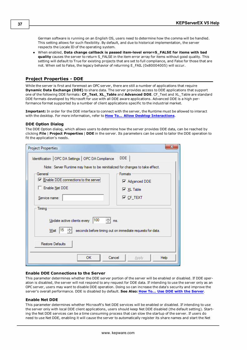
DDE Option DialogThe DDE Option dialog, which allows users to determine how the server provides DDE data, can be reached byclicking File | Project Properties | DDE in the server. Its parameters can be used to tailor the DDE operation tofit the application's needs.
Enable DDE Connections to the ServerThis parameter determines whether the DDE server portion of the server will be enabled or disabled. If DDE oper-ation is disabled, the server will not respond to any request for DDE data. If intending to use the server only as anOPC server, users may want to disable DDE operation. Doing so can increase the data's security and improve theserver's overall performance. DDE is disabled by default. See Also: How To... Use DDE with the Server.
Enable Net DDEThis parameter determines whether Microsoft's Net DDE services will be enabled or disabled. If intending to usethe server only with local DDE client applications, users should keep Net DDE disabled (the default setting). Start-ing the Net DDE services can be a time consuming process that can slow the startup of the server. If users doneed to use Net DDE, enabling it will cause the server to automatically register its share names and start the Net
www. kepware.com
37
KEPServerEX V5 Help
DDE service manager. DDE shares will be removed when the server shuts down. See Also: How To... Use NetDDE with the Server.
Service NameThis parameter allows users to change how the server appears as an application name to DDE clients. This namewill initially be set to allow compatibility with the previous versions of the server. If users need to replace an exist-ing DDE server however, the server's service name can be changed to match the DDE server being replaced. Theservice name allows a string of 1 to 32 characters to be entered.
FormatsThis parameter allows users to configure the format of DDE to provide to client applications. All three formats areenabled by default. This is particularly useful when users experience problems connecting a DDE client appli-cation to the server: each of the DDE formats can be disabled in order to isolate a specific format for testing pur-poses.
Note: Every DDE aware application must support CF_Text at a minimum.
Update active clientsThis interval setting is used to batch up DDE data so that it can be transferred to client applications. When usinga DDE format performance gains only come when large blocks of server data can be sent in a single DDEresponse. To improve the ability of the server to gather a large block of data, the update timer can be set to allowa pool of new data to accumulate before a being sent to a client application. The valid range of the update timer is20-60000 milliseconds. The default is 100 milliseconds.
WaitThis parameter is used to configure a timeout for the completion of DDE request. If a DDE client request (either aRead or Write operation) on the server cannot be completed within the specified timeout, an error will bereturned to the DDE Client. The valid range is 1-30 seconds. The default is 15 seconds.
Note: Server Runtime may have to be reinitialized for changes to take effect.
Project Properties - FastDDE/SuitelinkThe server's support of Wonderware Corporation's FastDDE and SuiteLink simplifies the task of connecting theserver with FactorySuite applications. The Wonderware connectivity toolkit is used to simultaneously provide OPCand FastDDE/SuiteLink connectivity while allowing for quick access to device data without the use of intermediarybridging software.
Important: In order for the FastDDE interface to connect with the server, the Runtime must be allowed to inter-act with the desktop. For more information, refer toHow To... Allow Desktop Interactions.
Note: For proper FastDDE/SuiteLink operation (and for this tab to be displayed in Project Properties), the Won-derware FS2000 Common Components (or the InTouch Runtime Component version 8.0 or higher) must beinstalled on the PC.
www. kepware.com
38
KEPServerEX V5 Help
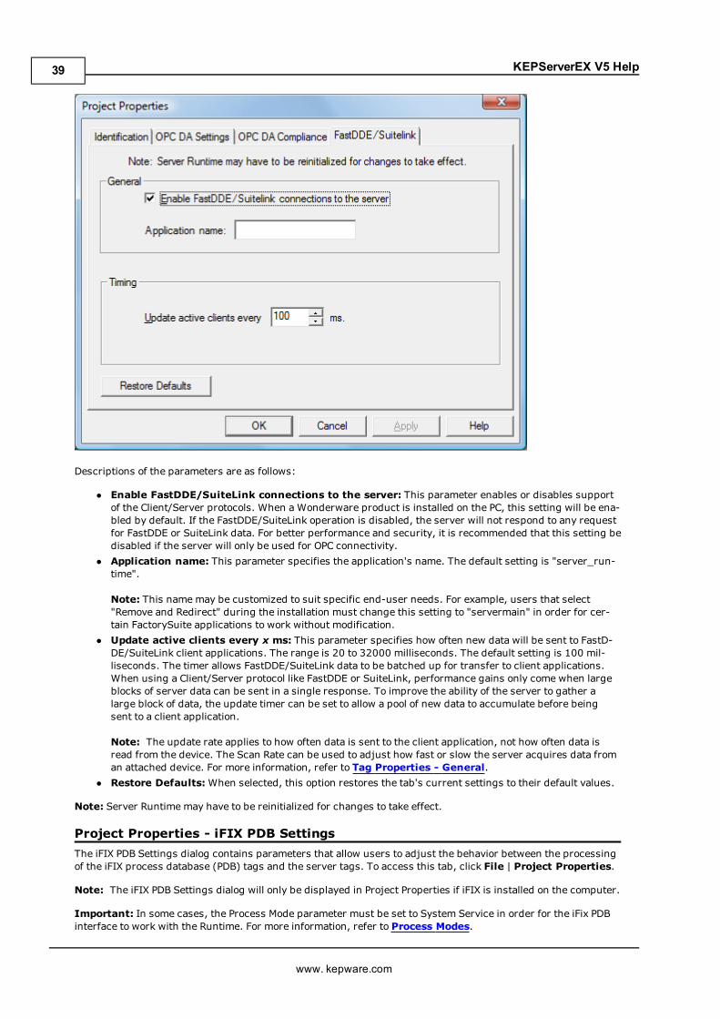
Descriptions of the parameters are as follows:
l Enable FastDDE/SuiteLink connections to the server: This parameter enables or disables supportof the Client/Server protocols. When a Wonderware product is installed on the PC, this setting will be ena-bled by default. If the FastDDE/SuiteLink operation is disabled, the server will not respond to any requestfor FastDDE or SuiteLink data. For better performance and security, it is recommended that this setting bedisabled if the server will only be used for OPC connectivity.
l Application name: This parameter specifies the application's name. The default setting is "server_run-time".
Note: This namemay be customized to suit specific end-user needs. For example, users that select"Remove and Redirect" during the installation must change this setting to "servermain" in order for cer-tain FactorySuite applications to work without modification.
l Update active clients every x ms: This parameter specifies how often new data will be sent to FastD-DE/SuiteLink client applications. The range is 20 to 32000 milliseconds. The default setting is 100 mil-liseconds. The timer allows FastDDE/SuiteLink data to be batched up for transfer to client applications.When using a Client/Server protocol like FastDDE or SuiteLink, performance gains only come when largeblocks of server data can be sent in a single response. To improve the ability of the server to gather alarge block of data, the update timer can be set to allow a pool of new data to accumulate before beingsent to a client application.
Note: The update rate applies to how often data is sent to the client application, not how often data isread from the device. The Scan Rate can be used to adjust how fast or slow the server acquires data froman attached device. For more information, refer to Tag Properties - General.
l Restore Defaults:When selected, this option restores the tab's current settings to their default values.
Note: Server Runtime may have to be reinitialized for changes to take effect.
Project Properties - iFIX PDB SettingsThe iFIX PDB Settings dialog contains parameters that allow users to adjust the behavior between the processingof the iFIX process database (PDB) tags and the server tags. To access this tab, click File | Project Properties.
Note: The iFIX PDB Settings dialog will only be displayed in Project Properties if iFIX is installed on the computer.
Important: In some cases, the Process Mode parameter must be set to System Service in order for the iFix PDBinterface to work with the Runtime. For more information, refer to Process Modes.
www. kepware.com
39
KEPServerEX V5 Help
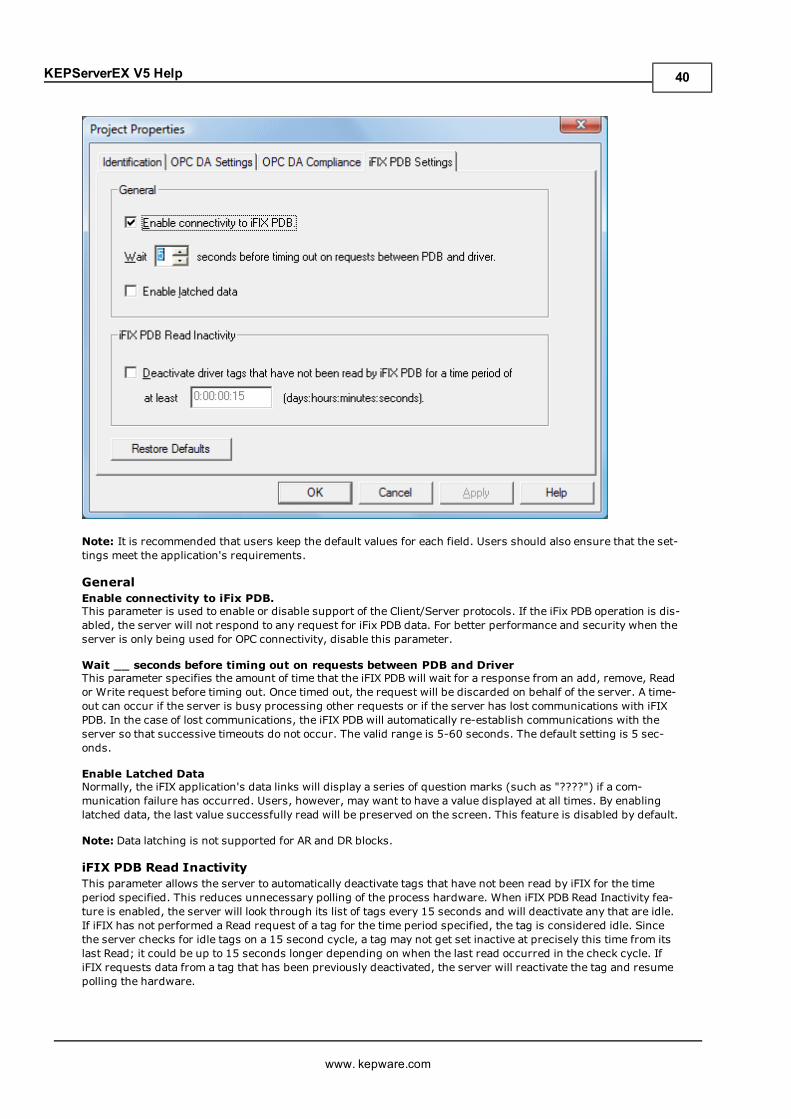
Note: It is recommended that users keep the default values for each field. Users should also ensure that the set-tings meet the application's requirements.
GeneralEnable connectivity to iFix PDB.This parameter is used to enable or disable support of the Client/Server protocols. If the iFix PDB operation is dis-abled, the server will not respond to any request for iFix PDB data. For better performance and security when theserver is only being used for OPC connectivity, disable this parameter.
Wait __ seconds before timing out on requests between PDB and DriverThis parameter specifies the amount of time that the iFIX PDB will wait for a response from an add, remove, Reador Write request before timing out. Once timed out, the request will be discarded on behalf of the server. A time-out can occur if the server is busy processing other requests or if the server has lost communications with iFIXPDB. In the case of lost communications, the iFIX PDB will automatically re-establish communications with theserver so that successive timeouts do not occur. The valid range is 5-60 seconds. The default setting is 5 sec-onds.
Enable Latched DataNormally, the iFIX application's data links will display a series of question marks (such as "????") if a com-munication failure has occurred. Users, however, may want to have a value displayed at all times. By enablinglatched data, the last value successfully read will be preserved on the screen. This feature is disabled by default.
Note: Data latching is not supported for AR and DR blocks.
iFIX PDB Read InactivityThis parameter allows the server to automatically deactivate tags that have not been read by iFIX for the timeperiod specified. This reduces unnecessary polling of the process hardware. When iFIX PDB Read Inactivity fea-ture is enabled, the server will look through its list of tags every 15 seconds and will deactivate any that are idle.If iFIX has not performed a Read request of a tag for the time period specified, the tag is considered idle. Sincethe server checks for idle tags on a 15 second cycle, a tag may not get set inactive at precisely this time from itslast Read; it could be up to 15 seconds longer depending on when the last read occurred in the check cycle. IfiFIX requests data from a tag that has been previously deactivated, the server will reactivate the tag and resumepolling the hardware.
www. kepware.com
40
KEPServerEX V5 Help
This feature is disabled by default upon driver install. Once this feature is enabled, however, it becomes appliedto all projects. Users may specify an idle time of up to 6:23:59:59 (1 week).
Caution: This feature is meant to be used with Register Tags only and can cause non-register tags to go offscan. To avoid this situation when using this feature, be sure to set the inactivity timer greater than the longestscan time configured in the iFIX database.
Format Range Default Value[days:hours:minutes:seconds] 0:00:00:15 to 6:23:59:59 0:00:00:15 (15 seconds)
Note: The time period can also be specified in seconds. For example, if 62 is entered, the page will show0:00:01:02 when accessed next.
Examples
Time Format20 seconds 0:00:00:20 or 201 minute 0:00:01:00 or 601 hour and 30 minutes 0:01:30:00 or 54002 days 2:00:00:00
Restore DefaultsThis parameter restores the tab's current settings to their default values.
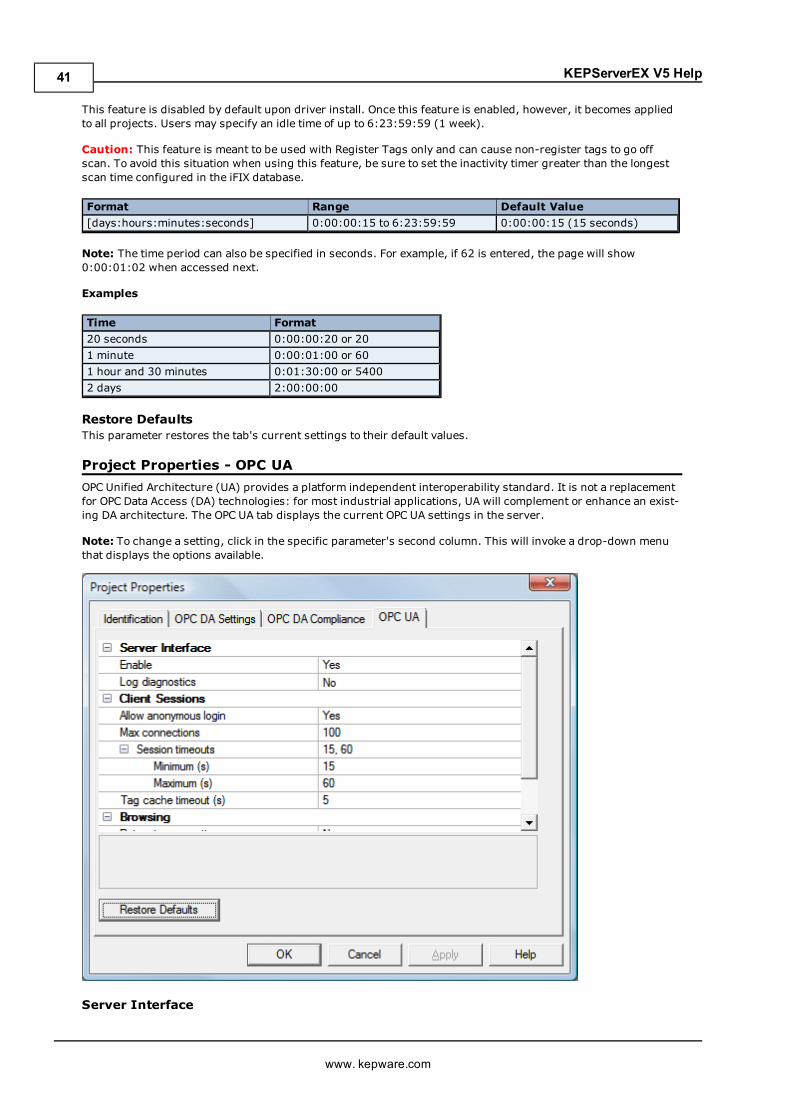
Project Properties - OPC UAOPC Unified Architecture (UA) provides a platform independent interoperability standard. It is not a replacementfor OPC Data Access (DA) technologies: for most industrial applications, UA will complement or enhance an exist-ing DA architecture. The OPC UA tab displays the current OPC UA settings in the server.
Note: To change a setting, click in the specific parameter's second column. This will invoke a drop-down menuthat displays the options available.
Server Interface
www. kepware.com
41
KEPServerEX V5 Help
Descriptions of the parameters are as follows:
l Enable:When enabled, the UA server interface will be initialized and accept client connections. When dis-abled, the remaining parameters on this page will also be disabled.
l Log Diagnostics: When enabled, OPC UA stack diagnostics will be logged to the Event Log. This shouldonly be enabled for debugging purposes.
Client SessionsDescriptions of the parameters are as follows:
l Allow Anonymous Login:When disabled, this parameter specifies that user name and password infor-mation will be required to establish a connection. The default setting is enabled.
Note: If this setting is disabled, users cannot login as the Default User in the User Manager. Users canlogin as the Administrator provided that a password is set in the User Manager and is used to login.
l Max Connections: This parameter specifies the maximum number of supported connections. The validrange is 1 to 100. The default setting is 100.
l Session Timeouts: This parameter specifies the UA client's timeout limit for establishing a session.Values may be changed depending on the needs of the application. The default values are 15 to 60 sec-onds.
l Minimum: This parameter specifies the UA client's minimum timeout limit. The default setting is15 seconds.
l Maximum: This parameter specifies the UA client's maximum timeout limit. The default settingis 60 seconds.
l Tag cache timeout: This parameter specifies the tag cache timeout. The valid range is 0 to 60 seconds.The default setting is 5 seconds.
Note: This timeout controls how long a tag will be cached after a UA client is done using it. In caseswhere UA clients Read/Write to unregistered tags at a set interval, users can improve performance byincreasing the timeout. For example, if a client is reading an unregistered tag every 5 seconds, the tagcache timeout should be set to 6 seconds. Since the tag will not have to be recreated during each clientrequest, performance will improve.
BrowsingDescriptions of the parameters are as follows:
l Return Tag Properties: When enabled, this parameter allows UA client applications to browse the tagproperties available for each tag in the address space. This setting is disabled by default.
l Return Address Hints: When enabled, this parameter allows UA client applications to browse theaddress formatting hints available for each item. Although the hints are not valid UA tags, certain UAclient applications may try to add them to the tag database. When this occurs, the client will receive anerror from the server. This may cause the client to report errors or stop adding the tags automatically. Toprevent this from occurring, make sure that this parameter is disabled. This setting is disabled bydefault.
Monitored ItemsDescription of the parameter is as follows:
l Max Data Queue Size: This parameter specifies the maximum number of data notifications that will bequeued for an item. The valid range is 1 to 100. The default setting is 2.
Note: The data queue is used when the monitored item's update rate is faster than the subscription's pub-lish rate. For example, if the monitored item update rate is 1 second, and a subscription publishes every10 seconds, then 10 data notifications will be published for the item every 10 seconds. Because queuingdata consumes memory, this value should be limited when memory is a concern.
SubscriptionsDescriptions of the parameters are as follows:
l Max Retransmit Queue Size: This parameter specifies the maximum number of publishes that will bequeued per subscription. The valid range is 1 to 100. A value of zero will disable retransmits. The defaultsetting is 0.
www. kepware.com
42
KEPServerEX V5 Help
Note: Subscription publish events are queued and retransmitted at the client's request. Because queuingconsumes memory, this value should be limited when memory is a concern.
l Max Notifications Per Publish: This parameter specifies the maximum number of notifications per pub-lish. The valid range is 1 to 65536. The default setting is 65536.
Note: This value may affect the connection's performance by limiting the size of the packets sent from theserver to the client. In general, large values should be used for high bandwidth connections, and smallvalues should be used for low bandwidth connections.
Note: For more information on OPC UA, refer to the OPC UA Configuration Manager help file.
Project Properties - OPC AEEvents are used to signal an occurrence in the server and are similar to data updates in OPC Data Access. TheOPC AE functionality allows users to receive Simple Events from the server, including system startup and shut-down messages, warnings, errors and so forth. These events are then displayed in the Event Log.
The OPC AE tab is used to specify a number of project-level AE settings. Changes made to these settings will takeeffect after all A&E clients disconnect from the server.
Descriptions of the parameters are as follows:
l Enable AE Connections to the Server: This parameter turns the OPC AE server on and off.l Enable Simple Events:When checked, simple events will be made available to clients. Whenunchecked, the events will be sent. The default setting is checked.
l Max Subscription Buffer Size: This parameter specifies the maximum number of events that the A&EPlug-In will send to a client in one send call. The range is 0 to 65534. The default setting is 100. 0 meansthere is no limit.
l Min Subscription Buffer Time: This parameter specifies the minimum time between send calls to aclient. The supported range is 1000-60000ms. The default setting is 1000ms.
l Min Keep-Alive Time: This parameter specifies the minimum amount of time between keep-alive mes-sages sent from the server to the client. The default setting is 1000ms.
l Restore Defaults: This parameter restores the tab's current settings to their default values.
www. kepware.com
43
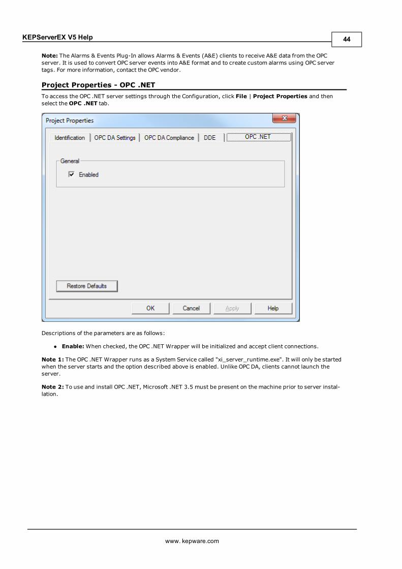
KEPServerEX V5 Help
Note: The Alarms & Events Plug-In allows Alarms & Events (A&E) clients to receive A&E data from the OPCserver. It is used to convert OPC server events into A&E format and to create custom alarms using OPC servertags. For more information, contact the OPC vendor.
Project Properties - OPC .NETTo access the OPC .NET server settings through the Configuration, click File | Project Properties and thenselect theOPC .NET tab.
Descriptions of the parameters are as follows:
l Enable:When checked, the OPC .NET Wrapper will be initialized and accept client connections.
Note 1: The OPC .NET Wrapper runs as a System Service called "xi_server_runtime.exe". It will only be startedwhen the server starts and the option described above is enabled. Unlike OPC DA, clients cannot launch theserver.
Note 2: To use and install OPC .NET, Microsoft .NET 3.5 must be present on the machine prior to server instal-lation.
www. kepware.com
44
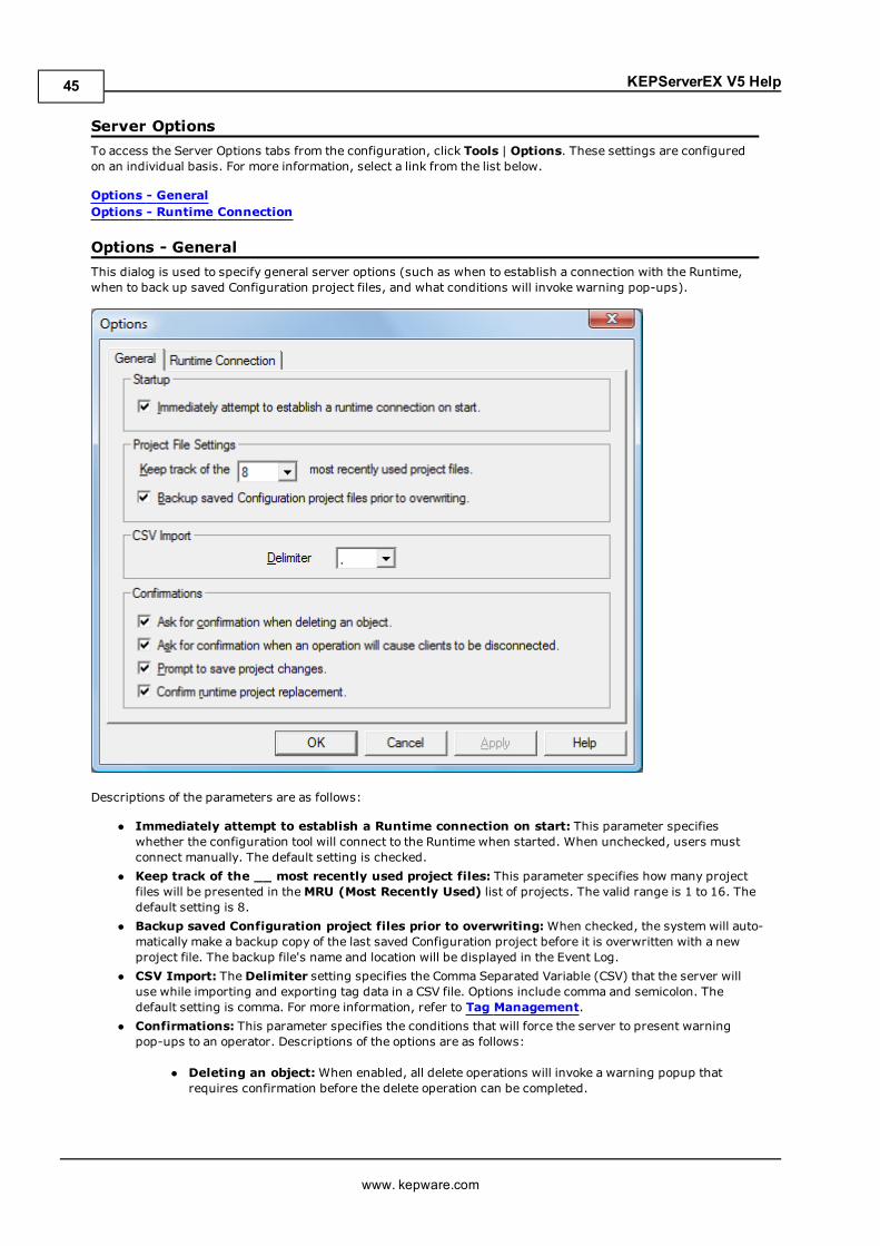
KEPServerEX V5 Help
Server OptionsTo access the Server Options tabs from the configuration, click Tools | Options. These settings are configuredon an individual basis. For more information, select a link from the list below.
Options - GeneralOptions - Runtime Connection
Options - GeneralThis dialog is used to specify general server options (such as when to establish a connection with the Runtime,when to back up saved Configuration project files, and what conditions will invoke warning pop-ups).
Descriptions of the parameters are as follows:
l Immediately attempt to establish a Runtime connection on start: This parameter specifieswhether the configuration tool will connect to the Runtime when started. When unchecked, users mustconnect manually. The default setting is checked.
l Keep track of the __ most recently used project files: This parameter specifies how many projectfiles will be presented in theMRU (Most Recently Used) list of projects. The valid range is 1 to 16. Thedefault setting is 8.
l Backup saved Configuration project files prior to overwriting:When checked, the system will auto-matically make a backup copy of the last saved Configuration project before it is overwritten with a newproject file. The backup file's name and location will be displayed in the Event Log.
l CSV Import: TheDelimiter setting specifies the Comma Separated Variable (CSV) that the server willuse while importing and exporting tag data in a CSV file. Options include comma and semicolon. Thedefault setting is comma. For more information, refer to Tag Management.
l Confirmations: This parameter specifies the conditions that will force the server to present warningpop-ups to an operator. Descriptions of the options are as follows:
l Deleting an object:When enabled, all delete operations will invoke a warning popup thatrequires confirmation before the delete operation can be completed.
www. kepware.com
45
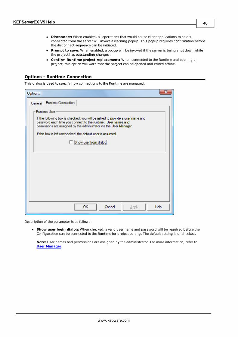
KEPServerEX V5 Help
l Disconnect:When enabled, all operations that would cause client applications to be dis-connected from the server will invoke a warning popup. This popup requires confirmation beforethe disconnect sequence can be initiated.
l Prompt to save:When enabled, a popup will be invoked if the server is being shut down whilethe project has outstanding changes.
l Confirm Runtime project replacement: When connected to the Runtime and opening aproject, this option will warn that the project can be opened and edited offline.
Options - Runtime ConnectionThis dialog is used to specify how connections to the Runtime are managed.
Description of the parameter is as follows:
l Show user login dialog:When checked, a valid user name and password will be required before theConfiguration can be connected to the Runtime for project editing. The default setting is unchecked.
Note: User names and permissions are assigned by the administrator. For more information, refer toUser Manager.
www. kepware.com
46
KEPServerEX V5 Help
Basic Server ComponentsFor more information on a specific server component, select a link from the list below.
What is a Channel?What is a Device?What is a Tag?What is a Tag Group?What is the Alias Map?What is the Event Log?
What is a Channel?A channel represents a communication medium from the PC to one or more external devices. A channel can beused to represent a serial port, a card installed in the PC or an Ethernet socket.
Before adding devices to a project, users must define the channel that will be used when communicating withdevices. A channel and a device driver are closely tied. After creating a channel, only devices that the selecteddriver supports can be added to this channel.
Adding a ChannelChannels are added using the Channel Wizard, which guide users through the channel definition process. Tostart, users will be prompted for a logical name to assign the channel. This namemust be unique among all chan-nels and devices defined in the project. For information on reserved characters, refer toHow To... ProperlyName a Channel, Device, Tag, and Tag Group.
Next, users will be prompted for the device driver that will be used. A list box is presented that displays all of thedevice drivers currently installed in the system. All serial drivers can be used with multiple channels in the sameproject.
Note: For hardware card drivers, refer to the driver's help documentation the determine the ability to use withmultiple channels in a single project. For information on how to determine the number of supported channels,refer to Server Summary Information.
Users will then be prompted for the specific communication parameters to be used. Multiple channels cannotshare identical communication parameters; for example, two serial drivers cannot use COM1. For the correct com-munication parameters of a particular device, refer to both the manufacturer's and the driver's help doc-umentation.
Note: Flow Control settings for serial drivers are primarily used when connecting RS422/485 network devices tothe RS232 serial port via a converter. Most RS232 to RS422/485 converters require either no flow control (None)or that the RTS line be on when the PC is transmitting and off when listening (RTS).
The Channel Wizard will finish with a summary of the new channel.
Removing a ChannelTo remove a channel from the project, select the desired channel and then press the Delete key. Alternatively,select Edit | Delete from the Edit menu or toolbar.
Displaying Channel PropertiesTo display the Channel Properties of a specific channel, select the channel and then click Edit | Properties fromthe Edit menu or toolbar.
See Also: Channel Properties - General
Channel Properties - GeneralEach protocol or driver used in a server project is called a channel, which refers to a specific communicationsdriver. A server project can consist of many channels that have unique communications drivers or with the samecommunications driver.
In a server application, every channel namemust be unique. Although names can be up to 256 characters long,some OPC client applications may have a limited display window when browsing the tag space of an OPC server.The channel name entered will be part of the OPC browser information. For information on reserved characters,refer toHow To... Properly Name a Channel, Device, Tag, and Tag Group.
www. kepware.com
47
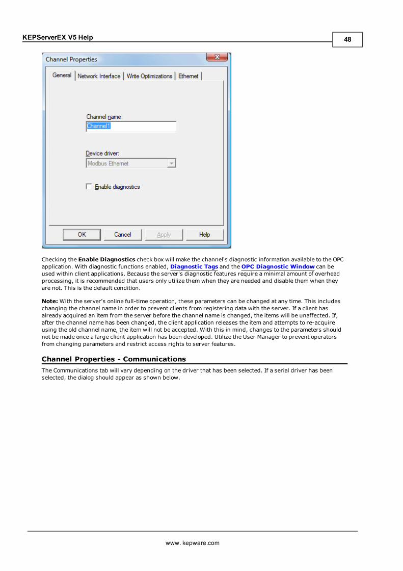
KEPServerEX V5 Help
Checking the Enable Diagnostics check box will make the channel's diagnostic information available to the OPCapplication. With diagnostic functions enabled, Diagnostic Tags and theOPC Diagnostic Window can beused within client applications. Because the server's diagnostic features require a minimal amount of overheadprocessing, it is recommended that users only utilize them when they are needed and disable them when theyare not. This is the default condition.
Note:With the server's online full-time operation, these parameters can be changed at any time. This includeschanging the channel name in order to prevent clients from registering data with the server. If a client hasalready acquired an item from the server before the channel name is changed, the items will be unaffected. If,after the channel name has been changed, the client application releases the item and attempts to re-acquireusing the old channel name, the item will not be accepted. With this in mind, changes to the parameters shouldnot be made once a large client application has been developed. Utilize the User Manager to prevent operatorsfrom changing parameters and restrict access rights to server features.
Channel Properties - CommunicationsThe Communications tab will vary depending on the driver that has been selected. If a serial driver has beenselected, the dialog should appear as shown below.
www. kepware.com
48
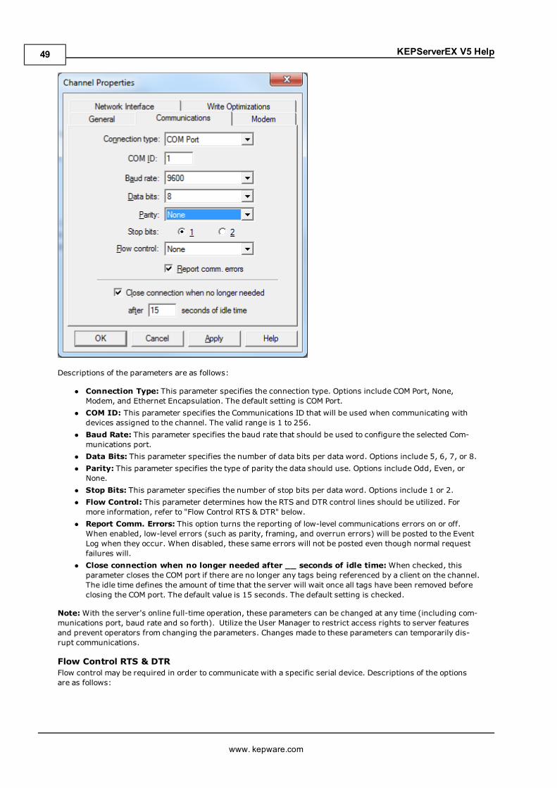
KEPServerEX V5 Help
Descriptions of the parameters are as follows:
l Connection Type: This parameter specifies the connection type. Options include COM Port, None,Modem, and Ethernet Encapsulation. The default setting is COM Port.
l COM ID: This parameter specifies the Communications ID that will be used when communicating withdevices assigned to the channel. The valid range is 1 to 256.
l Baud Rate: This parameter specifies the baud rate that should be used to configure the selected Com-munications port.
l Data Bits: This parameter specifies the number of data bits per data word. Options include 5, 6, 7, or 8.l Parity: This parameter specifies the type of parity the data should use. Options include Odd, Even, orNone.
l Stop Bits: This parameter specifies the number of stop bits per data word. Options include 1 or 2.l Flow Control: This parameter determines how the RTS and DTR control lines should be utilized. Formore information, refer to "Flow Control RTS & DTR" below.
l Report Comm. Errors: This option turns the reporting of low-level communications errors on or off.When enabled, low-level errors (such as parity, framing, and overrun errors) will be posted to the EventLog when they occur. When disabled, these same errors will not be posted even though normal requestfailures will.
l Close connection when no longer needed after __ seconds of idle time:When checked, thisparameter closes the COM port if there are no longer any tags being referenced by a client on the channel.The idle time defines the amount of time that the server will wait once all tags have been removed beforeclosing the COM port. The default value is 15 seconds. The default setting is checked.
Note:With the server's online full-time operation, these parameters can be changed at any time (including com-munications port, baud rate and so forth). Utilize the User Manager to restrict access rights to server featuresand prevent operators from changing the parameters. Changes made to these parameters can temporarily dis-rupt communications.
Flow Control RTS & DTRFlow control may be required in order to communicate with a specific serial device. Descriptions of the optionsare as follows:
www. kepware.com
49
KEPServerEX V5 Help
l None: This option does not toggle or assert control lines.l DTR: This option asserts the DTR line when the communications port is opened and remains on.l RTS: This option specifies that the RTS line will be high if bytes are available for transmission. After allbuffered bytes have been sent, the RTS line will be low. This is normally used with RS232/RS485 con-verter hardware.
l RTS, DTR: This option is a combination of DTR and RTS as described above.l RTS Always: This option asserts the RTS line when the communication port is opened and remains on.l RTS Manual: This option asserts the RTS line based on the timing parameters entered for Manual RTSControl.
Note:When using 2 wire RS485, "echoes" may occur on the communication lines. Since this communicationserver's serial drivers do not support echo suppression, it is recommended that the proper RS-485 converter beused in order to avoid issues with echo.
Channel Properties - Network InterfaceWith Ethernet Encapsulation, virtually all drivers currently available support some form of Ethernet com-munications. Some form of a network interface will be used, whether for a natively Ethernet-based driver or aserial driver configured for Ethernet Encapsulation. In most cases, that interface takes the form of a NetworkInterface Card (NIC). For a PC that has networking installed, this usually means that a single NIC will be installedthat provides a connection to either the IT or plant floor network (or both).
This configuration works well for typical network configurations and loading. Problems may arise if data needs tobe received from an Ethernet device at a regular interval, however. If the plant floor network is mixed with the ITnetwork, a large batch file transfer could completely disrupt the interval of the plant floor data. The most commonway to deal with this issue is to install a second NIC in the PC. One NIC can be used for accessing the IT networkwhile the other NIC accesses the plant floor data. Although this may sound reasonable, simple problems mayoccur when trying to separate the networks. When using multiple NICs, users must determine the bind order.The bind order determines what NIC is used to access different portions of the Ethernet network. In many cases,bind settings can be easily managed using the operating system's tools.
When there is a clear separation between the types of protocols and services that will be used on each NIC card,the bind order can be created by the operating system. If there isn't a clear way to select a specific bind order,users may find that the Ethernet device connection is being routed to the wrong network. In this case, the Net-work Interface shown below can be used to select a specific NIC card to use with the Ethernet driver. The Net-work Interface selection can be used to select a specific NIC card based on either the NIC name or its currentlyassigned IP address. This list of available NICs will include either unique NIC cards or NICs that have multiple IPassigned to them. The selection will also display any WAN connections are active (such as a dialup connection).
www. kepware.com
50
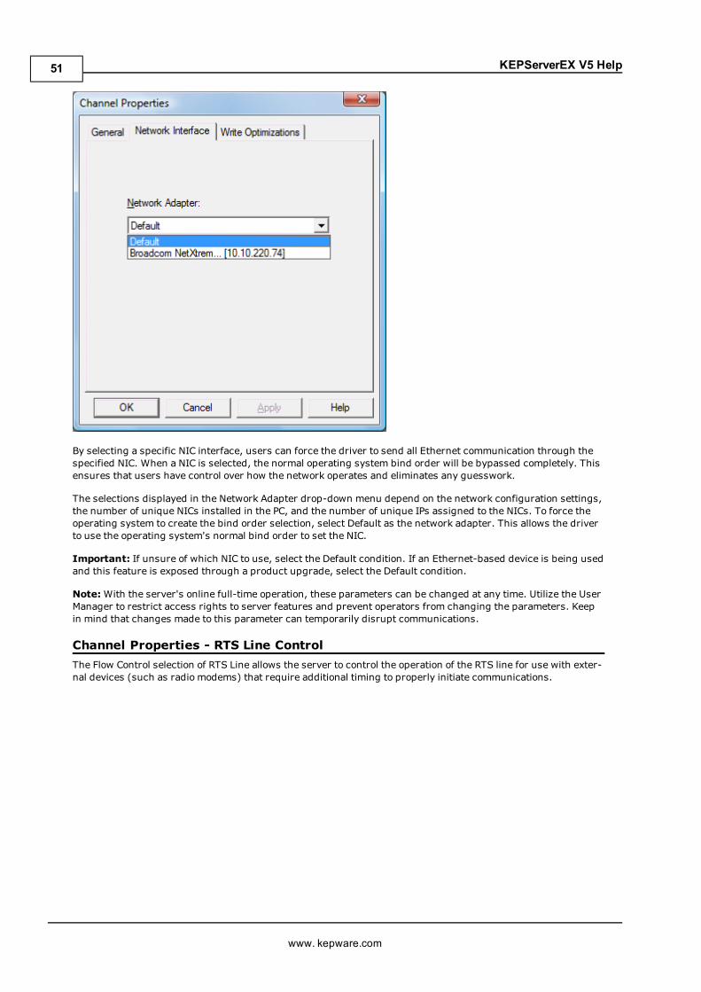
KEPServerEX V5 Help
By selecting a specific NIC interface, users can force the driver to send all Ethernet communication through thespecified NIC. When a NIC is selected, the normal operating system bind order will be bypassed completely. Thisensures that users have control over how the network operates and eliminates any guesswork.
The selections displayed in the Network Adapter drop-down menu depend on the network configuration settings,the number of unique NICs installed in the PC, and the number of unique IPs assigned to the NICs. To force theoperating system to create the bind order selection, select Default as the network adapter. This allows the driverto use the operating system's normal bind order to set the NIC.
Important: If unsure of which NIC to use, select the Default condition. If an Ethernet-based device is being usedand this feature is exposed through a product upgrade, select the Default condition.
Note:With the server's online full-time operation, these parameters can be changed at any time. Utilize the UserManager to restrict access rights to server features and prevent operators from changing the parameters. Keepin mind that changes made to this parameter can temporarily disrupt communications.
Channel Properties - RTS Line ControlThe Flow Control selection of RTS Line allows the server to control the operation of the RTS line for use with exter-nal devices (such as radio modems) that require additional timing to properly initiate communications.
www. kepware.com
51
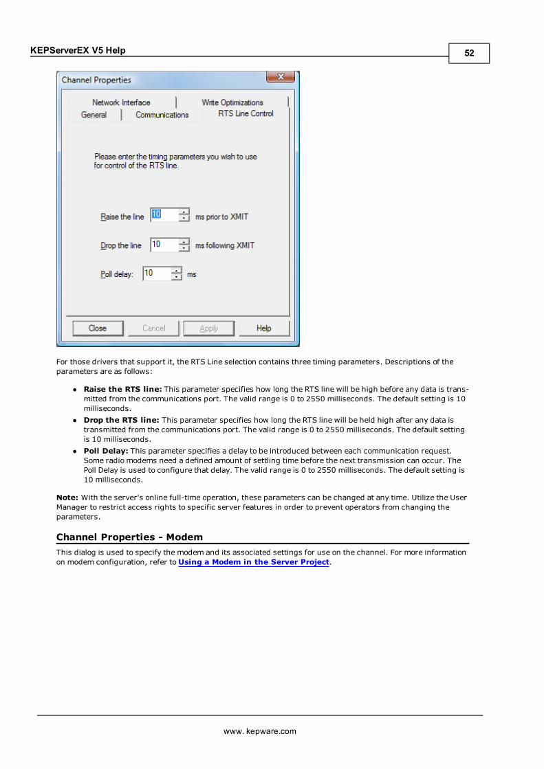
KEPServerEX V5 Help
For those drivers that support it, the RTS Line selection contains three timing parameters. Descriptions of theparameters are as follows:
l Raise the RTS line: This parameter specifies how long the RTS line will be high before any data is trans-mitted from the communications port. The valid range is 0 to 2550 milliseconds. The default setting is 10milliseconds.
l Drop the RTS line: This parameter specifies how long the RTS line will be held high after any data istransmitted from the communications port. The valid range is 0 to 2550 milliseconds. The default settingis 10 milliseconds.
l Poll Delay: This parameter specifies a delay to be introduced between each communication request.Some radio modems need a defined amount of settling time before the next transmission can occur. ThePoll Delay is used to configure that delay. The valid range is 0 to 2550 milliseconds. The default setting is10 milliseconds.
Note: With the server's online full-time operation, these parameters can be changed at any time. Utilize the UserManager to restrict access rights to specific server features in order to prevent operators from changing theparameters.
Channel Properties - ModemThis dialog is used to specify the modem and its associated settings for use on the channel. For more informationon modem configuration, refer toUsing a Modem in the Server Project.
www. kepware.com
52
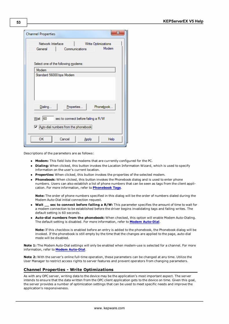
KEPServerEX V5 Help
Descriptions of the parameters are as follows:
l Modem: This field lists the modems that are currently configured for the PC.l Dialing:When clicked, this button invokes the Location Information Wizard, which is used to specifyinformation on the user's current location.
l Properties:When clicked, this button invokes the properties of the selected modem.l Phonebook:When clicked, this button invokes the Phonebook dialog and is used to enter phonenumbers. Users can also establish a list of phone numbers that can be seen as tags from the client appli-cation. For more information, refer to Phonebook Tags.
Note: The order of phone numbers specified in this dialog will be the order of numbers dialed during theModem Auto-Dial initial connection request.
l Wait __ sec to connect before failing a R/W: This parameter specifies the amount of time to wait fora modem connection to be established before the driver begins invalidating tags and failing writes. Thedefault setting is 60 seconds.
l Auto-dial numbers from the phonebook:When checked, this option will enable Modem Auto-Dialing.The default setting is disabled. For more information, refer toModem Auto-Dial.
Note: If this checkbox is enabled before an entry is added to the phonebook, the Phonebook dialog will beinvoked. If the phonebook is still empty by the time that the changes are applied to the page, auto-dialmode will be disabled.
Note 1: The Modem Auto-Dial settings will only be enabled when modem-use is selected for a channel. For moreinformation, refer toModem Auto-Dial.
Note 2:With the server's online full-time operation, these parameters can be changed at any time. Utilize theUser Manager to restrict access rights to server features and prevent operators from changing parameters.
Channel Properties - Write OptimizationsAs with any OPC server, writing data to the device may be the application's most important aspect. The serverintends to ensure that the data written from the OPC client application gets to the device on time. Given this goal,the server provides a number of optimization settings that can be used to meet specific needs and improve theapplication's responsiveness.
www. kepware.com
53
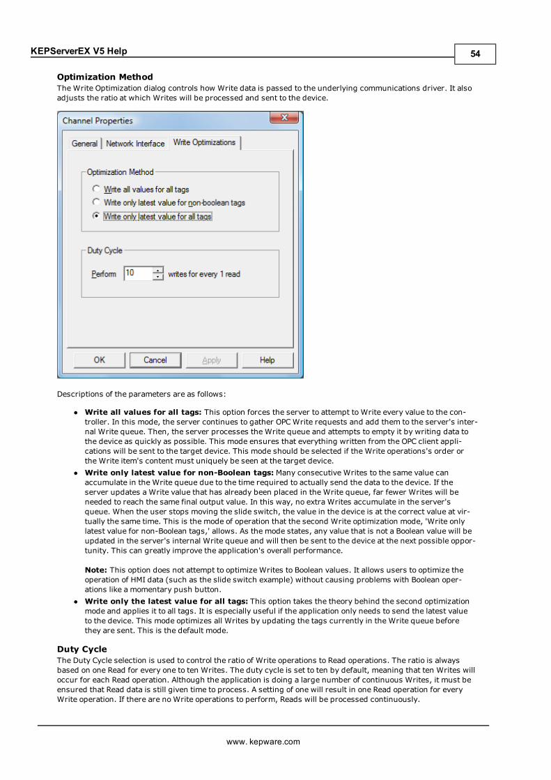
KEPServerEX V5 Help
Optimization MethodThe Write Optimization dialog controls how Write data is passed to the underlying communications driver. It alsoadjusts the ratio at which Writes will be processed and sent to the device.
Descriptions of the parameters are as follows:
l Write all values for all tags: This option forces the server to attempt to Write every value to the con-troller. In this mode, the server continues to gather OPCWrite requests and add them to the server's inter-nal Write queue. Then, the server processes the Write queue and attempts to empty it by writing data tothe device as quickly as possible. This mode ensures that everything written from the OPC client appli-cations will be sent to the target device. This mode should be selected if the Write operations's order orthe Write item's content must uniquely be seen at the target device.
l Write only latest value for non-Boolean tags: Many consecutive Writes to the same value canaccumulate in the Write queue due to the time required to actually send the data to the device. If theserver updates a Write value that has already been placed in the Write queue, far fewer Writes will beneeded to reach the same final output value. In this way, no extra Writes accumulate in the server'squeue. When the user stops moving the slide switch, the value in the device is at the correct value at vir-tually the same time. This is the mode of operation that the second Write optimization mode, 'Write onlylatest value for non-Boolean tags,' allows. As the mode states, any value that is not a Boolean value will beupdated in the server's internal Write queue and will then be sent to the device at the next possible oppor-tunity. This can greatly improve the application's overall performance.
Note: This option does not attempt to optimize Writes to Boolean values. It allows users to optimize theoperation of HMI data (such as the slide switch example) without causing problems with Boolean oper-ations like a momentary push button.
l Write only the latest value for all tags: This option takes the theory behind the second optimizationmode and applies it to all tags. It is especially useful if the application only needs to send the latest valueto the device. This mode optimizes all Writes by updating the tags currently in the Write queue beforethey are sent. This is the default mode.
Duty CycleThe Duty Cycle selection is used to control the ratio of Write operations to Read operations. The ratio is alwaysbased on one Read for every one to ten Writes. The duty cycle is set to ten by default, meaning that ten Writes willoccur for each Read operation. Although the application is doing a large number of continuous Writes, it must beensured that Read data is still given time to process. A setting of one will result in one Read operation for everyWrite operation. If there are noWrite operations to perform, Reads will be processed continuously.
www. kepware.com
54
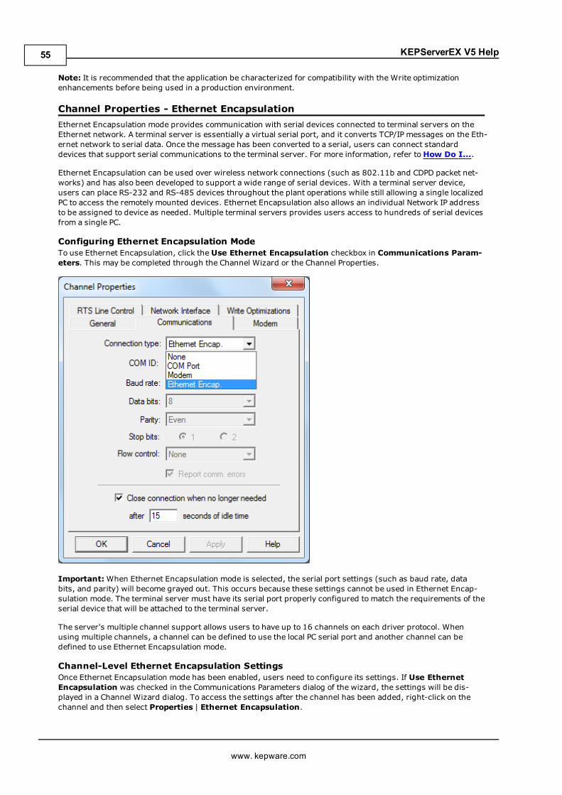
KEPServerEX V5 Help
Note: It is recommended that the application be characterized for compatibility with the Write optimizationenhancements before being used in a production environment.
Channel Properties - Ethernet EncapsulationEthernet Encapsulation mode provides communication with serial devices connected to terminal servers on theEthernet network. A terminal server is essentially a virtual serial port, and it converts TCP/IP messages on the Eth-ernet network to serial data. Once the message has been converted to a serial, users can connect standarddevices that support serial communications to the terminal server. For more information, refer toHow Do I....
Ethernet Encapsulation can be used over wireless network connections (such as 802.11b and CDPD packet net-works) and has also been developed to support a wide range of serial devices. With a terminal server device,users can place RS-232 and RS-485 devices throughout the plant operations while still allowing a single localizedPC to access the remotely mounted devices. Ethernet Encapsulation also allows an individual Network IP addressto be assigned to device as needed. Multiple terminal servers provides users access to hundreds of serial devicesfrom a single PC.
Configuring Ethernet Encapsulation ModeTo use Ethernet Encapsulation, click the Use Ethernet Encapsulation checkbox in Communications Param-eters. This may be completed through the Channel Wizard or the Channel Properties.
Important:When Ethernet Encapsulation mode is selected, the serial port settings (such as baud rate, databits, and parity) will become grayed out. This occurs because these settings cannot be used in Ethernet Encap-sulation mode. The terminal server must have its serial port properly configured to match the requirements of theserial device that will be attached to the terminal server.
The server's multiple channel support allows users to have up to 16 channels on each driver protocol. Whenusing multiple channels, a channel can be defined to use the local PC serial port and another channel can bedefined to use Ethernet Encapsulation mode.
Channel-Level Ethernet Encapsulation SettingsOnce Ethernet Encapsulation mode has been enabled, users need to configure its settings. If Use EthernetEncapsulation was checked in the Communications Parameters dialog of the wizard, the settings will be dis-played in a Channel Wizard dialog. To access the settings after the channel has been added, right-click on thechannel and then select Properties | Ethernet Encapsulation.
www. kepware.com
55
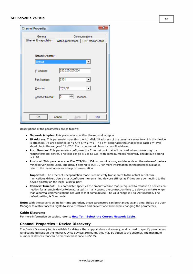
KEPServerEX V5 Help
Descriptions of the parameters are as follows:
l Network Adapter: This parameter specifies the network adapter.l IP Address: This parameter specifies the four-field IP address of the terminal server to which this deviceis attached. IPs are specified as YYY.YYY.YYY.YYY. The YYY designates the IP address: each YYY byteshould be in the range of 0 to 255. Each channel will have its own IP address.
l Port Number: This parameter configures the Ethernet port that will be used when connecting to aremote terminal server. The valid range is 1 to 65535, with some numbers reserved. The default settingis 2101.
l Protocol: This parameter specifies TCP/IP or UDP communications, and depends on the nature of the ter-minal server being used. The default setting is TCP/IP. For more information on the protocol available,refer to the terminal server's help documentation.
Important: The Ethernet Encapsulation mode is completely transparent to the actual serial com-munications driver. Users must configure the remaining device settings as if they were connecting to thedevice directly on the local PC serial port.
l Connect Timeout: This parameter specifies the amount of time that is required to establish a socket con-nection for a remote device to be adjusted. In many cases, the connection time to a device can take longerthan a normal communications request to that same device. The valid range is 1 to 999 seconds. Thedefault setting is 3 seconds.
Note: With the server's online full-time operation, these parameters can be changed at any time. Utilize the UserManager to restrict access rights to server features and prevent operators from changing the parameters.
Cable DiagramsFor more information on cables, refer toHow To... Select the Correct Network Cable.
Channel Properties - Device DiscoveryThe Device Discovery tab is available for drivers that support device discovery, and is used to specify parametersfor locating devices on the network. Once devices are found, they may be added to the channel. The maximumnumber of devices that can be discovered at once is 65535.
www. kepware.com
56
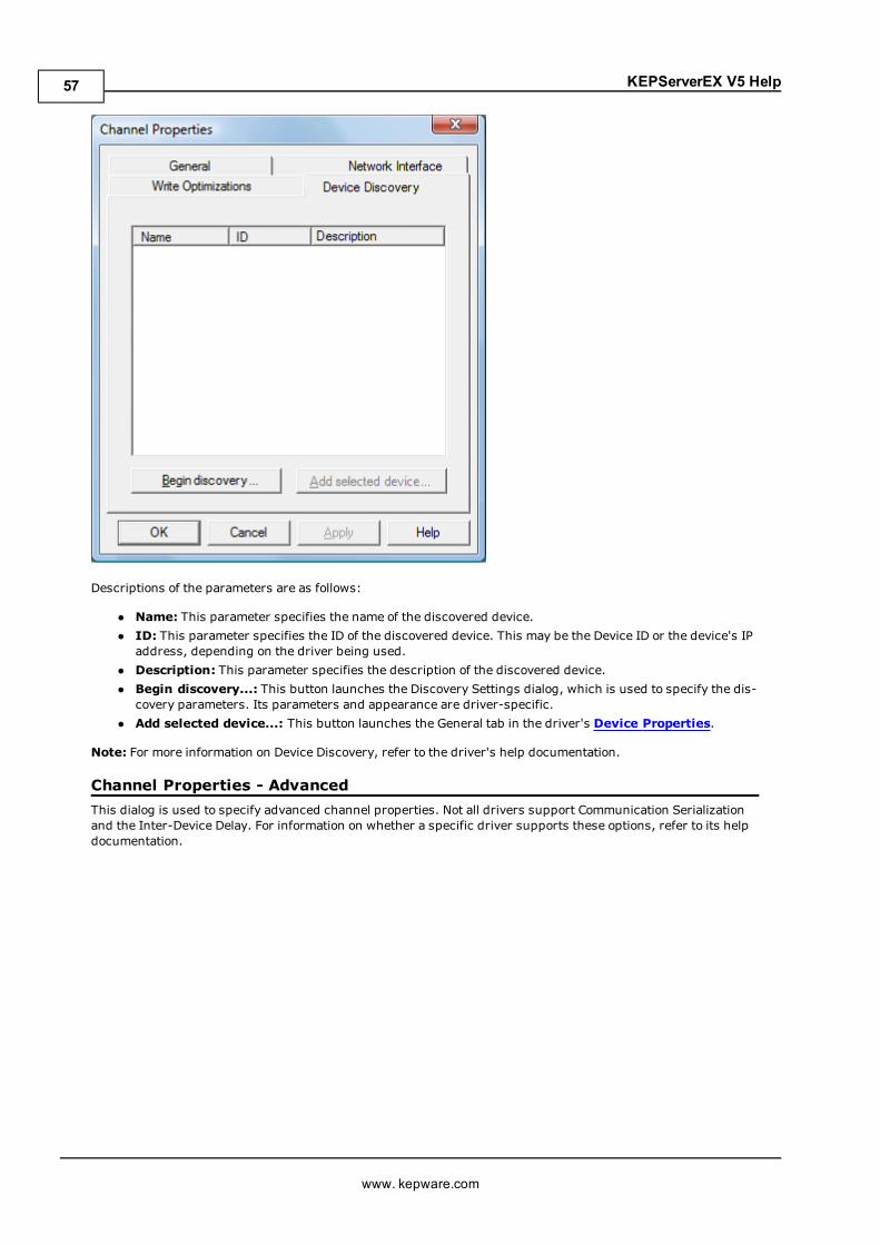
KEPServerEX V5 Help
Descriptions of the parameters are as follows:
l Name: This parameter specifies the name of the discovered device.l ID: This parameter specifies the ID of the discovered device. This may be the Device ID or the device's IPaddress, depending on the driver being used.
l Description: This parameter specifies the description of the discovered device.l Begin discovery...: This button launches the Discovery Settings dialog, which is used to specify the dis-covery parameters. Its parameters and appearance are driver-specific.
l Add selected device...: This button launches the General tab in the driver's Device Properties.
Note: For more information on Device Discovery, refer to the driver's help documentation.
Channel Properties - AdvancedThis dialog is used to specify advanced channel properties. Not all drivers support Communication Serializationand the Inter-Device Delay. For information on whether a specific driver supports these options, refer to its helpdocumentation.
www. kepware.com
57
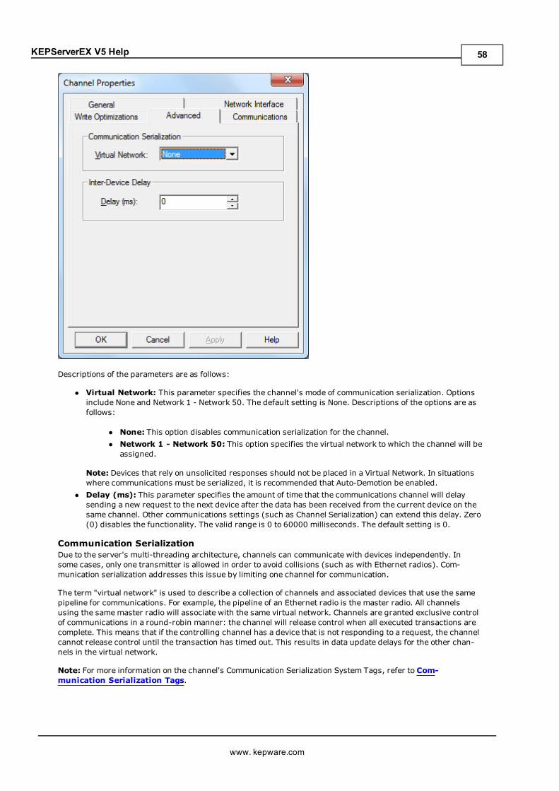
KEPServerEX V5 Help
Descriptions of the parameters are as follows:
l Virtual Network: This parameter specifies the channel's mode of communication serialization. Optionsinclude None and Network 1 - Network 50. The default setting is None. Descriptions of the options are asfollows:
l None: This option disables communication serialization for the channel.l Network 1 - Network 50: This option specifies the virtual network to which the channel will beassigned.
Note: Devices that rely on unsolicited responses should not be placed in a Virtual Network. In situationswhere communications must be serialized, it is recommended that Auto-Demotion be enabled.
l Delay (ms): This parameter specifies the amount of time that the communications channel will delaysending a new request to the next device after the data has been received from the current device on thesame channel. Other communications settings (such as Channel Serialization) can extend this delay. Zero(0) disables the functionality. The valid range is 0 to 60000 milliseconds. The default setting is 0.
Communication SerializationDue to the server's multi-threading architecture, channels can communicate with devices independently. Insome cases, only one transmitter is allowed in order to avoid collisions (such as with Ethernet radios). Com-munication serialization addresses this issue by limiting one channel for communication.
The term "virtual network" is used to describe a collection of channels and associated devices that use the samepipeline for communications. For example, the pipeline of an Ethernet radio is the master radio. All channelsusing the samemaster radio will associate with the same virtual network. Channels are granted exclusive controlof communications in a round-robin manner: the channel will release control when all executed transactions arecomplete. This means that if the controlling channel has a device that is not responding to a request, the channelcannot release control until the transaction has timed out. This results in data update delays for the other chan-nels in the virtual network.
Note: For more information on the channel's Communication Serialization System Tags, refer to Com-munication Serialization Tags.
www. kepware.com
58
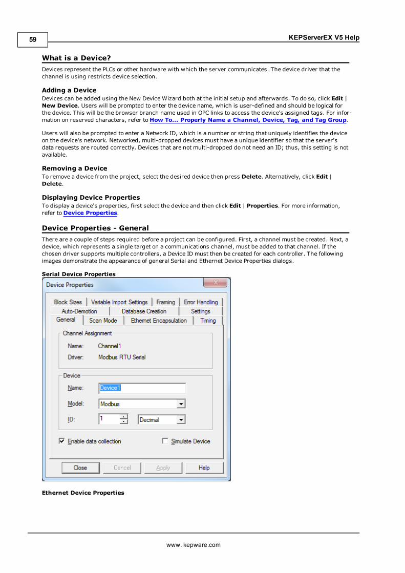
KEPServerEX V5 Help
What is a Device?Devices represent the PLCs or other hardware with which the server communicates. The device driver that thechannel is using restricts device selection.
Adding a DeviceDevices can be added using the New Device Wizard both at the initial setup and afterwards. To do so, click Edit |New Device. Users will be prompted to enter the device name, which is user-defined and should be logical forthe device. This will be the browser branch name used in OPC links to access the device's assigned tags. For infor-mation on reserved characters, refer toHow To... Properly Name a Channel, Device, Tag, and Tag Group.
Users will also be prompted to enter a Network ID, which is a number or string that uniquely identifies the deviceon the device's network. Networked, multi-dropped devices must have a unique identifier so that the server'sdata requests are routed correctly. Devices that are not multi-dropped do not need an ID; thus, this setting is notavailable.
Removing a DeviceTo remove a device from the project, select the desired device then press Delete. Alternatively, click Edit |Delete.
Displaying Device PropertiesTo display a device's properties, first select the device and then click Edit | Properties. For more information,refer toDevice Properties.
Device Properties - GeneralThere are a couple of steps required before a project can be configured. First, a channel must be created. Next, adevice, which represents a single target on a communications channel, must be added to that channel. If thechosen driver supports multiple controllers, a Device ID must then be created for each controller. The followingimages demonstrate the appearance of general Serial and Ethernet Device Properties dialogs.
Serial Device Properties
Ethernet Device Properties
www. kepware.com
59
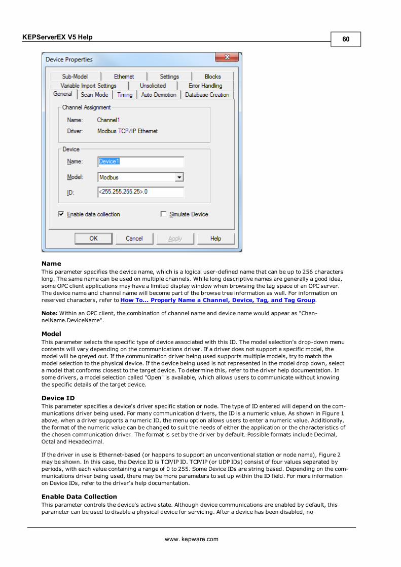
KEPServerEX V5 Help
NameThis parameter specifies the device name, which is a logical user-defined name that can be up to 256 characterslong. The same name can be used on multiple channels. While long descriptive names are generally a good idea,some OPC client applications may have a limited display window when browsing the tag space of an OPC server.The device name and channel name will become part of the browse tree information as well. For information onreserved characters, refer toHow To... Properly Name a Channel, Device, Tag, and Tag Group.
Note:Within an OPC client, the combination of channel name and device name would appear as "Chan-nelName.DeviceName".
ModelThis parameter selects the specific type of device associated with this ID. The model selection's drop-down menucontents will vary depending on the communications driver. If a driver does not support a specific model, themodel will be greyed out. If the communication driver being used supports multiple models, try to match themodel selection to the physical device. If the device being used is not represented in the model drop down, selecta model that conforms closest to the target device. To determine this, refer to the driver help documentation. Insome drivers, a model selection called "Open" is available, which allows users to communicate without knowingthe specific details of the target device.
Device IDThis parameter specifies a device's driver specific station or node. The type of ID entered will depend on the com-munications driver being used. For many communication drivers, the ID is a numeric value. As shown in Figure 1above, when a driver supports a numeric ID, the menu option allows users to enter a numeric value. Additionally,the format of the numeric value can be changed to suit the needs of either the application or the characteristics ofthe chosen communication driver. The format is set by the driver by default. Possible formats include Decimal,Octal and Hexadecimal.
If the driver in use is Ethernet-based (or happens to support an unconventional station or node name), Figure 2may be shown. In this case, the Device ID is TCP/IP ID. TCP/IP (or UDP IDs) consist of four values separated byperiods, with each value containing a range of 0 to 255. Some Device IDs are string based. Depending on the com-munications driver being used, there may be more parameters to set up within the ID field. For more informationon Device IDs, refer to the driver's help documentation.
Enable Data CollectionThis parameter controls the device's active state. Although device communications are enabled by default, thisparameter can be used to disable a physical device for servicing. After a device has been disabled, no
www. kepware.com
60
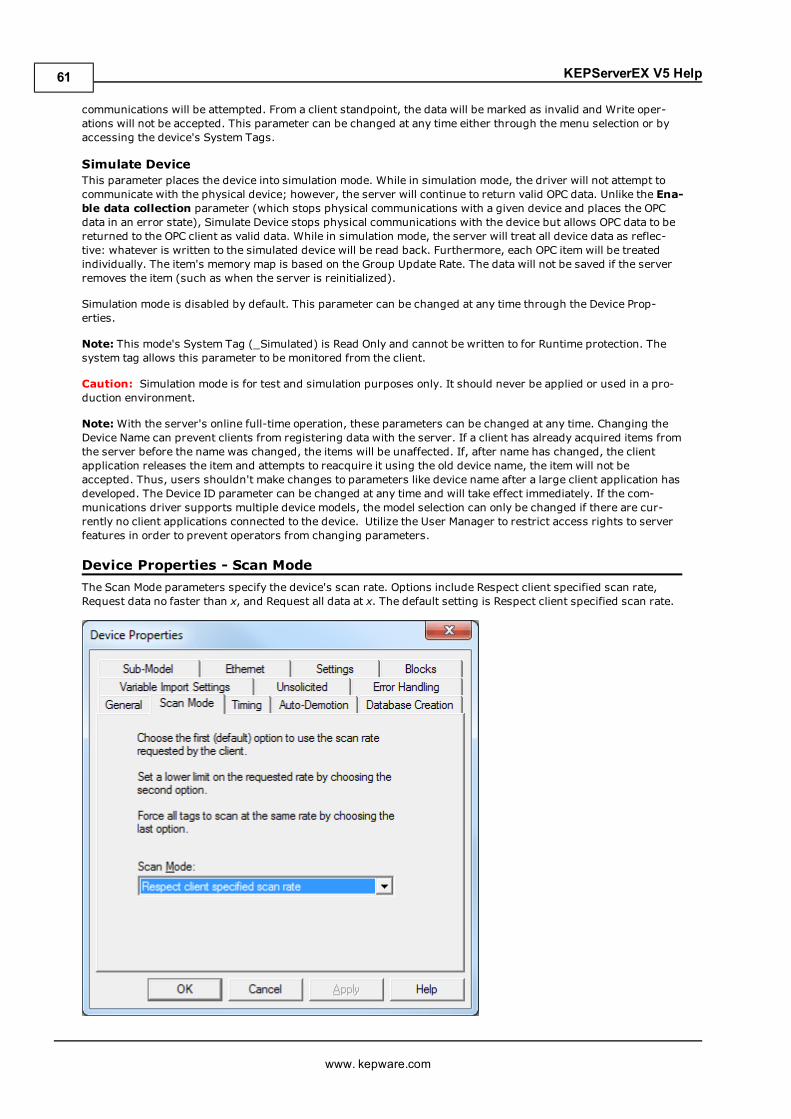
KEPServerEX V5 Help
communications will be attempted. From a client standpoint, the data will be marked as invalid and Write oper-ations will not be accepted. This parameter can be changed at any time either through the menu selection or byaccessing the device's System Tags.
Simulate DeviceThis parameter places the device into simulation mode. While in simulation mode, the driver will not attempt tocommunicate with the physical device; however, the server will continue to return valid OPC data. Unlike the Ena-ble data collection parameter (which stops physical communications with a given device and places the OPCdata in an error state), Simulate Device stops physical communications with the device but allows OPC data to bereturned to the OPC client as valid data. While in simulation mode, the server will treat all device data as reflec-tive: whatever is written to the simulated device will be read back. Furthermore, each OPC item will be treatedindividually. The item's memory map is based on the Group Update Rate. The data will not be saved if the serverremoves the item (such as when the server is reinitialized).
Simulation mode is disabled by default. This parameter can be changed at any time through the Device Prop-erties.
Note: This mode's System Tag (_Simulated) is Read Only and cannot be written to for Runtime protection. Thesystem tag allows this parameter to be monitored from the client.
Caution: Simulation mode is for test and simulation purposes only. It should never be applied or used in a pro-duction environment.
Note:With the server's online full-time operation, these parameters can be changed at any time. Changing theDevice Name can prevent clients from registering data with the server. If a client has already acquired items fromthe server before the name was changed, the items will be unaffected. If, after name has changed, the clientapplication releases the item and attempts to reacquire it using the old device name, the item will not beaccepted. Thus, users shouldn't make changes to parameters like device name after a large client application hasdeveloped. The Device ID parameter can be changed at any time and will take effect immediately. If the com-munications driver supports multiple device models, the model selection can only be changed if there are cur-rently no client applications connected to the device. Utilize the User Manager to restrict access rights to serverfeatures in order to prevent operators from changing parameters.
Device Properties - Scan ModeThe Scan Mode parameters specify the device's scan rate. Options include Respect client specified scan rate,Request data no faster than x, and Request all data at x. The default setting is Respect client specified scan rate.
www. kepware.com
61
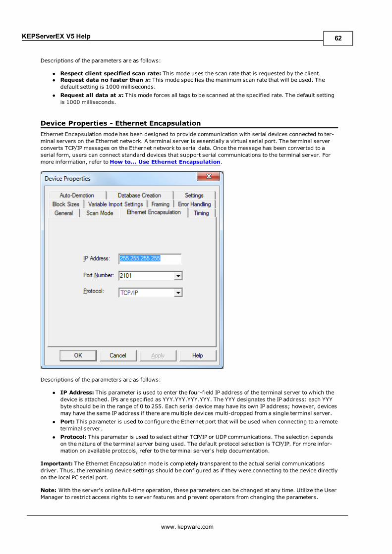
KEPServerEX V5 Help
Descriptions of the parameters are as follows:
l Respect client specified scan rate: This mode uses the scan rate that is requested by the client.l Request data no faster than x: This mode specifies the maximum scan rate that will be used. Thedefault setting is 1000 milliseconds.
l Request all data at x: This mode forces all tags to be scanned at the specified rate. The default settingis 1000 milliseconds.
Device Properties - Ethernet EncapsulationEthernet Encapsulation mode has been designed to provide communication with serial devices connected to ter-minal servers on the Ethernet network. A terminal server is essentially a virtual serial port. The terminal serverconverts TCP/IP messages on the Ethernet network to serial data. Once the message has been converted to aserial form, users can connect standard devices that support serial communications to the terminal server. Formore information, refer toHow to... Use Ethernet Encapsulation.
Descriptions of the parameters are as follows:
l IP Address: This parameter is used to enter the four-field IP address of the terminal server to which thedevice is attached. IPs are specified as YYY.YYY.YYY.YYY. The YYY designates the IP address: each YYYbyte should be in the range of 0 to 255. Each serial device may have its own IP address; however, devicesmay have the same IP address if there are multiple devices multi-dropped from a single terminal server.
l Port: This parameter is used to configure the Ethernet port that will be used when connecting to a remoteterminal server.
l Protocol: This parameter is used to select either TCP/IP or UDP communications. The selection dependson the nature of the terminal server being used. The default protocol selection is TCP/IP. For more infor-mation on available protocols, refer to the terminal server's help documentation.
Important: The Ethernet Encapsulation mode is completely transparent to the actual serial communicationsdriver. Thus, the remaining device settings should be configured as if they were connecting to the device directlyon the local PC serial port.
Note: With the server's online full-time operation, these parameters can be changed at any time. Utilize the UserManager to restrict access rights to server features and prevent operators from changing the parameters.
www. kepware.com
62
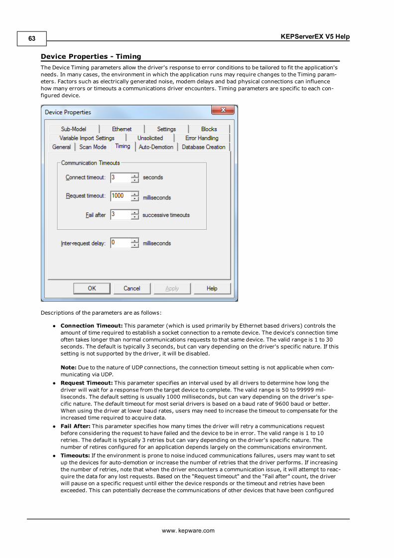
KEPServerEX V5 Help
Device Properties - TimingThe Device Timing parameters allow the driver's response to error conditions to be tailored to fit the application'sneeds. In many cases, the environment in which the application runs may require changes to the Timing param-eters. Factors such as electrically generated noise, modem delays and bad physical connections can influencehow many errors or timeouts a communications driver encounters. Timing parameters are specific to each con-figured device.
Descriptions of the parameters are as follows:
l Connection Timeout: This parameter (which is used primarily by Ethernet based drivers) controls theamount of time required to establish a socket connection to a remote device. The device's connection timeoften takes longer than normal communications requests to that same device. The valid range is 1 to 30seconds. The default is typically 3 seconds, but can vary depending on the driver's specific nature. If thissetting is not supported by the driver, it will be disabled.
Note: Due to the nature of UDP connections, the connection timeout setting is not applicable when com-municating via UDP.
l Request Timeout: This parameter specifies an interval used by all drivers to determine how long thedriver will wait for a response from the target device to complete. The valid range is 50 to 99999 mil-liseconds. The default setting is usually 1000 milliseconds, but can vary depending on the driver's spe-cific nature. The default timeout for most serial drivers is based on a baud rate of 9600 baud or better.When using the driver at lower baud rates, users may need to increase the timeout to compensate for theincreased time required to acquire data.
l Fail After: This parameter specifies how many times the driver will retry a communications requestbefore considering the request to have failed and the device to be in error. The valid range is 1 to 10retries. The default is typically 3 retries but can vary depending on the driver's specific nature. Thenumber of retires configured for an application depends largely on the communications environment.
l Timeouts: If the environment is prone to noise induced communications failures, users may want to setup the devices for auto-demotion or increase the number of retries that the driver performs. If increasingthe number of retries, note that when the driver encounters a communication issue, it will attempt to reac-quire the data for any lost requests. Based on the "Request timeout" and the "Fail after" count, the driverwill pause on a specific request until either the device responds or the timeout and retries have beenexceeded. This can potentially decrease the communications of other devices that have been configured
www. kepware.com
63
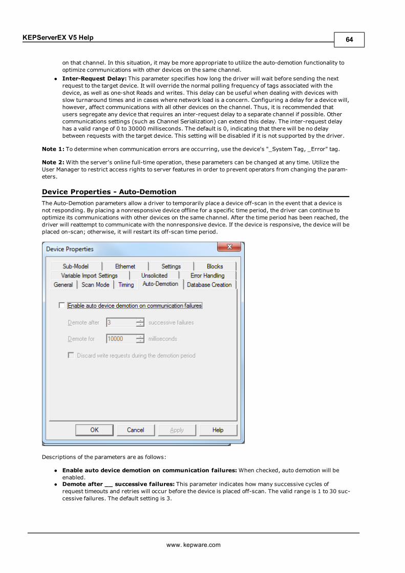
KEPServerEX V5 Help
on that channel. In this situation, it may be more appropriate to utilize the auto-demotion functionality tooptimize communications with other devices on the same channel.
l Inter-Request Delay: This parameter specifies how long the driver will wait before sending the nextrequest to the target device. It will override the normal polling frequency of tags associated with thedevice, as well as one-shot Reads and writes. This delay can be useful when dealing with devices withslow turnaround times and in cases where network load is a concern. Configuring a delay for a device will,however, affect communications with all other devices on the channel. Thus, it is recommended thatusers segregate any device that requires an inter-request delay to a separate channel if possible. Othercommunications settings (such as Channel Serialization) can extend this delay. The inter-request delayhas a valid range of 0 to 30000 milliseconds. The default is 0, indicating that there will be no delaybetween requests with the target device. This setting will be disabled if it is not supported by the driver.
Note 1: To determine when communication errors are occurring, use the device's "_System Tag, _Error" tag.
Note 2:With the server's online full-time operation, these parameters can be changed at any time. Utilize theUser Manager to restrict access rights to server features in order to prevent operators from changing the param-eters.
Device Properties - Auto-DemotionThe Auto-Demotion parameters allow a driver to temporarily place a device off-scan in the event that a device isnot responding. By placing a nonresponsive device offline for a specific time period, the driver can continue tooptimize its communications with other devices on the same channel. After the time period has been reached, thedriver will reattempt to communicate with the nonresponsive device. If the device is responsive, the device will beplaced on-scan; otherwise, it will restart its off-scan time period.
Descriptions of the parameters are as follows:
l Enable auto device demotion on communication failures:When checked, auto demotion will beenabled.
l Demote after __ successive failures: This parameter indicates how many successive cycles ofrequest timeouts and retries will occur before the device is placed off-scan. The valid range is 1 to 30 suc-cessive failures. The default setting is 3.
www. kepware.com
64
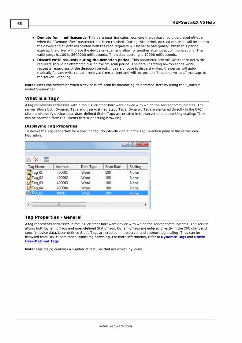
KEPServerEX V5 Help
l Demote for __milliseconds: This parameter indicates how long the device should be placed off-scanwhen the "Demote after" parameter has been reached. During this period, no read requests will be sent tothe device and all data associated with the read requests will be set to bad quality. When this periodexpires, the driver will place the device on-scan and allow for another attempt at communications. Thevalid range is 100 to 3600000 milliseconds. The default setting is 10000 milliseconds.
l Discard write requests during the demotion period: This parameter controls whether or not Writerequests should be attempted during the off-scan period. The default setting always sends writerequests regardless of the demotion period. If users choose to discard writes, the server will auto-matically fail any write request received from a client and will not post an "Unable to write..." message tothe server Event Log.
Note: Users can determine when a device is off-scan by monitoring its demoted state by using the "_AutoDe-moted System" tag.
What is a Tag?A tag represents addresses within the PLC or other hardware device with which the server communicates. Theserver allows both Dynamic Tags and user-defined Static Tags. Dynamic Tags are entered directly in the OPCclient and specify device data. User-defined Static Tags are created in the server and support tag scaling. Theycan be browsed from OPC clients that support tag browsing.
Displaying Tag PropertiesTo invoke the Tag Properties for a specific tag, double-click on it in the Tag Selection pane of the server con-figuration.
Tag Properties - GeneralA tag represents addresses in the PLC or other hardware device with which the server communicates. The serverallows both Dynamic Tags and user-defined Static Tags. Dynamic Tags are entered directly in the OPC client andspecify device data. User-defined Static Tags are created in the server and support tag scaling. They can bebrowsed from OPC clients that support tag browsing. For more information, refer toDynamic Tags and StaticUser-Defined Tags.
Note: This dialog contains a number of features that are driven by icons.
www. kepware.com
65
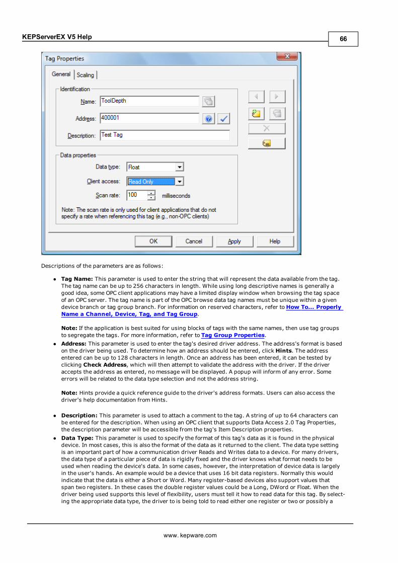
KEPServerEX V5 Help
Descriptions of the parameters are as follows:
l Tag Name: This parameter is used to enter the string that will represent the data available from the tag.The tag name can be up to 256 characters in length. While using long descriptive names is generally agood idea, some OPC client applications may have a limited display window when browsing the tag spaceof an OPC server. The tag name is part of the OPC browse data tag names must be unique within a givendevice branch or tag group branch. For information on reserved characters, refer toHow To... ProperlyName a Channel, Device, Tag, and Tag Group.
Note: If the application is best suited for using blocks of tags with the same names, then use tag groupsto segregate the tags. For more information, refer to Tag Group Properties.
l Address: This parameter is used to enter the tag's desired driver address. The address's format is basedon the driver being used. To determine how an address should be entered, click Hints. The addressentered can be up to 128 characters in length. Once an address has been entered, it can be tested byclicking Check Address, which will then attempt to validate the address with the driver. If the driveraccepts the address as entered, no message will be displayed. A popup will inform of any error. Someerrors will be related to the data type selection and not the address string.
Note: Hints provide a quick reference guide to the driver's address formats. Users can also access thedriver's help documentation from Hints.
l Description: This parameter is used to attach a comment to the tag. A string of up to 64 characters canbe entered for the description. When using an OPC client that supports Data Access 2.0 Tag Properties,the description parameter will be accessible from the tag's Item Description properties.
l Data Type: This parameter is used to specify the format of this tag's data as it is found in the physicaldevice. In most cases, this is also the format of the data as it returned to the client. The data type settingis an important part of how a communication driver Reads and Writes data to a device. For many drivers,the data type of a particular piece of data is rigidly fixed and the driver knows what format needs to beused when reading the device's data. In some cases, however, the interpretation of device data is largelyin the user's hands. An example would be a device that uses 16 bit data registers. Normally this wouldindicate that the data is either a Short or Word. Many register-based devices also support values thatspan two registers. In these cases the double register values could be a Long, DWord or Float. When thedriver being used supports this level of flexibility, users must tell it how to read data for this tag. By select-ing the appropriate data type, the driver to is being told to read either one register or two or possibly a
www. kepware.com
66
KEPServerEX V5 Help
Boolean value. The driver governs the data format being choosen. For specific information on availabledata types, click Hints to access the driver's help documentation. Available data type selections are as fol-lows:
Default - This selection allows the driver to choose its default data type. Boolean - Single bit data On or Off. Char - Signed 8 bit data. Byte - Unsigned 8 bit data. Short - Signed 16 bit data. Word - Unsigned 16 bit data. Long - Signed 32 bit data. DWord - Unsigned 32 bit data. Float - 32 bit Real value IEEE format. Double - 64 bit Real value IEEE format. String - Null terminated ASCII string. BCD - Two byte-packed BCD value range is 0-9999. LBCD - Four byte-packed BCD value range is 0-99999999. Date - 64 bit Real value representing the number of days since December 31, 1899.
l Client Access: This parameter is used to specify whether the tag is Read Only or Read/Write. Byselecting Read Only, users can prevent client applications from changing the data contained in this tag.By selecting Read/Write, users allow client applications to change this tag's value as needed. The Clientaccess selection also affects how the tag appears in the browse space of an OPC client. Many OPC clientapplications allow users to filter tags based on their attributes. Changing the access method of this tagmay change how and when the tag will appear in the browse space of the OPC client.
l Scan Rate: This parameter is used to specify the update interval for this tag when used with a non-OPCclient. OPC clients can control the rate at which data is scanned by using the update rate that is part of allOPC groups. Normally non-OPC clients don't have that luxury. The server is used to specify an update rateon a tag per tag basis for non-OPC clients. Using the scan rate, users can tailor the bandwidth require-ments of the server to suit the needs of the application. If, for example, data that changes very slowlyneeds to be read, there is no reason to read the value very often. Using the scan rate this tag can beforced to read at a slower rate reducing the demand on the communications channel. The valid range is10 to 99999990 ms., with a 10 ms. increment. The default is 100 milliseconds.
Note:With the server's online full-time operation, these parameters can be changed at any time. Changes madeto Tag Properties will take effect immediately; however, OPC clients that have already connected to this tag willnot be affected until they release and attempt to reacquire it. Utilize the User Manager to restrict access rights toserver features and prevent operators from changing the parameters.
Multiple Tag GenerationThe Multiple Tag Generation Tool dynamically creates multiple tags using user-defined driver nomenclature. Itallows a variety of address formats (such as ranges utilizing decimal, hexadecimal, and octal number systems).To avoid overlapping data, the Tag Generator Tool also has the ability to increment by the user-defined data type.
For information on a specific dialog, select a link from the list below:
Add Numeric RangeAdd Static TextAdd Text SequenceMultiple Tag Generation PreviewTag Name Properties
Multiple Tag Generation
www. kepware.com
67
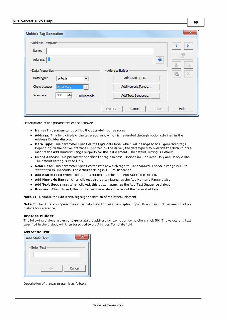
KEPServerEX V5 Help
Descriptions of the parameters are as follows:
l Name: This parameter specifies the user-defined tag name.l Address: This field displays the tag's address, which is generated through options defined in theAddress Builder dialogs.
l Data Type: This parameter specifies the tag's data type, which will be applied to all generated tags.Depending on the native interface supported by the driver, the data type may override the default incre-ment of the Add Numeric Range property for the last element. The default setting is Default.
l Client Access: This parameter specifies the tag's access. Options include Read Only and Read/Write.The default setting is Read Only.
l Scan Rate: This parameter specifies the rate at which tags will be scanned. The valid range is 10 to99999990 milliseconds. The default setting is 100 milliseconds.
l Add Static Text:When clicked, this button launches the Add Static Text dialog.l Add Numeric Range:When clicked, this button launches the Add Numeric Range dialog.l Add Text Sequence:When clicked, this button launches the Add Text Sequence dialog.l Preview:When clicked, this button will generate a preview of the generated tags.
Note 1: To enable the Edit icons, highlight a section of the syntax element.
Note 2: The Hints icon opens the driver help file's Address Description topic. Users can click between the twodialogs for reference.
Address BuilderThe following dialogs are used to generate the address syntax. Upon completion, clickOK. The values and textspecified in the dialogs will then be added to the Address Template field.
Add Static Text
Description of the parameter is as follows:
www. kepware.com
68
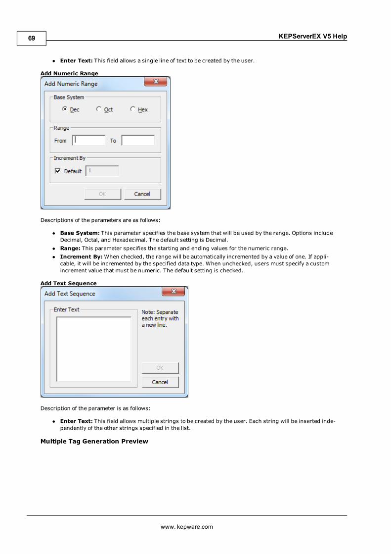
KEPServerEX V5 Help
l Enter Text: This field allows a single line of text to be created by the user.
Add Numeric Range
Descriptions of the parameters are as follows:
l Base System: This parameter specifies the base system that will be used by the range. Options includeDecimal, Octal, and Hexadecimal. The default setting is Decimal.
l Range: This parameter specifies the starting and ending values for the numeric range.l Increment By:When checked, the range will be automatically incremented by a value of one. If appli-cable, it will be incremented by the specified data type. When unchecked, users must specify a customincrement value that must be numeric. The default setting is checked.
Add Text Sequence
Description of the parameter is as follows:
l Enter Text: This field allows multiple strings to be created by the user. Each string will be inserted inde-pendently of the other strings specified in the list.
Multiple Tag Generation Preview
www. kepware.com
69
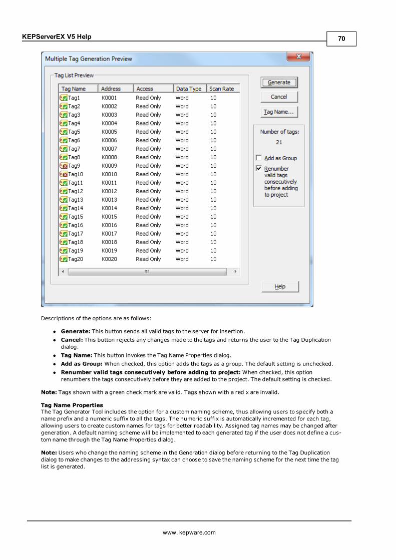
KEPServerEX V5 Help
Descriptions of the options are as follows:
l Generate: This button sends all valid tags to the server for insertion.l Cancel: This button rejects any changes made to the tags and returns the user to the Tag Duplicationdialog.
l Tag Name: This button invokes the Tag Name Properties dialog.l Add as Group: When checked, this option adds the tags as a group. The default setting is unchecked.l Renumber valid tags consecutively before adding to project:When checked, this optionrenumbers the tags consecutively before they are added to the project. The default setting is checked.
Note: Tags shown with a green check mark are valid. Tags shown with a red x are invalid.
Tag Name PropertiesThe Tag Generator Tool includes the option for a custom naming scheme, thus allowing users to specify both aname prefix and a numeric suffix to all the tags. The numeric suffix is automatically incremented for each tag,allowing users to create custom names for tags for better readability. Assigned tag names may be changed aftergeneration. A default naming scheme will be implemented to each generated tag if the user does not define a cus-tom name through the Tag Name Properties dialog.
Note: Users who change the naming scheme in the Generation dialog before returning to the Tag Duplicationdialog to make changes to the addressing syntax can choose to save the naming scheme for the next time the taglist is generated.
www. kepware.com
70
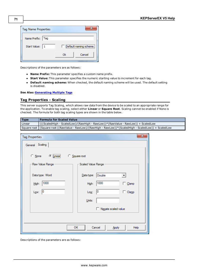
KEPServerEX V5 Help
Descriptions of the parameters are as follows:
l Name Prefix: This parameter specifies a custom name prefix.l Start Value: This parameter specifies the numeric starting value to increment for each tag.l Default naming scheme:When checked, the default naming scheme will be used. The default settingis disabled.
See Also: Generating Multiple Tags
Tag Properties - ScalingThis server supports Tag Scaling, which allows raw data from the device to be scaled to an appropriate range forthe application. To enable tag scaling, select either Linear or Square Root. Scaling cannot be enabled if None ischecked. The formula for both tag scaling types are shown in the table below.
Type Formula for Scaled ValueLinear (((ScaledHigh - ScaledLow)/(RawHigh - RawLow))*(RawValue - RawLow)) + ScaledLowSquare root (Square root ((RawValue - RawLow)/(RawHigh - RawLow))*(ScaledHigh - ScaledLow)) + ScaledLow
Descriptions of the parameters are as follows:
www. kepware.com
71
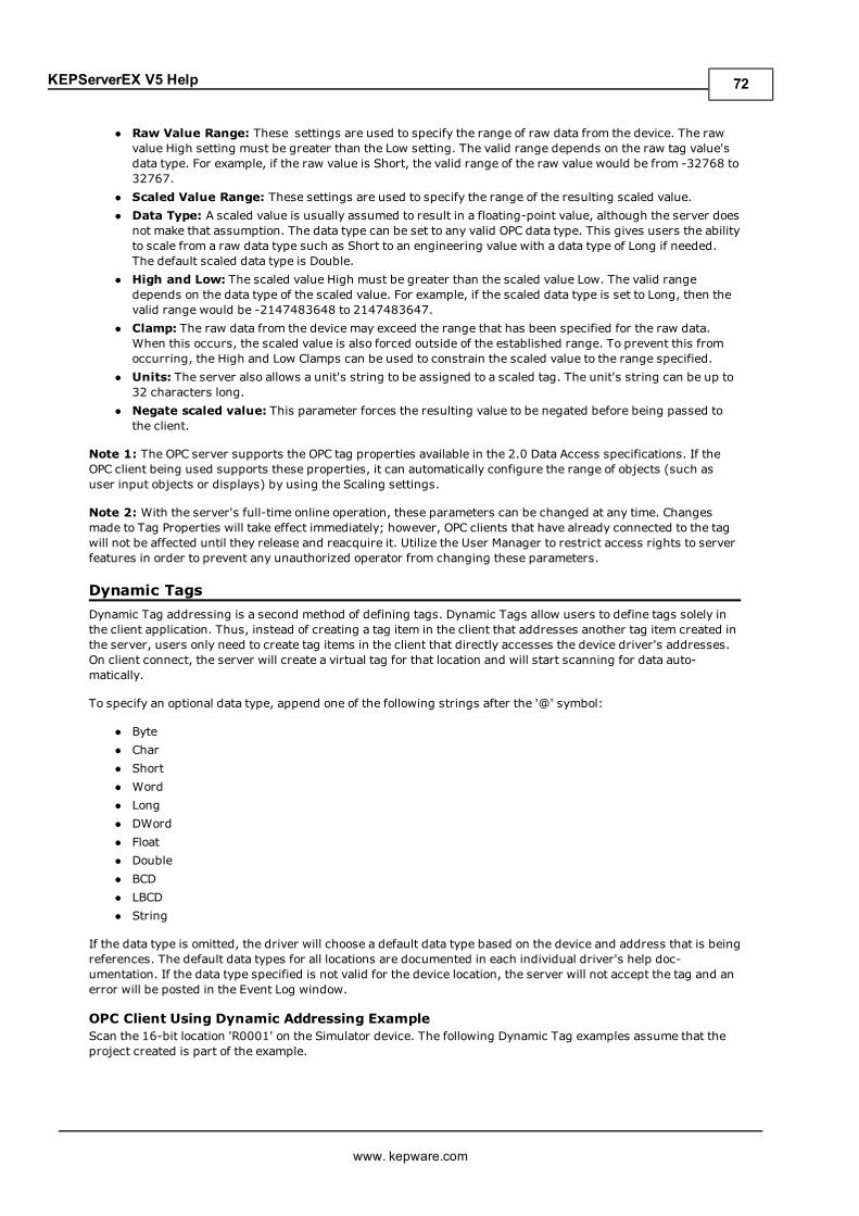
KEPServerEX V5 Help
l Raw Value Range: These settings are used to specify the range of raw data from the device. The rawvalue High setting must be greater than the Low setting. The valid range depends on the raw tag value'sdata type. For example, if the raw value is Short, the valid range of the raw value would be from -32768 to32767.
l Scaled Value Range: These settings are used to specify the range of the resulting scaled value.l Data Type: A scaled value is usually assumed to result in a floating-point value, although the server doesnot make that assumption. The data type can be set to any valid OPC data type. This gives users the abilityto scale from a raw data type such as Short to an engineering value with a data type of Long if needed.The default scaled data type is Double.
l High and Low: The scaled value High must be greater than the scaled value Low. The valid rangedepends on the data type of the scaled value. For example, if the scaled data type is set to Long, then thevalid range would be -2147483648 to 2147483647.
l Clamp: The raw data from the device may exceed the range that has been specified for the raw data.When this occurs, the scaled value is also forced outside of the established range. To prevent this fromoccurring, the High and Low Clamps can be used to constrain the scaled value to the range specified.
l Units: The server also allows a unit's string to be assigned to a scaled tag. The unit's string can be up to32 characters long.
l Negate scaled value: This parameter forces the resulting value to be negated before being passed tothe client.
Note 1: The OPC server supports the OPC tag properties available in the 2.0 Data Access specifications. If theOPC client being used supports these properties, it can automatically configure the range of objects (such asuser input objects or displays) by using the Scaling settings.
Note 2: With the server's full-time online operation, these parameters can be changed at any time. Changesmade to Tag Properties will take effect immediately; however, OPC clients that have already connected to the tagwill not be affected until they release and reacquire it. Utilize the User Manager to restrict access rights to serverfeatures in order to prevent any unauthorized operator from changing these parameters.
Dynamic TagsDynamic Tag addressing is a second method of defining tags. Dynamic Tags allow users to define tags solely inthe client application. Thus, instead of creating a tag item in the client that addresses another tag item created inthe server, users only need to create tag items in the client that directly accesses the device driver's addresses.On client connect, the server will create a virtual tag for that location and will start scanning for data auto-matically.
To specify an optional data type, append one of the following strings after the '@' symbol:
l Bytel Charl Shortl Wordl Longl DWordl Floatl Doublel BCDl LBCDl String
If the data type is omitted, the driver will choose a default data type based on the device and address that is beingreferences. The default data types for all locations are documented in each individual driver's help doc-umentation. If the data type specified is not valid for the device location, the server will not accept the tag and anerror will be posted in the Event Log window.
OPC Client Using Dynamic Addressing ExampleScan the 16-bit location 'R0001' on the Simulator device. The following Dynamic Tag examples assume that theproject created is part of the example.
www. kepware.com
72
KEPServerEX V5 Help
1. Start the OPC client application and connect to the server.
2. Using the Simulator driver, create a channel and name it "Channel1." Then, make a device and name it"Device1."
3. In the client application, define an item name as "Channel1.Device1.R0001@Short."
4. The client project will automatically start receiving data. The default data type for address R0001 in theSimulator device is Word. To override this, the @Short has been appended to select a data type of Short.
Note: When utilizing Dynamic Tags in an OPC client application, the use of the @[Data Type] modifier is not nor-mally required. OPC clients can specify the desired data type as part of the request when registering a link for aspecific data item. The data type specified by the OPC client will be used if it is supported by the communicationsdriver. The @[Data Type] modifier can be useful when ensuring that a communications driver interprets a pieceof data exactly as needed.
Non-OPC Client ExampleNon-OPC clients can override the update rate on a per-tag basis by appending @[Update Rate].
For example, appending "<DDE service name>|_ddedata!Device1.R0001@500" will override just the updaterate. " <DDE service name>|_ddedata!Device1.R0001@500,Short" will override both update rate and data type.
See Also: Static Tags (User-Defined) and Designing a Project: Adding User-Defined Tags.
Note 1: For every device in a project that can be used by a client to determine whether a device is functioningproperly, the server creates a special Boolean tag. To use this tag, specify the item in the link as Error. The valueof this tag is zero if the device is communicating properly; otherwise, it is one.
Note 2: If the device address is used as the item of a link such that the address matches the name of a user-defined tag in the server, the link will reference the address pointed to by the user-defined tag.
Note 3: Static Tags must be used in order to scale data in the server.
Static Tags (User-Defined)The most common method that uses the server to get data from the device to the client application has tworequirements. Users must first define a set of tags in the server project and then use the assigned tag name asthe item of each link between the client and the server. The primary benefit to using this method is that all user-defined tags are available for browsing within most OPC clients. Before deciding whether or not to create StaticTags, ensure that the client can browse or import tags from the server.
Note: User-defined tags support scaling.
What is a Tag Group?This server allows tag groups to be added to the project. Tag groups are used to tailor the layout of OPC data intological groupings that fit the application's needs. Tag groups allow multiple sets of identical tags to be addedunder the same device: this can be convenient when a single device handles a number of similar machine seg-ments.
Tag Group PropertiesFrom an OPC client standpoint, Tag Groups allow users to segregate OPC data into smaller tag lists, thus makingfinding specific tags easier when browsing the server. The following image used the supplied OPC Quick client tocreate Cell1 and Cell2 tag groups and simplify the OPC Client browsing.
www. kepware.com
73
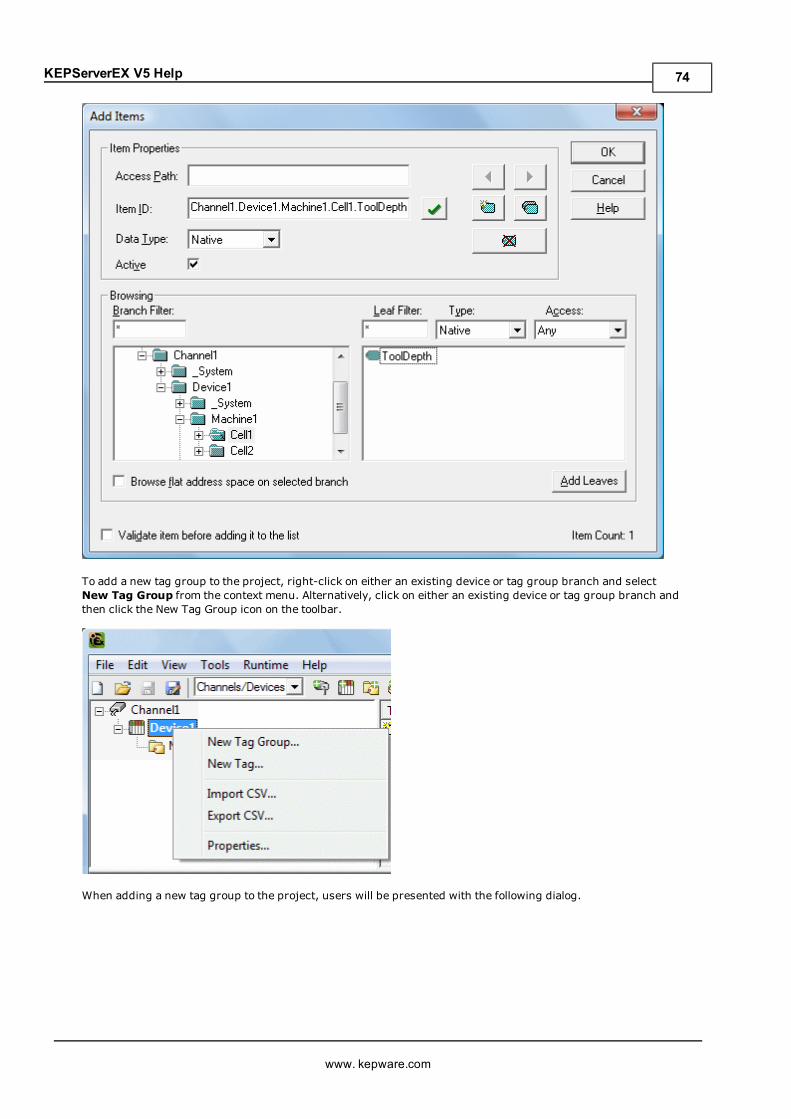
KEPServerEX V5 Help
To add a new tag group to the project, right-click on either an existing device or tag group branch and selectNew Tag Group from the context menu. Alternatively, click on either an existing device or tag group branch andthen click the New Tag Group icon on the toolbar.
When adding a new tag group to the project, users will be presented with the following dialog.
www. kepware.com
74
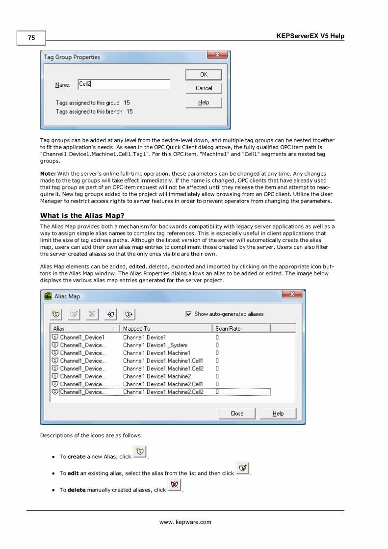
KEPServerEX V5 Help
Tag groups can be added at any level from the device-level down, and multiple tag groups can be nested togetherto fit the application's needs. As seen in the OPC Quick Client dialog above, the fully qualified OPC item path is"Channel1.Device1.Machine1.Cell1.Tag1". For this OPC item, "Machine1" and "Cell1" segments are nested taggroups.
Note:With the server's online full-time operation, these parameters can be changed at any time. Any changesmade to the tag groups will take effect immediately. If the name is changed, OPC clients that have already usedthat tag group as part of an OPC item request will not be affected until they release the item and attempt to reac-quire it. New tag groups added to the project will immediately allow browsing from an OPC client. Utilize the UserManager to restrict access rights to server features in order to prevent operators from changing the parameters.
What is the Alias Map?The Alias Map provides both a mechanism for backwards compatibility with legacy server applications as well as away to assign simple alias names to complex tag references. This is especially useful in client applications thatlimit the size of tag address paths. Although the latest version of the server will automatically create the aliasmap, users can add their own alias map entries to compliment those created by the server. Users can also filterthe server created aliases so that the only ones visible are their own.
Alias Map elements can be added, edited, deleted, exported and imported by clicking on the appropriate icon but-tons in the Alias Map window. The Alias Properties dialog allows an alias to be added or edited. The image belowdisplays the various alias map entries generated for the server project.
Descriptions of the icons are as follows.
l To create a new Alias, click .
l To edit an existing alias, select the alias from the list and then click .
l To deletemanually created aliases, click .
www. kepware.com
75
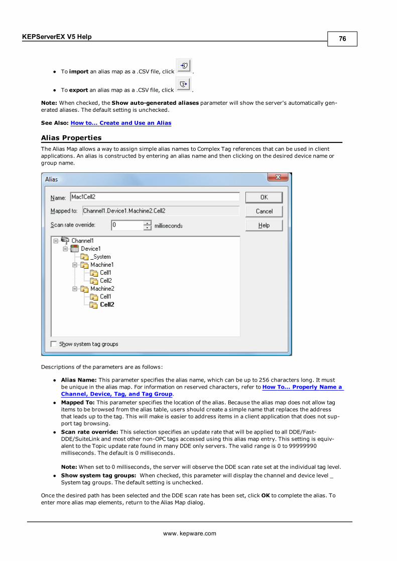
KEPServerEX V5 Help
l To import an alias map as a .CSV file, click .
l To export an alias map as a .CSV file, click .
Note: When checked, the Show auto-generated aliases parameter will show the server's automatically gen-erated aliases. The default setting is unchecked.
See Also: How to... Create and Use an Alias
Alias PropertiesThe Alias Map allows a way to assign simple alias names to Complex Tag references that can be used in clientapplications. An alias is constructed by entering an alias name and then clicking on the desired device name orgroup name.
Descriptions of the parameters are as follows:
l Alias Name: This parameter specifies the alias name, which can be up to 256 characters long. It mustbe unique in the alias map. For information on reserved characters, refer toHow To... Properly Name aChannel, Device, Tag, and Tag Group.
l Mapped To: This parameter specifies the location of the alias. Because the alias map does not allow tagitems to be browsed from the alias table, users should create a simple name that replaces the addressthat leads up to the tag. This will make is easier to address items in a client application that does not sup-port tag browsing.
l Scan rate override: This selection specifies an update rate that will be applied to all DDE/Fast-DDE/SuiteLink and most other non-OPC tags accessed using this alias map entry. This setting is equiv-alent to the Topic update rate found in many DDE only servers. The valid range is 0 to 99999990milliseconds. The default is 0 milliseconds.
Note:When set to 0 milliseconds, the server will observe the DDE scan rate set at the individual tag level.l Show system tag groups: When checked, this parameter will display the channel and device level _System tag groups. The default setting is unchecked.
Once the desired path has been selected and the DDE scan rate has been set, clickOK to complete the alias. Toenter more alias map elements, return to the Alias Map dialog.
www. kepware.com
76
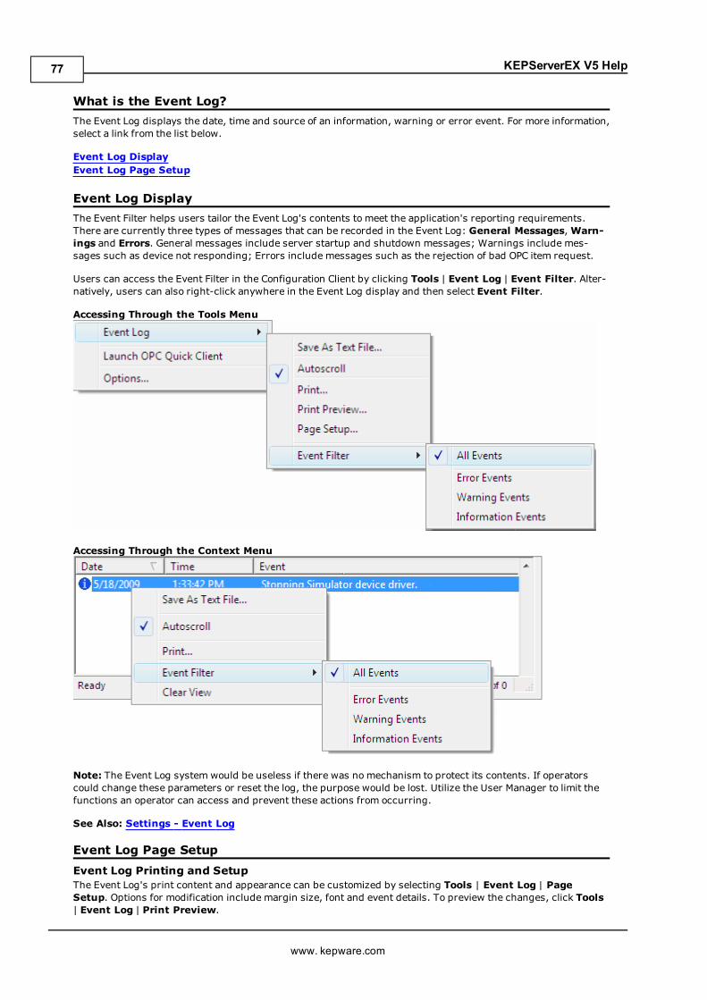
KEPServerEX V5 Help
What is the Event Log?The Event Log displays the date, time and source of an information, warning or error event. For more information,select a link from the list below.
Event Log DisplayEvent Log Page Setup
Event Log DisplayThe Event Filter helps users tailor the Event Log's contents to meet the application's reporting requirements.There are currently three types of messages that can be recorded in the Event Log: General Messages,Warn-ings and Errors. General messages include server startup and shutdown messages; Warnings include mes-sages such as device not responding; Errors include messages such as the rejection of bad OPC item request.
Users can access the Event Filter in the Configuration Client by clicking Tools | Event Log | Event Filter. Alter-natively, users can also right-click anywhere in the Event Log display and then select Event Filter.
Accessing Through the Tools Menu
Accessing Through the Context Menu
Note: The Event Log system would be useless if there was no mechanism to protect its contents. If operatorscould change these parameters or reset the log, the purpose would be lost. Utilize the User Manager to limit thefunctions an operator can access and prevent these actions from occurring.
See Also: Settings - Event Log
Event Log Page SetupEvent Log Printing and SetupThe Event Log's print content and appearance can be customized by selecting Tools | Event Log | PageSetup. Options for modification include margin size, font and event details. To preview the changes, click Tools| Event Log | Print Preview.
www. kepware.com
77
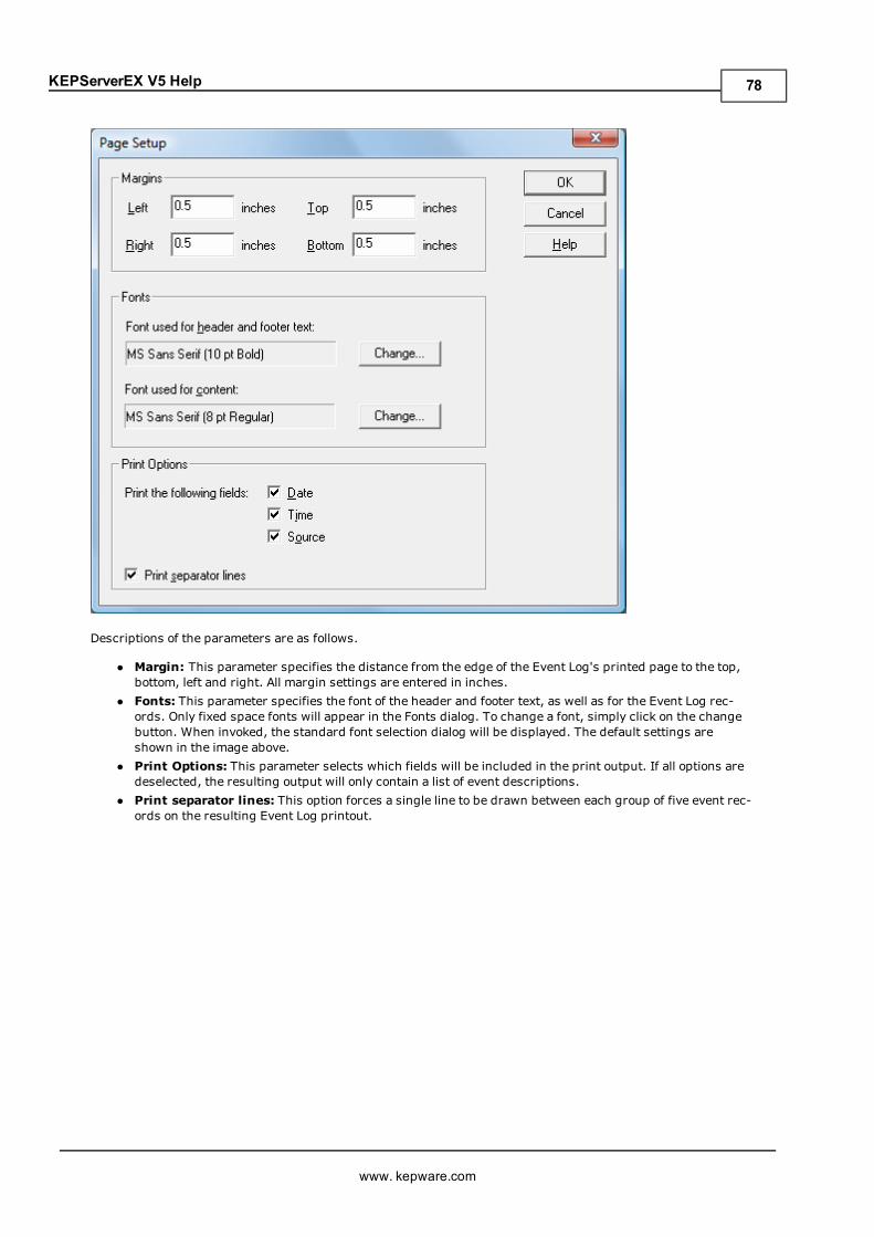
KEPServerEX V5 Help
Descriptions of the parameters are as follows.
l Margin: This parameter specifies the distance from the edge of the Event Log's printed page to the top,bottom, left and right. All margin settings are entered in inches.
l Fonts: This parameter specifies the font of the header and footer text, as well as for the Event Log rec-ords. Only fixed space fonts will appear in the Fonts dialog. To change a font, simply click on the changebutton. When invoked, the standard font selection dialog will be displayed. The default settings areshown in the image above.
l Print Options: This parameter selects which fields will be included in the print output. If all options aredeselected, the resulting output will only contain a list of event descriptions.
l Print separator lines: This option forces a single line to be drawn between each group of five event rec-ords on the resulting Event Log printout.
www. kepware.com
78
KEPServerEX V5 Help
Tag ManagementThe server's user-defined tag management features can create a tag database structure to fit each application'sspecific nature. Users can define multiple tag groups to segregate tag data on a device-by-device basis, and canalso easily add large numbers of tags through drag and drop editing. CSV import and export also allow tag editingin any application. Like all other server features, new tags can be added to the application at any time.
Automatic Tag Database GenerationThe OPC server's ability to automatically generate tags for select communication drivers brings OPC technologyone step closer to Plug and Play operation. Tag information can be read directly from a device, and tags can alsobe generated from stored tag data. In either case, users no longer need to manually enter OPC tags into theserver.
System TagsSystem Tags provide general error feedback to client applications, allow the operation control over when a deviceis actively collecting data, and also permit a channel or device's standard parameters to be changed from an OPCclient application. The number of System Tags available at the channel or device level depends on the nature ofthe driver being used.
Note: System Tags can be grouped according to their purpose as both status and control or parameter manip-ulation.
Property TagsProperty Tags are additional tags that can be accessed by any Data Access client by appending the propertyname to any fully qualified tag address. When using an OPC client that supports item browsing, users canbrowse Tag Properties by turning on Include tag properties when a client browses the server under OPCDA Settings. For more information, refer to Project Properties - OPC DA Settings.
Statistics TagsStatistics Tags provide feedback to client applications regarding the operation of the channel communications inthe server. When diagnostics are enabled, seven built-in Statistics Tags will be available. For more information,refer toOPC Diagnostics Window.
Modem TagsModem Tags configure modem properties and monitor modem status. They are only available when the Con-nection Type in Channel Properties is set toModem. For more information, refer to Channel Properties -Communications and Channel Properties - Modem.
Communication Serialization TagsDriver communications normally occur simultaneously across multiple channels, thus yielding higher datathroughput. In some applications, however, it is required that only one channel be allowed to communicate at atime. Communication Serialization provides this support. Communication Serialization Tags are used to configureand monitor a channel's serialization status. Both the feature and its tags are only available to specific drivers.For more information, refer to the driver's help documentation.
CSV Import and ExportThis server can import and export tag data in a Comma Separated Variable (CSV) file to quickly create tags in anapplication. The CSV functions are only available when a device or tag group is selected.
Note: For information on which character to specify as the variable, refer toOptions - General.
To jump to a specific section, select a link from the list below.
Exporting a Server Tag ListImporting a Server Tag List into the ServerUsing Other Characters as the Delimiter
Creating a TemplateThe easiest way to create and import CSV file is to create a template. For more information, refer to the instruc-tions below.
1. To start, click File | Export CSV. Then, define the channels and devices for the project.
2. Define a tag for each device.
www. kepware.com
79
KEPServerEX V5 Help
3. Next, export each device or tag group as a CSV file.
4. Use this template in a spreadsheet application that supports CSV files and then modify the file as desired.
Note: The resulting CSV file can be saved to disk and re-imported into the server under the same (ornew) device or tag group.
Exporting a Server Tag ListExporting a server tag list generates a .CSV text file that contains a heading record followed by a record for eachtag defined under the selected device or tag group. The heading record contains the following fields:
l Tag Name: The name of the tag as it will be referenced in an OPC client.
Note: The Tag Namemay contain a Group Name prefix that is separated from the Tag Name with a period.For example, a Tag Name of "Group1.Tag1" will create a group named "Group1" that contains "Tag1".
l Address: The device location referenced by the tag.l Data Type: The data type used for the tag as shown in the server tag's Data Type drop-down list.l Respect Data Type: This forces the tag to follow its defined data type, not the OPC client request (1, 0).l Client Access: Read/Write access (Read Only and Read/Write).l Scan Rate: The rate in milliseconds at which the tag address will be scanned when used with most non-OPC clients.
l Scaling: Scaling mode (None, Linear, and Square Root).l Raw Low: Low raw value.l Raw High: High raw value.l Scaled Low: Scaled low value.l Scaled High: Scaled high value.l Scaled Data Type: The data type used for the tag after scaling is applied.l Clamp Low: Forces the resulting scaled value to stay within the limit of Scaled Low (1, 0).l Clamp High: Forces the resulting scaled value to stay within the limit of Scaled High (1, 0).l Eng. Units: Units string.l Description: The description of the tag.l Negate Value: Negates the resulting value before being passed to the client when scaling is applied (1,0).
Note: Each tag record contains the data for each field.
Microsoft Excel is an excellent tool for editing large groups of tags outside the server. Once a template CSV filehas been exported, it can be loaded directly into Excel for editing. A CSV file load in Excel would appear as shownin the image below.
www. kepware.com
80
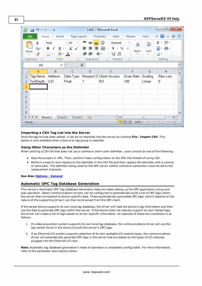
KEPServerEX V5 Help
Importing a CSV Tag List into the ServerOnce the tag list has been edited, it can be re-imported into the server by clicking File | Import CSV. Thisoption is only available when a device or tag group is selected.
Using Other Characters as the DelimiterWhen utilizing a CSV file that does not use a comma or semi-colon delimiter, users should do one of the following:
l Save the project in XML. Then, performmass configuration on the XML file instead of using CSV.l Perform a search-and-replace on the delimiter in the CSV file and then replace the delimiter with a commaor semicolon. The delimiter being used by the OPC server (either comma or semicolon) must be set to thereplacement character.
See Also: Options - General
Automatic OPC Tag Database GenerationThis server's Automatic OPC Tag Database Generation features make setting up the OPC application a plug andplay operation. Select communications drivers can be configured to automatically build a list of OPC tags withinthe server that correspond to device-specific data. These automatically generated OPC tags (which depend on thenature of the supporting driver) can then be browsed from the OPC client.
If the target device supports its own local tag database, the driver will read the device's tag information and thenuse the data to generate OPC tags within the server. If the device does not natively support its own named tags,the driver will create a list of tags based on driver-specific information. An example of these two conditions is asfollows:
1. If a data acquisition system supports its own local tag database, the communications driver will use thetag names found in the device to build the server's OPC tags.
2. If an Ethernet I/O system supports detection of its own available I/O module types, the communicationsdriver will automatically generate OPC tags in the server that are based on the types of I/O modulesplugged into the Ethernet I/O rack.
Note: Automatic tag database generation's mode of operation is completely configurable. For more information,refer to the parameter descriptions below.
www. kepware.com
81
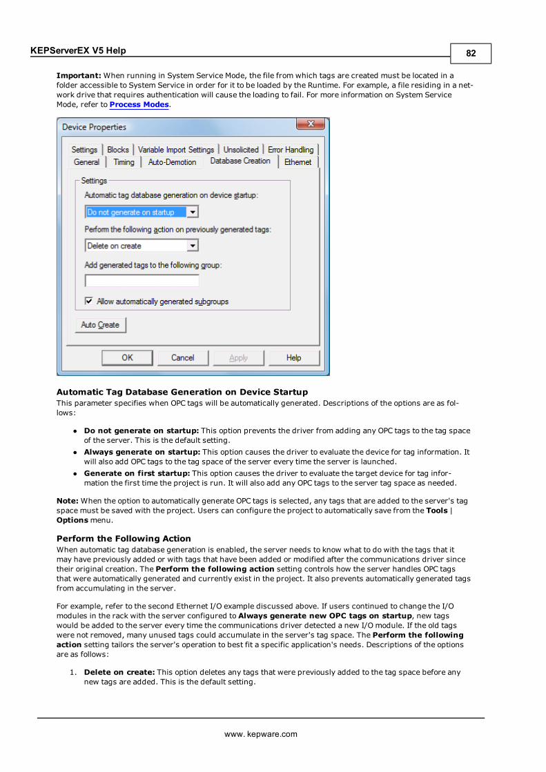
KEPServerEX V5 Help
Important:When running in System Service Mode, the file from which tags are created must be located in afolder accessible to System Service in order for it to be loaded by the Runtime. For example, a file residing in a net-work drive that requires authentication will cause the loading to fail. For more information on System ServiceMode, refer to Process Modes.
Automatic Tag Database Generation on Device StartupThis parameter specifies when OPC tags will be automatically generated. Descriptions of the options are as fol-lows:
l Do not generate on startup: This option prevents the driver from adding any OPC tags to the tag spaceof the server. This is the default setting.
l Always generate on startup: This option causes the driver to evaluate the device for tag information. Itwill also add OPC tags to the tag space of the server every time the server is launched.
l Generate on first startup: This option causes the driver to evaluate the target device for tag infor-mation the first time the project is run. It will also add any OPC tags to the server tag space as needed.
Note:When the option to automatically generate OPC tags is selected, any tags that are added to the server's tagspace must be saved with the project. Users can configure the project to automatically save from the Tools |Optionsmenu.
Perform the Following ActionWhen automatic tag database generation is enabled, the server needs to know what to do with the tags that itmay have previously added or with tags that have been added or modified after the communications driver sincetheir original creation. The Perform the following action setting controls how the server handles OPC tagsthat were automatically generated and currently exist in the project. It also prevents automatically generated tagsfrom accumulating in the server.
For example, refer to the second Ethernet I/O example discussed above. If users continued to change the I/Omodules in the rack with the server configured to Always generate new OPC tags on startup, new tagswould be added to the server every time the communications driver detected a new I/O module. If the old tagswere not removed, many unused tags could accumulate in the server's tag space. The Perform the followingaction setting tailors the server's operation to best fit a specific application's needs. Descriptions of the optionsare as follows:
1. Delete on create: This option deletes any tags that were previously added to the tag space before anynew tags are added. This is the default setting.
www. kepware.com
82
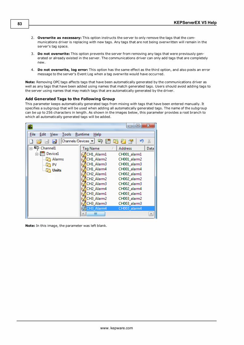
KEPServerEX V5 Help
2. Overwrite as necessary: This option instructs the server to only remove the tags that the com-munications driver is replacing with new tags. Any tags that are not being overwritten will remain in theserver's tag space.
3. Do not overwrite: This option prevents the server from removing any tags that were previously gen-erated or already existed in the server. The communications driver can only add tags that are completelynew.
4. Do not overwrite, log error: This option has the same effect as the third option, and also posts an errormessage to the server's Event Log when a tag overwrite would have occurred.
Note: Removing OPC tags affects tags that have been automatically generated by the communications driver aswell as any tags that have been added using names that match generated tags. Users should avoid adding tags tothe server using names that may match tags that are automatically generated by the driver.
Add Generated Tags to the Following GroupThis parameter keeps automatically generated tags frommixing with tags that have been entered manually. Itspecifies a subgroup that will be used when adding all automatically generated tags. The name of the subgroupcan be up to 256 characters in length. As shown in the images below, this parameter provides a root branch towhich all automatically generated tags will be added.
Note: In this image, the parameter was left blank.
www. kepware.com
83
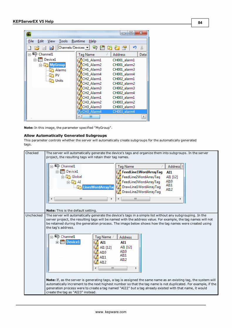
KEPServerEX V5 Help
Note: In this image, the parameter specified "MyGroup".
Allow Automatically Generated SubgroupsThis parameter controls whether the server will automatically create subgroups for the automatically generatedtags.
Checked The server will automatically generate the device's tags and organize them into subgroups. In the serverproject, the resulting tags will retain their tag names.
Note: This is the default setting.Unchecked The server will automatically generate the device's tags in a simple list without any subgrouping. In the
server project, the resulting tags will be named with the address value. For example, the tag names will notbe retained during the generation process. The image below shows how the tag names were created usingthe tag's address.
Note: If, as the server is generating tags, a tag is assigned the same name as an existing tag, the system willautomatically increment to the next highest number so that the tag name is not duplicated. For example, if thegeneration process were to create a tag named "AI22" but a tag already existed with that name, it wouldcreate the tag as "AI23" instead.
www. kepware.com
84
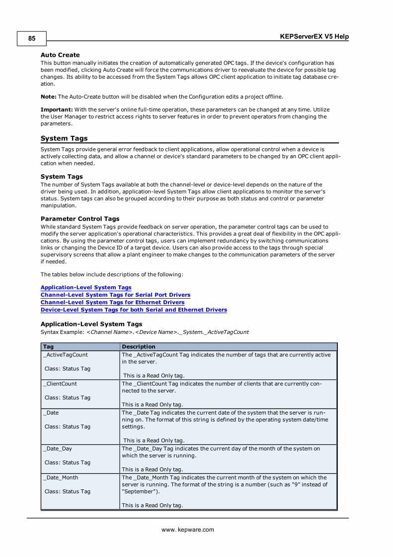
KEPServerEX V5 Help
Auto CreateThis button manually initiates the creation of automatically generated OPC tags. If the device's configuration hasbeen modified, clicking Auto Create will force the communications driver to reevaluate the device for possible tagchanges. Its ability to be accessed from the System Tags allows OPC client application to initiate tag database cre-ation.
Note: The Auto-Create button will be disabled when the Configuration edits a project offline.
Important:With the server's online full-time operation, these parameters can be changed at any time. Utilizethe User Manager to restrict access rights to server features in order to prevent operators from changing theparameters.
System TagsSystem Tags provide general error feedback to client applications, allow operational control when a device isactively collecting data, and allow a channel or device's standard parameters to be changed by an OPC client appli-cation when needed.
System TagsThe number of System Tags available at both the channel-level or device-level depends on the nature of thedriver being used. In addition, application-level System Tags allow client applications to monitor the server'sstatus. System tags can also be grouped according to their purpose as both status and control or parametermanipulation.
Parameter Control TagsWhile standard System Tags provide feedback on server operation, the parameter control tags can be used tomodify the server application's operational characteristics. This provides a great deal of flexibility in the OPC appli-cations. By using the parameter control tags, users can implement redundancy by switching communicationslinks or changing the Device ID of a target device. Users can also provide access to the tags through specialsupervisory screens that allow a plant engineer to make changes to the communication parameters of the serverif needed.
The tables below include descriptions of the following:
Application-Level System TagsChannel-Level System Tags for Serial Port DriversChannel-Level System Tags for Ethernet DriversDevice-Level System Tags for both Serial and Ethernet Drivers
Application-Level System TagsSyntax Example: <Channel Name>.<Device Name>._System._ActiveTagCount
Tag Description_ActiveTagCount
Class: Status Tag
The _ActiveTagCount Tag indicates the number of tags that are currently activein the server.
This is a Read Only tag._ClientCount
Class: Status Tag
The _ClientCount Tag indicates the number of clients that are currently con-nected to the server.
This is a Read Only tag._Date
Class: Status Tag
The _Date Tag indicates the current date of the system that the server is run-ning on. The format of this string is defined by the operating system date/timesettings.
This is a Read Only tag._Date_Day
Class: Status Tag
The _Date_Day Tag indicates the current day of the month of the system onwhich the server is running.
This is a Read Only tag._Date_Month
Class: Status Tag
The _Date_Month Tag indicates the current month of the system on which theserver is running. The format of the string is a number (such as "9" instead of"September").
This is a Read Only tag.
www. kepware.com
85
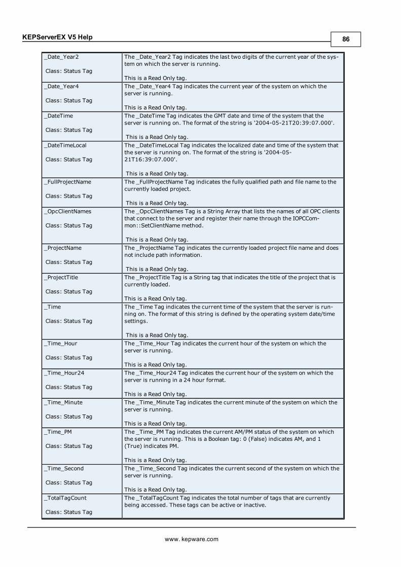
KEPServerEX V5 Help
_Date_Year2
Class: Status Tag
The _Date_Year2 Tag indicates the last two digits of the current year of the sys-tem on which the server is running.
This is a Read Only tag._Date_Year4
Class: Status Tag
The _Date_Year4 Tag indicates the current year of the system on which theserver is running.
This is a Read Only tag._DateTime
Class: Status Tag
The _DateTime Tag indicates the GMT date and time of the system that theserver is running on. The format of the string is '2004-05-21T20:39:07.000'.
This is a Read Only tag._DateTimeLocal
Class: Status Tag
The _DateTimeLocal Tag indicates the localized date and time of the system thatthe server is running on. The format of the string is '2004-05-21T16:39:07.000'.
This is a Read Only tag._FullProjectName
Class: Status Tag
The _FullProjectName Tag indicates the fully qualified path and file name to thecurrently loaded project.
This is a Read Only tag._OpcClientNames
Class: Status Tag
The _OpcClientNames Tag is a String Array that lists the names of all OPC clientsthat connect to the server and register their name through the IOPCCom-mon::SetClientNamemethod.
This is a Read Only tag._ProjectName
Class: Status Tag
The _ProjectName Tag indicates the currently loaded project file name and doesnot include path information.
This is a Read Only tag._ProjectTitle
Class: Status Tag
The _ProjectTitle Tag is a String tag that indicates the title of the project that iscurrently loaded.
This is a Read Only tag._Time
Class: Status Tag
The _Time Tag indicates the current time of the system that the server is run-ning on. The format of this string is defined by the operating system date/timesettings.
This is a Read Only tag._Time_Hour
Class: Status Tag
The _Time_Hour Tag indicates the current hour of the system on which theserver is running.
This is a Read Only tag._Time_Hour24
Class: Status Tag
The _Time_Hour24 Tag indicates the current hour of the system on which theserver is running in a 24 hour format.
This is a Read Only tag._Time_Minute
Class: Status Tag
The _Time_Minute Tag indicates the current minute of the system on which theserver is running.
This is a Read Only tag._Time_PM
Class: Status Tag
The _Time_PM Tag indicates the current AM/PM status of the system on whichthe server is running. This is a Boolean tag: 0 (False) indicates AM, and 1(True) indicates PM.
This is a Read Only tag._Time_Second
Class: Status Tag
The _Time_Second Tag indicates the current second of the system on which theserver is running.
This is a Read Only tag._TotalTagCount
Class: Status Tag
The _TotalTagCount Tag indicates the total number of tags that are currentlybeing accessed. These tags can be active or inactive.
www. kepware.com
86
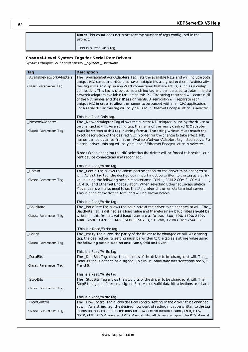
KEPServerEX V5 Help
Note: This count does not represent the number of tags configured in theproject.
This is a Read Only tag.
Channel-Level System Tags for Serial Port DriversSyntax Example: <Channel name>._System._BaudRate
Tag Description_AvailableNetworkAdapters
Class: Parameter Tag
The _AvailableNetworkAdapters Tag lists the available NICs and will include bothunique NIC cards and NICs that have multiple IPs assigned to them. Additionallythis tag will also display any WAN connections that are active, such as a dialupconnection. This tag is provided as a string tag and can be used to determine thenetwork adapters available for use on this PC. The string returned will contain allof the NIC names and their IP assignments. A semicolon will separate eachunique NIC in order to allow the names to be parsed within an OPC application.For a serial driver this tag will only be used if Ethernet Encapsulation is selected.
This is a Read Only tag._NetworkAdapter
Class: Parameter Tag
The _NetworkAdapter Tag allows the current NIC adapter in use by the driver tobe changed at will. As a string tag, the name of the newly desired NIC adaptermust be written to this tag in string format. The string written must match theexact description of the desired NIC in order for the change to take effect. NICnames can be obtained from the _AvailableNetworkAdapters tag listed above. Fora serial driver, this tag will only be used if Ethernet Encapsulation is selected.
Note: When changing the NIC selection the driver will be forced to break all cur-rent device connections and reconnect.
This is a Read/Write tag._ComId
Class: Parameter Tag
The _ComId Tag allows the comm port selection for the driver to be changed atwill. As a string tag, the desired comm port must be written to the tag as a stringvalue using the following possible selections: COM 1, COM 2 COM 3, COM 4, - - -,COM 16, and Ethernet Encapsulation. When selecting Ethernet EncapsulationMode, users will also need to set the IP number of the remote terminal server.This is done at the device-level and will be shown below.
This is a Read/Write tag._BaudRate
Class: Parameter Tag
The _BaudRate Tag allows the baud rate of the driver to be changed at will. The _BaudRate Tag is defined as a long value and therefore new baud rates should bewritten in this format. Valid baud rates are as follows: 300, 600, 1200, 2400,4800, 9600, 19200, 38400, 56000, 56700, 115200, 128000 and 256000.
This is a Read/Write tag._Parity
Class: Parameter Tag
The _Parity Tag allows the parity of the driver to be changed at will. As a stringtag, the desired parity setting must be written to the tag as a string value usingthe following possible selections: None, Odd and Even.
This is a Read/Write tag._DataBits
Class: Parameter Tag
The _DataBits Tag allows the data bits of the driver to be changed at will. The _DataBits tag is defined as a signed 8 bit value. Valid data bits selections are 5, 6,7 and 8.
This is a Read/Write tag._StopBits
Class: Parameter Tag
The _StopBits Tag allows the stop bits of the driver to be changed at will. The _StopBits tag is defined as a signed 8 bit value. Valid data bit selections are 1 and2.
This is a Read/Write tag._FlowControl
Class: Parameter Tag
The _FlowControl Tag allows the flow control setting of the driver to be changedat will. As a string tag, the desired flow control setting must be written to the tagin this format. Possible selections for flow control include: None, DTR, RTS,"DTR,RTS", RTS Always and RTS Manual. Not all drivers support the RTS Manual
www. kepware.com
87
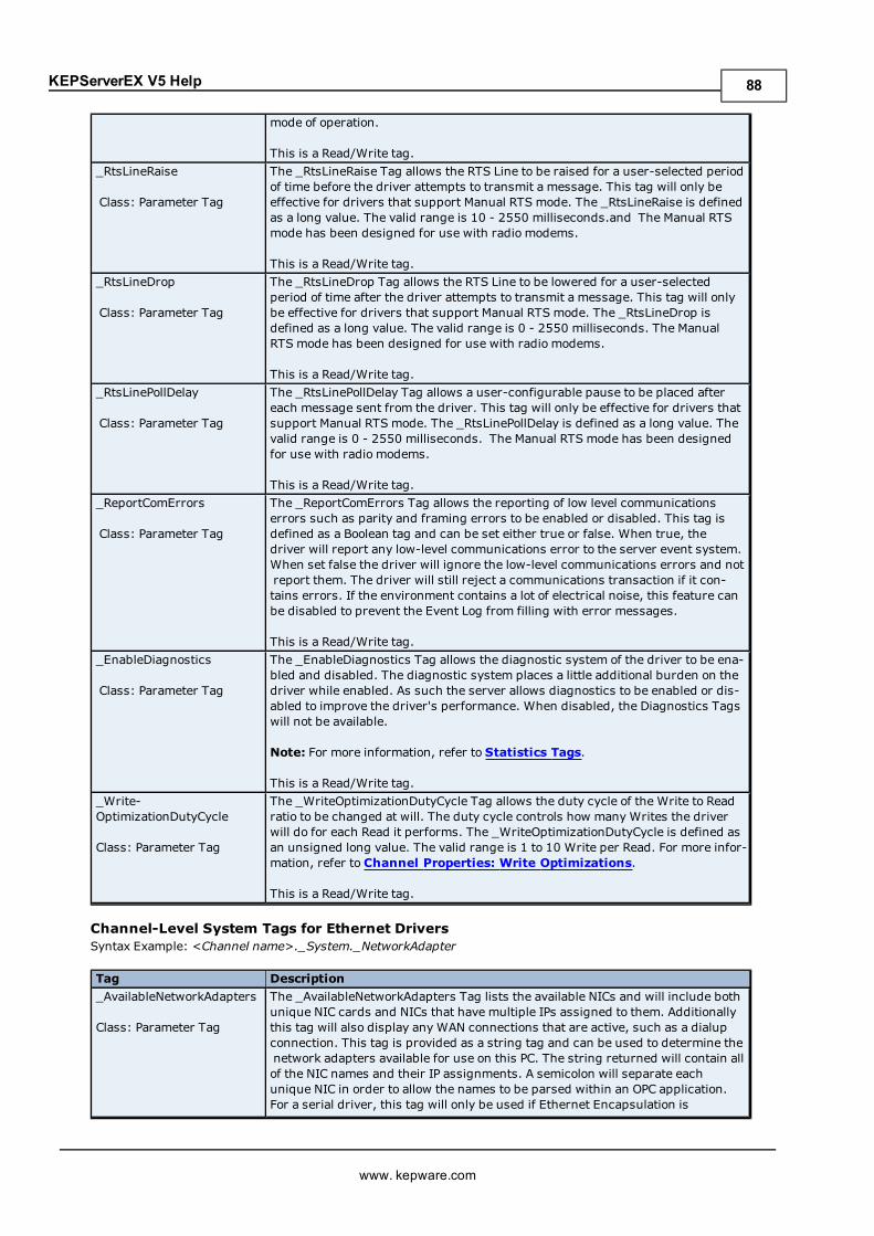
KEPServerEX V5 Help
mode of operation.
This is a Read/Write tag._RtsLineRaise
Class: Parameter Tag
The _RtsLineRaise Tag allows the RTS Line to be raised for a user-selected periodof time before the driver attempts to transmit a message. This tag will only beeffective for drivers that support Manual RTS mode. The _RtsLineRaise is definedas a long value. The valid range is 10 - 2550 milliseconds.and The Manual RTSmode has been designed for use with radio modems.
This is a Read/Write tag._RtsLineDrop
Class: Parameter Tag
The _RtsLineDrop Tag allows the RTS Line to be lowered for a user-selectedperiod of time after the driver attempts to transmit a message. This tag will onlybe effective for drivers that support Manual RTS mode. The _RtsLineDrop isdefined as a long value. The valid range is 0 - 2550 milliseconds. The ManualRTS mode has been designed for use with radio modems.
This is a Read/Write tag._RtsLinePollDelay
Class: Parameter Tag
The _RtsLinePollDelay Tag allows a user-configurable pause to be placed aftereach message sent from the driver. This tag will only be effective for drivers thatsupport Manual RTS mode. The _RtsLinePollDelay is defined as a long value. Thevalid range is 0 - 2550 milliseconds. The Manual RTS mode has been designedfor use with radio modems.
This is a Read/Write tag._ReportComErrors
Class: Parameter Tag
The _ReportComErrors Tag allows the reporting of low level communicationserrors such as parity and framing errors to be enabled or disabled. This tag isdefined as a Boolean tag and can be set either true or false. When true, thedriver will report any low-level communications error to the server event system.When set false the driver will ignore the low-level communications errors and notreport them. The driver will still reject a communications transaction if it con-tains errors. If the environment contains a lot of electrical noise, this feature canbe disabled to prevent the Event Log from filling with error messages.
This is a Read/Write tag._EnableDiagnostics
Class: Parameter Tag
The _EnableDiagnostics Tag allows the diagnostic system of the driver to be ena-bled and disabled. The diagnostic system places a little additional burden on thedriver while enabled. As such the server allows diagnostics to be enabled or dis-abled to improve the driver's performance. When disabled, the Diagnostics Tagswill not be available.
Note: For more information, refer to Statistics Tags.
This is a Read/Write tag._Write-OptimizationDutyCycle
Class: Parameter Tag
The _WriteOptimizationDutyCycle Tag allows the duty cycle of the Write to Readratio to be changed at will. The duty cycle controls how many Writes the driverwill do for each Read it performs. The _WriteOptimizationDutyCycle is defined asan unsigned long value. The valid range is 1 to 10 Write per Read. For more infor-mation, refer to Channel Properties: Write Optimizations.
This is a Read/Write tag.
Channel-Level System Tags for Ethernet DriversSyntax Example: <Channel name>._System._NetworkAdapter
Tag Description_AvailableNetworkAdapters
Class: Parameter Tag
The _AvailableNetworkAdapters Tag lists the available NICs and will include bothunique NIC cards and NICs that have multiple IPs assigned to them. Additionallythis tag will also display any WAN connections that are active, such as a dialupconnection. This tag is provided as a string tag and can be used to determine thenetwork adapters available for use on this PC. The string returned will contain allof the NIC names and their IP assignments. A semicolon will separate eachunique NIC in order to allow the names to be parsed within an OPC application.For a serial driver, this tag will only be used if Ethernet Encapsulation is
www. kepware.com
88
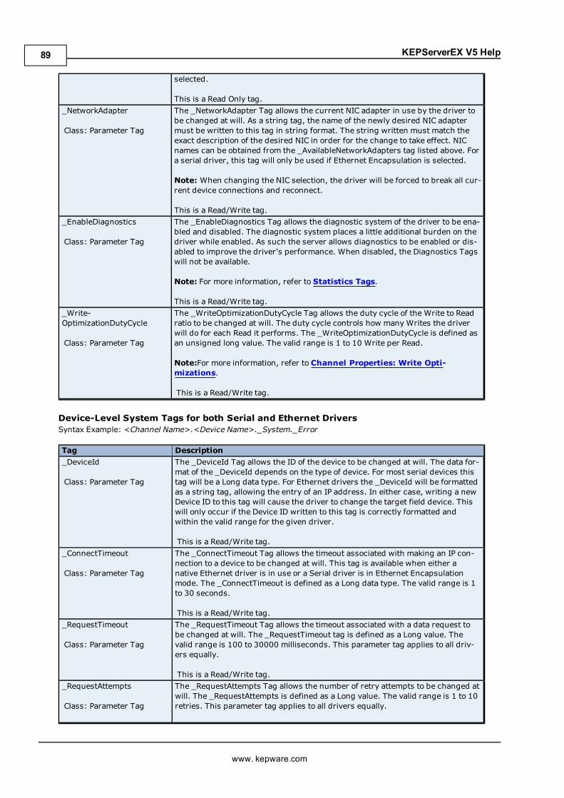
KEPServerEX V5 Help
selected.
This is a Read Only tag._NetworkAdapter
Class: Parameter Tag
The _NetworkAdapter Tag allows the current NIC adapter in use by the driver tobe changed at will. As a string tag, the name of the newly desired NIC adaptermust be written to this tag in string format. The string written must match theexact description of the desired NIC in order for the change to take effect. NICnames can be obtained from the _AvailableNetworkAdapters tag listed above. Fora serial driver, this tag will only be used if Ethernet Encapsulation is selected.
Note: When changing the NIC selection, the driver will be forced to break all cur-rent device connections and reconnect.
This is a Read/Write tag._EnableDiagnostics
Class: Parameter Tag
The _EnableDiagnostics Tag allows the diagnostic system of the driver to be ena-bled and disabled. The diagnostic system places a little additional burden on thedriver while enabled. As such the server allows diagnostics to be enabled or dis-abled to improve the driver's performance. When disabled, the Diagnostics Tagswill not be available.
Note: For more information, refer to Statistics Tags.
This is a Read/Write tag._Write-OptimizationDutyCycle
Class: Parameter Tag
The _WriteOptimizationDutyCycle Tag allows the duty cycle of the Write to Readratio to be changed at will. The duty cycle controls how many Writes the driverwill do for each Read it performs. The _WriteOptimizationDutyCycle is defined asan unsigned long value. The valid range is 1 to 10 Write per Read.
Note:For more information, refer to Channel Properties: Write Opti-mizations.
This is a Read/Write tag.
Device-Level System Tags for both Serial and Ethernet DriversSyntax Example: <Channel Name>.<Device Name>._System._Error
Tag Description_DeviceId
Class: Parameter Tag
The _DeviceId Tag allows the ID of the device to be changed at will. The data for-mat of the _DeviceId depends on the type of device. For most serial devices thistag will be a Long data type. For Ethernet drivers the _DeviceId will be formattedas a string tag, allowing the entry of an IP address. In either case, writing a newDevice ID to this tag will cause the driver to change the target field device. Thiswill only occur if the Device ID written to this tag is correctly formatted andwithin the valid range for the given driver.
This is a Read/Write tag._ConnectTimeout
Class: Parameter Tag
The _ConnectTimeout Tag allows the timeout associated with making an IP con-nection to a device to be changed at will. This tag is available when either anative Ethernet driver is in use or a Serial driver is in Ethernet Encapsulationmode. The _ConnectTimeout is defined as a Long data type. The valid range is 1to 30 seconds.
This is a Read/Write tag._RequestTimeout
Class: Parameter Tag
The _RequestTimeout Tag allows the timeout associated with a data request tobe changed at will. The _RequestTimeout tag is defined as a Long value. Thevalid range is 100 to 30000 milliseconds. This parameter tag applies to all driv-ers equally.
This is a Read/Write tag._RequestAttempts
Class: Parameter Tag
The _RequestAttempts Tag allows the number of retry attempts to be changed atwill. The _RequestAttempts is defined as a Long value. The valid range is 1 to 10retries. This parameter tag applies to all drivers equally.
www. kepware.com
89
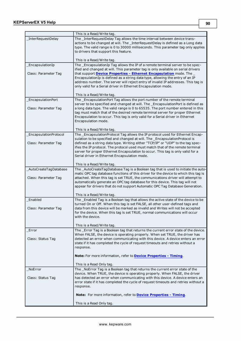
KEPServerEX V5 Help
This is a Read/Write tag._InterRequestDelay The _InterRequestDelay Tag allows the time interval between device trans-
actions to be changed at will. The _InterRequestDelay is defined as a Long datatype. The valid range is 0 to 30000 milliseconds. This parameter tag only appliesto drivers that support this feature.
This is a Read/Write tag._EncapsulationIp
Class: Parameter Tag
The _EncapsulationIp Tag allows the IP of a remote terminal server to be spec-ified and changed at will. This parameter tag is only available on serial driversthat support Device Properties - Ethernet Encapsulation mode. The _EncapsulationIp is defined as a string data type, allowing the entry of an IPaddress number. The server will reject entry of invalid IP addresses. This tag isonly valid for a Serial driver in Ethernet Encapsulation mode.
This is a Read/Write tag._EncapsulationPort
Class: Parameter Tag
The _EncapsulationPort Tag allows the port number of the remote terminalserver to be specified and changed at will. The _EncapsulationPort is defined asa long data type. The valid range is 0 to 65535. The port number entered in thistag must match that of the desired remote terminal server for proper EthernetEncapsulation to occur. This tag is only valid for a Serial driver in EthernetEncapsulation mode.
This is a Read/Write tag._EncapsulationProtocol
Class: Parameter Tag
The _EncapsulationProtocol Tag allows the IP protocol used for Ethernet Encap-sulation to be specified and changed at will. The _EncapsulationProtocol isdefined as a string data type. Writing either "TCP/IP" or "UDP" to the tag spec-ifies the IP protocol. The protocol used must match that of the remote terminalserver for proper Ethernet Encapsulation to occur. This tag is only valid for aSerial driver in Ethernet Encapsulation mode.
This is a Read/Write tag._AutoCreateTagDatabase
Class: Parameter Tag
The _AutoCreateTagDatabase Tag is a Boolean tag that is used to initiate the auto-matic OPC tag database functions of this driver for the device to which this tag isattached. When this tag is set TRUE, the communications driver will attempt toautomatically generate an OPC tag database for this device. This tag will notappear for drivers that do not support Automatic OPC Tag Database Generation.
This is a Read/Write tag._Enabled
Class: Parameter Tag
The _Enabled Tag is a Boolean tag that allows the active state of the device to beturned On or Off. When this tag is set FALSE, all other user-defined tags anddata from this device will be marked as invalid and Writes will not be acceptedfor the device. When this tag is set TRUE, normal communications will occurwith the device.
This is a Read/Write tag._Error
Class: Status Tag
The _Error Tag is a Boolean tag that returns the current error state of the device.When FALSE, the device is operating properly. When set TRUE, the driver hasdetected an error when communicating with this device. A device enters an errorstate if it has completed the cycle of request timeouts and retries without aresponse.
Note: For more information, refer toDevice Properties - Timing.
This is a Read Only tag._NoError
Class: Status Tag
The _NoError Tag is a Boolean tag that returns the current error state of thedevice. When TRUE, the device is operating properly. When FALSE, the driverhas detected an error when communicating with this device. A device enters anerror state if it has completed the cycle of request timeouts and retries without aresponse.
Note: For more information, refer toDevice Properties - Timing.
This is a Read Only tag.
www. kepware.com
90
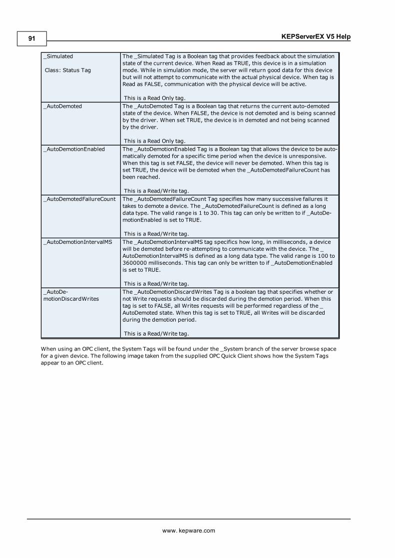
KEPServerEX V5 Help
_Simulated
Class: Status Tag
The _Simulated Tag is a Boolean tag that provides feedback about the simulationstate of the current device. When Read as TRUE, this device is in a simulationmode. While in simulation mode, the server will return good data for this devicebut will not attempt to communicate with the actual physical device. When tag isRead as FALSE, communication with the physical device will be active.
This is a Read Only tag._AutoDemoted The _AutoDemoted Tag is a Boolean tag that returns the current auto-demoted
state of the device. When FALSE, the device is not demoted and is being scannedby the driver. When set TRUE, the device is in demoted and not being scannedby the driver.
This is a Read Only tag._AutoDemotionEnabled The _AutoDemotionEnabled Tag is a Boolean tag that allows the device to be auto-
matically demoted for a specific time period when the device is unresponsive.When this tag is set FALSE, the device will never be demoted. When this tag isset TRUE, the device will be demoted when the _AutoDemotedFailureCount hasbeen reached.
This is a Read/Write tag._AutoDemotedFailureCount The _AutoDemotedFailureCount Tag specifies how many successive failures it
takes to demote a device. The _AutoDemotedFailureCount is defined as a longdata type. The valid range is 1 to 30. This tag can only be written to if _AutoDe-motionEnabled is set to TRUE.
This is a Read/Write tag._AutoDemotionIntervalMS The _AutoDemotionIntervalMS tag specifics how long, in milliseconds, a device
will be demoted before re-attempting to communicate with the device. The _AutoDemotionIntervalMS is defined as a long data type. The valid range is 100 to3600000 milliseconds. This tag can only be written to if _AutoDemotionEnabledis set to TRUE.
This is a Read/Write tag._AutoDe-motionDiscardWrites
The _AutoDemotionDiscardWrites Tag is a boolean tag that specifies whether ornot Write requests should be discarded during the demotion period. When thistag is set to FALSE, all Writes requests will be performed regardless of the _AutoDemoted state. When this tag is set to TRUE, all Writes will be discardedduring the demotion period.
This is a Read/Write tag.
When using an OPC client, the System Tags will be found under the _System branch of the server browse spacefor a given device. The following image taken from the supplied OPC Quick Client shows how the System Tagsappear to an OPC client.
www. kepware.com
91
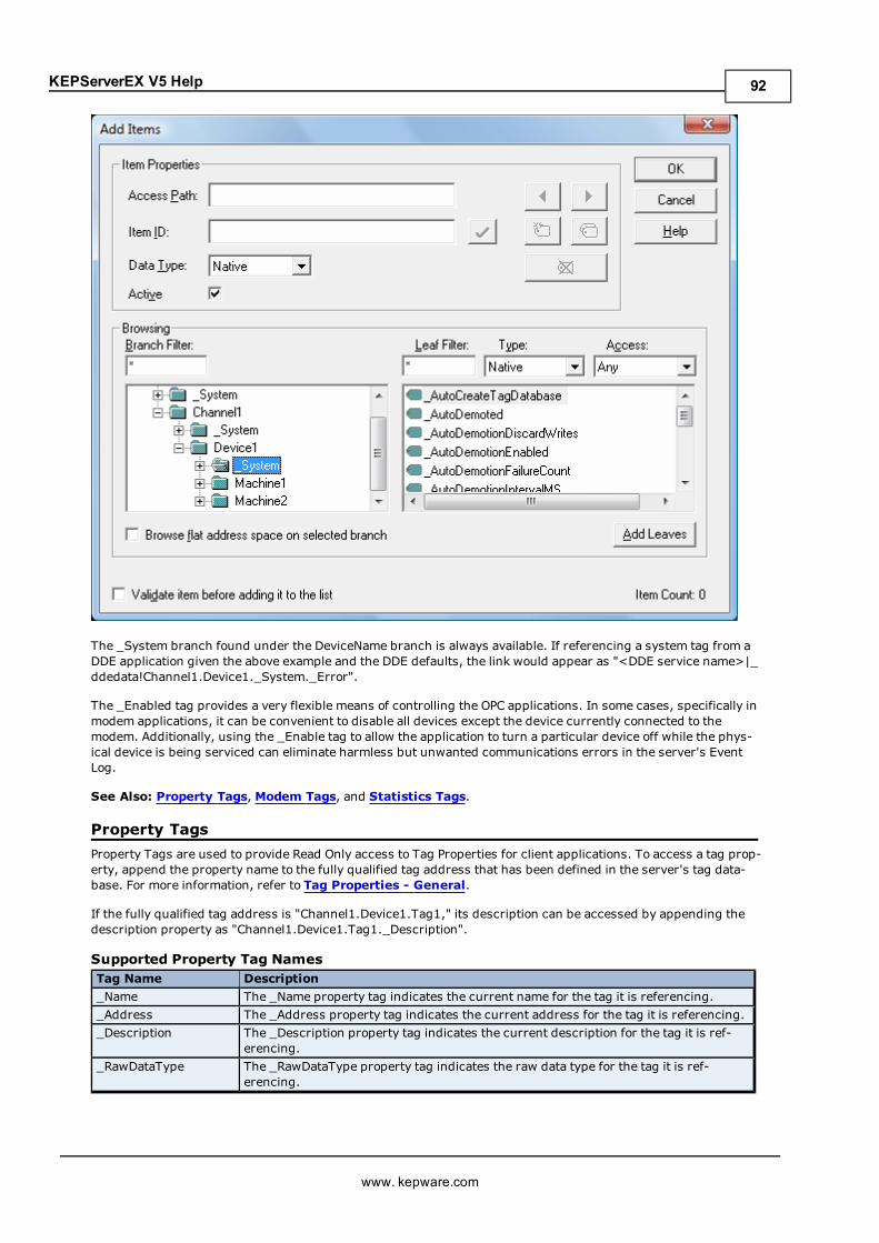
KEPServerEX V5 Help
The _System branch found under the DeviceName branch is always available. If referencing a system tag from aDDE application given the above example and the DDE defaults, the link would appear as "<DDE service name>|_ddedata!Channel1.Device1._System._Error".
The _Enabled tag provides a very flexible means of controlling the OPC applications. In some cases, specifically inmodem applications, it can be convenient to disable all devices except the device currently connected to themodem. Additionally, using the _Enable tag to allow the application to turn a particular device off while the phys-ical device is being serviced can eliminate harmless but unwanted communications errors in the server's EventLog.
See Also: Property Tags, Modem Tags, and Statistics Tags.
Property TagsProperty Tags are used to provide Read Only access to Tag Properties for client applications. To access a tag prop-erty, append the property name to the fully qualified tag address that has been defined in the server's tag data-base. For more information, refer to Tag Properties - General.
If the fully qualified tag address is "Channel1.Device1.Tag1," its description can be accessed by appending thedescription property as "Channel1.Device1.Tag1._Description".
Supported Property Tag NamesTag Name Description_Name The _Name property tag indicates the current name for the tag it is referencing._Address The _Address property tag indicates the current address for the tag it is referencing._Description The _Description property tag indicates the current description for the tag it is ref-
erencing._RawDataType The _RawDataType property tag indicates the raw data type for the tag it is ref-
erencing.
www. kepware.com
92
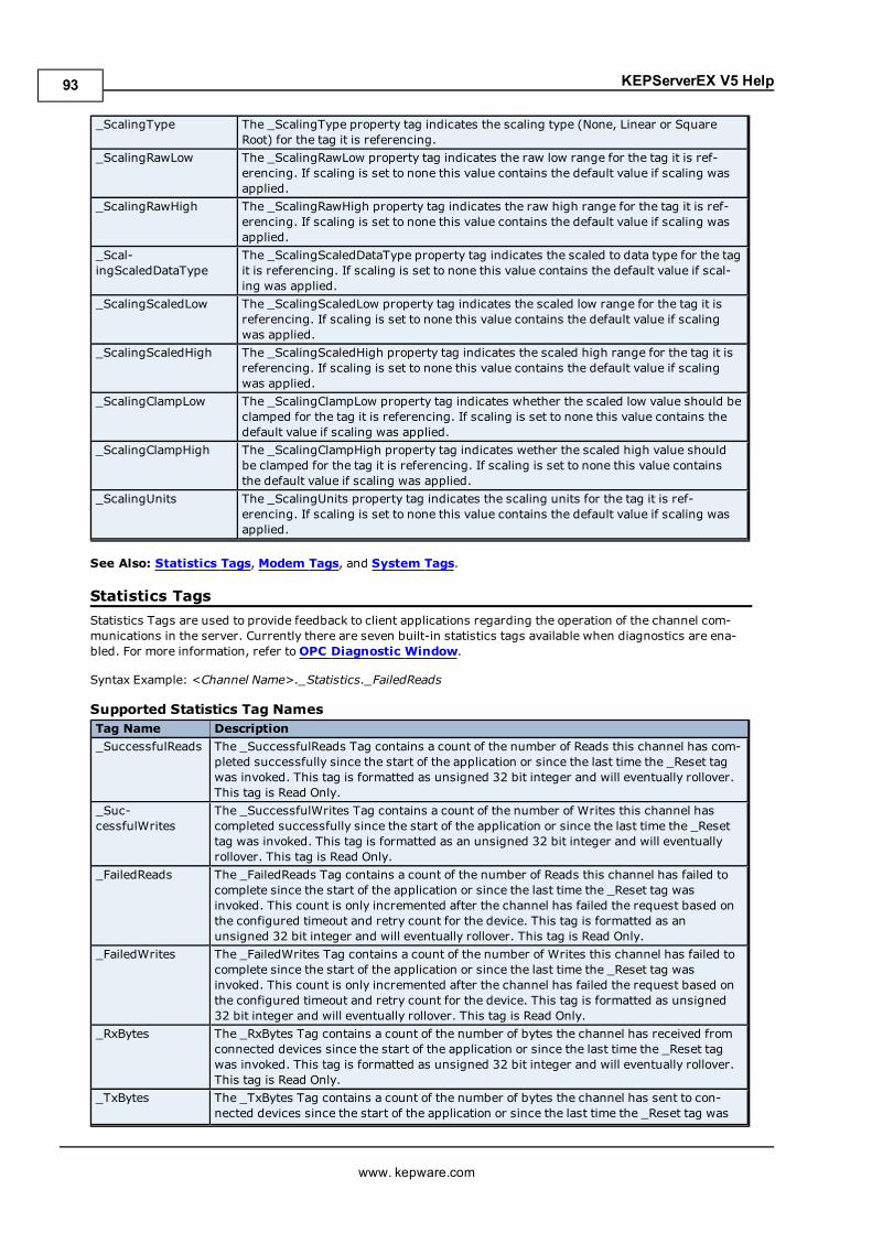
KEPServerEX V5 Help
_ScalingType The _ScalingType property tag indicates the scaling type (None, Linear or SquareRoot) for the tag it is referencing.
_ScalingRawLow The _ScalingRawLow property tag indicates the raw low range for the tag it is ref-erencing. If scaling is set to none this value contains the default value if scaling wasapplied.
_ScalingRawHigh The _ScalingRawHigh property tag indicates the raw high range for the tag it is ref-erencing. If scaling is set to none this value contains the default value if scaling wasapplied.
_Scal-ingScaledDataType
The _ScalingScaledDataType property tag indicates the scaled to data type for the tagit is referencing. If scaling is set to none this value contains the default value if scal-ing was applied.
_ScalingScaledLow The _ScalingScaledLow property tag indicates the scaled low range for the tag it isreferencing. If scaling is set to none this value contains the default value if scalingwas applied.
_ScalingScaledHigh The _ScalingScaledHigh property tag indicates the scaled high range for the tag it isreferencing. If scaling is set to none this value contains the default value if scalingwas applied.
_ScalingClampLow The _ScalingClampLow property tag indicates whether the scaled low value should beclamped for the tag it is referencing. If scaling is set to none this value contains thedefault value if scaling was applied.
_ScalingClampHigh The _ScalingClampHigh property tag indicates wether the scaled high value shouldbe clamped for the tag it is referencing. If scaling is set to none this value containsthe default value if scaling was applied.
_ScalingUnits The _ScalingUnits property tag indicates the scaling units for the tag it is ref-erencing. If scaling is set to none this value contains the default value if scaling wasapplied.
See Also: Statistics Tags, Modem Tags, and System Tags.
Statistics TagsStatistics Tags are used to provide feedback to client applications regarding the operation of the channel com-munications in the server. Currently there are seven built-in statistics tags available when diagnostics are ena-bled. For more information, refer toOPC Diagnostic Window.
Syntax Example: <Channel Name>._Statistics._FailedReads
Supported Statistics Tag NamesTag Name Description_SuccessfulReads The _SuccessfulReads Tag contains a count of the number of Reads this channel has com-
pleted successfully since the start of the application or since the last time the _Reset tagwas invoked. This tag is formatted as unsigned 32 bit integer and will eventually rollover.This tag is Read Only.
_Suc-cessfulWrites
The _SuccessfulWrites Tag contains a count of the number of Writes this channel hascompleted successfully since the start of the application or since the last time the _Resettag was invoked. This tag is formatted as an unsigned 32 bit integer and will eventuallyrollover. This tag is Read Only.
_FailedReads The _FailedReads Tag contains a count of the number of Reads this channel has failed tocomplete since the start of the application or since the last time the _Reset tag wasinvoked. This count is only incremented after the channel has failed the request based onthe configured timeout and retry count for the device. This tag is formatted as anunsigned 32 bit integer and will eventually rollover. This tag is Read Only.
_FailedWrites The _FailedWrites Tag contains a count of the number of Writes this channel has failed tocomplete since the start of the application or since the last time the _Reset tag wasinvoked. This count is only incremented after the channel has failed the request based onthe configured timeout and retry count for the device. This tag is formatted as unsigned32 bit integer and will eventually rollover. This tag is Read Only.
_RxBytes The _RxBytes Tag contains a count of the number of bytes the channel has received fromconnected devices since the start of the application or since the last time the _Reset tagwas invoked. This tag is formatted as unsigned 32 bit integer and will eventually rollover.This tag is Read Only.
_TxBytes The _TxBytes Tag contains a count of the number of bytes the channel has sent to con-nected devices since the start of the application or since the last time the _Reset tag was
www. kepware.com
93
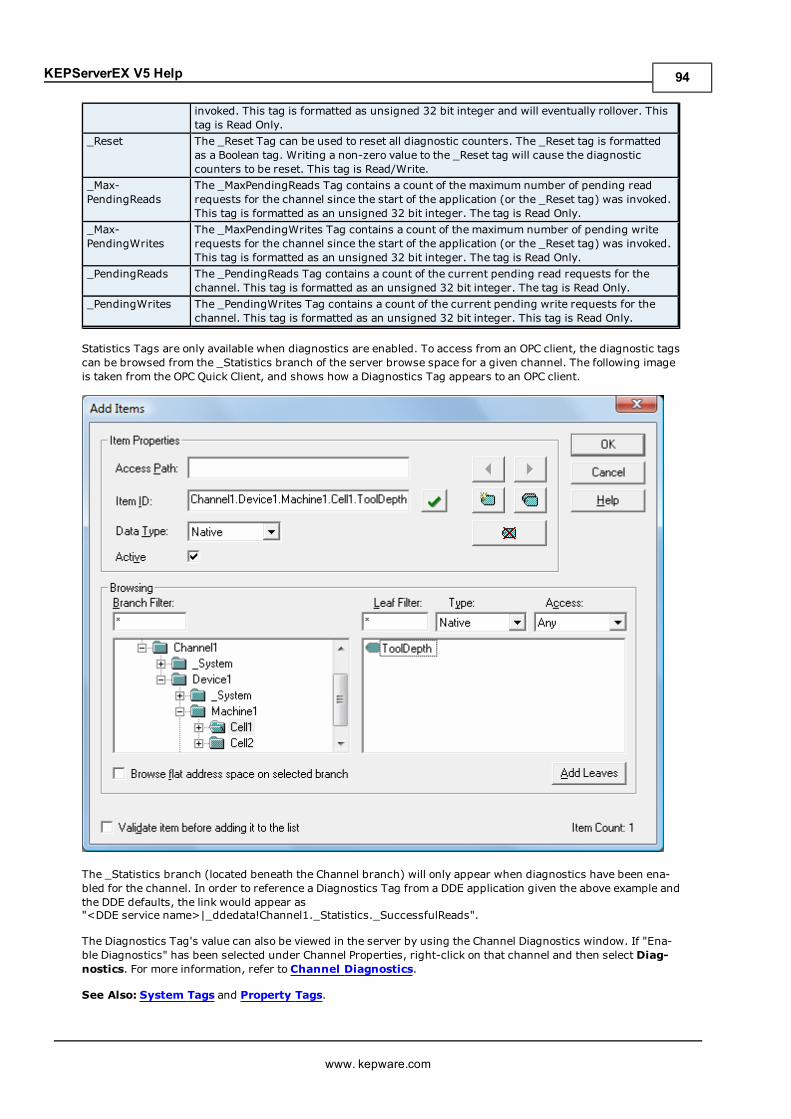
KEPServerEX V5 Help
invoked. This tag is formatted as unsigned 32 bit integer and will eventually rollover. Thistag is Read Only.
_Reset The _Reset Tag can be used to reset all diagnostic counters. The _Reset tag is formattedas a Boolean tag. Writing a non-zero value to the _Reset tag will cause the diagnosticcounters to be reset. This tag is Read/Write.
_Max-PendingReads
The _MaxPendingReads Tag contains a count of the maximum number of pending readrequests for the channel since the start of the application (or the _Reset tag) was invoked.This tag is formatted as an unsigned 32 bit integer. The tag is Read Only.
_Max-PendingWrites
The _MaxPendingWrites Tag contains a count of the maximum number of pending writerequests for the channel since the start of the application (or the _Reset tag) was invoked.This tag is formatted as an unsigned 32 bit integer. The tag is Read Only.
_PendingReads The _PendingReads Tag contains a count of the current pending read requests for thechannel. This tag is formatted as an unsigned 32 bit integer. The tag is Read Only.
_PendingWrites The _PendingWrites Tag contains a count of the current pending write requests for thechannel. This tag is formatted as an unsigned 32 bit integer. This tag is Read Only.
Statistics Tags are only available when diagnostics are enabled. To access from an OPC client, the diagnostic tagscan be browsed from the _Statistics branch of the server browse space for a given channel. The following imageis taken from the OPC Quick Client, and shows how a Diagnostics Tag appears to an OPC client.
The _Statistics branch (located beneath the Channel branch) will only appear when diagnostics have been ena-bled for the channel. In order to reference a Diagnostics Tag from a DDE application given the above example andthe DDE defaults, the link would appear as"<DDE service name>|_ddedata!Channel1._Statistics._SuccessfulReads".
The Diagnostics Tag's value can also be viewed in the server by using the Channel Diagnostics window. If "Ena-ble Diagnostics" has been selected under Channel Properties, right-click on that channel and then select Diag-nostics. For more information, refer to Channel Diagnostics.
See Also: System Tags and Property Tags.
www. kepware.com
94
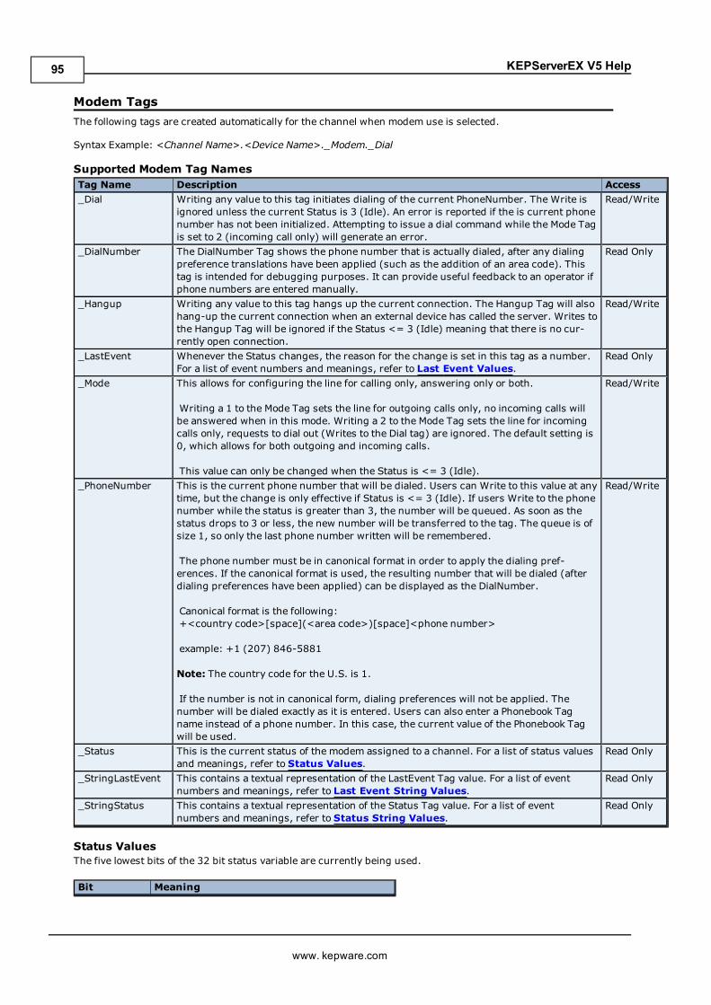
KEPServerEX V5 Help
Modem TagsThe following tags are created automatically for the channel when modem use is selected.
Syntax Example: <Channel Name>.<Device Name>._Modem._Dial
Supported Modem Tag NamesTag Name Description Access_Dial Writing any value to this tag initiates dialing of the current PhoneNumber. The Write is
ignored unless the current Status is 3 (Idle). An error is reported if the is current phonenumber has not been initialized. Attempting to issue a dial command while the Mode Tagis set to 2 (incoming call only) will generate an error.
Read/Write
_DialNumber The DialNumber Tag shows the phone number that is actually dialed, after any dialingpreference translations have been applied (such as the addition of an area code). Thistag is intended for debugging purposes. It can provide useful feedback to an operator ifphone numbers are entered manually.
Read Only
_Hangup Writing any value to this tag hangs up the current connection. The Hangup Tag will alsohang-up the current connection when an external device has called the server. Writes tothe Hangup Tag will be ignored if the Status <= 3 (Idle) meaning that there is no cur-rently open connection.
Read/Write
_LastEvent Whenever the Status changes, the reason for the change is set in this tag as a number.For a list of event numbers and meanings, refer to Last Event Values.
Read Only
_Mode This allows for configuring the line for calling only, answering only or both.
Writing a 1 to the Mode Tag sets the line for outgoing calls only, no incoming calls willbe answered when in this mode. Writing a 2 to the Mode Tag sets the line for incomingcalls only, requests to dial out (Writes to the Dial tag) are ignored. The default setting is0, which allows for both outgoing and incoming calls.
This value can only be changed when the Status is <= 3 (Idle).
Read/Write
_PhoneNumber This is the current phone number that will be dialed. Users can Write to this value at anytime, but the change is only effective if Status is <= 3 (Idle). If users Write to the phonenumber while the status is greater than 3, the number will be queued. As soon as thestatus drops to 3 or less, the new number will be transferred to the tag. The queue is ofsize 1, so only the last phone number written will be remembered.
The phone number must be in canonical format in order to apply the dialing pref-erences. If the canonical format is used, the resulting number that will be dialed (afterdialing preferences have been applied) can be displayed as the DialNumber.
Canonical format is the following:+<country code>[space](<area code>)[space]<phone number>
example: +1 (207) 846-5881
Note: The country code for the U.S. is 1.
If the number is not in canonical form, dialing preferences will not be applied. Thenumber will be dialed exactly as it is entered. Users can also enter a Phonebook Tagname instead of a phone number. In this case, the current value of the Phonebook Tagwill be used.
Read/Write
_Status This is the current status of the modem assigned to a channel. For a list of status valuesand meanings, refer to Status Values.
Read Only
_StringLastEvent This contains a textual representation of the LastEvent Tag value. For a list of eventnumbers and meanings, refer to Last Event String Values.
Read Only
_StringStatus This contains a textual representation of the Status Tag value. For a list of eventnumbers and meanings, refer to Status String Values.
Read Only
Status ValuesThe five lowest bits of the 32 bit status variable are currently being used.
Bit Meaning
www. kepware.com
95
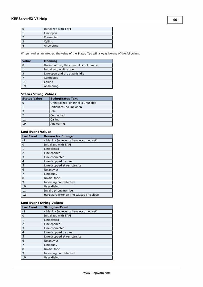
KEPServerEX V5 Help
0 Initialized with TAPI1 Line open2 Connected3 Calling4 Answering
When read as an integer, the value of the Status Tag will always be one of the following:
Value Meaning0 Un-initialized, the channel is not usable1 Initialized, no line open3 Line open and the state is idle7 Connected11 Calling19 Answering
Status String ValuesStatus Value StringStatus Text0 Uninitialized, channel is unusable1 Initialized, no line open3 Idle7 Connected11 Calling19 Answering
Last Event ValuesLastEvent Reason for Change-1 <blank> [no events have occurred yet]0 Initialized with TAPI1 Line closed2 Line opened3 Line connected4 Line dropped by user5 Line dropped at remote site6 No answer7 Line busy8 No dial tone9 Incoming call detected10 User dialed11 Invalid phone number12 Hardware error on line caused line close
Last Event String ValuesLastEvent StringLastEvent-1 <blank> [no events have occurred yet]0 Initialized with TAPI1 Line closed2 Line opened3 Line connected4 Line dropped by user5 Line dropped at remote site6 No answer7 Line busy8 No dial tone9 Incoming call detected10 User dialed
www. kepware.com
96
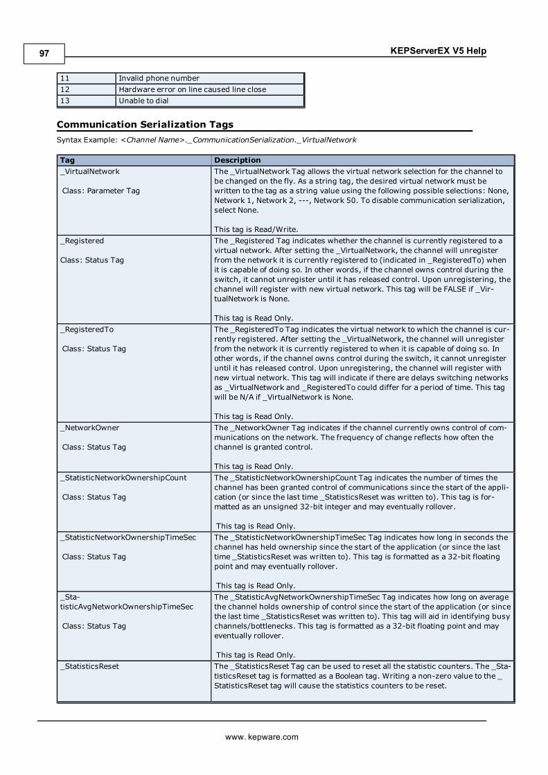
KEPServerEX V5 Help
11 Invalid phone number12 Hardware error on line caused line close13 Unable to dial
Communication Serialization TagsSyntax Example: <Channel Name>._CommunicationSerialization._VirtualNetwork
Tag Description_VirtualNetwork
Class: Parameter Tag
The _VirtualNetwork Tag allows the virtual network selection for the channel tobe changed on the fly. As a string tag, the desired virtual network must bewritten to the tag as a string value using the following possible selections: None,Network 1, Network 2, ---, Network 50. To disable communication serialization,select None.
This tag is Read/Write._Registered
Class: Status Tag
The _Registered Tag indicates whether the channel is currently registered to avirtual network. After setting the _VirtualNetwork, the channel will unregisterfrom the network it is currently registered to (indicated in _RegisteredTo) whenit is capable of doing so. In other words, if the channel owns control during theswitch, it cannot unregister until it has released control. Upon unregistering, thechannel will register with new virtual network. This tag will be FALSE if _Vir-tualNetwork is None.
This tag is Read Only._RegisteredTo
Class: Status Tag
The _RegisteredTo Tag indicates the virtual network to which the channel is cur-rently registered. After setting the _VirtualNetwork, the channel will unregisterfrom the network it is currently registered to when it is capable of doing so. Inother words, if the channel owns control during the switch, it cannot unregisteruntil it has released control. Upon unregistering, the channel will register withnew virtual network. This tag will indicate if there are delays switching networksas _VirtualNetwork and _RegisteredTo could differ for a period of time. This tagwill be N/A if _VirtualNetwork is None.
This tag is Read Only._NetworkOwner
Class: Status Tag
The _NetworkOwner Tag indicates if the channel currently owns control of com-munications on the network. The frequency of change reflects how often thechannel is granted control.
This tag is Read Only._StatisticNetworkOwnershipCount
Class: Status Tag
The _StatisticNetworkOwnershipCount Tag indicates the number of times thechannel has been granted control of communications since the start of the appli-cation (or since the last time _StatisticsReset was written to). This tag is for-matted as an unsigned 32-bit integer and may eventually rollover.
This tag is Read Only._StatisticNetworkOwnershipTimeSec
Class: Status Tag
The _StatisticNetworkOwnershipTimeSec Tag indicates how long in seconds thechannel has held ownership since the start of the application (or since the lasttime _StatisticsReset was written to). This tag is formatted as a 32-bit floatingpoint and may eventually rollover.
This tag is Read Only._Sta-tisticAvgNetworkOwnershipTimeSec
Class: Status Tag
The _StatisticAvgNetworkOwnershipTimeSec Tag indicates how long on averagethe channel holds ownership of control since the start of the application (or sincethe last time _StatisticsReset was written to). This tag will aid in identifying busychannels/bottlenecks. This tag is formatted as a 32-bit floating point and mayeventually rollover.
This tag is Read Only._StatisticsReset The _StatisticsReset Tag can be used to reset all the statistic counters. The _Sta-
tisticsReset tag is formatted as a Boolean tag. Writing a non-zero value to the _StatisticsReset tag will cause the statistics counters to be reset.
www. kepware.com
97

KEPServerEX V5 Help
This tag is Read/Write.
www. kepware.com
98
KEPServerEX V5 Help
Communications ManagementAuto-DemotionThe Auto-Demotion parameters allow a driver to temporarily place a device off-scan in the event that a device isnot responding. By placing a nonresponsive device offline, the driver can continue to optimize its com-munications with other devices on the same channel by stopping communications with the nonresponsive devicefor a specific time period. After the specific time period has been reached, the driver will re-attempt to com-municate with the nonresponsive device. If the device is responsive, the device will be placed on-scan; other-wise, it will restart its off-scan time period. For more information, refer toDevice Properties - Auto-Demotion.
Network Interface SelectionAn NIC card can be selected for use with any Ethernet driver or serial driver running in Ethernet Encapsulationmode. The Network Interface feature is used to select a specific NIC card based on either the NIC name or its cur-rently assigned IP address. The list of available NICs will include both unique NIC cards and NICs that have mul-tiple IPs assigned to them. The selection will also display any WAN connections that may be active (such as adialup connection).
Ethernet EncapsulationThe Ethernet Encapsulation mode has been designed to provide communications with serial devices connected toterminal servers on the Ethernet network. A terminal server is essentially a virtual serial port: the terminal serverconverts TCP/IP messages on the Ethernet network to serial data. Once the message has been converted to aserial form, users can connect standard devices that support serial communications to the terminal server. Usinga terminal server device allows users to place RS-232 and RS-485 devices throughout the plant operations whilestill allowing a single localized PC to access the remotely mounted devices. Furthermore, the Ethernet Encap-sulation mode allows an individual Network IP address to be assigned to each device as needed. By using multipleterminal servers, users can access hundreds of serial devices from a single PC via the Ethernet network. Formore information, refer toHow Do I... and Device Properties - Ethernet Encapsulation.
Modem SupportThis server supports the use of modems to connect to remote devices, which is established through the use ofspecial modem tags that become available at the channel-level when a dial-up network connection has beencreated. These channel-level modem tags can be used to dial a remote device, monitor the modem status whileconnected and terminate the call when completed.
Note: Not all serial drivers support the use of modems. To determine modem support, refer to the specific driv-er's help documentation.
When accessing the new modem tags, the channel name can be used as either a base group or topic name. If theproject contains more than one channel definition, users will need to configure the channel names so that each isunique. This remains true for device names, as well. Channel names can no longer match the device name whenthe project needs to be configured to use a modem. The channel name requirements do not apply to projects thatare not using a modem.
In order to be used, modems need to be configured with the operating system through the Control Panel settings.For specific setup information, refer to the Windows and modem documentation. Once the modem has been prop-erly installed, it can be enabled by selecting the Use Modem checkbox in the Channel Wizard.
Important: Many new commercial modems are designed to dial-up network server connections and negotiatethe fastest and clearest signal. When communicating to a serial automation device, the modem needs to connectat a specific Baud (Bits per Second) and Parity. For this reason, an external modem (which can be configured todial using specific Baud Rate and Parity settings) is strongly recommended. To determine the best modem for aspecific application, refer to Technical Support. For examples on how to use a modem in a project, refer toUsinga Modem in the Server Project.
Using a Modem in the Server ProjectModems convert serial data from the RS-232 port into signal levels that can be transmitted over the phone line.To do this, they break down each byte of the serial data into bits that are then used to generate the signal that willbe transmitted. Most modems can convert up to 10 bits of information for every byte of data that is sent. Devicesmust be able to use 10 bits or less in order to communicate through a modem. To determine the amount of bitsbeing used by a specific device, refer to the formula below.
Start Bits + Data Bits + Parity + Stop Bits = Total Bit Count
www. kepware.com
99
KEPServerEX V5 Help
For example, the Modbus RTU Driver is configured to use 8 Data Bits, Even Parity, 1 Stop Bit, and 1 Start Bit.When plugged into the formula, it would be 1 + 8 + 1 + 1, which equals 11 bits. A normal modem could not trans-mit data to this Modbus device. If Parity is changed to None, it would be 1 + 8 + 0 + 1, which equals 10 Bits. Anormal modem could transmit data to this Modbus device.
Some drivers cannot be configured to use a 10 bit or less data format, and so cannot use standard modems.Instead, they require modems that can handle transmitting 11 data bits. For drivers that fall into this category,consult the device's manufacturer for recommendations on an appropriate modem vendor. Modem operation isenabled for all serial drivers regardless of their suitability for modem operation.
Configuring the Initiating ModemThis server uses the Windows TAPI interface to access modems attached to the PC. The TAPI interface wasdesigned to provide Windows programs a common interface that could be accessed by a range of modems exist-ing in a PC. A set of drivers provided by the modem's manufacturer for the Windows OS must be installed beforethe server can use the modem in a project. The Windows Control Panel can be used to install new modems. Forinformation regarding modem installation and setup, refer to both the Windows and the modem's help doc-umentation.
Once the modem has been properly installed, users can begin using it in a server project. The receiving end, orthe device modem, must be properly configured before it can be used. Users will need to confirm that the receiv-ing modemmatches the profile provided by the driver.
Configuring the Receiving ModemTo easily configure the receiving modem, use the Hyperterminal program that is included with Windows. Formore information, follow the instructions below.
Note: The following example uses a project that specified the connection to use 10 bits or less.
1. To start, use an available Serial Port to connect the desired receiving modem to the PC.
2. Next, start Hyperterminal and open a new connection. Name this new connection "ModemSetup".
3. In Connect To, click the Connect Using drop-down menu and then select the communication port towhich the receiving modem is attached. Other modems may appear in this list.
4. In COMx Properties, configure the communications port settings that will be used to talk to the receivingmodem.
Important: The COMx Properties settings must match the Baud Rate, Data Bits, Parity, and Stop Bitsused by the target device. Modems remember the settings that were used to talk to it last; thus, if thereceiving modem was configured at 19,200 baud but the device was configured for 9600 baud, themodem will never be able to speak to the device. Although it could connect, the receiving modem wouldsend all the data to the device at 19,200 baud. This is true even if the modem connects at 9600 baud or ifthe transmitting modem is being spoken to at 9600 baud. Any disparity between the settings will causethe modem application to fail. To avoid the error, match the settings between the newly created serverproject and one that has a direct cable connection.
5. Next, enter the port settings. Once finished, click OK.
Note: At this point, users should be able to issue commands to the receiving modem. On many modems,this can be tested by typing "ATI4" followed by "Enter". If the modem is properly attached to the PC, it willrespond by displaying its current profile settings. For information on a specific modem, refer to its helpdocumentation.
6. Set the receiving modem's desired profile and then save the settings by issuing a write command. To doso, type "AT&W0" followed by "Enter".
Note: To test the receiving modem's configuration, simply turn it off for a moment and then turn it backon.
7. Next, type "AT14" followed by "Enter" (or another applicable command). The modem should display itscurrent profile, including any changes that have been made.
Important: The profile settings and reference documents are provided as examples. Due to the dif-ferences in configuration commands and codes among modemmanufacturers, users should refer to themodem's help documentation.
Cables
www. kepware.com
100
KEPServerEX V5 Help
Before the project can be used, the cable connection must be configured between the receiving modem and thedevice. Three cables are required: the existing device communication cable for direct connection, a NULL modemadapter, and a NULL modem cable. A NULL modem cable is connected to the modem, and all pins are connectedto the same pins on both ends of the cable. The device communication cable is used to connect to the targetdevice, and usually has pins 2 and 3 reversed. Because the cable being used to talk to the device for the directconnection is working by this point, it can be used on the receiving modem by attaching a NULL modem adapter.Similarly, a PCmodem cable will run from the PC to the initiating modem. With the cables in place, a modem cannow be used in the application.
Note: NULL modem adapters can be found at most computer stores.
Example: Server Side Modem ConfigurationAfter the modems have been configured and installed, they can be used with the server.
1. To start, load the direct connect project and then double-click on the channel name. In Channel Prop-erties selectModem from the Connection Type drop-down menu.
2. Next, open theModem tab to display the list of modems that are available on the computer.
Note: If no modems are listed, exit the server and attempt to reinstall the modem using the Modem Con-figuration tools supplied by the operating system.
3. Select the modem that will be used with the server project. Then, click Properties to configure the ini-tiating modem's characteristics. Descriptions of the tabs are as follows:
l General: This tab is used to specify call and data connection preferences.
l Advanced: This tab is used to specify terminal window and hardware settings.
Note: For more information about recommended settings, refer to the specific driver's help doc-umentation.
4. Once finished, clickOK. Then, clickOK again to save and exit the Channel Properties.
Using a Modem in Your ApplicationOnce modem operation has been enabled, a list of pre-defined tags will be made available in the driver's Tag Win-dow. These Modem Tags control and monitor an attached modem, and are contained under the channel name(which has become an active OPC Access path through which the Modem Tags are accessed). Because the serverknows very little about what the application needs for modem control, it does not imply any type of control. Byusing the predefined Modem Tags, users can apply the application's scripting capabilities to control how theserver uses the selected modem.
Phonebook TagsA Phonebook Tag can be used in place of specifying a telephone number by directly writing to the Phone NumberTag. A Phonebook Tag can be created on the channel, along with the other modem system tags previouslydescribed. The data associated with a Phonebook Tag is a phone number that can be assigned when the tag iscreated and/or later modified when the server has an active client connection. The phone number stored in aphonebook tag can be used to dial by simply writing anything to the tag. The act of writing will cause the selectedPhonebook Tag to dial.
Syntax Example: <Channel Name>._Phonebook.<Phonebook Tag Name>
Data Type PrivilegeString Read/Write
Phonebook Tags are entered using the dialog shown below. To add a new Phonebook Tag, click on the New Phone-book icon to display the Phone Number Tags dialog.
www. kepware.com
101
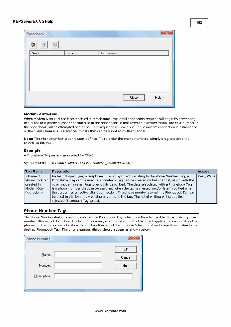
KEPServerEX V5 Help
Modem Auto-DialWhen Modem Auto-Dial has been enabled in the channel, the initial connection request will begin by attemptingto dial the first phone number encountered in the phonebook. If that attempt is unsuccessful, the next number inthe phonebook will be attempted and so on. This sequence will continue until a modem connection is establishedor the client releases all references to data that can be supplied by the channel.
Note: The phone number order is user-defined. To re-order the phone numbers, simply drag and drop theentries as desired.
ExampleA Phonebook Tag name was created for 'Site1.'
Syntax Example: <Channel Name>.<Device Name>._Phonebook.Site1
Tag Name Description Access<Name ofPhone book tagcreated inModem Con-figuration>
Instead of specifying a telephone number by directly writing to the Phone Number Tag, aPhonebook Tag can be used. A Phonebook Tag can be created on the channel, along with theother modem system tags previously described. The data associated with a Phonebook Tagis a phone number that can be assigned when the tag is created and/or later modified whenthe server has an active client connection. The phone number stored in a Phonebook Tag canbe used to dial by simply writing anything to the tag. The act of writing will cause theselected Phonebook Tag to dial.
Read/Write
Phone Number TagsThe Phone Number dialog is used to enter a new Phonebook Tag, which can then be used to dial a desired phonenumber. Phonebook Tags keep the list in the server, which is useful if the OPC client application cannot store thephone number for a device location. To invoke a Phonebook Tag, the OPC client must write any string value to thedesired Phonebook Tag. The phone number dialog should appear as shown below.
www. kepware.com
102
KEPServerEX V5 Help
Descriptions of the parameters are as follows:
l Name: This parameter is used to enter the string that will represent the phone number available from thePhonebook Tag. Names can be up to 256 characters in length. Although using descriptive names is gen-erally a good idea, some OPC client applications may have a limited display window when browsing the tagspace of an OPC server. The Phonebook Tag name is part of the OPC browse data. Phonebook Tag namesmust be unique within a given device. For information on reserved characters, refer toHow To... Prop-erly Name a Channel, Device, Tag, and Tag Group.
l Number: This parameter is used to enter the phone number that will be dialed when the tag is invokedfrom an OPC client application. A string of up to 64 digits can be entered.
l Description: This parameter is used to attach a comment to this tag. A string of up to 64 characters canbe entered.
Note:With the server's online full-time operation, these parameters can be changed at any time. Changes madeto Tag Properties will take effect immediately; however, OPC clients that have already connected to this tag willnot be affected until they release and reacquire this tag. To prevent operators from changing these parametersuse the User Manager to restrict access rights to server features.
Modem Auto-DialModem Auto-Dial (MAD) automates the actions required of a client application when modem use is specifiedwithin the server project. These actions (which include phone number assignment, connecting, and dis-connecting) must be performed by an external client application through the use of channel-level Modem Tags.For example, in order to begin the process of establishing a connection, the client must write a dial string to"<channel>._Modem._PhoneNumber" and then write a value to "<channel>._Modem._Dial". When data fromthe remote device is no longer needed, the client must end the call by writing to "<channel>._Modem._Hangup".
Modem Auto-Dial relieves the client of these responsibilities by automatically dialing phone numbers defined inthe Phonebook when attempting to establish a connection. The connection will be automatically dropped whenthere are no client references to tags that rely on the modem connection. To access the Modem Auto-Dial set-tings, click Channel Properties | Modem. For more information, refer to Channel Properties - Modem.
Modem Connection and DisconnectionThe process of establishing a modem connection will begin when a client connects to the server Runtime andrequests data from a device connection to a channel on which Modem Auto-Dial is enabled. The initial connectionrequest will begin by attempting to dial the first phone number encountered in the phonebook. If that attempt isunsuccessful, the next number in the phonebook will be attempted and so on. This sequence will continue until amodem connection is established or the client releases all references to data that can be supplied by the channel.
Note:When re-establishing a connection, the phonebook entry that last produced a successful connection willbe used. If no previous phonebook entry was successful (or if the entry has since been deleted), the user-defined sequence of phone numbers will be used. The number used for re-dialing will not be preserved duringserver re-initialization or restart.
See Also: Phonebook Tags
TimingTiming settings (such as how long to wait for a connection before proceeding to the next phone number) aredetermined by the TAPI modem configuration and not by any specific Modem Auto-Dial setting.
Note: Some drivers do not allow the serial port to close once it has opened. Connections established using thesedrivers will not experience disconnection until all client references have been released (that is, unless the TAPIsettings are configured to disconnect after a period of idle time).
Client AccessModem Tags may still be used to exert client-level control over the modem. If Modem Auto-Dialing is enabled, how-ever, Write access to the Modem Tags will be restricted so that only one form of access is possible. The ModemTags' values will be updated just as they would if the client were in control of the modem.
Changing the Modem Auto-Dial Settings from the ConfigurationThe Runtime will react to settings changes according to the following rules:
l If MAD is enabled after the client has already dialed the modem and established a connection, the changewill be ignored until the modem is disconnected. If the client is still requesting data from the channel atthe time of disconnection, the initial connection sequence will begin.
www. kepware.com
103

KEPServerEX V5 Help
l If MAD is enabled while no modem connection exists and data is being requested from the channel by theclient, the initial connection sequence will begin.
l If MAD is disabled while an existing auto-dial connection exists, no action will be taken and the connectionwill be dropped.
l If all entries are deleted from the phonebook, MAD will be disabled.
See Also: Channel Properties - Modem
www. kepware.com
104
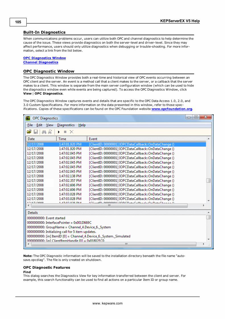
KEPServerEX V5 Help
Built-In DiagnosticsWhen communications problems occur, users can utilize both OPC and channel diagnostics to help determine thecause of the issue. These views provide diagnostics on both the server-level and driver-level. Since they mayaffect performance, users should only utilize diagnostics when debugging or trouble-shooting. For more infor-mation, select a link from the list below.
OPC Diagnostics WindowChannel Diagnostics
OPC Diagnostic WindowThe OPC Diagnostics Window provides both a real-time and historical view of OPC events occurring between anOPC client and the server. An event is a method call that a client makes to the server, or a callback that the servermakes to a client. This window is separate from the main server configuration window (which can be used to hidethe diagnostics window even while events are being captured). To access the OPC Diagnostics Window, clickView | OPC Diagnostics.
The OPC Diagnostics Window captures events and details that are specific to the OPC Data Access 1.0, 2.0, and3.0 Custom Specifications. For more information on the data presented in this window, refer to those spec-ifications. Copies of these specifications can be found on the OPC Foundation websitewww.opcfoundation.org.
Note: The OPC Diagnostic information will be saved to the installation directory beneath the file name "auto-save.opcdiag". The file is only created on shutdown.
OPC Diagnostic FeaturesFindThis dialog searches the Diagnostics View for key information transferred between the client and server. Forexample, this search functionality can be used to find all actions on a particular Item ID or group name.
www. kepware.com
105
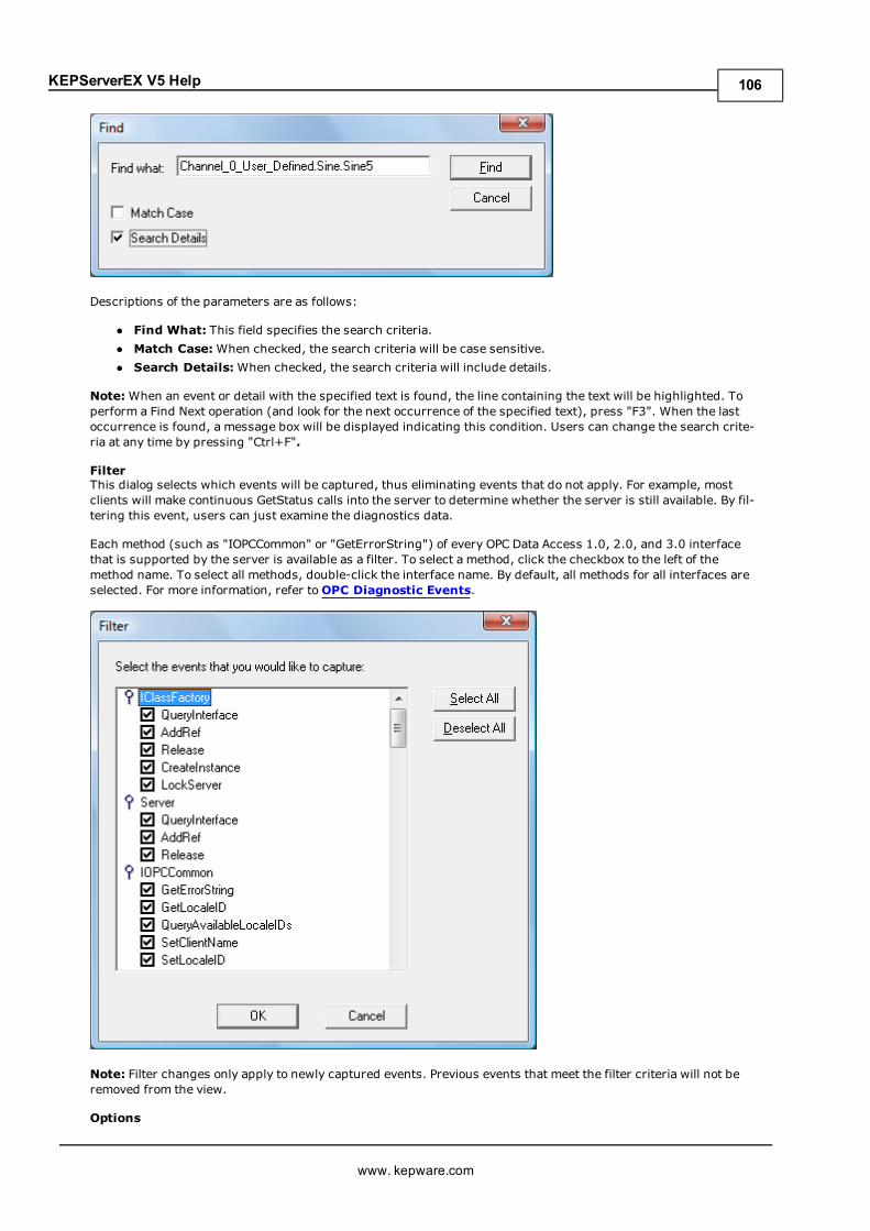
KEPServerEX V5 Help
Descriptions of the parameters are as follows:
l Find What: This field specifies the search criteria.l Match Case:When checked, the search criteria will be case sensitive.l Search Details:When checked, the search criteria will include details.
Note:When an event or detail with the specified text is found, the line containing the text will be highlighted. Toperform a Find Next operation (and look for the next occurrence of the specified text), press "F3". When the lastoccurrence is found, a message box will be displayed indicating this condition. Users can change the search crite-ria at any time by pressing "Ctrl+F".
FilterThis dialog selects which events will be captured, thus eliminating events that do not apply. For example, mostclients will make continuous GetStatus calls into the server to determine whether the server is still available. By fil-tering this event, users can just examine the diagnostics data.
Each method (such as "IOPCCommon" or "GetErrorString") of every OPC Data Access 1.0, 2.0, and 3.0 interfacethat is supported by the server is available as a filter. To select a method, click the checkbox to the left of themethod name. To select all methods, double-click the interface name. By default, all methods for all interfaces areselected. For more information, refer toOPC Diagnostic Events.
Note: Filter changes only apply to newly captured events. Previous events that meet the filter criteria will not beremoved from the view.
Options
www. kepware.com
106
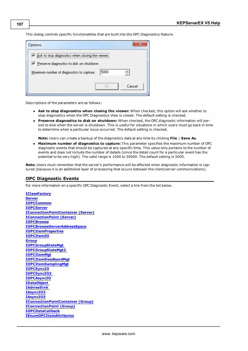
KEPServerEX V5 Help
This dialog controls specific functionalities that are built into the OPC Diagnostics feature.
Descriptions of the parameters are as follows:
l Ask to stop diagnostics when closing the viewer:When checked, this option will ask whether tostop diagnostics when the OPC Diagnostics View is closed. The default setting is checked.
l Preserve diagnostics to disk on shutdown:When checked, the OPC diagnostic information will per-sist to disk when the server is shutdown. This is useful for situations in which users must go back in timeto determine when a particular issue occurred. The default setting is checked.
Note: Users can create a backup of the diagnostics data at any time by clicking File | Save As.l Maximum number of diagnostics to capture: This parameter specifies the maximum number of OPCdiagnostic events that should be captured at any specific time. This value only pertains to the number ofevents and does not include the number of details (since the detail count for a particular event has thepotential to be very high). The valid range is 1000 to 30000. The default setting is 5000.
Note: Users must remember that the server's performance will be affected when diagnostic information is cap-tured (because it is an additional layer of processing that occurs between the client/server communications).
OPC Diagnostic EventsFor more information on a specific OPC Diagnostic Event, select a link from the list below.
IClassFactoryServerIOPCCommonIOPCServerIConnectionPointContainer (Server)IConnectionPoint (Server)IOPCBrowseIOPCBrowseServerAddressSpaceIOPCItemPropertiesIOPCItemIOGroupIOPCGroupStateMgtIOPCGroupStateMgt2IOPCItemMgtIOPCItemDeadbandMgtIOPCItemSamplingMgtIOPCSyncIOIOPCSyncIO2IOPCAsyncIOIDataObjectIAdviseSinkIAsyncIO2IAsyncIO3IConnectionPointContainer (Group)IConnectionPoint (Group)IOPCDataCallbackIEnumOPCItemAttributes
www. kepware.com
107
KEPServerEX V5 Help
IClassFactoryThe IClassFactory interface contains several methods intended to deal with an entire class of objects. It is imple-mented on the class object for a specific class of objects and is identified by a CLSID.
l QueryInterface: The client can ask the object whether it supports any outgoing interfaces by callingQueryInterface for IConnectionPointContainer. If the object answers "yes" by handing back a validpointer, the client knows it can attempt to establish a connection.
l AddRef: Increments the reference count for an interface on an object. It should be called for every newcopy of a pointer to an interface on a given object.
l Release: Decreases the reference count of the interface by 1.l CreateInstance: Creates an uninitialized object.l LockServer: Allows instances to be created quickly when called by the client of a class object to keep aserver open in memory.
ServerThe client calls CoCreateInstance to create the server object and the initial interface.
l QueryInterface: The client can ask the object whether it supports any outgoing interfaces by callingQueryInterface for IConnectionPointContainer. If the object answers "yes" by handing back a validpointer, the client knows it can attempt to establish a connection.
l AddRef: Increments the reference count for an interface on an object. It should be called for every newcopy of a pointer to an interface on a given object.
l Release: Decreases the reference count of the interface by 1.
IOPCCommonThis interface is used by all OPC Server types (DataAccess, Alarm&Event, Historical Data and so forth). It pro-vides the ability to set and query a Locale ID which would be in effect for the particular client/server session. Theactions of one client will not affect other clients.
l GetErrorString: Returns the error string for a server specific error code. The expected behavior is thatthis will include handling of Win32 errors as well (such as RPC errors).
l GetLocaleID: Returns the default Locale ID for this server/client session.l QueryAvailableLocaleIDs: Returns the available Locale IDs for this server/client session.l SetClientName: Allows the client to optionally register a client name with the server. This is included pri-marily for debugging purposes. The recommended behavior is that users set the Node name and EXEname here.
l SetLocaleID: Sets the default Locale ID for this server/client session. This Locale ID will be used by theGetErrorString method on this interface. The default value for the server should be LOCALE_SYSTEM_DEFAULT.
IOPCServerThis is an OPC server's main interface. The OPC server is registered with the operating system as specified in theInstallation and Registration Chapter of this specification.
l AddGroup: Adds a Group to a Server. A Group is a logical container for a client to organize and manip-ulate data items.
l CreateGroupEnumerator: Creates various enumerators for the groups provided by the Server.l GetErrorString: Returns the error string for a server specific error code.l GetGroupByName: Returns an additional interface pointer when given the name of a private group(created earlier by the same client). Use GetPublicGroupByName to attach to public groups. This functioncan be used to reconnect to a private group for which all interface pointers have been released.
l GetStatus: Returns current status information for the server.l RemoveGroup: Deletes the Group. A group is not deleted when all the client interfaces are released,since the server itself maintains a reference to the group. The client may still call GetGroupByName afterall the interfaces have been released. RemoveGroup() causes the server to release it's 'last' reference tothe group, which results in the group being deleted.
IConnectionPointContainer (Server)This interface provides the access to the connection point for IOPCShutdown.
www. kepware.com
108
KEPServerEX V5 Help
l EnumConnectionPoints: Creates an enumerator for the connection points supported between the OPCGroup and the Client. OPCServers must return an enumerator that includes IOPCShutdown. Additional ven-dor specific callbacks are allowed.
l FindConnectionPoint: Finds a particular connection point between the OPC Server and the Client.OPCServers must support IID_IOPCShutdown. Additional vendor specific callbacks are allowed.
IConnectionPoint (Server)This interface establishes a call back to the client.
l Advise: Establishes an advisory connection between the connection point and the caller's sink object.l EnumConnections: Creates an enumerator object for iteration through the connections that exist to thisconnection point.
l GetConnectionInterface: Returns the IID of the outgoing interface managed by this connection point.l GetConnectionPointContainer: Retrieves the IConnectionPointContainer interface pointer to the con-nectable object that conceptually owns the connection point.
l Unadvise: Terminates an advisory connection previously established through the Advise method.l ShutdownRequest: Allows the server to request that all clients disconnect from the server.
IOPCBrowseIOPCBrowse interface provides improved methods for browsing the server address space and for obtaining theitem properties.
l GetProperties: Returns an array of OPCITEMPROPERTIES, one for each Item ID.l Browse: Browses a single branch of the address space and returns zero or more OPCBROWSEELEMENTstructures.
IOPCBrowseServerAddressSpaceThis interface provides a way for clients to browse the available data items in the server, giving the user a list ofthe valid definitions for an Item ID. It allows for either flat or hierarchical address spaces and is designed to workwell over a network. It also insulates the client from the syntax of a server vendor specific Item ID.
l BrowseAccessPaths: Provides a way to browse the available AccessPaths for an Item ID.l BrowseOPCItemIDs: Returns an IENUMString for a list of Item IDs as determined by the passed param-eters. The position from which the browse is made can be set in ChangeBrowsePosition.
l ChangeBrowserPosition: Provides a way to move up, down or to in a hierarchical space.l GetItemID: Provides a way to assemble a fully qualified Item ID in a hierarchical space. This is requiredsince the browsing functions return only the components or tokens that make up an Item ID and do notreturn the delimiters used to separate those tokens. Also, at each point one is browsing just the namesbelow the current node (e.g. the units in a cell).
l QueryOrganization: Provides a way to determine if the underlying system is inherently flat or hier-archical and how the server may represent the information of the address space to the client. Flat and hier-archical spaces behave somewhat different. If the result is flat then the client knows that there is no needto pass the Branch or Leaf flags to BrowseOPCItem IDs or to call ChangeBrowsePosition.
IOPCItemPropertiesThis interface can be used to browse the available properties associated with an Item ID as well as to Read theproperties' current values.
l GetItemProperties: Returns a list of the current data values for the passed ID codes.l LookUpItemIDs: Returns a list of Item IDs for each of the passed ID codes if any are available. Theseindicate the Item ID which could be added to an OPCGroup and used for more efficient access to the datacorresponding to the Item Properties.
l QueryAvailableProperties: Returns a list of ID codes and descriptions for the available properties forthis Item ID. This list may differ for different Item IDs. This list is expected to be relatively stable for a par-ticular Item ID, although it could be affected from time to time by changes to the underlying system's con-figuration. The Item ID is passed to this function because servers are allowed to return different sets ofproperties for different Item IDs.
IOPCItemIOThe purpose of this interface is to provide an extremely easy way for simple applications to obtain OPC data.
www. kepware.com
109
KEPServerEX V5 Help
l Read: Reads one or more values, qualities and timestamps for the items specified. This is functionally sim-ilar to the IOPCSyncIO::Read method.
l WriteVQT:Writes one or more values, qualities and timestamps for the items specified. This is func-tionally similar to the IOPCSyncIO2::WriteVQT except that there is no associated group. If a clientattempts to write VQ, VT, or VQT it should expect that the server will Write them all or none at all.
GroupThe client calls CoCreateInstance to create the Server object and the initial interface.
l QueryInterface: The client can ask the object whether it supports any outgoing interfaces by callingQueryInterface for IConnectionPointContainer. If the object answers "yes" by handing back a validpointer, the client knows it can attempt to establish a connection.
l AddRef: Increments the reference count for an interface on an object. It should be called for every newcopy of a pointer to an interface on a given object.
l Release: Decreases the reference count of the interface by 1.
IOPCGroupStateMgtIOPCGroupStateMgt allows the client to manage the overall state of the group. Primarily, this accounts forchanges made to the group's update rate and active state.
l CloneGroup: Creates a second copy of a group with a unique name.l GetState: Gets the current state of the group. This function is typically called to obtain the currentvalues of this information prior to calling SetState. This information was all supplied by or returned to theclient when the group was created.
l SetName: Changes the name of a private group. The namemust be unique. The name cannot bechanged for public groups. Group names are required to be unique with respect to an individual client toserver connection.
l SetState: Sets various properties of the group. This represents a new group which is independent of theoriginal group.
IOPCGroupStateMgt2This interface was added to enhance the existing IOPCGroupStateMgt interface.
l SetKeepAlive: Causes the server to provide client callbacks on the subscription when there are no newevents to report. Clients can then be assured of the health of the server and subscription without resort-ing to pinging the server with calls to GetStatus().
l GetKeepAlive: Returns the currently active keep-alive time for the subscription.
IOPCItemMgtThis interface allows a client to add, remove and control the behavior of items is a group.
l AddItems: Adds one or more items to a group. It is acceptable to add the same item to the group morethan once, thus generating a second item with a unique ServerHandle.
l CreateEnumerator: Creates an enumerator for the items in the group.l RemoveItems: Removes items from a group. Removing items from a group does not affect the addressspace of the server or physical Device. It simply indicates whether or not the client is interested in thoseparticular items.
l SetActiveState: Sets one or more items in a group to active or inactive. This controls whether or notvalid data can be obtained from Read cache for those items and whether or not they are included in theIAdvise subscription to the group. Deactivating items will not result in a callback, since by definition call-backs do not occur for inactive items. Activating items will generally result in an IAdvise callback at thenext UpdateRate period.
l SetClientHandles: Changes the client handle for one or more items in a group. In general, it is expectedthat clients will set the client handle when the item is added and not change it later.
l SetDataTypes: Changes the requested data type for one or more items in a group. In general, it isexpected that clients will set the requested datatype when the item is added and not change it later.
l ValidateItems: Determines if an item is valid and could be added without error. It also returns infor-mation about the item such as canonical datatype. It does not affect the group in any way.
IOPCItemDeadbandMgtForce a callback to IOPCDataCallback::OnDataChange for all active items in the group, whether they havechanged or not. Inactive items are not included in the callback. The MaxAge value will determine where the data
www. kepware.com
110
KEPServerEX V5 Help
is obtained. There will be only one MaxAge value, which will determine the MaxAge for all active items in thegroup. This means some of the values may be obtained from cache while others could be obtained from theDevice depending on the "freshness" of the data in the cache.
l SetItemDeadband: Overrides the deadband specified for the group for each item.l GetItemDeadband: Gets the deadband values for each of the requested items.l ClearItemDeadband: Clears the individual item PercentDeadband, effectively reverting them back to thedeadband value set in the group.
IOPCItemSamplingMgtThis optional interface allows the client to manipulate the rate at which individual items within a group areobtained from the underlying Device. It does not affect the group update rate of the callbacks for OnDataChange.
l SetItemSamplingRate: Sets the sampling rate on individual items. This overrides the update rate of thegroup as far as collection from the underlying Device is concerned. The update rate associated withindividual items does not affect the callback period.
l GetItemSamplingRate: Gets the sampling rate on individual items, which was previously set with SetI-temSamplingRate.
l ClearItemSamplngRate: Clears the sampling rate on individual items, which was previously set withSetItemSamplingRate. The item will revert back to the update rate of the group.
l SetItemBufferEnable: Requests that the server turns on or off, depending on the value of the bEnableparameter, the buffering of data for the identified items, which are collected for items that have an updaterate faster than the group update rate.
l GetItemBufferEnable: Queries the current state of the servers buffering for requested items.
IOPCSyncIOIOPCSyncIO allows a client to perform synchronous Read and Write operations to a server. The operations will runto completion.
l Read: Reads the value, quality and timestamp information for one or more items in a group. The functionruns to completion before returning. The data can be read from cache in which case it should be accurateto within the 'UpdateRate' and percent deadband of the group. The data can be read from the Device, inwhich case an actual Read of the physical Device must be performed. The exact implementation of cacheand Device Reads is not defined by the specification.
l Write:Writes values to one or more items in a group. The function runs to completion. The values arewritten to the Device, meaning that the function should not return until it verifies that the Device has actu-ally accepted or rejected the data. Writes are not affected by the active state of the group or item.
IOPCSyncIO2This interface was added to enhance the existing IOPCSyncIO interface.
l ReadMaxAge: Reads one or more values, qualities and timestamps for the items specified. This is func-tionally similar to the OPCSyncIO::Read method except no source is specified (Device or cache). Theserver will make the determination as whether the information will be obtained from the Device or cache.This decision will be based upon the MaxAge parameter. If the information in the cache is within the Max-Age, then the data will be obtained from the cache, otherwise the server must access the Device for therequested information.
l WriteVQT:Writes one or more values, qualities and timestamps for the items specified. This is func-tionally similar to the IOPCSyncIO::Write except that Quality and Timestamp may be written. If a clientattempts to write VQ, VT or VQT it should expect that the server will Write to all or none.
IOPCAsyncIOIOPCAsyncIO allows a client to perform asynchronous Read and Write operations to a server. The operations willbe 'queued' and the function will return immediately so that the client can continue to run. Each operation istreated as a 'transaction' and is associated with a Transaction ID. As the operations are completed, a callback willbe made to the IAdvise Sink in the client (if one has been established). The information in the callback will indi-cate the Transaction ID and the error results. By convention, 0 is an invalid Transaction ID.
l Cancel: Requests that the server cancel an outstanding transaction.l Read: Reads one or more items in a group. The results are returned via the IAdvise Sink connection estab-lished through the IDataObject. For cache Reads the data is only valid if both the group and the item areactive. Device Reads are not affected by the active state of the group or item.
www. kepware.com
111
KEPServerEX V5 Help
l Refresh: Forces a callback for all active items in the group, whether they have changed or not. Inactiveitems are not included in the callback.
l Write:Writes one or more items in a group. The results are returned via the IAdviseSink connectionestablished through the IDataObject.
IDataObjectIDataObject is implemented on the OPCGroup rather than on the individual items. This allows the creation of anAdvise connection between the client and the group using the OPC Data Stream Formats for the efficient datatransfer.
l DAdvise: Creates a connection for a particular 'stream' format between the OPC Group and the Client.l DUnadvise: Terminates a connection between the OPC Group and the Client.
IAdviseSinkThe client only has to provide a full implementation of OnDataChange.
l OnDataChange: This method is provided by the client to handle notifications from the OPC Group forexception based data changes, Async Reads and Refreshes and Async Write Complete.
IAsyncIO2This interface is similar to IOPCAsync(OPC 1.0) and is intended to replace IOPCAsyncIO. It was added in OPC2.05.
l Cancel2: Requests that the server cancel an outstanding transaction.l GetEnable: Retrieves the last Callback Enable value set with SetEnable.l Read: Reads one or more items in a group. The results are returned via the client's IOPCDataCallback con-nection established through the server's IConnectionPointContainer. Reads are from 'Device' and are notaffected by the active state of the group or item.
l Refresh2: Forces a callback to IOPCDataCallback::OnDataChange for all active items in the group,whether they have changed or not. Inactive items are not included in the callback.
l SetEnable: Controls the operation of OnDataChange. Setting Enable to False will disable any OnDa-taChange callbacks with a transaction ID of 0 (which are not the result of a Refresh). The initial value ofthis variable when the group is created is True; thus, OnDataChange callbacks are enabled by default.
l Write:Writes one or more items in a group. The results are returned via the client's IOPCDataCallbackconnection established through the server's IConnectionPointContainer.
IAsyncIO3This interface was added to enhance the existing IOPCAsyncIO2 interface.
l ReadMaxAge: Reads one or more values, qualities and timestamps for the items specified. This is func-tionally similar to the OPCSyncIO::Read method except it is asynchronous and no source is specified(Device or cache). The server will make the determination as whether the information will be obtainedfrom the Device or cache. This decision will be based upon the MaxAge parameter. If the information inthe cache is within the MaxAge, then the data will be obtained from the cache; otherwise, the server mustaccess the Device for the requested information.
l WriteVQT:Writes one or more values, qualities and timestamps for the items specified. The results arereturned via the client's IOPCDataCallback connection established through the server's ICon-nectionPointContainer. This is functionally similar to the IOPCAsyncIO2::Write except that Quality andTimestamp may be written. If a client attempts to write VQ, VT or VQT it should expect that the server willWrite them all or none at all.
l RefreshMaxAge: Forces a callback to IOPCDataCallback::OnDataChange for all active items in the group,whether or not they have changed. Inactive items are not included in the callback. The MaxAge valuedetermines where the data is obtained. There will be only one MaxAge value, which determines the Max-Age for all active items in the group. This means some of the values may be obtained from cache whileothers can be obtained from the Device, depending on the type of the data in the cache.
IConnectionPointContainer (Group)This interface provides functionality similar to the IDataObject but is easier to implement and to understand. Italso provides the functionality missing from the IDataObject Interface. The client must use the new IOP-CAsyncIO2 interface to communicate via connections established with this interface. The 'old' IOPCAsnyc will con-tinue to communicate via IDataObject connections as in the past.
www. kepware.com
112
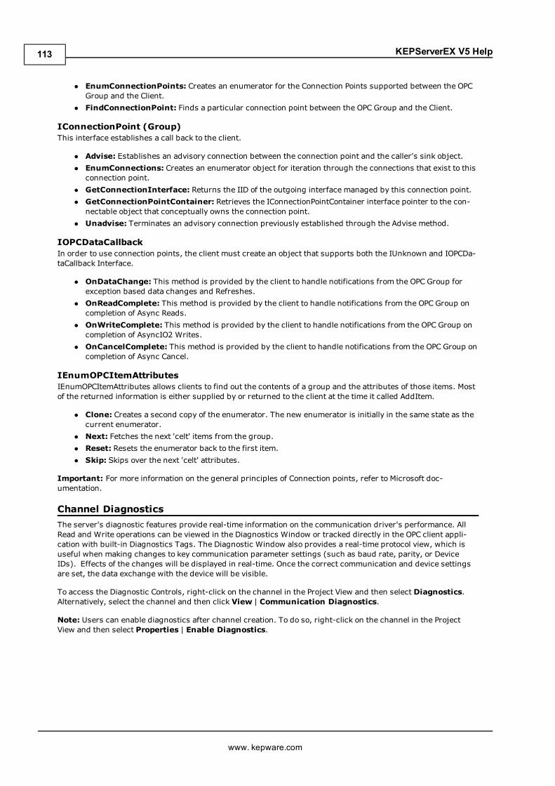
KEPServerEX V5 Help
l EnumConnectionPoints: Creates an enumerator for the Connection Points supported between the OPCGroup and the Client.
l FindConnectionPoint: Finds a particular connection point between the OPC Group and the Client.
IConnectionPoint (Group)This interface establishes a call back to the client.
l Advise: Establishes an advisory connection between the connection point and the caller's sink object.l EnumConnections: Creates an enumerator object for iteration through the connections that exist to thisconnection point.
l GetConnectionInterface: Returns the IID of the outgoing interface managed by this connection point.l GetConnectionPointContainer: Retrieves the IConnectionPointContainer interface pointer to the con-nectable object that conceptually owns the connection point.
l Unadvise: Terminates an advisory connection previously established through the Advise method.
IOPCDataCallbackIn order to use connection points, the client must create an object that supports both the IUnknown and IOPCDa-taCallback Interface.
l OnDataChange: This method is provided by the client to handle notifications from the OPC Group forexception based data changes and Refreshes.
l OnReadComplete: This method is provided by the client to handle notifications from the OPC Group oncompletion of Async Reads.
l OnWriteComplete: This method is provided by the client to handle notifications from the OPC Group oncompletion of AsyncIO2 Writes.
l OnCancelComplete: This method is provided by the client to handle notifications from the OPC Group oncompletion of Async Cancel.
IEnumOPCItemAttributesIEnumOPCItemAttributes allows clients to find out the contents of a group and the attributes of those items. Mostof the returned information is either supplied by or returned to the client at the time it called AddItem.
l Clone: Creates a second copy of the enumerator. The new enumerator is initially in the same state as thecurrent enumerator.
l Next: Fetches the next 'celt' items from the group.l Reset: Resets the enumerator back to the first item.l Skip: Skips over the next 'celt' attributes.
Important: For more information on the general principles of Connection points, refer to Microsoft doc-umentation.
Channel DiagnosticsThe server's diagnostic features provide real-time information on the communication driver's performance. AllRead and Write operations can be viewed in the Diagnostics Window or tracked directly in the OPC client appli-cation with built-in Diagnostics Tags. The Diagnostic Window also provides a real-time protocol view, which isuseful when making changes to key communication parameter settings (such as baud rate, parity, or DeviceIDs). Effects of the changes will be displayed in real-time. Once the correct communication and device settingsare set, the data exchange with the device will be visible.
To access the Diagnostic Controls, right-click on the channel in the Project View and then select Diagnostics.Alternatively, select the channel and then click View | Communication Diagnostics.
Note: Users can enable diagnostics after channel creation. To do so, right-click on the channel in the ProjectView and then select Properties | Enable Diagnostics.
www. kepware.com
113
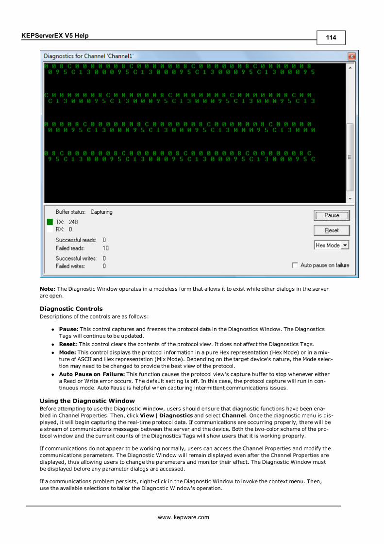
KEPServerEX V5 Help
Note: The Diagnostic Window operates in a modeless form that allows it to exist while other dialogs in the serverare open.
Diagnostic ControlsDescriptions of the controls are as follows:
l Pause: This control captures and freezes the protocol data in the Diagnostics Window. The DiagnosticsTags will continue to be updated.
l Reset: This control clears the contents of the protocol view. It does not affect the Diagnostics Tags.l Mode: This control displays the protocol information in a pure Hex representation (Hex Mode) or in a mix-ture of ASCII and Hex representation (Mix Mode). Depending on the target device's nature, the Mode selec-tion may need to be changed to provide the best view of the protocol.
l Auto Pause on Failure: This function causes the protocol view's capture buffer to stop whenever eithera Read or Write error occurs. The default setting is off. In this case, the protocol capture will run in con-tinuous mode. Auto Pause is helpful when capturing intermittent communications issues.
Using the Diagnostic WindowBefore attempting to use the Diagnostic Window, users should ensure that diagnostic functions have been ena-bled in Channel Properties. Then, click View | Diagnostics and select Channel. Once the diagnostic menu is dis-played, it will begin capturing the real-time protocol data. If communications are occurring properly, there will bea stream of communications messages between the server and the device. Both the two-color scheme of the pro-tocol window and the current counts of the Diagnostics Tags will show users that it is working properly.
If communications do not appear to be working normally, users can access the Channel Properties and modify thecommunications parameters. The Diagnostic Window will remain displayed even after the Channel Properties aredisplayed, thus allowing users to change the parameters and monitor their effect. The Diagnostic Window mustbe displayed before any parameter dialogs are accessed.
If a communications problem persists, right-click in the Diagnostic Window to invoke the context menu. Then,use the available selections to tailor the Diagnostic Window's operation.
www. kepware.com
114
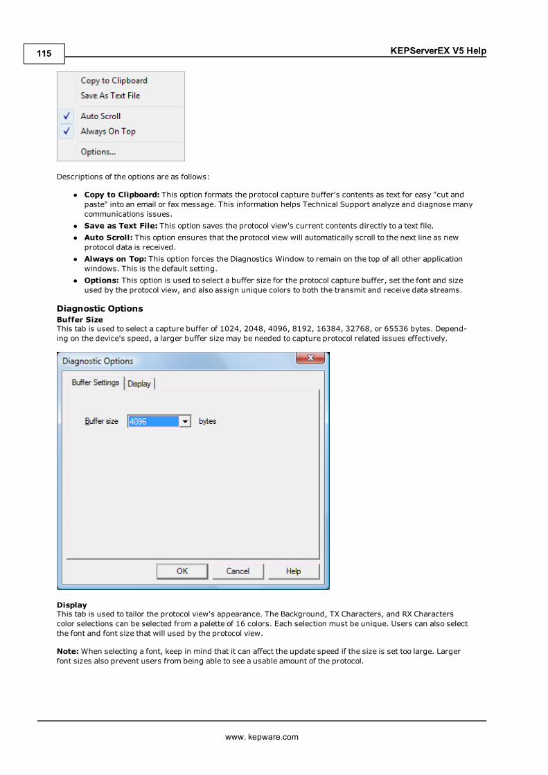
KEPServerEX V5 Help
Descriptions of the options are as follows:
l Copy to Clipboard: This option formats the protocol capture buffer's contents as text for easy "cut andpaste" into an email or fax message. This information helps Technical Support analyze and diagnose manycommunications issues.
l Save as Text File: This option saves the protocol view's current contents directly to a text file.l Auto Scroll: This option ensures that the protocol view will automatically scroll to the next line as newprotocol data is received.
l Always on Top: This option forces the Diagnostics Window to remain on the top of all other applicationwindows. This is the default setting.
l Options: This option is used to select a buffer size for the protocol capture buffer, set the font and sizeused by the protocol view, and also assign unique colors to both the transmit and receive data streams.
Diagnostic OptionsBuffer SizeThis tab is used to select a capture buffer of 1024, 2048, 4096, 8192, 16384, 32768, or 65536 bytes. Depend-ing on the device's speed, a larger buffer size may be needed to capture protocol related issues effectively.
DisplayThis tab is used to tailor the protocol view's appearance. The Background, TX Characters, and RX Characterscolor selections can be selected from a palette of 16 colors. Each selection must be unique. Users can also selectthe font and font size that will used by the protocol view.
Note:When selecting a font, keep in mind that it can affect the update speed if the size is set too large. Largerfont sizes also prevent users from being able to see a usable amount of the protocol.
www. kepware.com
115
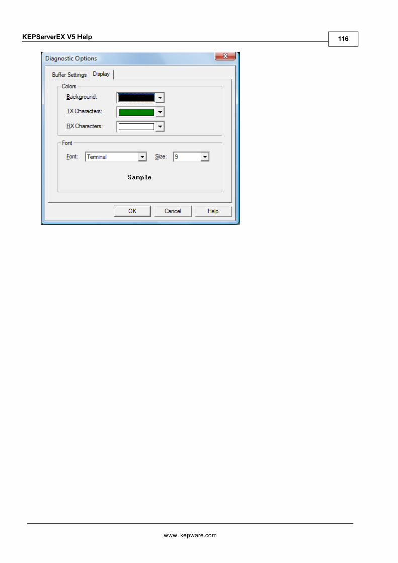
KEPServerEX V5 Help
www. kepware.com
116
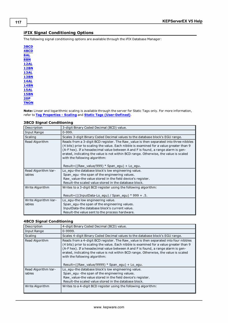
KEPServerEX V5 Help
iFIX Signal Conditioning OptionsThe following signal conditioning options are available through the iFIX Database Manager:
3BCD4BCD8AL8BN12AL12BN13AL13BN14AL14BN15AL15BN20PTNON
Note: Linear and logarithmic scaling is available through the server for Static Tags only. For more information,refer to Tag Properties - Scaling and Static Tags (User-Defined).
3BCD Signal ConditioningDescription 3-digit Binary Coded Decimal (BCD) value.Input Range 0-999.Scaling Scales 3-digit Binary Coded Decimal values to the database block's EGU range.Read Algorithm Reads from a 3-digit BCD register. The Raw_value is then separated into three nibbles
(4 bits) prior to scaling the value. Each nibble is examined for a value greater than 9(A-F hex). If a hexadecimal value between A and F is found, a range alarm is gen-erated, indicating the value is not within BCD range. Otherwise, the value is scaledwith the following algorithm:
Result=((Raw_value/999) * Span_egu) + Lo_egu.Read Algorithm Var-iables
Lo_egu-the database block's low engineering value.Span_egu -the span of the engineering values.Raw_value-the value stored in the field device's register.Result-the scaled value stored in the database block.
Write Algorithm Writes to a 3-digit BCD register using the following algorithm:
Result=(((InputData-Lo_egu) / Span_egu) * 999 + .5.Write Algorithm Var-iables
Lo_egu-the low engineering value.Span_egu-the span of the engineering values.InputData-the database block's current value.Result-the value sent to the process hardware.
4BCD Signal ConditioningDescription 4-digit Binary Coded Decimal (BCD) value.Input Range 0-9999.Scaling Scales 4-digit Binary Coded Decimal values to the database block's EGU range.Read Algorithm Reads from a 4-digit BCD register. The Raw_value is then separated into four nibbles
(4 bits) prior to scaling the value. Each nibble is examined for a value greater than 9(A-F hex). If a hexadecimal value between A and F is found, a range alarm is gen-erated, indicating the value is not within BCD range. Otherwise, the value is scaledwith the following algorithm:
Result=((Raw_value/9999) * Span_egu) + Lo_egu.Read Algorithm Var-iables
Lo_egu-the database block's low engineering value.Span_egu -the span of the engineering values.Raw_value-the value stored in the field device's register.Result-the scaled value stored in the database block.
Write Algorithm Writes to a 4-digit BCD register using the following algorithm:
www. kepware.com
117
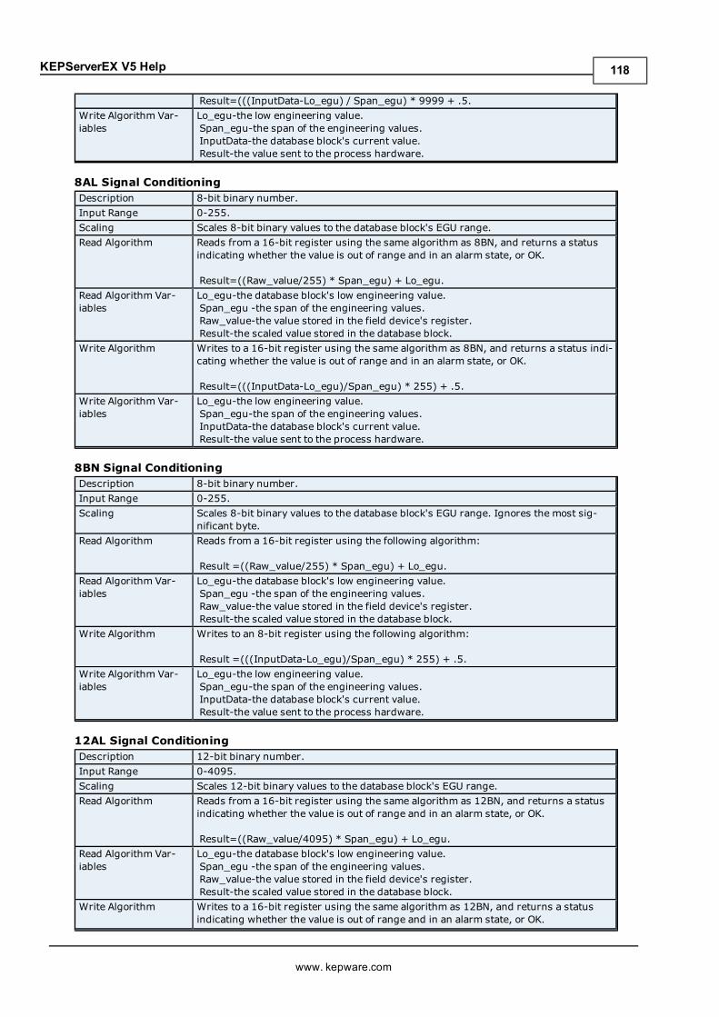
KEPServerEX V5 Help
Result=(((InputData-Lo_egu) / Span_egu) * 9999 + .5.Write Algorithm Var-iables
Lo_egu-the low engineering value.Span_egu-the span of the engineering values.InputData-the database block's current value.Result-the value sent to the process hardware.
8AL Signal ConditioningDescription 8-bit binary number.Input Range 0-255.Scaling Scales 8-bit binary values to the database block's EGU range.Read Algorithm Reads from a 16-bit register using the same algorithm as 8BN, and returns a status
indicating whether the value is out of range and in an alarm state, or OK.
Result=((Raw_value/255) * Span_egu) + Lo_egu.Read Algorithm Var-iables
Lo_egu-the database block's low engineering value.Span_egu -the span of the engineering values.Raw_value-the value stored in the field device's register.Result-the scaled value stored in the database block.
Write Algorithm Writes to a 16-bit register using the same algorithm as 8BN, and returns a status indi-cating whether the value is out of range and in an alarm state, or OK.
Result=(((InputData-Lo_egu)/Span_egu) * 255) + .5.Write Algorithm Var-iables
Lo_egu-the low engineering value.Span_egu-the span of the engineering values.InputData-the database block's current value.Result-the value sent to the process hardware.
8BN Signal ConditioningDescription 8-bit binary number.Input Range 0-255.Scaling Scales 8-bit binary values to the database block's EGU range. Ignores the most sig-
nificant byte.Read Algorithm Reads from a 16-bit register using the following algorithm:
Result =((Raw_value/255) * Span_egu) + Lo_egu.Read Algorithm Var-iables
Lo_egu-the database block's low engineering value.Span_egu -the span of the engineering values.Raw_value-the value stored in the field device's register.Result-the scaled value stored in the database block.
Write Algorithm Writes to an 8-bit register using the following algorithm:
Result =(((InputData-Lo_egu)/Span_egu) * 255) + .5.Write Algorithm Var-iables
Lo_egu-the low engineering value.Span_egu-the span of the engineering values.InputData-the database block's current value.Result-the value sent to the process hardware.
12AL Signal ConditioningDescription 12-bit binary number.Input Range 0-4095.Scaling Scales 12-bit binary values to the database block's EGU range.Read Algorithm Reads from a 16-bit register using the same algorithm as 12BN, and returns a status
indicating whether the value is out of range and in an alarm state, or OK.
Result=((Raw_value/4095) * Span_egu) + Lo_egu.Read Algorithm Var-iables
Lo_egu-the database block's low engineering value.Span_egu -the span of the engineering values.Raw_value-the value stored in the field device's register.Result-the scaled value stored in the database block.
Write Algorithm Writes to a 16-bit register using the same algorithm as 12BN, and returns a statusindicating whether the value is out of range and in an alarm state, or OK.
www. kepware.com
118
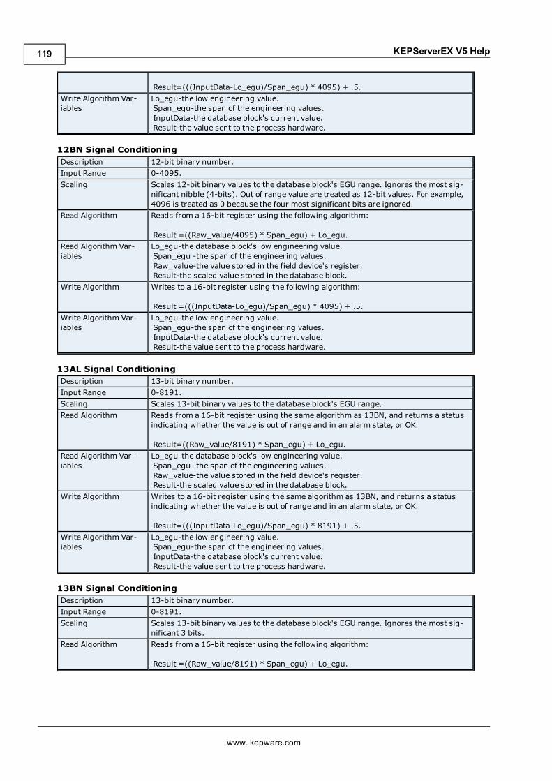
KEPServerEX V5 Help
Result=(((InputData-Lo_egu)/Span_egu) * 4095) + .5.Write Algorithm Var-iables
Lo_egu-the low engineering value.Span_egu-the span of the engineering values.InputData-the database block's current value.Result-the value sent to the process hardware.
12BN Signal ConditioningDescription 12-bit binary number.Input Range 0-4095.Scaling Scales 12-bit binary values to the database block's EGU range. Ignores the most sig-
nificant nibble (4-bits). Out of range value are treated as 12-bit values. For example,4096 is treated as 0 because the four most significant bits are ignored.
Read Algorithm Reads from a 16-bit register using the following algorithm:
Result =((Raw_value/4095) * Span_egu) + Lo_egu.Read Algorithm Var-iables
Lo_egu-the database block's low engineering value.Span_egu -the span of the engineering values.Raw_value-the value stored in the field device's register.Result-the scaled value stored in the database block.
Write Algorithm Writes to a 16-bit register using the following algorithm:
Result =(((InputData-Lo_egu)/Span_egu) * 4095) + .5.Write Algorithm Var-iables
Lo_egu-the low engineering value.Span_egu-the span of the engineering values.InputData-the database block's current value.Result-the value sent to the process hardware.
13AL Signal ConditioningDescription 13-bit binary number.Input Range 0-8191.Scaling Scales 13-bit binary values to the database block's EGU range.Read Algorithm Reads from a 16-bit register using the same algorithm as 13BN, and returns a status
indicating whether the value is out of range and in an alarm state, or OK.
Result=((Raw_value/8191) * Span_egu) + Lo_egu.Read Algorithm Var-iables
Lo_egu-the database block's low engineering value.Span_egu -the span of the engineering values.Raw_value-the value stored in the field device's register.Result-the scaled value stored in the database block.
Write Algorithm Writes to a 16-bit register using the same algorithm as 13BN, and returns a statusindicating whether the value is out of range and in an alarm state, or OK.
Result=(((InputData-Lo_egu)/Span_egu) * 8191) + .5.Write Algorithm Var-iables
Lo_egu-the low engineering value.Span_egu-the span of the engineering values.InputData-the database block's current value.Result-the value sent to the process hardware.
13BN Signal ConditioningDescription 13-bit binary number.Input Range 0-8191.Scaling Scales 13-bit binary values to the database block's EGU range. Ignores the most sig-
nificant 3 bits.Read Algorithm Reads from a 16-bit register using the following algorithm:
Result =((Raw_value/8191) * Span_egu) + Lo_egu.
www. kepware.com
119
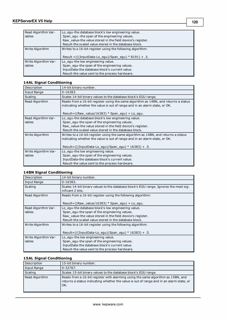
KEPServerEX V5 Help
Read Algorithm Var-iables
Lo_egu-the database block's low engineering value.Span_egu -the span of the engineering values.Raw_value-the value stored in the field device's register.Result-the scaled value stored in the database block.
Write Algorithm Writes to a 16-bit register using the following algorithm:
Result =(((InputData-Lo_egu)/Span_egu) * 8191) + .5.Write Algorithm Var-iables
Lo_egu-the low engineering value.Span_egu-the span of the engineering values.InputData-the database block's current value.Result-the value sent to the process hardware.
14AL Signal ConditioningDescription 14-bit binary number.Input Range 0-16383.Scaling Scales 14-bit binary values to the database block's EGU range.Read Algorithm Reads from a 16-bit register using the same algorithm as 14BN, and returns a status
indicating whether the value is out of range and in an alarm state, or OK.
Result=((Raw_value/16383) * Span_egu) + Lo_egu.Read Algorithm Var-iables
Lo_egu-the database block's low engineering value.Span_egu-the span of the engineering values.Raw_value-the value stored in the field device's register.Result-the scaled value stored in the database block.
Write Algorithm Writes to a 16-bit register using the same algorithm as 14BN, and returns a statusindicating whether the value is out of range and in an alarm state, or OK.
Result=(((InputData-Lo_egu)/Span_egu) * 16383) + .5.Write Algorithm Var-iables
Lo_egu-the low engineering value.Span_egu-the span of the engineering values.InputData-the database block's current value.Result-the value sent to the process hardware.
14BN Signal ConditioningDescription 14-bit binary number.Input Range 0-16383.Scaling Scales 14-bit binary values to the database block's EGU range. Ignores the most sig-
nificant 2 bits.Read Algorithm Reads from a 16-bit register using the following algorithm:
Result=((Raw_value/16383) * Span_egu) + Lo_egu.Read Algorithm Var-iables
Lo_egu-the database block's low engineering value.Span_egu-the span of the engineering values.Raw_value-the value stored in the field device's register.Result-the scaled value stored in the database block.
Write Algorithm Writes to a 16-bit register using the following algorithm:
Result=(((InputData-Lo_egu)/Span_egu) * 16383) + .5.Write Algorithm Var-iables
Lo_egu-the low engineering value.Span_egu-the span of the engineering values.InputData-the database block's current value.Result-the value sent to the process hardware.
15AL Signal ConditioningDescription 15-bit binary number.Input Range 0-32767.Scaling Scales 15-bit binary values to the database block's EGU range.Read Algorithm Reads from a 16-bit register with alarming using the same algorithm as 15BN, and
returns a status indicating whether the value is out of range and in an alarm state, orOK.
www. kepware.com
120
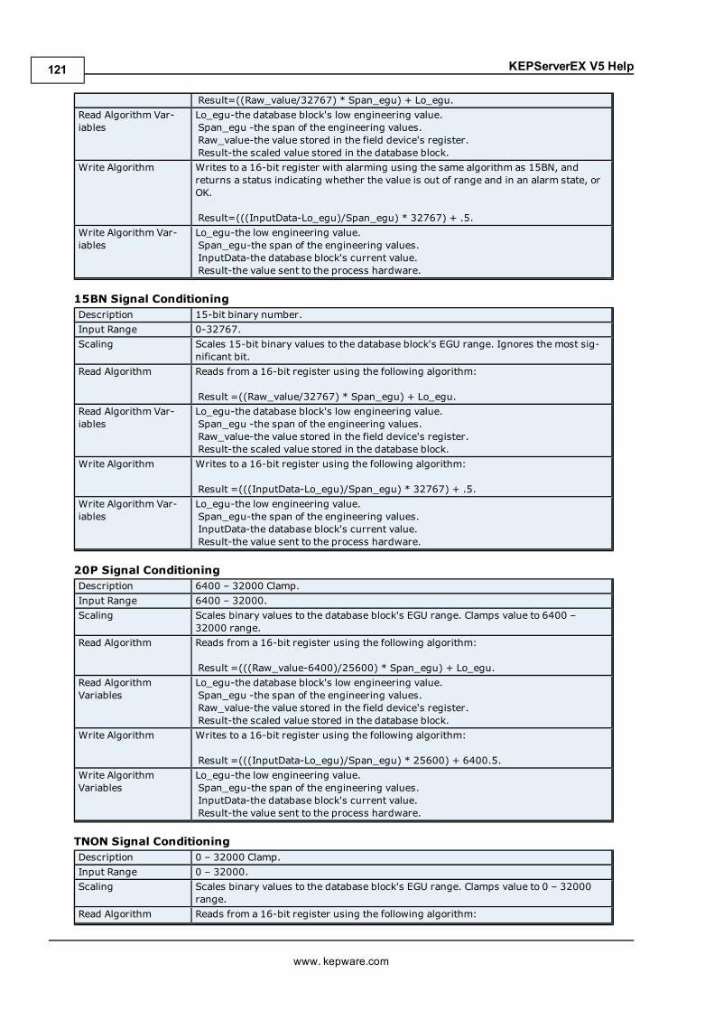
KEPServerEX V5 Help
Result=((Raw_value/32767) * Span_egu) + Lo_egu.Read Algorithm Var-iables
Lo_egu-the database block's low engineering value.Span_egu -the span of the engineering values.Raw_value-the value stored in the field device's register.Result-the scaled value stored in the database block.
Write Algorithm Writes to a 16-bit register with alarming using the same algorithm as 15BN, andreturns a status indicating whether the value is out of range and in an alarm state, orOK.
Result=(((InputData-Lo_egu)/Span_egu) * 32767) + .5.Write Algorithm Var-iables
Lo_egu-the low engineering value.Span_egu-the span of the engineering values.InputData-the database block's current value.Result-the value sent to the process hardware.
15BN Signal ConditioningDescription 15-bit binary number.Input Range 0-32767.Scaling Scales 15-bit binary values to the database block's EGU range. Ignores the most sig-
nificant bit.Read Algorithm Reads from a 16-bit register using the following algorithm:
Result =((Raw_value/32767) * Span_egu) + Lo_egu.Read Algorithm Var-iables
Lo_egu-the database block's low engineering value.Span_egu -the span of the engineering values.Raw_value-the value stored in the field device's register.Result-the scaled value stored in the database block.
Write Algorithm Writes to a 16-bit register using the following algorithm:
Result =(((InputData-Lo_egu)/Span_egu) * 32767) + .5.Write Algorithm Var-iables
Lo_egu-the low engineering value.Span_egu-the span of the engineering values.InputData-the database block's current value.Result-the value sent to the process hardware.
20P Signal ConditioningDescription 6400 – 32000 Clamp.Input Range 6400 – 32000.Scaling Scales binary values to the database block's EGU range. Clamps value to 6400 –
32000 range.Read Algorithm Reads from a 16-bit register using the following algorithm:
Result =(((Raw_value-6400)/25600) * Span_egu) + Lo_egu.Read AlgorithmVariables
Lo_egu-the database block's low engineering value.Span_egu -the span of the engineering values.Raw_value-the value stored in the field device's register.Result-the scaled value stored in the database block.
Write Algorithm Writes to a 16-bit register using the following algorithm:
Result =(((InputData-Lo_egu)/Span_egu) * 25600) + 6400.5.Write AlgorithmVariables
Lo_egu-the low engineering value.Span_egu-the span of the engineering values.InputData-the database block's current value.Result-the value sent to the process hardware.
TNON Signal ConditioningDescription 0 – 32000 Clamp.Input Range 0 – 32000.Scaling Scales binary values to the database block's EGU range. Clamps value to 0 – 32000
range.Read Algorithm Reads from a 16-bit register using the following algorithm:
www. kepware.com
121
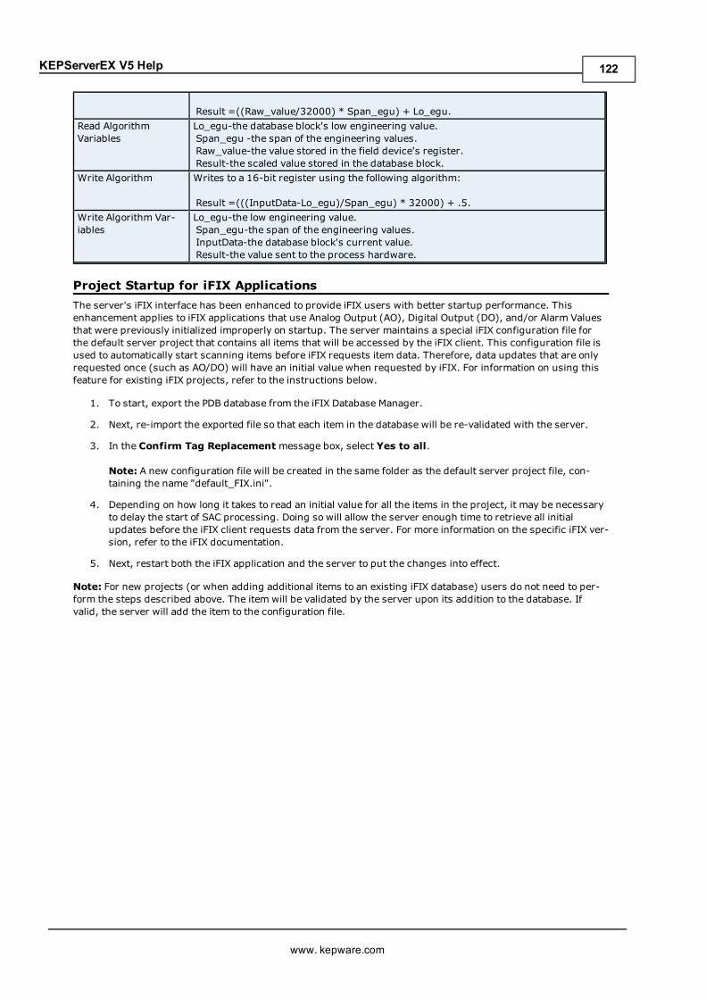
KEPServerEX V5 Help
Result =((Raw_value/32000) * Span_egu) + Lo_egu.Read AlgorithmVariables
Lo_egu-the database block's low engineering value.Span_egu -the span of the engineering values.Raw_value-the value stored in the field device's register.Result-the scaled value stored in the database block.
Write Algorithm Writes to a 16-bit register using the following algorithm:
Result =(((InputData-Lo_egu)/Span_egu) * 32000) + .5.Write Algorithm Var-iables
Lo_egu-the low engineering value.Span_egu-the span of the engineering values.InputData-the database block's current value.Result-the value sent to the process hardware.
Project Startup for iFIX ApplicationsThe server's iFIX interface has been enhanced to provide iFIX users with better startup performance. Thisenhancement applies to iFIX applications that use Analog Output (AO), Digital Output (DO), and/or Alarm Valuesthat were previously initialized improperly on startup. The server maintains a special iFIX configuration file forthe default server project that contains all items that will be accessed by the iFIX client. This configuration file isused to automatically start scanning items before iFIX requests item data. Therefore, data updates that are onlyrequested once (such as AO/DO) will have an initial value when requested by iFIX. For information on using thisfeature for existing iFIX projects, refer to the instructions below.
1. To start, export the PDB database from the iFIX Database Manager.
2. Next, re-import the exported file so that each item in the database will be re-validated with the server.
3. In the Confirm Tag Replacement message box, select Yes to all.
Note: A new configuration file will be created in the same folder as the default server project file, con-taining the name "default_FIX.ini".
4. Depending on how long it takes to read an initial value for all the items in the project, it may be necessaryto delay the start of SAC processing. Doing so will allow the server enough time to retrieve all initialupdates before the iFIX client requests data from the server. For more information on the specific iFIX ver-sion, refer to the iFIX documentation.
5. Next, restart both the iFIX application and the server to put the changes into effect.
Note: For new projects (or when adding additional items to an existing iFIX database) users do not need to per-form the steps described above. The item will be validated by the server upon its addition to the database. Ifvalid, the server will add the item to the configuration file.
www. kepware.com
122
KEPServerEX V5 Help
How Do I...For more information, select a link from the list below.
Allow Desktop InteractionsCreate and Use an AliasOptimize the Server ProjectProcess Array DataProperly Name a Channel, Device, Tag, and Tag GroupResolve Comm Issues When the DNS/DHCP Device Connected to the Server is Power CycledSelect the Correct Network CableUse an Alias to Optimize a ProjectUse DDE with the ServerUse Dynamic Tag AddressingUse Ethernet EncapsulationUse Net DDE Across a Network
How To... Allow Desktop InteractionsSome communication interfaces require the server to interact with the desktop. For example, Windows Mes-saging Layer is used by DDE and FastDDE. It is important that the operating system be taken into considerationwhen choosing how to communicate with the desktop.
Windows Vista, Windows Server 2008, and Later Operating SystemsIn Windows Vista, Windows Server 2008, and later operating systems, services run in an isolated session that isinaccessible to users logged on to the console. These operating systems require that the process mode be set toInteractive. This allows the Runtime to run in the same user account as the current user. For information onchanging the process mode, refer to Settings - Runtime Process.
Windows XP, Windows Server 2003, and Earlier Operating SystemsIn Windows XP, Windows Server 2003, and earlier operating systems, the process mode can remain set as a Sys-tem Service. The Runtime's service, however, must be allowed to interact with the desktop. This is the preferredmode of operation since a user is not required to be logged on to the console in order for the server to start. Forinformation on allowing a service to interact with the desktop, follow the instructions below.
Note: These service settings only apply when the server is running in Service Mode.
1. To start, launch the Services snap-in (which is part of theMicrosoft Management Console). To do so,click Start | Run.
2. Type "services.msc" and clickOK. Then, locate the server by its name in the list of services. Open its con-text menu and select Properties.
3. Next, open the Log On tab and check Allow service to interact with desktop. Then, click Apply.
4. ClickOK to exit.
5. Next, locate the Administration icon. Open its context menu and select Stop Runtime Service.
6. Then, re-open the context menu and select Start Runtime Service.
See Also: Accessing the Administration Menu
How To... Create and Use an AliasComplex Tag Reference ExampleThe image below displays a Complex Tag reference in the server.
www. kepware.com
123
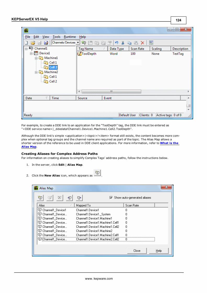
KEPServerEX V5 Help
For example, to create a DDE link to an application for the "ToolDepth" tag, the DDE link must be entered as"<DDE service name>|_ddedata!Channel1.Device1.Machine1.Cell2.ToolDepth".
Although the DDE link's simple <application>|<topic>!<item> format still exists, the content becomes more com-plex when optional tag groups and the channel name are required as part of the topic. The Alias Map allows ashorter version of the reference to be used in DDE client applications. For more information, refer toWhat is theAlias Map.
Creating Aliases for Complex Address PathsFor information on creating aliases to simplify Complex Tags' address paths, follow the instructions below.
1. In the server, click Edit | Alias Map.
2. Click theNew Alias icon, which appears as .
www. kepware.com
124
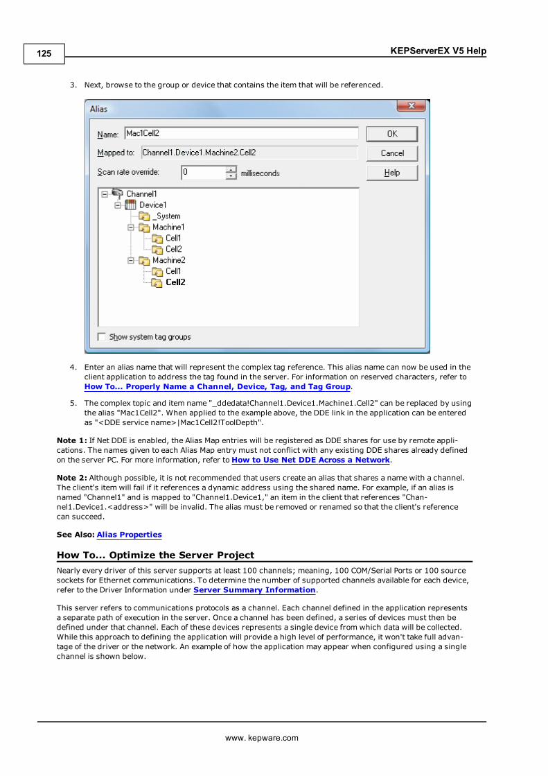
KEPServerEX V5 Help
3. Next, browse to the group or device that contains the item that will be referenced.
4. Enter an alias name that will represent the complex tag reference. This alias name can now be used in theclient application to address the tag found in the server. For information on reserved characters, refer toHow To... Properly Name a Channel, Device, Tag, and Tag Group.
5. The complex topic and item name "_ddedata!Channel1.Device1.Machine1.Cell2" can be replaced by usingthe alias "Mac1Cell2". When applied to the example above, the DDE link in the application can be enteredas "<DDE service name>|Mac1Cell2!ToolDepth".
Note 1: If Net DDE is enabled, the Alias Map entries will be registered as DDE shares for use by remote appli-cations. The names given to each Alias Map entry must not conflict with any existing DDE shares already definedon the server PC. For more information, refer toHow to Use Net DDE Across a Network.
Note 2: Although possible, it is not recommended that users create an alias that shares a name with a channel.The client's item will fail if it references a dynamic address using the shared name. For example, if an alias isnamed "Channel1" and is mapped to "Channel1.Device1," an item in the client that references "Chan-nel1.Device1.<address>" will be invalid. The alias must be removed or renamed so that the client's referencecan succeed.
See Also: Alias Properties
How To... Optimize the Server ProjectNearly every driver of this server supports at least 100 channels; meaning, 100 COM/Serial Ports or 100 sourcesockets for Ethernet communications. To determine the number of supported channels available for each device,refer to the Driver Information under Server Summary Information.
This server refers to communications protocols as a channel. Each channel defined in the application representsa separate path of execution in the server. Once a channel has been defined, a series of devices must then bedefined under that channel. Each of these devices represents a single device from which data will be collected.While this approach to defining the application will provide a high level of performance, it won't take full advan-tage of the driver or the network. An example of how the application may appear when configured using a singlechannel is shown below.
www. kepware.com
125
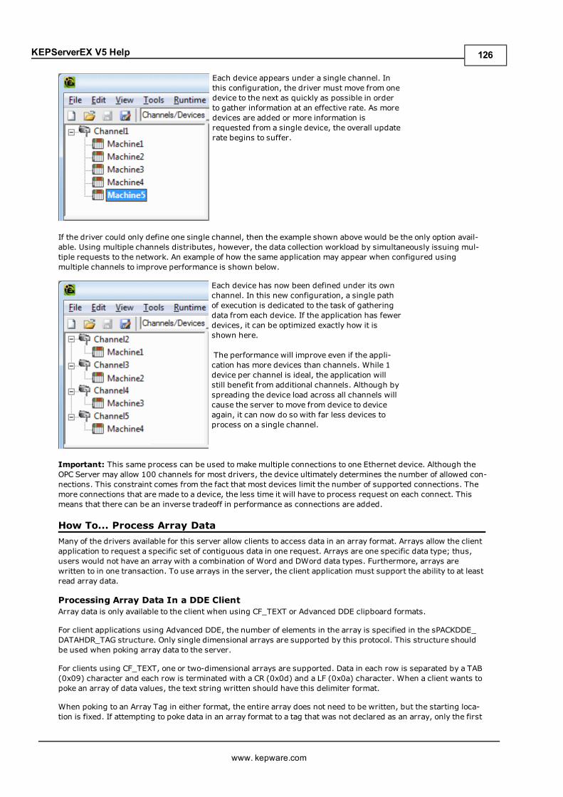
KEPServerEX V5 Help
Each device appears under a single channel. Inthis configuration, the driver must move from onedevice to the next as quickly as possible in orderto gather information at an effective rate. As moredevices are added or more information isrequested from a single device, the overall updaterate begins to suffer.
If the driver could only define one single channel, then the example shown above would be the only option avail-able. Using multiple channels distributes, however, the data collection workload by simultaneously issuing mul-tiple requests to the network. An example of how the same application may appear when configured usingmultiple channels to improve performance is shown below.
Each device has now been defined under its ownchannel. In this new configuration, a single pathof execution is dedicated to the task of gatheringdata from each device. If the application has fewerdevices, it can be optimized exactly how it isshown here.
The performance will improve even if the appli-cation has more devices than channels. While 1device per channel is ideal, the application willstill benefit from additional channels. Although byspreading the device load across all channels willcause the server to move from device to deviceagain, it can now do so with far less devices toprocess on a single channel.
Important: This same process can be used to make multiple connections to one Ethernet device. Although theOPC Server may allow 100 channels for most drivers, the device ultimately determines the number of allowed con-nections. This constraint comes from the fact that most devices limit the number of supported connections. Themore connections that are made to a device, the less time it will have to process request on each connect. Thismeans that there can be an inverse tradeoff in performance as connections are added.
How To... Process Array DataMany of the drivers available for this server allow clients to access data in an array format. Arrays allow the clientapplication to request a specific set of contiguous data in one request. Arrays are one specific data type; thus,users would not have an array with a combination of Word and DWord data types. Furthermore, arrays arewritten to in one transaction. To use arrays in the server, the client application must support the ability to at leastread array data.
Processing Array Data In a DDE ClientArray data is only available to the client when using CF_TEXT or Advanced DDE clipboard formats.
For client applications using Advanced DDE, the number of elements in the array is specified in the sPACKDDE_DATAHDR_TAG structure. Only single dimensional arrays are supported by this protocol. This structure shouldbe used when poking array data to the server.
For clients using CF_TEXT, one or two-dimensional arrays are supported. Data in each row is separated by a TAB(0x09) character and each row is terminated with a CR (0x0d) and a LF (0x0a) character. When a client wants topoke an array of data values, the text string written should have this delimiter format.
When poking to an Array Tag in either format, the entire array does not need to be written, but the starting loca-tion is fixed. If attempting to poke data in an array format to a tag that was not declared as an array, only the first
www. kepware.com
126
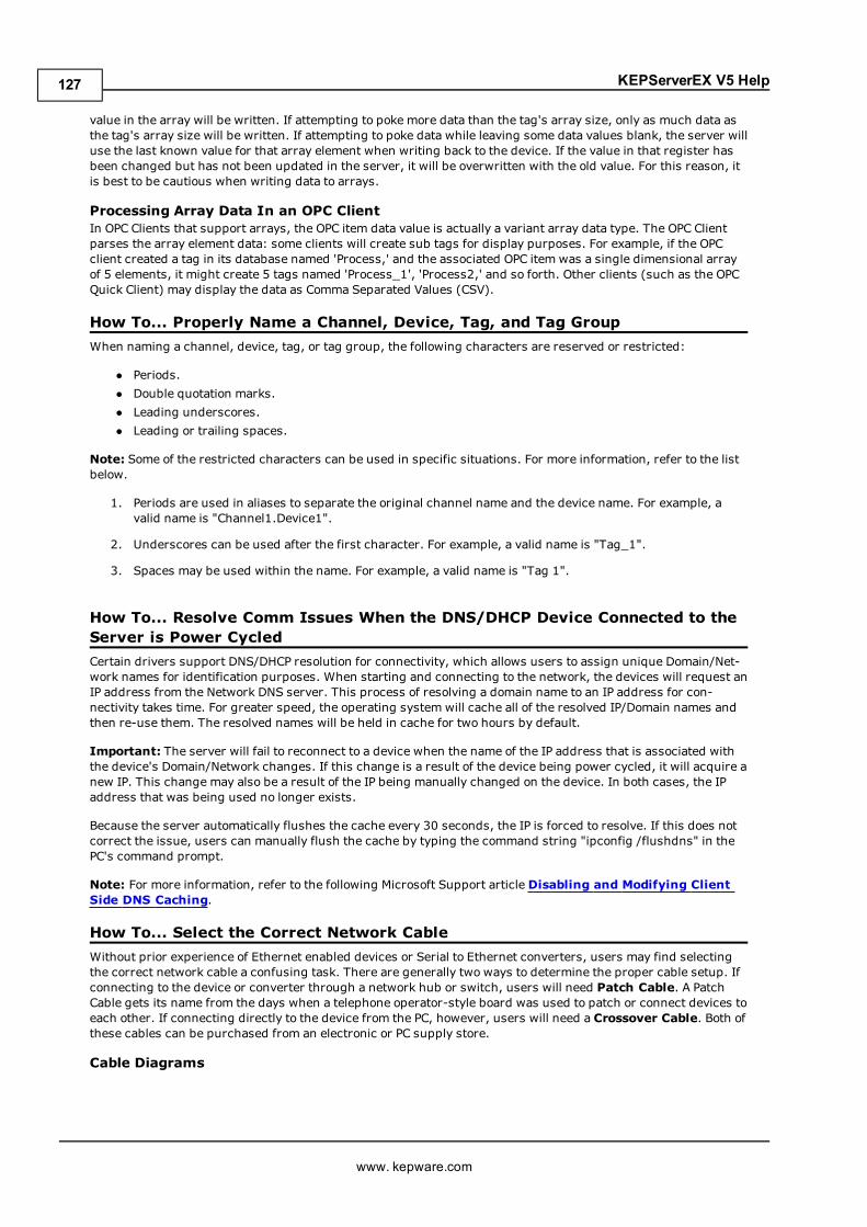
KEPServerEX V5 Help
value in the array will be written. If attempting to poke more data than the tag's array size, only as much data asthe tag's array size will be written. If attempting to poke data while leaving some data values blank, the server willuse the last known value for that array element when writing back to the device. If the value in that register hasbeen changed but has not been updated in the server, it will be overwritten with the old value. For this reason, itis best to be cautious when writing data to arrays.
Processing Array Data In an OPC ClientIn OPC Clients that support arrays, the OPC item data value is actually a variant array data type. The OPC Clientparses the array element data: some clients will create sub tags for display purposes. For example, if the OPCclient created a tag in its database named 'Process,' and the associated OPC item was a single dimensional arrayof 5 elements, it might create 5 tags named 'Process_1', 'Process2,' and so forth. Other clients (such as the OPCQuick Client) may display the data as Comma Separated Values (CSV).
How To... Properly Name a Channel, Device, Tag, and Tag GroupWhen naming a channel, device, tag, or tag group, the following characters are reserved or restricted:
l Periods.l Double quotation marks.l Leading underscores.l Leading or trailing spaces.
Note: Some of the restricted characters can be used in specific situations. For more information, refer to the listbelow.
1. Periods are used in aliases to separate the original channel name and the device name. For example, avalid name is "Channel1.Device1".
2. Underscores can be used after the first character. For example, a valid name is "Tag_1".
3. Spaces may be used within the name. For example, a valid name is "Tag 1".
How To... Resolve Comm Issues When the DNS/DHCP Device Connected to theServer is Power CycledCertain drivers support DNS/DHCP resolution for connectivity, which allows users to assign unique Domain/Net-work names for identification purposes. When starting and connecting to the network, the devices will request anIP address from the Network DNS server. This process of resolving a domain name to an IP address for con-nectivity takes time. For greater speed, the operating system will cache all of the resolved IP/Domain names andthen re-use them. The resolved names will be held in cache for two hours by default.
Important: The server will fail to reconnect to a device when the name of the IP address that is associated withthe device's Domain/Network changes. If this change is a result of the device being power cycled, it will acquire anew IP. This change may also be a result of the IP being manually changed on the device. In both cases, the IPaddress that was being used no longer exists.
Because the server automatically flushes the cache every 30 seconds, the IP is forced to resolve. If this does notcorrect the issue, users can manually flush the cache by typing the command string "ipconfig /flushdns" in thePC's command prompt.
Note: For more information, refer to the following Microsoft Support articleDisabling and Modifying ClientSide DNS Caching.
How To... Select the Correct Network CableWithout prior experience of Ethernet enabled devices or Serial to Ethernet converters, users may find selectingthe correct network cable a confusing task. There are generally two ways to determine the proper cable setup. Ifconnecting to the device or converter through a network hub or switch, users will need Patch Cable. A PatchCable gets its name from the days when a telephone operator-style board was used to patch or connect devices toeach other. If connecting directly to the device from the PC, however, users will need a Crossover Cable. Both ofthese cables can be purchased from an electronic or PC supply store.
Cable Diagrams
www. kepware.com
127
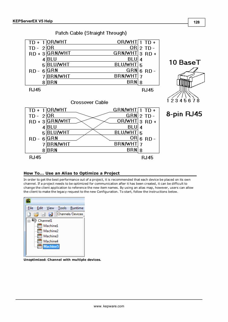
KEPServerEX V5 Help
How To... Use an Alias to Optimize a ProjectIn order to get the best performance out of a project, it is recommended that each device be placed on its ownchannel. If a project needs to be optimized for communication after it has been created, it can be difficult tochange the client application to reference the new item names. By using an alias map, however, users can allowthe client to make the legacy request to the new Configuration. To start, follow the instructions below.
Unoptimized: Channel with multiple devices.
www. kepware.com
128
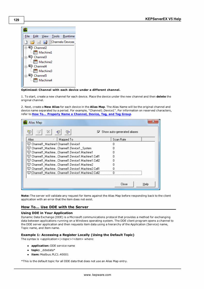
KEPServerEX V5 Help
Optimized: Channel with each device under a different channel.
1. To start, create a new channel for each device. Place the device under the new channel and then delete theoriginal channel.
2. Next, create aNew Alias for each device in the Alias Map. The Alias Name will be the original channel anddevice name separated by a period. For example, "Channel1.Device1". For information on reserved characters,refer toHow To... Properly Name a Channel, Device, Tag, and Tag Group.
Note: The server will validate any request for items against the Alias Map before responding back to the clientapplication with an error that the item does not exist.
How To... Use DDE with the ServerUsing DDE in Your ApplicationDynamic Data Exchange (DDE) is a Microsoft communications protocol that provides a method for exchangingdata between applications running on a Windows operating system. The DDE client program opens a channel tothe DDE server application and then requests item data using a hierarchy of the Application (Service) name,Topic name, and Item name.
Example 1: Accessing a Register Locally (Using the Default Topic)The syntax is <application>|<topic>!<item> where:
l application: DDE service namel topic: _ddedata*l item: Modbus.PLC1.40001
*This is the default topic for all DDE data that does not use an Alias Map entry.
www. kepware.com
129
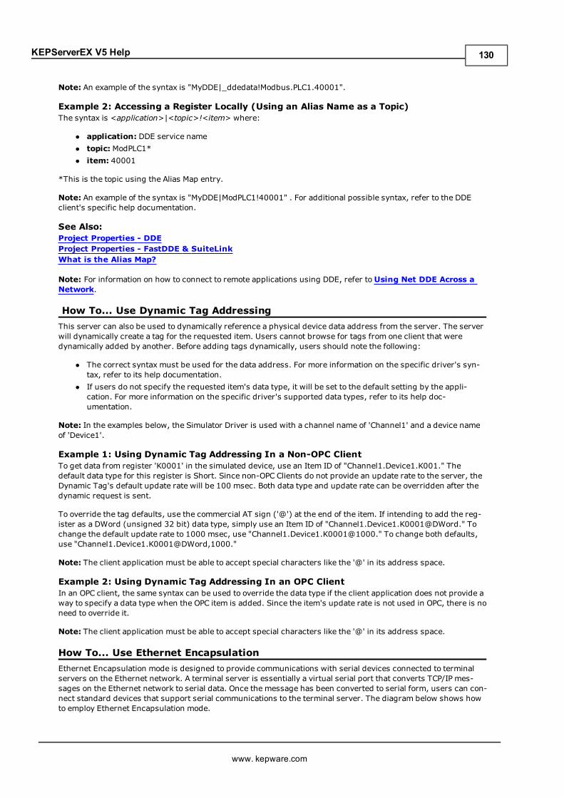
KEPServerEX V5 Help
Note: An example of the syntax is "MyDDE|_ddedata!Modbus.PLC1.40001".
Example 2: Accessing a Register Locally (Using an Alias Name as a Topic)The syntax is <application>|<topic>!<item> where:
l application: DDE service namel topic: ModPLC1*l item: 40001
*This is the topic using the Alias Map entry.
Note: An example of the syntax is "MyDDE|ModPLC1!40001" . For additional possible syntax, refer to the DDEclient's specific help documentation.
See Also:Project Properties - DDEProject Properties - FastDDE & SuiteLinkWhat is the Alias Map?
Note: For information on how to connect to remote applications using DDE, refer toUsing Net DDE Across aNetwork.
How To... Use Dynamic Tag AddressingThis server can also be used to dynamically reference a physical device data address from the server. The serverwill dynamically create a tag for the requested item. Users cannot browse for tags from one client that weredynamically added by another. Before adding tags dynamically, users should note the following:
l The correct syntax must be used for the data address. For more information on the specific driver's syn-tax, refer to its help documentation.
l If users do not specify the requested item's data type, it will be set to the default setting by the appli-cation. For more information on the specific driver's supported data types, refer to its help doc-umentation.
Note: In the examples below, the Simulator Driver is used with a channel name of 'Channel1' and a device nameof 'Device1'.
Example 1: Using Dynamic Tag Addressing In a Non-OPC ClientTo get data from register 'K0001' in the simulated device, use an Item ID of "Channel1.Device1.K001." Thedefault data type for this register is Short. Since non-OPC Clients do not provide an update rate to the server, theDynamic Tag's default update rate will be 100 msec. Both data type and update rate can be overridden after thedynamic request is sent.
To override the tag defaults, use the commercial AT sign ('@') at the end of the item. If intending to add the reg-ister as a DWord (unsigned 32 bit) data type, simply use an Item ID of "Channel1.Device1.K0001@DWord." Tochange the default update rate to 1000 msec, use "Channel1.Device1.K0001@1000." To change both defaults,use "Channel1.Device1.K0001@DWord,1000."
Note: The client application must be able to accept special characters like the '@' in its address space.
Example 2: Using Dynamic Tag Addressing In an OPC ClientIn an OPC client, the same syntax can be used to override the data type if the client application does not provide away to specify a data type when the OPC item is added. Since the item's update rate is not used in OPC, there is noneed to override it.
Note: The client application must be able to accept special characters like the '@' in its address space.
How To... Use Ethernet EncapsulationEthernet Encapsulation mode is designed to provide communications with serial devices connected to terminalservers on the Ethernet network. A terminal server is essentially a virtual serial port that converts TCP/IP mes-sages on the Ethernet network to serial data. Once the message has been converted to serial form, users can con-nect standard devices that support serial communications to the terminal server. The diagram below shows howto employ Ethernet Encapsulation mode.
www. kepware.com
130
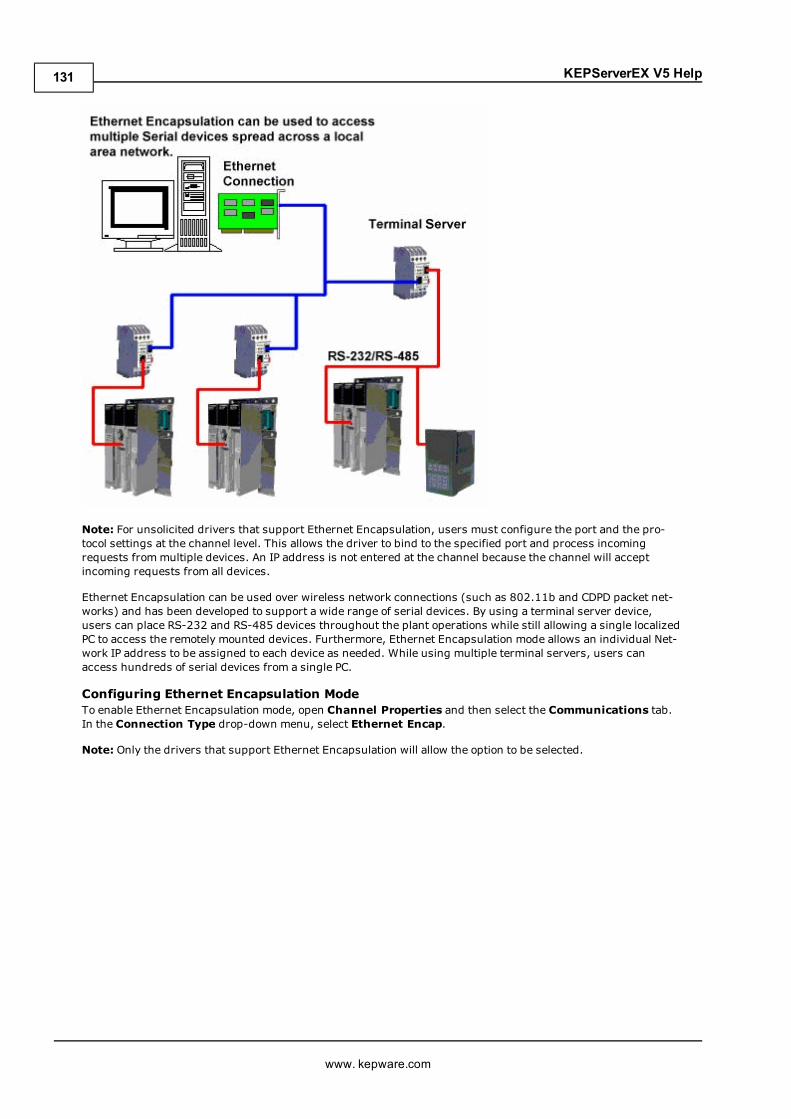
KEPServerEX V5 Help
Note: For unsolicited drivers that support Ethernet Encapsulation, users must configure the port and the pro-tocol settings at the channel level. This allows the driver to bind to the specified port and process incomingrequests frommultiple devices. An IP address is not entered at the channel because the channel will acceptincoming requests from all devices.
Ethernet Encapsulation can be used over wireless network connections (such as 802.11b and CDPD packet net-works) and has been developed to support a wide range of serial devices. By using a terminal server device,users can place RS-232 and RS-485 devices throughout the plant operations while still allowing a single localizedPC to access the remotely mounted devices. Furthermore, Ethernet Encapsulation mode allows an individual Net-work IP address to be assigned to each device as needed. While using multiple terminal servers, users canaccess hundreds of serial devices from a single PC.
Configuring Ethernet Encapsulation ModeTo enable Ethernet Encapsulation mode, open Channel Properties and then select the Communications tab.In the Connection Type drop-down menu, select Ethernet Encap.
Note: Only the drivers that support Ethernet Encapsulation will allow the option to be selected.
www. kepware.com
131
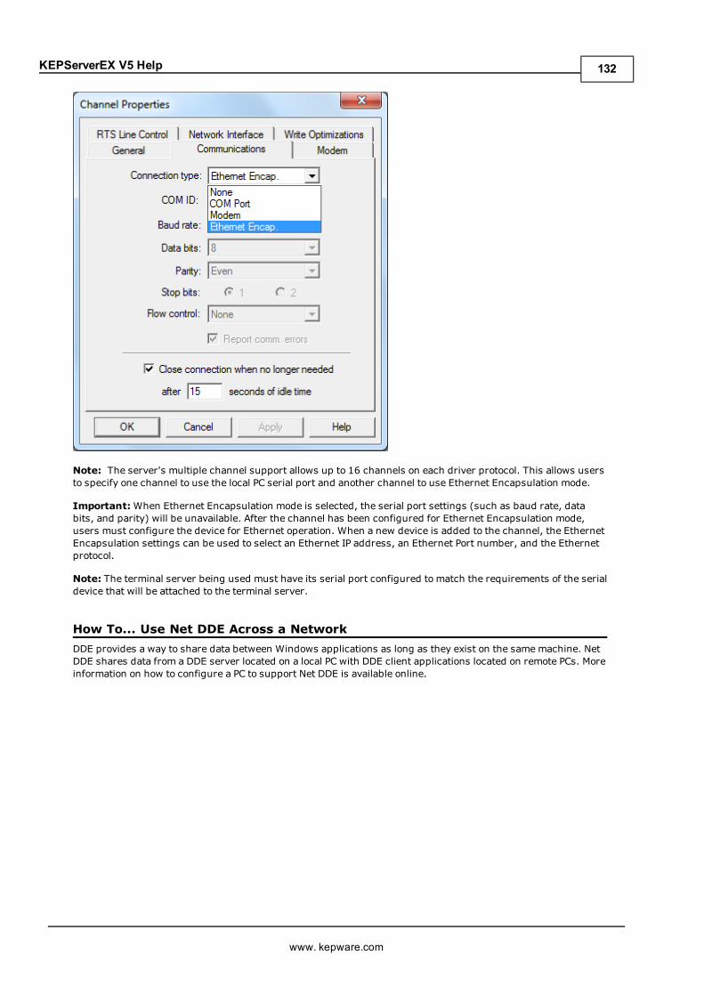
KEPServerEX V5 Help
Note: The server's multiple channel support allows up to 16 channels on each driver protocol. This allows usersto specify one channel to use the local PC serial port and another channel to use Ethernet Encapsulation mode.
Important:When Ethernet Encapsulation mode is selected, the serial port settings (such as baud rate, databits, and parity) will be unavailable. After the channel has been configured for Ethernet Encapsulation mode,users must configure the device for Ethernet operation. When a new device is added to the channel, the EthernetEncapsulation settings can be used to select an Ethernet IP address, an Ethernet Port number, and the Ethernetprotocol.
Note: The terminal server being used must have its serial port configured to match the requirements of the serialdevice that will be attached to the terminal server.
How To... Use Net DDE Across a NetworkDDE provides a way to share data between Windows applications as long as they exist on the samemachine. NetDDE shares data from a DDE server located on a local PC with DDE client applications located on remote PCs. Moreinformation on how to configure a PC to support Net DDE is available online.
www. kepware.com
132
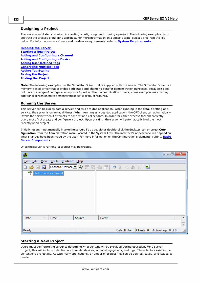
KEPServerEX V5 Help
Designing a ProjectThere are several steps required in creating, configuring, and running a project. The following examples dem-onstrate the process of building a project. For more information on a specific topic, select a link from the listbelow. For information on software and hardware requirements, refer to System Requirements.
Running the ServerStarting a New ProjectAdding and Configuring a ChannelAdding and Configuring a DeviceAdding User-Defined TagsGenerating Multiple TagsAdding Tag ScalingSaving the ProjectTesting the Project
Note: The following examples use the Simulator Driver that is supplied with the server. The Simulator Driver is amemory-based driver that provides both static and changing data for demonstration purposes. Because it doesnot have the range of configuration options found in other communication drivers, some examples may displayadditional screen shots to demonstrate specific product features.
Running the ServerThis server can be run as both a service and as a desktop application. When running in the default setting as aservice, the server is online at all times. When running as a desktop application, the OPC client can automaticallyinvoke the server when it attempts to connect and collect data. In order for either process to work correctly,users must first create and configure a project. Upon starting, the server will automatically load the mostrecently used project.
Initially, users must manually invoke the server. To do so, either double-click the desktop icon or select Con-figuration from the Administration menu located in the System Tray. The interface's appearance will depend onwhat changes have been made by the user. For more information on the Configuration's elements, refer to BasicServer Components.
Once the server is running, a project may be created.
Starting a New ProjectUsers must configure the server to determine what content will be provided during operation. For a serverproject, this will include definition of channels, devices, optional tag groups, and tags. These factors exist in thecontext of a project file. As with many applications, a number of project files can be defined, saved, and loaded asneeded.
www. kepware.com
133
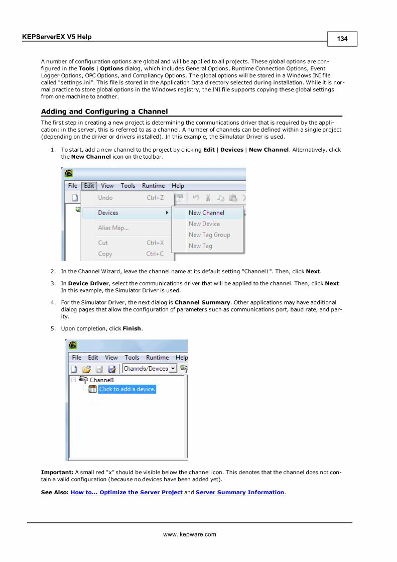
KEPServerEX V5 Help
A number of configuration options are global and will be applied to all projects. These global options are con-figured in the Tools | Options dialog, which includes General Options, Runtime Connection Options, EventLogger Options, OPC Options, and Compliancy Options. The global options will be stored in a Windows INI filecalled "settings.ini". This file is stored in the Application Data directory selected during installation. While it is nor-mal practice to store global options in the Windows registry, the INI file supports copying these global settingsfrom one machine to another.
Adding and Configuring a ChannelThe first step in creating a new project is determining the communications driver that is required by the appli-cation: in the server, this is referred to as a channel. A number of channels can be defined within a single project(depending on the driver or drivers installed). In this example, the Simulator Driver is used.
1. To start, add a new channel to the project by clicking Edit | Devices | New Channel. Alternatively, clicktheNew Channel icon on the toolbar.
2. In the Channel Wizard, leave the channel name at its default setting "Channel1". Then, click Next.
3. In Device Driver, select the communications driver that will be applied to the channel. Then, click Next.In this example, the Simulator Driver is used.
4. For the Simulator Driver, the next dialog is Channel Summary. Other applications may have additionaldialog pages that allow the configuration of parameters such as communications port, baud rate, and par-ity.
5. Upon completion, click Finish.
Important: A small red "x" should be visible below the channel icon. This denotes that the channel does not con-tain a valid configuration (because no devices have been added yet).
See Also: How to... Optimize the Server Project and Server Summary Information.
www. kepware.com
134
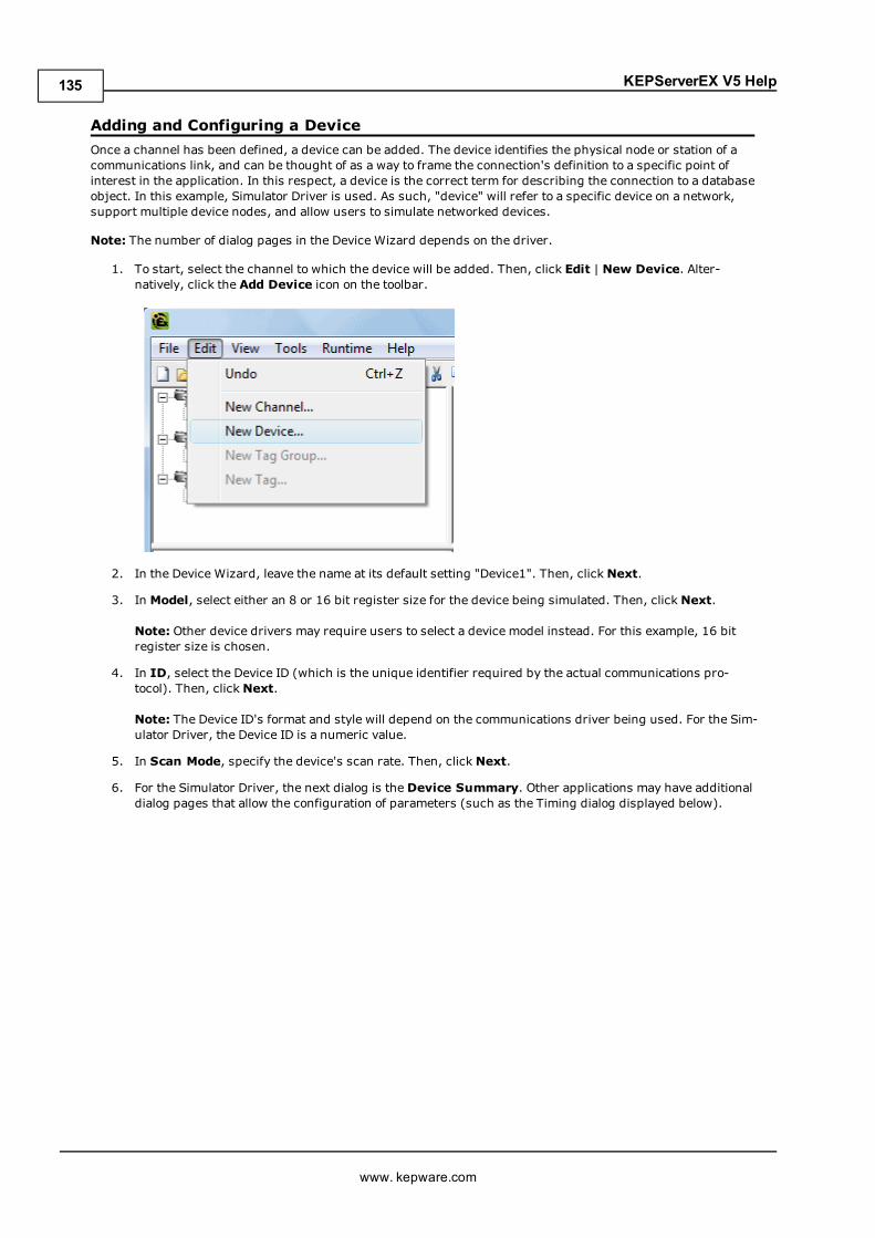
KEPServerEX V5 Help
Adding and Configuring a DeviceOnce a channel has been defined, a device can be added. The device identifies the physical node or station of acommunications link, and can be thought of as a way to frame the connection's definition to a specific point ofinterest in the application. In this respect, a device is the correct term for describing the connection to a databaseobject. In this example, Simulator Driver is used. As such, "device" will refer to a specific device on a network,support multiple device nodes, and allow users to simulate networked devices.
Note: The number of dialog pages in the Device Wizard depends on the driver.
1. To start, select the channel to which the device will be added. Then, click Edit | New Device. Alter-natively, click the Add Device icon on the toolbar.
2. In the Device Wizard, leave the name at its default setting "Device1". Then, click Next.
3. In Model, select either an 8 or 16 bit register size for the device being simulated. Then, click Next.
Note: Other device drivers may require users to select a device model instead. For this example, 16 bitregister size is chosen.
4. In ID, select the Device ID (which is the unique identifier required by the actual communications pro-tocol). Then, clickNext.
Note: The Device ID's format and style will depend on the communications driver being used. For the Sim-ulator Driver, the Device ID is a numeric value.
5. In Scan Mode, specify the device's scan rate. Then, clickNext.
6. For the Simulator Driver, the next dialog is the Device Summary. Other applications may have additionaldialog pages that allow the configuration of parameters (such as the Timing dialog displayed below).
www. kepware.com
135
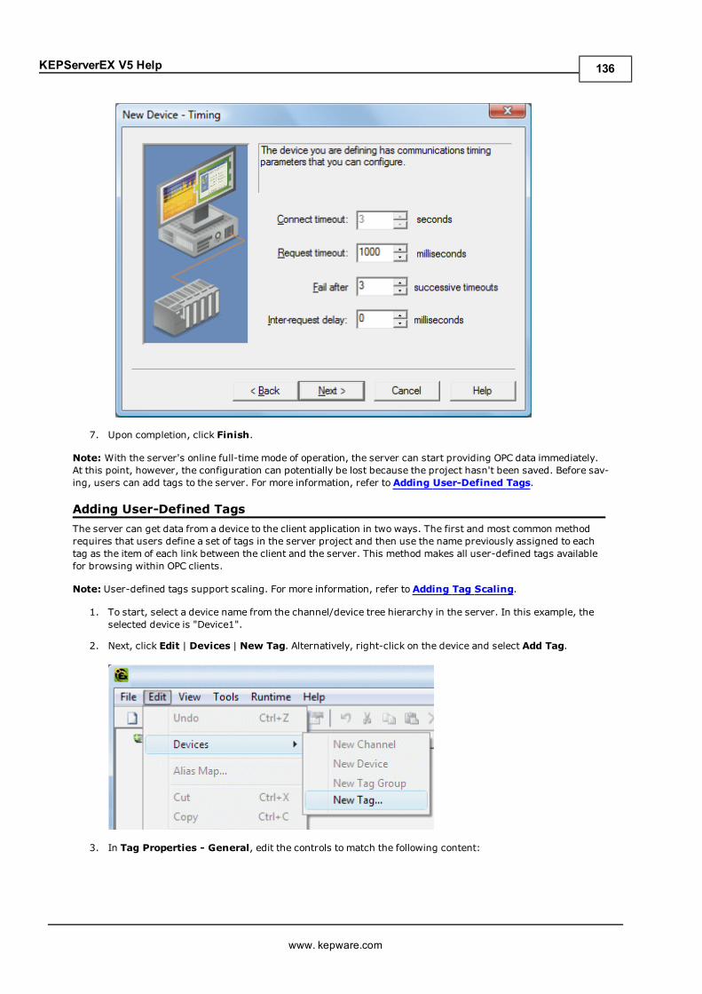
KEPServerEX V5 Help
7. Upon completion, click Finish.
Note: With the server's online full-time mode of operation, the server can start providing OPC data immediately.At this point, however, the configuration can potentially be lost because the project hasn't been saved. Before sav-ing, users can add tags to the server. For more information, refer to Adding User-Defined Tags.
Adding User-Defined TagsThe server can get data from a device to the client application in two ways. The first and most common methodrequires that users define a set of tags in the server project and then use the name previously assigned to eachtag as the item of each link between the client and the server. This method makes all user-defined tags availablefor browsing within OPC clients.
Note: User-defined tags support scaling. For more information, refer to Adding Tag Scaling.
1. To start, select a device name from the channel/device tree hierarchy in the server. In this example, theselected device is "Device1".
2. Next, click Edit | Devices | New Tag. Alternatively, right-click on the device and select Add Tag.
3. In Tag Properties - General, edit the controls to match the following content:
www. kepware.com
136
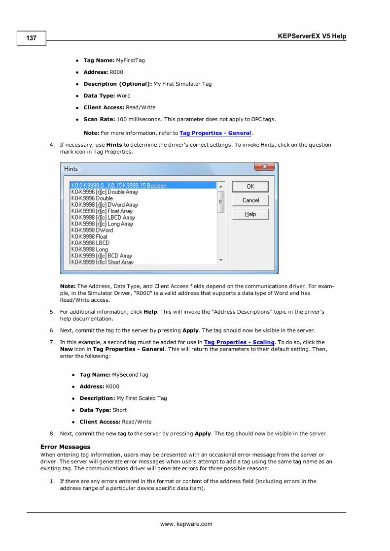
KEPServerEX V5 Help
l Tag Name: MyFirstTag
l Address: R000
l Description (Optional):My First Simulator Tag
l Data Type:Word
l Client Access: Read/Write
l Scan Rate: 100 milliseconds. This parameter does not apply to OPC tags.
Note: For more information, refer to Tag Properties - General.
4. If necessary, useHints to determine the driver's correct settings. To invoke Hints, click on the questionmark icon in Tag Properties.
Note: The Address, Data Type, and Client Access fields depend on the communications driver. For exam-ple, in the Simulator Driver, "R000" is a valid address that supports a data type of Word and hasRead/Write access.
5. For additional information, clickHelp. This will invoke the "Address Descriptions" topic in the driver'shelp documentation.
6. Next, commit the tag to the server by pressing Apply. The tag should now be visible in the server.
7. In this example, a second tag must be added for use in Tag Properties - Scaling. To do so, click theNew icon in Tag Properties - General. This will return the parameters to their default setting. Then,enter the following:
l Tag Name: MySecondTag
l Address: K000
l Description:My First Scaled Tag
l Data Type: Short
l Client Access: Read/Write
8. Next, commit the new tag to the server by pressing Apply. The tag should now be visible in the server.
Error MessagesWhen entering tag information, users may be presented with an occasional error message from the server ordriver. The server will generate error messages when users attempt to add a tag using the same tag name as anexisting tag. The communications driver will generate errors for three possible reasons:
1. If there are any errors entered in the format or content of the address field (including errors in theaddress range of a particular device specific data item).
www. kepware.com
137
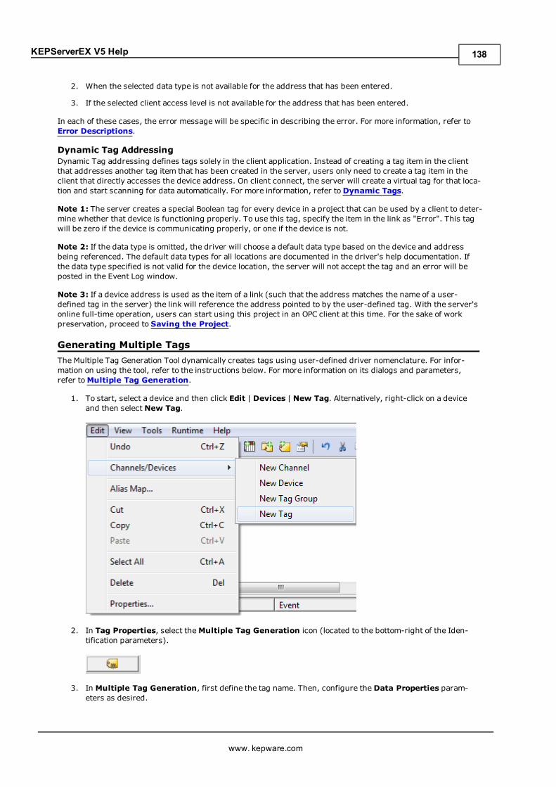
KEPServerEX V5 Help
2. When the selected data type is not available for the address that has been entered.
3. If the selected client access level is not available for the address that has been entered.
In each of these cases, the error message will be specific in describing the error. For more information, refer toError Descriptions.
Dynamic Tag AddressingDynamic Tag addressing defines tags solely in the client application. Instead of creating a tag item in the clientthat addresses another tag item that has been created in the server, users only need to create a tag item in theclient that directly accesses the device address. On client connect, the server will create a virtual tag for that loca-tion and start scanning for data automatically. For more information, refer toDynamic Tags.
Note 1: The server creates a special Boolean tag for every device in a project that can be used by a client to deter-mine whether that device is functioning properly. To use this tag, specify the item in the link as "Error". This tagwill be zero if the device is communicating properly, or one if the device is not.
Note 2: If the data type is omitted, the driver will choose a default data type based on the device and addressbeing referenced. The default data types for all locations are documented in the driver's help documentation. Ifthe data type specified is not valid for the device location, the server will not accept the tag and an error will beposted in the Event Log window.
Note 3: If a device address is used as the item of a link (such that the address matches the name of a user-defined tag in the server) the link will reference the address pointed to by the user-defined tag. With the server'sonline full-time operation, users can start using this project in an OPC client at this time. For the sake of workpreservation, proceed to Saving the Project.
Generating Multiple TagsThe Multiple Tag Generation Tool dynamically creates tags using user-defined driver nomenclature. For infor-mation on using the tool, refer to the instructions below. For more information on its dialogs and parameters,refer toMultiple Tag Generation.
1. To start, select a device and then click Edit | Devices | New Tag. Alternatively, right-click on a deviceand then select New Tag.
2. In Tag Properties, select theMultiple Tag Generation icon (located to the bottom-right of the Iden-tification parameters).
3. In Multiple Tag Generation, first define the tag name. Then, configure the Data Properties param-eters as desired.
www. kepware.com
138
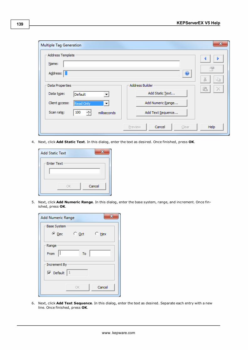
KEPServerEX V5 Help
4. Next, click Add Static Text. In this dialog, enter the text as desired. Once finished, press OK.
5. Next, click Add Numeric Range. In this dialog, enter the base system, range, and increment. Once fin-ished, press OK.
6. Next, click Add Text Sequence. In this dialog, enter the text as desired. Separate each entry with a newline. Once finished, press OK.
www. kepware.com
139
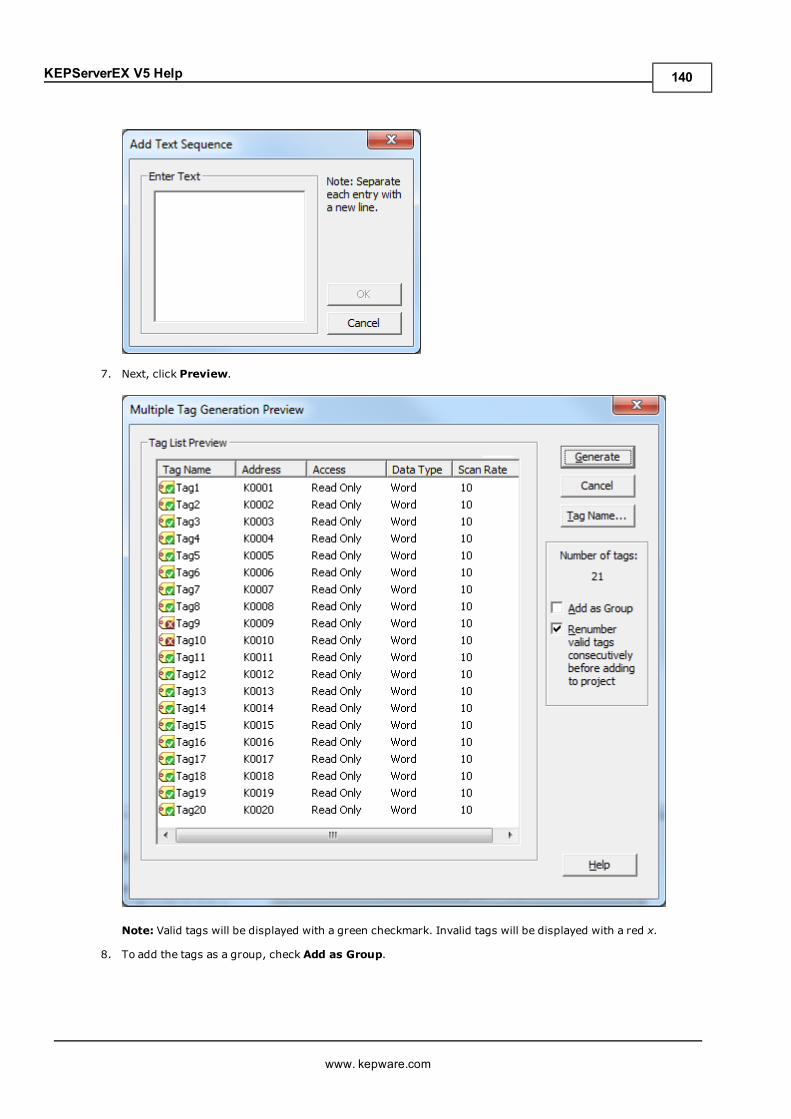
KEPServerEX V5 Help
7. Next, click Preview.
Note: Valid tags will be displayed with a green checkmark. Invalid tags will be displayed with a red x.
8. To add the tags as a group, check Add as Group.
www. kepware.com
140
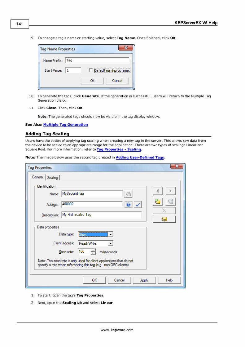
KEPServerEX V5 Help
9. To change a tag's name or starting value, select Tag Name. Once finished, clickOK.
10. To generate the tags, click Generate. If the generation is successful, users will return to the Multiple TagGeneration dialog.
11. Click Close. Then, clickOK.
Note: The generated tags should now be visible in the tag display window.
See Also: Multiple Tag Generation
Adding Tag ScalingUsers have the option of applying tag scaling when creating a new tag in the server. This allows raw data fromthe device to be scaled to an appropriate range for the application. There are two types of scaling: Linear andSquare Root. For more information, refer to Tag Properties - Scaling.
Note: The image below uses the second tag created in Adding User-Defined Tags.
1. To start, open the tag's Tag Properties.
2. Next, open the Scaling tab and select Linear.
www. kepware.com
141
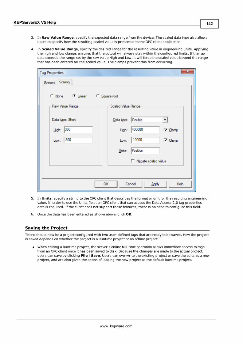
KEPServerEX V5 Help
3. In Raw Value Range, specify the expected data range from the device. The scaled data type also allowsusers to specify how the resulting scaled value is presented to the OPC client application.
4. In Scaled Value Range, specify the desired range for the resulting value in engineering units. Applyingthe high and low clamps ensures that the output will always stay within the configured limits. If the rawdata exceeds the range set by the raw value High and Low, it will force the scaled value beyond the rangethat has been entered for the scaled value. The clamps prevent this from occurring.
5. In Units, specify a string to the OPC client that describes the format or unit for the resulting engineeringvalue. In order to use the Units field, an OPC client that can access the Data Access 2.0 tag propertiesdata is required. If the client does not support these features, there is no need to configure this field.
6. Once the data has been entered as shown above, clickOK.
Saving the ProjectThere should now be a project configured with two user-defined tags that are ready to be saved. How the projectis saved depends on whether the project is a Runtime project or an offline project.
l When editing a Runtime project, the server's online full-time operation allows immediate access to tagsfrom an OPC client once it has been saved to disk. Because the changes are made to the actual project,users can save by clicking File | Save. Users can overwrite the existing project or save the edits as a newproject, and are also given the option of loading the new project as the default Runtime project.
www. kepware.com
142
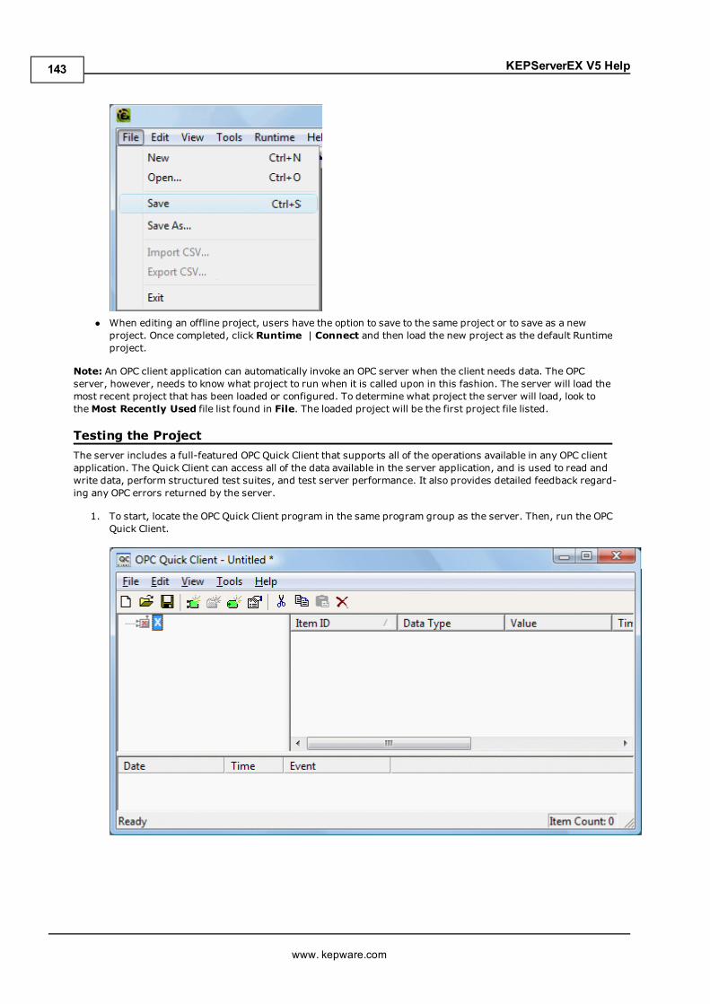
KEPServerEX V5 Help
l When editing an offline project, users have the option to save to the same project or to save as a newproject. Once completed, click Runtime | Connect and then load the new project as the default Runtimeproject.
Note: An OPC client application can automatically invoke an OPC server when the client needs data. The OPCserver, however, needs to know what project to run when it is called upon in this fashion. The server will load themost recent project that has been loaded or configured. To determine what project the server will load, look totheMost Recently Used file list found in File. The loaded project will be the first project file listed.
Testing the ProjectThe server includes a full-featured OPC Quick Client that supports all of the operations available in any OPC clientapplication. The Quick Client can access all of the data available in the server application, and is used to read andwrite data, perform structured test suites, and test server performance. It also provides detailed feedback regard-ing any OPC errors returned by the server.
1. To start, locate the OPC Quick Client program in the same program group as the server. Then, run the OPCQuick Client.
www. kepware.com
143
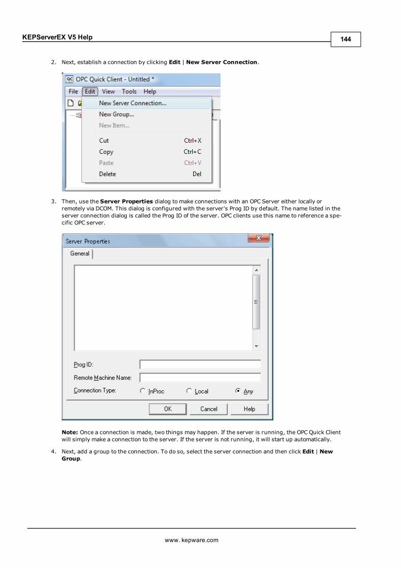
KEPServerEX V5 Help
2. Next, establish a connection by clicking Edit | New Server Connection.
3. Then, use the Server Properties dialog to make connections with an OPC Server either locally orremotely via DCOM. This dialog is configured with the server's Prog ID by default. The name listed in theserver connection dialog is called the Prog ID of the server. OPC clients use this name to reference a spe-cific OPC server.
Note: Once a connection is made, two things may happen. If the server is running, the OPC Quick Clientwill simply make a connection to the server. If the server is not running, it will start up automatically.
4. Next, add a group to the connection. To do so, select the server connection and then click Edit | NewGroup.
www. kepware.com
144
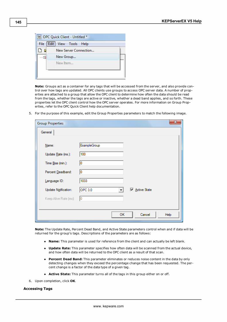
KEPServerEX V5 Help
Note: Groups act as a container for any tags that will be accessed from the server, and also provide con-trol over how tags are updated. All OPC clients use groups to access OPC server data. A number of prop-erties are attached to a group that allow the OPC client to determine how often the data should be readfrom the tags, whether the tags are active or inactive, whether a dead band applies, and so forth. Theseproperties let the OPC client control how the OPC server operates. For more information on Group Prop-erties, refer to the OPC Quick Client help documentation.
5. For the purpose of this example, edit the Group Properties parameters to match the following image.
Note: The Update Rate, Percent Dead Band, and Active State parameters control when and if data will bereturned for the group's tags. Descriptions of the parameters are as follows:
l Name: This parameter is used for reference from the client and can actually be left blank.
l Update Rate: This parameter specifies how often data will be scanned from the actual device,and how often data will be returned to the OPC client as a result of that scan.
l Percent Dead Band: This parameter eliminates or reduces noise content in the data by onlydetecting changes when they exceed the percentage change that has been requested. The per-cent change is a factor of the data type of a given tag.
l Active State: This parameter turns all of the tags in this group either on or off.
6. Upon completion, clickOK.
Accessing Tags
www. kepware.com
145
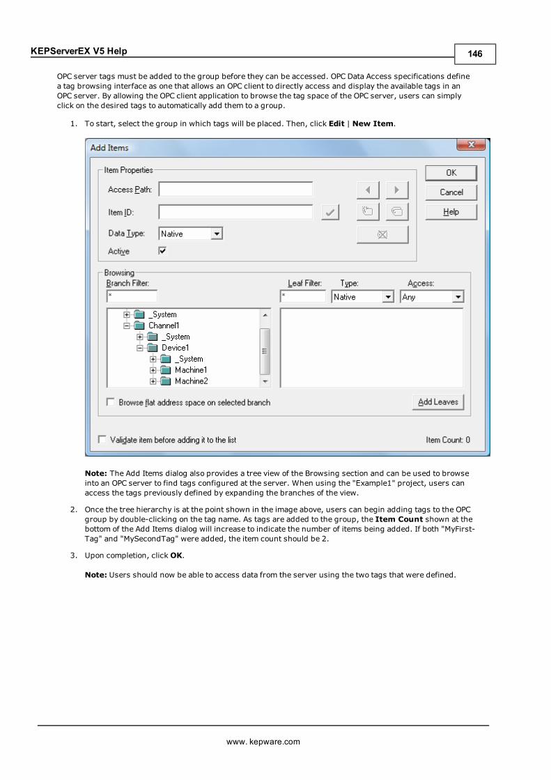
KEPServerEX V5 Help
OPC server tags must be added to the group before they can be accessed. OPC Data Access specifications definea tag browsing interface as one that allows an OPC client to directly access and display the available tags in anOPC server. By allowing the OPC client application to browse the tag space of the OPC server, users can simplyclick on the desired tags to automatically add them to a group.
1. To start, select the group in which tags will be placed. Then, click Edit | New Item.
Note: The Add Items dialog also provides a tree view of the Browsing section and can be used to browseinto an OPC server to find tags configured at the server. When using the "Example1" project, users canaccess the tags previously defined by expanding the branches of the view.
2. Once the tree hierarchy is at the point shown in the image above, users can begin adding tags to the OPCgroup by double-clicking on the tag name. As tags are added to the group, the Item Count shown at thebottom of the Add Items dialog will increase to indicate the number of items being added. If both "MyFirst-Tag" and "MySecondTag" were added, the item count should be 2.
3. Upon completion, clickOK.
Note: Users should now be able to access data from the server using the two tags that were defined.
www. kepware.com
146
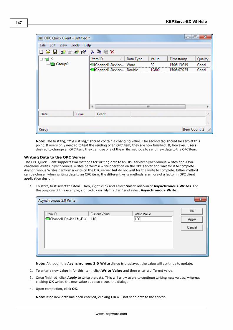
KEPServerEX V5 Help
Note: The first tag, "MyFirstTag," should contain a changing value. The second tag should be zero at thispoint. If users only needed to test the reading of an OPC item, they are now finished. If, however, usersdesired to change an OPC item, they can use one of the write methods to send new data to the OPC item.
Writing Data to the OPC ServerThe OPC Quick Client supports twomethods for writing data to an OPC server: Synchronous Writes and Asyn-chronous Writes. Synchronous Writes perform a write operation on the OPC server and wait for it to complete.Asynchronous Writes perform a write on the OPC server but do not wait for the write to complete. Either methodcan be chosen when writing data to an OPC item: the different write methods are more of a factor in OPC clientapplication design.
1. To start, first select the item. Then, right-click and select Synchronous or Asynchronous Writes. Forthe purpose of this example, right-click on "MyFirstTag" and select Asynchronous Write.
Note: Although the Asynchronous 2.0 Write dialog is displayed, the value will continue to update.
2. To enter a new value in for this item, clickWrite Value and then enter a different value.
3. Once finished, click Apply to write the data. This will allow users to continue writing new values, whereasclicking OK writes the new value but also closes the dialog.
4. Upon completion, clickOK.
Note: If no new data has been entered, clicking OK will not send data to the server.
www. kepware.com
147
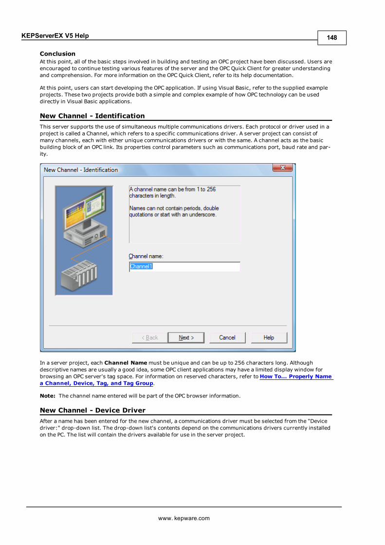
KEPServerEX V5 Help
ConclusionAt this point, all of the basic steps involved in building and testing an OPC project have been discussed. Users areencouraged to continue testing various features of the server and the OPC Quick Client for greater understandingand comprehension. For more information on the OPC Quick Client, refer to its help documentation.
At this point, users can start developing the OPC application. If using Visual Basic, refer to the supplied exampleprojects. These two projects provide both a simple and complex example of how OPC technology can be useddirectly in Visual Basic applications.
New Channel - IdentificationThis server supports the use of simultaneous multiple communications drivers. Each protocol or driver used in aproject is called a Channel, which refers to a specific communications driver. A server project can consist ofmany channels, each with either unique communications drivers or with the same. A channel acts as the basicbuilding block of an OPC link. Its properties control parameters such as communications port, baud rate and par-ity.
In a server project, each Channel Namemust be unique and can be up to 256 characters long. Althoughdescriptive names are usually a good idea, some OPC client applications may have a limited display window forbrowsing an OPC server's tag space. For information on reserved characters, refer toHow To... Properly Namea Channel, Device, Tag, and Tag Group.
Note: The channel name entered will be part of the OPC browser information.
New Channel - Device DriverAfter a name has been entered for the new channel, a communications driver must be selected from the "Devicedriver:" drop-down list. The drop-down list's contents depend on the communications drivers currently installedon the PC. The list will contain the drivers available for use in the server project.
www. kepware.com
148
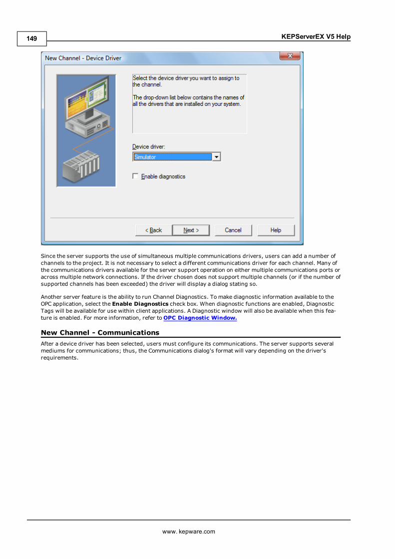
KEPServerEX V5 Help
Since the server supports the use of simultaneous multiple communications drivers, users can add a number ofchannels to the project. It is not necessary to select a different communications driver for each channel. Many ofthe communications drivers available for the server support operation on either multiple communications ports oracross multiple network connections. If the driver chosen does not support multiple channels (or if the number ofsupported channels has been exceeded) the driver will display a dialog stating so.
Another server feature is the ability to run Channel Diagnostics. To make diagnostic information available to theOPC application, select the Enable Diagnostics check box. When diagnostic functions are enabled, DiagnosticTags will be available for use within client applications. A Diagnostic window will also be available when this fea-ture is enabled. For more information, refer toOPC Diagnostic Window.
New Channel - CommunicationsAfter a device driver has been selected, users must configure its communications. The server supports severalmediums for communications; thus, the Communications dialog's format will vary depending on the driver'srequirements.
www. kepware.com
149
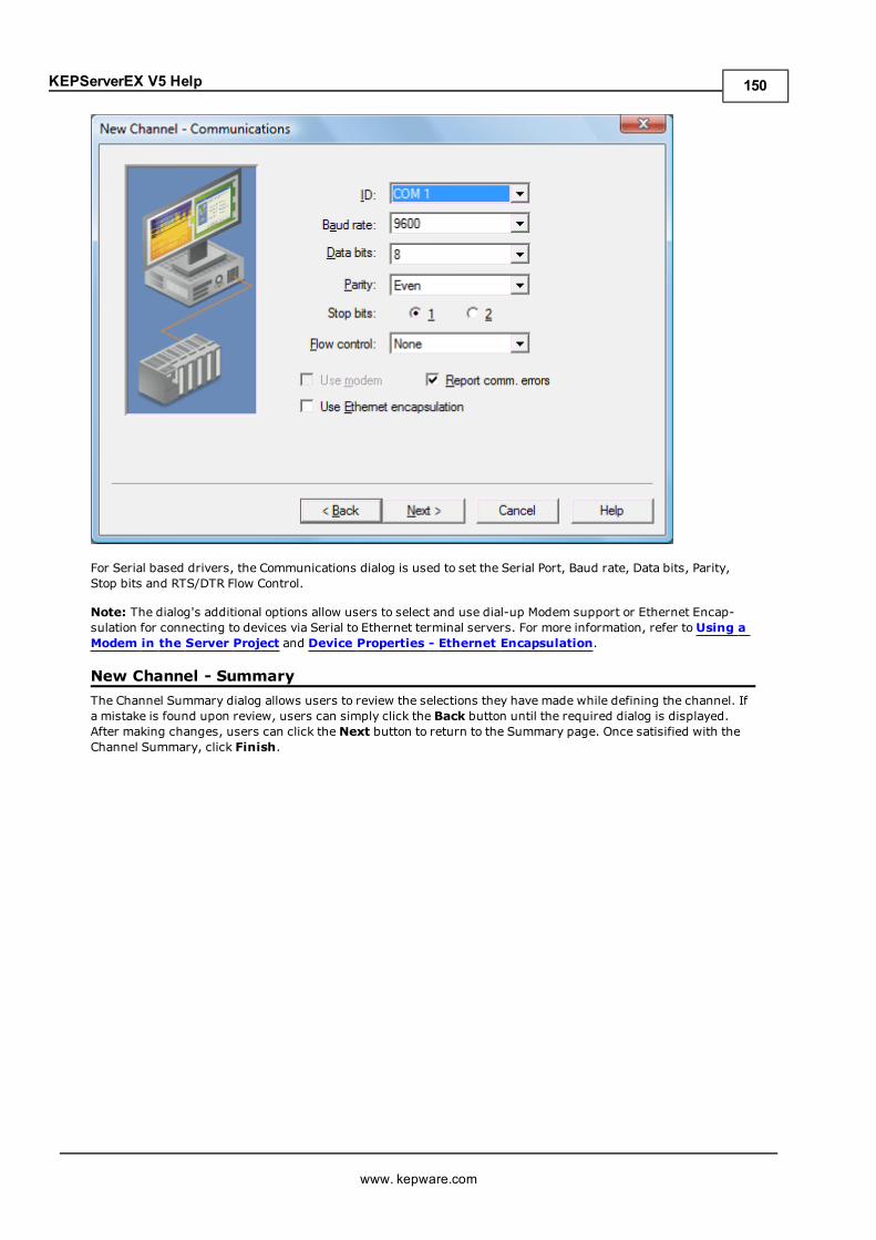
KEPServerEX V5 Help
For Serial based drivers, the Communications dialog is used to set the Serial Port, Baud rate, Data bits, Parity,Stop bits and RTS/DTR Flow Control.
Note: The dialog's additional options allow users to select and use dial-up Modem support or Ethernet Encap-sulation for connecting to devices via Serial to Ethernet terminal servers. For more information, refer toUsing aModem in the Server Project and Device Properties - Ethernet Encapsulation.
New Channel - SummaryThe Channel Summary dialog allows users to review the selections they have made while defining the channel. Ifa mistake is found upon review, users can simply click the Back button until the required dialog is displayed.After making changes, users can click theNext button to return to the Summary page. Once satisified with theChannel Summary, click Finish.
www. kepware.com
150
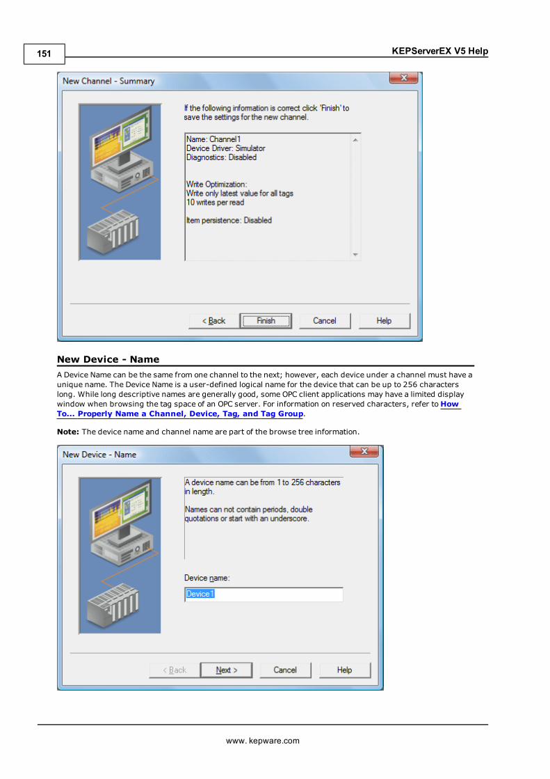
KEPServerEX V5 Help
New Device - NameA Device Name can be the same from one channel to the next; however, each device under a channel must have aunique name. The Device Name is a user-defined logical name for the device that can be up to 256 characterslong. While long descriptive names are generally good, some OPC client applications may have a limited displaywindow when browsing the tag space of an OPC server. For information on reserved characters, refer toHowTo... Properly Name a Channel, Device, Tag, and Tag Group.
Note: The device name and channel name are part of the browse tree information.
www. kepware.com
151
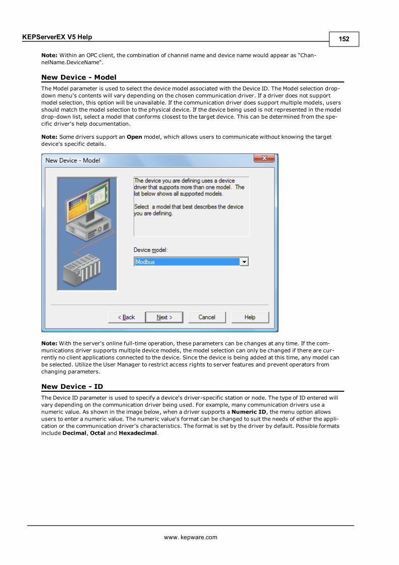
KEPServerEX V5 Help
Note: Within an OPC client, the combination of channel name and device name would appear as "Chan-nelName.DeviceName".
New Device - ModelThe Model parameter is used to select the device model associated with the Device ID. The Model selection drop-down menu's contents will vary depending on the chosen communication driver. If a driver does not supportmodel selection, this option will be unavailable. If the communication driver does support multiple models, usersshould match the model selection to the physical device. If the device being used is not represented in the modeldrop-down list, select a model that conforms closest to the target device. This can be determined from the spe-cific driver's help documentation.
Note: Some drivers support an Open model, which allows users to communicate without knowing the targetdevice's specific details.
Note:With the server's online full-time operation, these parameters can be changes at any time. If the com-munications driver supports multiple device models, the model selection can only be changed if there are cur-rently no client applications connected to the device. Since the device is being added at this time, any model canbe selected. Utilize the User Manager to restrict access rights to server features and prevent operators fromchanging parameters.
New Device - IDThe Device ID parameter is used to specify a device's driver-specific station or node. The type of ID entered willvary depending on the communication driver being used. For example, many communication drivers use anumeric value. As shown in the image below, when a driver supports aNumeric ID, the menu option allowsusers to enter a numeric value. The numeric value's format can be changed to suit the needs of either the appli-cation or the communication driver's characteristics. The format is set by the driver by default. Possible formatsincludeDecimal, Octal and Hexadecimal.
www. kepware.com
152
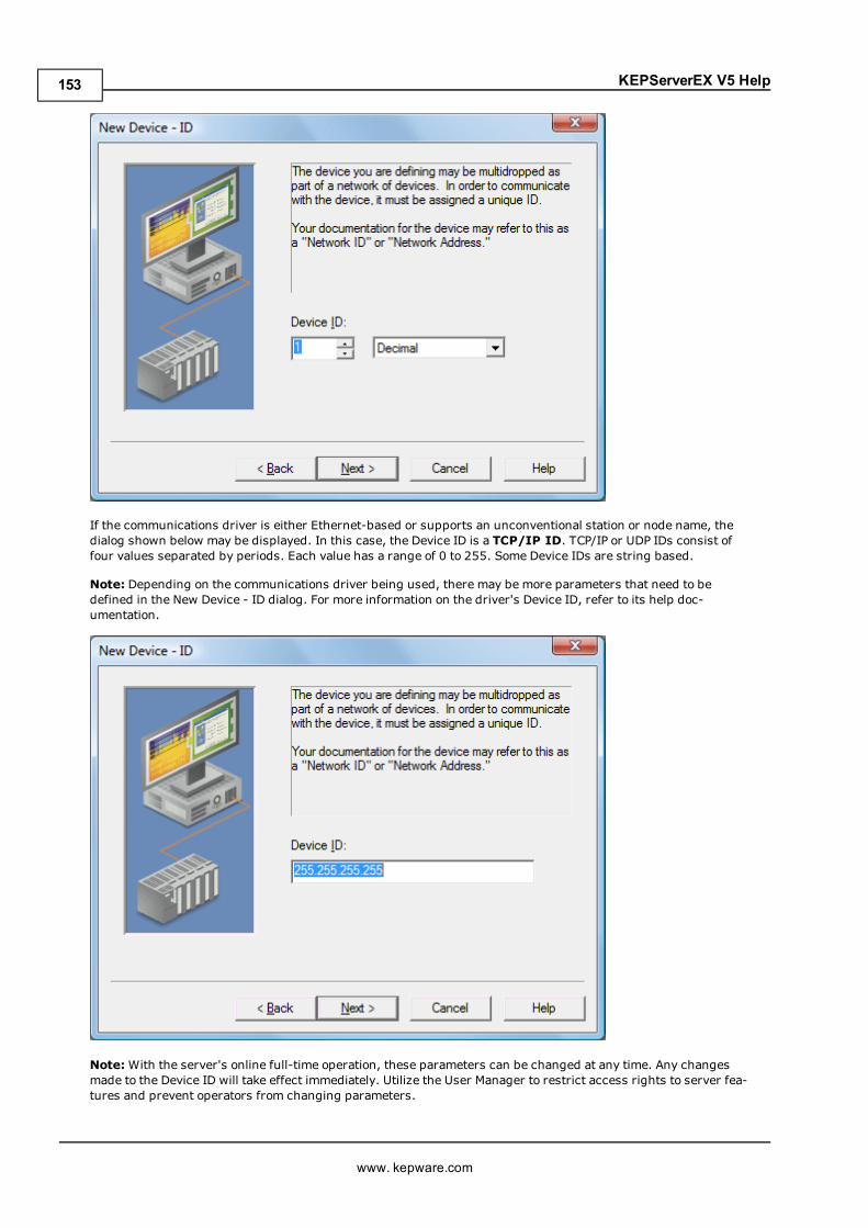
KEPServerEX V5 Help
If the communications driver is either Ethernet-based or supports an unconventional station or node name, thedialog shown below may be displayed. In this case, the Device ID is a TCP/IP ID. TCP/IP or UDP IDs consist offour values separated by periods. Each value has a range of 0 to 255. Some Device IDs are string based.
Note: Depending on the communications driver being used, there may be more parameters that need to bedefined in the New Device - ID dialog. For more information on the driver's Device ID, refer to its help doc-umentation.
Note:With the server's online full-time operation, these parameters can be changed at any time. Any changesmade to the Device ID will take effect immediately. Utilize the User Manager to restrict access rights to server fea-tures and prevent operators from changing parameters.
www. kepware.com
153
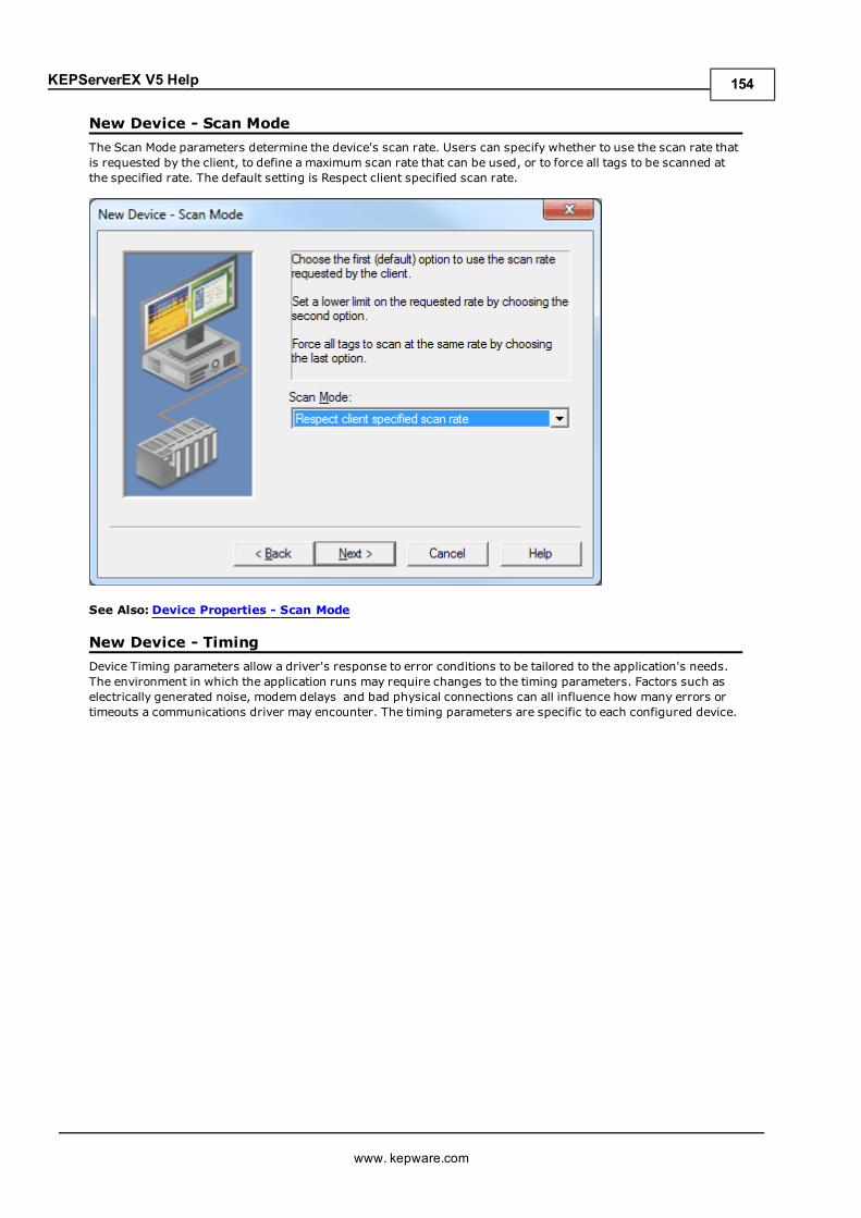
KEPServerEX V5 Help
New Device - Scan ModeThe Scan Mode parameters determine the device's scan rate. Users can specify whether to use the scan rate thatis requested by the client, to define a maximum scan rate that can be used, or to force all tags to be scanned atthe specified rate. The default setting is Respect client specified scan rate.
See Also: Device Properties - Scan Mode
New Device - TimingDevice Timing parameters allow a driver's response to error conditions to be tailored to the application's needs.The environment in which the application runs may require changes to the timing parameters. Factors such aselectrically generated noise, modem delays and bad physical connections can all influence how many errors ortimeouts a communications driver may encounter. The timing parameters are specific to each configured device.
www. kepware.com
154
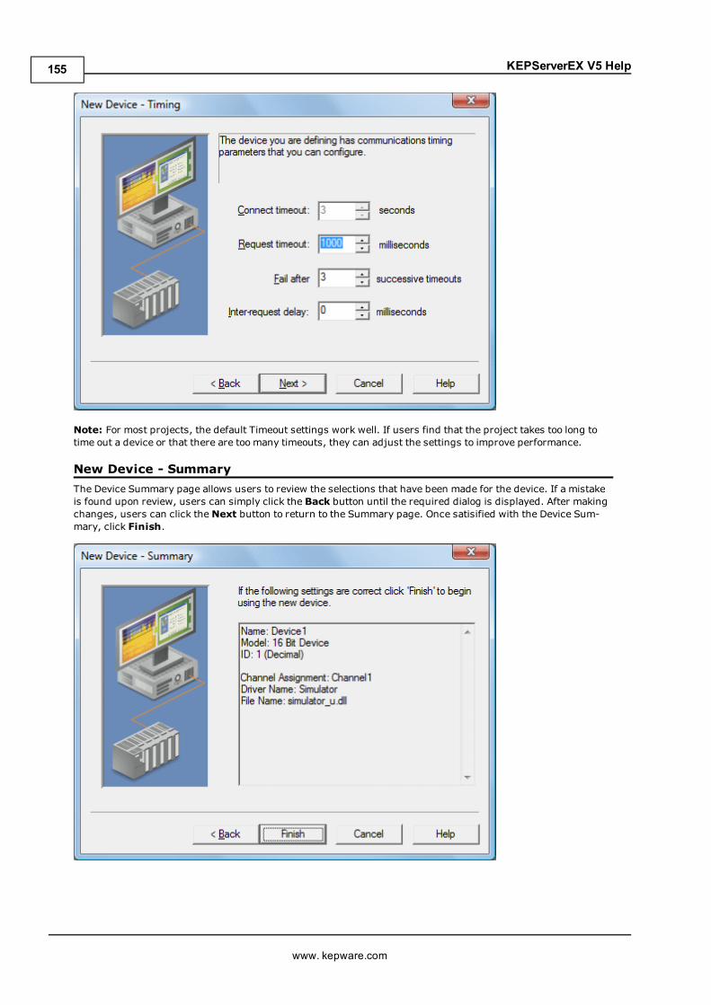
KEPServerEX V5 Help
Note: For most projects, the default Timeout settings work well. If users find that the project takes too long totime out a device or that there are too many timeouts, they can adjust the settings to improve performance.
New Device - SummaryThe Device Summary page allows users to review the selections that have been made for the device. If a mistakeis found upon review, users can simply click the Back button until the required dialog is displayed. After makingchanges, users can click theNext button to return to the Summary page. Once satisified with the Device Sum-mary, click Finish.
www. kepware.com
155
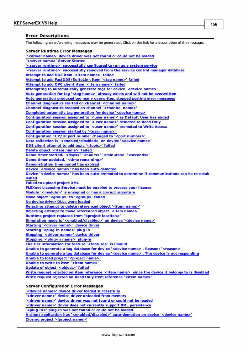
KEPServerEX V5 Help
Error DescriptionsThe following error/warning messages may be generated. Click on the link for a description of the message.
Server Runtime Error Messages'<driver name>' device driver was not found or could not be loaded'<server name>' Server Started'<server runtime>' successfully configured to run as a system service'<server runtime>' successfully removed from the service control manager databaseAttempt to add DDE item '<item name>' failedAttempt to add FastDDE/SuiteLink item '<tag name>' failedAttempt to add OPC client item '<item name>' failedAttempting to automatically generate tags for device '<device name>'Auto generation for tag '<tag name>' already exists and will not be overwrittenAuto generation produced too many overwrites, stopped posting error messagesChannel diagnostics started on channel '<channel name>'Channel diagnostics stopped on channel '<channel name>'Completed automatic tag generation for device '<device name>'Configuration session assigned to '<user name>' as Default User has endedConfiguration session assigned to '<user name>' demoted to Read OnlyConfiguration session assigned to '<user name>' promoted to Write AccessConfiguration session started by '<user name>'Configuration TCP/IP port number changed to '<port number>'Data collection is '<enabled/disabled>' on device '<device name>'DDE client attempt to add topic '<topic>' failedDelete object '<item name>' failedDemo timer started. '<days>' '<hours>' '<minutes>' '<seconds>'Demo timer updated. '<time remaining>'Demonstration time period has expiredDevice '<device name>' has been auto-demotedDevice '<device name>' has been auto-promoted to determine if communications can be re-estab-lishedFailed to upload project XMLFLEXnet Licensing Service must be enabled to process your licenseModule '<module>' is unsigned or has a corrupt signatureMove object '<group>' to '<group>' failedNo device driver DLLs were loadedRejecting attempt to delete referenced object '<item name>'Rejecting attempt to move referenced object '<item name>'Runtime project replaced from '<project location>'Simulation mode is '<enabled/disabled>' on device '<device name>'Starting '<driver name>' device driverStarting '<plug-in name>' plug-inStopping '<driver name>' device driverStopping '<plug-in name>' plug-inThe tier information for feature '<feature>' is invalidUnable to generate a tag database for device '<device name>'. Reason: '<reason>'Unable to generate a tag database for device '<device name>'. The device is not respondingUnable to load project '<project name>'Unable to write to item '<item name>'Update of object '<object>' failedWrite request rejected on item reference '<item name>' since the device it belongs to is disabledWrite request rejected on Read Only item reference '<item name>'
Server Configuration Error Messages'<device name>' device driver loaded successfully'<driver name>' device driver unloaded from memory'<driver name>' device driver was not found or could not be loaded'<driver name>' driver does not currently support XML persistence'<plug-in>' plug-in was not found or could not be loadedA client application has '<enabled/disabled>' auto-demotion on device '<device name>'Closing project '<project name>'
www. kepware.com
156
KEPServerEX V5 Help
Created backup of project '<project name>' to '<file location>'Duplicate Channel Wizard page ID '<ID number>' detectedError importing CSV tag record '<record number>': '<tag name>' is not a valid tag group nameError importing CSV tag record '<record number>': '<tag name>' is not a valid tag nameError importing CSV tag record '<record number>': Missing addressError importing CSV tag record '<record number>': Tag or group name exceeds 256 charactersFailed to reset channel diagnosticsFailed to retrieve Runtime projectInvalid Ethernet encapsulation IP '<IP address>'Invalid or missing Modem Configuration on channel '<channel name', substituting '<modem>'Invalid XML document '<XML name>'Maximum channel count exceeded for the lite version '<driver name>' driver licenseMaximum device count exceeded for the lite version '<driver name>' driver licenseMaximum Runtime tag count exceeded for the lite version '<driver name>' driver licenseModem initialization failed on channel '<channel name>'Opening project '<project name>'Required schema file '<schema name>' not foundRuntime project update failedStarting OPC diagnosticsStopping OPC diagnosticsUnable to add channel due to driver-level failureUnable to add device due to driver-level failureUnable to backup project file to '<file name/location>'Unable to backup project file to '<file path>'Unable to begin device discovery on channel '<Channel Name>'Unable to launch OPC Quick Client [Path: '<path>' OS Error: '<error>']Unable to load driver DLL '<driver name>'Unable to load the '<driver name>' driver because more than one copy exists ('<driver name>' and'<driver name>'Unable to use network adapter '<adapter>' on channel '<channel name>'. Using default networkadapterValidation error on '<tag name>': Invalid scaling parameters
General Operation System Error Messages, Error control, Forced error control, Hardware flow control, Software flow controlDialing '<phone number>' on line '<modem name>'Dialing aborted on '<modem name>'Dialing on line '<modem name>' cancelled by userFailed to open modem line '<modem name>' [TAPI error]Hardware error on line '<modem name>'Incoming call detected on line '<modem name>'Line '<modem name>' connectedLine '<modem name>' connected at '<baud rate>' baudLine '<modem name>' disconnectedLine '<modem name>' is already in useLine dropped at remote site on '<modem name>'Modem line closed: '<modem name>'Modem line opened: '<modem name>'Modem to Modem DCE: '<connection parameters>'MODEMSETTINGS unavailableNo comm handle provided on connect for line '<modem name>'No dial tone on '<modem name>'Remote line is busy on '<modem name>'Remote line is not answering on '<modem name>'TAPI configuration has changed, reinitializing...TAPI line initialization failed: '<modem name>'The phone number is invalid '<phone number>'Unable to apply Modem Configuration on line '<modem name>'Unable to dial on line '<modem name>'
www. kepware.com
157
KEPServerEX V5 Help
Unable to start Net DDE
iFIX Error MessagesAttempt to add iFIX PDB item '< item name>' failedFailed to enable iFIX PDB support for this server [OS Error = n]Unable to enable iFIX PDB support for this serverUnable to read '<tag name>' on device '<channel name/device name>'
Server Runtime Error MessagesThe following error/warning messages may be generated. Click on the link for a description of the message.
Server Runtime Error Messages'<driver name>' device driver was not found or could not be loaded'<server name>' Server Started'<server runtime>' successfully configured to run as a system service'<server runtime>' successfully removed from the service control manager databaseAttempt to add DDE item '<item name>' failedAttempt to add FastDDE/SuiteLink item '<tag name>' failedAttempt to add OPC client item '<item name>' failedAttempting to automatically generate tags for device '<device name>'Auto generation for tag '<tag name>' already exists and will not be overwrittenAuto generation produced too many overwrites, stopped posting error messagesChannel diagnostics started on channel '<channel name>'Channel diagnostics stopped on channel '<channel name>'Completed automatic tag generation for device '<device name>'Configuration session assigned to '<user name>' as Default User has endedConfiguration session assigned to '<user name>' demoted to Read OnlyConfiguration session assigned to '<user name>' promoted to Write AccessConfiguration session started by '<user name>'Configuration TCP/IP port number changed to '<port number>'Data collection is '<enabled/disabled>' on device '<device name>'DDE client attempt to add topic '<topic>' failedDelete object '<item name>' failedDemo timer started. '<days>' '<hours>' '<minutes>' '<seconds>'Demo timer updated. '<time remaining>'Demonstration time period has expiredDevice '<device name>' has been auto-demotedDevice '<device name>' has been auto-promoted to determine if communications can be re-estab-lishedFailed to upload project XMLFLEXnet Licensing Service must be enabled to process your licenseModule '<module>' is unsigned or has a corrupt signatureMove object '<group>' to '<group>' failedNo device driver DLLs were loadedRejecting attempt to delete referenced object '<item name>'Rejecting attempt to move referenced object '<item name>'Runtime project replaced from '<project location>'Simulation mode is '<enabled/disabled>' on device '<device name>'Starting '<driver name>' device driverStarting '<plug-in name>' plug-inStopping '<driver name>' device driverStopping '<plug-in name>' plug-inThe tier information for feature '<feature>' is invalidUnable to generate a tag database for device '<device name>'. Reason: '<reason>'Unable to generate a tag database for device '<device name>'. The device is not respondingUnable to load project '<project name>'Unable to write to item '<item name>'Update of object '<object>' failedWrite request rejected on item reference '<item name>' since the device it belongs to is disabledWrite request rejected on Read Only item reference '<item name>'
www. kepware.com
158
KEPServerEX V5 Help
'<driver name>' device driver was not found or could not be loadedError Type:Warning
Possible Cause:A project using a driver that has not been installed or that is not compatible with the current server/driver ver-sion was started but could not properly launch.
Solution:1. If the driver is not installed, re-run the install and select the driver.2. If the driver is installed, verify the version that the project was created with and install a compatible version onthe running PC.
Note:Every attempt is made to ensure backwards compatibility in the server so that projects created in older versionsmay be loaded in newer versions. However, since new versions of the server and driver may have properties andconfigurations that do not exist in older version, users may not be able to open or load a project created in anewer version of the server in an older version.
'<server name>' Server StartedError Type:Informational
Source:Runtime
Possible Cause:The server Runtime has started successfully.
Solution:N/A.
'<server runtime>' successfully configured to run as a system serviceError Type:Informational
Possible Cause:The server runtime process has been switched from "Interactive" to "System service" mode.
Solution:None.
'<server runtime>' successfully removed from the service control managerdatabaseError Type:Informational
Possible Cause:The server runtime process has been switched from "System Service" to "Interactive" mode.
Solution:None.
Attempt to add DDE item '<item name>' failedError Type:Error
Source:Runtime
www. kepware.com
159
KEPServerEX V5 Help
Possible Cause:An attempt to add an item from a DDE client failed.
Solution:1. If attempting to add an item dynamically to a tag group that is not supported in the server: Add Dynamic Tagsto the device level only.2. If attempting to add an item dynamically but used the incorrect address syntax: Verify the syntax and tryagain.3. If attempting to add an item that was not created as a static tag in the server: Add the tag in the server andthen try adding the item from the client.4. If attempting to add an item but used incorrect syntax: Correct the syntax and try again.
Attempt to add FastDDE/SuiteLink item '<tag name>' failedError Type:Error
Source:Runtime
Possible Cause:1. The user attempted to add an item from a FastDDE/Suitelink client that was not a static tag in the server.2. The user attempted to add an item from a FastDDE/Suitelink client that had incorrect syntax.
Solution:1. Check the item syntax and correct if necessary.2. Verify that the item is a valid address in the driver. If not, either use the correct address or remove therequest.3. Verify that the static tag exists in the project. If not, either add it or remove the request.
Attempt to add OPC Client item '<item name>' failedError Type:Error
Source:Runtime
Possible Cause:An attempt to add an item from an OPC client failed.
Solution:1. If attempting to add an item dynamically to a tag group that is not supported in the server: Add Dynamic Tagsto the device level only.2. If attempting to add an item dynamically but used the incorrect address syntax: Verify the syntax and tryagain.3. If attempting to add an item that was not created as a static tag in the server: Add the tag in the server andthen try adding the item from the client.4. If attempting to add an item but used incorrect syntax: Correct the syntax and try again.
Attempting to automatically generate tags for device '<device name>'Error Type:Informational
Source:Runtime
Possible Cause:The server is attempting to generate tags for the specified device.
Solution:N/A.
www. kepware.com
160
KEPServerEX V5 Help
Auto generation for tag '<tag name>' already exists and will not be over-writtenError Type:Warning
Source:Runtime
Possible Cause:Although the server is regenerating tags for the tag database, it has been set not to overwrite tags that alreadyexist.
Solution:If this is not the desired action, change the setting in the Database Creation Properties dialog.
Auto generation produced too many overwrites, stopped posting error mes-sagesError Type:Warning
Source:Runtime
Possible Cause:To keep from filling the error log, the server has stopped posting error messages on tags that cannot be over-written during automatic tag generation.
Solution:N/A.
Channel diagnostics started on channel '<channel name>'Error Type:Informational
Source:Runtime
Possible Cause:Channel diagnostics have started successfully on the channel.
Solution:N/A.
Channel diagnostics stopped on channel '<channel name>'Error Type:Informational
Source:Runtime
Possible Cause:Channel diagnostics have stopped successfully on the channel.
Solution:N/A.
Completed automatic tag generation for device '<device name>'Error Type:Informational
www. kepware.com
161
KEPServerEX V5 Help
Source:Runtime
Possible Cause:The server successfully generated tags for the tag database.
Solution:N/A.
Configuration session assigned to '<user name>' as Default User has endedError Type:Warning
Source:Runtime
Possible Cause:The specified user connected to the Runtime has ended the session.
Solution:None.
Configuration session assigned to '<user name>' demoted to Read OnlyError Type:Informational
Source:Runtime
Possible Cause:The connected user has been idle for more than 15 minutes, and so the server automatically demoted them.
Solution:When connected with the Configuration, do not leave the connection idle if in write access mode.
Configuration session assigned to '<user name>' promoted to Write AccessError Type:Informational
Source:Runtime
Possible Cause:A user that was connected to the Runtime with Write Access has disconnected or demoted due to being idle.
Solution:N/A.
Configuration session started by '<user name>'Error Type:Warning
Source:Runtime
Possible Cause:A user on the local or remote PC has started a configuration session using a user login with Read/Write access tothe Runtime project.
Solution:
www. kepware.com
162
KEPServerEX V5 Help
The first user to connect to the Runtime with a Configuration will have Read/Write access to the Runtime all otherusers to connect will have Read Only access.
Configuration TCP/IP port number changed to '<port number>'Error Type:Informational
Source:Runtime
Possible Cause:The port number that is used to connect the Configuration to the Runtime has been changed.
Solution:The port was changed in the Administration settings. Change the port number in the Configuration Options in theRuntime Connection Options to match the new Runtime port.
Data collection is '<enabled/disabled>' on device '<device name>'Error Type:Informational
Source:Runtime
Possible Cause:1. A client application has programmatically Enabled/Disabled Data Collection for the specified device.2. The user's Configuration has Enabled/Disabled Data Collection for the specified device.
Solution:N/A.
DDE client attempt to add topic '<topic>' failedError Type:Error
Source:Runtime
Possible Cause:An attempt was made by a DDE client to add or reference a topic that does not exist.
Solution:1. Verify that an alias has been created in the alias map with the same name as the topic.2. The global topic is '_ddeData.' If using it, make sure to use the correct syntax. It is not case sensitive.
Delete object '<item name>' failedError Type:Warning
Source:Runtime
Possible Cause:An attempt to remove an object failed.
Solution:Reference the item by something else. The user may not have privileges to remove the object.
Demo timer started. '<days>' '<hours>' '<minutes>' '<seconds>'Error Type:
www. kepware.com
163
KEPServerEX V5 Help
Warning
Source:Runtime
Possible Cause:The server has started in demomode with the specified time remaining in the demo period.
Solution:1. If evaluating the server, no action needs to be taken.2. If this is a production machine, activate the product licenses for the installed components before the demotime period expires.
Demo timer updated. '<time remaining>'Error Type:Warning
Possible Cause:None.
Solution:None.
Demonstration time period has expired for <Feature Name>Error Type:Warning
Source:Runtime
Possible Cause:The server was running in demomode, but the demo period has expired.
Solution:1. Obtain a license for the drivers or plug-ins that were functioning as a demo. For more information, refer to"Support Information," which may be accessed either from the server's Help menu or from the server's Admin-istration menu (located in the System Tray).2. Reset the two-hour demo period by stopping and restarting the server Runtime. To do so, select "Stop RuntimeService" and then "Start Runtime Service" from the server's Administration menu.
Notes:1. For information on managing licenses, refer to the License Utility help file.2. Often, an unlicensed (demo) driver or plug-in is temporarily activated either prior to or after a project is loadedwith licensed drivers or plug-ins. This will trigger the two-hour demo period, which will stop the server Runtimeproject once it expires. To properly restart a licensed project without triggering the demo period, load a projectwhich only uses licensed drivers and plug-ins. Then, stop and the start the server Runtime from the Admin-istration menu.
Device '<device name>' has been auto-demotedError Type:Warning
Source:Runtime
Possible Cause:Communications with the specified device have failed. The device has been demoted from the poll cycle.
Solution:1. If the device fails to reconnect, investigate the reasons behind the communications loss and then correct it.2. To stop the device from being demoted, diasbled Auto-Demotion.
www. kepware.com
164
KEPServerEX V5 Help
Device '<device name>' has been auto-promoted to determine if com-munications can be re-establishedError Type:Informational
Source:Runtime
Possible Cause:If a device that was previously demoted from the poll cycle has been promoted, check to see if it is now available.
Solution:N/A.
Notes:If communications fail, the device will be demoted again.
Failed to upload project XMLError Type:Error
Source:Runtime
Possible Cause:1. The driver, driver schema file or both are not installed.2. The project was saved in a newer version of the server or one that has incompatible schema fields.
Solution:1. Verify that the driver and schema files are installed.2. Compare the versions of the server in which the file was created against the version in which it is being loaded.
FLEXnet Licensing Service must be enabled to process your license. Runtimereferences are limited to demo operationError Type:Warning
Source:Runtime
Possible Cause:The user is attempting to license a driver or component without the Runtime enabled and running.
Solution:Start the Runtime Service and then re-attempt licensing.
Module '<module>' is unsigned or has a corrupt signature. Runtime referencesare limited to demo operationError Type:Warning
Source:Runtime
Possible Cause:Runtime attempted to validate a license certificate and failed.
Solution:1. Ensure that the license subscriptions are updated.2. Ensure that the drivers or suites being used are properly licensed.
www. kepware.com
165
KEPServerEX V5 Help
Note:Until the problem is corrected, the Runtime project will run in Demomode.
Move object '<group>' to '<group>' failedError Type:Warning
Source:Runtime
Possible Cause:An attempt to move a tag or group to another group or device failed because the item is referenced by anotherobject.
Solution:The object may be referenced by another object, although the user may not have the privileges to make thechange.
No device driver DLLs were loadedError Type:Error
Source:Runtime
Possible Cause:The drivers may not have been installed or updated when the server was installed.
Solution:1. Drivers are synchronized with the server build. Drivers from previous builds may not have required changes;therefore, they cannot be loaded when the server starts. Re-run the server install.2. The drivers folder is empty; therefore, no drivers could be loaded. Re-run the server install.
Rejecting attempt to delete referenced object '<item name>'Error Type:Warning
Source:Runtime
Possible Cause:An attempt was made to remove an object from the server that is being referenced from some other place.
Solution:Remove the reference and then re-attempt to remove the object.
Rejecting attempt to move referenced object '<item name>'Error Type:Warning
Source:Runtime
Possible Cause:An attempt was made to move an object and failed.
Solution:The object may be referenced by another object, although the user may not have the privileges to make thechange.
www. kepware.com
166
KEPServerEX V5 Help
Runtime project replaced from '<project location>'Error Type:Informational
Source:Runtime
Possible Cause:A new project was selected for the Runtime to run.
Solution:N/A.
Simulation mode is '<enabled/disabled>' on device '<device name>'Error Type:Informational
Source:Runtime
Possible Cause:The user's Configuration has Enabled/Disabled Simulation mode for the specified device.
Solution:N/A.
Starting '<driver name>' device driverError Type:Warning
Possible Cause:The server successfully loaded and started a driver that will be used in the running project.
Solution:N/A.
Starting '<plug-in name>' plug-inError Type:Informational
Source:Runtime
Possible Cause:The server started and successfully loaded the plug-in for use.
Solution:N/A.
Stopping '<driver name>' device driverError Type:Warning
Possible Cause:The server successfully stopped the specified driver in preparation for server shutdown or project change.
Solution:None.
www. kepware.com
167
KEPServerEX V5 Help
Stopping '<plug-in name>' plug-inError Type:Informational
Source:Runtime
Possible Cause:The server is shutting down and the plug-in was successfully un-loaded.
Solution:N/A.
The tier information for feature '<feature>' is invalidError Type:Error
Source:Runtime
Possible Cause:This is a custom licensed product for OEMs and vendors. An error has occurred loading the custom licensingstring.
Solution:Contact the OEM/Vendor for more information and support.
Unable to generate a tag database for device '<device name>'. Reason: '<rea-son>'Error Type:Warning
Source:Runtime
Possible Cause:The server attempted to generate tags for the specified device and failed with the specified reason.
Solution:Correct the reason of failure and then retry the tag generation.
Unable to generate a tag database for device '<device name>'. The device isnot respondingError Type:Warning
Source:Runtime
Possible Cause:The server attempted to generate tags from the physical device and failed because the device did not respond tothe communications request.
Solution:1. Verify that the device is powered on and that the PC running (so that the server can connect to it).2. Verify that all cabling is correct.3. Verify that the Device IDs are correct.
Unable to load project '<project name>'Error Type:
www. kepware.com
168
KEPServerEX V5 Help
Warning
Possible Cause:The project was created in a server version that is not compatible with version that trying to load it.
Solution:Typically this happens when a project was created in a newer version of the server and it is being opened in anolder version.
Note:Every attempt is made to ensure backwards compatibility in the server so that projects created in older versionsmay be loaded in newer versions. However, since new versions of the server and driver may have properties andconfigurations that do not exist in older version, users may not be able to open or load a project created in anewer version of the server in an older version.
Unable to write to item '<item name>'Error Type:Warning
Source:Runtime
Possible Cause:The client application sent a write to an item and it was rejected.
Solution:1. The tag may have Read/Write access in the server even though the device only allows reads. Verify that theitem is Read Only and change the access Writes in the server. Additionally, change the action in the connectedclient application.2. The server may have timed-out in demomode. Save and then restart the server.
Update of object '<object>' failedError Type:Warning
Source:Runtime
Possible Cause:An attempt was made to update an object in the project that is neither accessible nor available.
Solution:Save the project to a different location.
Write request rejected on item reference '<item name>' since the device itbelongs to is disabledError Type:Warning
Source:Runtime
Possible Cause:An attempt was made to write to a tag that is on a disabled device.
Solution:Devices can be programmatically disabled, thus indicating to the server that it should not be communicated withat this time. To enable it, write to the _Enabled system tag. Alternatively, check the Enable data collection checkbox in Device Properties.
www. kepware.com
169
KEPServerEX V5 Help
Write request rejected on Read Only item reference '<item name>'Error Type:Warning
Source:Runtime
Possible Cause:An attempt was made by the client application to write to a Read Only item.
Solution:1. Change the tag's access to Read/Write (if supported).2. Change the client application so that it does not attempt to write to the item.
Server Configuration Error MessagesThe following error/warning messages may be generated. Click on the link for a description of the message.
Server Configuration Error Messages'<device name>' device driver loaded successfully'<driver name>' device driver unloaded from memory'<driver name>' device driver was not found or could not be loaded'<driver name>' driver does not currently support XML persistence'<plug-in>' plug-in was not found or could not be loadedA client application has '<enabled/disabled>' auto-demotion on device '<device name>'Closing project '<project name>'Created backup of project '<project name>' to '<file location>'Duplicate Channel Wizard page ID '<ID number>' detectedError importing CSV tag record '<record number>': '<tag name>' is not a valid tag group nameError importing CSV tag record '<record number>': '<tag name>' is not a valid tag nameError importing CSV tag record '<record number>': Missing addressError importing CSV tag record '<record number>': Tag or group name exceeds 256 charactersFailed to reset channel diagnosticsFailed to retrieve Runtime projectInvalid Ethernet encapsulation IP '<IP address>'Invalid or missing Modem Configuration on channel '<channel name', substituting '<modem>'Invalid XML document '<XML name>'Maximum channel count exceeded for the lite version '<driver name>' driver licenseMaximum device count exceeded for the lite version '<driver name>' driver licenseMaximum Runtime tag count exceeded for the lite version '<driver name>' driver licenseModem initialization failed on channel '<channel name>'Opening project '<project name>'Required schema file '<schema name>' not foundRuntime project update failedStarting OPC diagnosticsStopping OPC diagnosticsUnable to add channel due to driver-level failureUnable to add device due to driver-level failureUnable to backup project file to '<file name/location>'Unable to backup project file to '<file path>'Unable to begin device discovery on channel '<Channel Name>'Unable to launch OPC Quick Client [Path: '<path>' OS Error: '<error>']Unable to load driver DLL '<driver name>'Unable to load the '<driver name>' driver because more than one copy exists ('<driver name>' and'<driver name>'Unable to use network adapter '<adapter>' on channel '<channel name>'. Using default networkadapterValidation error on '<tag name>': Invalid scaling parameters
'<device name>' device driver loaded successfullyError Type:
www. kepware.com
170
KEPServerEX V5 Help
Warning
Possible Cause:The Configuration was able to successfully load the driver into its workspace.
Solution:N/A.
'<driver name>' device driver unloaded from memoryError Type:Informational
Source:Configuration
Possible Cause:The driver was unloaded from the server's memory space because it was no longer needed.
SolutionN/A.
'<driver name>' device driver was not found or could not be loadedError Type:Error
Source:Configuration
Possible Cause:An attempt was made to load a project with a channel using the specified driver which could not be found orloaded.
1. If the project has been moved from one PC to another, the required drivers may have not been installed yet.2. The specified driver may have been removed from the installed server.3. The specified driver may be the wrong version for the installed server version.
Solution:1. Re-run the server install and add the required drivers.2. Re-run the server install and re-install the specified drivers.3. Ensure that a driver has not been placed in the installed server directory (which is out of sync with the serverversion).
'<driver name>' driver does not currently support XML persistenceError Type:Warning
Source:Configuration
Possible Cause:The specified driver does not support XML formatting.
Solution:Save the project in .opf format.
'<plug-in>' plug-in was not found or could not be loadedError Type:Error
Source:Configuration
www. kepware.com
171
KEPServerEX V5 Help
Possible Cause:The server project being loaded is using a plug-in that cannot be found.
Solution:Re-run the server install and select the specified plug-in for installation.
A client application has '<enabled/disabled>' auto-demotion on device'<device name>'Error Type:Informational
Source:Configuration
Possible Cause:A client application that is connected to the server has enabled or disabled Auto Demotion on the specified device.
Solution:To restrict the client application from doing this, disable its ability to write to System-level tags through the OPCDA Settings.
Closing project '<project name>'Error Type:Informational
Source:Configuration
Possible Cause:The specified project was closed.
Solution:N/A.
Created backup of project '<project name>' to '<file location>'Error Type:Informational
Source:Configuration
Possible Cause:The server was able to successfully backup the server project.
Solution:N/A.
Duplicate Channel Wizard page ID '<ID number>' detectedError Type:Error
Source:Configuration
Possible Cause:This message indicates that two Channel Wizard pages were created with the same ID.
Solution:Contact Technical Support.
www. kepware.com
172
KEPServerEX V5 Help
Error importing CSV tag record '<record number>': '<tag name>' is not a validtag group nameError Type:Warning
Source:Configuration
Possible Cause:A tag group has been imported in the CSV file that is incorrectly formatted.
Solution:Correct the syntax in the CSV file and then re-import.
Note:Tag group names may not start with '_' (Underscores), '.' (Periods) or ' ' (spaces).
Error importing CSV tag record '<record number>': '<tag name>' is not a validtag nameError Type:Warning
Source:Configuration
Possible Cause:A tag has been imported in the CSV file that is incorrectly formatted.
Solution:Correct the syntax in the CSV file and then re-import.
Note:Tag names may not start with '_' (Underscores), '.'(Periods) or ' ' (spaces).
Error importing CSV tag record '<record number>': Missing addressError Type:Warning
Source:Configuration
Possible Cause:An attempt was made to import a CSV file. The tag was configured in the CSV without an address specified in theaddress field.
Solution:Add an address to the specified record and re-run the CSV import.
Error importing CSV tag record '<record number>': Tag or group name exceeds256 charactersError Type:Warning
Source:Configuration
Possible Cause:A tag or tag group has been imported from a CSV file that has a name exceeding the 256 character limit.
Solution:
www. kepware.com
173
KEPServerEX V5 Help
Correct the specified name in the CSV file and then re-import.
Note:The tag record is calculated from the List of tags in the CSV file, beginning with the first item listed.
Failed to reset channel diagnosticsError Type:Warning
Source:Configuration
Possible Cause:A failed attempt was made to reset the Channel Diagnostics data.
Solution:Ensure that diagnostics are enabled for this channel.
Failed to retrieve Runtime projectError Type:Error
Source:Configuration
Possible Cause:The Configuration connected to the Runtime but was unable to load the project for editing.
Solution:1. The Configuration could be a different version than the Runtime. Ensure that the client and Runtime versionscan work together. If not, install the correct Configuration .2. The project loaded by the Runtime may have been deleted. Verify that the project still exists; if it does not,restore it.
Invalid Ethernet encapsulation IP '<IP address>'Error Type:Warning
Source:Configuration
Possible Cause:The IP address that is specified for a device on an Ethernet Encapsulated channel is not a valid IP address.
Solution:Correct the IP in the XML file and then re-load the project.
Note:This error occurs when loading XML formatted projects. These projects have usually been created or edited witha third party XML software.
Invalid or missing Modem Configuration on channel '<channel name>', sub-stituting '<modem>'Error Type:Warning
Source:Configuration
Possible Cause:A server project was loaded that uses a modem unavailable on this PC.
www. kepware.com
174
KEPServerEX V5 Help
Solution:1. Change the Modem Configuration in the project to use a supported modem.2. Add the specified modem to the PC's Configuration.
Invalid XML document '<XML name>'Error Type:Error
Source:Configuration
Possible Cause:The server attempted to open a project formatted with XML and was unable to parse the XML file.
Solution:If the server project was edited using a third party XML editor, verify that the format is correct via the schemasfor the server and drivers.
Maximum channel count exceeded for the lite version '<driver name>' driverlicenseError Type:Warning
Source:Configuration
Possible Cause:The specified driver was activated with a lite license, which limits the number of channels that can be configured.
Solution:1. Verify the number of channels authorized by the license. Then, correct the project design to use only thatnumber of channels.2. If more channels are needed or the lite activation is incorrect, contact the sales representative about upgrad-ing the license to a version that will support the number of desired channels.
Maximum device count exceeded for the lite version '<driver name>' driverlicenseError Type:Warning
Source:Configuration
Possible Cause:The specified driver was activated with a lite license, which limits the number of devices that can be configured.
Solution:1. Verify the number of devices authorized by the license. Then, correct the project design to use only thatnumber of channels.2. If more devices are needed or the lite activation is incorrect, contact the sales representative about upgradingthe license to a version that will support the number of desired devices.
Maximum Runtime tag count exceeded for the lite version '<driver name>'driver licenseError Type:Error
Source:Configuration
www. kepware.com
175
KEPServerEX V5 Help
Possible Cause:The specified driver was activated with a lite license, which limits the number of tags that can be configured.
Solution:1. Verify the number of tags authorized by the license and then correct the project design to use only thatnumber of channels.2. If more tags are needed or if the lite activation is incorrect, contact the sales representative about upgradingthe license to a version that will support the number of desired tags.
Modem initialization failed on channel '<channel name>'Error Type:Error
Source:Configuration
Possible Cause:A server made a failed attempt to initialize the modem assigned to the specified channel.
Solution:Refer to the additional events that will be posted with details on the initialization errors.
Opening project '<project name>'Error Type:Informational
Source:Configuration
Possible Cause:The specified project was opened.
Solution:N/A.
Required schema file '<schema name>' not foundError Type:Error
Source:Configuration
Possible Cause:A project formatted with XML was loaded but the specified schema file was not found in the schemas folder.
Solution:Re-run the server install and make sure that all the drivers are updated. This will re-install any missing schemafiles.
Runtime project update failedError Type:Error
Source:Configuration
Possible Cause:The client attempted to update the Runtime project and failed.
Solution:
www. kepware.com
176
KEPServerEX V5 Help
1. The user may not have permission to make changes to the project. Log in to the User Manager with the correctuser credentials.2. The project folder may be locked to changes. Verify that all users with access to the project have permissionsin the folder.
Starting OPC diagnosticsError Type:Informational
Source:Configuration
Possible Cause:OPC diagnostics captures were started by a connected Configuration.
Solution:N/A.
Stopping OPC diagnosticsError Type:Informational
Source:Configuration
Possible Cause:OPC Diagnostics capturing were stopped by a connected Configuration.
Solution:N/A.
Unable to add channel due to driver-level failureError Type:Error
Source:Configuration
Possible Cause:An attempt was made to add a channel to the server and it failed due to issues in the driver.
Solution:1. Refer to the additional messages that will be posted with information on the driver-level error.2. If necessary, contact Technical Support for additional help.
Unable to add device due to driver level failureError Type:Error
Source:Configuration
Possible Cause:An attempt was made to create a device in a server project, but it failed due to an issue in the driver.
Solution:Refer to the additional error messages that follow, in order to learn about the driver error.
Unable to backup project file to '<file name/location>'Error Type:
www. kepware.com
177
KEPServerEX V5 Help
Error
Source:Configuration
Possible Cause:The server was unable to backup the project to the specified location.
Solution:Ensure access permissions to the destination folder.
Unable to backup project file to '<file path>'Error Type:Error
Source:Configuration
Possible Cause:The server was unable to back up the server project to the specified file location.
Solution:1. Ensure that the destination file is not locked by another application.2. Ensure that the destination file, along with the folder where it is located, has Read/Write access.
Note:This error is most likely due to Read/Write access permissions.
Unable to begin device discovery on channel '<Channel Name>'Error Type:Informational
Source:Configuration
Possible Cause:1. The driver could not be started.2. The server's demonstration time period has expired.
Solution:Verify that the driver is licensed, that the server is running, or that the server is within the demonstration timeperiod.
See Also:Demonstration time period has expired for <Feature Name>
Unable to launch OPC Quick Client [Path: '<path>' OS Error: '<error>']Error Type:Error
Source:Configuration
Possible Cause:An attempt was made to launch the OPC Quick Client from the Configuration and it failed.
Solution:1. Verify that the OPC Quick Client is installed in the specified location. If not, re-run the server installation andselect it for installation.2. Verify that the required access rights to launch the OPC Quick Client from its specified location are had.3. Contact Technical Support for assistance in determining the fault from the OS Error.
www. kepware.com
178
KEPServerEX V5 Help
Unable to load driver DLL '<driver name>'Error Type:Error
Source:Configuration
Possible Cause:The specified driver could not be loaded when the project started.
Solution:1. Verify the version of the driver that is installed. Check the OPC server's website to see if the driver version isfor the version of the server that is installed. If not, correct the server or re-run the server install.2. If the driver is found to be corrupted, delete it and then re-run the server install.
Note:This problem is usually due to corrupted driver DLLs or drivers that are not in sync with the server version.
Unable to load the '<driver name>' driver because more than one copy exists('<driver name>' and '<driver name>')Error Type:Error
Source:Configuration
Possible Cause:There are multiple versions of the driver DLL existing in the driver's folder in the server.
Solution:Contact Technical support and verify which version should be installed for the version of the server being run.Remove the driver that is invalid and then restart the server and load the project.
Unable to use network adapter '<adapter>' on channel '<channel name>'.Using default network adapterError Type:Warning
Source:Configuration
Possible Cause:The network adapter specified in the project does not exist on this PC. Thus, the server will default to using thedefault network adapter.
Solution:Select the network adapter that will be used on the PC and then save the project.
See Also:Channel Properties - Network Interface
Validation error on '<tag name>': Invalid scaling parametersError Type:Warning
Source:Configuration
Possible Cause:An attempt was made to set invalid scaling parameters on the specified tag.
www. kepware.com
179
KEPServerEX V5 Help
Solution:Correct the scaling parameters and then save the tag.
General Operation System Error MessagesThe following error/warning messages may be generated. Click on the link for a description of the message.
General Operation System Error Messages, Error control, Forced error control, Hardware flow control, Software flow controlDialing '<phone number>' on line '<modem name>'Dialing aborted on '<modem name>'Dialing on line '<modem name>' canceled by userFailed to open modem line '<modem name>' [TAPI error]Hardware error on line '<modem name>'Incoming call detected on line '<modem name>'Line '<modem name>' connectedLine '<modem name>' connected at '<baud rate>' baudLine '<modem name>' disconnectedLine '<modem name>' is already in useLine dropped at remote site on '<modem name>'Modem line closed: '<modem name>'Modem line opened: '<modem name>'Modem to Modem DCE: '<connection parameters>'MODEMSETTINGS unavailableNo comm handle provided on connect for line '<modem name>'No dial tone on '<modem name>'Remote line is busy on '<modem name>'Remote line is not answering on '<modem name>'TAPI configuration has changed, reinitializing...TAPI line initialization failed: '<modem name>'The phone number is invalid '<phone number>'Unable to apply Modem Configuration on line '<modem name>'Unable to dial on line '<modem name>'Unable to start Net DDE
, Error controlError Type:Informational
Source:TAPI Manager
Possible Cause:Error control has been set in the Modem Configuration dialog.
Solution:N/A.
, Forced error controlError Type:Informational
Source:TAPI Manager
Possible Cause:Forced Error control has been set in the Modem Configuration dialog
www. kepware.com
180
KEPServerEX V5 Help
Solution:N/A.
, Hardware flow controlError Type:Informational
Source:TAPI Manager
Possible Cause:Hardware Flow control has been set in the Modem Configuration dialog.
Solution:N/A.
, Software flow controlError Type:Informational
Source:TAPI Manager
Possible Cause:Software Flow control has been set in the Modem Configuration dialog.
Solution:N/A.
Dialing '<phone number>' on line '<modem name>'Error Type:Informational
Source:TAPI Manager
Possible Cause:TAPI manager is dialing the specified number for the server.
Solution:N/A.
Dialing aborted on '<modem name>'Error Type:Informational
Source:TAPI Manager
Possible Cause:Dialing was aborted by the user.
Solution:N/A.
Dialing on line '<modem name>' canceled by userError Type:Informational
www. kepware.com
181
KEPServerEX V5 Help
Source:TAPI Manager
Possible Cause:The Server has canceled its request to dial a device on the specified line.
Solution:N/A.
Failed to open modem line '<modem name>' [TAPI error]Error Type:Error
Source:TAPI Manager
Possible Cause:TAPI attempted to open the modem line for the server and encountered an error.
Solution:Correct the specified error. Then, re-attempt to open the modem line.
Hardware error on line '<modem name>'Error Type:Warning
Source:TAPI Manager
Possible Cause:A hardware error was returned after a request was made for a tag in a device that will be connected to themodem.
Solution:Disable data collection on the device. Only enable it after the modem has connected to the destination modem.
Note:The error will occur on first scan and will not be repeated.
Incoming call detected on line '<modem name>'Error Type:Informational
Source:TAPI Manager
Possible Cause:The modem has detected an incoming call on phone line on which it is connected. If the modem is set to auto-matically answer, it will answer the incoming call.
Solution:N/A.
Line '<modem name>' connectedError Type:Informational
Source:TAPI Manager
Possible Cause:
www. kepware.com
182
KEPServerEX V5 Help
The modem lines are connected.
Solution:None available.
Line '<modem name>' connected at '<baud rate>' baudError Type:Informational
Source:TAPI Manager
Possible Cause:The modem connected to the dialed modem at the specified rate.
Solution:N/A.
Line '<modem name>' disconnectedError Type:Informational
Source:TAPI Manager
Possible Cause:TAPI manager has disconnected the modem for the server.
Solution:N/A.
Line '<modem name>' is already in useError Type:Warning
Source:TAPI Manager
Possible Cause:An attempt was made to open the modem line but could not be completed because it was already open.
Solution:Find the application that is currently holding the modem open. Then, either close or release it.
Line dropped at remote site on '<modem name>'Error Type:Informational
Source:TAPI Manager
Possible Cause:The remote modem has hung up and dropped the call.
Solution:N/A.
Modem line closed: '<modem name>'Error Type:Warning
www. kepware.com
183
KEPServerEX V5 Help
Source:TAPI Manager
Possible Cause:The modem line was closed by the TAPI manager.
Solution:This message is normally posted when a project is stopped and the driver no longer needs the modem line.
Modem line opened: '<modem name>'Error Type:Warning
Source:TAPI Manager
Possible Cause:The modem line was opened by the TAPI manager.
Solution:This message is normally posted when a project is started and the driver needs the modem line.
Modem to Modem DCE: '<connection parameters>'Error Type:Informational
Source:TAPI Manager
Possible Cause:Modem connection is established to the remote modem.
Solution:N/A.
MODEMSETTINGS unavailableError Type:Informational
Source:TAPI Manager
Possible Cause:The Modem Configuration dialog has been loaded but the modem settings for the selected modem are not acces-sible.
Solution:If the modem was recently installed, try stopping and restarting the server. The PCmay need to be rebooted inorder for the modem settings to become available.
No comm handle provided on connect for line '<modem name>'Error Type:Warning
Source:TAPI Manager
Possible Cause:An attempt was made to connect to the modem line with no specified COMM handle.
www. kepware.com
184
KEPServerEX V5 Help
Solution:Make sure the modem is both installed and initialized correctly.
No dial tone on '<modem name>'Error Type:Informational
Source:TAPI Manager
Possible Cause:There is no dial tone on the line.
Solution:1. Make sure that the modem is connected.2. The phone line may require a code or number to get an outside line or dial tone. Make sure that the Modem set-tings are correctly set to automatically dial this number when a connection is made to the modem.
Remote line is busy on '<modem name>'Error Type:Informational
Source:TAPI Manager
Possible Cause:The dialed location is busy.
Solution:Hang up and then try again later.
Remote line is not answering on '<modem name>'Error Type:Informational
Source:TAPI Manager
Possible Cause:The dialed modem is not answering the call.
Solution:1. Hang up and then try again later.2. Verify that the remote modem is configured to answer calls.
TAPI configuration has changed, reinitializing...Error Type:Informational
Source:TAPI Manager
Possible Cause:The TAPI Line configuration has changed. TAPI is now reinitializing the modem with the changes.
Solution:None available.
TAPI line initialization failed: '<modem name>'Error Type:
www. kepware.com
185
KEPServerEX V5 Help
Warning
Source:TAPI Manager
Possible Cause:The telephony service is not required to be running in order for the Runtime to start. When the service is disabledand a serial driver is added to the project, this error message is reported.
Solution:1. If modem communications is not going to be used, no action is required.2. If modem communications is required, the telephony service will need to be started on the PC.
The phone number is invalid '<phone number>'Error Type:Informational
Source:TAPI Manager
Possible Cause:The phone number entered and dialed is incorrectly formatted for the local or long distance settings.
Solution:Open the Modem Configuration and verify the number formats required. Then, re-dial the number with the cor-rect format.
Unable to apply Modem Configuration on line '<modem name>'Error Type:Warning
Source:TAPI Manager
Possible Cause:TAPI Manager was unable to apply to Configuration changes to the server.
Solution:1. Verify the cabling to the modem.2. Verify that the modem is set to accept Configuration changes.3. Verify that the modem is not being used by another application.
Unable to dial on line '<modem name>'Error Type:Informational
Source:TAPI Manager
Possible Cause:The server is unable to have the modem dial the number because the modem is not in a state that allows dialing.
Solution:In order to dial a number, the line must be idle. Monitor the _Mode Modem Tag and dial when it indicates an idlestate.
Unable to start Net DDEError Type:Warning
Source:
www. kepware.com
186
KEPServerEX V5 Help
DDE
Possible Cause:1. The server project is configured to allow Net DDE but was unable to launch Net DDE.2. Net DDE Servers are not enabled to run as a service on this PC or have been completely disabled.
Solution:1. Go to the Service manager and ensure that Net DDE services is enabled and set to automatically start.2. Check with the IT administrator and make sure that Net DDE services are allowed. If not, have the local policychanged to allow Net DDE.
iFIX Error MessagesThe following error/warning messages may be generated. Click on the link for a description of the message.
iFIX Error MessagesAttempt to add iFIX PDB item '< item name>' failedFailed to enable iFIX PDB support for this server [OS Error = n]Unable to enable iFIX PDB support for this serverUnable to read '<tag name>' on device '<channel name/device name>'
Attempt to add iFIX PDB item '< item name>' failedError Type:Informational
Source:NIO
Possible Cause:The server was not able to add the NIO interface.
Solution:The server could be in use by a client application. In this case, changes (such as, new interfaces) can be dis-abled.
Failed to enable iFIX PDB support for this server [OS Error = n]Error Type:Informational
Source:NIO
Possible Cause:The server was unable to access the registry to enable the NIO interface.
Solution:This error generally concerns user account access rights. Users must have administrator privileges to write tothe registry.
Unable to enable iFIX PDB support for this serverError Type:Informational
Source:NIO
Possible Cause:The interface cannot be enabled for use because it may already be enabled for someone else.
Solution:If possible, stop the other application that is using the interface.
www. kepware.com
187
KEPServerEX V5 Help
Unable to read '<tag name>' on device ' <channel name/device name>'Error Type:Warning
Possible Cause:A database tag has been created within the iFIX database containing an invalid I/O address.
Solution Steps:1. Delete the tag from the iFIX database (if not already deleted).2. Delete the "<server project>_FIX.ini" file.3. Export the PDB database from the iFIX Database Manager.4. Re-import the exported file so that "<server project>_FIX.ini" is recreated with the current list of iFIX data-base items. This will allow each item that is in the iFIX database to be re-validated with the server.
See Also:Project Startup for iFIX Applications
www. kepware.com
188
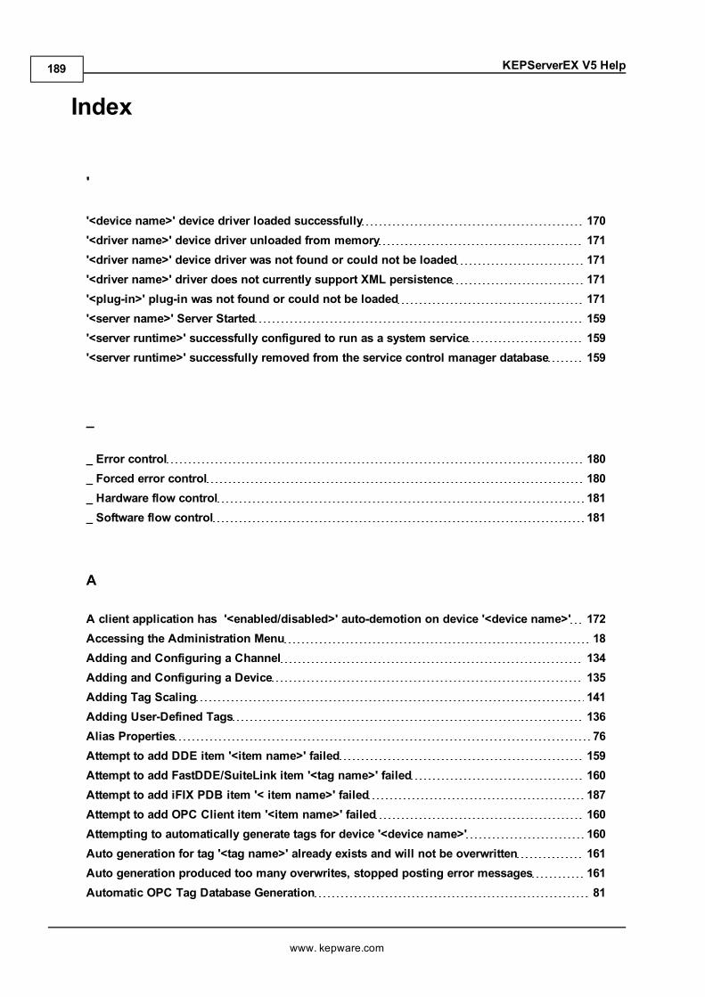
KEPServerEX V5 Help
Index
'
'<device name>' device driver loaded successfully 170'<driver name>' device driver unloaded from memory 171'<driver name>' device driver was not found or could not be loaded 171'<driver name>' driver does not currently support XML persistence 171'<plug-in>' plug-in was not found or could not be loaded 171'<server name>' Server Started 159'<server runtime>' successfully configured to run as a system service 159'<server runtime>' successfully removed from the service control manager database 159
_
_ Error control 180_ Forced error control 180_ Hardware flow control 181_ Software flow control 181
A
A client application has '<enabled/disabled>' auto-demotion on device '<device name>' 172Accessing the Administration Menu 18Adding and Configuring a Channel 134Adding and Configuring a Device 135Adding Tag Scaling 141Adding User-Defined Tags 136Alias Properties 76Attempt to add DDE item '<item name>' failed 159Attempt to add FastDDE/SuiteLink item '<tag name>' failed 160Attempt to add iFIX PDB item '< item name>' failed 187Attempt to add OPC Client item '<item name>' failed 160Attempting to automatically generate tags for device '<device name>' 160Auto generation for tag '<tag name>' already exists and will not be overwritten 161Auto generation produced too many overwrites, stopped posting error messages 161Automatic OPC Tag Database Generation 81
www. kepware.com
189
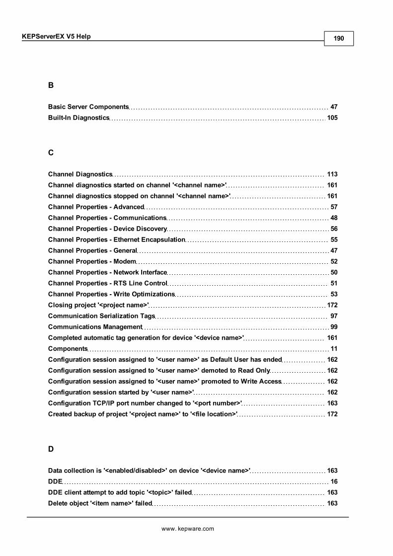
KEPServerEX V5 Help
B
Basic Server Components 47Built-In Diagnostics 105
C
Channel Diagnostics 113Channel diagnostics started on channel '<channel name>' 161Channel diagnostics stopped on channel '<channel name>' 161Channel Properties - Advanced 57Channel Properties - Communications 48Channel Properties - Device Discovery 56Channel Properties - Ethernet Encapsulation 55Channel Properties - General 47Channel Properties - Modem 52Channel Properties - Network Interface 50Channel Properties - RTS Line Control 51Channel Properties - Write Optimizations 53Closing project '<project name>' 172Communication Serialization Tags 97Communications Management 99Completed automatic tag generation for device '<device name>' 161Components 11Configuration session assigned to '<user name>' as Default User has ended 162Configuration session assigned to '<user name>' demoted to Read Only 162Configuration session assigned to '<user name>' promoted to Write Access 162Configuration session started by '<user name>' 162Configuration TCP/IP port number changed to '<port number>' 163Created backup of project '<project name>' to '<file location>' 172
D
Data collection is '<enabled/disabled>' on device '<device name>' 163DDE 16DDE client attempt to add topic '<topic>' failed 163Delete object '<item name>' failed 163
www. kepware.com
190
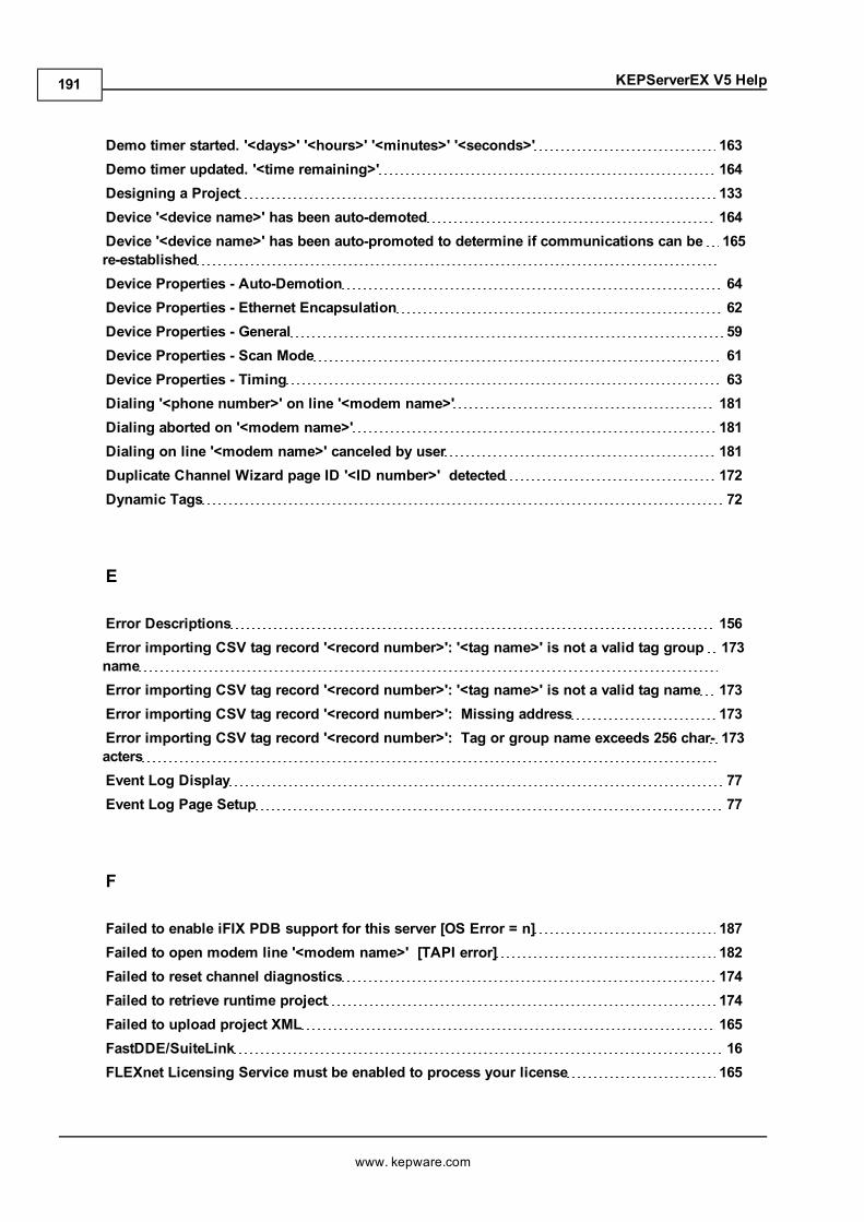
KEPServerEX V5 Help
Demo timer started. '<days>' '<hours>' '<minutes>' '<seconds>' 163Demo timer updated. '<time remaining>' 164Designing a Project 133Device '<device name>' has been auto-demoted 164Device '<device name>' has been auto-promoted to determine if communications can bere-established
165
Device Properties - Auto-Demotion 64Device Properties - Ethernet Encapsulation 62Device Properties - General 59Device Properties - Scan Mode 61Device Properties - Timing 63Dialing '<phone number>' on line '<modem name>' 181Dialing aborted on '<modem name>' 181Dialing on line '<modem name>' canceled by user 181Duplicate Channel Wizard page ID '<ID number>' detected 172Dynamic Tags 72
E
Error Descriptions 156Error importing CSV tag record '<record number>': '<tag name>' is not a valid tag groupname
173
Error importing CSV tag record '<record number>': '<tag name>' is not a valid tag name 173Error importing CSV tag record '<record number>': Missing address 173Error importing CSV tag record '<record number>': Tag or group name exceeds 256 char-acters
173
Event Log Display 77Event Log Page Setup 77
F
Failed to enable iFIX PDB support for this server [OS Error = n] 187Failed to open modem line '<modem name>' [TAPI error] 182Failed to reset channel diagnostics 174Failed to retrieve runtime project 174Failed to upload project XML 165FastDDE/SuiteLink 16FLEXnet Licensing Service must be enabled to process your license 165
www. kepware.com
191
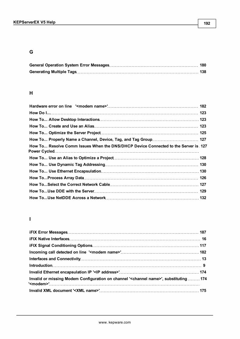
KEPServerEX V5 Help
G
General Operation System Error Messages 180Generating Multiple Tags 138
H
Hardware error on line '<modem name>' 182How Do I... 123How To... Allow Desktop Interactions 123How To... Create and Use an Alias 123How To... Optimize the Server Project 125How To... Properly Name a Channel, Device, Tag, and Tag Group 127How To... Resolve Comm Issues When the DNS/DHCP Device Connected to the Server isPower Cycled
127
How To... Use an Alias to Optimize a Project 128How To... Use Dynamic Tag Addressing 130How To... Use Ethernet Encapsulation 130How To...Process Array Data 126How To...Select the Correct Network Cable 127How To...Use DDE with the Server 129How To...Use NetDDE Across a Network 132
I
iFIX Error Messages 187iFIX Native Interfaces 16iFIX Signal Conditioning Options 117Incoming call detected on line '<modem name>' 182Interfaces and Connectivity 13Introduction 9Invalid Ethernet encapsulation IP '<IP address>' 174Invalid or missing Modem Configuration on channel '<channel name>', substituting'<modem>'
174
Invalid XML document '<XML name>' 175
www. kepware.com
192
KEPServerEX V5 Help
K
KEPServerEX 9
L
Line '<modem name>' connected 182Line '<modem name>' connected at '<baud rate>' baud 183Line '<modem name>' disconnected 183Line '<modem name>' is already in use 183Line dropped at remote site on '<modem name>' 183
M
Maximum channel count exceeded for the lite version '<driver name>' driver license 175Maximum device count exceeded for the lite version '<driver name>' driver license 175Maximum runtime tag count exceeded for the lite version '<driver name>' driver license 175Modem Auto-Dial 103Modem initialization failed on channel '<channel name>' 176Modem line closed '<modem name>' 183Modem line opened '<modem name>' 184Modem Tags 95Modem to Modem DCE '<connection parameters>' 184MODEMSETTINGS unavailable 184Module '<module>' is unsigned or has a corrupt signature. Runtime references are limitedto demo operation
165
Move object '<group>' to '<group>' failed 166Multiple Tag Generation 67
N
Navigating the Configuration 33New Channel - Communications 149New Channel - Device Driver 148New Channel - Identification 148New Channel - Summary 150
www. kepware.com
193
KEPServerEX V5 Help
New Device - ID 152New Device - Model 152New Device - Name 151New Device - Scan Mode 154New Device - Summary 155New Device - Timing 154No comm handle provided on connect for line '<modem name>' 184No device driver DLLs were loaded 166No dial tone on '<modem name>' 185
O
OPC .NET 15OPC AE 13OPC DA 13OPC Diagnostic Events 107OPC Diagnostics Window 105OPC UA 14Opening project '<project name>' 176Options - General 45Options - Runtime Connection 46
P
Phone Number Tags 102Phonebook Tags 101Process Modes 12Project Properties 34Project Properties - DDE 37Project Properties - FastDDE/Suitelink 38Project Properties - Identification 34Project Properties - iFIX PDB Settings 39Project Properties - OPC .NET 44Project Properties - OPC AE 43Project Properties - OPC DA Compliance 35Project Properties - OPC DA Settings 34Project Properties - OPC UA 41Project Startup for iFIX Applications 122
www. kepware.com
194
KEPServerEX V5 Help
Property Tags 92
R
Rejecting attempt to delete referenced object '<item name>' 166Rejecting attempt to move referenced object '<item name>' 166Remote line is busy on '<modem name>' 185Remote line is not answering on '<modem name>' 185Required schema file '<schema name>' not found 176Running the Server 133Runtime project replaced from '<project location>' 167Runtime project update failed 176
S
Saving the Project 142Server Configuration Error Messages 170Server Options 45Server Runtime Error Messages 158Server Summary Information 10Settings 23Settings - Administration 23Settings - Configuration 24Settings - Event Log 27Settings - ProgID Redirect 29Settings - Runtime Options 26Settings - Runtime Process 25Settings - User Manager 18, 30Simulation mode is '<enabled/disabled>' on device '<device name>' 167Starting '<driver name>' device driver 167Starting '<plug-in name>' plug-in 167Starting a New Project 133Starting OPC diagnostics 177Static Tags (User-Defined) 73Statistics Tags 93Stopping '<driver name>' device driver 167Stopping '<plug-in name>' plug-in 168Stopping OPC diagnostics 177
www. kepware.com
195
KEPServerEX V5 Help
System Requirements 9System Tags 85
T
Tag Group Properties 73Tag Management 79Tag Properties - General 65Tag Properties - Scaling 71TAPI configuration has changed, reinitializing... 185TAPI line initialization failed '<modem name>' 185Testing the Project 143The phone number is invalid '<phone number>' 186The tier information for feature '<feature>' is invalid 168Thin-Client Terminal Server 16
U
Unable to add channel due to driver-level failure 177Unable to add device due to driver level failure 177Unable to apply Modem Configuration on line '<modem name>' 186Unable to backup project file to '<file name/location>' 177Unable to backup project file to '<file path>' 178Unable to begin device discovery on channel '<Channel Name>' 178Unable to dial on line '<modem name>' 186Unable to enable iFIX PDB support for this server 187Unable to generate a tag database for device '<device name>'. Reason: '<reason>' 168Unable to generate a tag database for device '<device name>'. The device is not respond-ing
168
Unable to launch OPC Quick Client [Path: '<path>' OS Error: '<error>'] 178Unable to load project '<project name>' 168Unable to load the '<driver name>' driver because more than one copy exists ('<drivername>' and '<driver name>')
179
Unable to read '<tag name>' on device ' <channel name/device name>' 188Unable to start NETDDE 186Unable to use network adapter '<adapter>' on channel '<channel name>'. Using defaultnetwork adapter
179
Unable to write to item '<item name>' 169Update of object '<object>' failed 169
www. kepware.com
196
KEPServerEX V5 Help
User Properties 21Using a Modem in the Server Project 99
V
Validation error on '<tag name>': Invalid scaling parameters 179
W
What is a Channel? 47What is a Device? 59What is a Tag Group? 73What is a Tag? 65What is the Alias Map? 75What is the Event Log? 77Write request rejected on item reference '<item name>' since the device it belongs to isdisabled
169
Write request rejected on Read Only item reference '<item name>' 170
www. kepware.com
197