Embed Size (px)
Citation preview

203Catalogue 2.3
(for installation in groundwater-endangered areas)
Upper cover section, vertically adjustable,with cover Class B1
Chamber system Komfort Ø 10002
Load and transport connection hooks3
Inlet up to Ø 2004
Connection seal Ø 110(cable conduit and ventilation)5
Shaft ladder6
Corrugated chamber Ø 1300, with re-enforced,ground plate7
�
�
�
�
�
�
�
Please note the following:
When the system is installed in a groundwater-endangeredarea, the structure must be anchored on site in concrete aslift protection.
Where drop heights of more than 5 m are involved, safetymeasures must be taken on site.
In accordance with GUV V-36 and BGV D36 §5 Sect. 9 entry lad-ders and iron rungs for entry which have a fall height of morethan 5.00 m must be equipped with on-site safety measures toprevent people falling.
On request and at extra charge, the shaft structure can be fittedwith a high-quality safety package in the factory, this comprises:
Climbing protection rail made of stainless steel V4A (1.4571)
Slide mechanism made of stainless steel V4A (1.4571)
Safety harness (DIN EN 361)
Entry aid, for slotting in place (V4A)
Tender text:
KESSEL chamber system Ø 1300 made of polyethylene (PE-HD)as a collecting tank for housing a lifting/pumping station, for installation in the ground 5.330 - 5.830 mm, round version, waterproof, resistant to aggressive wastewater,comprising:
Re-enforced corrugated chamber according to DIN 16961,Ø 1300, further set-up with Komfort chamber system Ø 1000
with re-enforced, ground plate
Upper section made of thermoset 2K (Ø = 630 mm)for continuous height and level compensation
Cover Cl. B made of cast grey iron according to EN 124,with lift-out key
one PE-HD socket up to Ø 200 (inlet)
two connection seals up to Ø 110(cable conduit, ventilation/aeration)
Entry ladder made of GRP(CW= 300 mm, rung spacing 250 mm)
three load and transport connection hooks
Overall depth of the shaft structure: 6180 mm + T (Tmin= 100, Tmax= 600)
�
�
�
�
�
�
�
Individual SolutionsLift ing Stations
Pumping station in re-enforced corrugated chamber Ø 1300
Ind
ivid
ua
l S
olu
tio
ns
204 Catalogue 2.3
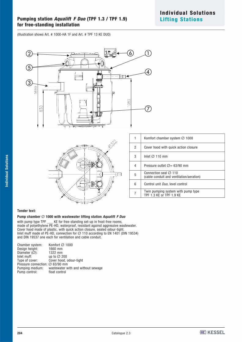
(Illustration shows Art. # 1000-HA 1F and Art. # TPF 13 KE DUO)
Individual SolutionsLift ing StationsPumping station Aqualift F Duo (TPF 1.3 / TPF 1.9)
for free-standing installation
1 Schachtsy2 Deckelhau
Schnellspa3 Zulauf DN
(Øa= 110 4 Druckabga
(Øa= 63/95 Anschluss
Be-/Entlüft6 Schaltgerä
Niveauste7 Doppelpum
TPF 1,3 K
4
1 2
5
3
6
7
Tender text:
Pump chamber Ø 1000 with wastewater lifting station Aqualift F Duowith pump type TPF ___ KE for free-standing set-up in frost-free rooms, made of polyethylene PE-HD, waterproof, resistant against aggressive wastewater. Cover hood made of plastic, with quick action closure, sealed odour-tight.Inlet muff made of PE-HD, connection for Ø 110 according to EN 1401 (DIN 19534) and DIN 19537 one each for ventilation and cable conduit.
Chamber system: Komfort Ø 1000Design height: 1660 mmDiameter (Ø): 1322 mmInlet muff: up to Ø 200Type of cover: Cover hood, odour-tightPressure connection: Ø 63/90 mmPumping medium: wastewater with and without sewagePump control: float control
Komfort chamber system Ø 10001
Cover hood with quick action closure2
Inlet Ø 110 mm3
Pressure outlet Ø= 63/90 mm4
Connection seal Ø 110(cable conduit and ventilation/aeration)5
Control unit Duo, level control6
Twin pumping system with pump typeTPF 1.3 KE or TPF 1.9 KE7
�
�
���
�
�
Ind
ivid
ua
l S
olu
tio
ns
205Catalogue 2.3
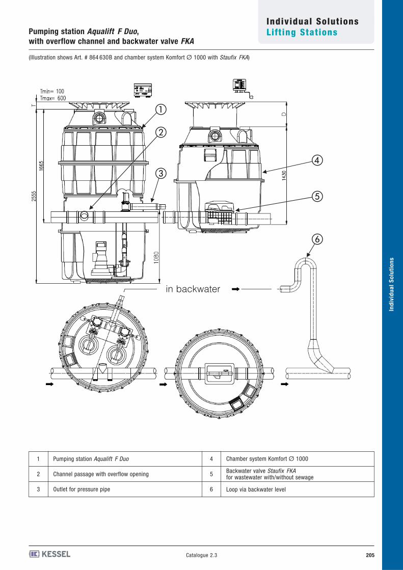
(Illustration shows Art. # 864 630B and chamber system Komfort Ø 1000 with Staufix FKA)
Individual SolutionsLift ing StationsPumping station Aqualift F Duo,
with overflow channel and backwater valve FKA
3 4
5
1
2
6
Pumping station Aqualift F Duo1
Channel passage with overflow opening2
Outlet for pressure pipe3
Chamber system Komfort Ø 1000
Backwater valve Staufix FKAfor wastewater with/without sewage
Loop via backwater level
4
5
6
�
�
��
�
�
in backwater
Ind
ivid
ua
l S
olu
tio
ns
D
206 Catalogue 2.3
Ind
ivid
ua
l S
olu
tio
ns
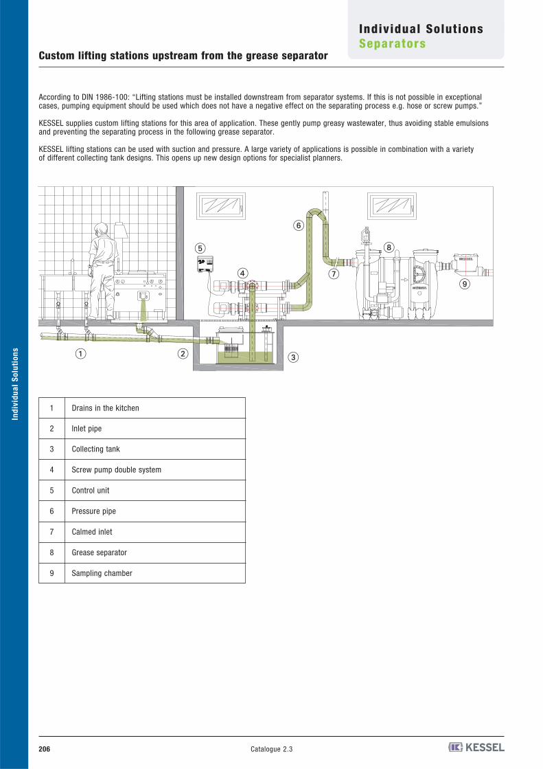
According to DIN 1986-100: “Lifting stations must be installed downstream from separator systems. If this is not possible in exceptionalcases, pumping equipment should be used which does not have a negative effect on the separating process e.g. hose or screw pumps.”
KESSEL supplies custom lifting stations for this area of application. These gently pump greasy wastewater, thus avoiding stable emulsions and preventing the separating process in the following grease separator.
KESSEL lifting stations can be used with suction and pressure. A large variety of applications is possible in combination with a variety of different collecting tank designs. This opens up new design options for specialist planners.
Drains in the kitchen1
Inlet pipe2
Collecting tank3
Screw pump double system4
Control unit5
Pressure pipe6
Calmed inlet7
Grease separator8
Sampling chamber9
� � �
�
�
�
�
Individual SolutionsSeparators
Custom lifting stations upstream from the grease separator
207Catalogue 2.3
Individual SolutionsSeparators
Grease separator for installation in the ground
Ind
ivid
ua
l S
olu
tio
ns
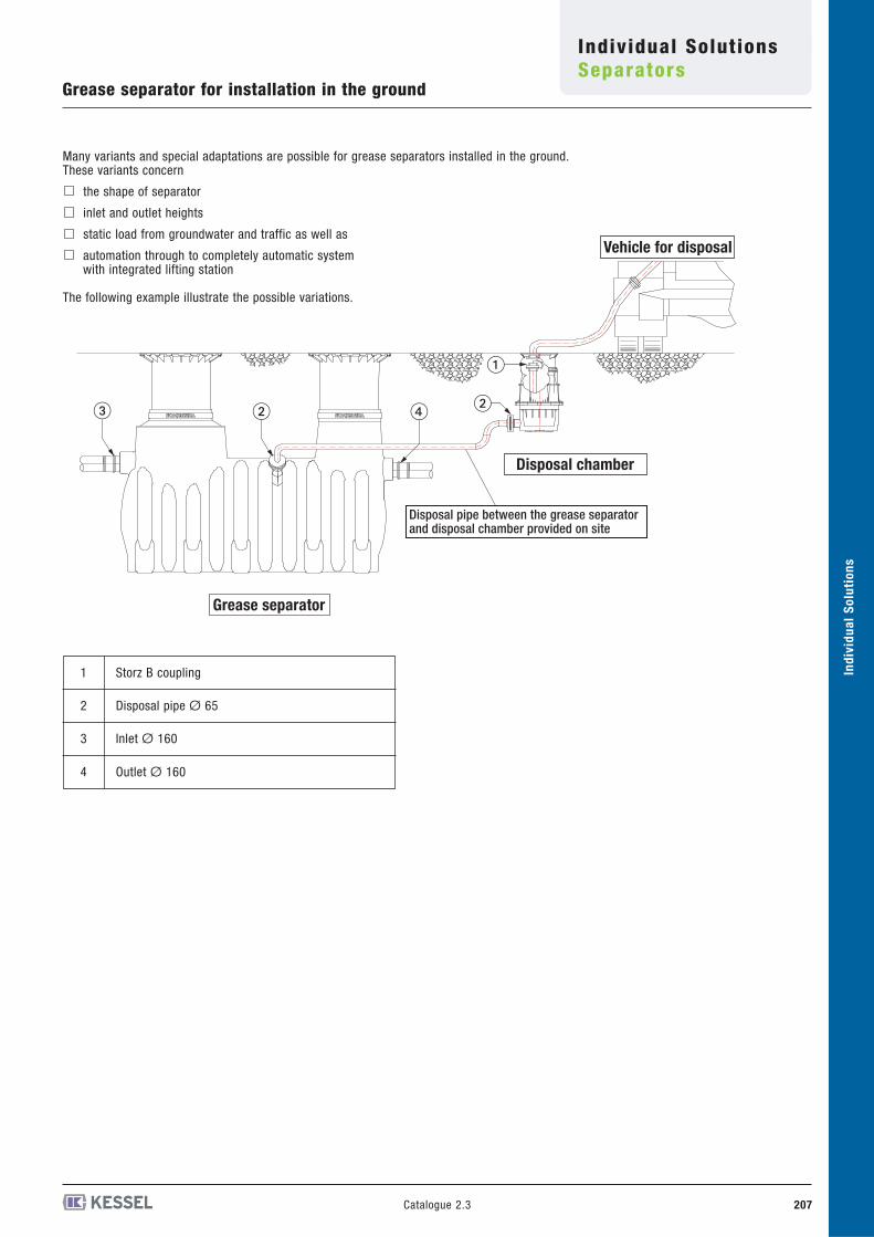
Many variants and special adaptations are possible for grease separators installed in the ground.These variants concern
the shape of separator
inlet and outlet heights
static load from groundwater and traffic as well as
automation through to completely automatic systemwith integrated lifting station
The following example illustrate the possible variations.
Storz B coupling1
Disposal pipe Ø 652
Inlet Ø 1603
Outlet Ø 1604
Vehicle for disposal
Disposal chamber
Grease separator
Disposal pipe between the grease separator and disposal chamber provided on site
�
�� ��
208 Catalogue 2.3
Ind
ivid
ua
l S
olu
tio
ns
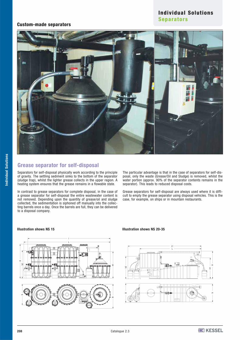
Custom-made separators
Grease separator for self-disposal
Separators for self-disposal physically work according to the principleof gravity. The settling sediment sinks to the bottom of the separator(sludge trap), whilst the lighter grease collects in the upper region. Aheating system ensures that the grease remains in a flowable state.
In contrast to grease separators for complete disposal, in the case ofa grease separator for self-disposal the entire wastewater content isnot removed. Depending upon the quantity of grease/oil and sludgecollected, the sedimentation is siphoned off manually into the collec-ting barrels once a day. Once the barrels are full, they can be deliveredto a disposal company.
The particular advantage is that in the case of separators for self-dis-posal, only the waste (Grease/Oil and Sludge) is removed, whilst thewater portion (approx. 90% of the separator contents remains in theseparator). This leads to reduced disposal costs.
Grease separators for self-disposal are always used where it is diffi-cult to empty the grease separator using disposal vehicles. This is thecase, for example, on ships or in mountain restaurants.
L
l
h1h2H
b
B
Individual SolutionsSeparators
LL1
h1H
b
h2B
Illustration shows NS 15 Illustration shows NS 20-35
Ind
ivid
ua
l S
olu
tio
ns
209Catalogue 2.3
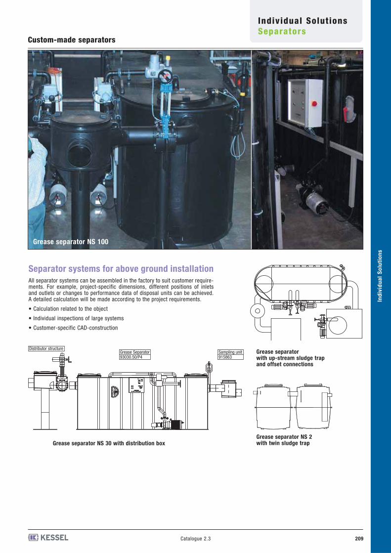
Custom-made separators
Separator systems for above ground installation
All separator systems can be assembled in the factory to suit customer require-ments. For example, project-specific dimensions, different positions of inletsand outlets or changes to performance data of disposal units can be achieved.A detailed calculation will be made according to the project requirements.
• Calculation related to the object
• Individual inspections of large systems
• Customer-specific CAD-construction
Grease separator NS 2 with twin sludge trapGrease separator NS 30 with distribution box
Grease separator with up-stream sludge trap and offset connections
Grease separator NS 100
Distributor structureGrease Separator93030.50/P4
Sampling unit915863
Individual SolutionsSeparators
Ind
ivid
ua
l S
olu
tio
ns
Catalogue 2.3210
Individual SolutionsSeparators
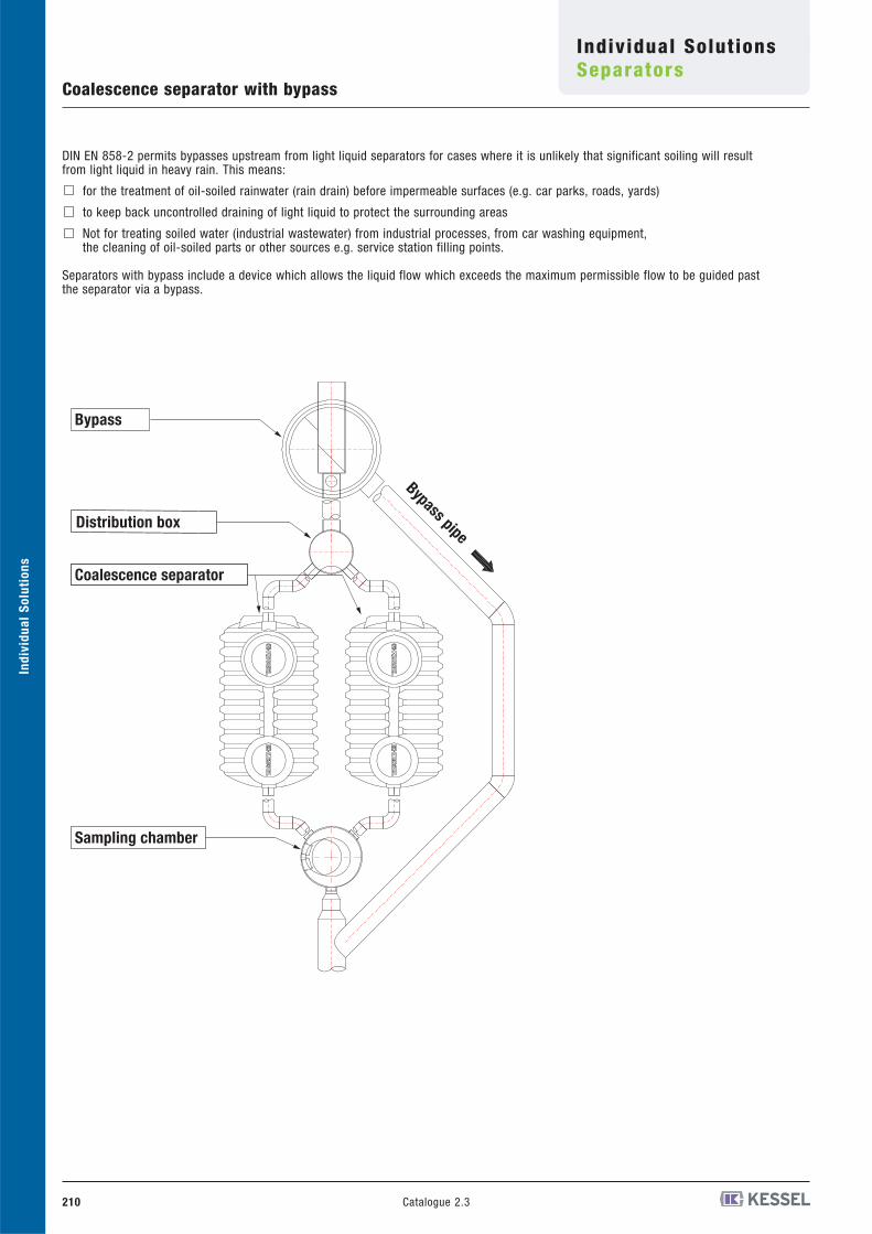
Coalescence separator with bypass
DIN EN 858-2 permits bypasses upstream from light liquid separators for cases where it is unlikely that significant soiling will result from light liquid in heavy rain. This means:
for the treatment of oil-soiled rainwater (rain drain) before impermeable surfaces (e.g. car parks, roads, yards)
to keep back uncontrolled draining of light liquid to protect the surrounding areas
Not for treating soiled water (industrial wastewater) from industrial processes, from car washing equipment,the cleaning of oil-soiled parts or other sources e.g. service station filling points.
Separators with bypass include a device which allows the liquid flow which exceeds the maximum permissible flow to be guided pastthe separator via a bypass.
Sampling chamber
Coalescence separator
Distribution box
Bypass
Bypass pipe
Ind
ivid
ua
l S
olu
tio
ns
Catalogue 2.3 211
Individual SolutionsSeparators
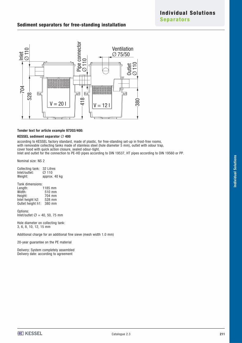
Sediment separators for free-standing installation
Tender text for article example 97202/400:
KESSEL sediment separator Ø 400
according to KESSEL factory standard, made of plastic, for free-standing set-up in frost-free rooms, with removable collecting tanks made of stainless steel (hole diameter 5 mm), outlet with odour trap, cover hood with quick action closure, sealed odour-tight.Inlet and outlet for the connection to PE-HD pipes according to DIN 19537, HT pipes according to DIN 19560 or PP.
Nominal size: NS 2
Collecting tank: 32 LitresInlet/outlet: Ø 110Weight: approx. 40 kg
Tank dimensions:Length: 1185 mmWidth: 510 mmHeight: 704 mmInlet height h2: 528 mmOutlet height h1: 380 mm
Options:Inlet/outlet Ø = 40, 50, 75 mm
Hole diameter on collecting tank:3, 6, 8, 10, 12, 15 mm
Additional charge for an additional fine sieve (mesh width 1.0 mm)
20-year guarantee on the PE material
Delivery: System completely assembledDelivery date: according to agreement
Outle
tØ
110
Inle
tØ
110 Ventilation
Ø 75/50
704
528
418
380
V = 12 lV = 20 l
Pipe
con
nect
orØ
110
212 Catalogue 2.3
Ind
ivid
ua
l S
olu
tio
ns
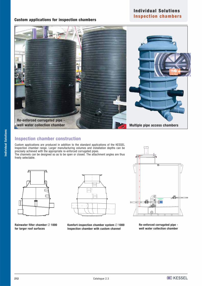
Rainwater filter chamber Ø 1000
for larger roof surfaces
Re-enforced corrugated pipe -
well water collection chamber
Komfort-inspection chamber system Ø 1000
Inspection chamber with custom channel
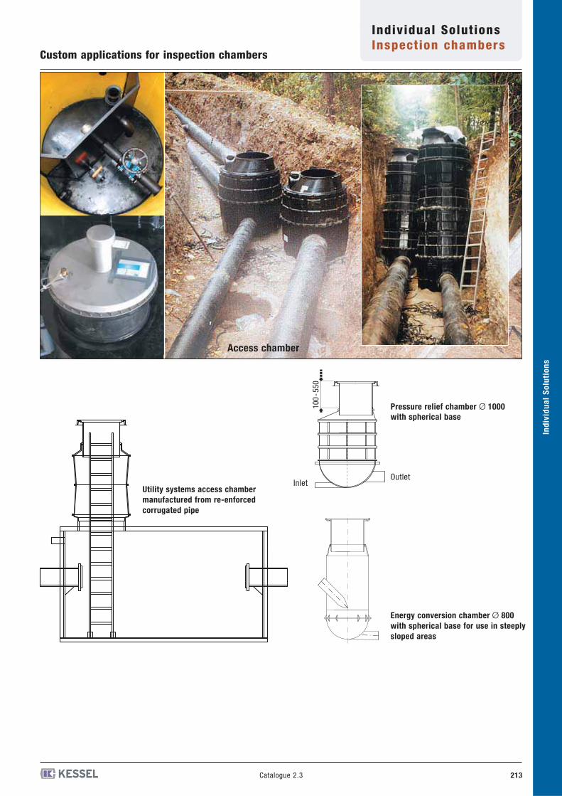
Custom applications for inspection chambers
Inspection chamber construction
Custom applications are produced in addition to the standard applications of the KESSELInspection chamber range. Larger manufacturing volumes and installation depths can beprecisely achieved with the appropriate re-enforced corrugated pipes.The channels can be designed so as to be open or closed. The attachment angles are thusfreely selectable.
Re-enforced corrugated pipe -
well water collection chamber Multiple pipe access chambers
Individual SolutionsInspection chambers
Ind
ivid
ua
l S
olu
tio
ns
213Catalogue 2.3
Energy conversion chamber Ø 800
with spherical base for use in steeply
sloped areas
Custom applications for inspection chambers
Utility systems access chamber
manufactured from re-enforced
corrugated pipe
Pressure relief chamber Ø 1000
with spherical base
100
-550
InletOutlet
Access chamber
Individual SolutionsInspection chambers