Embed Size (px)
Citation preview

IngenIería e InvestIgacIón vol. 37 n.° 3, december - 2017 (115-123)
115
Kinematics based physical modelling and experimental analysis of the shoulder joint complex
Modelo físico basado en cinemática y análisis experimental del complejo articular del hombro
Diego Almeida-Galárraga1, Antonio Ros-Felip2, Virginia Álvarez-Sánchez3, Fernando Marco-Martinez4, and Laura Serrano-Mateo5
ABSTRACT
The purpose of this work is to develop an experimental physical model of the shoulder joint complex. The aim of this research is to validate the model built and identify the forces on specified positions of this joint. The shoulder musculoskeletal structures have been replicated to evaluate the forces to which muscle fibres are subjected in different equilibrium positions: 60º flexion, 60º abduction and 30º abduction and flexion. The physical model represents, quite accurately, the shoulder complex. It has 12 real degrees of freedom, which allows motions such as abduction, flexion, adduction and extension and to calculate the resultant forces of the represented muscles. The built physical model is versatile and easily manipulated and represents, above all, a model for teaching applications on anatomy and shoulder joint complex biomechanics. Moreover, it is a valid research tool on muscle actions related to abduction, adduction, flexion, extension, internal and external rotation motions or combination among them.
Keywords: Physical model, shoulder joint, experimental technique, tensions analysis, biomechanics, kinetics, cinematic.
RESUMEN
Este trabajo consiste en desarrollar un modelo físico experimental del complejo articular del hombro. El objetivo en esta investigación es validar el modelo construido e identificar las fuerzas en posiciones específicas de esta articulación. Se han reproducido las estructuras musculo-esqueléticas del hombro para evaluar las fuerzas a las que están sometidas las fibras musculares en diferentes posiciones de equilibrio: flexión 60º, abducción 60º y aducción más flexión 30º. El modelo físico representa con suficiente aproximación a la realidad el complejo del hombro; posee 12 grados reales de libertad, lo cual permite realizar movimientos como abducción, flexión, aducción y extensión y calcular las fuerzas resultantes de los músculos representados. El modelo físico construido es versátil y fácilmente manipulable y constituye, por encima de todo, un modelo para aplicaciones didácticas en anatomía y biomecánica del complejo articular del hombro. Así mismo, es una herramienta de investigación válida sobre las acciones musculares asociadas a los movimientos de abducción, aducción, flexión, extensión, rotación interna y externa o combinaciones de los mismos.
Palabras clave: Modelo físico, articulación del hombro, técnica experimental, análisis de tensiones, biomecánica, cinética, cinemática.
Received: March 3rd, 2017Accepted: August 30th, 2017
DOI: http://dx.doi.org/10.15446/ing.investig.v37n3.63144
2 Mechanical Engineering, Universidad Politécnica de Madrid (UPM), Spain. Ph.D., Mechanical Engineering, UPM, Spain. Affiliation: Department of Me-chanical, UPM, Spain. E-mail: [email protected]
3 Industrial Engineer Mechanical-Machines, UPM, Spain. M.Sc. Professional Development, Universidad de Alcalá, Spain. Affiliation: Department of Me-chanical, UPM, Spain. E-mail: [email protected]
4 MD. Medical Degree, Universidad Complutense de Madrid, Spain. Ph.D., Me-dicine, Universidad Complutense de Madrid, Spain. Affiliation: Department of Orthopaedic Surgery and Traumatology, Hospital Clínico San Carlos, Spain. E-mail: [email protected]
5 MD. Medical Degree, Universidad Autónoma de Madrid, Spain. Affiliation: Department of Orthopaedic Surgery and Traumatology, Hospital Clínico San Carlos, Spain. E-mail: [email protected]
How to cite: Almeida-Galárraga, D.A., Ros-Felip, A., Álvarez-Sánchez, V., F. Marco-Martinez, F., Serrano-Mateo, L. (2017). Kinematics based physical modelling and experimental analysis of the shoulder joint complex. Ingenie-ría e Investigación, 37(3), 115-123 DOI: 10.15446/ing.investig.v37n3.63144
Attribution 4.0 International (CC BY 4.0) Share - Adapt
Introduction
Biomechanics, through the development of joint physical models, allow us to obtain quantitative and qualitative descriptions of the joint function, useful data for both clinical practice and research (Limb, 2014). The shoulder joint complex presents a challenge regarding the development of physical models due to its complexity, composed by four joints (glenohumeral, acromioclavicular, scapulothoracic and sternoclavicular) and a wide variety of muscle-ligamentous structures (Kapandji, 2012).
The shoulder joint complex has several Degrees of Freedom (DoF) and it has greater amplitude of motions than any
1 Electronics and Telecommunications Engineering, Universidad de las Fuerzas Armadas, Ecuador. M.Sc. Mobile Network Information and Communication Technologies, Universidad de Cantabria, Spain. Affiliation: Department of Me-chanical, Universidad Politécnica de Madrid (UPM), Spain.
1 E-mail: [email protected]
KINEMATICS BASED PHYSICAL MODELLING AND EXPERIMENTAL ANALYSIS OF THE SHOULDER JOINT COMPLEX
INGENIERÍA E INVESTIGACIÓN VOL. 37 N.° 3, DECEMBER - 2017 (115-123)116
other joints of the human body (Hurov, 2009). In this way, it performs the three pairs of basic motions (fl exion/extension, abduction/adduction and internal/external rotation), and the sum of the three groups results in circumduction.
The knowledge on the shoulder biomechanical function is essential to understand the physiology and pathology associated to this joint. Multiple theoretical models have been proposed for biomechanical studies: cadaver-based studies (Van der Helm & Veenbaas, 1991), fi nite-element studies (Büchler et al., 2002), kinematic studies (Klopčar et al., 2007), kinematic studies using skin-markers (Jackson et al., 2012), force prediction models of the glenohumeral group (Charlton & Johnson, 2006).
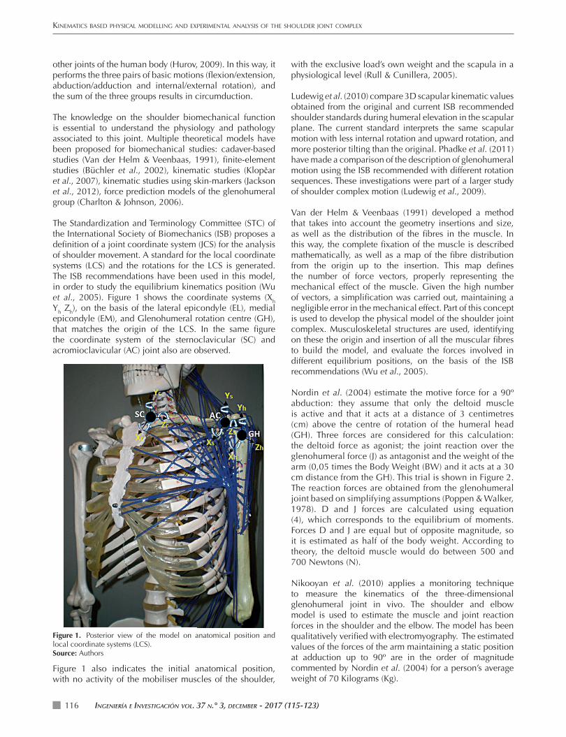
The Standardization and Terminology Committee (STC) of the International Society of Biomechanics (ISB) proposes a defi nition of a joint coordinate system (JCS) for the analysis of shoulder movement. A standard for the local coordinate systems (LCS) and the rotations for the LCS is generated. The ISB recommendations have been used in this model, in order to study the equilibrium kinematics position (Wu et al., 2005). Figure 1 shows the coordinate systems (Xh Yh Zh), on the basis of the lateral epicondyle (EL), medial epicondyle (EM), and Glenohumeral rotation centre (GH), that matches the origin of the LCS. In the same fi gure the coordinate system of the sternoclavicular (SC) and acromioclavicular (AC) joint also are observed.
with the exclusive load’s own weight and the scapula in a physiological level (Rull & Cunillera, 2005).
Ludewig et al. (2010) compare 3D scapular kinematic values obtained from the original and current ISB recommended shoulder standards during humeral elevation in the scapular plane. The current standard interprets the same scapular motion with less internal rotation and upward rotation, and more posterior tilting than the original. Phadke et al. (2011) have made a comparison of the description of glenohumeral motion using the ISB recommended with different rotation sequences. These investigations were part of a larger study of shoulder complex motion (Ludewig et al., 2009).
Van der Helm & Veenbaas (1991) developed a method that takes into account the geometry insertions and size, as well as the distribution of the fi bres in the muscle. In this way, the complete fi xation of the muscle is described mathematically, as well as a map of the fi bre distribution from the origin up to the insertion. This map defi nes the number of force vectors, properly representing the mechanical effect of the muscle. Given the high number of vectors, a simplifi cation was carried out, maintaining a negligible error in the mechanical effect. Part of this concept is used to develop the physical model of the shoulder joint complex. Musculoskeletal structures are used, identifying on these the origin and insertion of all the muscular fi bres to build the model, and evaluate the forces involved in different equilibrium positions, on the basis of the ISB recommendations (Wu et al., 2005).
Nordin et al. (2004) estimate the motive force for a 90º abduction: they assume that only the deltoid muscle is active and that it acts at a distance of 3 centimetres (cm) above the centre of rotation of the humeral head (GH). Three forces are considered for this calculation: the deltoid force as agonist; the joint reaction over the glenohumeral force (J) as antagonist and the weight of the arm (0,05 times the Body Weight (BW) and it acts at a 30 cm distance from the GH). This trial is shown in Figure 2. The reaction forces are obtained from the glenohumeral joint based on simplifying assumptions (Poppen & Walker, 1978). D and J forces are calculated using equation (4), which corresponds to the equilibrium of moments. Forces D and J are equal but of opposite magnitude, so it is estimated as half of the body weight. According to theory, the deltoid muscle would do between 500 and 700 Newtons (N).
Nikooyan et al. (2010) applies a monitoring technique to measure the kinematics of the three-dimensional glenohumeral joint in vivo. The shoulder and elbow model is used to estimate the muscle and joint reaction forces in the shoulder and the elbow. The model has been qualitatively verifi ed with electromyography. The estimated values of the forces of the arm maintaining a static position at adduction up to 90º are in the order of magnitude commented by Nordin et al. (2004) for a person’s average weight of 70 Kilograms (Kg).
Figure 1. Posterior view of the model on anatomical position and local coordinate systems (LCS).Source: Authors
Figure 1 also indicates the initial anatomical position, with no activity of the mobiliser muscles of the shoulder,
INGENIERÍA E INVESTIGACIÓN VOL. 37 N.° 3, DECEMBER - 2017 (115-123) 117
ALMEIDA, ROS, ÁLVAREZ, MARCO, AND SERRANO
Figure 2. Simplifi ed equilibrium.Source: Authors
Negrete-Mundo & Torres-Zavalab (2016) determine the normal force of the shoulder at 90º abduction in healthy individuals in both arms (dominant and non-dominant), through a muscle force acquisition system.
This study proposes a real scale physical model of the shoulder joint in order to understand its biomechanical function and also, for future researches. This work is carried out in real scale because it is diffi cult to represent the force actions associated to the shoulder since the multiple muscles involved act in different ways. The aim of this research is to design, develop and validate an experimental method of the physical model applicable to the force analysis to which the shoulder joint complex is subjected in the considered static equilibrium positions.
To develop a physical model of the shoulder, an appropriate bone moulding technique is required, and mount it on the full anatomical model of the human skeleton (Jago, 2010). Below, the muscular insertions and origins are moulded (Drake et al., 2009). The muscular actions are simulated with orthodontic elastomeric chains (Nordin et al., 2004); the equilibrium kinematics positions are studied and fi nally, the results obtained from the comparison with other authors are analysed.
The model has 12 real degrees of freedom, which allows to make motions such as abduction, fl exion, adduction and extension; the resultant forces of the muscles in the static equilibrium positions are considered acceptable, compared with the literature of the agonist and antagonist muscles involved in the three equilibrium positions studied (Nordin et al., 2004; Kapandji, 2012; Drake et al., 2009).
Materials and Methods
Bone moulding technique
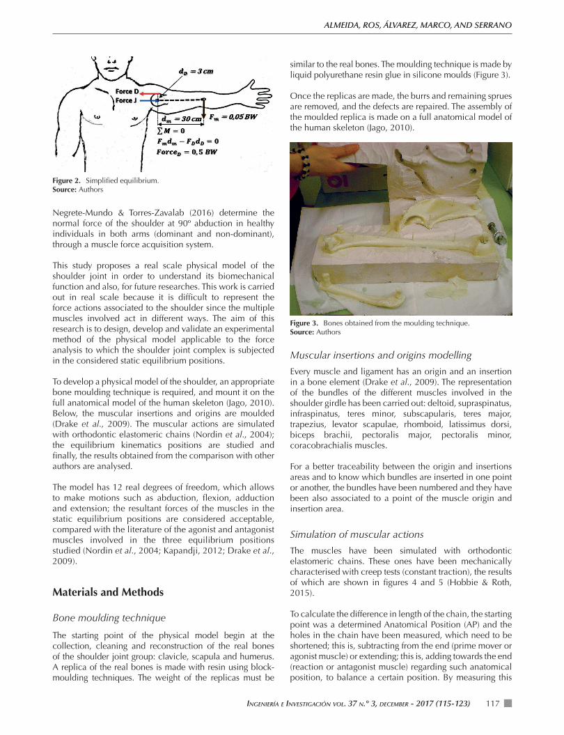
The starting point of the physical model begin at the collection, cleaning and reconstruction of the real bones of the shoulder joint group: clavicle, scapula and humerus. A replica of the real bones is made with resin using block-moulding techniques. The weight of the replicas must be
similar to the real bones. The moulding technique is made by liquid polyurethane resin glue in silicone moulds (Figure 3).
Once the replicas are made, the burrs and remaining sprues are removed, and the defects are repaired. The assembly of the moulded replica is made on a full anatomical model of the human skeleton (Jago, 2010).
Figure 3. Bones obtained from the moulding technique.Source: Authors
Muscular insertions and origins modelling
Every muscle and ligament has an origin and an insertion in a bone element (Drake et al., 2009). The representation of the bundles of the different muscles involved in the shoulder girdle has been carried out: deltoid, supraspinatus, infraspinatus, teres minor, subscapularis, teres major, trapezius, levator scapulae, rhomboid, latissimus dorsi, biceps brachii, pectoralis major, pectoralis minor, coracobrachialis muscles.
For a better traceability between the origin and insertions areas and to know which bundles are inserted in one point or another, the bundles have been numbered and they have been also associated to a point of the muscle origin and insertion area.
Simulation of muscular actions
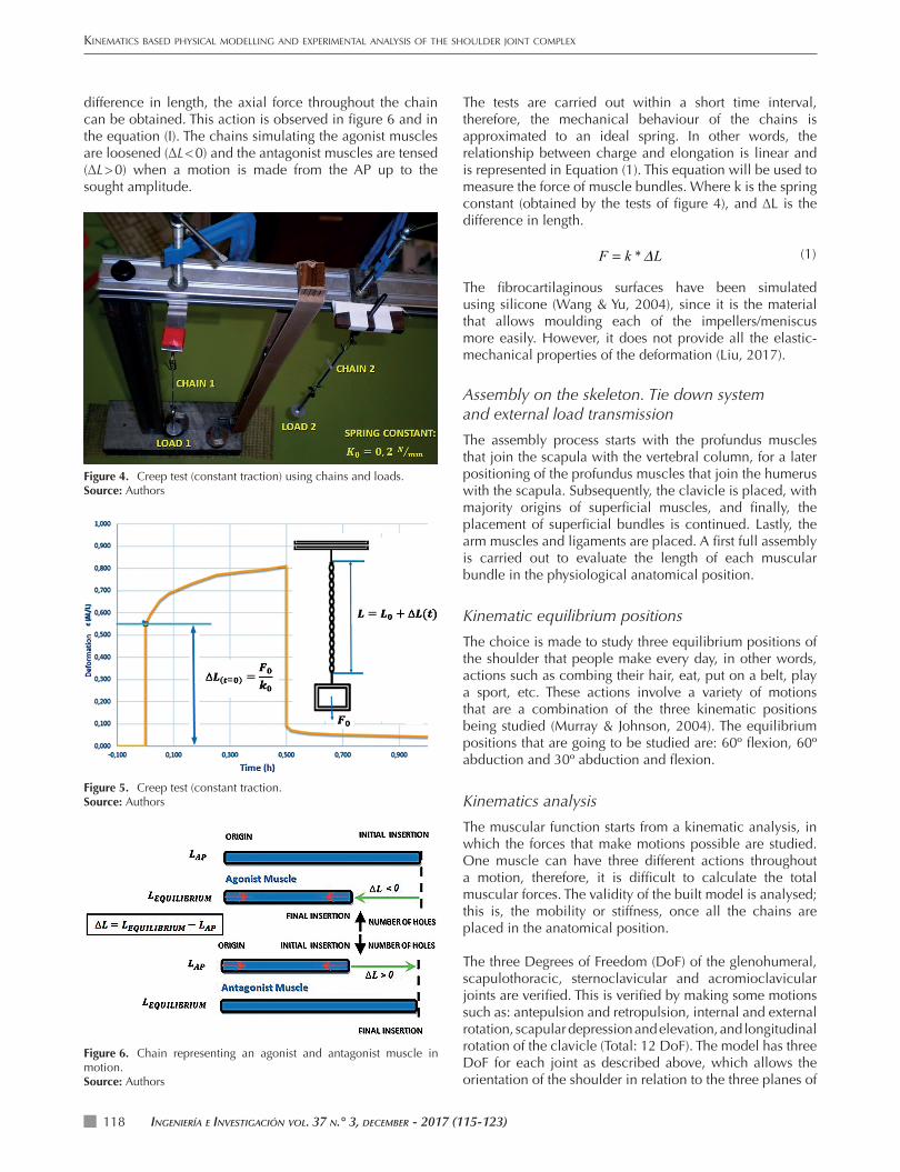
The muscles have been simulated with orthodontic elastomeric chains. These ones have been mechanically characterised with creep tests (constant traction), the results of which are shown in fi gures 4 and 5 (Hobbie & Roth, 2015).
To calculate the difference in length of the chain, the starting point was a determined Anatomical Position (AP) and the holes in the chain have been measured, which need to be shortened; this is, subtracting from the end (prime mover or agonist muscle) or extending; this is, adding towards the end (reaction or antagonist muscle) regarding such anatomical position, to balance a certain position. By measuring this
KINEMATICS BASED PHYSICAL MODELLING AND EXPERIMENTAL ANALYSIS OF THE SHOULDER JOINT COMPLEX
INGENIERÍA E INVESTIGACIÓN VOL. 37 N.° 3, DECEMBER - 2017 (115-123)118
difference in length, the axial force throughout the chain can be obtained. This action is observed in fi gure 6 and in the equation (I). The chains simulating the agonist muscles are loosened (∆L < 0) and the antagonist muscles are tensed (∆L > 0) when a motion is made from the AP up to the sought amplitude.
The tests are carried out within a short time interval, therefore, the mechanical behaviour of the chains is approximated to an ideal spring. In other words, the relationship between charge and elongation is linear and is represented in Equation (1). This equation will be used to measure the force of muscle bundles. Where k is the spring constant (obtained by the tests of fi gure 4), and ∆L is the difference in length.
F = k *ΔL (1)
The fi brocartilaginous surfaces have been simulated using silicone (Wang & Yu, 2004), since it is the material that allows moulding each of the impellers/meniscus more easily. However, it does not provide all the elastic-mechanical properties of the deformation (Liu, 2017).
Assembly on the skeleton. Tie down system and external load transmission
The assembly process starts with the profundus muscles that join the scapula with the vertebral column, for a later positioning of the profundus muscles that join the humerus with the scapula. Subsequently, the clavicle is placed, with majority origins of superfi cial muscles, and fi nally, the placement of superfi cial bundles is continued. Lastly, the arm muscles and ligaments are placed. A fi rst full assembly is carried out to evaluate the length of each muscular bundle in the physiological anatomical position.
Kinematic equilibrium positions
The choice is made to study three equilibrium positions of the shoulder that people make every day, in other words, actions such as combing their hair, eat, put on a belt, play a sport, etc. These actions involve a variety of motions that are a combination of the three kinematic positions being studied (Murray & Johnson, 2004). The equilibrium positions that are going to be studied are: 60º fl exion, 60º abduction and 30º abduction and fl exion.
Kinematics analysis
The muscular function starts from a kinematic analysis, in which the forces that make motions possible are studied. One muscle can have three different actions throughout a motion, therefore, it is diffi cult to calculate the total muscular forces. The validity of the built model is analysed; this is, the mobility or stiffness, once all the chains are placed in the anatomical position.
The three Degrees of Freedom (DoF) of the glenohumeral, scapulothoracic, sternoclavicular and acromioclavicular joints are verifi ed. This is verifi ed by making some motions such as: antepulsion and retropulsion, internal and external rotation, scapular depression and elevation, and longitudinal rotation of the clavicle (Total: 12 DoF). The model has three DoF for each joint as described above, which allows the orientation of the shoulder in relation to the three planes of
Figure 4. Creep test (constant traction) using chains and loads.Source: Authors
Figure 5. Creep test (constant traction.Source: Authors
Figure 6. Chain representing an agonist and antagonist muscle in motion.Source: Authors
IngenIería e InvestIgacIón vol. 37 n.° 3, december - 2017 (115-123) 119
ALMEIDA, ROS, ÁLVAREZ, MARCO, AND SERRANO
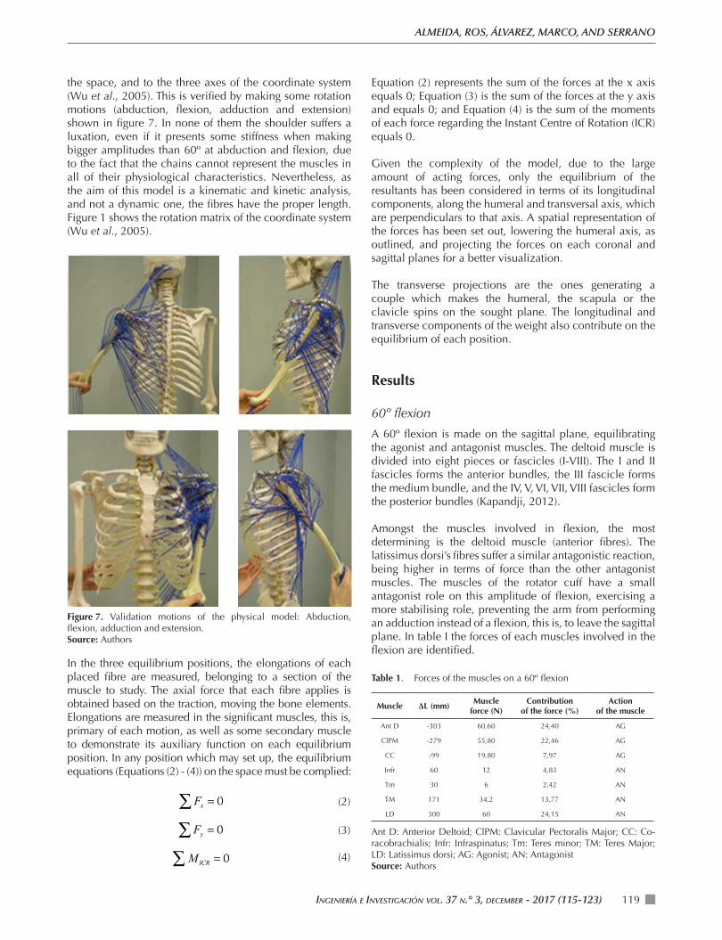
the space, and to the three axes of the coordinate system (Wu et al., 2005). This is verified by making some rotation motions (abduction, flexion, adduction and extension) shown in figure 7. In none of them the shoulder suffers a luxation, even if it presents some stiffness when making bigger amplitudes than 60º at abduction and flexion, due to the fact that the chains cannot represent the muscles in all of their physiological characteristics. Nevertheless, as the aim of this model is a kinematic and kinetic analysis, and not a dynamic one, the fibres have the proper length. Figure 1 shows the rotation matrix of the coordinate system (Wu et al., 2005).
Equation (2) represents the sum of the forces at the x axis equals 0; Equation (3) is the sum of the forces at the y axis and equals 0; and Equation (4) is the sum of the moments of each force regarding the Instant Centre of Rotation (ICR) equals 0.
Given the complexity of the model, due to the large amount of acting forces, only the equilibrium of the resultants has been considered in terms of its longitudinal components, along the humeral and transversal axis, which are perpendiculars to that axis. A spatial representation of the forces has been set out, lowering the humeral axis, as outlined, and projecting the forces on each coronal and sagittal planes for a better visualization.
The transverse projections are the ones generating a couple which makes the humeral, the scapula or the clavicle spins on the sought plane. The longitudinal and transverse components of the weight also contribute on the equilibrium of each position.
Results
60º flexion
A 60º flexion is made on the sagittal plane, equilibrating the agonist and antagonist muscles. The deltoid muscle is divided into eight pieces or fascicles (I-VIII). The I and II fascicles forms the anterior bundles, the III fascicle forms the medium bundle, and the IV, V, VI, VII, VIII fascicles form the posterior bundles (Kapandji, 2012).
Amongst the muscles involved in flexion, the most determining is the deltoid muscle (anterior fibres). The latissimus dorsi’s fibres suffer a similar antagonistic reaction, being higher in terms of force than the other antagonist muscles. The muscles of the rotator cuff have a small antagonist role on this amplitude of flexion, exercising a more stabilising role, preventing the arm from performing an adduction instead of a flexion, this is, to leave the sagittal plane. In table I the forces of each muscles involved in the flexion are identified.
Table 1. Forces of the muscles on a 60º flexion
Muscle ΔL (mm)Muscle
force (N)Contribution
of the force (%)Action
of the muscle
Ant D -303 60,60 24,40 AG
ClPM -279 55,80 22,46 AG
CC -99 19,80 7,97 AG
Infr 60 12 4,83 AN
Tm 30 6 2,42 AN
TM 171 34,2 13,77 AN
LD 300 60 24,15 AN
Ant D: Anterior Deltoid; ClPM: Clavicular Pectoralis Major; CC: Co-racobrachialis; Infr: Infraspinatus; Tm: Teres minor; TM: Teres Major; LD: Latissimus dorsi; AG: Agonist; AN: AntagonistSource: Authors
Figure 7. Validation motions of the physical model: Abduction, flexion, adduction and extension.Source: Authors
In the three equilibrium positions, the elongations of each placed fibre are measured, belonging to a section of the muscle to study. The axial force that each fibre applies is obtained based on the traction, moving the bone elements. Elongations are measured in the significant muscles, this is, primary of each motion, as well as some secondary muscle to demonstrate its auxiliary function on each equilibrium position. In any position which may set up, the equilibrium equations (Equations (2) - (4)) on the space must be complied:
Fx = 0∑ (2)
Fy = 0∑ (3)
MICR = 0∑ (4)
KINEMATICS BASED PHYSICAL MODELLING AND EXPERIMENTAL ANALYSIS OF THE SHOULDER JOINT COMPLEX
INGENIERÍA E INVESTIGACIÓN VOL. 37 N.° 3, DECEMBER - 2017 (115-123)120
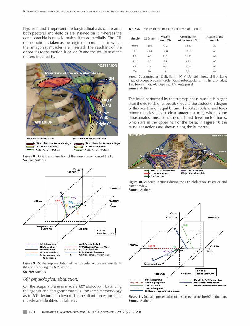
Figures 8 and 9 represent the longitudinal axis of the arm, both pectoral and deltoids are inserted on it, whereas the coracobrachialis muscle makes it more medially. The ICR of the motion is taken as the origin of coordinates, in which the antagonist muscles are inserted. The resultant of the opposites to the motion is called Rt and the resultant of the motors is called Ft.
Table 2. Forces of the muscles on a 60º abduction
Muscle ΔL (mm)Muscle
force (N)Contribution
of the force (%)Action of the
muscle
Supra -216 43,2 38,30 AG
Delt -174 34,8 30,85 AG
LHBb -66 13,2 11,70 AG
Subs -27 5,4 4,79 AG
Infr -51 10,2 9,04 AG
Tm 30 6 5,32 AN
Supra: Supraspinatus; Delt: II, III, IV, V Deltoid fi bres; LHBb: Long head of biceps brachii muscle; Subs: Subscapularis; Infr: Infraspinatus; Tm: Teres minor; AG: Agonist; AN: AntagonistSource: Authors
The force performed by the supraspinatus muscle is bigger than the deltoids one, possibly due to the abduction degree of this position on equilibrium. The subscapularis and teres minor muscles play a clear antagonist role, whereas the infraspinatus muscle has neutral and level motor fi bres, which are in the upper half of the fossa. In Figure 10 the muscular actions are shown along the humerus.
Figure 8. Origin and insertion of the muscular actions of the Ft.Source: Authors
Figure 9. Spatial representation of the muscular actions and resultants (Rt and Ft) during the 60º fl exion.Source: Authors
60º physiological abduction.
On the scapula plane is made a 60º abduction, balancing the agonist and antagonist muscles. The same methodology as in 60º fl exion is followed. The resultant forces for each muscle are identifi ed in Table 2.
Figure 10. Muscular actions during the 60º abduction. Posterior and anterior view.Source: Authors
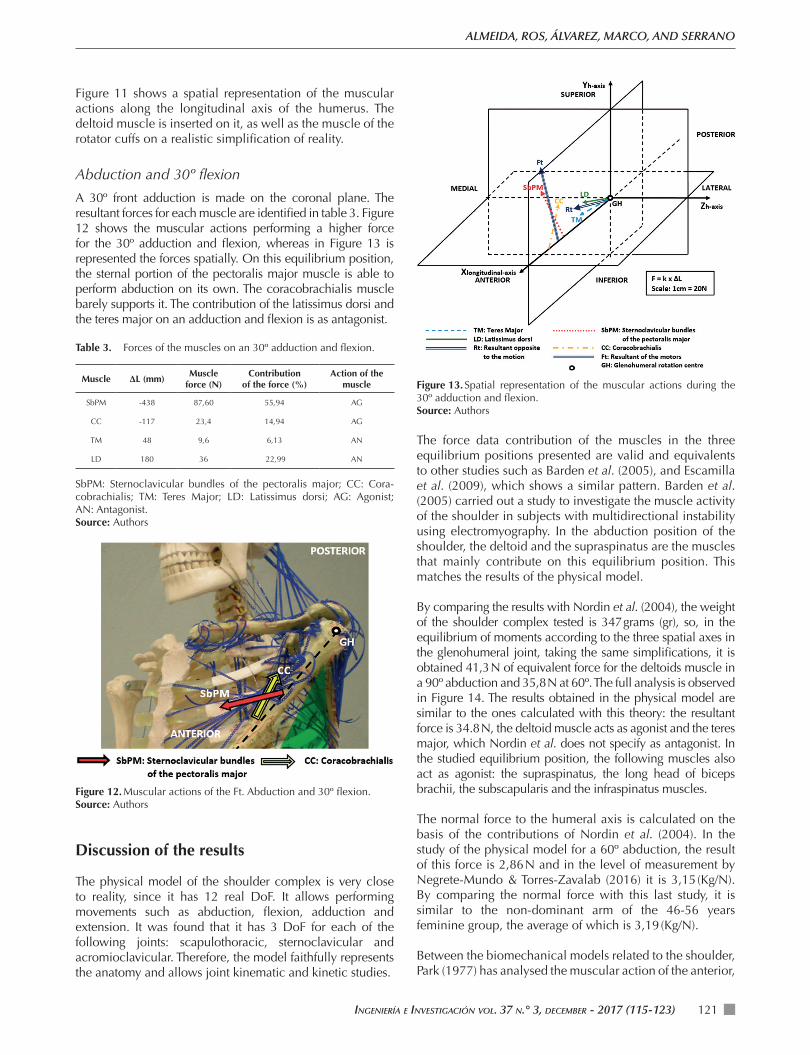
Figure 11. Spatial representation of the forces during the 60º abduction.Source: Authors
INGENIERÍA E INVESTIGACIÓN VOL. 37 N.° 3, DECEMBER - 2017 (115-123) 121
ALMEIDA, ROS, ÁLVAREZ, MARCO, AND SERRANO
Figure 11 shows a spatial representation of the muscular actions along the longitudinal axis of the humerus. The deltoid muscle is inserted on it, as well as the muscle of the rotator cuffs on a realistic simplifi cation of reality.
Abduction and 30º fl exion
A 30º front adduction is made on the coronal plane. The resultant forces for each muscle are identifi ed in table 3. Figure 12 shows the muscular actions performing a higher force for the 30º adduction and fl exion, whereas in Figure 13 is represented the forces spatially. On this equilibrium position, the sternal portion of the pectoralis major muscle is able to perform abduction on its own. The coracobrachialis muscle barely supports it. The contribution of the latissimus dorsi and the teres major on an adduction and fl exion is as antagonist.
Table 3. Forces of the muscles on an 30º adduction and fl exion.
Muscle ΔL (mm)Muscle
force (N)Contribution
of the force (%)Action of the
muscle
SbPM -438 87,60 55,94 AG
CC -117 23,4 14,94 AG
TM 48 9,6 6,13 AN
LD 180 36 22,99 AN
SbPM: Sternoclavicular bundles of the pectoralis major; CC: Cora-cobrachialis; TM: Teres Major; LD: Latissimus dorsi; AG: Agonist; AN: Antagonist. Source: Authors
Figure 12. Muscular actions of the Ft. Abduction and 30º fl exion.Source: Authors
Discussion of the results
The physical model of the shoulder complex is very close to reality, since it has 12 real DoF. It allows performing movements such as abduction, fl exion, adduction and extension. It was found that it has 3 DoF for each of the following joints: scapulothoracic, sternoclavicular and acromioclavicular. Therefore, the model faithfully represents the anatomy and allows joint kinematic and kinetic studies.
Figure 13. Spatial representation of the muscular actions during the 30º adduction and fl exion.Source: Authors
The force data contribution of the muscles in the three equilibrium positions presented are valid and equivalents to other studies such as Barden et al. (2005), and Escamilla et al. (2009), which shows a similar pattern. Barden et al. (2005) carried out a study to investigate the muscle activity of the shoulder in subjects with multidirectional instability using electromyography. In the abduction position of the shoulder, the deltoid and the supraspinatus are the muscles that mainly contribute on this equilibrium position. This matches the results of the physical model.
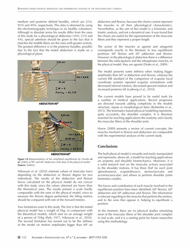
By comparing the results with Nordin et al. (2004), the weight of the shoulder complex tested is 347 grams (gr), so, in the equilibrium of moments according to the three spatial axes in the glenohumeral joint, taking the same simplifi cations, it is obtained 41,3 N of equivalent force for the deltoids muscle in a 90º abduction and 35,8 N at 60º. The full analysis is observed in Figure 14. The results obtained in the physical model are similar to the ones calculated with this theory: the resultant force is 34.8 N, the deltoid muscle acts as agonist and the teres major, which Nordin et al. does not specify as antagonist. In the studied equilibrium position, the following muscles also act as agonist: the supraspinatus, the long head of biceps brachii, the subscapularis and the infraspinatus muscles.
The normal force to the humeral axis is calculated on the basis of the contributions of Nordin et al. (2004). In the study of the physical model for a 60º abduction, the result of this force is 2,86 N and in the level of measurement by Negrete-Mundo & Torres-Zavalab (2016) it is 3,15 (Kg/N). By comparing the normal force with this last study, it is similar to the non-dominant arm of the 46-56 years feminine group, the average of which is 3,19 (Kg/N).
Between the biomechanical models related to the shoulder, Park (1977) has analysed the muscular action of the anterior,
KINEMATICS BASED PHYSICAL MODELLING AND EXPERIMENTAL ANALYSIS OF THE SHOULDER JOINT COMPLEX
INGENIERÍA E INVESTIGACIÓN VOL. 37 N.° 3, DECEMBER - 2017 (115-123)122
medium and posterior deltoid bundles, which are 22 N, 95 N and 49 N, respectively. This data is obtained by using the electromyography technique in six healthy volunteers. Although in absolute terms his results differ from the ones of this study for a physiological abduction (10 N, 21 N and 4 N), special attention should be given to the fact that it matches the middle fi bres are the ones with greater activity. The greatest difference is in the posterior bundles, possibly due to the fact that the tested abduction is made on a physiological plane.
abduction and fl exion, because the chains cannot represent the muscles in all their physiological characteristics. Nevertheless, as the aim of this model is a kinematic and kinetic analysis, and not a dynamical one. It was found that the chains are useful for the representation of the muscular fi bres and they represent a proper length.
The action of the muscles as agonist and antagonist corresponds exactly to the literature in two equilibrium positions: 60º fl exion and 30º adduction and fl exion. However, in the physiological abduction there is a difference between the subscapularis and the infraspinatus muscles, in the physical model, they are agonist (Drake et al., 2009).
The model presents some stiffness when making bigger amplitudes than 60º at abduction and fl exion, whereas the current ISB standard of the comparison of scapular local coordinate systems reported scapular orientations with decreased internal rotation, decreased upward rotation and increased posterior tilt (Ludewig et al., 2010).
The current models have proved to be useful tools for a number of medical applications. Recent progresses are directed towards adding complexity to the models (structure, inputs or morphological data) (Bolsterlee et al., 2013). The kinematics based physical modelling represents, quite accurately, the shoulder complex. It is therefore essential for teaching applications the anatomy and classify the muscular fi bres of the shoulder joint.
Hurov (2009) presents a review of current concepts, the muscles involved in fl exion and abduction are comparable with the experimental analysis of the current study.
Conclusions
The built physical model is versatile and easily manipulated and represents, above all, a model for teaching applications on anatomy and shoulder biomechanics. Moreover, it is a valid research tool on the muscular actions associated to the shoulder motions. It has three DoF for each joint (glenohumeral, scapulothoracic, sternoclavicular and acromioclavicular) and allows to perform shoulder joints kinematics studies.
The forces and contribution of each muscle involved in the equilibrium position have been identifi ed: 60º fl exion, 60º abduction and 30º adduction and fl exion. The information is relevant regarding to the muscles that perform the motion, and to the ones that oppose it, helping to equilibrate a position.
At the moment, there are no physical studies simulating most of the muscular fi bres of the shoulder joint complex in real scale, and it is a starting point for future researches using this methodology.
Figure 14. Representation of the simplifi ed equilibrium by Nordin et al. (2004) at 90º and 60º abduction with data of the physical model.Source: Authors
Nikooyan et al. (2010) estimate values of muscular force depending on the abduction or fl exion degree for two individuals. The results of the abduction and fl exion forces calculated on the physical model do not concur with this study, since the values obtained are lower than the theoretical ones. The results present a scale hardly comparable with the ones of the physical model, since to measure the fl exion degree performed, the lifting motion should be compared with one of the forward motion.
Two limitations exist in this study. The fi rst is that the tested physical model has a weight of 9 kg, in comparison with the theoretical models, which start on an average weight of a person of 70 Kg (Park, 1977; Nikooyan et al., 2010). The second limitation has turned out to be the stiffness of the model on motion amplitudes bigger than 60º on
IngenIería e InvestIgacIón vol. 37 n.° 3, december - 2017 (115-123) 123
ALMEIDA, ROS, ÁLVAREZ, MARCO, AND SERRANO
References
Ahmad, C. S., Dyrszka, M. D., & Kwon, D. H. (2014). Biomechanics of the Shoulder. In G. Milano, & A. Grasso (Eds.), Shoulder Arthroscopy. (pp. 17-30). England: Springer London. DOI:10.1007/978-1-4471-5427-3_2
Barden, J. M., Balyk, R., Raso, V. J., Moreau, M., & Bagnall, K. (2005). Atypical shoulder muscle activation in multidirectional instability. Clinical neurophysiology, 116(8), 1846-1857. DOI:10.1016/j.clinph.2005.04.019
Bolsterlee, B., Veeger, D. H., & Chadwick, E. K. (2013). Clinical applications of musculoskeletal modelling for the shoulder and upper limb. Medical & biological engineering & computing, 51(9), 953-963.
DOI:https://doi.org/10.1007/s11517-013-1099-5
Büchler, P., Ramaniraka, N. A., Rakotomanana, L. R., Iannotti, J. P., & Farron, A. (2002). A finite element model of the shoulder: application to the comparison of normal and osteoarthritic joints. Clinical Biomechanics, 17(9), 630-639. DOI:10.1016/S0268-0033(02)00106-7
Charlton, I. W., & Johnson, G. R. (2006). A model for the prediction of the forces at the glenohumeral joint. Proceedings of the Institution of Mechanical Engineers, Part H: Journal of Engineering in Medicine., 220(8), 801-812. DOI:10.1243/09544119JEIM147
Drake, R., Vogl, A. W., & Mitchell, A. W. (2009). Gray’s Anatomy for Students E-Book. Canada: Elsevier Health Sciences.
Escamilla, R. F., Yamashiro, K., Paulos, L., & Andrews, J. R. (2009). Shoulder muscle activity and function in common shoulder rehabilitation exercises. Sports medicine, 39(8), 663-685. DOI:10.2165/00007256-200939080-00004
Hobbie, R. K., & Roth, B. J. (2015). Intermediate physics for medicine and biology. (Fifth edition ed.). London: Springer Science & Business Media.
DOI:10.1007/978-3-319-12682-1
Hurov, J. (2009). Anatomy and mechanics of the shoulder: review of current concepts. Journal of Hand therapy, 22(4), 328-343. DOI:https://doi.org/10.1016/j.jht.2009.05.002
Jackson, M., Michaud, B., Tétreault, P., & Begon, M. (2012). Improvements in measuring shoulder joint kinematics. Journal of biomechanics, 45(12), 2180-2183. DOI:10.1016/j.jbiomech.2012.05.042
Jago, A. G. (2010). Lifesize Anatomical Human Skeleton Model. Instruction manual. Germany. Retrieved from http://www.jago24.de/en/living/office/lifesize-human-skeleton-anatomy-model.html?listtype=search&searchparam=skeleton#head-techdata.
Kapandji, A. I. (2012). Fisiología articular. Tomo 1. Miembro superior. Sexta Edición.
Klopčar, N., Tomšič, M., & Lenarčič, J. (2007). A kinematic model of the shoulder complex to evaluate the arm-reachable workspace. Journal of biomechanics, 40(1), 86-91. DOI:10.1016/j.jbiomech.2005.11.010
Limb, D. (2014). Biomechanics of the Shoulder. In D. Limb, & G. Bentley (Ed.), European Surgical Orthopaedics and Traumatology. (pp. 847-864). Germany: Springer Berlin Heidelberg. DOI:10.1007/978-3-642-34746-7_58
Liu, Y. (2017). Silicone Dispersions. Florida: CRC Press.
Ludewig, P. M., Hassett, D. R., LaPrade, R. F., Camargo, P. R., & Braman, J. P. (2010). Comparison of scapular local coordinate systems. Clinical Biomechanics, 25(5), 415-421. DOI:http://dx.doi.org/10.1016/j.clinbiomech.2010.01.015
Ludewig, P. M., Phadke, V., Braman, J. P., Hassett, D. R., Cieminski, C. J., & LaPrade, R. F. (2009). Motion of the shoulder complex during multiplanar humeral elevation. The Journal of Bone and Joint Surgery. American volume., 91(2), 378-389. DOI:10.2106/JBJS.G.01483
Murray, I. A., & Johnson, G. R. (2004). A study of the external forces and moments at the shoulder and elbow while performing every day tasks. Clinical biomechanics, 19(6), 586-594. DOI:10.1016/j.clinbiomech.2004.03.004
Negrete-Mundo, E., & Torres-Zavalab, A. (2016). Medición de la fuerza de abducción del hombro en individuos sanos. Rev Med Inst Mex Seguro Soc, 54(3), S248-53.
Nikooyan, A. A., Veeger, H. E., Westerhoff, P., Graichen, F., Bergmann, G., & Van der Helm, F. C. (2010). Validation of the Delft Shoulder and Elbow Model using in-vivo glenohumeral joint contact forces. (Vol. 43). Journal of biomechanics. DOI:10.1016/j.jbiomech.2010.06.015
Nordin, M., Frankel, V. H., & Forssén, K. (2004). Biomecánica básica del sistema musculoesquelético. (Primera Edición ed.). España: McGraw-Hill. Interamericana.
Park, Y. P. (1977). A mathematical analysis of the musculo-skeletal system of the human shoulder joint (Doctoral dissertation). Texas: Texas Tech University. Retrieved from http://hdl.handle.net/2346/14265
Phadke, V., Braman, J. P., LaPrade, R. F., & Ludewig, P. M. (2011). Comparison of glenohumeral motion using different rotation sequences. Journal of biomechanics, 44(4), 700-705. DOI:https://doi.org/10.1016/j.jbiomech.2010.10.042
Poppen, N. K., & Walker, P. S. (1978). Forces at the glenohumeral joint in abduction. Clinical Orthopaedics and Related Research, 135, 165-170.
Rull, I. M., & Cunillera, M. P. (2005). Biomecánica clínica de los tejidos y las articulaciones del aparato locomotor. España: Elsevier España.
Van der Helm, F. C., & Veenbaas, R. (1991). Modelling the mechanical effect of muscles with large attachment sites: application to the shoulder mechanism. Journal of biomechanics, 24(12), 1151-1163.
DOI:http://dx.doi.org/10.1016/0021-9290(91)90007-A
Wang, M., & Yu, C. (2004). Silicone rubber: an alternative for repair of articular cartilage defects. Knee Surgery, Sports Traumatology, Arthroscopy, 12(6), 556-561.
DOI:https://doi.org/10.1007/s00167-003-0447-7
Wu, G., Van der Helm, F. C., Veeger, H. D., Makhsous, M., Van Roy, P., Anglin, C., & Werner, F. W. (2005). ISB recommendation on definitions of joint coordinate systems of various joints for the reporting of human joint motion—Part II: shoulder, elbow, wrist and hand. Journal of biomechanics, 38(5), 981-992.
DOI:https://doi.org/10.1016/j.jbiomech.2004.05.042