Embed Size (px)
Citation preview
KIP 770 User Manual Version A.0
(1)
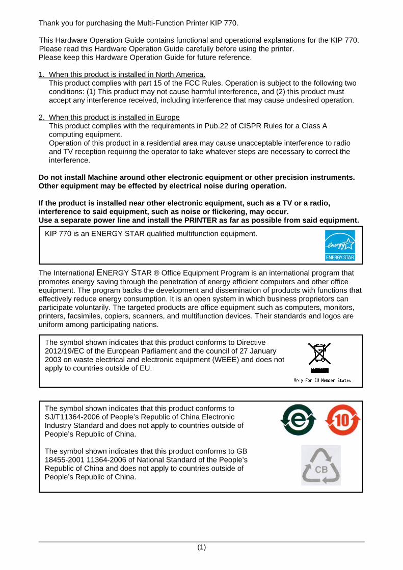
Thank you for purchasing the Multi-Function Printer KIP 770. This Hardware Operation Guide contains functional and operational explanations for the KIP 770. Please read this Hardware Operation Guide carefully before using the printer. Please keep this Hardware Operation Guide for future reference. 1. When this product is installed in North America. This product complies with part 15 of the FCC Rules. Operation is subject to the following two conditions: (1) This product may not cause harmful interference, and (2) this product must accept any interference received, including interference that may cause undesired operation. 2. When this product is installed in Europe This product complies with the requirements in Pub.22 of CISPR Rules for a Class A computing equipment. Operation of this product in a residential area may cause unacceptable interference to radio and TV reception requiring the operator to take whatever steps are necessary to correct the interference. Do not install Machine around other electronic equipment or other precision instruments. Other equipment may be effected by electrical noise during operation. If the product is installed near other electronic equipment, such as a TV or a radio, interference to said equipment, such as noise or flickering, may occur. Use a separate power line and install the PRINTER as far as possible from said equipment. The International ENERGY STAR ® Office Equipment Program is an international program that promotes energy saving through the penetration of energy efficient computers and other office equipment. The program backs the development and dissemination of products with functions that effectively reduce energy consumption. It is an open system in which business proprietors can participate voluntarily. The targeted products are office equipment such as computers, monitors, printers, facsimiles, copiers, scanners, and multifunction devices. Their standards and logos are uniform among participating nations.
The symbol shown indicates that this product conforms to Directive 2012/19/EC of the European Parliament and the council of 27 January 2003 on waste electrical and electronic equipment (WEEE) and does not apply to countries outside of EU.
KIP 770 is an ENERGY STAR qualified multifunction equipment.
The symbol shown indicates that this product conforms to SJ/T11364-2006 of People’s Republic of China Electronic Industry Standard and does not apply to countries outside of People’s Republic of China. The symbol shown indicates that this product conforms to GB 18455-2001 11364-2006 of National Standard of the People’s Republic of China and does not apply to countries outside of People’s Republic of China.
(2)
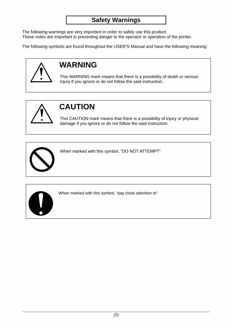
Safety Warnings The following warnings are very important in order to safely use this product. These notes are important in preventing danger to the operator or operation of the printer. The following symbols are found throughout the USER’S Manual and have the following meaning:
WARNING This WARNING mark means that there is a possibility of death or serious injury if you ignore or do not follow the said instruction.
CAUTION This CAUTION mark means that there is a possibility of injury or physical damage if you ignore or do not follow the said instruction.
When marked with this symbol, “DO NOT ATTEMPT”
When marked with this symbol, “pay close attention to”
(3)
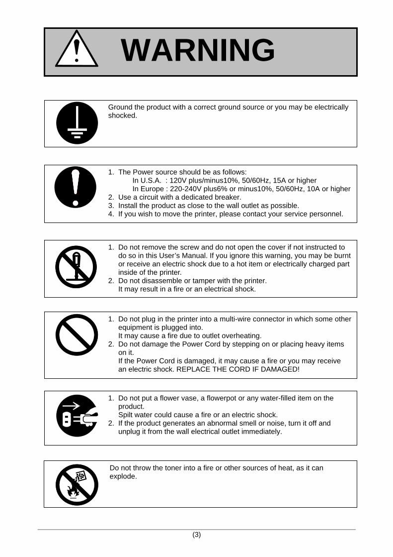
WARNING
1. The Power source should be as follows: In U.S.A. : 120V plus/minus10%, 50/60Hz, 15A or higher In Europe : 220-240V plus6% or minus10%, 50/60Hz, 10A or higher 2. Use a circuit with a dedicated breaker. 3. Install the product as close to the wall outlet as possible. 4. If you wish to move the printer, please contact your service personnel.
Ground the product with a correct ground source or you may be electrically shocked.
1. Do not plug in the printer into a multi-wire connector in which some other equipment is plugged into. It may cause a fire due to outlet overheating. 2. Do not damage the Power Cord by stepping on or placing heavy items on it. If the Power Cord is damaged, it may cause a fire or you may receive an electric shock. REPLACE THE CORD IF DAMAGED!
1. Do not put a flower vase, a flowerpot or any water-filled item on the product. Spilt water could cause a fire or an electric shock. 2. If the product generates an abnormal smell or noise, turn it off and unplug it from the wall electrical outlet immediately.
1. Do not remove the screw and do not open the cover if not instructed to do so in this User’s Manual. If you ignore this warning, you may be burnt or receive an electric shock due to a hot item or electrically charged part inside of the printer. 2. Do not disassemble or tamper with the printer. It may result in a fire or an electrical shock.
Do not throw the toner into a fire or other sources of heat, as it can explode.
(4)
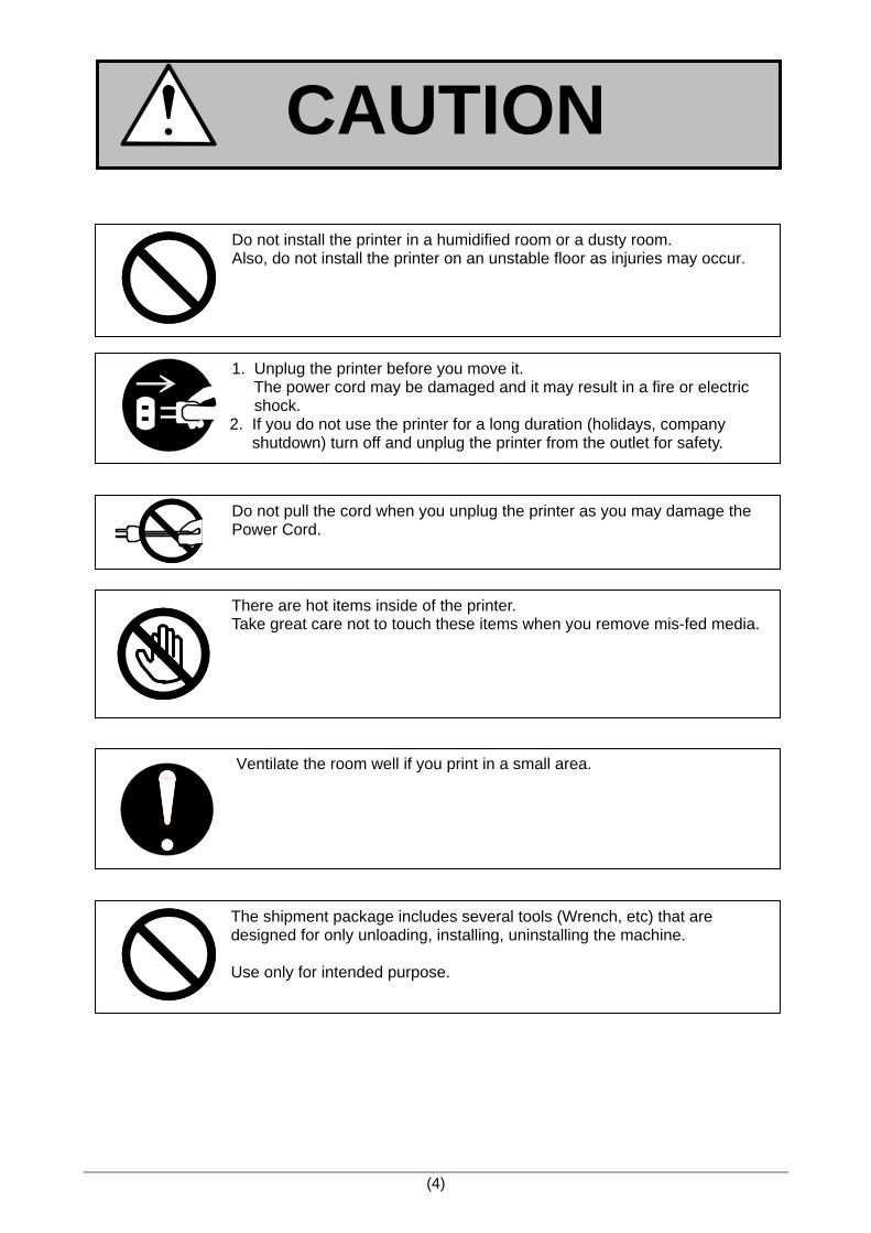
CAUTION
There are hot items inside of the printer. Take great care not to touch these items when you remove mis-fed media.
Do not pull the cord when you unplug the printer as you may damage the Power Cord.
Do not install the printer in a humidified room or a dusty room. Also, do not install the printer on an unstable floor as injuries may occur.
1. Unplug the printer before you move it. The power cord may be damaged and it may result in a fire or electric shock.
2. If you do not use the printer for a long duration (holidays, company shutdown) turn off and unplug the printer from the outlet for safety.
Ventilate the room well if you print in a small area.
The shipment package includes several tools (Wrench, etc) that are designed for only unloading, installing, uninstalling the machine. Use only for intended purpose.
(5)
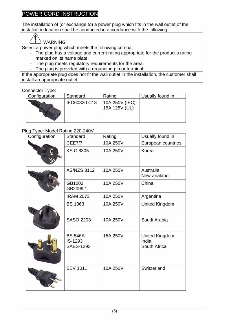
POWER CORD INSTRUCTION The installation of (or exchange to) a power plug which fits in the wall outlet of the installation location shall be conducted in accordance with the following:
WARNING Select a power plug which meets the following criteria;
- The plug has a voltage and current rating appropriate for the product’s rating marked on its name plate.
- The plug meets regulatory requirements for the area. - The plug is provided with a grounding pin or terminal.
If the appropriate plug does not fit the wall outlet in the installation, the customer shall install an appropriate outlet. Connector Type:
Configuration Standard Rating Usually found in
IEC60320:C13 10A 250V (IEC) 15A 125V (UL)
Plug Type: Model Rating 220-240V
Configuration Standard Rating Usually found in
CEE7/7 10A 250V European countries
KS C 8305 10A 250V Korea
AS/NZS 3112 10A 250V Australia New Zealand
GB1002 GB2099.1
10A 250V China
IRAM 2073 10A 250V Argentina
BS 1363 10A 250V United Kingdom
SASO 2203 10A 250V Saudi Arabia
BS 546A IS-1293 SABS-1293
15A 250V United Kingdom India South Africa
SEV 1011 10A 250V Switzerland
Chapter 1 Before Use 1-1
Chapter 1
Before Use Page 1. 1 Installation Requirements 1- 2 1. 2 Originals Prohibited from Duplication 1- 3 1. 3 Features 1- 4 1. 4 Specifications 1- 5
1. 4. 1 General 1- 5 1. 4. 2 Printer part 1- 6 1. 4. 3 Scanner part 1- 8
1. 5 Appearance 1- 9
1. 5. 1 Front view 1- 9 1. 5. 2 Rear view 1-10
1. 6 Specifications for the Scan Original 1-11 1. 7 Specifications for the Printing Paper 1-14 1. 7. 1 Papers not available to use 1-14 1. 7. 2 Keeping the paper in the custody 1-15 1. 7. 3 Treatment against environmental condition 1-16
Chapter 1 Before Use 1-2
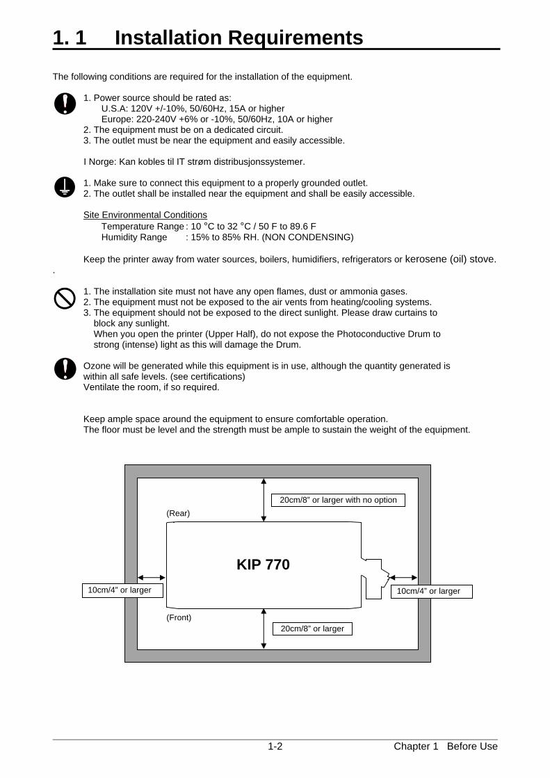
1. 1 Installation Requirements The following conditions are required for the installation of the equipment. 1. Power source should be rated as: U.S.A: 120V +/-10%, 50/60Hz, 15A or higher Europe: 220-240V +6% or -10%, 50/60Hz, 10A or higher 2. The equipment must be on a dedicated circuit. 3. The outlet must be near the equipment and easily accessible.
I Norge: Kan kobles til IT strøm distribusjonssystemer. 1. Make sure to connect this equipment to a properly grounded outlet. 2. The outlet shall be installed near the equipment and shall be easily accessible. Site Environmental Conditions Temperature Range : 10 °C to 32 °C / 50 F to 89.6 F Humidity Range : 15% to 85% RH. (NON CONDENSING) Keep the printer away from water sources, boilers, humidifiers, refrigerators or kerosene (oil) stove. . 1. The installation site must not have any open flames, dust or ammonia gases. 2. The equipment must not be exposed to the air vents from heating/cooling systems. 3. The equipment should not be exposed to the direct sunlight. Please draw curtains to block any sunlight. When you open the printer (Upper Half), do not expose the Photoconductive Drum to strong (intense) light as this will damage the Drum. Ozone will be generated while this equipment is in use, although the quantity generated is within all safe levels. (see certifications) Ventilate the room, if so required. Keep ample space around the equipment to ensure comfortable operation. The floor must be level and the strength must be ample to sustain the weight of the equipment.
KIP 770
20cm/8” or larger
20cm/8” or larger with no option
10cm/4” or larger 10cm/4” or larger
(Front)
(Rear)
Chapter 1 Before Use 1-3
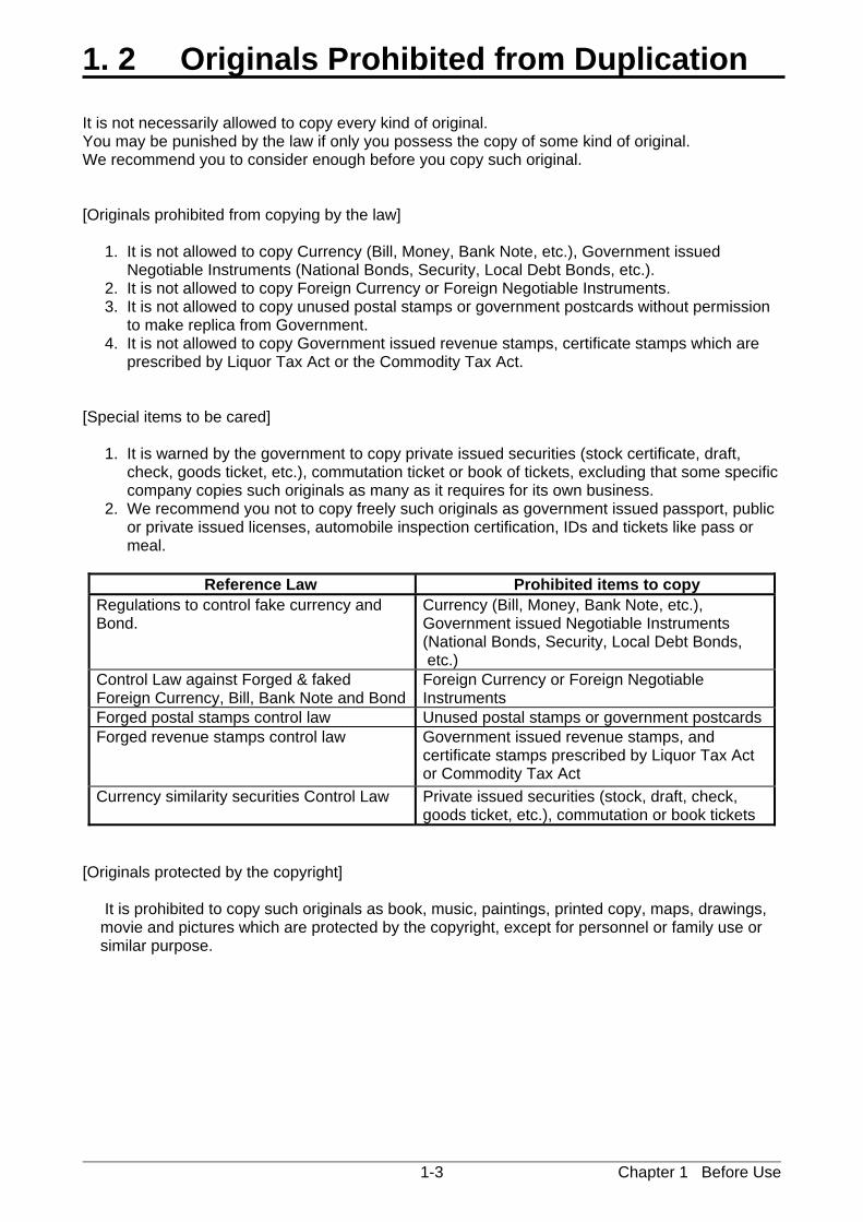
1. 2 Originals Prohibited from Duplication It is not necessarily allowed to copy every kind of original. You may be punished by the law if only you possess the copy of some kind of original. We recommend you to consider enough before you copy such original. [Originals prohibited from copying by the law] 1. It is not allowed to copy Currency (Bill, Money, Bank Note, etc.), Government issued Negotiable Instruments (National Bonds, Security, Local Debt Bonds, etc.). 2. It is not allowed to copy Foreign Currency or Foreign Negotiable Instruments. 3. It is not allowed to copy unused postal stamps or government postcards without permission to make replica from Government. 4. It is not allowed to copy Government issued revenue stamps, certificate stamps which are prescribed by Liquor Tax Act or the Commodity Tax Act. [Special items to be cared] 1. It is warned by the government to copy private issued securities (stock certificate, draft, check, goods ticket, etc.), commutation ticket or book of tickets, excluding that some specific company copies such originals as many as it requires for its own business. 2. We recommend you not to copy freely such originals as government issued passport, public or private issued licenses, automobile inspection certification, IDs and tickets like pass or meal.
Reference Law Prohibited items to copy Regulations to control fake currency and Bond.
Currency (Bill, Money, Bank Note, etc.), Government issued Negotiable Instruments (National Bonds, Security, Local Debt Bonds, etc.)
Control Law against Forged & faked Foreign Currency, Bill, Bank Note and Bond
Foreign Currency or Foreign Negotiable Instruments
Forged postal stamps control law Unused postal stamps or government postcardsForged revenue stamps control law Government issued revenue stamps, and
certificate stamps prescribed by Liquor Tax Act or Commodity Tax Act
Currency similarity securities Control Law Private issued securities (stock, draft, check, goods ticket, etc.), commutation or book tickets
[Originals protected by the copyright] It is prohibited to copy such originals as book, music, paintings, printed copy, maps, drawings, movie and pictures which are protected by the copyright, except for personnel or family use or similar purpose.
Chapter 1 Before Use 1-4
1. 3 Features (1) KIP 770 is a Multi-Function Printer for scan, copy and print large format documents. Some of
these features may be optional. (2) Front loading - front delivery structure saves the installation space. (3) Various media source; roll media feeding (1 roll), cut sheet manual feeding, Paper Tray multiple
cut sheet feeder (option). (4) A dedicated printer stand offers easy print handling with the print basket. The KIP 770 is also
suitable for your office layout as a desktop MFP. (5) The operation speed is 40mm/s (2.9 D landscape / 2.8 A1 landscape per minute). (6) The maximum print width is 914mm / 36” wide, and the minimum one is 210mm or 8.5”.
The maximum print length is 2,400mm (for A0 / 36” wide media), and the minimum one is 297mm or 11”.
(7) Up to 600dpi print resolutions with an enhanced scanning system produces the highest quality
images controlled by an advanced KIP Image Process System. (8) The combination of KIP Contact Development System and mono-component minute toner can
produce a high definition line, distinctive grayscale and consistent solid black. The KIP HDP process generates no Waste Toner.
(9) Easy access to USB port allows users to provide efficient productivity by using “File to Print” /
“Scan to USB” (option). (10) KIP 770 adopts 12.1 inch screen for the UI, wider than 8.5 for our old products.
The capacitive multi-touch screen offers smooth, various and intuitive user operation that a pressure sensing device lacks.
Chapter 1 Before Use 1-5
1. 4 Specifications
1. 4. 1 General
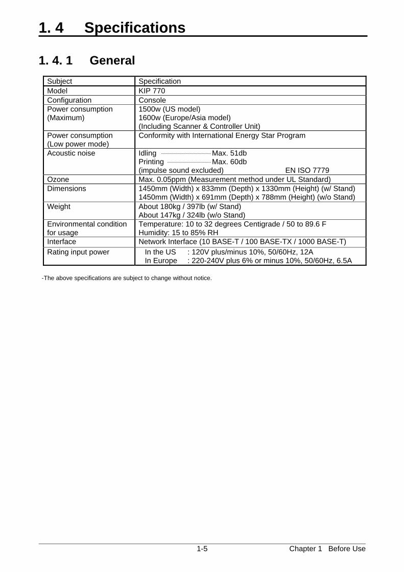
Subject Specification Model KIP 770 Configuration Console Power consumption (Maximum)
1500w (US model) 1600w (Europe/Asia model) (Including Scanner & Controller Unit)
Power consumption (Low power mode)
Conformity with International Energy Star Program
Acoustic noise Idling Max. 51db Printing Max. 60db (impulse sound excluded) EN ISO 7779
Ozone Max. 0.05ppm (Measurement method under UL Standard) Dimensions 1450mm (Width) x 833mm (Depth) x 1330mm (Height) (w/ Stand)
1450mm (Width) x 691mm (Depth) x 788mm (Height) (w/o Stand) Weight About 180kg / 397lb (w/ Stand)
About 147kg / 324lb (w/o Stand) Environmental condition for usage
Temperature: 10 to 32 degrees Centigrade / 50 to 89.6 F Humidity: 15 to 85% RH
Interface Network Interface (10 BASE-T / 100 BASE-TX / 1000 BASE-T) Rating input power In the US : 120V plus/minus 10%, 50/60Hz, 12A
In Europe : 220-240V plus 6% or minus 10%, 50/60Hz, 6.5A -The above specifications are subject to change without notice.
Chapter 1 Before Use 1-6
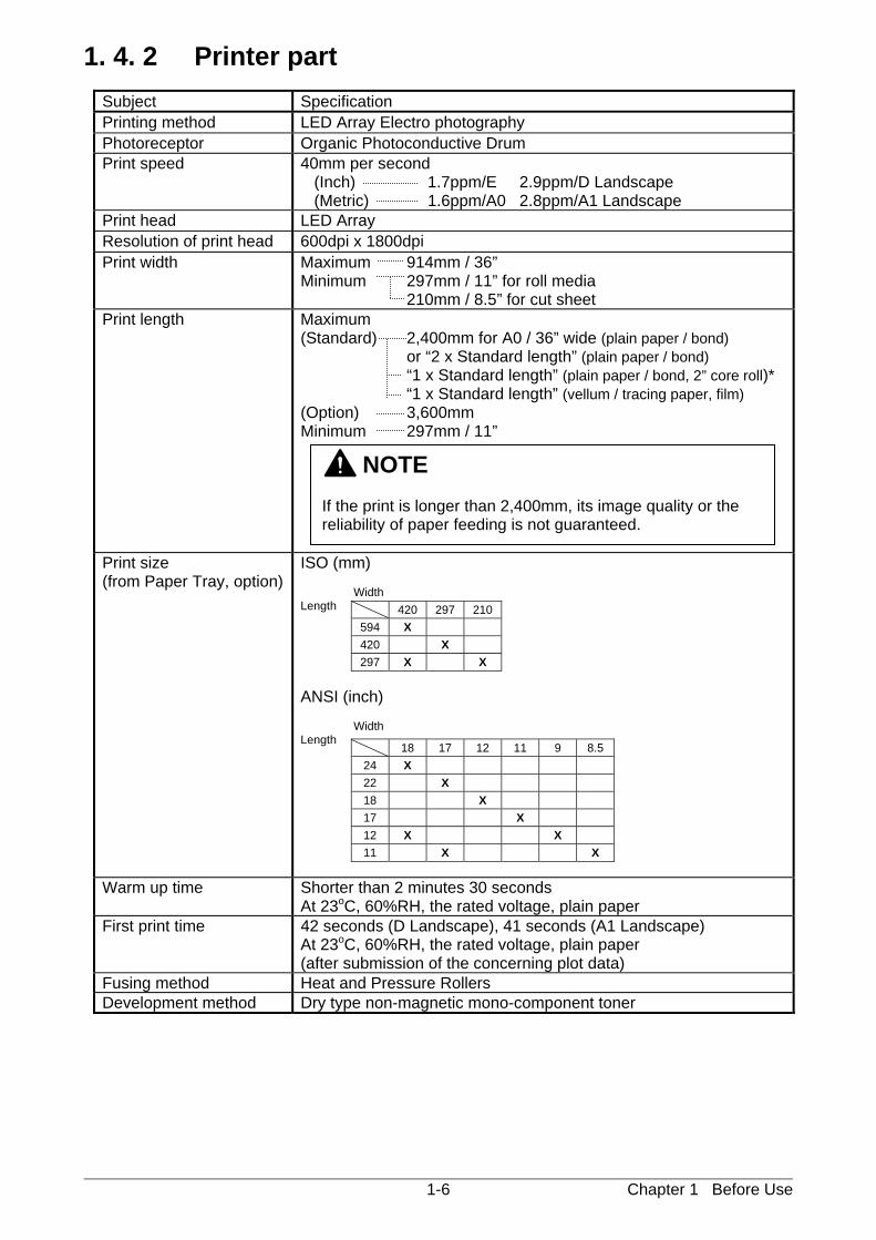
1. 4. 2 Printer part
Subject Specification Printing method LED Array Electro photography Photoreceptor Organic Photoconductive Drum Print speed 40mm per second
(Inch) 1.7ppm/E 2.9ppm/D Landscape (Metric) 1.6ppm/A0 2.8ppm/A1 Landscape
Print head LED Array Resolution of print head 600dpi x 1800dpi Print width Maximum 914mm / 36”
Minimum 297mm / 11” for roll media 210mm / 8.5” for cut sheet
Print length Maximum (Standard) 2,400mm for A0 / 36” wide (plain paper / bond) or “2 x Standard length” (plain paper / bond) “1 x Standard length” (plain paper / bond, 2” core roll)* “1 x Standard length” (vellum / tracing paper, film) (Option) 3,600mm Minimum 297mm / 11”
Print size (from Paper Tray, option)
ISO (mm) Width Length ANSI (inch) Width Length
Warm up time Shorter than 2 minutes 30 seconds At 23oC, 60%RH, the rated voltage, plain paper
First print time 42 seconds (D Landscape), 41 seconds (A1 Landscape) At 23oC, 60%RH, the rated voltage, plain paper (after submission of the concerning plot data)
Fusing method Heat and Pressure Rollers Development method Dry type non-magnetic mono-component toner
NOTE If the print is longer than 2,400mm, its image quality or the reliability of paper feeding is not guaranteed.
420 297 210594 X 420 X 297 X X
18 17 12 11 9 8.524 X 22 X 18 X 17 X 12 X X 11 X X
Chapter 1 Before Use 1-7
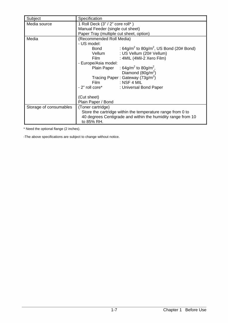
Subject Specification Media source 1 Roll Deck (3” / 2” core roll* )
Manual Feeder (single cut sheet) Paper Tray (multiple cut sheet, option)
Media (Recommended Roll Media) - US model: Bond : 64g/m2 to 80g/m2, US Bond (20# Bond) Vellum : US Vellum (20# Vellum) Film : 4MIL (4Mil-2 Xero Film) - Europe/Asia model: Plain Paper : 64g/m2 to 80g/m2, Diamond (80g/m2) Tracing Paper : Gateway (73g/m2) Film : NSF 4 MIL - 2” roll core* : Universal Bond Paper (Cut sheet) Plain Paper / Bond
Storage of consumables (Toner cartridge) Store the cartridge within the temperature range from 0 to 40 degrees Centigrade and within the humidity range from 10 to 85% RH.
* Need the optional flange (2 inches). -The above specifications are subject to change without notice.
Chapter 1 Before Use 1-8
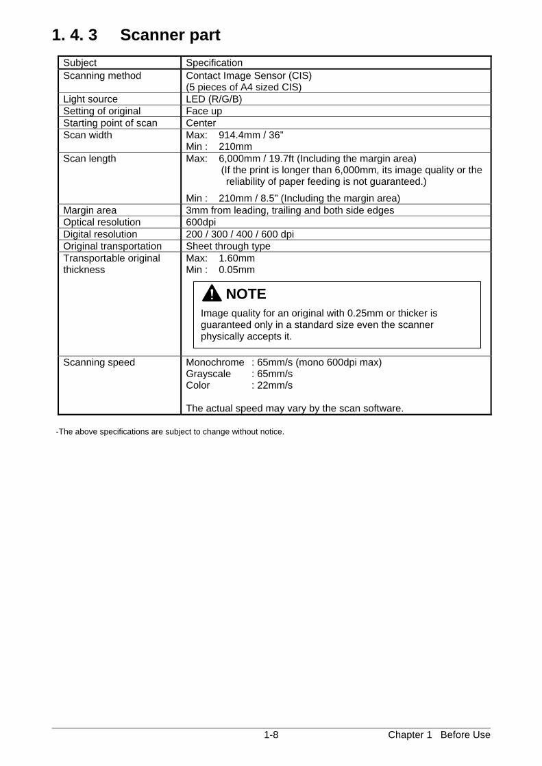
1. 4. 3 Scanner part
Subject Specification Scanning method Contact Image Sensor (CIS)
(5 pieces of A4 sized CIS) Light source LED (R/G/B) Setting of original Face up Starting point of scan Center Scan width Max: 914.4mm / 36”
Min : 210mm Scan length Max: 6,000mm / 19.7ft (Including the margin area)
(If the print is longer than 6,000mm, its image quality or the reliability of paper feeding is not guaranteed.)
Min : 210mm / 8.5” (Including the margin area) Margin area 3mm from leading, trailing and both side edges Optical resolution 600dpi Digital resolution 200 / 300 / 400 / 600 dpi Original transportation Sheet through type Transportable original thickness
Max: 1.60mm Min : 0.05mm
Scanning speed Monochrome : 65mm/s (mono 600dpi max) Grayscale : 65mm/s Color : 22mm/s The actual speed may vary by the scan software.
-The above specifications are subject to change without notice.
NOTE
Image quality for an original with 0.25mm or thicker is guaranteed only in a standard size even the scanner physically accepts it.
Chapter 1 Before Use 1-9
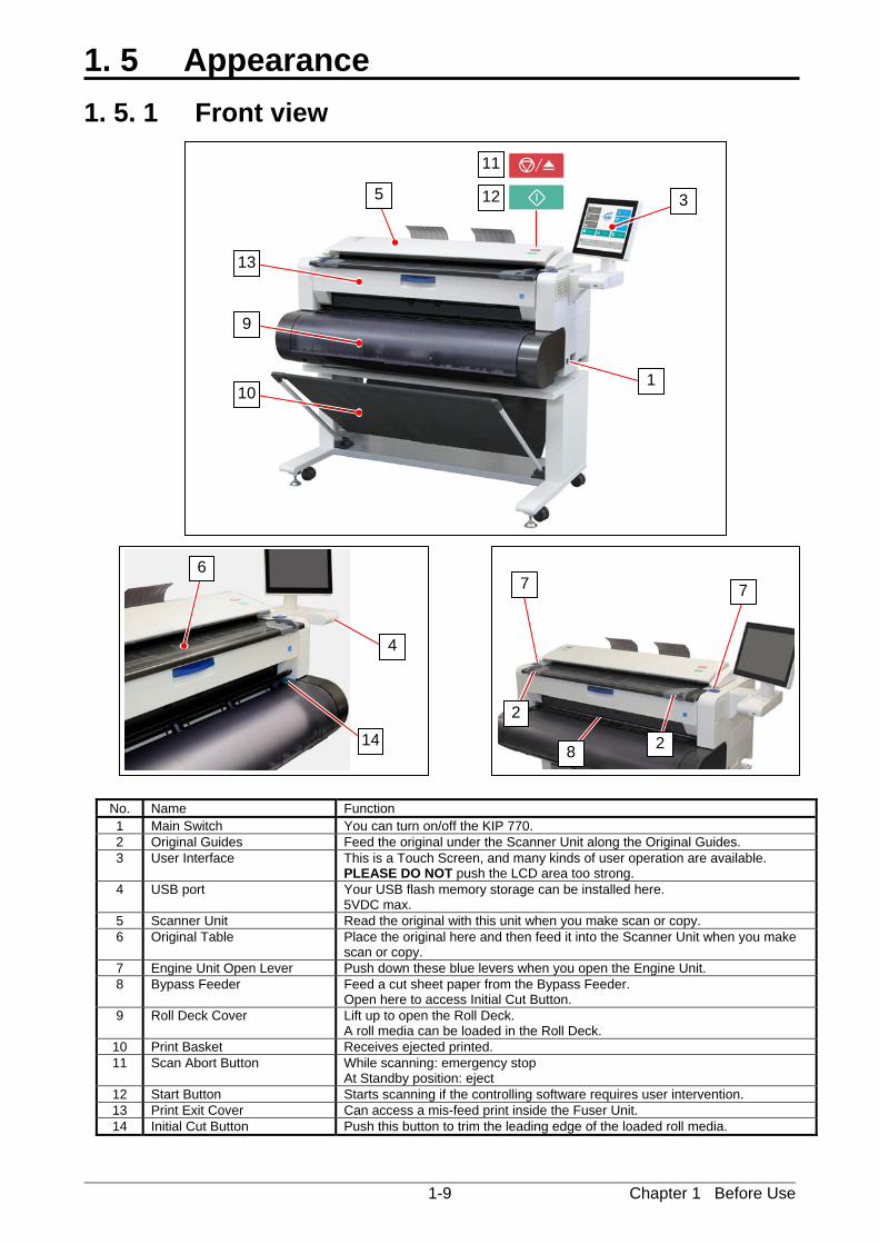
1. 5 Appearance
1. 5. 1 Front view
6
14
4
7 7
2
2
8
No. Name Function 1 Main Switch You can turn on/off the KIP 770. 2 Original Guides Feed the original under the Scanner Unit along the Original Guides. 3 User Interface This is a Touch Screen, and many kinds of user operation are available.
PLEASE DO NOT push the LCD area too strong. 4 USB port Your USB flash memory storage can be installed here.
5VDC max. 5 Scanner Unit Read the original with this unit when you make scan or copy. 6 Original Table Place the original here and then feed it into the Scanner Unit when you make
scan or copy. 7 Engine Unit Open Lever Push down these blue levers when you open the Engine Unit. 8 Bypass Feeder Feed a cut sheet paper from the Bypass Feeder.
Open here to access Initial Cut Button. 9 Roll Deck Cover Lift up to open the Roll Deck.
A roll media can be loaded in the Roll Deck. 10 Print Basket Receives ejected printed. 11 Scan Abort Button While scanning: emergency stop
At Standby position: eject 12 Start Button Starts scanning if the controlling software requires user intervention. 13 Print Exit Cover Can access a mis-feed print inside the Fuser Unit. 14 Initial Cut Button Push this button to trim the leading edge of the loaded roll media.
3 5
13
9
10 1
11
12
Chapter 1 Before Use 1-10
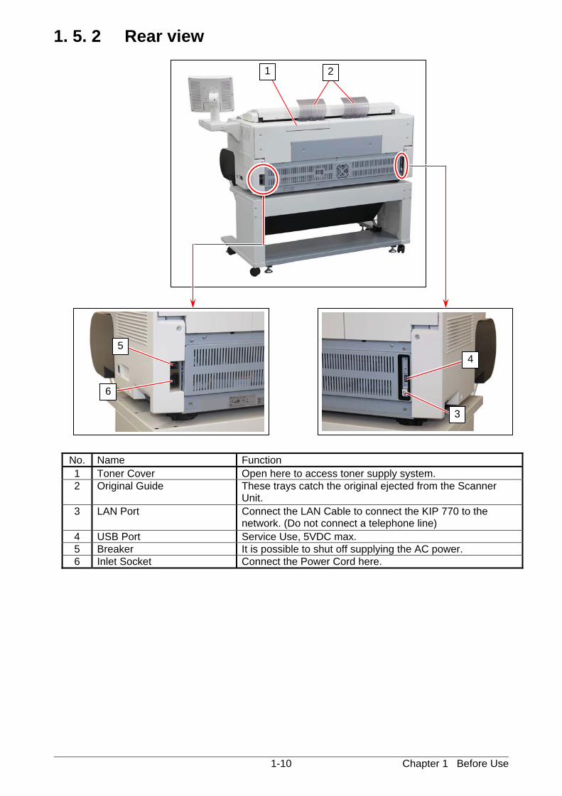
1. 5. 2 Rear view 7: behind
No. Name Function 1 Toner Cover Open here to access toner supply system. 2 Original Guide These trays catch the original ejected from the Scanner
Unit. 3 LAN Port Connect the LAN Cable to connect the KIP 770 to the
network. (Do not connect a telephone line) 4 USB Port Service Use, 5VDC max. 5 Breaker It is possible to shut off supplying the AC power. 6 Inlet Socket Connect the Power Cord here.
5
6
3
4
21
Chapter 1 Before Use 1-11
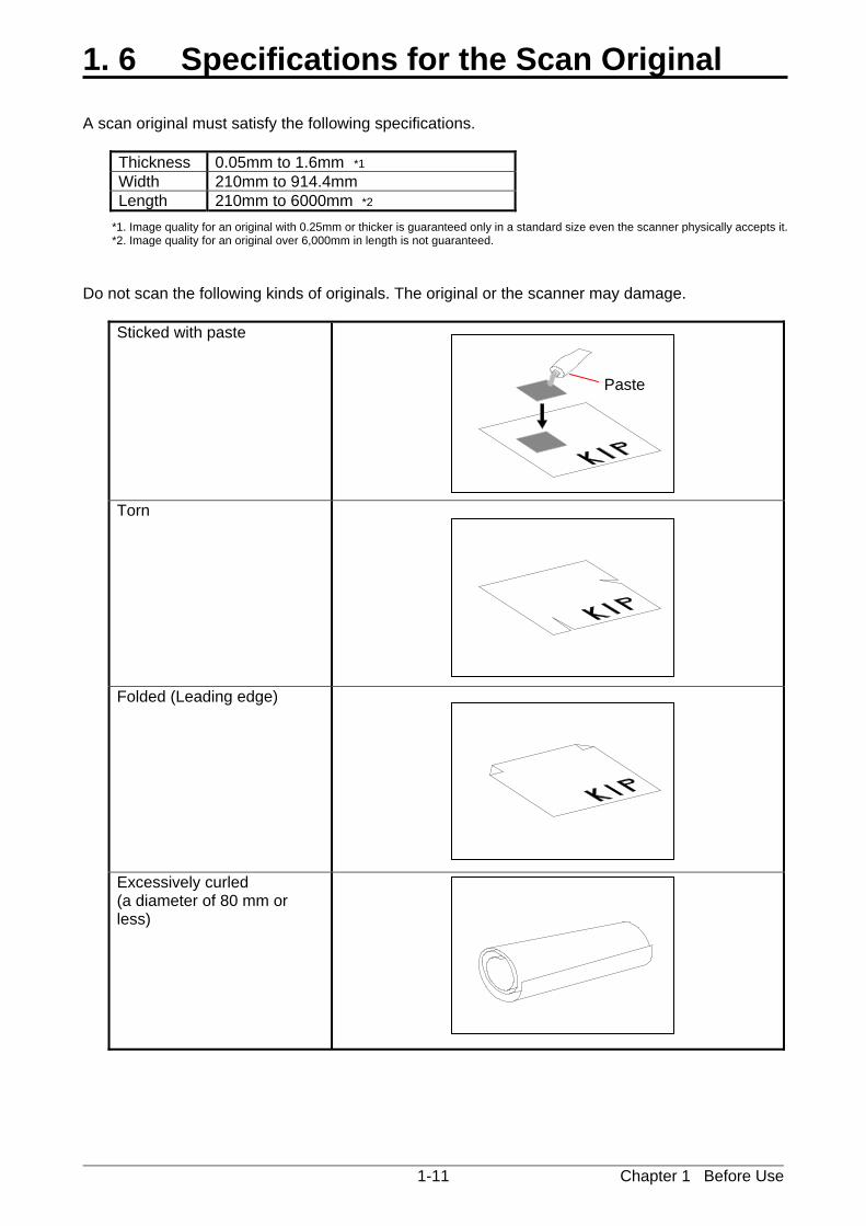
1. 6 Specifications for the Scan Original A scan original must satisfy the following specifications.
Thickness 0.05mm to 1.6mm *1 Width 210mm to 914.4mm Length 210mm to 6000mm *2
*1. Image quality for an original with 0.25mm or thicker is guaranteed only in a standard size even the scanner physically accepts it. *2. Image quality for an original over 6,000mm in length is not guaranteed.
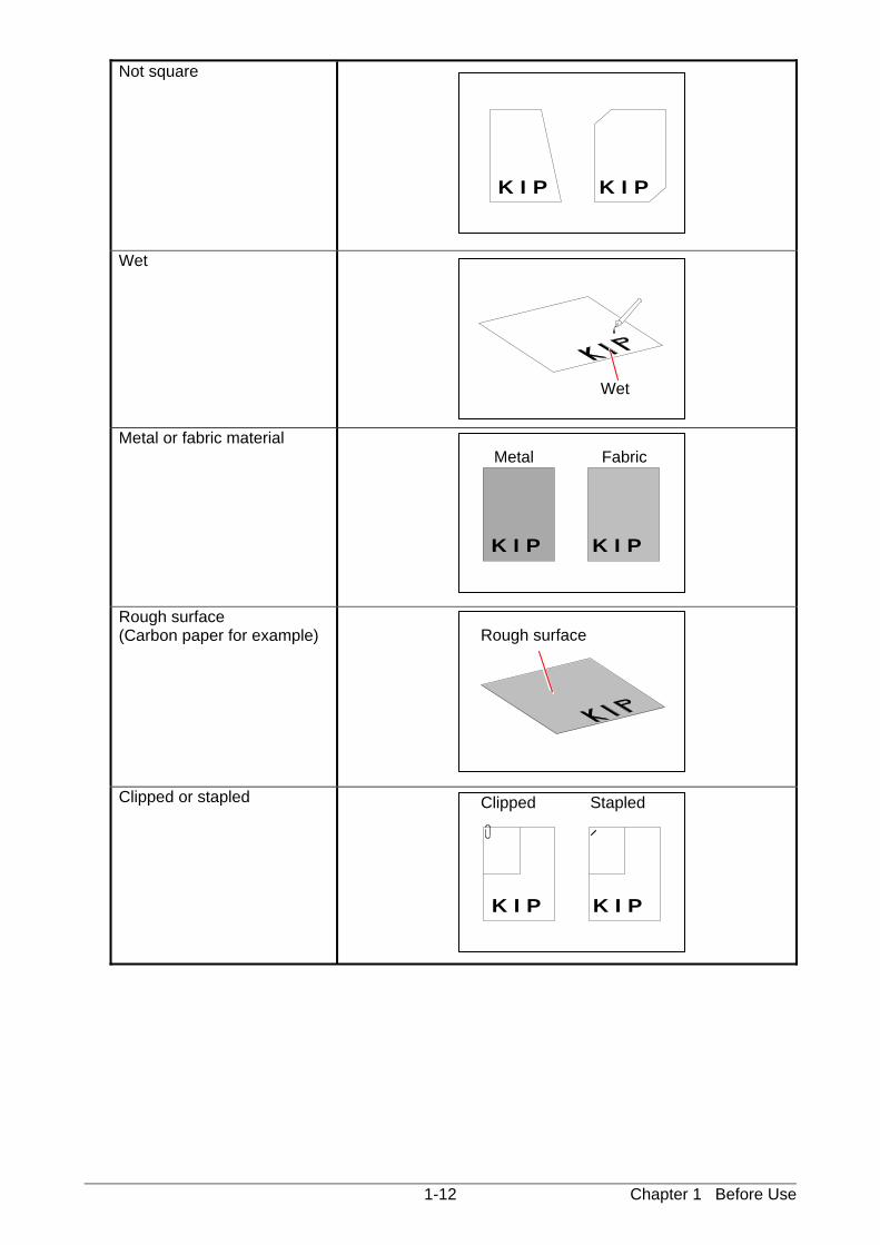
Do not scan the following kinds of originals. The original or the scanner may damage.
Sticked with paste
Torn
Folded (Leading edge)
Excessively curled (a diameter of 80 mm or less)
Paste
Chapter 1 Before Use 1-12
Not square
Wet
Metal or fabric material
Rough surface (Carbon paper for example)
Clipped or stapled
K I P K I P
K I P K I P
K I P K I P
Wet
Metal Fabric
Clipped Stapled
Rough surface
Chapter 1 Before Use 1-13
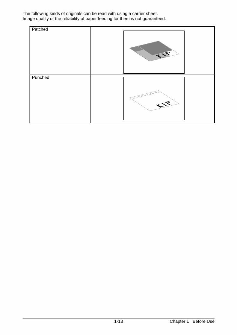
The following kinds of originals can be read with using a carrier sheet. Image quality or the reliability of paper feeding for them is not guaranteed.
Patched
Punched
Chapter 1 Before Use 1-14
1. 7 Specifications for the Printing Paper
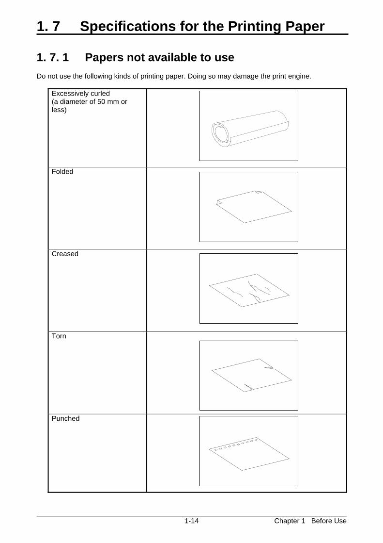
1. 7. 1 Papers not available to use Do not use the following kinds of printing paper. Doing so may damage the print engine.
Excessively curled (a diameter of 50 mm or less)
Folded
Creased
Torn
Punched
Chapter 1 Before Use 1-15
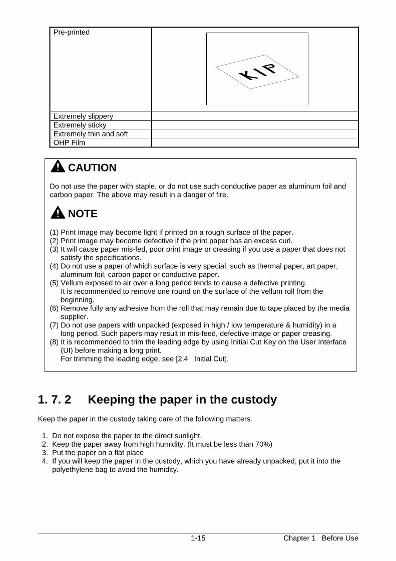
Pre-printed
Extremely slippery Extremely sticky Extremely thin and soft OHP Film
1. 7. 2 Keeping the paper in the custody Keep the paper in the custody taking care of the following matters. 1. Do not expose the paper to the direct sunlight. 2. Keep the paper away from high humidity. (It must be less than 70%) 3. Put the paper on a flat place 4. If you will keep the paper in the custody, which you have already unpacked, put it into the polyethylene bag to avoid the humidity.
CAUTION Do not use the paper with staple, or do not use such conductive paper as aluminum foil and carbon paper. The above may result in a danger of fire. NOTE (1) Print image may become light if printed on a rough surface of the paper. (2) Print image may become defective if the print paper has an excess curl. (3) It will cause paper mis-fed, poor print image or creasing if you use a paper that does not
satisfy the specifications. (4) Do not use a paper of which surface is very special, such as thermal paper, art paper,
aluminum foil, carbon paper or conductive paper. (5) Vellum exposed to air over a long period tends to cause a defective printing.
It is recommended to remove one round on the surface of the vellum roll from the beginning.
(6) Remove fully any adhesive from the roll that may remain due to tape placed by the media supplier.
(7) Do not use papers with unpacked (exposed in high / low temperature & humidity) in a long period. Such papers may result in mis-feed, defective image or paper creasing.
(8) It is recommended to trim the leading edge by using Initial Cut Key on the User Interface (UI) before making a long print. For trimming the leading edge, see [2.4 Initial Cut].
Chapter 1 Before Use 1-16
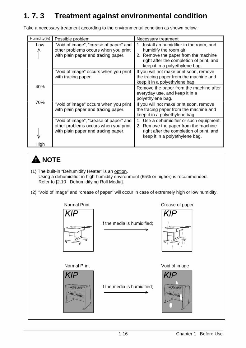
1. 7. 3 Treatment against environmental condition Take a necessary treatment according to the environmental condition as shown below.
Humidity(%) Possible problem Necessary treatment Low
40%
70%
High
“Void of image”, “crease of paper” and other problems occurs when you print with plain paper and tracing paper.
1. Install an humidifier in the room, and humidify the room air. 2. Remove the paper from the machine right after the completion of print, and keep it in a polyethylene bag.
“Void of image” occurs when you print with tracing paper.
If you will not make print soon, remove the tracing paper from the machine and keep it in a polyethylene bag.
Remove the paper from the machine after everyday use, and keep it in a polyethylene bag.
“Void of image” occurs when you print with plain paper and tracing paper.
If you will not make print soon, remove the tracing paper from the machine and keep it in a polyethylene bag.
“Void of image”, “crease of paper” and other problems occurs when you print with plain paper and tracing paper.
1. Use a dehumidifier or such equipment. 2. Remove the paper from the machine right after the completion of print, and keep it in a polyethylene bag.
NOTE (1) The built-in “Dehumidify Heater” is an option. Using a dehumidifier in high humidity environment (65% or higher) is recommended. Refer to [2.10 Dehumidifying Roll Media]. (2) “Void of image” and “crease of paper” will occur in case of extremely high or low humidity.
Normal Print
Normal Print
If the media is humidified;
If the media is humidified;
Crease of paper
Void of image
Chapter 2 Basic Operation 2-1
Chapter 2
Basic Operation Page 2. 1 Turning on KIP 770 2- 2 2. 2 Turning off KIP 770 2- 4 2. 3 Replacing Roll Media 2- 5 2. 4 Initial Cut 2- 9 2. 5 Toner Supply 2-10 2. 6 Cut Sheet Media 2-14 2. 7 Copying 2-15 2. 8 Stop of Scan or Copy 2-16 2. 9 Canceling Sleep Mode 2-17 2. 10 Dehumidifying Roll Media 2-18
Chapter 2 Basic Operation 2-2
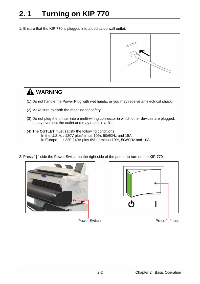
2. 1 Turning on KIP 770 1. Ensure that the KIP 770 is plugged into a dedicated wall outlet. 2. Press “ | ” side the Power Switch on the right side of the printer to turn on the KIP 770.
Power Switch Press “ | “ side.
WARNING (1) Do not handle the Power Plug with wet hands, or you may receive an electrical shock. (2) Make sure to earth the machine for safety. (3) Do not plug the printer into a multi-wiring connector in which other devices are plugged.
It may overheat the outlet and may result in a fire. (4) The OUTLET must satisfy the following conditions. In the U.S.A. : 120V plus/minus 10%, 50/60Hz and 15A In Europe : 220-240V plus 6% or minus 10%, 50/60Hz and 10A
Chapter 2 Basic Operation 2-3
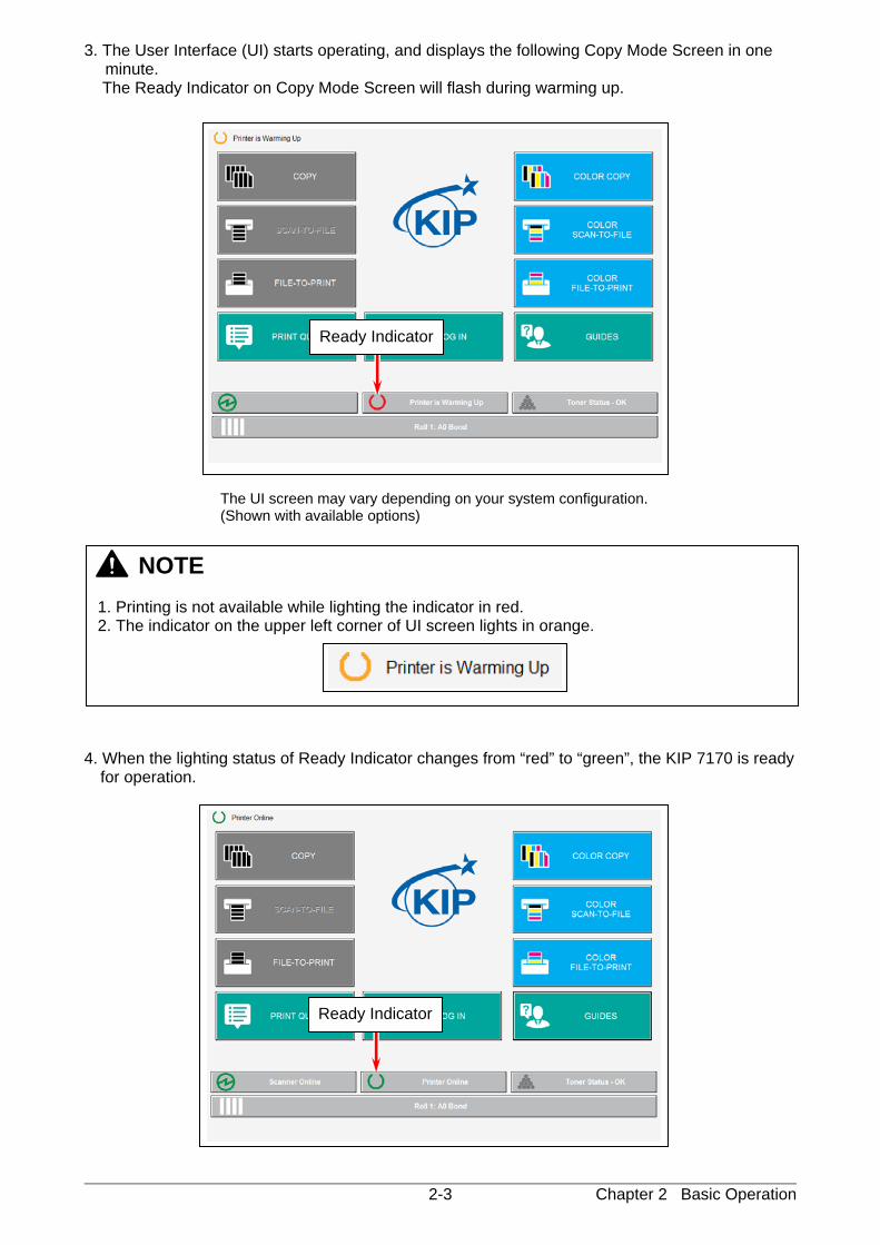
3. The User Interface (UI) starts operating, and displays the following Copy Mode Screen in one minute.
The Ready Indicator on Copy Mode Screen will flash during warming up.
The UI screen may vary depending on your system configuration. (Shown with available options)
4. When the lighting status of Ready Indicator changes from “red” to “green”, the KIP 7170 is ready
for operation.
NOTE 1. Printing is not available while lighting the indicator in red. 2. The indicator on the upper left corner of UI screen lights in orange.
Ready Indicator
Ready Indicator
Chapter 2 Basic Operation 2-4
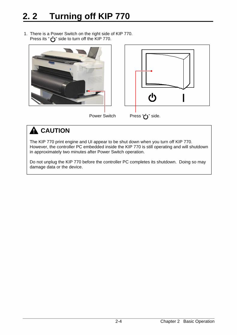
2. 2 Turning off KIP 770 1. There is a Power Switch on the right side of KIP 770. Press its “ ” side to turn off the KIP 770.
CAUTION The KIP 770 print engine and UI appear to be shut down when you turn off KIP 770. However, the controller PC embedded inside the KIP 770 is still operating and will shutdown in approximately two minutes after Power Switch operation. Do not unplug the KIP 770 before the controller PC completes its shutdown. Doing so may damage data or the device.
Power Switch Press “ ” side.
Chapter 2 Basic Operation 2-5
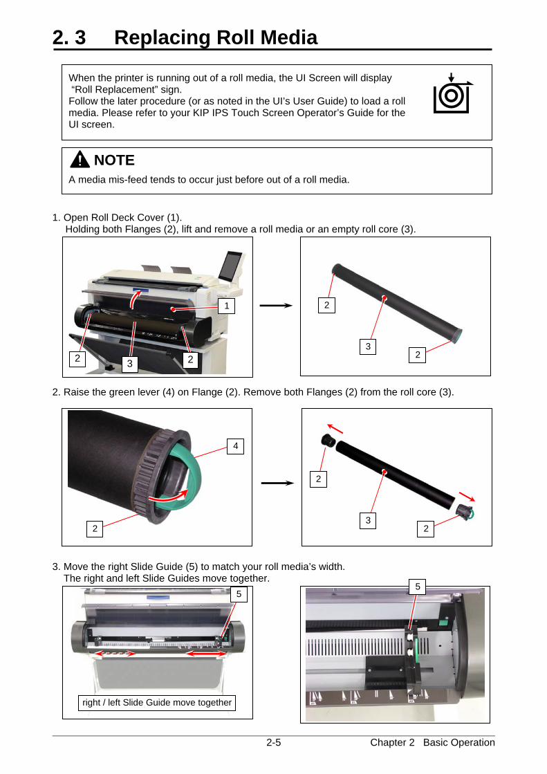
2. 3 Replacing Roll Media 1. Open Roll Deck Cover (1).
Holding both Flanges (2), lift and remove a roll media or an empty roll core (3). 2. Raise the green lever (4) on Flange (2). Remove both Flanges (2) from the roll core (3). 3. Move the right Slide Guide (5) to match your roll media’s width. The right and left Slide Guides move together.
NOTE
A media mis-feed tends to occur just before out of a roll media.
3
4
2
5 5
right / left Slide Guide move together
2
2
3
2
2
2 2 3
1
When the printer is running out of a roll media, the UI Screen will display “Roll Replacement” sign. Follow the later procedure (or as noted in the UI’s User Guide) to load a roll media. Please refer to your KIP IPS Touch Screen Operator’s Guide for the UI screen.
Chapter 2 Basic Operation 2-6
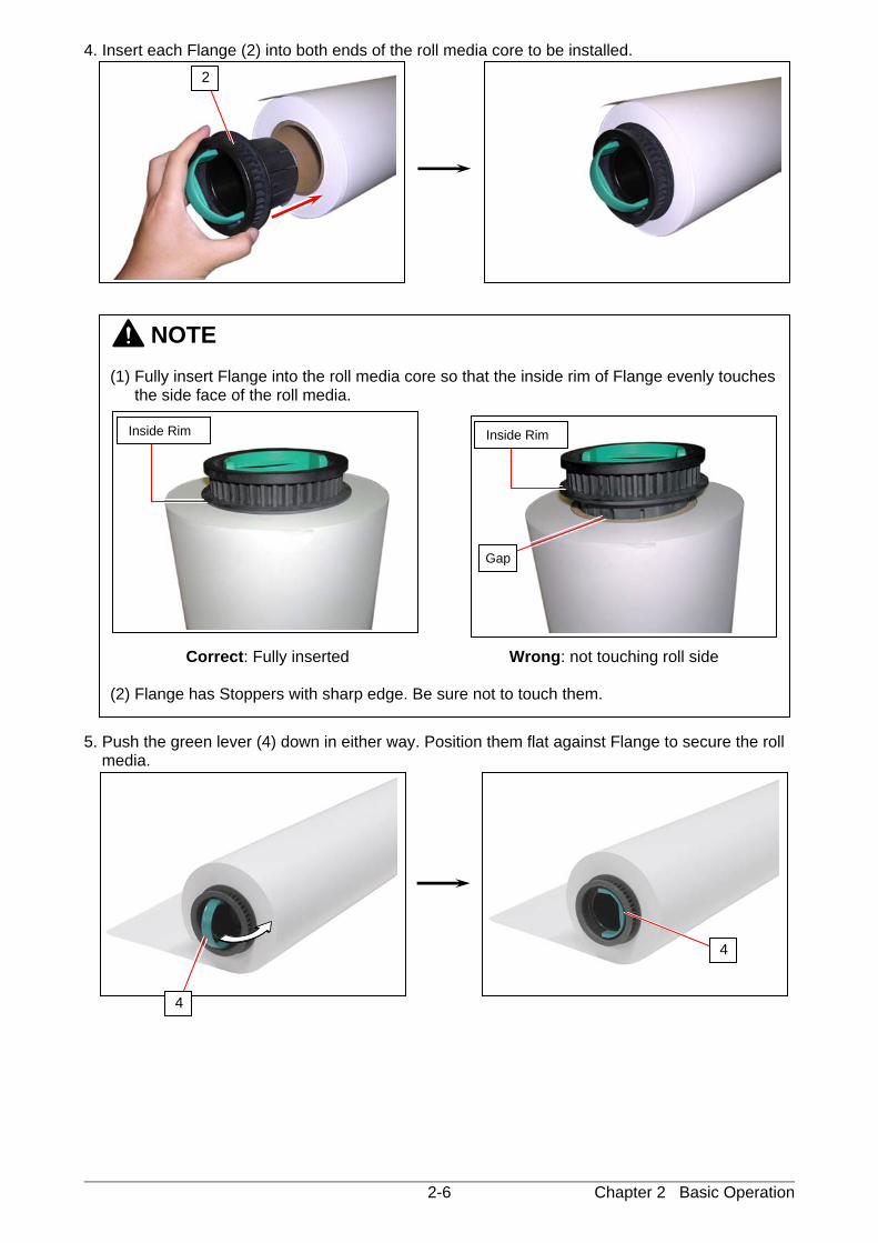
4. Insert each Flange (2) into both ends of the roll media core to be installed. 5. Push the green lever (4) down in either way. Position them flat against Flange to secure the roll
media.
NOTE (1) Fully insert Flange into the roll media core so that the inside rim of Flange evenly touches
the side face of the roll media. Correct: Fully inserted Wrong: not touching roll side (2) Flange has Stoppers with sharp edge. Be sure not to touch them.
Inside Rim Inside Rim
Gap
2
4
4
Chapter 2 Basic Operation 2-7
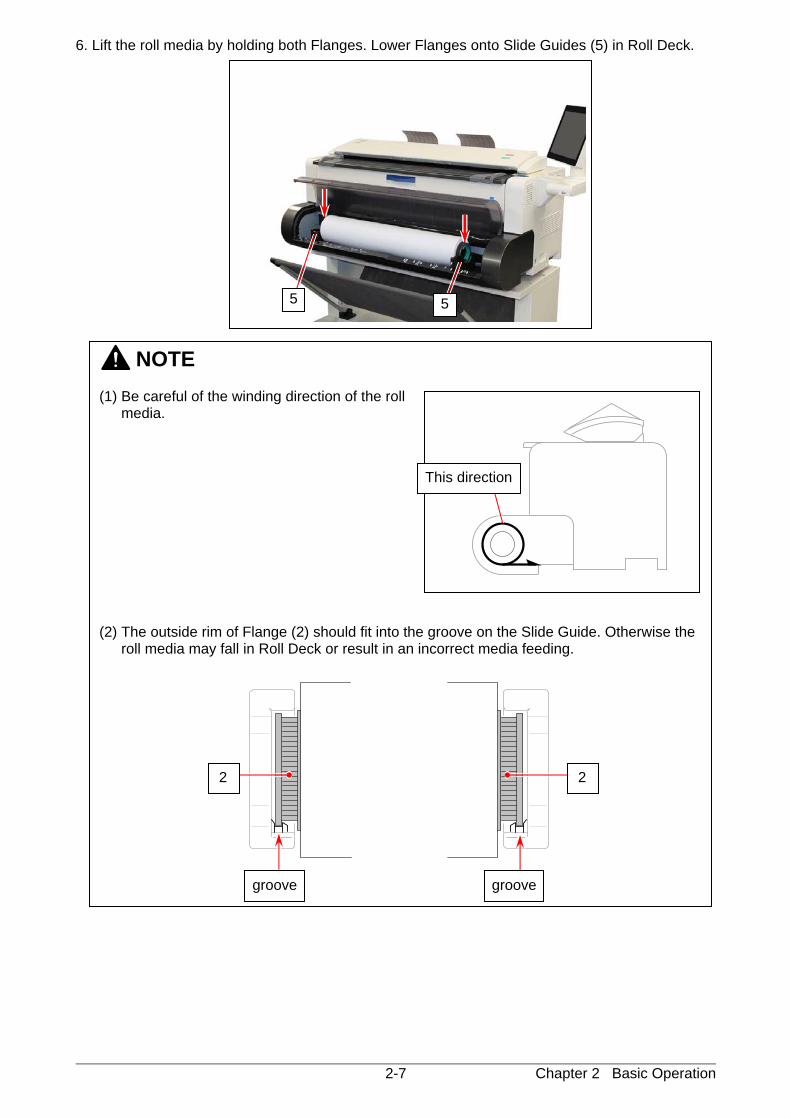
6. Lift the roll media by holding both Flanges. Lower Flanges onto Slide Guides (5) in Roll Deck.
NOTE (1) Be careful of the winding direction of the roll
media. (2) The outside rim of Flange (2) should fit into the groove on the Slide Guide. Otherwise the
roll media may fall in Roll Deck or result in an incorrect media feeding.
This direction
groove groove
2 2
5 5
Chapter 2 Basic Operation 2-8
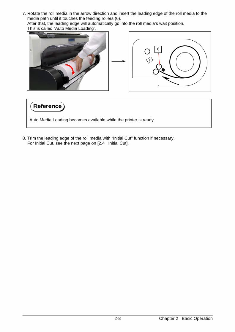
7. Rotate the roll media in the arrow direction and insert the leading edge of the roll media to the media path until it touches the feeding rollers (6).
After that, the leading edge will automatically go into the roll media’s wait position. This is called “Auto Media Loading”. 8. Trim the leading edge of the roll media with “Initial Cut” function if necessary. For Initial Cut, see the next page on [2.4 Initial Cut].
Reference
Auto Media Loading becomes available while the printer is ready.
6
Chapter 2 Basic Operation 2-9
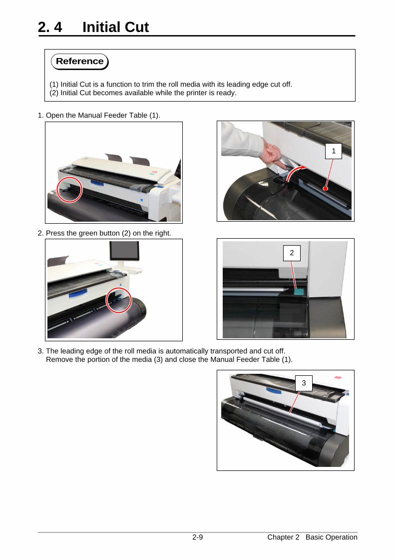
2. 4 Initial Cut 1. Open the Manual Feeder Table (1). 2. Press the green button (2) on the right. 3. The leading edge of the roll media is automatically transported and cut off. Remove the portion of the media (3) and close the Manual Feeder Table (1).
1
2
3
Reference
(1) Initial Cut is a function to trim the roll media with its leading edge cut off. (2) Initial Cut becomes available while the printer is ready.
Chapter 2 Basic Operation 2-10
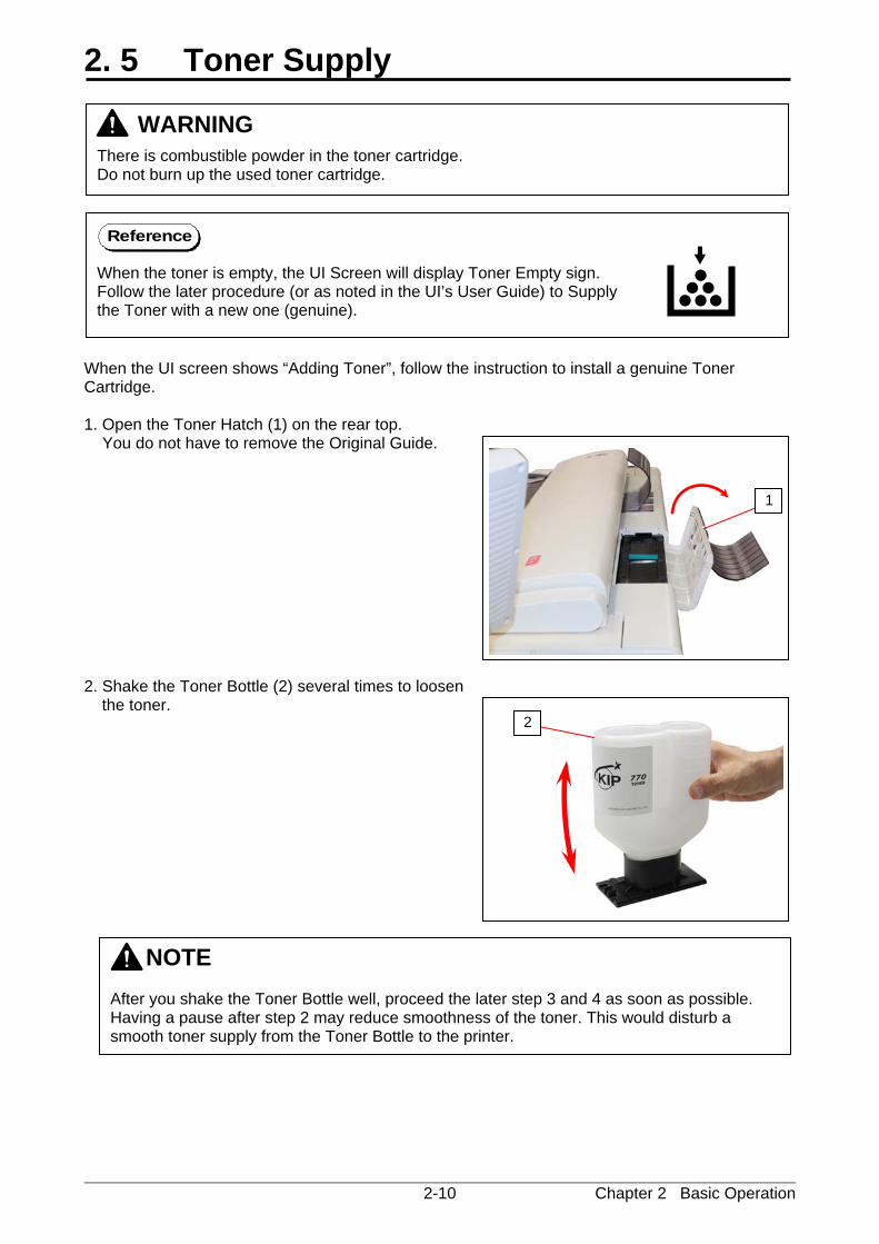
2. 5 Toner Supply When the UI screen shows “Adding Toner”, follow the instruction to install a genuine Toner Cartridge. 1. Open the Toner Hatch (1) on the rear top. You do not have to remove the Original Guide. 2. Shake the Toner Bottle (2) several times to loosen
the toner.
NOTE After you shake the Toner Bottle well, proceed the later step 3 and 4 as soon as possible. Having a pause after step 2 may reduce smoothness of the toner. This would disturb a smooth toner supply from the Toner Bottle to the printer.
2
WARNING
There is combustible powder in the toner cartridge. Do not burn up the used toner cartridge.
1
When the toner is empty, the UI Screen will display Toner Empty sign. Follow the later procedure (or as noted in the UI’s User Guide) to Supply the Toner with a new one (genuine).
Reference
Chapter 2 Basic Operation 2-11
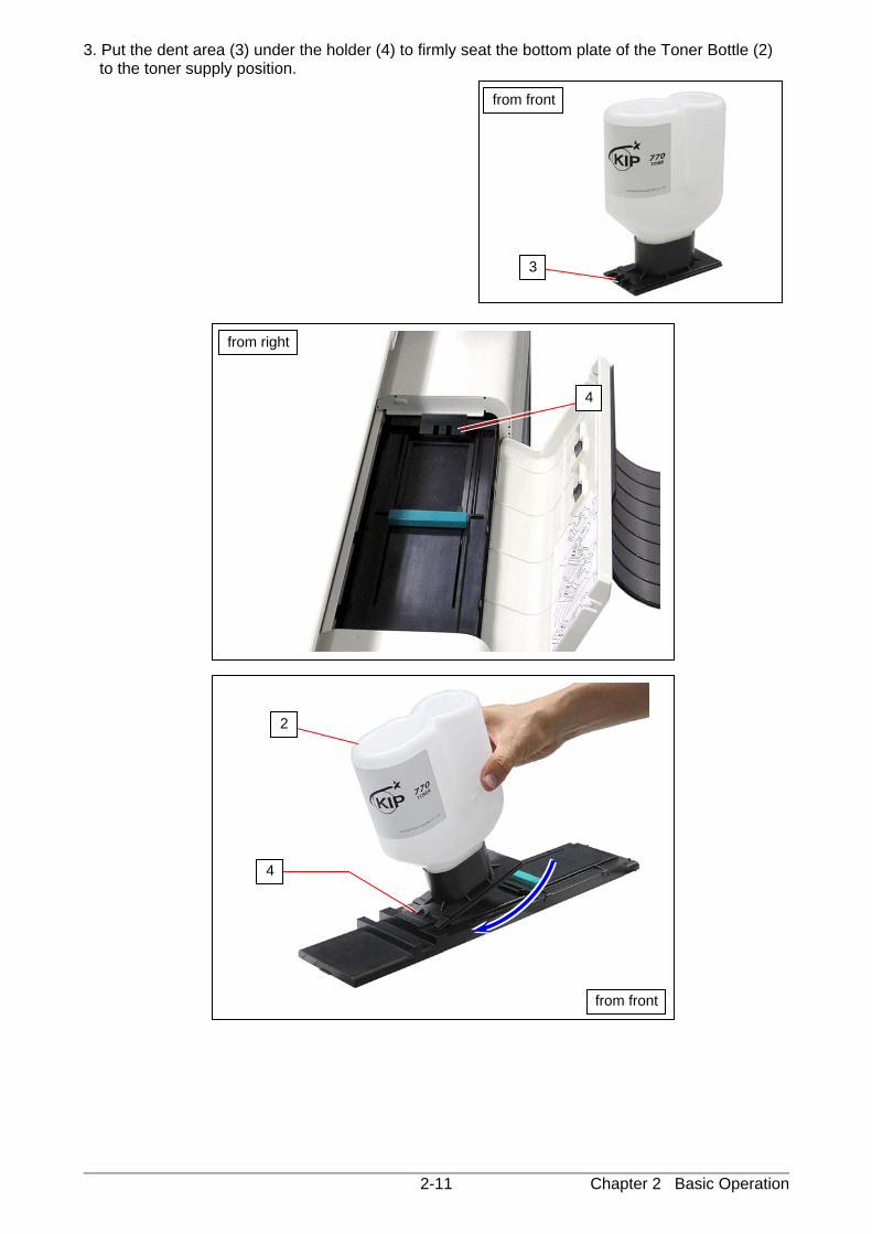
3. Put the dent area (3) under the holder (4) to firmly seat the bottom plate of the Toner Bottle (2) to the toner supply position.
4
from right
from front
3
2
from front
4
Chapter 2 Basic Operation 2-12
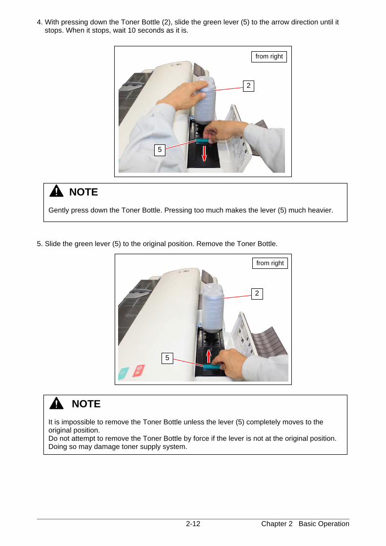
4. With pressing down the Toner Bottle (2), slide the green lever (5) to the arrow direction until it stops. When it stops, wait 10 seconds as it is.
5. Slide the green lever (5) to the original position. Remove the Toner Bottle.
NOTE It is impossible to remove the Toner Bottle unless the lever (5) completely moves to the original position. Do not attempt to remove the Toner Bottle by force if the lever is not at the original position. Doing so may damage toner supply system.
NOTE Gently press down the Toner Bottle. Pressing too much makes the lever (5) much heavier.
5
2
from right
5
2
from right
Chapter 2 Basic Operation 2-13
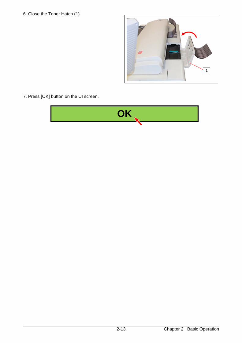
6. Close the Toner Hatch (1). 7. Press [OK] button on the UI screen.
1
OK
Chapter 2 Basic Operation 2-14
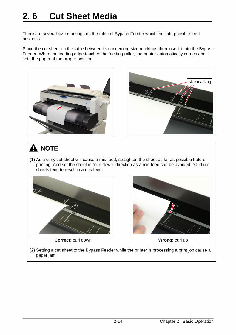
2. 6 Cut Sheet Media There are several size markings on the table of Bypass Feeder which indicate possible feed positions. Place the cut sheet on the table between its concerning size markings then insert it into the Bypass Feeder. When the leading edge touches the feeding roller, the printer automatically carries and sets the paper at the proper position.
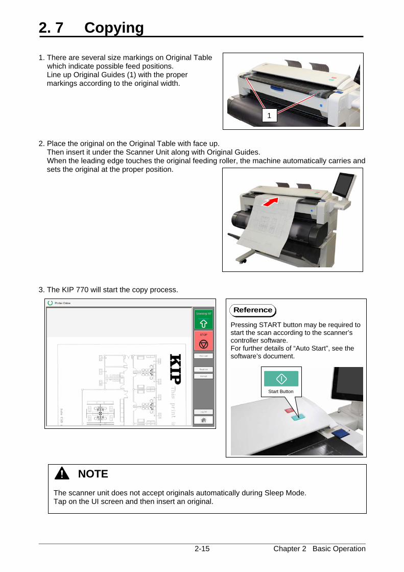
NOTE (1) As a curly cut sheet will cause a mis-feed, straighten the sheet as far as possible before
printing. And set the sheet in “curl down” direction as a mis-feed can be avoided. “Curl up” sheets tend to result in a mis-feed.
Correct: curl down Wrong: curl up (2) Setting a cut sheet to the Bypass Feeder while the printer is processing a print job cause a
paper jam.
size marking
Chapter 2 Basic Operation 2-15
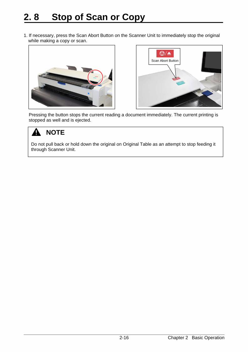
2. 7 Copying 1. There are several size markings on Original Table
which indicate possible feed positions. Line up Original Guides (1) with the proper markings according to the original width.
2. Place the original on the Original Table with face up. Then insert it under the Scanner Unit along with Original Guides. When the leading edge touches the original feeding roller, the machine automatically carries and
sets the original at the proper position. 3. The KIP 770 will start the copy process. NOTE
The scanner unit does not accept originals automatically during Sleep Mode. Tap on the UI screen and then insert an original.
1
Pressing START button may be required to start the scan according to the scanner’s controller software. For further details of “Auto Start”, see the software’s document.
Start Button
Reference
Chapter 2 Basic Operation 2-16
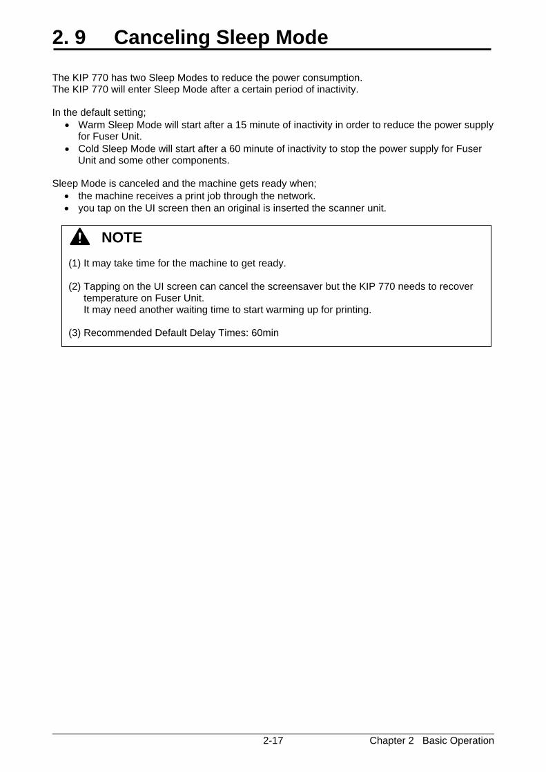
2. 8 Stop of Scan or Copy 1. If necessary, press the Scan Abort Button on the Scanner Unit to immediately stop the original
while making a copy or scan.
Pressing the button stops the current reading a document immediately. The current printing is stopped as well and is ejected.
NOTE Do not pull back or hold down the original on Original Table as an attempt to stop feeding it through Scanner Unit.
Scan Abort Button
Chapter 2 Basic Operation 2-17
2. 9 Canceling Sleep Mode The KIP 770 has two Sleep Modes to reduce the power consumption. The KIP 770 will enter Sleep Mode after a certain period of inactivity. In the default setting;
• Warm Sleep Mode will start after a 15 minute of inactivity in order to reduce the power supply for Fuser Unit.
• Cold Sleep Mode will start after a 60 minute of inactivity to stop the power supply for Fuser Unit and some other components.
Sleep Mode is canceled and the machine gets ready when;
• the machine receives a print job through the network. • you tap on the UI screen then an original is inserted the scanner unit.
NOTE (1) It may take time for the machine to get ready. (2) Tapping on the UI screen can cancel the screensaver but the KIP 770 needs to recover
temperature on Fuser Unit. It may need another waiting time to start warming up for printing.
(3) Recommended Default Delay Times: 60min
Chapter 2 Basic Operation 2-18
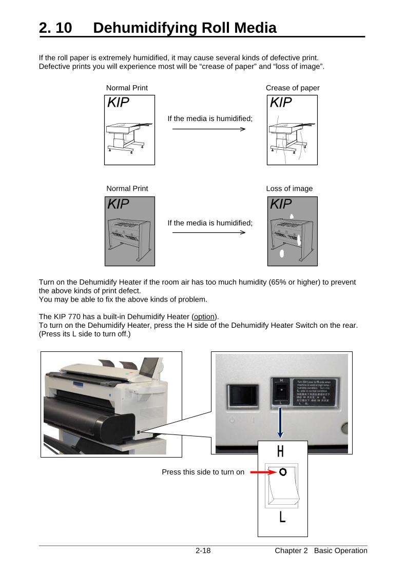
2. 10 Dehumidifying Roll Media If the roll paper is extremely humidified, it may cause several kinds of defective print. Defective prints you will experience most will be “crease of paper” and “loss of image”. Turn on the Dehumidify Heater if the room air has too much humidity (65% or higher) to prevent the above kinds of print defect. You may be able to fix the above kinds of problem. The KIP 770 has a built-in Dehumidify Heater (option). To turn on the Dehumidify Heater, press the H side of the Dehumidify Heater Switch on the rear. (Press its L side to turn off.)
Press this side to turn on
Normal Print
Normal Print
If the media is humidified;
If the media is humidified;
Crease of paper
Loss of image
H
L
Chapter 3 Error Correction 3-1
Chapter 3
Error Correction Page 3. 1 Mis-feed Error 3- 2 3. 1. 1 J-0103 Roll Deck section 3- 3 3. 1. 2 J-0203 Manual Feeder section 3- 5 3. 1. 3 J-0104 / 0204 Media Feed section 1 3- 6 3. 1. 4 J-0105 / 0205 Media Feed section 2 3- 8 3. 1. 5 J-0106 / 0206 Fuser section 3-10 3. 1. 6 J-1200 / 1300 / 1400 Door Open while printing 3-13 3. 1. 7 Original Jam 3-16 3. 2 Other Operator Call Error 3-17 3. 2. 1 Roll Replacement 3-17 3. 2. 2 Toner Empty 3-17 3. 2. 3 Scanner Open 3-17 3. 3 Service Call Error 3-18
Chapter 3 Error Correction 3-2
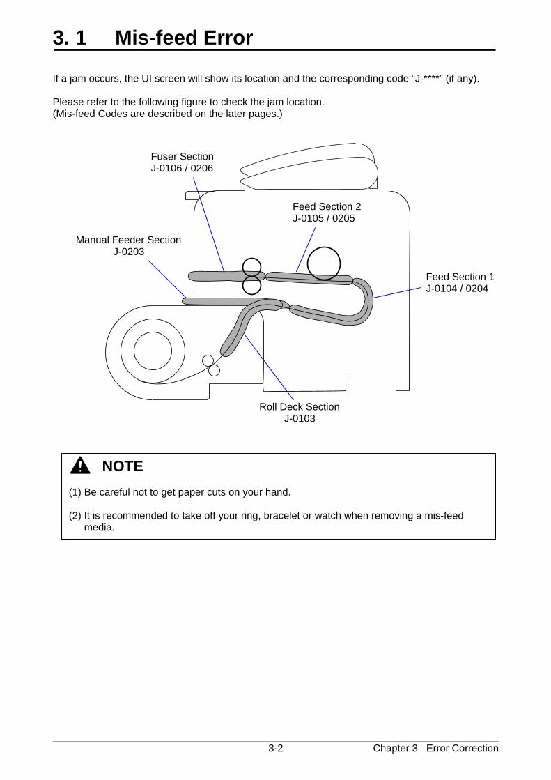
3. 1 Mis-feed Error If a jam occurs, the UI screen will show its location and the corresponding code “J-****” (if any). Please refer to the following figure to check the jam location. (Mis-feed Codes are described on the later pages.)
NOTE (1) Be careful not to get paper cuts on your hand. (2) It is recommended to take off your ring, bracelet or watch when removing a mis-feed
media.
Fuser Section J-0106 / 0206
Feed Section 1 J-0104 / 0204
Feed Section 2 J-0105 / 0205
Manual Feeder Section J-0203
Roll Deck SectionJ-0103
Chapter 3 Error Correction 3-3
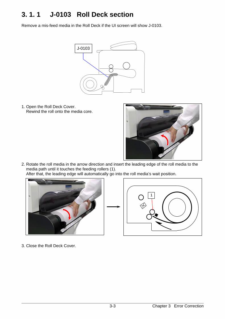
3. 1. 1 J-0103 Roll Deck section Remove a mis-feed media in the Roll Deck if the UI screen will show J-0103.
1. Open the Roll Deck Cover. Rewind the roll onto the media core. 2. Rotate the roll media in the arrow direction and insert the leading edge of the roll media to the
media path until it touches the feeding rollers (1). After that, the leading edge will automatically go into the roll media’s wait position. 3. Close the Roll Deck Cover.
J-0103
1
Chapter 3 Error Correction 3-4
Reference
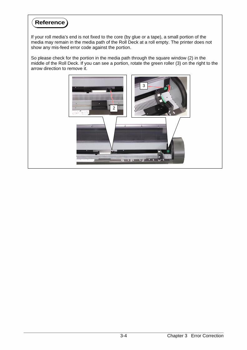
If your roll media’s end is not fixed to the core (by glue or a tape), a small portion of the media may remain in the media path of the Roll Deck at a roll empty. The printer does not show any mis-feed error code against the portion. So please check for the portion in the media path through the square window (2) in the middle of the Roll Deck. If you can see a portion, rotate the green roller (3) on the right to the arrow direction to remove it.
2
3
Chapter 3 Error Correction 3-5
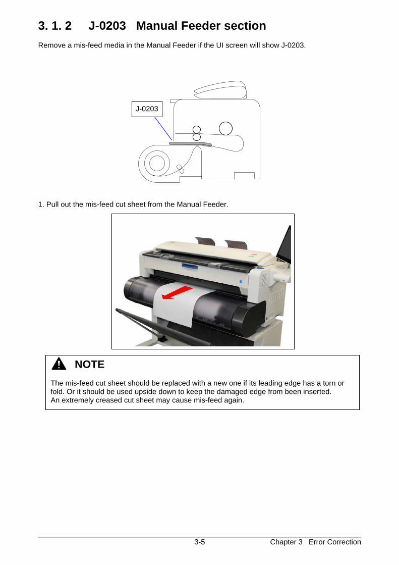
3. 1. 2 J-0203 Manual Feeder section Remove a mis-feed media in the Manual Feeder if the UI screen will show J-0203.
1. Pull out the mis-feed cut sheet from the Manual Feeder.
J-0203
NOTE The mis-feed cut sheet should be replaced with a new one if its leading edge has a torn or fold. Or it should be used upside down to keep the damaged edge from been inserted. An extremely creased cut sheet may cause mis-feed again.
Chapter 3 Error Correction 3-6
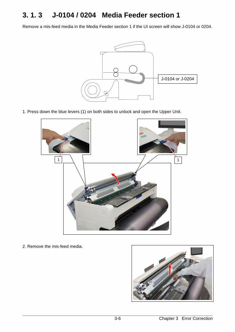
3. 1. 3 J-0104 / 0204 Media Feeder section 1 Remove a mis-feed media in the Media Feeder section 1 if the UI screen will show J-0104 or 0204.
1. Press down the blue levers (1) on both sides to unlock and open the Upper Unit. 2. Remove the mis-feed media.
J-0104 or J-0204
1 1

Chapter 3 Error Correction 3-7
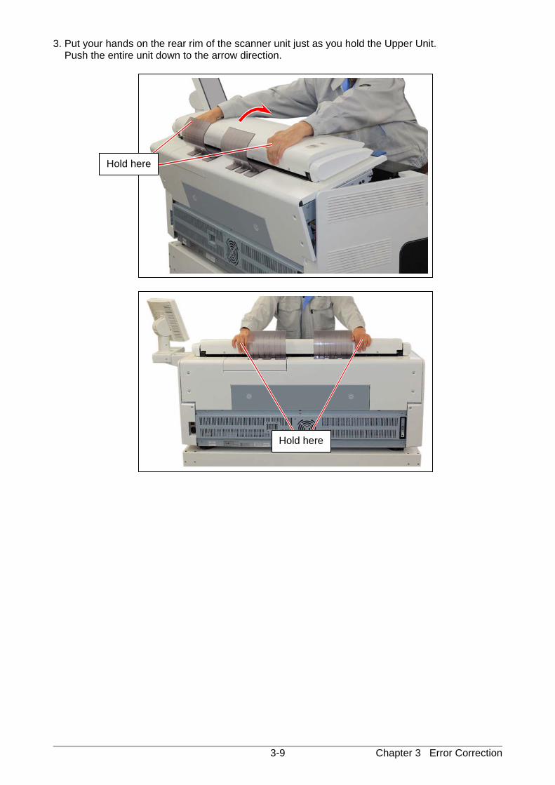
3. Put your hands on the rear rim of the scanner unit just as you hold the Upper Unit. Push the entire unit down to the arrow direction.
Hold here
Hold here
Chapter 3 Error Correction 3-8
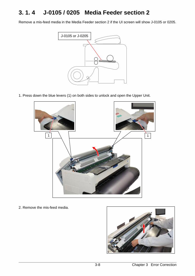
3. 1. 4 J-0105 / 0205 Media Feeder section 2 Remove a mis-feed media in the Media Feeder section 2 if the UI screen will show J-0105 or 0205.
1. Press down the blue levers (1) on both sides to unlock and open the Upper Unit. 2. Remove the mis-feed media.
1 1
J-0105 or J-0205
Chapter 3 Error Correction 3-9
3. Put your hands on the rear rim of the scanner unit just as you hold the Upper Unit. Push the entire unit down to the arrow direction.
Hold here
Hold here
Chapter 3 Error Correction 3-10
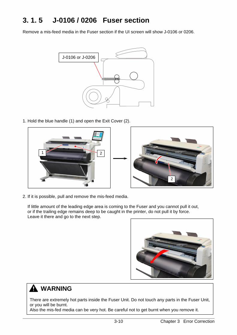
3. 1. 5 J-0106 / 0206 Fuser section Remove a mis-feed media in the Fuser section if the UI screen will show J-0106 or 0206.
1. Hold the blue handle (1) and open the Exit Cover (2).
2. If it is possible, pull and remove the mis-feed media.
If little amount of the leading edge area is coming to the Fuser and you cannot pull it out, or if the trailing edge remains deep to be caught in the printer, do not pull it by force. Leave it there and go to the next step.
J-0106 or J-0206
WARNING There are extremely hot parts inside the Fuser Unit. Do not touch any parts in the Fuser Unit, or you will be burnt. Also the mis-fed media can be very hot. Be careful not to get burnt when you remove it.
1 2
2
Chapter 3 Error Correction 3-11
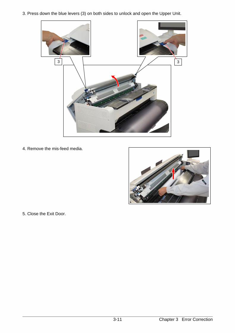
3. Press down the blue levers (3) on both sides to unlock and open the Upper Unit. 4. Remove the mis-feed media. 5. Close the Exit Door.
3 3
Chapter 3 Error Correction 3-12
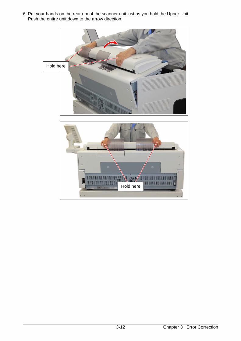
6. Put your hands on the rear rim of the scanner unit just as you hold the Upper Unit. Push the entire unit down to the arrow direction.
Hold here
Hold here
Chapter 3 Error Correction 3-13
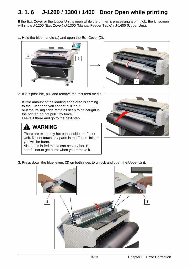
3. 1. 6 J-1200 / 1300 / 1400 Door Open while printing If the Exit Cover or the Upper Unit is open while the printer is processing a print job, the UI screen will show J-1200 (Exit Cover) /J-1300 (Manual Feeder Table) / J-1400 (Upper Unit). 1. Hold the blue handle (1) and open the Exit Cover (2). 2. If it is possible, pull and remove the mis-feed media.
If little amount of the leading edge area is coming to the Fuser and you cannot pull it out, or if the trailing edge remains deep to be caught in the printer, do not pull it by force. Leave it there and go to the next step.
3. Press down the blue levers (3) on both sides to unlock and open the Upper Unit.
3 3
WARNING
There are extremely hot parts inside the Fuser Unit. Do not touch any parts in the Fuser Unit, or you will be burnt. Also the mis-fed media can be very hot. Be careful not to get burnt when you remove it.
1 2
2
Chapter 3 Error Correction 3-14
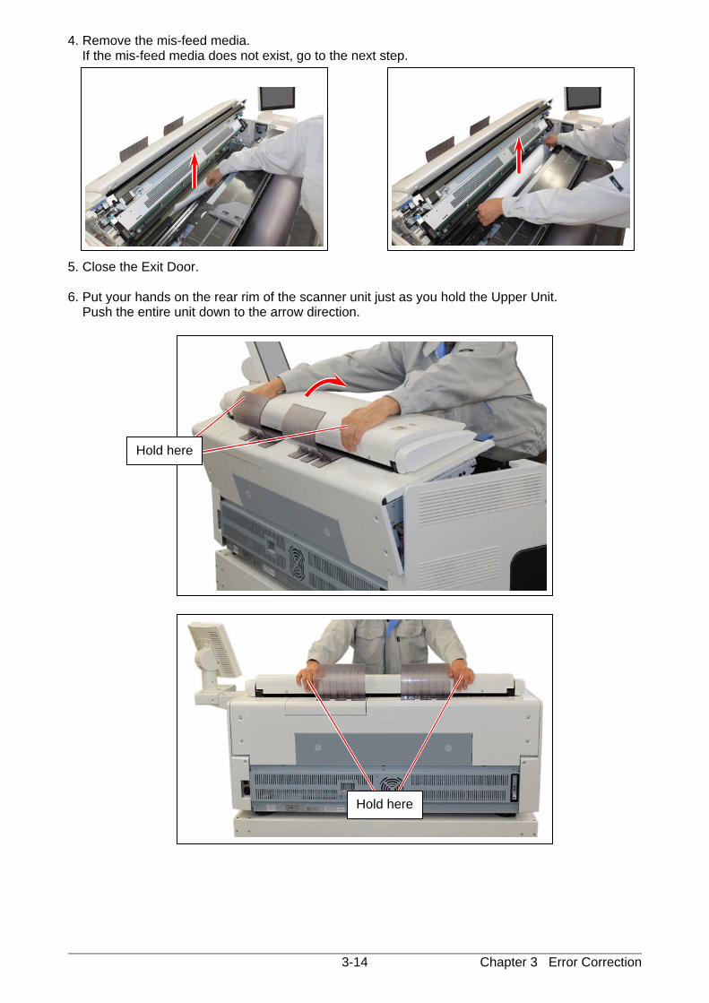
4. Remove the mis-feed media. If the mis-feed media does not exist, go to the next step.
5. Close the Exit Door. 6. Put your hands on the rear rim of the scanner unit just as you hold the Upper Unit. Push the entire unit down to the arrow direction.
Hold here
Hold here
Chapter 3 Error Correction 3-15
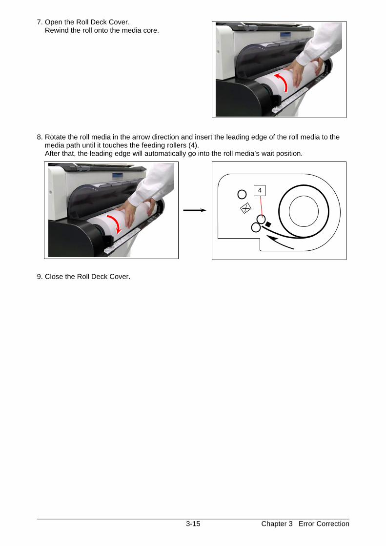
7. Open the Roll Deck Cover. Rewind the roll onto the media core. 8. Rotate the roll media in the arrow direction and insert the leading edge of the roll media to the
media path until it touches the feeding rollers (4). After that, the leading edge will automatically go into the roll media’s wait position. 9. Close the Roll Deck Cover.
4
Chapter 3 Error Correction 3-16
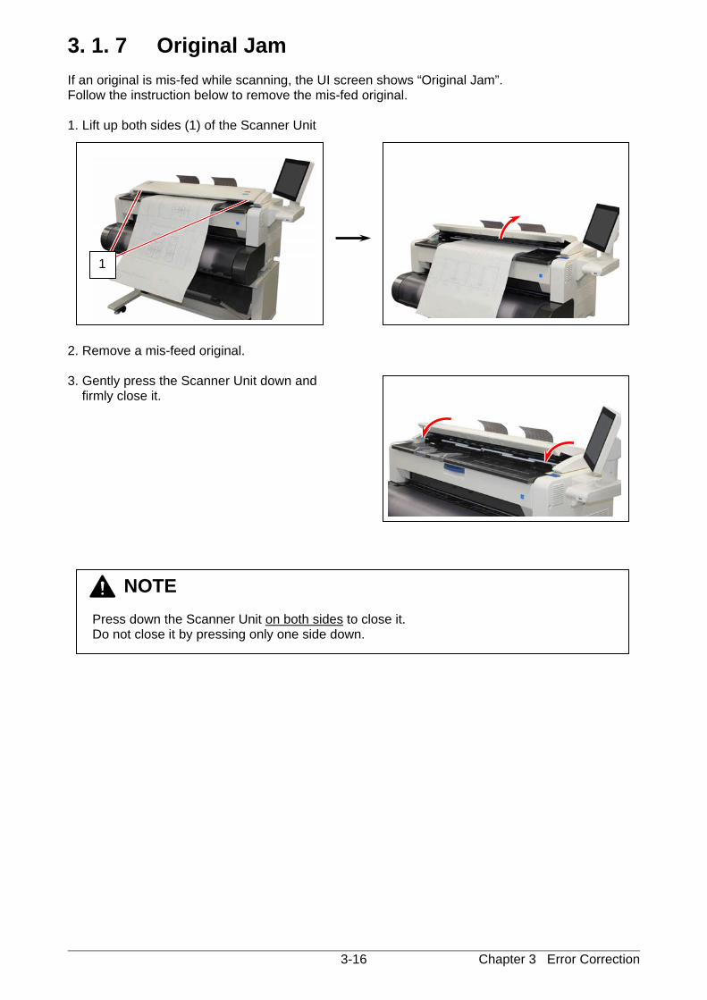
3. 1. 7 Original Jam If an original is mis-fed while scanning, the UI screen shows “Original Jam”. Follow the instruction below to remove the mis-fed original. 1. Lift up both sides (1) of the Scanner Unit 2. Remove a mis-feed original. 3. Gently press the Scanner Unit down and
firmly close it.
NOTE Press down the Scanner Unit on both sides to close it. Do not close it by pressing only one side down.
1
Chapter 3 Error Correction 3-17
3. 2 Other Operator Call Error
3. 2. 1 Roll Replacement When the printer is running out of a loaded roll media, the UI Screen will display “Roll Replacement” sign. If there is no suitable roll media required for the current print job, the UI Screen will display “Roll Replacement” sign as well. Please load the required roll media to any Roll Deck. For the roll replacement procedure, see [2.3 Replacing Roll Media].
3. 2. 2 Toner Empty When the printer is running out of toner, the UI Screen will display “Toner Empty” sign. For the toner supply procedure, see [2.5 Toner Supply].
3. 2. 3 Scanner Unit Open The UI screen shows “Scanner Unit Open” if the Scanner Unit is open. (not closed properly) For closing the Scanner Unit, see [3.1.7 Original Jam].
Chapter 3 Error Correction 3-18
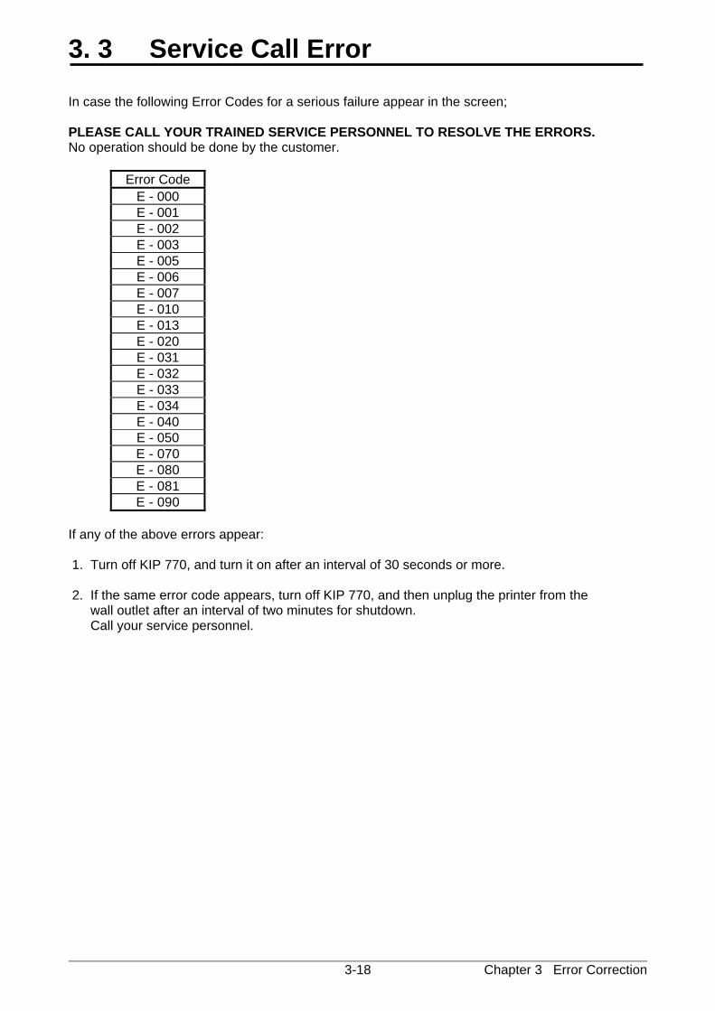
3. 3 Service Call Error In case the following Error Codes for a serious failure appear in the screen; PLEASE CALL YOUR TRAINED SERVICE PERSONNEL TO RESOLVE THE ERRORS. No operation should be done by the customer.
Error Code E - 000 E - 001 E - 002 E - 003 E - 005 E - 006 E - 007 E - 010 E - 013 E - 020 E - 031 E - 032 E - 033 E - 034 E - 040 E - 050 E - 070 E - 080 E - 081 E - 090
If any of the above errors appear: 1. Turn off KIP 770, and turn it on after an interval of 30 seconds or more. 2. If the same error code appears, turn off KIP 770, and then unplug the printer from the wall outlet after an interval of two minutes for shutdown. Call your service personnel.

Chapter 4 Maintenance 4-1
Chapter 4
Maintenance Page 4. 1 Scanner Unit 4- 2
4. 1. 1 Scan Glass, Feed Roller, Guide Plate 4- 2 4. 1. 2 Sensor 4- 5
4. 2 Touch Screen 4- 7
Chapter 4 Maintenance 4-2
4. 1 Scanner Unit
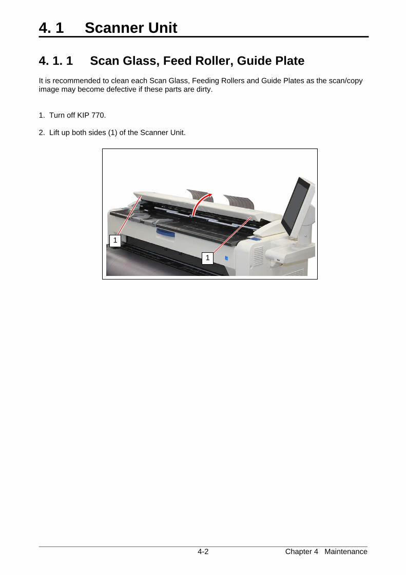
4. 1. 1 Scan Glass, Feed Roller, Guide Plate It is recommended to clean each Scan Glass, Feeding Rollers and Guide Plates as the scan/copy image may become defective if these parts are dirty. 1. Turn off KIP 770. 2. Lift up both sides (1) of the Scanner Unit.
1
1
Chapter 4 Maintenance 4-3
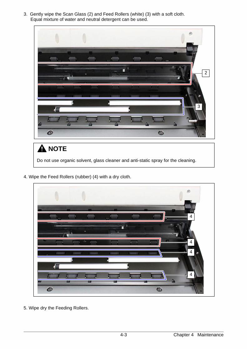
3. Gently wipe the Scan Glass (2) and Feed Rollers (white) (3) with a soft cloth. Equal mixture of water and neutral detergent can be used.
4. Wipe the Feed Rollers (rubber) (4) with a dry cloth. 5. Wipe dry the Feeding Rollers.
NOTE Do not use organic solvent, glass cleaner and anti-static spray for the cleaning.
2
3
4
4
4
4
Chapter 4 Maintenance 4-4
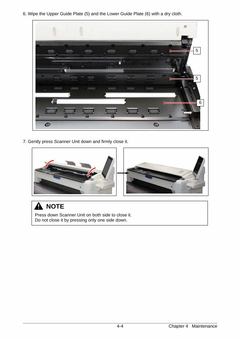
6. Wipe the Upper Guide Plate (5) and the Lower Guide Plate (6) with a dry cloth. 7. Gently press Scanner Unit down and firmly close it.
NOTE
Press down Scanner Unit on both side to close it. Do not close it by pressing only one side down.
5
6
5
Chapter 4 Maintenance 4-5
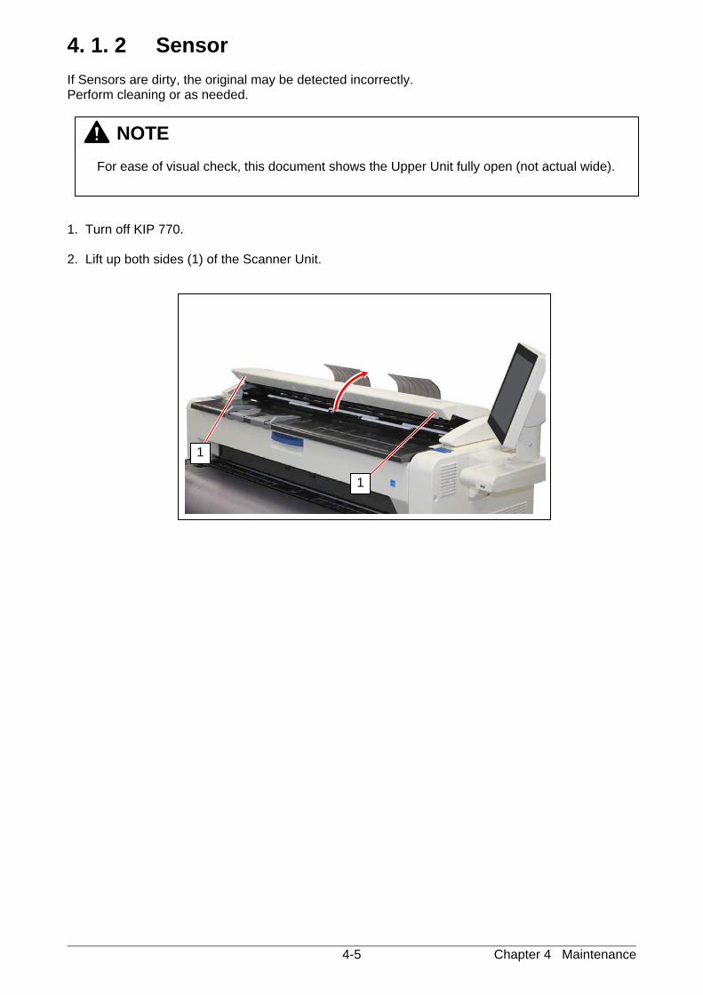
4. 1. 2 Sensor If Sensors are dirty, the original may be detected incorrectly. Perform cleaning or as needed. 1. Turn off KIP 770. 2. Lift up both sides (1) of the Scanner Unit.
NOTE
For ease of visual check, this document shows the Upper Unit fully open (not actual wide).
1
1
Chapter 4 Maintenance 4-6
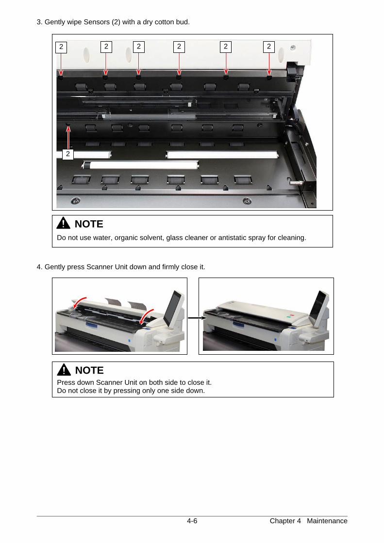
3. Gently wipe Sensors (2) with a dry cotton bud. 4. Gently press Scanner Unit down and firmly close it.
NOTE
Do not use water, organic solvent, glass cleaner or antistatic spray for cleaning.
NOTE
Press down Scanner Unit on both side to close it. Do not close it by pressing only one side down.
2 2 2 2 2 2
2
Chapter 4 Maintenance 4-7
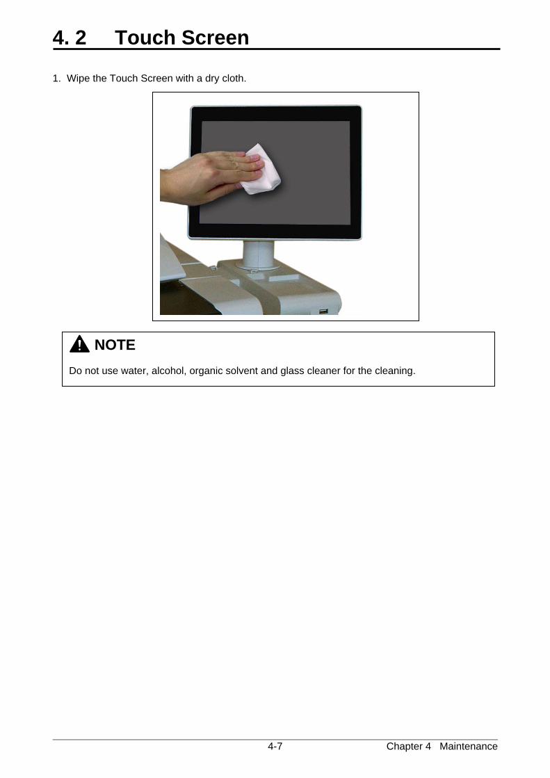
4. 2 Touch Screen 1. Wipe the Touch Screen with a dry cloth.
NOTE Do not use water, alcohol, organic solvent and glass cleaner for the cleaning.

58
© 2014 KATSURAGAWA ELECTRIC CO., LTD. No part of this publication may be copied, reproduced or distributed in any form without express written permission from Katsuragawa Electric Co., Ltd.