Embed Size (px)
Citation preview
Knowledge-Based Engineering Approach to Support AircraftMultidisciplinary Design and Optimization
Gianfranco La Rocca∗ and Michel J. L. van Tooren†
Delft University of Technology, 2629 HS Delft, The Netherlands
DOI: 10.2514/1.39028
This paper introduces the concept of the design and engineering engine, which is a modular computational design
system to support distributed multidisciplinary design and optimization of aircraft. In particular, this paper
discusses the architecture and the functionalities of the multimodel generator module, which is a knowledge-based
engineering application developed tomodel the geometry of both conventional and novel aircraft configurations and
to automate the generation of dedicatedmodels for low- and high-fidelity analysis tools. This paper demonstrates the
capability of the knowledge-based engineering approach to record and automate complex engineering design
processes, such as the generation of models for finite element analysis. The time reduction gained by process
automation, together with the enabled use of high-fidelity analysis tools earlier in the design process, constitute
significant achievements toward a broader exploitation of the multidisciplinary design and optimization method-
ology, as well as the development of novel aircraft configurations.
I. Introduction
M ULTIDISCIPLINARY design optimization (MDO) isrecognized to be one of the most promising methodologies
in the field of aircraft design and the design of complex products ingeneral [1,2]. However, a number of technical and nontechnicalbarriers are constraining its transition from a promising to a con-solidated and routinely exploited methodology. After almost 30years of development in the field of applied optimization techniques,MDO still struggles to get the same attention of the traditionaldisciplines in the field of aerospace engineering. In the early years,the low-fidelity level of the analysis tools applicable in MDOframeworks and the low computational power were the mainlimitations [3]. In 1998, a review study carried out by the AIAAMDO technical committee [4] revealed that the exploitation ofMDOwas still hampered by the problematic use of high-fidelity tools. Amultidisciplinary design and optimization approach was still onlypossible by using low-levelfidelity analysis tools, although the use ofcomputational fluid dynamics (CFD) and finite-element-method(FEM) tools was limited to tradeoff studies and monodisciplinarydesign cases. At that time, the use of genuine MDO methods withinthe industry at large was still rather limited and mostly confinedto the detail design phase [5]. Including high-fidelity analysis tools ina MDO framework for conceptual design of complete aircraftconfigurations was not yet common practice [6,7]. The lack ofrobustness and flexibility of high-fidelity analysis tools still forceddesigners to use lengthy andmostly manual preprocessing activities,and the level of achieved automationwas not yet sufficient to supportthe highly iterative nature of the MDO approach. However, theavailability of MDO systems based on the use of accurate physics-based analysis tools was an absolute necessity to support the designof novel aircraft configurations, such as blended wing bodies [8] orPrandtlPlanes [9]. As elaborated by Bowcutt [10] and Morris [11],the high-level of integration in such designs required (and benefits
the most from) a true multidisciplinary and optimization approach.The use of simple conceptual rules from the classical handbookdesignmethods became useless due to the lack of any statistic base orexperience from past aircraft development programs.
Advances in the exploitation of the MDO require the imple-mentation of a different organizational structure in a company, asdiscussed in [12–14]. At the same time, the development of any newMDO framework must account for the possibility to supportcollaborative design. Discipline specialists from different groups,departments, and companies (often nongeographically collocated)should be able to collaboratewithin large design programs while stillmaking use of their own well-trusted design and analysis tools.
On the basis of the previous considerations, it is clear thatadvances in the field of MDO do not depend exclusively on theavailability of faster computers or more efficient optimizationalgorithms but on the overall development of computational frame-works geared toward flexibility, automation, and exploitation ofhigh-fidelity analysis systems [15]. A nonexhaustive list of needsfollows, which any computational design system aimed at sup-porting the MDO approach should be able to fulfill:
1) The system structure should be easy to adapt to different designcases (not limited to conventional aircraft configurations) and to thespecific needs of the various phases of the design process.
2) The system should support the integration into one engineeringdesign environment of different design, analysis, and optimizationtools scattered across distributed and heterogeneous computernetworks.
3) The system should be able to integrate both commercial off-the-shelf (COTS) and in-house developed design, analysis, andoptimization tools.
4) The system should integrate both low- and high-fidelity analysistools.
5) The system should guarantee the coherence and synchroniza-tion of the data/models used by the various disciplinary analysis toolsinvolved in the design and optimization process.
6) The system should support automation of all the repetitiveactivities related to the iterative nature of the MDO approach,including those related to pre- and postprocessing of data andmodelsand their transfer between the various design and analysis tools
II. Paradigm of the Design and Engineering Engine
Based on the requirements discussed in the previous section, theDesign of Aircraft and Rotorcraft group of the Delft University ofTechnology started the development of a distributed com-putational design system concept called the design and engineering
Presented as Paper 967 at the 45th AIAAAerospace SciencesMeeting andExhibit, Reno, Nevada, 8–11 January 2007; received 10 June 2008; revisionreceived 26 July 2009; accepted for publication 11August 2009. Copyright ©2009 by Delft University of Technology. Published by the American Instituteof Aeronautics and Astronautics, Inc., with permission. Copies of this papermay be made for personal or internal use, on condition that the copier pay the$10.00 per-copy fee to the Copyright Clearance Center, Inc., 222 RosewoodDrive, Danvers, MA 01923; include the code 0021-8669/09 and $10.00 incorrespondence with the CCC.
∗Assistant Professor, Aerospace Engineering, Design of Aircraft andRotorcraft Division, Kluyverweg 1.
†Full Professor, Aerospace Engineering, Design of Aircraft and RotorcraftDivision, Kluyverweg 1. Member AIAA.
JOURNAL OF AIRCRAFT
Vol. 46, No. 6, November–December 2009
1875
Dow
nloa
ded
by L
inko
ping
s U
nive
rsite
tsbi
blio
tek
on A
ugus
t 17,
201
3 | h
ttp://
arc.
aiaa
.org
| D
OI:
10.
2514
/1.3
9028
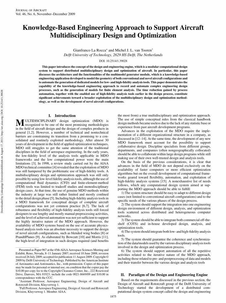
engine (DEE). The first conceptual development of the DEE wasinitiated within the framework of the European project MOB: acomputational design engine incorporating multidisciplinary designand optimization for blended wing-body configuration [11]. Sincethen, it has kept advancing through a number of national researchprojects and not exclusive collaboration with the industry. Asillustrated in Fig. 1, the DEE consists of a multidisciplinarycollection of design and analysis tools, able to interface auto-matically and exchange data and information, to support what-ifstudies and MDO. The main purpose of the DEE is to support andaccelerate the design, analysis, and optimization process of complexproducts like aircraft through the automation of noncreative andrepetitive design activities [16–18].
The following main components constitute the DEE architecture:1) The multimodel generator (MMG), which is a true knowledge-
based engineering (KBE) application developed with the twofoldintent of providing designers with a parametric modeling environ-ment (to define generative models of conventional and novel aircraftconfigurations) and feeding various analysis tools with dedicatedaircraft model abstractions (as required for the verification ofthe generated design). The MMG structure and functionality arediscussed in more detail in this paper.
2) The initiator, which is actually a set of sizing tools, is able toprovide an initial set of parameter values for the MMG. In fact, theMMGoffers the possibility to instantiate an aircraft model based on agiven set of parameter values, but it does not have any knowledge toselect/calculate those values autonomously. Various parameterinitiating tools have been (and still are being) developed (e.g., to sizea fuselage given the payload requirements or to size the trapezoidalwing planform based on mission requirements). Within the scope ofthe initiator also falls the provision of a rough estimation of themass and stiffness distribution in the aircraft structure, based on apreliminary estimation of the aerodynamic loads. Eventually, thescope of the initiator is to provide a feasible initial solution to initiatethe multidisciplinary optimization process (see the feasilizationprocess in [19]).
3) A suite of analysis tools (the discipline silos), which can be low-and/or high-fidelity analysis tools (for example, panel codes orCFD), either developed in-house or COTS. The set of analysis toolsvaries according to the design case at hand, yet it always operates ondata and models generated by the MMG.
4) The converger and evaluator box checks the various analysistools (e.g., the flow solver) to see if they have reached convergence,
evaluates if the performance/characteristics of the design meets theobjectives set by the designer, and defines the next parameter setwhen running an optimization problem.
5) The communication framework, represented in Fig. 1 by the setof connectors linking the various DEE components, takes care of thedata and information flow between the various design and analysistools and enables the overall design process sequence. The currentframework, for which the agent-based architecture is described in[20], uses web technologies to have the DEE tools communicatingwith each other, even when located on different computer networksand running on machines with different operating systems.
To participate in the DEE structure, a software component must beable to operate autonomously while exposing an adequate input/output interface. In other words, it must be able to run in batchmode, providing remote accessibility and hands-off operation. Thesecharacteristics are essential to the implementation of the DEEmodular architecture.
Thedesign teamshouldbe facilitated inadaptingand reconfiguringthe design framework according to the nature of each design case, inincorporatingnewdesignandanalysiscapabilities,andinmaintainingthe system and keeping it up to date. The modular structure of theDEE offers these opportunities, in contrast to a tightly integrateddesign system. However, modularity comes along with the over-headof buildingproper/generic interfaces and, in general, somedetri-mental effect on the data exchange speed. Despite these negativeaspects,modularityseemsaproper investment that, sofar,hasresultedin expandability, upgradability, and exploitability of the distributeddesign environment [15].
Given the central role of the MMG, the DEE systems fits in thecategory of the so-called geometry-in-the-loop design systems. Inthis sense, the DEE differs from the traditional conceptual designsystems in which geometry is generated just as final output of acomputational process based on simple statistics and/or semi-empirical equations. The DEE approach differs also from thecategory of systems based on grid perturbation [21]. Differentdedicated models are generated for each of the analysis toolsinvolved in the DEE and not just one tessellated representationtailored to the main analysis code, as discussed in [22]. This yieldsthe additional advantage that large model variations are allowedduring design space exploration, whereas grid perturbation methodsare generally limited to virtual sandpaper work.
Thepossibilityofhavingmultidisciplinary analysis toolsoperatingondedicatedandconsistentgeometrymodels, systematicallyupdated
Fig. 1 Paradigm of the DEE.
1876 LA ROCCA AND VAN TOOREN
Dow
nloa
ded
by L
inko
ping
s U
nive
rsite
tsbi
blio
tek
on A
ugus
t 17,
201
3 | h
ttp://
arc.
aiaa
.org
| D
OI:
10.
2514
/1.3
9028
at eachparametricvariation,makes theMMGtheactual technologicalenabler of thewholeDEEsystem. Indeed, advocates [10,22,23]of thegeometry-in-the-loop approach indicate the geometry generation asthe keystone to succeed and often the greatest impediment tointegrated design.
In the following sections, role, structure, and functionality of theKBE MMG are discussed in detail. In particular, the capabilities ofthe MMG to instantiate models of aircraft (or isolated componentssuch as wings and control surfaces) and generate specific sets of dataand information to support automated finite element (FE) structuralanalysis will be addressed.
III. Structure and Functionality of the MultimodelGenerator: High-Level Primitives
and Capability Modules
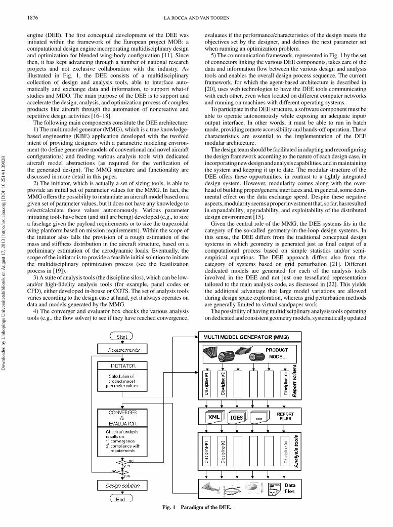
TheMMG, as shown in Fig. 1 (top right), has twomain functionalblocks, namely, the product model and the report writers. Theproductmodel represents the actual (geometry)modeling tool, whichoffers the designer the possibility to create instantiations of theaircraft concepts he/she has in mind. The MMG provides designerswith a suite of parametrical blocks, so-called high-level primitives(HLPs), which can be easily shaped and assembled to build up a largenumber of aircraft configurations and variants. Examples of theseprimitives are thewing trunk, the fuselage trunk, the engine part, andthe connection element (as shown in Fig. 2). Each primitive has beendefined in theKBE environment as a class [24,25]. The designers, viaan editable inputfile (theMMGinputfile), can assign different valuesto the given class attributes and call for multiple HLP instantiations,such that either conventional or novel aircraft configurations can begenerated and then stretched/morphed into an infinite number ofvariants. A part of the parameter/attribute set used to define thewing-trunk HLP is shown in Fig. 2 (left).
The HLP approach offers a more effectiveway to follow theway adesigner looks at an aircraft during the conceptual developmentphase than the approach offered by a conventional computer aideddesign (CAD) system. A designer sees the aircraft as an assembly ofbasic solutions to fulfill functionalities, such as generating lift andstoring payload, not as an assembly of curves, surfaces, and points.
KBE, with its peculiar capability to merge CAD and object-oriented programming [26–28], has provided all the necessaryingredients to concretize the concept of HLPs into a workingsoftware application. The programming approach is what actuallyturns the HLPs into smart entities able to contain knowledge andreuse it systematically. For example, the HLPs know how to create/modify their shape based on a set of input parameters; they knowhowto connect to each other maintaining continuity and integrity (i.e.,keeping outer surface and inner structure properly connected).
Furthermore, KBE offers the possibility to record, inside theHLPs, the knowledge to use the necessary workarounds that areneeded to avoid and/or correct some of the typical geometrymanipulation errors (e.g., missed or failed surface intersectionoperations) caused by theCADengine embedded in theKBEsystem.
Even more relevant is the capability provided by the KBEapproach to record the knowledge required to process the geometryfeatures of the HLPs and generate dedicated input models (reports in
the specific KBE system parlance) for the various analysis toolsoperating in the DEE, such as CFD and FEM tools. The report-writing capability actually represents a fundamental functionality ofthe MMG, and it is of paramount importance for supportingdistributed multidisciplinary design.
Indeed, each one of the various discipline specialists involved inthe design of an aircraft has a different and specific view on theaircraft under consideration. This view consists of a dedicated modelincluding only those features that are relevant to his/her disciplinarydomain and analysis tools, and all the rest isfiltered out. For example,an aerodynamicist is not interested in the definition of the internalstructure elements of the aircraft or in the positioning of the internalaircraft systems. On the other hand, a structure specialist does notcare about specific aerodynamic features. Moreover, a structurespecialist involved in the conceptual phase of the structure design isnot interested, for example, in the shape of the stringers, flanges, orthe positioning of the rivet holes, whereas a structure specialistinvolved in the detailed design of awing panel is definitely interestedin those details.
Eventually, models must be generated to satisfy the specificneeds of all the specialists involved in the various design aspects.As a matter of fact, this is a critical bottleneck in the traditionaldesign process. Many specialized models need to be generated,forcing designers and discipline specialists to go through lengthy andrepetitive geometry preprocessing activities (typically frustratingwork, prone to errors).
In general, all thesemodels are generated by different actors, usingdifferent software tools, hence they are difficult to be maintainedcoherently. To tackle the problem of generating coherent models formultidisciplinary analysis, another set of classes has been developedcalled capability modules (CMs). Indeed, HLPs and CMs representthe main constituents of the MMG product model. Although theHLPs are mainly responsible for the generation of the geometricrepresentation of the aircraft, the CMs have the capability to operateon such geometry and create dedicated abstractions suitable for thevarious DEE analysis tools.
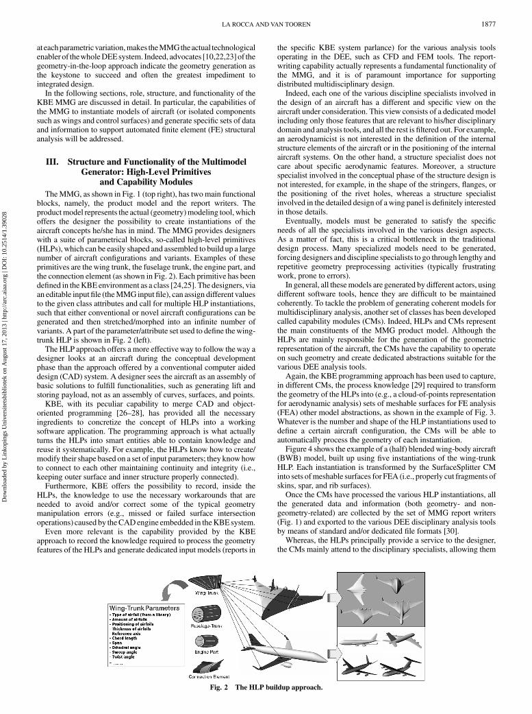
Again, the KBE programming approach has been used to capture,in different CMs, the process knowledge [29] required to transformthe geometry of the HLPs into (e.g., a cloud-of-points representationfor aerodynamic analysis) sets of meshable surfaces for FE analysis(FEA) other model abstractions, as shown in the example of Fig. 3.Whatever is the number and shape of the HLP instantiations used todefine a certain aircraft configuration, the CMs will be able toautomatically process the geometry of each instantiation.
Figure 4 shows the example of a (half) blended wing-body aircraft(BWB) model, built up using five instantiations of the wing-trunkHLP. Each instantiation is transformed by the SurfaceSplitter CMinto sets ofmeshable surfaces for FEA (i.e., properly cut fragments ofskins, spar, and rib surfaces).
Once the CMs have processed the various HLP instantiations, allthe generated data and information (both geometry- and non-geometry-related) are collected by the set of MMG report writers(Fig. 1) and exported to the various DEE disciplinary analysis toolsby means of standard and/or dedicated file formats [30].
Whereas, the HLPs principally provide a service to the designer,the CMs mainly attend to the disciplinary specialists, allowing them
Fig. 2 The HLP buildup approach.
LA ROCCA AND VAN TOOREN 1877
Dow
nloa
ded
by L
inko
ping
s U
nive
rsite
tsbi
blio
tek
on A
ugus
t 17,
201
3 | h
ttp://
arc.
aiaa
.org
| D
OI:
10.
2514
/1.3
9028
to use their own analysis tools without the overhead of many lengthyand tedious preprocessing operations.
To offer the reader a deeper insight into the working mechanismsof HLPs and CMs, the next two sections specifically address themodeling process of a generic wing structure and the definitionof the SurfaceSplitter CM. The link between the MMG andthe PATRAN/NASTRAN FEA environment will be illustrated,showing how the KBE approach can enable the automation of theentire process: from the configuration of the aircraft structure to thelaunch of the structural solver.
IV. Parametric Definition of a Generic WingStructure Configuration
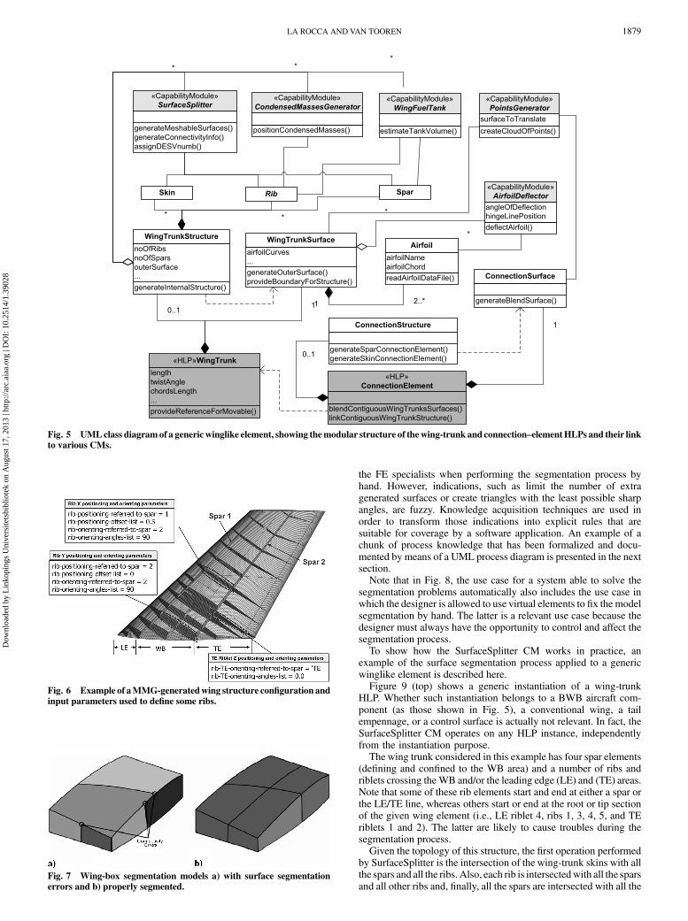
The unified modeling language (UML) class diagram in Fig. 5defines the MMG responsible for modeling and preprocessing anywinglike system (e.g., a wing, a canard, a tail empennage, etc.). Itshows the relations between the wing trunk, the connection element,and various CM classes. Four CMs are those previously illustrated inFig. 3, namely, SurfaceSplitter, CondensedMassesGenerator, Wing-FuelTank, and PointsGenerator.
The wing-trunk and connection-element HLPs consist of twomain components: one for the generation of the outer surface, and theother for the internal structure. Although a separated module, theinner structure of theHLP is defined associatively to the outer surface(i.e., when the external shape of the winglike system is modified, forexample, by a change in airfoil selection, the shape of the variousstructural elements automatically adapts). Although not shown here,the same principle has been applied in the definition of the fuselagetrunk and the relative structure.
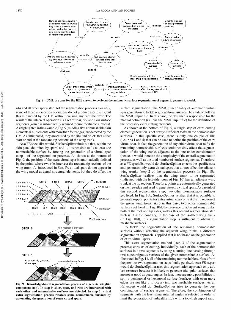
Using the MMG structural design capabilities developed so far,designers can define any number of ribs, spars, stringers, frames, andfloor elements and affect position and orientation of each oneindividually. Number, position, and orientation of each element areassigned using lists of parameters published in the MMG input filetogether with the parameters defining the aircraft outer surfaces.Figure 6 shows an example of a generic wing element generated bythe MMG and the parameter definition of two ribs and one trailingedge (TE) riblet. In fact, the MMG allows different approaches forpositioning and orienting the various structural elements, using asreference other structural elements, or reference vectors like theflightdirection. In the example of Fig. 6, rib x is positioned on a plane thatintersects spar 1 at 50% of the spar length and is oriented at 90 degwith respect to the direction of spar 2. Rib y is positioned on a planethat passes through the root of spar 2 (0% of the spar 2 length) and isoriented at 90 deg with respect to the same spar 2. Ribs and LE/TEriblets can be generated and oriented independently from oneanother. Partial ribs and runout spars (see the center spar in theexample of Fig. 6) can be defined as well.
In addition, the user can define so-called virtual ribs and spars,which are support entities that can be used as a reference for other realelements. An important point is that, although a virtual spar or ribdoes not appear in the model, it actually affects the model for whatconcerns the segmentation of the surfaces (as discussed in the nextsection). Spars and ribs can also be defined as partially virtualelements. In the example of Fig. 6, the center spar starting at the rootsection and running out at the fourth rib actually becomes virtual afterthe fourth rib. Though the center spar of the example is not physicallypresent in the area between the fourth rib and the wingtip section, itstill causes the same skin and rib segmentation as a real full extendingspar. Additionally, it can be used for positioning and orienting ribs asany normal spar.
V. Knowledge-Based Surface Segmentation to SupportFinite Element Analysis Automation
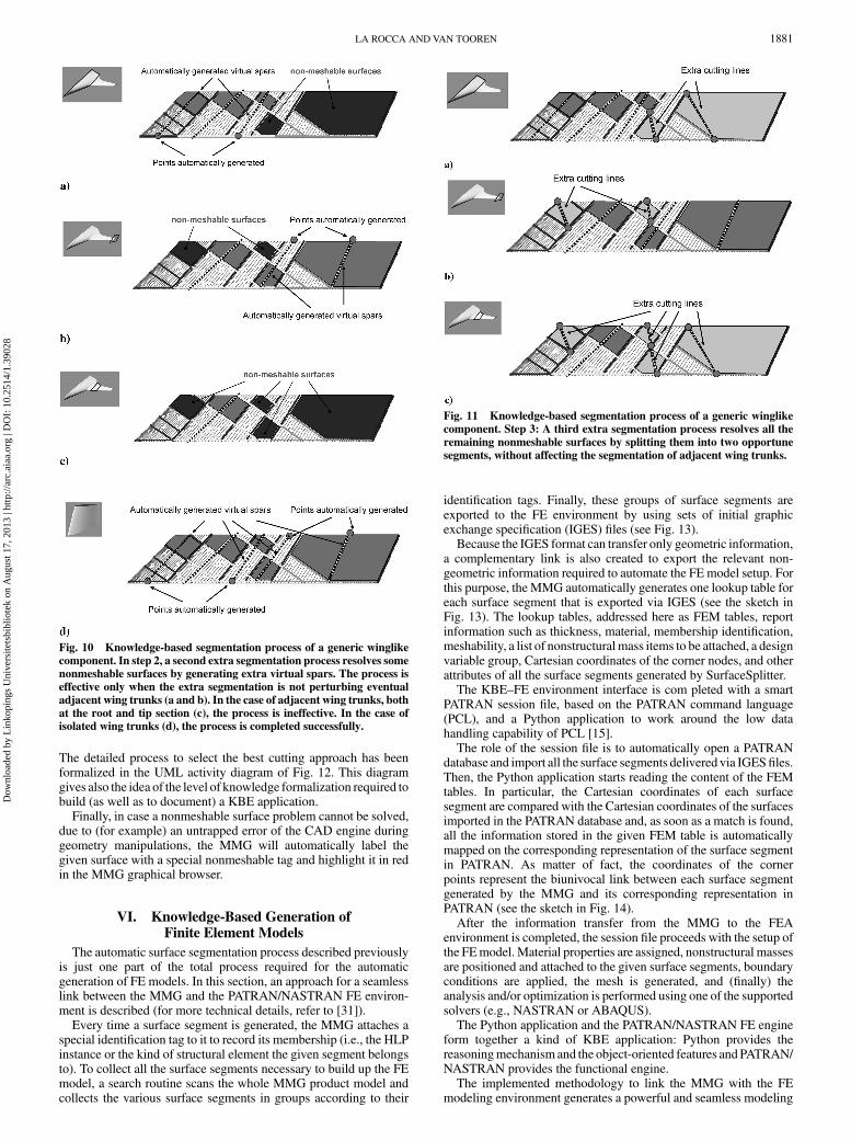
To set up a FE model from the untrimmed geometry producedby the design department, the FE specialist will have to perform a lotof manual work to prepare the model geometry for meshing. Thesurfaces of all the model components (e.g., the skins, the spars, theribs, and the riblets in the case of a wing model) have to be cut alongtheir intersections in order to produce sets of meshable surfaces (i.e.,surface segments which have no more than four edges, each edgematching with only one edge of the adjacent surface segments).Figure 7 shows two segmentations of a wing-box (WB): one isproperly performed, and the other shows connectivity errors [31].This so-called surface segmentation process is well known to be timeexpensive and often not trivial. Additionally, every time a changeoccurs in the model topology, the segmentation process has to beperformed again. Unfortunately, only when all model surfaces areproperly segmented will the automatic meshing functionalitiesprovided by most of the FE preprocessors work.
Therefore, the segmentation process features all the characteristicsof a good candidate for translation into a KBE application: length,repetition, and plenty of rule-based geometry manipulations. TheFE specialist applies a set of mental rules and best practiceswhen manually performing the segmentation process. By means ofknowledge acquisition techniques [32,33], a large part of these rulesand best practices has been elicited through interviews with FEexperts and then captured inside the SurfaceSplitter CM. Aspreviously illustrated in Fig. 5, given a generic aircraft model builtwith any number of HLPs instantiations, the SurfaceSplitter is able toprocess, one by one, all of the various HLP instantiations and finallydeliver a set of surfaces that are suitable to be meshed (whatever thetopology of the generic aircraft).
Figure 8 shows the use case elaborated during the development ofthe SurfaceSplitter module (note that it does not show the technicalimplementation of the segmentation process [34]) and includes anumber of constraints/indications provided by FE specialists. Thoseindications (see the text in curly brackets in Fig. 8) form extremelyvaluable information because they reflect the mental scheme used by
Fig. 3 CMs process a wing-trunk HLP instantiation into a set of model
abstractions to support different analyses. From top left, counter
clockwise, the following CMs are shown in action: PointsGenerator,PanelsGenerator, CondensedMassesGenerator, WingFuelTank, and
SurfaceSplitter.
Fig. 4 The SurfaceSplitter CM processes all the wing-trunk HLP
instantiations used to model a BWB into sets of meshable surfaces to
support FEA.
1878 LA ROCCA AND VAN TOOREN
Dow
nloa
ded
by L
inko
ping
s U
nive
rsite
tsbi
blio
tek
on A
ugus
t 17,
201
3 | h
ttp://
arc.
aiaa
.org
| D
OI:
10.
2514
/1.3
9028
the FE specialists when performing the segmentation process byhand. However, indications, such as limit the number of extragenerated surfaces or create triangles with the least possible sharpangles, are fuzzy. Knowledge acquisition techniques are used inorder to transform those indications into explicit rules that aresuitable for coverage by a software application. An example of achunk of process knowledge that has been formalized and docu-mented by means of a UML process diagram is presented in the nextsection.
Note that in Fig. 8, the use case for a system able to solve thesegmentation problems automatically also includes the use case inwhich the designer is allowed to use virtual elements to fix the modelsegmentation by hand. The latter is a relevant use case because thedesigner must always have the opportunity to control and affect thesegmentation process.
To show how the SurfaceSplitter CM works in practice, anexample of the surface segmentation process applied to a genericwinglike element is described here.
Figure 9 (top) shows a generic instantiation of a wing-trunkHLP. Whether such instantiation belongs to a BWB aircraft com-ponent (as those shown in Fig. 5), a conventional wing, a tailempennage, or a control surface is actually not relevant. In fact, theSurfaceSplitter CM operates on any HLP instance, independentlyfrom the instantiation purpose.
The wing trunk considered in this example has four spar elements(defining and confined to the WB area) and a number of ribs andriblets crossing theWB and/or the leading edge (LE) and (TE) areas.Note that some of these rib elements start and end at either a spar orthe LE/TE line, whereas others start or end at the root or tip sectionof the given wing element (i.e., LE riblet 4, ribs 1, 3, 4, 5, and TEriblets 1 and 2). The latter are likely to cause troubles during thesegmentation process.
Given the topology of this structure, the first operation performedby SurfaceSplitter is the intersection of the wing-trunk skins with allthe spars and all the ribs. Also, each rib is intersectedwith all the sparsand all other ribs and, finally, all the spars are intersected with all the
Fig. 5 UMLclass diagramof a genericwinglike element, showing themodular structure of thewing-trunk and connection–elementHLPs and their link
to various CMs.
Fig. 6 Example of aMMG-generatedwing structure configuration and
input parameters used to define some ribs.
Fig. 7 Wing-box segmentation models a) with surface segmentation
errors and b) properly segmented.
LA ROCCA AND VAN TOOREN 1879
Dow
nloa
ded
by L
inko
ping
s U
nive
rsite
tsbi
blio
tek
on A
ugus
t 17,
201
3 | h
ttp://
arc.
aiaa
.org
| D
OI:
10.
2514
/1.3
9028
ribs and all other spars (step 0 of the segmentation process). Possibly,some of these intersection operations do not produce any results, butthis is handled by the CM without causing any runtime error. Theresult of the intersect operations is a set of spar, rib, and skin surfacesegments (which is subsequently scanned for nonmeshable surfaces).Ashighlighted in the example, Fig. 9 (middle),fivenonmeshable skinelements (i.e., elementswithmore than four edges) aredetectedby theCM. As anticipated, they are caused by the ribs and riblets that eitherstart or end at the root and tip sections of the wing trunk.
As a FE specialist would, SurfaceSplitter finds out that, within theskin panel delimited by spar 0 and 1, it is possible to fix at least onenonmeshable surface by forcing the generation of a virtual spar(step 1 of the segmentation process). As shown at the bottom ofFig. 9, the position of the extra virtual spar is automatically definedby the points where two ribs intersect the root and tip sections of thewing trunk. As introduced in Sec. IV, virtual spars do not appear inthe wing model as actual structural elements, but they do affect the
surface segmentation. The MMG functionality of automatic virtualspar generation to tackle segmentation issues can be switched off viathe MMG input file. In this case, the designer is responsible for themanual definition (i.e., via the MMG input file) for the definition ofthe necessary extra cutting elements.
As shown at the bottom of Fig. 9, a single step of extra cuttingelement generation is not always sufficient to fix all the nonmeshablesurfaces. In this specific case, there is only one couple of ribs(i.e., ribs 1 and 4) that can be used to define the position of the extravirtual spar. In fact, the generation of any other virtual spar to fix theremaining nonmeshable surfaces could possibly affect the segmen-tation of the wing trunks adjacent to the one under consideration(hence, it would increase the complexity of the overall segmentationprocess, as well as the total number of surface segments). Therefore,as a FE specialist would do, SurfaceSplitter checks the specific caseand generates only extra virtual spars that do not affect the adjacentwing trunks (step 2 of the segmentation process). In Fig. 10a,SurfaceSplitter realizes that the wing trunk to be segmented(indicated with the left-side icons of Fig. 10) has an adjacent wingtrunk at the tip section. Therefore, points are automatically generatedon the free edge and used to generate extra virtual spars. As a result ofthis second segmentation step, two other nonmeshable surfacesget fixed. In Fig. 10b, SurfaceSplitter verifies that it is possible togenerate support points for extra virtual spars only at the tip section ofthe given wing trunk. Also in this case, two other nonmeshablesurfaces get fixed. In Fig. 10d, the presence of adjacent wing trunks,both at the root and tip sides, makes this second segmentation stepuseless. On the contrary, in the case of the isolated wing trunk(in Fig. 10d), this segmentation step is sufficient to obtain allmeshable surfaces.
To tackle the segmentation of the remaining nonmeshablesurfaces without affecting the adjacent wing trunks, a differentsegmentation approach is applied that is not based on the generationof extra virtual spars.
This extra segmentation method (step 3 of the segmentationprocess) consists of cutting, individually, each of the nonmeshablesurfaces into two segments by using a cutting line passing throughtwo noncontiguous vertices of the given nonmeshable surface. Asillustrated in Fig. 11, all of the remaining nonmeshable surfaces fromthe previous two segmentation steps finally get fixed. As a FE expertwould do, SurfaceSplitter uses this segmentation approach only as alast resource because it is likely to generate triangular surfaces thatare not as good as quadrangles. In fact, there are more possibilities tosplit a pentagonal or hexagonal surface (surfaces with even moreedges are not likely to occur) into two meshable surfaces. As anFE expert would do, SurfaceSplitter tries to generate the bestcombination of surface segments. Therefore, the combination ofsegments with the least sharp internal angles is selected in order tolimit the generation of unhealthy FEs with a too-high aspect ratio.
Fig. 8 UML use case for the KBE system to perform the automatic surface segmentation of a generic geometric model.
Fig. 9 Knowledge-based segmentation process of a generic winglike
component (top). In step 0, skins, spar, and ribs are intersected witheach other and nonmeshable surfaces are detected. In step 1, a first
extra segmentation process resolves some nonmeshable surfaces by
automating the generation of some virtual spars.
1880 LA ROCCA AND VAN TOOREN
Dow
nloa
ded
by L
inko
ping
s U
nive
rsite
tsbi
blio
tek
on A
ugus
t 17,
201
3 | h
ttp://
arc.
aiaa
.org
| D
OI:
10.
2514
/1.3
9028
The detailed process to select the best cutting approach has beenformalized in the UML activity diagram of Fig. 12. This diagramgives also the idea of the level of knowledge formalization required tobuild (as well as to document) a KBE application.
Finally, in case a nonmeshable surface problem cannot be solved,due to (for example) an untrapped error of the CAD engine duringgeometry manipulations, the MMG will automatically label thegiven surface with a special nonmeshable tag and highlight it in redin the MMG graphical browser.
VI. Knowledge-Based Generation ofFinite Element Models
The automatic surface segmentation process described previouslyis just one part of the total process required for the automaticgeneration of FE models. In this section, an approach for a seamlesslink between the MMG and the PATRAN/NASTRAN FE environ-ment is described (for more technical details, refer to [31]).
Every time a surface segment is generated, the MMG attaches aspecial identification tag to it to record its membership (i.e., the HLPinstance or the kind of structural element the given segment belongsto). To collect all the surface segments necessary to build up the FEmodel, a search routine scans the whole MMG product model andcollects the various surface segments in groups according to their
identification tags. Finally, these groups of surface segments areexported to the FE environment by using sets of initial graphicexchange specification (IGES) files (see Fig. 13).
Because the IGES format can transfer only geometric information,a complementary link is also created to export the relevant non-geometric information required to automate the FE model setup. Forthis purpose, the MMG automatically generates one lookup table foreach surface segment that is exported via IGES (see the sketch inFig. 13). The lookup tables, addressed here as FEM tables, reportinformation such as thickness, material, membership identification,meshability, a list of nonstructural mass items to be attached, a designvariable group, Cartesian coordinates of the corner nodes, and otherattributes of all the surface segments generated by SurfaceSplitter.
The KBE–FE environment interface is com pleted with a smartPATRAN session file, based on the PATRAN command language(PCL), and a Python application to work around the low datahandling capability of PCL [15].
The role of the session file is to automatically open a PATRANdatabase and import all the surface segments delivered via IGESfiles.Then, the Python application starts reading the content of the FEMtables. In particular, the Cartesian coordinates of each surfacesegment are compared with the Cartesian coordinates of the surfacesimported in the PATRAN database and, as soon as a match is found,all the information stored in the given FEM table is automaticallymapped on the corresponding representation of the surface segmentin PATRAN. As matter of fact, the coordinates of the cornerpoints represent the biunivocal link between each surface segmentgenerated by the MMG and its corresponding representation inPATRAN (see the sketch in Fig. 14).
After the information transfer from the MMG to the FEAenvironment is completed, the session file proceeds with the setup ofthe FEmodel.Material properties are assigned, nonstructural massesare positioned and attached to the given surface segments, boundaryconditions are applied, the mesh is generated, and (finally) theanalysis and/or optimization is performed using one of the supportedsolvers (e.g., NASTRAN or ABAQUS).
The Python application and the PATRAN/NASTRAN FE engineform together a kind of KBE application: Python provides thereasoningmechanism and the object-oriented features andPATRAN/NASTRAN provides the functional engine.
The implemented methodology to link the MMG with the FEmodeling environment generates a powerful and seamless modeling
Fig. 10 Knowledge-based segmentation process of a generic winglike
component. In step 2, a second extra segmentation process resolves somenonmeshable surfaces by generating extra virtual spars. The process is
effective only when the extra segmentation is not perturbing eventual
adjacent wing trunks (a and b). In the case of adjacent wing trunks, both
at the root and tip section (c), the process is ineffective. In the case ofisolated wing trunks (d), the process is completed successfully.
Fig. 11 Knowledge-based segmentation process of a generic winglike
component. Step 3: A third extra segmentation process resolves all the
remaining nonmeshable surfaces by splitting them into two opportune
segments, without affecting the segmentation of adjacent wing trunks.
LA ROCCA AND VAN TOOREN 1881
Dow
nloa
ded
by L
inko
ping
s U
nive
rsite
tsbi
blio
tek
on A
ugus
t 17,
201
3 | h
ttp://
arc.
aiaa
.org
| D
OI:
10.
2514
/1.3
9028
Fig. 12 Activity diagram detailing the extra cutting process to deal with surfaces segments that have more than four edges.
Fig. 13 Seamless link between the MMG and the FEA environment.IGES files are used to transfer the geometry of the segmented surfaces;
lookup tables (FEM tables) are used to transfer the information related
to each surface segment and required to set up the FE model.
Fig. 14 The mapping process of the FEM table content is based on thematch of the Cartesian coordinates of the corner points of the surfaces
stored in the PATRAN database, with the Cartesian coordinates
reported in the FEM tables.
1882 LA ROCCA AND VAN TOOREN
Dow
nloa
ded
by L
inko
ping
s U
nive
rsite
tsbi
blio
tek
on A
ugus
t 17,
201
3 | h
ttp://
arc.
aiaa
.org
| D
OI:
10.
2514
/1.3
9028
and analysis system, which allows the designer to evaluate manydifferent design configurations, without worrying about a new FEmodel each time avariation is enforced in the shape or topology of theaircraft configuration.
VII. Results
A. MOB Blended Wing-Body Design Case
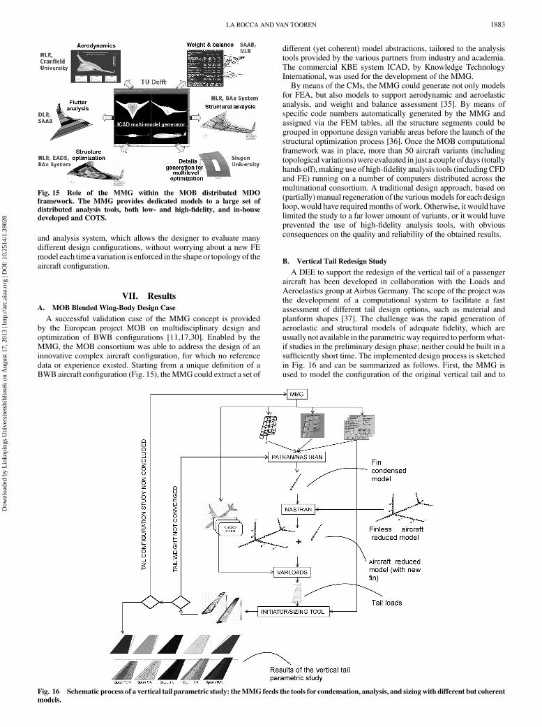
A successful validation case of the MMG concept is providedby the European project MOB on multidisciplinary design andoptimization of BWB configurations [11,17,30]. Enabled by theMMG, the MOB consortium was able to address the design of aninnovative complex aircraft configuration, for which no referencedata or experience existed. Starting from a unique definition of aBWB aircraft configuration (Fig. 15), theMMGcould extract a set of
different (yet coherent) model abstractions, tailored to the analysistools provided by the various partners from industry and academia.The commercial KBE system ICAD, by Knowledge TechnologyInternational, was used for the development of the MMG.
By means of the CMs, the MMG could generate not only modelsfor FEA, but also models to support aerodynamic and aeroelasticanalysis, and weight and balance assessment [35]. By means ofspecific code numbers automatically generated by the MMG andassigned via the FEM tables, all the structure segments could begrouped in opportune design variable areas before the launch of thestructural optimization process [36]. Once the MOB computationalframework was in place, more than 50 aircraft variants (includingtopological variations)were evaluated in just a couple of days (totallyhands off), making use of high-fidelity analysis tools (including CFDand FE) running on a number of computers distributed across themultinational consortium. A traditional design approach, based on(partially) manual regeneration of the variousmodels for each designloop, would have requiredmonths of work. Otherwise, it would havelimited the study to a far lower amount of variants, or it would haveprevented the use of high-fidelity analysis tools, with obviousconsequences on the quality and reliability of the obtained results.
B. Vertical Tail Redesign Study
A DEE to support the redesign of the vertical tail of a passengeraircraft has been developed in collaboration with the Loads andAeroelastics group at Airbus Germany. The scope of the project wasthe development of a computational system to facilitate a fastassessment of different tail design options, such as material andplanform shapes [37]. The challenge was the rapid generation ofaeroelastic and structural models of adequate fidelity, which areusually not available in the parametric way required to performwhat-if studies in the preliminary design phase; neither could be built in asufficiently short time. The implemented design process is sketchedin Fig. 16 and can be summarized as follows. First, the MMG isused to model the configuration of the original vertical tail and to
Fig. 15 Role of the MMG within the MOB distributed MDOframework. The MMG provides dedicated models to a large set of
distributed analysis tools, both low- and high-fidelity, and in-house
developed and COTS.
Fig. 16 Schematic process of a vertical tail parametric study: theMMG feeds the tools for condensation, analysis, and sizing with different but coherent
models.
LA ROCCA AND VAN TOOREN 1883
Dow
nloa
ded
by L
inko
ping
s U
nive
rsite
tsbi
blio
tek
on A
ugus
t 17,
201
3 | h
ttp://
arc.
aiaa
.org
| D
OI:
10.
2514
/1.3
9028
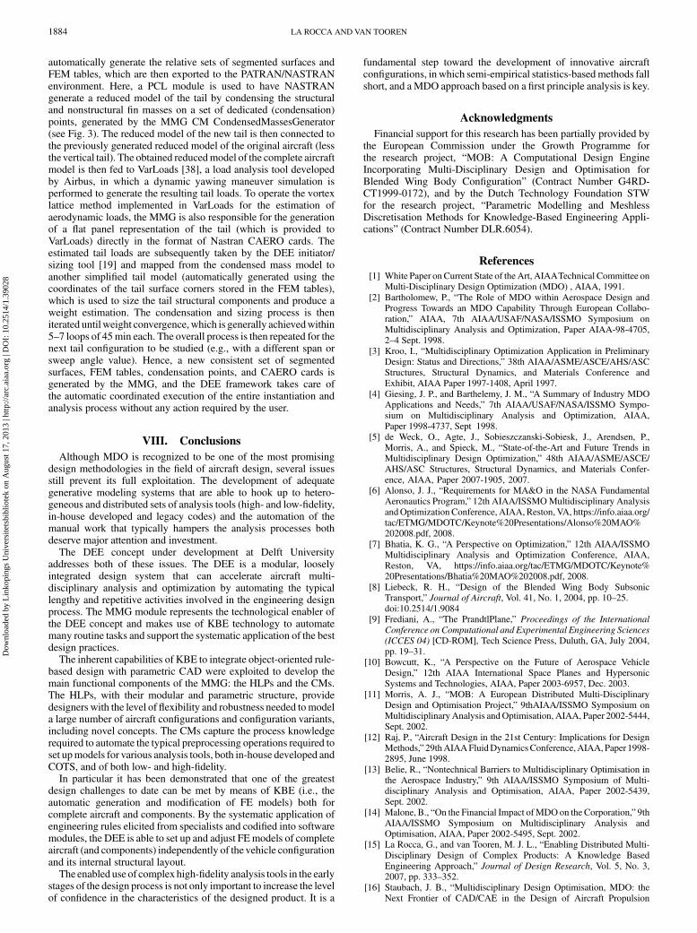
automatically generate the relative sets of segmented surfaces andFEM tables, which are then exported to the PATRAN/NASTRANenvironment. Here, a PCL module is used to have NASTRANgenerate a reduced model of the tail by condensing the structuraland nonstructural fin masses on a set of dedicated (condensation)points, generated by the MMG CM CondensedMassesGenerator(see Fig. 3). The reduced model of the new tail is then connected tothe previously generated reduced model of the original aircraft (lessthe vertical tail). The obtained reducedmodel of the complete aircraftmodel is then fed to VarLoads [38], a load analysis tool developedby Airbus, in which a dynamic yawing maneuver simulation isperformed to generate the resulting tail loads. To operate the vortexlattice method implemented in VarLoads for the estimation ofaerodynamic loads, the MMG is also responsible for the generationof a flat panel representation of the tail (which is provided toVarLoads) directly in the format of Nastran CAERO cards. Theestimated tail loads are subsequently taken by the DEE initiator/sizing tool [19] and mapped from the condensed mass model toanother simplified tail model (automatically generated using thecoordinates of the tail surface corners stored in the FEM tables),which is used to size the tail structural components and produce aweight estimation. The condensation and sizing process is theniterated untilweight convergence,which is generally achievedwithin5–7 loops of 45min each. The overall process is then repeated for thenext tail configuration to be studied (e.g., with a different span orsweep angle value). Hence, a new consistent set of segmentedsurfaces, FEM tables, condensation points, and CAERO cards isgenerated by the MMG, and the DEE framework takes care ofthe automatic coordinated execution of the entire instantiation andanalysis process without any action required by the user.
VIII. Conclusions
Although MDO is recognized to be one of the most promisingdesign methodologies in the field of aircraft design, several issuesstill prevent its full exploitation. The development of adequategenerative modeling systems that are able to hook up to hetero-geneous and distributed sets of analysis tools (high- and low-fidelity,in-house developed and legacy codes) and the automation of themanual work that typically hampers the analysis processes bothdeserve major attention and investment.
The DEE concept under development at Delft Universityaddresses both of these issues. The DEE is a modular, looselyintegrated design system that can accelerate aircraft multi-disciplinary analysis and optimization by automating the typicallengthy and repetitive activities involved in the engineering designprocess. The MMG module represents the technological enabler ofthe DEE concept and makes use of KBE technology to automatemany routine tasks and support the systematic application of the bestdesign practices.
The inherent capabilities of KBE to integrate object-oriented rule-based design with parametric CAD were exploited to develop themain functional components of the MMG: the HLPs and the CMs.The HLPs, with their modular and parametric structure, providedesigners with the level of flexibility and robustness needed tomodela large number of aircraft configurations and configuration variants,including novel concepts. The CMs capture the process knowledgerequired to automate the typical preprocessing operations required toset upmodels for various analysis tools, both in-house developed andCOTS, and of both low- and high-fidelity.
In particular it has been demonstrated that one of the greatestdesign challenges to date can be met by means of KBE (i.e., theautomatic generation and modification of FE models) both forcomplete aircraft and components. By the systematic application ofengineering rules elicited from specialists and codified into softwaremodules, the DEE is able to set up and adjust FEmodels of completeaircraft (and components) independently of the vehicle configurationand its internal structural layout.
The enabled use of complex high-fidelity analysis tools in the earlystages of the design process is not only important to increase the levelof confidence in the characteristics of the designed product. It is a
fundamental step toward the development of innovative aircraftconfigurations, in which semi-empirical statistics-basedmethods fallshort, and aMDO approach based on a first principle analysis is key.
Acknowledgments
Financial support for this research has been partially provided bythe European Commission under the Growth Programme forthe research project, “MOB: A Computational Design EngineIncorporating Multi-Disciplinary Design and Optimisation forBlended Wing Body Configuration” (Contract Number G4RD-CT1999-0172), and by the Dutch Technology Foundation STWfor the research project, “Parametric Modelling and MeshlessDiscretisation Methods for Knowledge-Based Engineering Appli-cations” (Contract Number DLR.6054).
References
[1] White Paper onCurrent State of the Art, AIAATechnical Committee onMulti-Disciplinary Design Optimization (MDO) , AIAA, 1991.
[2] Bartholomew, P., “The Role of MDO within Aerospace Design andProgress Towards an MDO Capability Through European Collabo-ration,” AIAA, 7th AIAA/USAF/NASA/ISSMO Symposium onMultidisciplinary Analysis and Optimization, Paper AIAA-98-4705,2–4 Sept. 1998.
[3] Kroo, I., “Multidisciplinary Optimization Application in PreliminaryDesign: Status and Directions,” 38th AIAA/ASME/ASCE/AHS/ASCStructures, Structural Dynamics, and Materials Conference andExhibit, AIAA Paper 1997-1408, April 1997.
[4] Giesing, J. P., and Barthelemy, J. M., “A Summary of Industry MDOApplications and Needs,” 7th AIAA/USAF/NASA/ISSMO Sympo-sium on Multidisciplinary Analysis and Optimization, AIAA,Paper 1998-4737, Sept 1998.
[5] de Weck, O., Agte, J., Sobieszczanski-Sobiesk, J., Arendsen, P.,Morris, A., and Spieck, M., “State-of-the-Art and Future Trends inMultidisciplinary Design Optimization,” 48th AIAA/ASME/ASCE/AHS/ASC Structures, Structural Dynamics, and Materials Confer-ence, AIAA, Paper 2007-1905, 2007.
[6] Alonso, J. J., “Requirements for MA&O in the NASA FundamentalAeronautics Program,” 12th AIAA/ISSMOMultidisciplinary AnalysisandOptimization Conference, AIAA,Reston, VA, https://info.aiaa.org/tac/ETMG/MDOTC/Keynote%20Presentations/Alonso%20MAO%202008.pdf, 2008.
[7] Bhatia, K. G., “A Perspective on Optimization,” 12th AIAA/ISSMOMultidisciplinary Analysis and Optimization Conference, AIAA,Reston, VA, https://info.aiaa.org/tac/ETMG/MDOTC/Keynote%20Presentations/Bhatia%20MAO%202008.pdf, 2008.
[8] Liebeck, R. H., “Design of the Blended Wing Body SubsonicTransport,” Journal of Aircraft, Vol. 41, No. 1, 2004, pp. 10–25.doi:10.2514/1.9084
[9] Frediani, A., “The PrandtlPlane,” Proceedings of the International
Conference on Computational and Experimental Engineering Sciences
(ICCES 04) [CD-ROM], Tech Science Press, Duluth, GA, July 2004,pp. 19–31.
[10] Bowcutt, K., “A Perspective on the Future of Aerospace VehicleDesign,” 12th AIAA International Space Planes and HypersonicSystems and Technologies, AIAA, Paper 2003-6957, Dec. 2003.
[11] Morris, A. J., “MOB: A European Distributed Multi-DisciplinaryDesign and Optimisation Project,” 9thAIAA/ISSMO Symposium onMultidisciplinary Analysis andOptimisation, AIAA, Paper 2002-5444,Sept. 2002.
[12] Raj, P., “Aircraft Design in the 21st Century: Implications for DesignMethods,”29thAIAAFluidDynamicsConference,AIAA, Paper 1998-2895, June 1998.
[13] Belie, R., “Nontechnical Barriers to Multidisciplinary Optimisation inthe Aerospace Industry,” 9th AIAA/ISSMO Symposium of Multi-disciplinary Analysis and Optimisation, AIAA, Paper 2002-5439,Sept. 2002.
[14] Malone, B., “On the Financial Impact ofMDO on the Corporation,” 9thAIAA/ISSMO Symposium on Multidisciplinary Analysis andOptimisation, AIAA, Paper 2002-5495, Sept. 2002.
[15] La Rocca, G., and van Tooren, M. J. L., “Enabling Distributed Multi-Disciplinary Design of Complex Products: A Knowledge BasedEngineering Approach,” Journal of Design Research, Vol. 5, No. 3,2007, pp. 333–352.
[16] Staubach, J. B., “Multidisciplinary Design Optimisation, MDO: theNext Frontier of CAD/CAE in the Design of Aircraft Propulsion
1884 LA ROCCA AND VAN TOOREN
Dow
nloa
ded
by L
inko
ping
s U
nive
rsite
tsbi
blio
tek
on A
ugus
t 17,
201
3 | h
ttp://
arc.
aiaa
.org
| D
OI:
10.
2514
/1.3
9028
Systems,” AIAA/ICAS International Air and Space Symposium andExposition, AIAA Paper 2003-2803, 14–17 July 2003.
[17] La Rocca, G., and van Tooren, M. J. L., “A Modular ReconfigurableSoftware Modelling Tool to Support Distributed MultidisciplinaryDesign and Optimisation of Complex Products,” 16th CIRP
International Design Seminar [CD-ROM], College International pourla Recherche en Productique, Kananaskis, AB, Canada, 2006.
[18] van Tooren, M. J. L., Nawijn, M., Berends, J. P. T. J., and Schut, E. J.,“Aircraft Design Support Using Knowledge Engineering andOptimisation Techniques,” 46th AIAA/ASME/ASCE/AHS/ASCStructures, Structural Dynamics, and Materials Conference, AIAAPaper 2005-2205, April 2005.
[19] Schut, E. J., and van Tooren, M. J. L., “Design ‘Feasilization’ UsingKnowledge-Based Engineering and Optimization Techniques,”Journal of Aircraft, Vol. 44, No. 6, 2007, pp. 1776–1786.doi:10.2514/1.24688
[20] Berends, J. P. T. J., and van Tooren, M. J. L., “An Agent System Co-operating as a Design Build Team in a Multidisciplinary DesignEnvironment,” 44th AIAA Aerospace Science Meeting and Exhibit,AIAA Paper 2006-1482, Jan. 2006.
[21] Samareh, J. A., “Aerodynamic Shape Optimization Based on Free-Form Deformation,” 10th AIAA/ISSMO Multidisciplinary Analysisand Optimization Conference, AIAA Paper 2004-4630, Aug. 2004.
[22] Vandenbrande, J. H., Grandine, T.A., andHogan, T., “The Search of thePerfect Body: Shape Control for Multidisciplinary Design Optimiza-tion,” 44th AIAA Aerospace Science Meeting and Exhibit, AIAAPaper 2006-928, Jan. 2006.
[23] Carty, A., and Davies, C., “Fusion of Aircraft Synthesis and ComputerAided Design,” 10th AIAA/ISSMO Multidisciplinary Analysis andOptimization Conference, AIAA Paper 2004-4433, Aug. 2004.
[24] Rumbaugh, J., Blaha, M., Premerlani, W., Eddy, F., and Lorensen, W.,Object-Oriented Modeling and Design, Prentice–Hall, EnglewoodCliff, NJ, 1991.
[25] Sully, P.,Modelling the World with Objects, Prentice–Hall, EnglewoodCliff, NJ, 1993.
[26] Cooper, D. J., and La Rocca, G., “Knowledge-Based Techniques forDeveloping Engineering Applications in the 21st Century,” 7th AIAAAviation Technology, Integration and Operations Conference, AIAAPaper 2007-7711, Sept. 2007.
[27] Cooper, S., Fan, I., and Li, G., “Achieving Competitive Advantage
Through Knowledge Based Engineering: A Best Practice Guide,” TheDepartment of Trade and Industry, Cranfield, UK, 2001.
[28] Milton, N., Knowledge Technologies, Polimetrica, Monza, Italy, 2008.[29] Rhem, A. J.,UML for Developing Knowledge Management Systems,
Auerbach, Boca Raton, FL, 2006.[30] Morris, A. J., Arendsen, P., La Rocca, G., Laban, M., Voss, R., and
Hönlinger, H., “MOB:AEuropean Project onMultidisciplinary DesignOptimisation,”Proceedings of the 24th ICAS [CD-ROM], InternationalCouncil of the Aeronautical Sciences, Stockholm, Sept. 2004.
[31] Nawijn, M., and van Tooren, M. J. L., “Automated Finite ElementAnalysis in aKnowledgeBasedEngineeringEnvironment,” 44thAIAAAerospace Science Meeting and Exhibit, AIAA Paper 2006-947,Jan. 2006.
[32] Shreiber, G., Akkremans, H., Anjewierden, A., de Hoog, R., Shadbolt,N., Van de Velde, W., and Wielinga, B., Knowledge Engineering
and Management: The CommonKADS Methodology, MIT Press,Cambridge, MA, 2000.
[33] Milton, N., Knowledge Acquisition in Practice: A Step-by-Step Guide,Springer–Verlag, London, 2007.
[34] Booch, G., Rumbaugh, J., and Jacobson, I., Unified Modeling
Language User Guide, Addison Wesley Longman, Reading, MA,2005.
[35] LaRocca,G., Krakers, L., and vanTooren,M. J. L., “Development of anICAD Generative Model for Blended Wing Body Aircraft Design,”9th AIAA/ISSMO Symposium on Multidisciplinary Analysis andOptimisation, AIAA Paper 2002-5447, Sept. 2002.
[36] Laban, M., Arendsen, P., Rouwhorst, W. F. J. A., and Vankan, W. J., “AComputational Design Engine for Multidisciplinary Optimisation withApplication to a Blended Wing Body Configuration,” 9th AIAA/ISSMO Symposium on Multidisciplinary Analysis and Optimisation,AIAA Paper 2002-5446, Sept. 2002.
[37] Cerulli, C., Schut, E. J., Berends, J. P. T. J., and van Tooren, M. J. L.,“Tail Optimization and Redesign in a Multi Agent Task Environment,”47th AIAA/ASME/ASCE/AHS/ASC Structures, Structural Dynamics,and Materials Conference, AIAA Paper 2006-2241, 2006.
[38] Hofstee, J., Kier, T., Cerulli, C., and Looye, G., “A Variable, FullyFlexible Dynamic Response Tool for Special Investigation (Var-Loads),”Proceedings of the CEAS/AIAA/NVvL International Forum on
Aeroelasticity and Structural Dynamics, Nederlandse Verening voorLuchtvaarttechniek, Amsterdam, The Netherlands, 2003.
LA ROCCA AND VAN TOOREN 1885
Dow
nloa
ded
by L
inko
ping
s U
nive
rsite
tsbi
blio
tek
on A
ugus
t 17,
201
3 | h
ttp://
arc.
aiaa
.org
| D
OI:
10.
2514
/1.3
9028